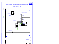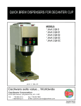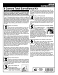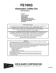
1
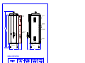
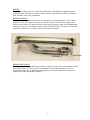
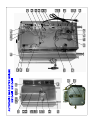
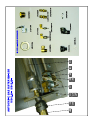
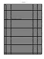
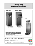
AUTOMATIC GAS WATER BOILER
ME10-GN ME15-GN
18 Gauge Type 304L
Stainless Steel
construction to resist
corrosion.
Solid State water level
control for automatic
refill
CONTENTS
Specifications
Start up Instructions
Trouble Shooting Guide
Parts List
Wiring Diagram
Operation Manual
NQ24A 12-2006
POWER
SWITCH
GAS FLUE
LINE CORD
WITH PLUG
ME10-GN
"B"
CAUTION
"A"
WATER INLET
(1/4 " FLARE)
HOT SURFACES
TEMPERATURE
CONTROL
GAS INLET
(3/8 " NPT)
TEMPERATURE CONTROL
NP87A
OVERFLOW
4.0
SIDE ACCESS DOOR
(SLIDES UP)
THERMOMETER
14.0
3.4
5.0
16.0
GENERAL SPECIFICATIONS
GAS SPECIFICATIONS
MODEL NO.
NATURAL GAS
BTU/ HR @ 3.5" W.C.
ME10-GN ME15-GN
12,000
PROPANE GAS
BTU/ HR @ 10" W.C.
12,000
ELECTRICAL SPECIFICATIONS
NOTE: UNIT IS SUPPLIED WITH A GROUNDED 120V-15A LINE CORD AND PLUG (NEMA 5-15P).
1
FOR YOUR SAFETY
DO NOT STORE OR USE GASOLINE OR OTHER FLAMMABLE VAPORS AND
LIQUIDS IN THE VICINITY OF THIS OR ANY OTHER APPLIANCE.
THIS INSTALLATION MUST CONFORM WITH THE NATIONAL FUEL GAS CODE,
ANSI Z223.1 (LATEST EDITION).
WARNING: IMPROPER INSTALLATION, ADJUSTMENT, ALTERATION, SERVICE
OR MAINTENANCE CAN CAUSE PROPERTY DAMAGE, INJURY OR DEATH. READ
THE INSTALLATION, OPERATING AND MAINTENANCE INSTRUCTIONS
THOROUGHLY BEFORE INSTALLING OR SERVICING THIS EQUIPMENT.
SAFETY PRECAUTIONS
FOR YOUR SAFETY, THE FOLLOWING SAFETY PRECAUTIONS SHOULD
BE FOLLOWED AND ENFORCED.
IF YOU SMELL GAS:
• OPEN WINDOWS
• DON’T TOUCH ELECTRICAL SWITCHES
• EXTINGUISH OPEN FLAMES
• IMMEDIATELY CALL YOUR GAS SUPPLIER
1. Instructions must be posted in a prominent location and all safety precautions taken
in the event the user smells gas. Obtain this information from your local gas supplier.
2. LIGHTING: Follow the instruction on page 2 and label attached to right side of the
water boiler.
3. Do not place anything over the flue opening.
4. Do not place combustibles or non-combustible materials in the proximity of coffee
urn as this could cause fires or obstruct air flow to the main burners.
5. This installation must conform with local codes, or in absence of local codes with the
National Fuel Gas Code ANSI Z223.1, latest edition.
6. Provide adequate air supply and ventilation.
7. Provide adequate clearance for air openings into the combustion chamber.
8. Provide clearance for servicing and proper operation. Minimum clearance from
combustible construction 8” from back and 6” from side.
9. Boiler must be disconnected from gas supply during any pressure testing of
pipelines in excess of ½ psig, and isolated (by turning off gas shut-off valve) during
any testing less than ½ psig.
10. Retain this manual for future reference.
UNPACKING INSTRUCTION: Carefully unpack the water boiler and inspect immediately
for shipping damages. Your automatic water boiler was shipped in a carton designed to
give maximum protection in normal handling. It was thoroughly inspected before
leaving the factory and the carrier accepted and signed for it. File any claims for
shipping damage or irregularities with the carrier.
2
ASSEMBLY: The four legs and vent cap drain are packed separately with the water
boiler. Install legs by tilting the water boiler on its side and screwing the legs into the
leg supports until hand tight. Carefully right the unit and install in its permanent
location, being sure to leave at least 6” on the right side of the water boiler for access
to the control box. Level the unit by adjusting the bottom pad of the legs. Place the
vent cap into the recess in the top of the unit. Mount the faucet assembly onto the
shank in upright position.
INSTALLATION AND OPERATING INSTRUCTION:
PRE-INSTALLATION INSTRUCTIONS: The installation of your water boiler must be made
by a licensed plumber and the installation must conform with State and Local Codes or
in absence of Local Codes, with the National Fuel Gas Code ANSI Z223.1 a latest
version.
AIR SUPPLY AND VENTILATION: Adequate ventilation and air supply must be provided
in order for the water boiler to operate properly and efficiently. The area in front of and
above the unit must be clear to avoid any obstruction of flow of combustion and
ventilation air. DO NOT under any circumstances, connect the water boiler flue directly
to a building exhaust system or place the flue outlet directly into the plenum of the
exhaust hood as it will adversely affect the gas combustion of the water boiler.
CLEARANCES: Your water boiler is design certified to use on combustible floors. The
side and back clearances for combustible constructions are as follows: 6 inches from
side and 8 inches from back. The water boiler must be installed with 4 inch high legs
provided.
GAS CONNECTION: Before connecting the water boiler to the gas line Examine the gas
specification label attached to the right side panel to be certain that the type of gas for
which the unit is equipped is the same as the gas supply. A 3/8 NPT gas connection is
needed to connect the unit to the gas line. An accessible manual shut-off valve must be
installed in the gas supply line in case of an emergency. The gas supply pipe must be
sized to accommodate all the gas fired equipment that may be connected to it. Check
with your local Gas Company as to proper pipe size. Sealant on all pipe joints must be
resistive to propane gas. Before attempting to light the water boiler, check all joints for
gas tightness using a soap and water solution.
WATER CONNECTION: The unit is supplied with ¼” flare fitting. Connect the copper
tubing with the flare fitting to the water connection at the rear of the machine. The
water line must have a shut-off valve (supplied by a plumber) to a cold water supply.
Water pressure should be 20 lbs. minimum for proper operation.
NOTE: Connecting the unit to a warm water supply will speed by heating and recovery
time.
To turn on the water supply valve plug the line cord into a dedicated 120V grounded
receptacle (NEMA 5-15R). The water will start entering the unit and automatically fill it
to capacity.
PRIMING OR INITIAL FILLING: Turn on the water supply. The unit fills at the rate of 1
gallon per minute. When the water level becomes visible in the sight gauge, turn the
thermostat knob to the ON position. The boiler will now automatically fill to capacity
and heat the water.
LIGHTING AND ADJUSTMENT: Water must be visible in the sight glass before lighting to
pilot. Turn the thermostat knob to its lowest position. Turn gas cock dial to PILOT
position. Depress gas cock dial and light pilot with a long lighted match through the
opening located on the bottom of the urn. Hold in depressed position for approximately
30 sec. or until pilot remains lit when dial is released.
3
NOTE: On the first lighting it may be necessary to hold the dial for a longer period to
allow trapped air to escape from the line.
DIAL SETTINGS AND CORRESPONDING WATER TEMPERATURES:
“1”= 50F, “10”=198F
RELIGHTING: Shut off all gas and wait approximately 5 minutes before relighting the
pilot.
SHUTTING DOWN: For temporary shut down, turn the thermostat to lowest or OFF
position, then turn gas cock dial to PILOT position. To shut boiler down completely,
partially depress and turn gas cock dial to OFF position.
MAINTENANCE OR REPAIR: The owner should contact the manufacturer or an approved
local service company for maintenance or repair of the unit.
CLEANING: The outside of the unit should be cleaned on a regular basis using a soap
solution and a soft cloth or sponge. Abrasive cleaners are not recommended. For
cleaning the burner see section on removal and cleaning.
FOR QUALIFIED SERVICE PERSONNEL ONLY
THERMOSTAT CALIBRATION:
To adjust the temperature of the water in the urn, turn the thermostat knob to “10”and
remove the knob without moving the thermostat shaft. Place narrow bladed screwdriver
(1/8”) into the hollow thermostat shaft and engage center adjustment screw. When
thermometer reading approaches 198F slowly turn the adjustment screw clockwise until
the burner goes out. Turning the screw counter-clockwise will increase the
temperature.
REPLACING SOLENOID VALVE:
1. Shut off water supply and disconnect power to the boiler.
2. Drain off approx. 1 gallon of water from the boiler.
3. Disconnect hose nut from solenoid inlet.
4. Disconnect wires from terminals on solenoid coil.
5. Remove solenoid from cabinet (2 screws).
6. Remove silicon hose from solenoid and slip onto new solenoid and assemble back in
reverse order.
SAFETY PILOT:
Remove pilot adjustment cap on the gas valve and turn adjustment screw to provide
properly sized flame (3/4 inch long).Replace the cap.
Pilot Adjustment Screw
4
BURNER:
The burner is factory set for maximum performance. Should further adjustments be
required loosen slotted hex screw on side of venturi and rotate air shutter until flame
with soft blue inner core is obtained.
BURNER REMOVAL:
The burner can be removed with the unit standing in operating position. Turn off the
gas flow to the unit. Allow the burner to cool off. Remove the wing nut holding the
burner to the frame. Pull down the free burner end, enough to clear the threaded stud
and pull the burner horizontally away from the manifold orifice. The burner can now be
cleaned or replaced. To reinstall, reverse the above procedure.
Air Shutter
Hex Screw
BURNER MAITENANCE:
The burner should be cleaned both inside the venturi portion and on the outside using a
soft bristle brush. The burner must be replaced into the same position as prior to
removal. Once a year, a qualified service agency should be contacted to inspect the
appliance for safe and proper operation.
5
PARTS LIST
No.
PART #
DESCRIPTION
ME10-GN
ME15-GN
1
B012A
HEYCO BUSHING STRAIGHT, SMALL
1
1
2
B033A
TERMINAL BLOCK 3 POSITION
1
1
3
C032S
CD257
LINE CORD W/ PLUG 120V 15A
WATER INLET VALVE 120V
1
1
1
1
4
5
CH32A
THERMOSTAT HARNESS ASSEMBLY
1
1
6
CH415
WIRING HARNESS ASSEMBLY
1
1
7
D022Q
FAUCET, SHANK W/ VALVE
1
1
8
D031A
GUAGE SHIELD, 14 1/2"
1
0
9
D066A
GUAGE SHIELD, 18"
0
1
10
E009A
1
F091A
OVERFLOW FITTING W/ NUT
ORIFICE, LP (LP UNITS ONLY)
1
11
1
1
12
F124A
ORIFICE, NAT (NATURAL GAS UNITS ONLY)
1
1
13
F136A
PILOT HOUSING
1
1
14
F178A
THERMOPILE 24"
1
1
15
G052A
T-BURNER
1
1
16
H080A
TUBING, OVERFLOW - CU 5/8 X 16.5
0
1
17
H081A
TUBING, OVERFLOW - CU 5/8 X 13.5
1
0
18
H345A
PILOT TUBE 1/4" ALUMINUM
1
1
19
H346A
GAS VALVE TUBE 3/8" ALUMINUM
1
1
20
J015A
NIPPLE 3/8NPT x 4" BLACK STEEL
1
1
21
J040A
STREET ELBOW 3/8NPT BLACK STEEL
1
1
22
J041A
REDUCING COUPLING 3/8 x 1/8
1
1
23
K039A
1/4 x 1/8 COMPRESSION FITTING
1
1
24
K088A
ORIFICE BODY 3305 R
1
1
25
K110A
1
K192A
NUT, 3/8 NPT CHROMIUM PLATED
FITTING ALUMINUM INLET (NATURAL GAS UNITS ONLY)
1
26
1
1
27
K193A
FTG 1/8 NPT x 1/4 ANGLE
1
1
28
K491A
HOSE NUT ASSEMBLY (AMERICAN THREADS)
1
1
29
K525A
1
1
30
K549A
90 DEGREE ELBOW 1/2" TUBE
FITTING ALUMINUM INLET (LP UNITS ONLY)
1
1
31
K635A
ELBOW COMPRESSION FITTING 3/8 x 3/8 BRASS
2
2
32
K636A
HEX REDUCING BUSHING
1
1
33
K810Q
LEVEL SENSOR, DUAL PROBE
1
1
34
L007A
THERMOMETER BREW DIAL
1
1
35
L299A
1
1
36
L621A
ON - OFF SWITCH 20 AMP
GAS VALVE NAT. (NATURAL GAS UNITS)
1
1
37
L622A
THERMOSTAT
1
1
38
L690A
1
1
39
L347P
DUAL LEVEL CONTROL BOARD 120V
GAS VALVE LP. (LP UNITS ONLY)
1
1
40
M005S
LEGS, 4" ADJUSTABLE, (4/ SET)
1
1
41
M028A
KNOB, COVER
1
1
42
M326A
HOSE, WATER INLET 3/8 ID x 5/8 OD 15" LONG (FEET)
2
2
43
M461A
SEAL, SILICONE 12mm
1
1
44
M462A
SEAL, SILICONE 15mm
1
1
45
M607A
CLEAR GASKET
1
1
46
MA85A
BLACK KNOB, THERMOSTAT
1
1
47
P264A
SCREW, 10-24 X 1/2" PAN HEAD, PHILLIPS
2
2
48
P528A
WASHER
1
1
49
P810A
WING NUT, 10-24, SST
1
1
50
P813A
WASHER, S.S. (0.382 ID x 0.642 OD x .028 THK)
2
2
51
Q102A
COVER
1
1
52
U019A
VENT CAP DRAIN
1
1
53
U160A
GAUGE SHIELD MOUNTING BRACKET
1
1
SST
COMPONENT TESTS
- CCW - DECREASES
TEMPERATURE
A) Thermostat Adjustments:
The Thermostat is factory set for proper dispense temperature of 200°F ± 3°F with
the control knob set to the maximum clockwise position. If field adjustments are
needed proceed as follows:
To DECREASE temperature, turn the control knob slightly counter-clockwise.
For qualified technicians ONLY:
To INCREASE the water temperature - With the Thermostat Knob to its maximum
clockwise position, remove the knob and locate the slotted adjustment screw
inside the hollow thermostat shaft, Note: glyptal may need to be removed to gain
access, then using a narrow-bladed screwdriver, engage slotted adjustment
screw and turn it ¼ turn slowly counter-clockwise.
Allow a few minutes for the temperature to reach set level. The Heater Light will
go ON, indicating the heating element is activated, wait for it to go OFF, indicating
that the water has reached new set temperature. Take a temperature reading and
repeat if necessary.
B)
ADJUSTMENT
SCREW
THERMOSTAT
Water Inlet Valve Test
Turn power OFF. If the water level rises inside a partially filled tank, the
Water Inlet Valve is leaking. Disconnect wires from the Water Inlet
Valve coil and connect a 2 wire line cord to the terminals. Plug it into a
115V outlet. If water flows in and stops when you pull it out, the Valve
is working fine. Repeat this test a few times. The problem may be in
the Probe or Water Level Control Board. If the water does not flow in
when the cord is plugged into an electrical outlet, the Solenoid coil may
be damaged, opened or the valve may have an obstruction preventing
the water from flowing in. Clean or replace it.
HOSE NUT ASSY
WATER INLET VALVE
C) Dual Probe Test
If lack of water persists, check the probe as follows:
Turn on the power and water supply. Check inside the tank to make
sure the water is below the Probe. Pull the BLUE wire and terminal
OFF the Probe rod. If water still does not flow after the wire is
disconnected from the Probe, the problem may be in the Solid State
Dual Level Control Board.
If water starts flowing into the tank, the Probe may be grounded, due to
excessive liming. Check with Ohm meter. Clean or replace probe.
D) Dual Probe Liquid Level Controller Test
Check the Controller as follows:
1. Make sure there is power input to the Controller at the terminals AC1
& AC2
Your voltmeter should read 115 Volts. It should read the same at
terminals AC1 & FILL when the water level is low. This is the output
power to actuate the coil of the Solenoid Valve to open it. The lack of
voltage at terminals AC1 & L-LEVEL or H-LEVEL indicates that the
Controller is not working properly.
2. Make sure all wire connections are tight, including ground.
3. If after this, the Controller is still failing to open the Water Inlet Valve,
replace it.
DUAL PROBE CONTROLLER
BLUE
DUAL PROBE
ELECTRICAL DIAGRAM ME10G-N, ME15G-N
120/ 240 VOLTS
N
L1
WATER LEVEL CONTROL
WATER INLET
VALVE
RED
GND
WHT
WATER LEVEL
PROBES
BLU
YEL
GRN
1 FILL
2 AC-1L
3 AC-2N
4 L-LEVEL
5 H-LEVEL
6 COMMON
LED
WATER
GND
POWER LIGHT
POWER SWITCH
N
CECILWARE CORPORATION
L1