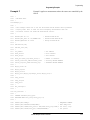
1
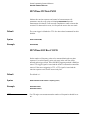
Agilent Technologies 85330A
Multiple Channel Controller
Operating, Programming,
and Service Manual
Part number: 85330-90019
Printed in USA
October 2002
Supersedes November 1999
Notice
Restricted Rights Legend
Use, duplication, or disclosure by the U.S. Government is subject to
restrictions as set forth in subparagraph (c)(1)(ii) of the Rights in Technical
Data and Computer Software clause at DFARS 252.227-7013 for DOD
agencies, and subparagraphs (c)(1) and (c)(2) of the Commercial Computer
Software Restricted Rights clause at FAR 52.227-19 for other agencies.
© Copyright Agilent Technologies, Inc. 1997,1999, 2002
ii
85330A Multiple Channel Controller
What You’ll Find in This Manual…
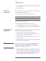
Chapter 1
•
Installation - Shows how a standard Agilent 85330A system is installed.
If you purchased a preconfigured system, Agilent has provided
documentation that contains installation information for your specific
system. Use the documentation for your special system instead of the
information in this chapter.
Chapter 2
•
Performance Verification - Explains how to verify that the 85330A
system is operating properly.
Chapter 3
•
Operator’s Check - This is a quick check of the system to make sure it is
operating properly.
Chapter 4
•
General Information - Describes a typical system, and includes
information on:
❍
❍
❍
❍
❍
❍
❍
Supplied items
Features
85330A connectors
Accessories
Specifications
Environmental Characteristics
Compatible instruments
Chapter 5
•
Manual Operation - Describes functions that can be performed manually
using the multiple channel controller’s front panel softkeys.
Chapter 6
•
Programming - Describes the 85330A programming fundamentals with
examples.
Chapter 7
•
Remote Programming Command Reference - A dictionary of the
85330As programming commands.
Chapter 8
•
In Case of Difficulty - How to solve common system problems.
Chapter 9
•
Service - Explains how to determine if the 85330A specific control cards
are working. This chapter does not explain how to troubleshoot the VXI
mainframe, which has its own service documentaiton.
85330A Multiple Channel Controller
iii
Appendix
•
Glossary of Terms - This glossary defines special terminology
associated with this system. Words shown in bold text are defined in the
glossary.
Warranty
Certification
Agilent Technologies certifies that this product met its published
specifications at the time of shipment from the factory. Agilent further
certifies that its calibration measurements are traceable to the United States
National Institute of Standards and Technology (NIST, formerly NBS), to the
extent allowed by the Institute’s calibration facility, and to the calibration
facilities of other International Standards Organization members.
Documentation
Warranty
THE MATERIAL CONTAINED IN THIS DOCUMENT IS
PROVIDED "AS IS," AND IS SUBJECT TO BEING CHANGED,
WITHOUT NOTICE, IN FUTURE EDITIONS. FURTHER, TO
THE MAXIMUM EXTENT PERMITTED BY APPLICABLE LAW,
AGILENT DISCLAIMS ALL WARRANTIES, EITHER EXPRESS
OR IMPLIED WITH REGARD TO THIS MANUAL AND ANY
INFORMATION CONTAINED HEREIN, INCLUDING BUT NOT
LIMITED TO THE IMPLIED WARRANTIES OF
MERCHANTABILITY AND FITNESS FOR A PARTICULAR
PURPOSE. AGILENT SHALL NOT BE LIABLE FOR ERRORS
OR FOR INCIDENTAL OR CONSEQUENTIAL DAMAGES IN
CONNECTION WITH THE FURNISHING, USE, OR
PERFORMANCE OF THIS DOCUMENT OR ANY
INFORMATION CONTAINED HEREIN. SHOULD AGILENT
AND THE USER HAVE A SEPARATE WRITTEN AGREEMENT
WITH WARRANTY TERMS COVERING THE MATERIAL IN
THIS DOCUMENT THAT CONFLICT WITH THESE TERMS,
THE WARRANTY TERMS IN THE SEPARATE AGREEMENT
WILL CONTROL.
Assistance
Product maintenance agreements and other customer assistance agreements
are available for Agilent products.
For assistance, call your local Agilent Technologies office (refer to “Service
and Support” on page v).
iv
85330A Multiple Channel Controller
Service and Support
Any adjustment, maintenance, or repair of this product must be performed
by qualified personnel. Contact your customer engineer through your local
Agilent Technologies Service Center. You can find a list of local service
representatives on the Web at:
http://www.agilent.com/find/assist
Click on “Contact Us” and select your country.
If you do not have access to the Internet, one of these centers can direct you
to your nearest Agilent Technologies representative:
United States
(800) 403-0801
(800) 593-6635 for on-site service of systems
Canada
(877) 429-9969
Europe
(41 22) 780.6111 (Switzerland)
(33 1) 69 82 66 66 (France)
(49 7031) 464-6222 (Germany)
(44 188) 9696622 (Great Britain)
Japan
0120-32-0119
Latin America
(11) 7297-3700 (Brazil)
Australia/New
Zealand
1-800-802-540 (Australia)
0800-738-378 (New Zealand)
Asia-Pacific
080-047-669
85330A Multiple Channel Controller
v
Safety and Regulatory Information
Review this product and related documentation to familiarize yourself with
safety markings and instructions before you operate the instrument. This
product has been designed and tested in accordance with international
standards.
WARNING
The WARNING notice denotes a hazard. It calls attention to a procedure,
practice, or the like, that, if not correctly performed or adhered to, could result
in personal injury. Do not proceed beyond a WARNING notice until the
indicated conditions are fully understood and met.
CAUTION
The CAUTION notice denotes a hazard. It calls attention to an operating
procedure, practice, or the like, which, if not correctly performed or adhered
to, could result in damage to the product or loss of important data. Do not
proceed beyond a CAUTION notice until the indicated conditions are fully
understood and met.
Instrument Markings
The ON symbol. The ON symbol is used to mark the
positions of the instrument line switch.
The OFF symbol. The OFF symbol is used to mark the
positions of the instrument line switch.
The ON symbol. The ON symbol is used to mark the
positions of the instrument line switch.
The OFF symbol. The OFF symbol is used to mark the
positions of the instrument line switch.
This symbol indicates that the power line switch is OFF or in STANDBY position.
The AC symbol. The AC symbol is used to indicate the
required nature of the line module input power.
The instruction documentation symbol. The product is
marked with this symbol when it is necessary for the user
to refer to the instructions in the documentation.
vi
85330A Multiple Channel Controller
The CE mark is a registered trademark of the European
Community. (If accompanied by a year, it is when the design
was proven.)
The CSA mark is a registered trademark of the Canadian
Standards Association.
This is a symbol of an Industrial Scientific and Medical
Group 1 Class A product.
ICES /
NMB-001
This is a marking to indicate product compliance with the
Canadian Interference-Causing Equipment Standard
(ICES-001).
The C-Tick mark is a registered trademark of the
Australian Spectrum Management Agency.
Safety Earth
Ground
This is a Safety Class I product (provided with a protective earthing
terminal). An uninterruptible safety earth ground must be provided from the
main power source to the product input wiring terminals, power cord, or
supplied power cord set. Whenever it is likely that the protection has been
impaired, the product must be made inoperative and secured against any
unintended operation.
Before Applying Power
Verify that the product is configured to match the available main power
source as described in the input power configuration instructions in this
manual. If this product is to be powered by autotransformer, make sure the
common terminal is connected to the neutral (grounded) side of the ac power
supply.
WARNING
No operator serviceable parts inside. Refer servicing to qualified personnel. To
prevent electrical shock do not remove covers.
WARNING
For continued protection against fire hazard, replace line fuse only with the
same type and ratings (type nA/nV). The use of other fuses or materials is
prohibited.
WARNING
To prevent electrical shock, disconnect the 85330A from mains before
cleaning. Use a dry cloth or one slightly dampened with water to clean the
external case parts. Do not attempt to clean internally.
85330A Multiple Channel Controller
vii
WARNING
If this product is not used as specified, the protection provided by the
equipment could be impaired. This product must be used in a normal condition
(in which all means for protection are intact).
CAUTION
Always use the three-prong ac power cord supplied with this product.
Failure to ensure adequate earth grounding by not using this cord may cause
product damage.
CAUTION
Install the instrument according to the enclosure protection provided. This
instrument does not protect against the ingress of water.
This instrument protects against finger access to hazardous parts with the
enclosure.
viii
85330A Multiple Channel Controller
Manufacturers Declaration
This is to certify that this product meets the radio frequency interference
requirements of Directive FTZ 1046/1984. The German Bundespost has
been notified that this equipment was put into circulation and has been
granted the right to check the product type for compliance with these
requirements.
This product has be designed and tested in accordance with IEC Publication
1010, Safety Requirements for Electronic Measuring Apparatus, and has
been supplied in a safe condition. The instruction documentation contains
information and warnings which must be followed by the user to ensure safe
operation and to maintain the product in a safe condition.
NOTE
If test and measurement equipment is operated with unshielded cables
and/or used for measurements on open set-ups, the user must insure that
under these operating conditions, the radio frequency interference limits are
met at the boarder of his premises.
Hiermit wird bescheinigt, dass dieses Gerät/System in Übereinstimmung mit
den Bestimmungen von Postverfügung 1046/84 funkentstört ist.
Der Deutschen Bundespost wurde das Inverkehrbringen dieses
Gerät/Systems angezeight und die Berechtigung zur Überprüfung der Serie
auf Einhaltung der Bestimmungen eingeräumt.
Zustzinformation für Mess-und Testgeräte:
Werden Mess- und Testgeräte mit ungeschirmten Kabeln und/oder in
offenen Messaufbauten verwendet, so ist vom Betreiber sicherzustellen, dass
die Funk-Entstörbestimmungen unter Betriebsbedingungen an seiner
Grundstücksgrenze eingehalten werden.
Sound Emmisions
This is to declare that this product is in conformance with the German
Regulation on Noise Declaration for Machines (Laermangabe nach der
maschinenlaermrerordnung -3. GSGV Deutschland).
Acoustic Noise Emission
LpA < 70 dB
Operator Position
Normal Position
per ISO 7779
85330A Multiple Channel Controller
Geraeuschemission
LpA < 70 dB
am Arbeitsplatz
normaler Betrieb
nach DIN 45635 t. 19
ix
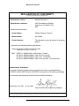
Manufacturers Declaration
DECLARATION OF CONFORMITY
According to ISO/IEC Guide 22 and EN 45014
Manufacturer’s Name:
Hewlett-Packard Co.
Manufacturer’s Address:
1400 Fountaingrove Parkway
Santa Rosa, CA 95403-1799
USA
Declares that the product:
Product Name:
Multiple Channel Controller
Model Number:
HP 85330A
Product Options:
This declaration covers all options of the above
product.
Conforms to the following product specifications:
Safety: IEC 61010-1:1990 / EN 61010-1:1993
CAN/CSA-C22.2 No. 1010.1-92
EMC: CISPR 11:1990/EN 55011:1991 Group 1, Class A
IEC 801-2:1984/EN 50082-1:1992 4 kV CD, 8 kV AD
IEC 801-3:1984/EN 50082-1:1992 3 V/m, 27-500 MHz
IEC 801-4:1988/EN 50082-1:1992 0.5 kV sig. lines, 1 kV power lines
Supplementary Information:
The product herewith complies with the requirements of the Low Voltage Directive
73/23/EEC and the EMC Directive 89/336/EEC and carries the CE-marking accordingly.
The controller was tested with HP 85331A and HP 85332A switches.
Santa Rosa, CA, USA
12 July 1999
Greg Pfeiffer/Quality Engineering Manager
European Contact: Your local Hewlett-Packard Sales and Service Office or Hewlett-Packard GmbH Department HQTRE, Herreneberger Strasse 130, D71034 Boblingen, Germany (FAX +49-7031-14-3143)
x
85330A Multiple Channel Controller
Typeface Conventions
Typeface Conventions
•
Used to emphasize important information:
Use this software only with the Agilent 85330A system.
•
Used for the title of a publication:
Refer to the Agilent Technologies 85330A System-Level User’s
Guide.
•
Used to indicate a variable:
Type LOAD BIN filename.
Instrument Display
•
Used to show on-screen prompts and messages that you will see on the
display of an instrument:
The Agilent xxxxxX will display the message CAL1 SAVED.
[Keycap]
•
Used for labeled keys on the front panel of an instrument or on a
computer keyboard:
Press [Return].
{Softkey}
•
Used for simulated keys that appear on an instrument display:
Press {Prior Menu}.
User Entry
•
Used to indicate text that you will enter using the computer keyboard;
text shown in this typeface must be typed exactly as printed:
Type LOAD PARMFILE
•
Used for examples of programming code:
Italics
#endif // ifndef NO_CLASS
Path Name
•
Used for a subdirectory name or file path:
Edit the file usr/local/bin/sample.txt
Computer Display
•
Used to show messages, prompts, and window labels that appear on a
computer monitor:
The Edit Parameters window will appear on the screen.
•
Used for menus, lists, dialog boxes, and button boxes on a computer
monitor from which you make selections using the mouse or keyboard:
Double-click EXIT to quit the program.
85330A Multiple Channel Controller
xi
Typeface Conventions
xii
85330A Multiple Channel Controller
Contents
Notice . . . . . . . . . . . . . . . . . . . . . . . . . . . . . . . . . . . . . . . . . . . . . . . . . . . . . ii
What You’ll Find in This Manual… . . . . . . . . . . . . . . . . . . . . . . . . . . . . . iii
Warranty . . . . . . . . . . . . . . . . . . . . . . . . . . . . . . . . . . . . . . . . . . . . . . . . . . . iv
Certification . . . . . . . . . . . . . . . . . . . . . . . . . . . . . . . . . . . . . . . . . . . . . iv
Documentation Warranty . . . . . . . . . . . . . . . . . . . . . . . . . . . . . . . . . . . iv
Assistance . . . . . . . . . . . . . . . . . . . . . . . . . . . . . . . . . . . . . . . . . . . . . . . iv
Service and Support . . . . . . . . . . . . . . . . . . . . . . . . . . . . . . . . . . . . . . . . . . v
Safety and Regulatory Information . . . . . . . . . . . . . . . . . . . . . . . . . . . . . . vi
Safety Earth Ground . . . . . . . . . . . . . . . . . . . . . . . . . . . . . . . . . . . . . . vii
Before Applying Power . . . . . . . . . . . . . . . . . . . . . . . . . . . . . . . . . . . vii
Manufacturers Declaration . . . . . . . . . . . . . . . . . . . . . . . . . . . . . . . . . . . . ix
Sound Emmisions . . . . . . . . . . . . . . . . . . . . . . . . . . . . . . . . . . . . . . . . ix
Typeface Conventions . . . . . . . . . . . . . . . . . . . . . . . . . . . . . . . . . . . . . . . xi
1.
Installation
Installation at a Glance . . . . . . . . . . . . . . . . . . . . . . . . . . . . . . . . . . . 1-1
Preparing the Main Antenna Measurement System . . . . . . . . . . . . . . . . 1-2
Installing the Agilent 85330A Multiple Channel Controller . . . . . . . . . 1-2
Choosing the Proper Configuration . . . . . . . . . . . . . . . . . . . . . . . . . 1-2
Checking Operation of the Multiple Channel Controller . . . . . . . . . . . . 1-6
Loading the Driver from a Personal Computer . . . . . . . . . . . . . . . . 1-6
Viewing or Changing the GPIB Address of the Multiple Channel
Controller . . . . . . . . . . . . . . . . . . . . . . . . . . . . . . . . . . . . . . . . . . 1-8
Selecting Positive or Negative-Edge Event Triggers . . . . . . . . . . . . . . . 1-8
Installing the Switch Control Units and Switches . . . . . . . . . . . . . . . . 1-10
Mounting the SCU and RF Switch . . . . . . . . . . . . . . . . . . . . . . . . . 1-10
Switch Control Unit Configuration Switches . . . . . . . . . . . . . . . . . 1-10
2.
Performance Verification
In This Chapter . . . . . . . . . . . . . . . . . . . . . . . . . . . . . . . . . . . . . . . . .
Description . . . . . . . . . . . . . . . . . . . . . . . . . . . . . . . . . . . . . . . . . . . .
Recommended Equipment . . . . . . . . . . . . . . . . . . . . . . . . . . . . . . . .
Performance Verification Test . . . . . . . . . . . . . . . . . . . . . . . . . . . . . . . .
Setting Up the Equipment . . . . . . . . . . . . . . . . . . . . . . . . . . . . . . . . . . . .
85330 System . . . . . . . . . . . . . . . . . . . . . . . . . . . . . . . . . . . . . . . . . .
Digital Oscilloscope . . . . . . . . . . . . . . . . . . . . . . . . . . . . . . . . . . . . .
Network Analyzer . . . . . . . . . . . . . . . . . . . . . . . . . . . . . . . . . . . . . .
Cables . . . . . . . . . . . . . . . . . . . . . . . . . . . . . . . . . . . . . . . . . . . . . . . .
Calibration . . . . . . . . . . . . . . . . . . . . . . . . . . . . . . . . . . . . . . . . . . . .
Save Setup . . . . . . . . . . . . . . . . . . . . . . . . . . . . . . . . . . . . . . . . . . . .
Verifying the Multiple Channel Controller . . . . . . . . . . . . . . . . . . . . . . .
Turn-On . . . . . . . . . . . . . . . . . . . . . . . . . . . . . . . . . . . . . . . . . . . . . .
85330A Multiple Channel Controller
2-1
2-1
2-2
2-3
2-3
2-3
2-4
2-5
2-5
2-5
2-5
2-6
2-6
xiii
Voltage Check . . . . . . . . . . . . . . . . . . . . . . . . . . . . . . . . . . . . . . . . . . 2-6
Inputs/Outputs . . . . . . . . . . . . . . . . . . . . . . . . . . . . . . . . . . . . . . . . . . 2-7
Output Trigger Test . . . . . . . . . . . . . . . . . . . . . . . . . . . . . . . . . . . . . . 2-7
Pulse Receive and Cycle Test . . . . . . . . . . . . . . . . . . . . . . . . . . . . . . 2-8
Counter Pulse Delay Test . . . . . . . . . . . . . . . . . . . . . . . . . . . . . . . . . 2-9
Measurement Busy Signal and Pulse Width Test . . . . . . . . . . . . . . 2-11
Verifying the Switch Control Unit . . . . . . . . . . . . . . . . . . . . . . . . . . . . 2-12
Verifying the RF Switches . . . . . . . . . . . . . . . . . . . . . . . . . . . . . . . . . . . 2-13
Switch Setup . . . . . . . . . . . . . . . . . . . . . . . . . . . . . . . . . . . . . . . . . . 2-13
RF Performance Tests . . . . . . . . . . . . . . . . . . . . . . . . . . . . . . . . . . . 2-14
Verifying Remote Ports 1 and 2 . . . . . . . . . . . . . . . . . . . . . . . . . . . . . . 2-15
Jumpers . . . . . . . . . . . . . . . . . . . . . . . . . . . . . . . . . . . . . . . . . . . . . . 2-15
AUX 1 and AUX 2 . . . . . . . . . . . . . . . . . . . . . . . . . . . . . . . . . . . . . . . . 2-17
Pulse Test . . . . . . . . . . . . . . . . . . . . . . . . . . . . . . . . . . . . . . . . . . . . 2-17
Measuring Pulses from AUX 1 or AUX 2 . . . . . . . . . . . . . . . . . . . 2-17
AUX 1 and AUX 2 Output Voltage Test . . . . . . . . . . . . . . . . . . . . . 2-18
When Finished with All Tests . . . . . . . . . . . . . . . . . . . . . . . . . . . . . 2-18
3.
Operator’s Check
Purpose . . . . . . . . . . . . . . . . . . . . . . . . . . . . . . . . . . . . . . . . . . . . . . . . . . 3-1
Procedure . . . . . . . . . . . . . . . . . . . . . . . . . . . . . . . . . . . . . . . . . . . . . . 3-1
4.
General Information
In This Chapter . . . . . . . . . . . . . . . . . . . . . . . . . . . . . . . . . . . . . . . . . 4-1
Product Description . . . . . . . . . . . . . . . . . . . . . . . . . . . . . . . . . . . . . . 4-2
In-depth Information . . . . . . . . . . . . . . . . . . . . . . . . . . . . . . . . . . . . . 4-2
Manual Operation . . . . . . . . . . . . . . . . . . . . . . . . . . . . . . . . . . . . . . . 4-3
Automated Operation . . . . . . . . . . . . . . . . . . . . . . . . . . . . . . . . . . . . 4-3
Preparing the 85330A to Control the System . . . . . . . . . . . . . . . . . . . . . 4-4
Special Systems . . . . . . . . . . . . . . . . . . . . . . . . . . . . . . . . . . . . . . . . . 4-4
Switch Components . . . . . . . . . . . . . . . . . . . . . . . . . . . . . . . . . . . . . 4-4
The Downloadable Driver . . . . . . . . . . . . . . . . . . . . . . . . . . . . . . . . . 4-5
System Interface . . . . . . . . . . . . . . . . . . . . . . . . . . . . . . . . . . . . . . . . 4-5
Required Equipment . . . . . . . . . . . . . . . . . . . . . . . . . . . . . . . . . . . . . 4-5
Cables . . . . . . . . . . . . . . . . . . . . . . . . . . . . . . . . . . . . . . . . . . . . . . . . 4-5
PIN Switches . . . . . . . . . . . . . . . . . . . . . . . . . . . . . . . . . . . . . . . . . . . 4-7
Supplied Equipment and Software . . . . . . . . . . . . . . . . . . . . . . . . . . . . . 4-8
85330A Multiple Channel Controller Characteristics . . . . . . . . . . . . . . . 4-9
Environmental Limits . . . . . . . . . . . . . . . . . . . . . . . . . . . . . . . . . . . . 4-9
Ventilation Requirements . . . . . . . . . . . . . . . . . . . . . . . . . . . . . . . . 4-10
Dimensions . . . . . . . . . . . . . . . . . . . . . . . . . . . . . . . . . . . . . . . . . . . 4-10
Front Panel Features . . . . . . . . . . . . . . . . . . . . . . . . . . . . . . . . . . . . . . . 4-11
Need More Information . . . . . . . . . . . . . . . . . . . . . . . . . . . . . . . . . . 4-11
Rear Panel Features . . . . . . . . . . . . . . . . . . . . . . . . . . . . . . . . . . . . . . . . 4-12
85330A Compatibility . . . . . . . . . . . . . . . . . . . . . . . . . . . . . . . . . . . . . . 4-15
Compatible Receivers . . . . . . . . . . . . . . . . . . . . . . . . . . . . . . . . . . . 4-15
Compatible LO Sources . . . . . . . . . . . . . . . . . . . . . . . . . . . . . . . . . 4-15
Compatible RF Sources . . . . . . . . . . . . . . . . . . . . . . . . . . . . . . . . . . 4-15
xiv
85330A Multiple Channel Controller
5.
Manual Operation
In This Chapter . . . . . . . . . . . . . . . . . . . . . . . . . . . . . . . . . . . . . . . . .
To Use the Front Panel . . . . . . . . . . . . . . . . . . . . . . . . . . . . . . . . . . . . . .
About the Softkeys Menus . . . . . . . . . . . . . . . . . . . . . . . . . . . . . . . .
Utility Keys . . . . . . . . . . . . . . . . . . . . . . . . . . . . . . . . . . . . . . . . . . . .
Softkey Map . . . . . . . . . . . . . . . . . . . . . . . . . . . . . . . . . . . . . . . . . . . . . .
To View or Change the 85330’s GPIB Address . . . . . . . . . . . . . . . . . . .
Viewing GPIB Address . . . . . . . . . . . . . . . . . . . . . . . . . . . . . . . . . .
Changing the GPIB Address . . . . . . . . . . . . . . . . . . . . . . . . . . . . . .
To Close Any Switch in the System (to select a channel) . . . . . . . . . . .
More about Switch Addresses . . . . . . . . . . . . . . . . . . . . . . . . . . . . .
To Change the TTL State of AUX 1 or AUX 2 . . . . . . . . . . . . . . . . . . .
To View the Most Recent Error Message . . . . . . . . . . . . . . . . . . . . . . . .
To View the Revision of the Downloaded Driver . . . . . . . . . . . . . . . . .
To View Custom Option Number (If Applicable) . . . . . . . . . . . . . . . . .
To Manually Send Trigger Pulses . . . . . . . . . . . . . . . . . . . . . . . . . . . . . .
To Perform Service Functions . . . . . . . . . . . . . . . . . . . . . . . . . . . . . . . .
6.
5-1
5-2
5-2
5-2
5-3
5-4
5-4
5-4
5-5
5-5
5-6
5-6
5-6
5-7
5-7
5-7
Programming
In This Chapter . . . . . . . . . . . . . . . . . . . . . . . . . . . . . . . . . . . . . . . . . 6-1
GPIB Addresses . . . . . . . . . . . . . . . . . . . . . . . . . . . . . . . . . . . . . . . . 6-1
Long and Short Command Syntax . . . . . . . . . . . . . . . . . . . . . . . . . . 6-1
Definition of Terms . . . . . . . . . . . . . . . . . . . . . . . . . . . . . . . . . . . . . . 6-2
To Choose a Measurement Configuration . . . . . . . . . . . . . . . . . . . . . . . 6-3
CW Measurement Configuration . . . . . . . . . . . . . . . . . . . . . . . . . . . . . . 6-4
Description . . . . . . . . . . . . . . . . . . . . . . . . . . . . . . . . . . . . . . . . . . . . 6-4
To Use this Configuration . . . . . . . . . . . . . . . . . . . . . . . . . . . . . . . . . 6-4
Single Source Multiple-Frequency Configuration . . . . . . . . . . . . . . . . . 6-5
Description . . . . . . . . . . . . . . . . . . . . . . . . . . . . . . . . . . . . . . . . . . . . 6-5
To Use this Configuration . . . . . . . . . . . . . . . . . . . . . . . . . . . . . . . . . 6-5
Dual Source Multiple-Frequency Measurements . . . . . . . . . . . . . . . . . . 6-7
8530A Control of Sources . . . . . . . . . . . . . . . . . . . . . . . . . . . . . . . . . . . 6-7
Description . . . . . . . . . . . . . . . . . . . . . . . . . . . . . . . . . . . . . . . . . . . . 6-7
To Use this Configuration . . . . . . . . . . . . . . . . . . . . . . . . . . . . . . . . . 6-7
Fast Source Control . . . . . . . . . . . . . . . . . . . . . . . . . . . . . . . . . . . . . . . . . 6-8
Description . . . . . . . . . . . . . . . . . . . . . . . . . . . . . . . . . . . . . . . . . . . . 6-8
To Use this Configuration . . . . . . . . . . . . . . . . . . . . . . . . . . . . . . . . . 6-8
To Use Direct Control . . . . . . . . . . . . . . . . . . . . . . . . . . . . . . . . . . . . . . . 6-9
Selecting a Channel . . . . . . . . . . . . . . . . . . . . . . . . . . . . . . . . . . . . . 6-9
To Use Run-Time Control Mode . . . . . . . . . . . . . . . . . . . . . . . . . . . . . 6-12
Setup of the 85330A Multiple Channel Controller . . . . . . . . . . . . 6-12
Event Triggering . . . . . . . . . . . . . . . . . . . . . . . . . . . . . . . . . . . . . . . 6-12
Number of Frequency Points . . . . . . . . . . . . . . . . . . . . . . . . . . . . . 6-12
Number of Angular Increments (Events) . . . . . . . . . . . . . . . . . . . . 6-12
List of Switch States . . . . . . . . . . . . . . . . . . . . . . . . . . . . . . . . . . . . 6-12
Switch Settling Time . . . . . . . . . . . . . . . . . . . . . . . . . . . . . . . . . . . 6-13
TTL Trigger and Ready Timeouts . . . . . . . . . . . . . . . . . . . . . . . . . 6-13
85330A Multiple Channel Controller
xv
Using More than One Controller . . . . . . . . . . . . . . . . . . . . . . . . . . .
Starting Run-Time Mode . . . . . . . . . . . . . . . . . . . . . . . . . . . . . . . .
Run-Time Measurement Sequence . . . . . . . . . . . . . . . . . . . . . . . . .
Run-Time Measurement Sequence for Multiple Controllers . . . . .
Using IMM vs. TTL Trigger for Source 1 . . . . . . . . . . . . . . . . . . .
Programming Examples . . . . . . . . . . . . . . . . . . . . . . . . . . . . . . . . . . . . .
Example 1 . . . . . . . . . . . . . . . . . . . . . . . . . . . . . . . . . . . . . . . . . . . .
Example 2 . . . . . . . . . . . . . . . . . . . . . . . . . . . . . . . . . . . . . . . . . . . .
Example 3 . . . . . . . . . . . . . . . . . . . . . . . . . . . . . . . . . . . . . . . . . . . .
85330A Error Messages . . . . . . . . . . . . . . . . . . . . . . . . . . . . . . . . . . . .
7.
6-14
6-14
6-14
6-18
6-18
6-21
6-21
6-25
6-29
6-34
Remote Programming Command Reference
Command Syntax . . . . . . . . . . . . . . . . . . . . . . . . . . . . . . . . . . . . . . . . . . . 7-1
Common Command Format . . . . . . . . . . . . . . . . . . . . . . . . . . . . . . . 7-1
Standard Command Format . . . . . . . . . . . . . . . . . . . . . . . . . . . . . . . 7-1
Common Commands . . . . . . . . . . . . . . . . . . . . . . . . . . . . . . . . . . . . . . . . 7-3
*CLS . . . . . . . . . . . . . . . . . . . . . . . . . . . . . . . . . . . . . . . . . . . . . . . . . . . . 7-3
*IDN? . . . . . . . . . . . . . . . . . . . . . . . . . . . . . . . . . . . . . . . . . . . . . . . . . . . 7-3
*OPC? . . . . . . . . . . . . . . . . . . . . . . . . . . . . . . . . . . . . . . . . . . . . . . . . . . . 7-4
*RST . . . . . . . . . . . . . . . . . . . . . . . . . . . . . . . . . . . . . . . . . . . . . . . . . . . . 7-4
Standard Command Reference . . . . . . . . . . . . . . . . . . . . . . . . . . . . . . . . 7-5
ROUTe . . . . . . . . . . . . . . . . . . . . . . . . . . . . . . . . . . . . . . . . . . . . . . . . . . . 7-5
Subsystem Command Syntax . . . . . . . . . . . . . . . . . . . . . . . . . . . . . . 7-5
ROUTe:CLOSe . . . . . . . . . . . . . . . . . . . . . . . . . . . . . . . . . . . . . . . . . . . . 7-5
ROUTe:CONTrol . . . . . . . . . . . . . . . . . . . . . . . . . . . . . . . . . . . . . . . . . . 7-6
ROUTe:DELay . . . . . . . . . . . . . . . . . . . . . . . . . . . . . . . . . . . . . . . . . . . . 7-6
RUNTime . . . . . . . . . . . . . . . . . . . . . . . . . . . . . . . . . . . . . . . . . . . . . . . . 7-7
RUNTime:CONTroller . . . . . . . . . . . . . . . . . . . . . . . . . . . . . . . . . . . . . . 7-8
RUNTime:EVENt:COUNt . . . . . . . . . . . . . . . . . . . . . . . . . . . . . . . . . . . 7-8
RUNTime:EVENt:TRIGger . . . . . . . . . . . . . . . . . . . . . . . . . . . . . . . . . . 7-9
TTL Mode . . . . . . . . . . . . . . . . . . . . . . . . . . . . . . . . . . . . . . . . . . . . . 7-9
IMM Mode . . . . . . . . . . . . . . . . . . . . . . . . . . . . . . . . . . . . . . . . . . . . 7-9
RUNTime:INITiate:IMM . . . . . . . . . . . . . . . . . . . . . . . . . . . . . . . . . . . 7-10
RUNTime:SOURce:COUNt . . . . . . . . . . . . . . . . . . . . . . . . . . . . . . . . . 7-10
RUNTime:SOURce:SOURCE1:TRIGger . . . . . . . . . . . . . . . . . . . . . . . 7-11
RUNTime:SOURce:SOURCE2:TRIGger . . . . . . . . . . . . . . . . . . . . . . . 7-11
RUNTime:SWITch:DELay . . . . . . . . . . . . . . . . . . . . . . . . . . . . . . . . . . 7-12
RUNTime:SWITch:SCAN . . . . . . . . . . . . . . . . . . . . . . . . . . . . . . . . . . 7-13
RUNTime:SWITch:TRIGger . . . . . . . . . . . . . . . . . . . . . . . . . . . . . . . . 7-14
RUNTime:TIMEout:EVENt . . . . . . . . . . . . . . . . . . . . . . . . . . . . . . . . . 7-15
RUNTime:TIMEout:RECeiver . . . . . . . . . . . . . . . . . . . . . . . . . . . . . . . 7-15
RUNTime:TIMEout:REMote . . . . . . . . . . . . . . . . . . . . . . . . . . . . . . . . 7-16
RUNTime:TIMEout:SOURce . . . . . . . . . . . . . . . . . . . . . . . . . . . . . . . . 7-16
SYSTem . . . . . . . . . . . . . . . . . . . . . . . . . . . . . . . . . . . . . . . . . . . . . . . . . 7-16
SYSTem:ERRor? . . . . . . . . . . . . . . . . . . . . . . . . . . . . . . . . . . . . . . . . . . 7-17
8.
In Case of Difficulty
The 85330A Does Not Show the Main Menu When Turned ON . . . . . 8-11
xvi
85330A Multiple Channel Controller
9.
Service
Introduction . . . . . . . . . . . . . . . . . . . . . . . . . . . . . . . . . . . . . . . . . . . 9-1
Theory of Operation . . . . . . . . . . . . . . . . . . . . . . . . . . . . . . . . . . . . . . . . 9-2
Recommended Test Equipment . . . . . . . . . . . . . . . . . . . . . . . . . . . . . . . 9-8
Service . . . . . . . . . . . . . . . . . . . . . . . . . . . . . . . . . . . . . . . . . . . . . . . . . . . 9-9
Troubleshooting . . . . . . . . . . . . . . . . . . . . . . . . . . . . . . . . . . . . . . . . . . 9-10
Troubleshooting the System . . . . . . . . . . . . . . . . . . . . . . . . . . . . . . 9-10
Troubleshooting the Multiple Channel Controller . . . . . . . . . . . . . 9-10
Troubleshooting the Switch Control Unit . . . . . . . . . . . . . . . . . . . 9-11
Troubleshooting the RF Switch . . . . . . . . . . . . . . . . . . . . . . . . . . . 9-11
Troubleshooting the Cables . . . . . . . . . . . . . . . . . . . . . . . . . . . . . . 9-11
Replaceable Parts . . . . . . . . . . . . . . . . . . . . . . . . . . . . . . . . . . . . . . . . . 9-14
Parts List Description . . . . . . . . . . . . . . . . . . . . . . . . . . . . . . . . . . . 9-14
Ordering Information . . . . . . . . . . . . . . . . . . . . . . . . . . . . . . . . . . . 9-14
Replaceable Parts . . . . . . . . . . . . . . . . . . . . . . . . . . . . . . . . . . . . . . 9-14
Mainframe, Plug-in Cards . . . . . . . . . . . . . . . . . . . . . . . . . . . . . . . 9-16
Switch Control Unit . . . . . . . . . . . . . . . . . . . . . . . . . . . . . . . . . . . . 9-17
RF Switch . . . . . . . . . . . . . . . . . . . . . . . . . . . . . . . . . . . . . . . . . . . . 9-17
Interconnect Cables . . . . . . . . . . . . . . . . . . . . . . . . . . . . . . . . . . . . 9-18
Assembly and Disassembly . . . . . . . . . . . . . . . . . . . . . . . . . . . . . . . . . 9-19
Mainframe . . . . . . . . . . . . . . . . . . . . . . . . . . . . . . . . . . . . . . . . . . . 9-19
E1330 Card Configuration . . . . . . . . . . . . . . . . . . . . . . . . . . . . . . . 9-20
85330-60002 Card Configuration . . . . . . . . . . . . . . . . . . . . . . . . . . 9-20
Switch Control Unit . . . . . . . . . . . . . . . . . . . . . . . . . . . . . . . . . . . . 9-21
Adjustments . . . . . . . . . . . . . . . . . . . . . . . . . . . . . . . . . . . . . . . . . . . . . 9-22
Selecting Positive or Negative-Edge Event Triggers . . . . . . . . . . . 9-22
Selecting the Multiple Channel Controller’s GPIB Address . . . . . 9-23
Switching from the Internal to External Power Supply . . . . . . . . . 9-24
Preventive Maintenance . . . . . . . . . . . . . . . . . . . . . . . . . . . . . . . . . . . . 9-25
10.
Accessory Documentation
11.
Glossary
85330A Multiple Channel Controller
xvii
-xviii 85330A Multiple Channel Controller
Installation
1
Installation
Installation at a
Glance
The installation procedure is composed of the following basic steps:
1. If you just purchased an antenna measurement system, install all
components as described in the documentation that came with that
system. Do not connect the Agilent 85330A yet.
2. Turn on the system and perform a functional check.
3. If desired, verify the performance of the system components by referring
to the Performance Verification chapter of the system manual.
4. Install and verify the 85330A system as explained in this manual.
85330A Multiple Channel Controller
1-1
Installation
Preparing the Main Antenna Measurement System
Preparing the Main Antenna Measurement
System
CAUTION
As an antistatic precaution, do not touch exposed connector contacts!
Information about installing, performing an operational check, and verifying
the main antenna measurement system is explained in the appropriate
documentation listed below:
•
•
•
Agilent 85301B Antenna Measurement System Manual
Agilent 85301C Antenna Measurement System Manual
Agilent 85310A Distributed Frequency Converter Manual
If you purchased an Agilent 8511 as a stand-alone unit, refer to the Agilent
8530A On-Site Service Manual for installation instructions. Verify the 8511
as explained in its operating and service manual.
Installing the Agilent 85330A Multiple Channel
Controller
Choosing the Proper
Configuration
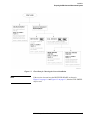
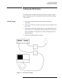
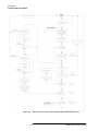
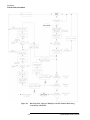
There are two ways to install the Agilent 85330A system. Figure 1-1 on
page 1-3 is a flow chart that shows a installation configuration that is
appropriate for you to use.
How to use the figure
Follow the flow chart from the top. Determine if your measurements are
made with a single frequency (CW), or multiple frequencies. Proceed down
the appropriate flow chart path. Proceed in this way until you get to a box
that recommends either Figure 1-2 on page 1-4, or Figure 1-3 on page 1-5.
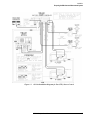
Fast Source Control
Fast source control speeds up frequency switching speed in
multiple-frequency measurements. It is only available in systems that use
two Agilent 836xx series synthesized sources. This mode uses TTL signals
to increment RF and LO source frequency, providing faster frequency
switching speeds than are possible under 8530A control. In the fast source
control configuration, the system’s computer must set up the sources with
appropriate frequency settings, triggering mode, and so on. When automatic
Run Time measurement mode is engaged, the 85330A automatically
increments the RF and LO source frequencies using TTL lines. More
information is provided in Chapter 6, “Programming.” When the sources are
controlled by a computer, the SCPI language mode must be selected. This is
shown in Figure 1-3 on page 1-5.
1-2
85330A Multiple Channel Controller
Installation
Preparing the Main Antenna Measurement System
Figure 1-1
NOTE
Flow Chart for Choosing the Correct Installation
If the receiver does not have the RECEIVER READY, as shown in
Figure 1-2 on page 1-4 and Figure 1-3 on page 1-5, then the STOP SWEEP
may be used.
85330A Multiple Channel Controller
1-3
Installation
Preparing the Main Antenna Measurement System
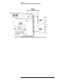
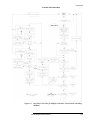
Figure 1-2
85330A Installation Diagram for 8530A Source Control
1-4
85330A Multiple Channel Controller
Installation
Preparing the Main Antenna Measurement System
Figure 1-3
85330A Installation Diagram for Fast (TTL) Source Control
85330A Multiple Channel Controller
1-5
Installation
Checking Operation of the Multiple Channel Controller
Checking Operation of the Multiple Channel
Controller
Turn the multiple channel controller ON; the following screen should
appear:
Select an instrument._
SYSTEM 85330A IBASIC (see
NOTE
note below)
IBASIC is only present if the IBASIC option is installed.
If the display shows “DIG I/O” instead of “85330A”, then the drivers are no longer
loaded.
If you do not see this display, load the VXI mainframe downloadable driver
files as explained in “Loading the Driver from a Personal Computer,” next.
The 85330A contains 85330A driver files from the disk labeled 85330A
Downloadable Driver Disk. When your system was shipped, the driver files
were already loaded into the non-volatile memory of the 85330A
mainframe. Once loaded, it will remain when the mainframe is powered
down or when the power is interrupted to the mainframe.
If you must reload the drivers, a complete set of instructions are included in
the INSTALL.TXT file on the supplied driver disk, or perform the following
instructions:
NOTE
This method uses a personal computer (PC) to download the drivers over a
serial cable (supplied).
NOTE
The downloadable driver disk should not be set to the write-protected
position or the driver files will not load properly.
Loading the Driver
from a Personal
Computer
Equipment Needed
The following equipment was supplied with your system:
•
•
•
1-6
Serial Cable: 24542U part number 24540-80014, 9-pin to 9-pin
Adapter: 1252-7577, 9-pin to 25-pin (only needed if your computer has
a 25-pin serial connector)
Downloadable Driver Disk: p/n 85330-10016 (rev A.02.31 or higher)
85330A Multiple Channel Controller
Installation
Checking Operation of the Multiple Channel Controller
NOTE
You can use other com ports, such as com2. However, you have to edit a file
called “VXIDLD.CFG” so the software knows you are using a different port.
This configuration file can be edited with any ASCII text editor, such as
notepad. Save the changed file back to the supplied disk.
NOTE
Agilent recommends that you make two backups of the driver disk. Make
one copy to a floppy disk, and one copy to the personal computer used with
the system.
Procedure
NOTE
This procedure may not work on later versions of Microsoft®1 Windows®
such as Windows NT® and Windows 2000®.
1. Disconnect any GPIB cables from the mainframe. If it is easier, you can
disconnect the GPIB from the back of the system controller computer.
2. Turn the VXI mainframe ON.
3. On your PC, open a DOS command prompt window.
4. Insert the supplied driver disk into drive A. (Do not write-protect the
downloadable driver disk. The driver will not load if the write-protect
window is open. Make sure the tab is snapped fully into the closed
portion.)
5. In the DOS command prompt window, change to drive A.
6. In the DOS command prompt window, type VXIDLD and press [Enter].
7. The mainframe download procedure takes approximately six or seven
minutes, and the mainframe will reboot.
NOTE
There are several error messages that can be ignored. These are described in
the README.TXT file on the driver disk. Specifically, refer to the
description of the VXIDLD.CFG file.
8. Reconnect all the GPIB cables.
9. When finished, the following should be displayed:
Select an instrument._
SYSTEM 85330A IBASIC (see
NOTE
1
note below)
IBASIC is only present if the IBASIC option is installed.
Microsoft, Windows, Windows NT, and Windows 2000 are U.S. registered trademarks of Microsoft Corporation.
85330A Multiple Channel Controller
1-7
Installation
Selecting Positive or Negative-Edge Event Triggers
Viewing or Changing
the GPIB Address of
the Multiple Channel
Controller
The factory default setting of the GPIB address is 9. To view the GPIB
address:
Press [Select Instr] {SYSTEM} {GPIB} {READ}.
To change the current GPIB address:
1. Press [Select Instr] {SYSTEM} {GPIB} {SET}.
2. Enter the new address and press [Return].
Selecting Positive or Negative-Edge Event
Triggers
By default, the positive-edge of the EVENT TRIG line starts the
measurement. To change this so a negative-edge starts the measurement,
perform the following procedure.
CAUTION
This device contains devices that are sensitive to static discharge. When you
remove the cover of this device, observe static safety precautions:
1. Place the unit on a grounded anti-static mat.
2. Wear a grounded wrist strap. Foot straps are only acceptable if you wear
one on each foot, and if you are standing on a grounded floor mat.
Refer to Figure 1-4 on page 1-9.
1-8
85330A Multiple Channel Controller
Installation
Selecting Positive or Negative-Edge Event Triggers
Figure 1-4
Positive/Negative-Edge EVENT TRIG jumpers
1. Remove the two screws that hold the E1330B board in place.
2. Remove the four screws that hold the 85330-60002 board in place.
3. Pull out the two boards at the same time. You can do this by pulling each
one out a little at a time, until they are both removed. Place the boards
on an anti-static surface.
Standard positive-edge operation is set at the factory by jumpering
E9 and E10 together.
4. To select negative-edge operation, move the jumper across E9 and E8.
5. Reinstall the boards and screws.
85330A Multiple Channel Controller
1-9
Installation
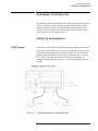
Installing the Switch Control Units and Switches
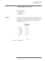
Installing the Switch Control Units and Switches
Mounting the SCU and
RF Switch
If desired, you can mount the SCU using the supplied mounting screws. You
must provide a mounting plate or drill holes in an existing structure before
mounting an SCU or a switch. Refer to the mounting diagram in Figure 1-5
on page 1-11.
NOTE
Make sure the 85383A local control cable can reach from the multiple
channel controller to the SCU. Make sure the 85384A switch drive cable is
long enough to reach from the SCU to the switch.
Switch Control Unit
Configuration
Switches
Changing any of the DIP switches inside the SCU is not recommended. All
switch settings are made at the factory.
In a standard system (defined below), the following settings are used:
•
•
SCU address is set to 0.
Channel numbers 1 through 4 are used to select switch positions.
A “standard system” uses one 85330A with one or two switch control units,
each with a two-throw or four-throw switch module. Remember that 85330A
PORT 1 and PORT 2 are addressed independently. So:
•
•
1-10
If you have two SCUs, both can use the default SCU address (0).
You can use the default channel number assignments (1 through 4) for
both switch modules. Since each SCU is on a different port, and each
port is addressed independently, there is not a channel number conflict.
85330A Multiple Channel Controller
Installation
Installing the Switch Control Units and Switches
Figure 1-5
SCU and Switch Mounting Diagram
85330A Multiple Channel Controller
1-11
Installation
Installing the Switch Control Units and Switches
1-12
85330A Multiple Channel Controller
Performance Verification
2
Performance Verification
In This Chapter
•
•
•
•
Description
This performance verification should be done once a year, or more
frequently as needed. This procedure verifies that the Agilent 85330A
system meets or exceeds its published specifications. Specifications are
listed in Chapter 4, “General Information.” If traceability to a local standards
organization is required, then it can be done with this procedure. One such
standards organization is the United States National Institute of Standards
and Technology (NIST, formerly NBS).
Recommended performance verification test equipment
Performance verification tests
Verifying the multiple channel controller
Verifying the RF switches
This verification can be performed at the measurement system’s site, or at a
service bench. The verification will verify all parts of the multiple channel
system: multiple channel controller, switches, and cables. This verification
does not check the performance of the measurement system’s transmitter or
receiver. Use the measurement system’s manual for more information on
that procedure.
85330A Multiple Channel Controller
2-1
Performance Verification
Recommended
Equipment
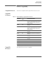
Table 2-1 lists the equipment that is mandatory when performing the
performance verification.
Table 2-1
Required Equipment
Qty
Item
Agilent Part or Model Number1
1
Downloadable Driver Disk, rev A.03.00
85330-100162
1
Multimeter (20 Vdc, digital)
E2377A
1
Digital Oscilloscope (100 MHz bandwidth
1 MHz Single-shot bandwidth)
54501A
1
Tee adapter (BNC male to female, female)
1250-0781
3
Cable (BNC male to male 122 cm)
8120-1840
1
Network Analyzer System3
(50 MHz to 40 GHz4, 5
90 dB dynamic range)
8722C (Option 003)
1
Plotter or Printer6
HP 7550A+, or LaserJet
1
Torque wrench (2.4/3.5 mm @ 8 in-lb)
8710-17657
1. Other part numbers or model numbers may be used if they meet the minimum requirements.
2. Included with 85330A shipment.
3. System must include vector network analyzer, test port cables, and a calibration kit.
4. A 50 MHz to 26.5 GHz network analyzer may be used if the 3.5 mm adapters are used with the
microwave switches.
5. If a network analyzer is used with a frequency range less than the switches, the performance
verification will only be valid over the frequency range of the network analyzer.
6. Plotter or printer must be connected to the network analyzer and oscilloscope for test documentation.
7. Use this wrench for any 2.4/3.5 /SMA mm connections in this procedure.
2-2
85330A Multiple Channel Controller
Performance Verification
Performance Verification Test
Performance Verification Test
The following verification procedure will verify the Agilent 85330 system in
two parts. The first part will verify the operation of the multiple channel
controller to make sure that it is controlling the switches and the receiver
correctly. The second part will check the switch’s RF performance and to
make sure that they are switching correctly.
Setting Up the Equipment
85330 System
Connect the 85330 system to the switch control unit using the correct local
control cable. This should be set up the same way that the 85330A system is
used in the measurement system (Agilent 85301B/C). Do not connect the
Switch Control Units (SCU) to their switches at this time. Do not connect
the 85330A to any other instruments in the measurement system. An
example of a setup is shown in Figure 2-1. Do not turn ON the 85330A at
this time.
Figure 2-1
An Example Performance Verification Setup
85330A Multiple Channel Controller
2-3
Performance Verification
Performance Verification Test
Digital Oscilloscope
Set up the Agilent 54503A digital oscilloscope (or any oscilloscope) as
described in the following procedure, using the same settings.
NOTE
The oscilloscope setup described in the following procedure will not display
a trace on the oscilloscope screen until a pulse is initiated. The oscilloscope
will then hold the trace until the [CLEAR DISPLAY] is pressed.
Procedure
Turn ON the oscilloscope and press the following keys on the 54503A:
[CHAN]: {1}
{ON}
{2v/Div}
{Offset: 0v}
{Coupling: DC}
{Input: 1 M Ω}
{Probe Ratio: 1:1}
[CHAN]: {2}
{ON}}
{2v/Div}
{Offset: 5v}
{Coupling: DC}
{Input: 1 M Ω}
{Probe Ratio: 1:1}
[TRIG]:
{Trig’d}
{Edge}
{Source: 1}
{Adjust: 1v}
{
} (- Edge)
[TIMEBASE]:
{2 us/Div}
{Delay: 0}
{Reference: Cntr}
[SAVE] [1]
2-4
85330A Multiple Channel Controller
Performance Verification
Performance Verification Test
Network Analyzer
Turn ON the vector network analyzer. Adjust the controls for the following
setup:
Measurement Display
Display:
4 Channel
Channel 1:
S11
SWR
Channel 2:
S21
Log Mag
Channel 3:
S12
Log Mag
Channel 4:
S22
SWR
Domain:
Frequency
Start Frequency:
45 MHz
Stop Frequency:
40 GHz
Number of Points:
201
RF Source Power:
Maximum
Measurement:
Continuous
Averaging:
As required
Set up the rest of the measurement display for your convenience and ease of
viewing.
Cables
Connect one test port cable to Port 2 of the test set. The RF switch will be
connected directly to the test set Port 1. An example of this setup is shown in
Figure 2-1, “An Example Performance Verification Setup,” on page 2-3.
Calibration
Perform a full, two port calibration at the test set Port 1, and at the end of the
test port cable connected to Port 2.
Save Setup
Save this instrument state setup in Save/Recall register 1. It will be used later
in the tests. Press:
[SAVE] {1}
85330A Multiple Channel Controller
2-5
Performance Verification
Verifying the Multiple Channel Controller
Verifying the Multiple Channel Controller
This portion of the verification will check the 85330 multiple channel switch
controller to ensure that it is operating correctly. It will also check the
Switch Control Unit of the Agilent 85331/2 to make sure that it is switching
correctly. Document the test results by plotting or printing the test
instrument screens as each test is performed.
Turn-On
Turn the multiple channel controller ON; the following screen should
appear:
Select an instrument._
SYSTEM
NOTE
85330A
IBASIC
(see note below)
IBASIC is only present if the IBASIC option is installed.
If you see the above display, the unit has passed its turn on tests and is
working properly. If you do not see this display, load the 85330A
downloadable driver files as explained in the “Loading the Driver from a
Personal Computer” on page 1-6.
Voltage Check
Check the voltage on the switch control unit’s OUTPUT connector. This is
the connector that is used to daisy-chain the switch control units together.
The voltages are shown in Table 2-2. If an external power supply is used to
bias the switch control units, the supply may require some adjustment to
keep the voltage within the tolerances.
Table 2-2
Switch Control Unit Voltages
Pin
Voltage
E, L, V
+12 ±1.8 Vdc
a
−12 ±1.8 Vdc
F, M, W, b
ground
2-6
85330A Multiple Channel Controller
Performance Verification
Verifying the Multiple Channel Controller
Figure 2-2
Inputs/Outputs
Switch Control Unit Output Connector Voltages
Press the following on the multiple channel controller:
[Clear Instr] [Select Instr]
You should see the following display:
Select an instrument._
SYSTEM
NOTE
85330A
IBASIC
(see note below)
IBASIC is only present if the IBASIC option is installed.
This is the MAIN MENU.
Output Trigger Test
The following test will determine if the rear-panel ports output the correct
signals. Note that a single press on the specific {TRIGGER} key will cause a
single trigger pulse. If you hold down this key, a train of trigger pulses will
be outputted.
1. Connect a BNC cable between Channel 1 of the oscilloscope and the
multiple channel controller rear panel BNC connector that is being
tested.
2. On the oscilloscope, press:
[RECALL] [1]
3. Connect the BNC cable to the RCVR TRIG connector on the multiple
channel controller, and press:
{85330A} {TRIGGER} {RCVR}
On the oscilloscope, press [CLEAR DISPLAY]. You should see a negative
pulse, with an approximate width of one to three microseconds.
4. Connect the BNC cable to the SRC 1 TRIG connector on the multiple
channel controller, and press:
{SRC_1}
85330A Multiple Channel Controller
2-7
Performance Verification
Verifying the Multiple Channel Controller
On the oscilloscope, press [CLEAR DISPLAY]. Set the [TIMEBASE] to {5 us/Div}.
You should see a positive pulse, with an approximate width of 10 to 14
microseconds.
5. Connect the BNC cable to the SRC 2 TRIG connector on the multiple
channel controller, and press:
{SRC_2}
On the oscilloscope, press [CLEAR DISPLAY]. You should see a positive
pulse, with an approximate width of 10 to 14 microseconds.
6. Remove the BNC cable from the multiple channel controller.
Pulse Receive and
Cycle Test
The following test will determine if the rear panel ports successfully sense
the trigger pulses. These tests will output a train of 100 pulses.
1. Press the following on the multiple channel controller:
[Clear Instr] [Select Instr] {85330A}
2. Connect a BNC cable between the RCVR READY and RCVR TRIG
connectors. Press:
[More] {TEST} {RCVR} [1] [0] [0] [Return]
If the test is successful, the RCVR menu will appear on the display. If
the test fails, the following error message will appear:
-214, Trigger deadlock
3. Connect a BNC cable between the SRC1 READY and SRC1 TRIG
connectors. Press:
{SRC_1} [1] [0] [0] [Return]
If the test is successful, the RCVR menu will appear on the display. If
the test fails, the following error message will appear:
-214, Trigger deadlock
4. Connect a BNC cable between the SRC2 READY and SRC2 TRIG
connectors. Press:
{SRC_2} [1] [0] [0] [Return]
If the test is successful, the RCVR menu will appear on the display. If
the test fails, the following error message will appear:
-214, Trigger deadlock
5. Remove the BNC cable from the multiple channel controller.
2-8
85330A Multiple Channel Controller
Performance Verification
Verifying the Multiple Channel Controller
Counter Pulse Delay
Test
The following test determines if the on-board counter is operating correctly.
1. Connect BNC cables between the SRC1 TRIG, RCVR READY
connectors and the oscilloscope as shown in Figure 2-3 on page 2-10.
2. On the oscilloscope press:
[RECALL] [1]
[TRIG] {Source 2} {Adjust: 1.5v} {
}
(+ Edge}
[TIMEBASE] {1 us/Div} {Delay: 4 us} {Ref: Centr}
[SAVE] [2]
3. Press the following on the multiple channel controller:
[Clear Instr] [Select Instr] {85330A} {RESET} [More] {TEST} {COUNTER}
4. Press the following on the multiple channel controller:
[4] [Return]
5. The negative edge of the displayed pulse should be 4 ±1 microseconds.
To use the scope measurement feature, press: [∆t ∆v] {∆t Marker: ON}.
Rotate the front panel knob until the vertical marker line intersects the
negative edge of the pulse. Note that the Start Marker reading will be the
pulse delay. See Figure 2-4 on page 2-10 for more information.
6. On the oscilloscope press:
[TIME BASE] {1 us/Div} {Delay: 1000 us} [CLEAR DISPLAY]
7. Press the following on the multiple channel controller:
[1] [0] [0] [0] [Return]
8. The negative edge of the displayed pulse should be 1,000 ±
1 microseconds.
To use the scope measurement feature, press: [∆t ∆v] {∆t Marker: ON}.
Rotate the front panel knob until the vertical marker line intersects the
negative edge of the pulse. Note that the Start Marker reading will be the
pulse delay. See Figure 2-4 for more information.
9. On the oscilloscope press:
[TIME BASE] {2 us/Div} {Delay: 15 ms} [CLEAR DISPLAY]
10. Press the following on the multiple channel controller:
[1] [5] [0] [0] [0] [Return]
11. The negative edge of the displayed pulse should be 15 ± 0.001
milliseconds.
To use the scope measurement feature, press: [∆t ∆v] {∆t Marker: ON}.
Rotate the front panel knob until the vertical marker line intersects the
85330A Multiple Channel Controller
2-9
Performance Verification
Verifying the Multiple Channel Controller
negative edge of the pulse. Note that the Start Marker reading will be the
pulse delay. See Figure 2-4 for more information.
12. Remove the BNC cables.
Figure 2-3
Counter Pulse Delay Test Setup
Figure 2-4
15 millisecond Delay Trigger Example
2-10
85330A Multiple Channel Controller
Performance Verification
Verifying the Multiple Channel Controller
Measurement Busy
Signal and Pulse
Width Test
The following test will determine if the MEAS BUSY port output pulse
width is correct. It will also test the EVENT TRIG input.
1. Connect a BNC cable between the SRC1 TRIG and EVENT TRIG
connectors.
2. Connect a BNC cable between the MEAS BUSY connector and the
oscilloscope channel 1.
3. On the oscilloscope press:
[TIME BASE] {10 us/Div} [CLEAR DISPLAY]
4. Press the following on the multiple channel controller:
[Clear Instr] [Select Instr] {85330A} [More] {TEST} {EVENT} [1] [Return]
5. While the measurement is cycling, observe the MEAS BUSY pulse on
the oscilloscope. The pulse width should be approximately 50
microseconds.
6. If the test is successful the RCVR menu will appear on the display. If the
test fails, the following error message will appear:
-214, Trigger deadlock
85330A Multiple Channel Controller
2-11
Performance Verification
Verifying the Switch Control Unit
Verifying the Switch Control Unit
This test will determine if the multiple channel controller is controlling the
Switch Control Unit and that the SCU is operating correctly. If the system
has move than one SCU on a single port, then check each SCU.
1. Check to make sure that the multiple channel controller is connected to
each switch control unit. An example of this setup is shown in
Figure 2-5 on page 2-13.
2. Check each switch control unit. The Active light should be ON.
3. Press the following on the multiple channel controller:
[Clear Instr] [Select Instr] {85330A} {CLOSE}
4. Select {PORT 1} or {PORT 2} depending on the setup of your switch system.
If your system uses both PORT 1 and PORT 2, then perform the
following tests for both ports:
a. Press:
{PORT 1}
or {PORT 2}
b. Enter each switch control unit’s address and switch number and
observe that unit’s lights. As each switch address is activated, the
light should turn ON.
To enter a unit address and switch number, press:
[x] [y] [z] [Return]
x = switch control unit’s address (normally 0)
y = switch number to be closed (normally 0)
z = switch number to be closed (0 = opens all switches)
For example, {PORT 1} [1] [0] [3] [Return] will close switch 3 in the switch
control unit with address 1 that is connected to PORT 1. The switch
control unit address can be found on the units label. To close switch 4,
just press [1] [0] [4].
c. Close each switch on a module and insure that the light turns ON.
5. Perform the above test for each Switch Control Unit in the system.
2-12
85330A Multiple Channel Controller
Performance Verification
Verifying the RF Switches
Verifying the RF Switches
This portion of the verification will check the switches to make sure that
they are switching correctly. This portion will also test the RF performance
of the switches.
Switch Setup
1. Turn OFF the multiple channel controller before making any
connections.
2. Connect each switch to its switch control unit. Use the supplied switch
drive cable.
3. Connect the switch to the network analyzer. An example of this setup is
shown in Figure 2-5. Note that all of the switch ports will be tested, so
make sure that there is enough room to connect all of the ports to the
network analyzer.
4. Turn ON the multiple channel controller.
Figure 2-5
RF Switch Test Setup
85330A Multiple Channel Controller
2-13
Performance Verification
Verifying the RF Switches
RF Performance Tests
Recall the network analyzer setup that was saved earlier by pressing:
[RECALL] {1}
Perform each of the following tests on each input and output port of the
switch. Check the results of each of the tests against the switch’s
specifications shown in the Agilent 85331A/Agilent 85332A User’s Manual.
1. Connect the test port cable to the first switch port.
2. Close the switch path. This will turn the switch light ON on the switch
control unit.
a. Check the S11 (input match, ON).
b. Check the S22 (output match, ON).
c. Check the S21 (insertion loss, ON).
d. Check the S12 (reverse insertion loss, ON).
e. Document the test results by plotting the display to a plotter or
printer.
3. Open the switch path. This will turn the switch light OFF on the switch
control unit.
a. Check the S11 (input match, OFF).
b. Check the S22 (output match, OFF).
c. Check the S21 (isolation, OFF). Use averaging if required.
d. Check the S12 (reverse isolation, OFF). Use averaging if required.
e. Document the test results by plotting the display to a plotter or
printer.
4. Move the test port cable to the next switch port. Repeat all of the above
until all switch ports are tested.
2-14
85330A Multiple Channel Controller
Performance Verification
Verifying Remote Ports 1 and 2
Verifying Remote Ports 1 and 2
Equipment Required
•
•
•
Jumpers
Jumper (see below)
Soldering iron
2 jumper wires
Figure 2-6 shows the jumper assembly that can be used to verify remote port
1 and remote port 2. Using Agilent part number 1251-8863, solder one wire
from pin 6 to pin 8, and another wire from pin 7 to pin 9. A connector hood
is recommended for the 9-pin connector, such as L-com (part number
SDC9AG) (http://www.L-com.com).
Figure 2-6
Jumper Assembly
85330A Multiple Channel Controller
2-15
Performance Verification
Verifying Remote Ports 1 and 2
Remote Port 1 and remote Port 2 Test Procedure
1. Download the 85330A drivers version A.03.00 or above.
2. When select instrument is displayed, press:
{85330A}, {More}, {TEST}, {More}
3. Connect the modified connector to REMOTE 1 on the rear panel and
press:
{REM_1_2}
4. The display should read:
“85330A_144:REM1 0101 PASS, REM2 1100 FAIL”
5. Move the modified connector to REMOTE 2 on the rear panel and
press:
{REM_1_2}
6. The display should read:
“85330A_144: REM1 1111 FAIL, REM2 0011 PASS”
2-16
85330A Multiple Channel Controller
Performance Verification
AUX 1 and AUX 2
AUX 1 and AUX 2
Pulse Test
You can output one or more 500 µs pulses from AUX 1 or AUX 2 and
measure them with an oscilloscope. The number of pulses is selectable. The
pulses have a 50% duty cycle, and thus a total period of 1 ms. The amplitude
of the signal is roughly 0 to 4 volts. The pulses are not perfect square waves.
The leading edge rises higher than 4 volts, then curves down to
approximately 4 volts.
Measuring Pulses from
AUX 1 or AUX 2
1. Connect an oscilloscope to the AUX 1 or AUX.
2. Set the scope as necessary to view the waveform described above.
3. Press:
[Select Instr] {85330A}
{→} {TEST} {→} {AUX 1} or {AUX 2}
4. The message TEST AUXn OUTPUT: # OF TESTS will appear.
5. Use the keyboard to enter the desired number of pulses. You can enter
the number in units or in scientific notation: For example:
100, or
1E2
6. Press the [Return] key. The pulses will appear on the scope.
NOTE
The 85330A will not perform any other functions during this test. If you
enter a large number, such as 1E6, it will take a while to finish. You can
abort the test by cycling line power.
NOTE
To test AUX 2, use the same basic procedure as shown above.
85330A Multiple Channel Controller
2-17
Performance Verification
AUX 1 and AUX 2
AUX 1 and AUX 2
Output Voltage Test
The following test will determine if the rear panel ports successfully output
the correct DC switch drive levels.
1. On the oscilloscope press:
[RECALL] [1]
[TRIG] {AUTO}
[CLEAR DISPLAY]
2. Press the following on the multiple channel controller:
[Clear Instr] [Select Instr] {85330A}
3. Connect a BNC cable between the AUX 1 connector and channel 1 of
the oscilloscope.
a. Press:
{CLOSE} {AUX1} {0}
or [f1]
The oscilloscope should show a trace of about 0 Vdc.
b. Press:
{1}
or [f2]
The oscilloscope should show a trace of about 4 Vdc.
4. Connect a BNC cable between the AUX 2 connector and channel 1 of
the oscilloscope.
a. Press:
[Clear Instr] {CLOSE} {AUX2} {0}
or [f1]
The oscilloscope should show a trace of about 0 Vdc.
b. Press:
{1}
or [f2]
The oscilloscope should show a trace of about 4 Vdc.
When Finished with
All Tests
All of the performance verification tests are now complete. Reconnect the
85330A system in the original measurement system configuration. Refer to
Chapter 1, “Installation” for more information.
2-18
85330A Multiple Channel Controller
Operator’s Check
3
Operator’s Check
Purpose
This operator’s check verifies that the Agilent 85330A can close switches,
showing that the 85330A, switch control units, and switches are working.
You can perform this check daily, or as desired. This is not a performance
verification procedure (refer to Chapter 2, “Performance Verification” for
more information).
Procedure
This procedure asks you to close every switch in your standard system, and
look for an appropriate signal with the measurement system.
1. Press: [Select Instr] {85330A}.
2. If the {CLOSE} softkey does not appear, press [Prev Menu] until it does.
3. Press: {CLOSE}
a. If the switch you want to close is connected to SWITCH PORT 1,
press {PORT_1}.
b. If the switch you want to close is connected to SWITCH PORT 2,
press {PORT_2}.
4. Enter the switch address using the numeric keypad. In a standard
system, simply enter the channel number (1, 2, 3, or 4), and press
[Return]. If you have a custom system, refer to Chapter 5, “Manual
Operation” for instructions.
5. Look at the channel LEDs on the front of the switch control unit. The
light for the selected channel should be ON. This shows that the SCU is
responding properly.
6. Perform a measurement with your system. The measurement system
should be able to measure any signal present on the selected channel.
7. Repeat these steps for each channel on each switch port.
85330A Multiple Channel Controller
3-1
Operator’s Check
3-2
85330A Multiple Channel Controller
General Information
4
General Information
In This Chapter
•
•
•
•
•
•
•
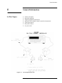
Figure 4-1
Product description
Required equipment
Supplied equipment and software
Agilent 85330A multiple channel controller characteristics
Front panel features
Rear panel features
AC power cord
85330A System Overview
85330A Multiple Channel Controller
4-1
General Information
Product Description
The Agilent 85330A multiple channel controller adds high-speed
multiple-channel measurement capability to Agilent 8530A-based
automated measurement systems, using high-isolation solid state microwave
switch modules. The 85330A is a run time controller that orchestrates the
sequencing and synchronizing of all the required functions for
multiple-channel and multiple-frequency measurements, to allow very fast
data acquisition speed and data throughput of the measurement system.
•
Option 908 - Rack Mount Kit Without Handles
Multiple Channel Controller rack mount kit without handles. To obtain
this item after receiving the 85330A, order part number 5062-3978.
•
Option 913 - Rack Mount Kit With Handles
Multiple Channel Controller rack mount kit with handles. To obtain this
item after receiving the 85330A, order part number 5062-3984.
•
Option 910 - Additional Manual
This provides an additional manual. To obtain this item after receiving
the 85330A, order part number 85330-90019.
In-depth Information
Measurement Speed Advantages
The multiple channel controller, when used with the Autoranged Fast Data
Acquisition mode, provides very fast measurement speeds. Even faster
measurements can be made when the RF/LO sources are controlled using
the direct TTL source control capabilities of the multiple channel controller.
Frequency states can be downloaded to the Agilent 8360 series of frequency
synthesizers. The multiple channel controller sends TTL triggers to the
sources (in two-source systems) at the appropriate time to change their
frequency. This method maximizes the frequency agility of the system by
allowing the sources to switch at their fastest rate.
Triggering
The 85330A receives triggers from the positioning system, and synchronizes
the data acquisition to the positioning system. It also controls the triggering
of the microwave receiver, and sequencing of the multiple channel data into
the receiver.
Lowering the Workload on the Computer Controller
When using 85330A as the system controller, the demands of the computer
are decreased during run-time. The computer is free to collect data from the
receiver and perform data manipulation, display, and storage.
4-2
85330A Multiple Channel Controller
General Information
Installing the Detachable Power Cord
Install the instrument so that the detachable power cord is readily
identifiable and is easily reached by the operator. The detachable power cord
is the instrument disconnecting device. It disconnects the mains circuits
from the mains supply. The front panel switch is only a standby switch and
is not a LINE switch. Alternatively, an externally installed switch or circuit
breaker (which is readily identifiable and is easily reached by the operator)
may be used as a disconnective device.
Manual Operation
Front panel softkeys allow you to:
•
•
•
•
•
View or change the 85330A’s GPIB address.
Close any switch in the system (select a channel).
Change the TTL state of AUX 1 or AUX 2.
View the revision of the downloaded driver.
Perform service functions.
Refer to Chapter 5, “Manual Operation,” for more information.
Automated Operation
During automated operation, the 85330A can control switches in two ways:
Direct Control
Run Time
Mode
The 85330A can directly control switch states
and issue triggers using GPIB commands.
Using GPIB commands, the 85330A
can be set up for a specific measurement sequence,
then automatically execute that measurement
(run-time mode).
85330A Multiple Channel Controller
4-3
General Information
Preparing the 85330A to Control the System
Preparing the 85330A to Control the System
Configuring the 85330A is composed of the following steps:
1. Send the 85330A a series of GPIB setup commands prior to starting the
run-time sequence.
2. Start the run-time sequence by sending a specific GPIB command.
3. The 85330A then waits for a positioner trigger signal to begin the
sequence.
4. The 85330A repeats the sequence for the specified number of frequency
points to be measured.
More detailed information on this subject is explained in Chapter 6,
“Programming.”
Special Systems
Switch Components
Special system configurations allow you to:
•
Daisy-chain SCUs to provide many channels with a single multiple
channel controller.
•
Add remote multiple channel controllers to expand the switch tree or
extend the physical distance that switches can be placed from the control
room. Additional remote multiple channel controllers can be up to
2 Kilometers away from the master.
The 85330A controls the following items:
Switch control units
In standard systems, the system interface board communicates with one or
two SCUs. SCUs perform the following tasks:
•
They decode binary information from the multiple channel controller to
determine which switch should be closed.
•
They provide the necessary bias voltages to the switches, which causes
them to switch states.
In a standard system, one SCU is connected to the multiple channel
controller’s PORT 1 connector, and the other SCU is connected to PORT 2.
The separate ports provide the ability to put switches at the transmit and
receive site.
4-4
85330A Multiple Channel Controller
General Information
Preparing the 85330A to Control the System
PIN switch modules
The switches are broadband, high-isolation switches. Each switch is
supplied with a switch control unit. Specifications and performance
characteristics are provided in the Agilent 85331A and Agilent 85332A PIN
Switch User’s Manual.
The Downloadable
Driver
The multiple channel controller cannot perform tasks until programming
instructions are supplied. These instructions specify:
•
•
How to interact with the control boards installed in its rear panel slots.
•
The GPIB programming commands that setup and control the multiple
channel controller.
The softkey menu interface and the functions performed by each
softkey.
This driver is supplied by Agilent and is loaded into the multiple channel
controller at the factory. If you must ever re-load the driver, refer to the
instructions provided in Chapter 5, “Manual Operation.”
System Interface
A system interface board (85330-60002) is installed in the back of the
multiple channel controller. This board contains the TTL trigger and ready
lines that interface to the receiver, switch control units, and (if using Fast
Source Control) the RF and LO sources.
Required Equipment
The following equipment is required in addition to the 85330A:
Cables
•
The cables that connect the 85330A, switch control units and switch
modules.
•
One or more 85331A or 85332A PIN switch. The switches include their
associated switch control unit.
85383A Local Control Cable
Provides the connection between the multiple channel controller and each
SCU. Cable length is determined at the time of order by selecting the
appropriate length option.
•
•
•
•
•
•
•
Option 002:
Option 005:
Option 010:
Option 020:
Option 030:
Option 040:
Option 050:
2 meters
5 meters
10 meters
20 meters
30 meters
40 meters
50 meters
85330A Multiple Channel Controller
4-5
General Information
Preparing the 85330A to Control the System
Table 4-1
Agilent 85383 Wiring Table
D-Type
Connector Pins
Circular
Connector Pins
D-Type
Connector Pins
Circular
Connector Pins
1
A
14
K
2
C
15
R
3
B
16
S
4
D
17
X
5
E
18
T
6
L
19
Y
7
NC1
20
U
8
F
21
Z
9
M
22
V
10
H
23
a
11
N
24
W
12
J
25
b
13
P
1. NC = No Connection
85383B expansion cable
Allows SCUs to be daisy-chained together to create expanded switch
matrices. Only 0.5 m cables are available.
85384A Switch Driver Cable
Provides the connection between SCUs and switch modules. Cable length is
determined at time of order by selecting the appropriate length option.
•
•
•
•
Option 001:
Option 002:
Option 005:
Option 010:
1 meter
2 meters
5 meters
10 meters
85385A Remote Trigger Cable
Is a twisted-pair cable which allows you to connect a remote multiple
channel controller. Cable lengths up to 2 Kilometers are available.
4-6
85330A Multiple Channel Controller
General Information
Preparing the 85330A to Control the System
PIN Switches
The 85331A SP2T PIN Switch
The 85331A SP2T PIN switch consists of two modules:
•
•
A switch control unit (SCU)
A high-speed high-isolation SP2T microwave switch module
The 85332A SP4T PIN Switch
Identical to the 85331A except that the 85332A uses a SP4T switch module.
85330A Multiple Channel Controller
4-7
General Information
Supplied Equipment and Software
Supplied Equipment and Software
Table 4-2
Supplied Equipment and Software
Item
Quantity
Part or Model Number
Multiple channel controller
1
85330A
Downloadable driver disk Rev A.03.00
1
85330-10016
Operating and Service Manual
1
85330-90019
E1301A/B Getting Started Guide
1
E1300-90004
E1302A User’s Manual
1
E1300-90005
9-pin to 25-pin adapter
1
1252-7577
RS-232 Cable
1
24542U p/n 24540-80014
E1330A/B Users Manual
1
E1330-90004
ac power cord
1
Depends on Destination Country
4-8
85330A Multiple Channel Controller
General Information
85330A Multiple Channel Controller Characteristics
85330A Multiple Channel Controller
Characteristics
This product is designed for use in Installation Category II and Pollution
Degree 2 per IEC 1010 and 664 respectively.
CAUTION
Before switching on this instrument, make sure the line voltage selector
switch is set to the voltage of the mains supply and the correct fuse is
installed. Ensure the supply voltage is in the specified range.
Environmental Limits
Table 4-3
Environmental Conditions for the 85330A
Temperature:
For Operation
For Storage
+0 to +55 °C (32 to 131 °F)
−40 to +70 °C (−40 to 158 °F)
Humidity:
For Operation
Pressure Altitude:
For Operation or Storage
Power Requirements:
Line Voltage
Fused at
Power Consumption:
85330A only
85330A + 85331A (all off)
85330A + 85332A (all off)
85330A + 2 85332As (all off)1
5% to 95% at +40 °C or less (non condensing)
5% to 95% at +65 °C or less (non condensing)
Less than 4,600 meters (15,000 feet)
115 or 230 Vac 50 to 400 Hz
3 A at 115 Vac
1.5 A at 230 Vac
78 VA
88 VA
92 VA
107 VA
1. This is the worst case for a standard system.
85330A Multiple Channel Controller
4-9
General Information
85330A Multiple Channel Controller Characteristics
Ventilation
Requirements
CAUTION
When installing the product in a cabinet, the convection into and out of the
product must not be restricted. The ambient temperature (outside the
cabinet) must be less than the maximum operating temperature of the
product by 4 °C for every 100 watts dissipated in the cabinet. If the total
power dissipated in the cabinet is greater than 800 watts, then forced
convection must be used.
Dimensions
Table 4-4
Size and Dimensions
Height without feet
177 mm
6.97 in
Height with feet
189 mm
7.44 in
Width
426 mm
16.75 in
Depth
510 mm
20.1 in
Depth with terminal blocks
569 mm
22.38 in
Net weight
≈ 11.8 kg
≈ 26 lbs
4-10
85330A Multiple Channel Controller
General Information
Front Panel Features
Front Panel Features
The front panel contains:
•
•
•
Need More
Information
A 2-line by 40 character display.
A QWERTY keyboard, plus utility keys.
Five software-controlled display softkeys.
Refer to the following locations for more information:
•
Refer to Chapter 5, “Manual Operation,” for more information. This
chapter also describes the tasks you can perform manually with the
85330A.
•
“Using the Front Panel” in the Agilent 75000 Series B Mainframes
User’s Manual.
85330A Multiple Channel Controller
4-11
General Information
Rear Panel Features
Rear Panel Features
Figure 4-2
85330A Rear Panel Connectors
EVENT TRIG
By default, this input accepts a positive or negative-edge TTL trigger from
the positioner controller or other device. The default is positive-edge
triggering. The trigger signal initiates a measurement sequence. Connect
EVENT TRIG to the positioner controller or other TTL trigger source.
You can configure the 85330A so it responds to a negative-edge TTL trigger
signal. Refer to Chapter 1, “Installation,” for instructions.
MEAS BUSY
Goes TTL HIGH when the EVENT TRIG line is asserted. This line stays
HIGH during the measurement sequence, going LOW after the measurement
sequence is finished. This line is designed to tell external control logic when
the measurement system is busy, and using it is optional.
RCVR TRIG
Sends a 2 to 3 µs negative-edge pulse to the EVENT TRIGGER input of the
receiver. This causes the receiver to acquire data. The number of parameters
measured by a single trigger pulse is determined by how the receiver
measurement controls are set up. A single parameter (radioed measurement
point) is taken in the FASC, FASD, FASAD (Fast Data Acquisition) modes,
and multiple parameters are measured if you are using the FASMUX mode.
4-12
85330A Multiple Channel Controller
General Information
Rear Panel Features
The multiple channel controller may send several receiver trigger pulses
during the measurement sequence, depending on the instructions you sent to
it before starting the run-time mode.
RCVR READY
This positive-edge signal is sent by the receiver when it finished acquiring
data. This line connects to the RECEIVER READY line on the receiver.
AUX 1
Provides a user-controllable TTL line for special applications. The state of
AUX 1 must be set before entering the 85330A’s automatic run-time mode.
The state of AUX 1 is controlled with the ROUTe:CONTrol command.
AUX 2
Provides a user-controllable TTL line for special applications. The state of
AUX 2 can be set in two ways:
•
•
Before entering run-time mode using the ROUTe:CLOSe command.
During run-time using RUNTime:SWITch:SCAN command.
SRC 1 TRIG
Used in conjunction with SRC 1 READY, controls frequency switching in
the RF source much faster than is possible under 8530A control.This
connects to the TRIGGER IN line of the RF source.
SRC 1 READY
Used in conjunction with SRC 1 TRIG, controls frequency switching in the
RF source much faster than is possible under 8530A control. This connects
to the TRIGGER OUT line of the RF source.
SRC 2 TRIG
Used in conjunction with SRC 2 READY, controls frequency switching in
the LO source much faster than is possible under 8530A control. This
connects to the TRIGGER IN line of the LO source.
SRC 2 READY
Used in conjunction with SRC 2 TRIG, controls frequency switching in the
LO source much faster than is possible under 8530A control. This connects
to the TRIGGER OUT line of the LO source.
REMOTE 1 and 2
These connectors are used to add remote multiple channel controllers in
custom systems—they are not used with the standard instrument.
85330A Multiple Channel Controller
4-13
General Information
Rear Panel Features
SWITCH PORT 1 and 2
Connects to either of the two switch control units (SCUs). These ports
provide binary data for switch control as well DC power.
AUX POWER IN
This connector is not used with the standard instrument.
4-14
85330A Multiple Channel Controller
General Information
85330A Compatibility
85330A Compatibility
Compatible Receivers
The 85330A is compatible with the Agilent 8530A microwave receiver.
Compatible
LO Sources
Table 4-5
Compatible
RF Sources
Required Options for Agilent 836xx LO Sources
Model Number
Recommended
Options
83620A/B
008
83620As with a serial prefix less than 3103A require
Option H87. If cable length between the LO source and
85309A is greater than 7 meters, contact your local
Agilent representative.
83621A/B
None
83621As with a serial prefix less than 3103A require
Option H87.
83622A/B
008
83622As with a serial prefix less than 3103A require
Option H87. If cable length between the LO source and
85309A is greater than 7 meters, contact your local
Agilent representative.
83623A/B
008
83623As with a serial prefix less than 3103A require
Option H87.
83624A/B
008
83624As with a serial prefix less than 3103A require
Option H87.
83630A/B
008
83630As with a serial prefix less than 3103A require
Option H87.
83631A/B
None
83630As with a serial prefix less than 3103A require
Option H87.
83640A/B
008
None
83642A
008
None
83650A/B
008
None
83651A/B
None
None
Special Option Requirements
Any Agilent 836xx series source is compatible.
85330A Multiple Channel Controller
4-15
General Information
85330A Compatibility
4-16
85330A Multiple Channel Controller
Manual Operation
5
Manual Operation
This chapter describes how to manually operate the Agilent 85330A
multiple channel controller.
In This Chapter
•
•
•
•
•
•
•
•
•
To use the front panel
Softkey map
To view or change the 85330A’s GPIB address
To close any switch in the system (to select a channel)
To change the TTL state of AUX 1 or AUX 2
To view the most recent error message
To view the revision of the downloaded driver
To manually send triggers pulses
To perform service functions
85330A Multiple Channel Controller
5-1
Manual Operation
To Use the Front Panel
To Use the Front Panel
This is an overview of main front panel features. For more information, refer
to “Using the Front Panel” in Chapter 2 of the Agilent 75000 Series B
Mainframes Agilent E1300A and E1301A/B User’s Manual
The front panel contains:
•
•
•
About the Softkeys
Menus
A 2-line by 40 character display
A QWERTY keyboard, plus utility keys mentioned below
Five software-controlled display softkeys
The 85330A’s softkey menus behave differently than those in a network
analyzer or microwave receiver. Each of the top-level menu items {SYSTEM}
{85330A} and {IBASIC} (IBASIC is present only if the IBASIC option is
installed) are treated as if they were independent instrument personalities.
When you leave a certain menu and return to it later, you start at the exact
point you left off.
For example:
1. Press [Select Instr] {85330A} and press {CLOSE}.
2. Now leave the 85330A menu by pressing [Select Instr] {SYSTEM}.
3. Return to the 85330A menu by pressing [Select Instr] {85330A}. Notice that
the CLOSE function reappears, not the top level of the 85330A menu.
Utility Keys
[Select Instr]
This presents the two different instrument personalities, SYSTEM and
85330A. When you select an instrument, you are assigning the keyboard and
display to that instrument. This means that any menu operations, commands
executed or recalled, error displayed, for example. pertain only to that
instrument. Front panel operation of an instrument is independent from other
instruments and independent of the remote operation of the instrument.
[Prev Menu]
This key presents the previous softkey menu.
[More]
When there are more than five menu choices, an arrow appears on the right
side of the display. Press [More] to display the next group of choices. This key
also displays the next 40 characters in a long display message.
5-2
85330A Multiple Channel Controller
Manual Operation
Softkey Map
Softkey Map
Figure 5-1
NOTE
85330A Softkey Menu Map
Refer to Chapter 3 of the Agilent 75000 Series B Mainframes Agilent
E1300A and E1301A/B User’s Manual.
85330A Multiple Channel Controller
5-3
Manual Operation
To View or Change the 85330’s GPIB Address
To View or Change the 85330’s GPIB Address
Viewing GPIB Address
The factory default setting of the GPIB address is 9.
To view the GPIB address:
Press:
[Select Instr] {SYSTEM} {GPIB} {READ}
Changing the GPIB
Address
To change the current GPIB address:
1. Press:
[Select Instr] {SYSTEM} {GPIB} {SET}
2. Enter the new address and press:
[Return]
5-4
85330A Multiple Channel Controller
Manual Operation
To Close Any Switch in the System (to select a channel)
To Close Any Switch in the System
(to select a channel)
To manually close a switch (to select a channel):
1. Press:
[Select Instr] {85330A}
2. If the {CLOSE} softkey does not appear, press:
[Prev Menu]
(until it does)
3. Press:
{CLOSE}
a. If the switch you want to close is connected to PORT 1, press
{PORT_1}
b. If the switch you want to close is connected to PORT 2, press
{PORT_2}
4. Enter the switch address using the numeric keypad. In a standard
system, simply enter the channel number (1, 2, 3, or 4), and press [Return].
More about Switch
Addresses
The “switch address” is a concatenation of the Switch Control Unit (SCU)
address (set to 0 at the factory) with the channel number (in “standard”
systems this number is 1, 2, 3, or 4).
If you just enter the channel number (1, 2, 3, or 4), the multiple channel
controller will assume that the SCU address is still at the factory default (0).
Changing SCU address requires DIP switch changes inside the SCU, and is
not necessary in standard systems. To select switch 1 (channel 1), just press
[1] [Return].
In custom systems with many switches, a different SCU address might be
used in part of the switch tree. Here are some example switch addresses for
complex switch trees:
101 (SCU address 1, channel 01)
212 (SCU address 2, channel 12)
312 (SCU address 3, channel 12)
Notice in the first example (101) that a two digit channel number (01) was
required. When the SCU address is set to 1, 2 or 3, you must enter a
two-digit channel number – even for channels 1 through 9.
85330A Multiple Channel Controller
5-5
Manual Operation
To Change the TTL State of AUX 1 or AUX 2
To Change the TTL State of AUX 1 or AUX 2
To set AUX 1 or AUX 2 TTL state:
1. Press:
[Select Instr] {85330A}
2. If the {CLOSE} softkey does not appear, press [Prev Menu] until it does.
3. Press:
{CLOSE}
4. Press:
{AUX_1}
or {AUX_2}
5. Press {0} for TTL LOW or {1} for TTL HIGH.
To View the Most Recent Error Message
1. To view the most recent error message, press:
[Select Instr] {85330A}
2. If the {ERROR?} softkey does not appear, press
[Prev Menu]
(until it does)
3. Press: {ERROR?}
To View the Revision of the Downloaded Driver
1. To view the revision of the downloaded driver, press:
[Select Instr] {85330A}
2. If the {REV?} softkey does not appear, press
[Prev Menu] (until
it does)
3. Press: {REV?}
4. Press the [→] key to view the entire revision message.
5-6
85330A Multiple Channel Controller
Manual Operation
To View Custom Option Number (If Applicable)
To View Custom Option Number (If Applicable)
Some 85330As are equipped with custom driver s as required by the
customer. Pressing:
[Select Instr]
Rev
Opt?
then [More] the display will read:
Test.
Click on Opt?
This presents the custom option number (if any) for the driver.
To Manually Send Trigger Pulses
To manually issue a trigger to the receiver (EVENT TRIGGER), RF or LO
source (TRIGGER IN):
1. Press:
[Select Instr] {85330A}
2. If the {TRIGGER} softkey does not appear, press
[Prev Menu] (until
it does)
3. Press {TRIGGER}, followed by:
{RCVR}
to send a trigger to the receiver.
{SRC_1}
to send a trigger to the RF source.
{SRC_2}
to send a trigger to the LO source.
To Perform Service Functions
Service functions are located under the {85330) {→} {TEST} softkey menu. They
are not described in this chapter. Refer to “Verifying the Multiple Channel
Controller” on page 2-6 for more information.
85330A Multiple Channel Controller
5-7
Manual Operation
To View Custom Option Number (If Applicable)
5-8
85330A Multiple Channel Controller
Programming
6
Programming
In This Chapter
This chapter provides a general programing of the operation for the Agilent
85330A and a detailed description of the programming codes. Several
scenarios and examples are given.
•
•
•
•
•
•
GPIB Addresses
GPIB addresses
Definition of terms
To choose a measurement configuration
To use Direct control
To use run-time control mode
Programming examples
Using GPIB commands, the 85330A can be set up prior to run-time followed
by an GPIB command to pass run-time control to the 85330A. This is called
run-time control mode. The 85330A can also directly control switch states
and issue triggers using GPIB commands. This is called direct control.
BASIC is used for all examples. To address the 85330A, a secondary GPIB
address is needed. In most cases the complete GPIB address would be
70918:
•
•
•
Long and Short
Command Syntax
“7” refers to the select code of the GPIB address.
“09” is the GPIB address of the 85330A multiple channel controller.
“18” is the secondary address of the E1330A/B DIO card. This is a
board that is inside the multiple channel controller.
The GPIB commands have a long and short form. The upper-case characters
represent the short form and the complete set of characters represent the long
form. Example, ROUTe:CLOSe is the complete or long from of the GPIB
command while the abbreviated or short form is ROUT:CLOS.
85330A Multiple Channel Controller
6-1
Programming
Definition of Terms
NOTE
Please review the following terms before reading information in this chapter.
SCU address
At the factory, each Switch Control Unit is assigned an address called an
SCU address. When commands are sent out port 1 or port 2, they only affect
SCUs with the specified SCU address. SCU addresses are set using DIP
switches inside the SCU, and can be set to 0, 1, 2, or 3. In a standard system,
the factory default setting is 0. For custom-designed systems, refer to the
documentation that came with that system for SCU address numbers.
Daisy-chained SCUs may use the same SCU address.
Channel
Each switch module has either two or four possible switch positions, or
channels. If you purchased a switching system designed by Agilent, you also
have received a manual that applies specifically to that switch tree. That
document shows the channel numbers for each switch. If you have
purchased a “standard” system, then channels 1 through 4 are the factory
default channel numbers. (Channels 3 and 4 only apply to four-throw
switches.)
NOTE
Ports 1 and 2 are addressed independently. Because of this, there are no
addressing conflicts when using two SCUs—even if they use the same SCU
address and channel numbers.
Switch address
This is the complete software address for a specific switch. It is simply a
concatenation of the SCU address (0, 1, 2, or 3) with the channel number
(usually 1, 2, 3, or 4, but possibly a number up to 64 in custom systems).
Examples:
@103 = SCU address 1 and channel 3 selected.
@2 = SCU address is 0 (and need not be specified), and channel 2 is
selected.
@232 = SCU address is 2 and channel 32 is selected (custom systems only).
The port number (1 or 2) is specified separately, as is explained later in this
chapter.
6-2
85330A Multiple Channel Controller
Programming
To Choose a Measurement Configuration
To Choose a Measurement Configuration
The measurement configuration you use depends on the type of
measurement (CW or multiple-frequency) and the type of system
(one-source or two-source system). One-source systems use the Agilent
8511A/B frequency converter, two-source systems use the Agilent 85309A
frequency converter.
Refer to Figure 6-1.
How to Use the Figure
Follow the flow chart from the top. Determine if your measurements are
made with a single frequency (CW) or multiple frequencies. Proceed down
the appropriate flow chart path. Proceed in this way until you get to a box
that mentions one of the following headings:
•
•
•
•
CW Measurement Configuration
Single Source Multiple-Frequency Configuration
8530A Control of Sources
Fast Source Control
Proceed to the section indicated to read about that specific configuration.
Figure 6-1
Flow Chart for Finding the Correct Configuration
85330A Multiple Channel Controller
6-3
Programming
CW Measurement Configuration
CW Measurement Configuration
Description
In single-frequency measurements, the Fast Source Control mode is not
used. The RF source (and LO source, if used) can either be controlled by:
•
•
The 8530A (set the sources to Analyzer Language mode), or...
The system computer (set the sources to SCPI Language mode).
Refer to the programming “Example 1” on page 6-21.
To Use this
Configuration
The proper setup is shown in Figure 1-2 on page 1-4. Use the 8530A Fast
Autoranging Data Mode (GPIB command: FASAD), explained in Chapter 8 of
the Agilent 8530A User’s Guide.
6-4
85330A Multiple Channel Controller
Programming
Single Source Multiple-Frequency Configuration
Single Source Multiple-Frequency Configuration
Description
In single-source (8511A/B based) systems, the Fast Source Control mode is
not available. The RF source is controlled by the 8530A (Analyzer
Language mode). The proper setup is shown in Figure 1-2 on page 1-4.
The Fast Data Acquisition modes of the 8530A cannot be used with this type
of measurement. Instead, the multiple parameter display of the 8530A is
used to measure each switch input.
Refer to the programming “Example 2” on page 6-25.
NOTE
When using the multiple parameter display feature, the minimum switch
settling time (RUNT:SWIT:DEL) is 50 µs. Using shorter settling times in
multiple parameter display mode can cause measurement problems
To Use this
Configuration
Here is an overview of how measurements are made in this configuration.
Remember, GPIB commands must be immediately followed by a semicolon
when entered into an actual program. For example NUMEB1;.
8530A settings
•
Select multiple parameter display mode on the 8530A. The number of
parameters selected should equal the number of test signals you are
measuring. For example, assume you have a two-throw receive switch
connected to two test signals. In this case, program the 8530A for two
parameter display GPIB command TWOP. This is the equivalent of
pressing [DISPLAY] {DISPLAY MODE} {TWO PARAMETER}.
•
Set each parameter to measure the same input ratio. For example, set
them all to measure b1/a1. The numerator and the denominator are
defined below:
❍
The numerator is the input port (of the frequency downconverter)
that is connected to the common port of the receive switch. Set this
using the GPIB NUMEB1, NUMEB2, NUMEA1, or NUMEA2 command. This is
equivalent to pressing PARAMETER {MENU} {REDEFINE PARAMETERS}
{NUMERATOR}, then {NUMERATOR: b1}, {NUMERATOR: b2}, {NUMERATOR: a1}, or
{NUMERATOR: a2}.
❍
The denominator is the input port that is connected to the reference
signal. Use the DENOA1, DENOA2, or DENOB1 command. This is
equivalent to pressing PARAMETER {MENU} {REDEFINE PARAMETERS}
{DENOMINATOR}, then {DENOM.: a1}, {DENOM.: a2}, or {DENOM.: b1}.
85330A Multiple Channel Controller
6-5
Programming
Single Source Multiple-Frequency Configuration
This setup allows the 8530A to measure each receive switch input in
sequence. Each one is measured as a separate parameter, which you can read
using the system computer. Refer to the GPIB Programming chapter of the
Agilent 8530A Operating and Programming Manual for detailed
information.
•
Select external triggering with TRGEXT. This is equivalent to pressing
STIMULUS {MENU} {MORE} {TRIGGER MODE} {TRIG SRC EXTERNAL}. This
command is described in the Stimulus chapter of the Agilent 8530A
Operating and Programming Manual.
•
Set the 8530A so it waits for a trigger before measuring each parameter.
You can do this by issuing PAR1TON, PAR2TON, PAR3TON, and PAR4TON. This
is equivalent to pressing STIMULUS {MENU} {MORE} {TRIGGER MODE}, then
ensuring that {PARAM 1}, {PARAM 2}, {PARAM 3}, and {PARAM 4} are activated
(underlined). These commands are described in the Stimulus chapter of
the Agilent 8530A Operating and Programming Manual.
You only have to send the PARTON commands that relate to the parameters
that are actually being measured. For example, if you are only measuring
Parameter 1 and Parameter 2, PAR1TON and PAR2TON are the only two
commands that must be executed.
NOTE
You can issue all four of these commands even if you are measuring only
two or three parameters. The extra commands will simply be ignored.
85330A settings
•
When the source is under 8530A control, the multiple channel controller
must be set to the IMMediate triggering mode:
RUNT:SOUR:SOURCE1:TRIG IMM;
•
6-6
Use GPIB address 19 for the RF source.
85330A Multiple Channel Controller
Programming
Dual Source Multiple-Frequency Measurements
Dual Source Multiple-Frequency Measurements
When you are using multiple-frequency measurements with an 85309A
frequency converter, you can choose how the sources are controlled:
•
•
You can allow the 8530A to control source frequency switching, or...
You can use the Fast Source Control configuration, where source
frequency switching is controlled by the multiple channel controller.
8530A Control of Sources
Description
If you choose to control source frequency switching with the 8530A (and
you are using the dual source multiple-frequency configuration), you cannot
use the Fast Data Acquisition modes of the receiver. Refer to the
programming “Example 2” on page 6-25.
To Use this
Configuration
Operation in this mode is nearly identical to that described in “Single Source
Multiple-Frequency Configuration” on page 6-5. When the sources are
under 8530A control, the multiple channel controller must be set to the
IMMediate triggering mode:
RUNT:SOUR:SOURCE1:TRIG IMM;
RUNT:SOUR:SOURCE2:TRIG IMM;
Use GPIB address 19 for the RF source, and 18 for the LO source.
85330A Multiple Channel Controller
6-7
Programming
Fast Source Control
Fast Source Control
Description
Fast source control speeds up frequency switching speed in
multiple-frequency measurements. It is only available in 85309A-based
systems. This mode uses TTL signals to increment RF and LO source
frequency, providing faster frequency switching speeds than are possible
under 8530A control.
Refer to the programming “Example 3” on page 6-29.
To Use this
Configuration
In the fast source control configuration, the system’s computer must set up
the sources with appropriate frequency settings, triggering mode, and so on.
When automatic run-time measurement mode is engaged, the 85330A
automatically increments the RF and LO source frequencies using TTL
lines. When being controlled by a computer, the SCPI language mode must
be selected. This is shown in Figure 1-3 on page 1-5.
Fast Data Acquisition can be used in this configuration. Use the 8530A Fast
Autoranging Data Mode (GPIB command: FASAD), as explained in Chapter 8
of the Agilent 8530A User’s Guide.
8530A settings
In the 8530A Local menu, the addresses for Source 1 and Source 2 must be
set to 31. This tells the 8530A that it cannot communicate with the sources.
85330A settings
Since the 8530A does not control the sources, set the multiple channel
controller to TTL triggering mode:
RUNT:SOUR:SOURCE1:TRIG TTL;
RUNT:SOUR:SOURCE2:TRIG TTL;
Source settings
•
•
Use Frequency List or Step mode.
Sweep Point Trigger must be set to EXT:
SWE:TRIG:SOUR EXT;
•
Start Sweep Trigger must be set to AUTO:
TRIG:SOUR IMM;
The Sweep Point Trigger and Start Sweep Trigger settings allow external
triggers from the 85330A to trigger the sources.
6-8
85330A Multiple Channel Controller
Programming
To Use Direct Control
To Use Direct Control
Direct control is where the host computer issues GPIB commands and the
85330A executes them immediately. For example, the ROUTe:CLOSe
(port number) (switch address) command causes the 85330A to immediately
change switch states.
Selecting a Channel
Here are examples of how to select a channel.
Example 1, for a standard system
OUTPUT 70918; “ROUT:CLOS 1,(@2);”
Switch port 1, default SCU address (0), channel 2 selected.
In this example, the BASIC OUTPUT command is used to output a command
to the 85330A. The command, ROUT:CLOS 1,(@2); is sent to GPIB address
70918 (the 85330A). This command string would:
•
•
Activate switch port 1.
•
Select channel 2.
Address the SCU (which is set at the factory to SCU address 0). Since
the default address is being used, the SCU address is not required, and is
not specified in the command.
Example 2, for a typical custom system
OUTPUT 70918; “ROUT:CLOS 2,(@110);”
Switch port 2, SCU address 1, channel 10
The command ROUT:CLOS 2,(@110); is sent to GPIB address 70918 (the
85330A). This command string would:
•
•
•
Activate switch port 2.
Address any SCU, or SCUs, at SCU address 1.
Select channel 10. “110” is the switch address and is defined as the
concatenation of the SCU address and the channel number.
85330A Multiple Channel Controller
6-9
Programming
To Use Direct Control
Other examples:
OUTPUT 70918;”ROUT:CLOS 2,(@103);”
Switch Port 2, SCU address 1, channel 3.
OUTPUT 70918;”ROUT:CLOS 1,(@2);”
Switch Port 1, SCU address 0, channel 2.
OUTPUT 70918,”ROUT:CLOS 1,(@132);”
Switch Port 1, SCU address 1, channel 32.
Sending multiple switch addresses is possible. In the following example:
•
•
An example is provided for standard systems (SCU address 0).
An example is provided for a typical custom system, with an SCU
address of 1.
Both examples select channel 1, 2 and 3 in sequence.
NOTE
Because the switches are SP2Ts or SP4Ts, when a channel on a module is
closed, all other channels on that module are open. For example, when 1 is
closed, 2, 3 and 4 are open; when 2 is closed, 1, 3, and 4 are open.
OUTPUT 70918;”ROUT:CLOS 1,(@1,2,3);”
example for standard systems
OUTPUT 70918;”ROUT:CLOS 1,(@101,102,103);”
example for custom systems
Another method of executing the above command is
OUTPUT 70918;”ROUT:CLOS 1,(@1:3);”
example for standard systems
OUTPUT 70918;”ROUT:CLOS 1,(@101:103);”
example for custom systems
The colon : represents 1 through 3 (or 101 through 103).
To set a delay between the closing of each switch state, the ROUTe:DELAy
command is used. The input parameter is time in micro-seconds.
10 OUTPUT 70918;”*RST;”
Reset the 85330A.
20 OUTPUT 70918;”ROUT:DELA 10000;”
Set the time between switch states in micro-seconds.
30 OUTPUT 70918;”ROUT:CLOS 1,(@101:104);”
Close switch state 101 through 104.
6-10
85330A Multiple Channel Controller
Programming
To Use Direct Control
In this example:
•
•
•
The 85330A is reset using the *RST command.
A delay between switch states is specified.
Channels 101, 102, 103 and 104 are selected in sequence.
85330A Multiple Channel Controller
6-11
Programming
To Use Run-Time Control Mode
To Use Run-Time Control Mode
Setup of the
85330A Multiple
Channel Controller
The setup for run-time operation includes setting:
•
•
•
•
•
•
•
The event triggering method
The number of frequency points
The number of angular increments
List of switch states
Switch settling time
TTL trigger and ready timeouts
Using more than one controller
Once the 85330A is set up, send the RUNT:INIT:IMM command to begin run-time
operation. Figure 6-2 on page 6-16 is a flow chart that illustrates the
run-time measurement sequence. Commands are described in Chapter 7,
“Remote Programming Command Reference.”
Event Triggering
During run-time operation, the 85330A may use two different types of event
triggering, TTL or IMM. Most angle scan measurements will be set up for
TTL triggering, while TTL triggering can be suppressed for a frequency
response measurement, typically at a single angle. Also, this IMM mode
combined with the *OPC? command is useful for determining timing
information of a multiple-frequency, multi-parameter measurement.
Applicable command: RUNTime:EVENte:TRIGger
Number of Frequency
Points
The 85330A does not require a start, stop, or frequency step size. In fact, it
does not require any frequency values. It only needs to know the number of
frequency points so it can issue the correct number of triggers.
Applicable command: RUNTime:SOURce:COUNt
Number of Angular
Increments (Events)
The 85330A does not require any angular values. It only requires the number
of angular increments so it can issue the correct number of triggers.
Applicable command: RUNTime:EVENt:COUNt
List of Switch States
One must set up the list of channel addresses for the measurement. For each
event trigger received by the 85330A, each channel address entry will be
asserted and a subsequent trigger issued to begin a measurement of each data
point.
Applicable command: RUNTime:SWITch:SCAN
6-12
85330A Multiple Channel Controller
Programming
To Use Run-Time Control Mode
Switch Settling Time
You must specify switch settling time before starting run-time mode. The
default setting is 2 µs.
NOTE
If your configuration requires you to use the multiple-parameter display
features of the 8530A, as described in “Single Source Multiple-Frequency
Configuration” on page 6-5, set settling time to 50 µs. This applies to:
•
•
The single source multiple-frequency configuration.
The dual source multiple-frequency configuration, but only when the
8530A controls the sources.
Applicable command: RUNTime:SWITch:DELay
TTL Trigger and
Ready Timeouts
Timeout conditions are used for:
•
•
•
Event triggering (EVENT TRIG)
Receiver ready (RCVR READY)
Source ready lines (SRC 1 READY and SRC 2 READY)
Timeouts enable the 85330A to recover from possible error conditions.
The timeout for the event trigger input has two separate timeout settings:
•
•
One timeout is for the first trigger being issued.
The other timeout is for subsequent triggers.
If the expected signal is not received before the specified time, the 85330A
will exit from run-time operation and issue an error.
Applicable commands:
•
•
•
RUNTime:TIMEout:EVENt
RUNTime:TIMEout:RECeiver
RUNTime:TIMEout:SOURce
85330A Multiple Channel Controller
6-13
Programming
To Use Run-Time Control Mode
Using More than One
Controller
More than one multiple channel controller may be used in a system.
Multiple controllers are usually used when the distance to a switch control
unit exceeds the maximum length allowed. The REMOTE 1 and REMOTE 2
connectors on the rear panel allow connections to multiple controllers. See
Chapter 9, “Service” for more information on these connectors.
To set up and control the remote controller, use these commands:
•
•
•
RUNTime:CONTroller
RUNTime:TIMEout:REMote
RUNTime:SWITch:TRIGger
The remote controllers can be triggered using the commands:
•
•
Starting Run-Time
Mode
RUNTime:SOURce:SOURCE1:TRIGger
RUNTime:SOURce:SOURCE2:TRIGger
Issue the RUNT:INIT:IMM command to initiate the run-time operation. This
command passes the hardware control to the 85330A and allows it to accept
and issue triggers.
OUTPUT 70918;"RUNT:INIT:IMM;”
Once the sequence is initiated the 85330A either:
•
Waits for an event trigger before issuing a trigger to the receiver,
OR:
•
Immediately issues a trigger to the receiver.
This is set using the RUNT:EVEN:TRIG command.
Run-Time
Measurement
Sequence
Refer to Figure 6-2, “Run-Time Flow Chart with Programming Command
References,” on page 6-16. The chart shows the sequence of a run-time
measurement. Programming commands applicable to each function are
shown. All programming commands must be executed before run-time is
initiated. Here is a description of the run-time measurement sequence:
Idle
This is the idle state of the 85330A. This also the state the unit enters if an
error occurs during run-time. Run-time mode is started when RUNT:INIT:IMM is
executed.
Select Switch State
The first switch state is selected for Port 1 or Port 2, as defined with the
RUNT:SWIT:SCAN command. A delay now occurs to allow the switch to settle,
defined with RUNT:SWIT:DEL.
6-14
85330A Multiple Channel Controller
Programming
To Use Run-Time Control Mode
Event Trigger
If TTL triggering has been selected, the 85330A waits for an Event Trigger
pulse before sending a measurement trigger to the receiver. If IMM
triggering has been selected, the measurement trigger is sent to the receiver
immediately. The trigger mode is selected using RUNT:EVEN:TRIG. If a timeout
occurs while waiting for Event Trigger, run-time is aborted and an error
message is issued. The timeout duration can be set using the RUNT:TIME:EVEN
command.
Receiver Ready
The 85330A now waits for the Receiver Ready signal (from the receiver),
indicating that the 8530A is ready to take another measurement. If a timeout
occurs while waiting for Receiver Ready, run-time is aborted and an error
message is issued. The timeout duration can be set using the RUNT:TIME:REC
command.
Switch List Loop
If all switch settings defined in RUNT:SWIT:SCAN have not been measured, the
next switch state is asserted and the settling time delay occurs. Another
measurement trigger is sent to the receiver, and the 85330A waits for
Receiver Ready again. This loop continues until all defined switch states
have been measured.
85330A Multiple Channel Controller
6-15
Programming
To Use Run-Time Control Mode
Figure 6-2
Run-Time Flow Chart with Programming Command References
6-16
85330A Multiple Channel Controller
Programming
To Use Run-Time Control Mode
Frequency Loop
After all switch states have been measured at the first frequency, the
measurements can now be repeated at the next frequency. Here are the steps
that occur during the frequency change:
•
The first switch state is asserted once more, and the settling time delay
occurs.
•
If source 1 triggering is set to TTL (applicable for fast source control
mode), a frequency-incrementing trigger is sent to source 1, and the
85330A waits for the TTL Ready signal before continuing. If a timeout
occurs while waiting for TTL Ready, run-time is aborted and an error
message is issued. The timeout duration can be set using the
RUNT:TIME:SOUR command. When TTL Ready is received, the 85330A
checks the triggering mode of source 2.
If source 1 triggering is set to IMM (applicable for measurements where
the sources are controlled by the 8530A), the 85330A immediately
checks the triggering mode of source 2.
•
If source 2 triggering is set to TTL (applicable for fast source control
mode), a frequency-incrementing trigger is sent to source 2, and the
85330A waits for the TTL Ready signal before continuing. If a timeout
occurs while waiting for TTL Ready, run-time is aborted and an error
message is issued. The timeout duration can be set using the 85330A
RUNT:TIME:SOUR command. When TTL Ready is received, the 85330A
re-enters the Switch List Loop so all switch states will be measured at
the new frequency.
If source 2 triggering is set to IMM (applicable to measurements where
the sources are controlled by the 8530A), the 85330A immediately
re-enters the Switch List Loop so all switch states will be measured at
the new frequency.
Event Loop
Once all switch states have been measured at all frequencies, the next
“event” can be measured. This would be the next angle in an antenna
measurement system. Stated generically, this is a full repetition of
measurements at all switch states and frequencies for the next “event.” An
“event” being whatever has occurred that caused another Event Trigger
signal. The number of events in the measurement is defined using the
RUNT:EVEN:COUN command.
The sequence now loops back to START EVENT, which is at the beginning
of the event loop. The event loop repeats, measuring all switch states at each
frequency until the number of event loops is completed. When finished, the
85330A exits run-time mode and goes into the idle state.
85330A Multiple Channel Controller
6-17
Programming
To Use Run-Time Control Mode
Run-Time
Measurement
Sequence for Multiple
Controllers
The run-time measurement sequence for multiple controllers is similar to a
single controller shown earlier. See “Starting Run-Time Mode” on page 6-14
for more information on this sequence. The sequence for multiple
controllers has additional steps to allow communications between the
controllers. Refer to Figure 6-3 on page 6-19 and Figure 6-4 on page 6-20
for the actual run-time measurement sequence.
Using IMM vs. TTL
Trigger for Source 1
Refer to “Source 1 IMM, TTL or REM1 trigger diamond in Figure 6-3.
When using multi frequencies:
•
The RF Source controlled by the master 85330A should use the TTL
trigger.
•
The other RF Source (not controlled by the master 85330A) should use
the IMM trigger.
6-18
85330A Multiple Channel Controller
Programming
To Use Run-Time Control Mode
Figure 6-3
Run-Time Flow Chart for Multiple Controller, Control Mode controlling
REMote1
85330A Multiple Channel Controller
6-19
Programming
To Use Run-Time Control Mode
Figure 6-4
Run-Time Flow Chart for Multiple Controller, Remote Mode being
controlled by CONToller
6-20
85330A Multiple Channel Controller
Programming
Programming Examples
Programming Examples
Example 1
1001
!
1002
! RE-SAVE “EX1”
1003
!
Example 1 is applicable to CW measurements.
1004 Example_1:!
1005
!
1006
! This example shows how to make single-frequency, multi-channel
1007
! measurements using the HP 85330A and the FAST DATA modes of the HP 8530A
1008
! Microwave Receiver.
1009
!
1010
! It uses the HP BASIC/WS TRANSFER command to read data from the receiver
1011
! The HP BASIC command ENTER may also be used.
1012
!
1013
INTEGER Data_f1(1:32000,0:2) BUFFER
1014
DIM Err_str$[128]
1015
!
! DATA FROM RECEIVER IN FORMAT FORM1.
1016 Build_table:!
1017
!
1018
ALLOCATE REAL Exp_tbl(0:255)
1019
!
1020
! Build the FORM1 to FORM3 coversion table. During the FAST DATA
1021
! aquisition from the HP 8530A data translation is need to conver the
1022
! 6 bytes read from the receiver to a data point consiting of a
1023
! real and imaginary pair.
1024
!
1025
Exp_tbl(0)=2^(-15)
1026
FOR N=0 TO 126
1027
Exp_tbl(N+1)=Exp_tbl(N)+Exp_tbl(N)
1028
NEXT N
1029
Exp_tbl(128)=2^(-143)
1030
FOR N=128 TO 254
1031
Exp_tbl(N+1)=Exp_tbl(N)+Exp_tbl(N)
1032
NEXT N
1033
!
1034 Set_vars:!
1035
!
1036
! Set variables
1037
!
1038
Scu_addr=0
! SCU address
85330A Multiple Channel Controller
6-21
Programming
Programming Examples
1039
Chan_start=1
! First Channel
1040
Chan_stop=4
! Last Channel
1041
Chan_pts=(Chan_stop-Chan_start)+1
! Number of channels
1042
Switch_start=Scu_addr*100+Chan_start
! Starting SWITCH ADDRESS
1043
Switch_stop=Scu_addr*100+Chan_stop
! Ending SWITCH ADDRESS
1044
!
1045
Angle_start=-90
1046
Angle_stop=90
1047
Angle_incr=10
1048
Angle_pts=((Angle_stop-Angle_start)/Angle_incr)+1
1049
!
1050
Freq_cw=2
1051
!
1052
Rec_averages=1
1053
!
1054
Points=Angle_pts*Chan_pts
1055
!
1056
REDIM Data_f1(1:Points,0:2)
1057
ALLOCATE Data_f3(1:Points,1:2) ! Converted data in FORM3 (REAL AND IMAGINARY
1058
!
1059
!
1060
! Set HP-IB addresses
1061
!
1062
ASSIGN @Rec TO 716
! ASSIGN 8530A HP-IB.
1063
ASSIGN @Rec_data TO 716;FORMAT OFF
! ASSIGN 8530A DATA HP-IB.
1064
ASSIGN @Hp85330a TO 70918
! ASSIGN 85330A HP-IB
1065
ASSIGN @Buffer TO BUFFER Data_f1(*)
! ASSIGN input BUFFER for TRANFER
1066
!
! statement.
! GHz
! Total points to be taken.
! Re-dimension array to the number of points.
! PAIRS).
1067 Set_receiver:!
1068
!
1069
OUTPUT @Rec;”FREQ;”
! Set to frequency domain
1070
OUTPUT @Rec;”SINC;”
! Set to single channel
1071
OUTPUT @Rec;”SINP;”
! Set to single point
1072
OUTPUT @Rec;”CENT “;Freq_cw;”GZ;”
! Set to single point
1073
OUTPUT @Rec;”PARA1;”
! select b1/a1 ratio
1074
!
1075
IF Rec_averages>1 THEN
1076
1077
OUTPUT @Rec;”AVERON”;Rec_averages;”;”
! Turn averaging on.
ELSE
1078
OUTPUT @Rec;”AVEROFF;”
1079
END IF
1080
!
1081
!
! Turn averaging off.
1082 Set_85330a:!
1083
!
6-22
85330A Multiple Channel Controller
Programming
Programming Examples
1084
OUTPUT @Hp85330a;”*RST;”
! Reset
1085
OUTPUT @Hp85330a;”RUNT:EVEN:TRIG TTL;”
! Set the triggering.
1086
OUTPUT @Hp85330a;”RUNT:EVEN:COUN “;Angle_pts;”;”
! Angle increments
1087
!
1088
OUTPUT @Hp85330a;”RUNT:TIME:EVEN 0,15000000;”
! timeout 1st point: 15 sec.
1089
OUTPUT @Hp85330a;”RUNT:TIME:EVEN 1,5000000;”
! timeout 2nd - last: 5 sec.
1090
OUTPUT @Hp85330a;”RUNT:TIME:REC 1000000;”
! timeout receiver: 1 sec.
1091
!
1092
OUTPUT @Hp85330a;”RUNT:SWIT:DEL 2;”
1093
OUTPUT @Hp85330a;”RUNT:SWIT:SCAN 1,(@”;Switch_start;”:”;Switch_stop;”);”
1094
!
1095
OUTPUT @Hp85330a;”RUNT:SOUR:COUN 1;”
1096
OUTPUT @Hp85330a;”RUNT:SOUR:SOURCE1:TRIG IMM;” ! No External triggering.
1097
OUTPUT @Hp85330a;”RUNT:SOUR:SOURCE2:TRIG IMM;” ! No External triggering.
1098
!
1099
OUTPUT @Hp85330a;”SYST:ERR?;”
! Check error status
1100
ENTER @Hp85330a;Err_num,Err_str$
!
1101
!
! Switch settling is 2 uS.
! Frequency points = 1 for CW
1102 Set_positioner:!
1103
!
1104
! Set positioner to start angle.
1105
! Set velocity, acceleration.
1106
! Set start, stop and increment angles.
1107
!
1108 Start_meas:!
1109
!
1110
!
1111
!
1112
OUTPUT @Rec;”FASAD;”
! SET THE RECEIVER TO FAST DATA w/ AUTO-RANGE.
1113
REPEAT
! WAIT UNTIL THE RECEIVER IS READY TO
1114
Set the HP 8530A in FAST AUTO-RANGING data mode.
WAIT .001
! TO TAKE DATA.
1115
UNTIL BIT(SPOLL(@Rec),2)
!
1116
TRIGGER @Rec
! ISSUE HPIB TRIGGER TO BEGIN FAST DATA MODE.
1117
!
1118
!
1119
!
1120
OUTPUT @Hp85330a;”RUNT:INIT:IMM;”
1121
!
1122
! Set the positioner to take an angle scan.
1123
!
1124
REM Start the positioner.
1125
!
1126
! This starts the data tranfer from the receiver to the computer. When
1127
! a trigger is issued to the receiver the data is placed into the receiver’s
1128
! buffer and then read from the reciever using the following TRANSFER
Set the HP 85330A to intitiate the run time control.
! Initiate the HP 85330A run time mode.
85330A Multiple Channel Controller
6-23
Programming
Programming Examples
1129
! statement.
1130
!
1131
TRANSFER @Rec TO @Buffer;RECORDS Points,EOR (COUNT 6)
1132
!
1133
N=1
1134
REPEAT
1135
!
1136
! The TRANFER statement is a background process that allows the
1137
! computer BUFFER to be filled while the other commands are executed.
1138
! Therefore, other code (i.e. drawing data to the display data can go
1139
! here without hindering the measurement process.
1140
!
1141
! The ENTER statement can also be used to read part or all of the trace
1142
! instead of using the TRANFER statement.
1143
!
1144
! Remember that in FORM 1 data, which the HP 8530A uses in the FAST DATA
1145
! modes each data point is 6 bytes. The 6 bytes must be converted to
1146
! a real and imaginary pair.
1147
!
1148
! --
1149
!
1150
STATUS @Buffer,4;R4
! Check the number of bytes in the buffer
1151
IF R4>=6*N THEN
! Is there another point (6 bytes) in the buffer?
! N IS THE CURRENT POINT.
1152
!
1153
! If yes THEN converte the data from FORM 1.
1154
!
1155
Exp=Exp_tbl(BINAND(Data_f1(N,2),255))! CONVERT FORM1 TO FORM3.
1156
Data_f3(N,1)=Data_f1(N,1)*Exp
! REAL DATA.
1157
Data_f3(N,2)=Data_f1(N,0)*Exp
! IMAGINARY DATA.
1158
N=N+1
1159
END IF
1160
!
1161
UNTIL N>Points
1162
!
1163
CONTROL @Buffer,8;0
! TERMINATE TRANSFER
1164
OUTPUT @Rec;”SINP;”
! TAKE RECEIVER OUT OF FAST-CW
1165
END
6-24
MODE
85330A Multiple Channel Controller
Programming
Programming Examples
Example 2
1001
!
1002
! RE-SAVE “EX2”
1003
!
Example 2 applies to measurements where the sources are controlled by the
8530A
1004 Example_2:!
1005
!
1006
! This example shows how to use the HP 85330A and HP 8530A’s Multi-parameter
1007
! Display mode. This is used for multi-frequency measurements when the
1008
! microwave sources are under HP 8530A HP-IB control.
1009
!
1010
ASSIGN @Rec TO 716
! ASSIGN 8530A HP-IB.
1011
ASSIGN @Rec_data TO 716;FORMAT OFF
! ASSIGN 8530A DATA HP-IB.
1012
ASSIGN @Hp85330a TO 70918
! Assign 85330A HP-IB
1013
!
1014
DIM Outstr$[128]
1015
DIM Err_str$[128]
1016
!
1017
Scu_addr=0
! SCU address
1018
Chan_start=1
! First Channel
1019
Chan_stop=4
! Last Channel
1020
Chan_pts=(Chan_stop-Chan_start)+1
! Number of channels
1021
Switch_start=Scu_addr*100+Chan_start
! Starting SWITCH ADDRESS
1022
Switch_stop=Scu_addr*100+Chan_stop
! STOPPING SWITCH ADDRESS
1023
!
1024
Angle_start=-90
1025
Angle_stop=90
1026
Angle_incr=10
1027
Angle_pts=((Angle_stop-Angle_start)/Angle_incr)+1
1028
!
1029
Freq_start=2
1030
Freq_stop=20
1031
Freq_pts=5
1032
!
1033
Rec_averages=1
1034
!
1035 Set_receiver: !
1036
!
1037
INTEGER Preamble,Data_bytes
1038
ALLOCATE REAL Data_freq(1:Freq_pts,1:2)
1039
!
1040
OUTPUT @Rec;”FREQ;”
! FREQUENCY DOMAIN.
1041
OUTPUT @Rec;”EDITLIST;CLEL;SADD;”
! Edit FREQ LIST.
1042
OUTPUT @Rec;”STAR”;Freq_start;” GHZ;STOP”;Freq_stop;”GHZ;”! Set Start, stop.
1043
OUTPUT @Rec;”POIN”;Freq_pts;”;SDON;EDITDONE;”
85330A Multiple Channel Controller
! Set points.
6-25
Programming
Programming Examples
1044
OUTPUT @Rec;”LISFREQ;”
1045
!
1046
IF Rec_averages>1 THEN
1047
1048
! Turn on FREQ LIST.
OUTPUT @Rec;”AVERON”;Rec_averages;”;”
! Turn averaging on.
ELSE
1049
OUTPUT @Rec;”AVEROFF;”
! Turn averaging off.
1050
END IF
1051
!
1052
! MULTI-PARAMETER display only uses trigger if parameter is active.
1053
!
1054
OUTPUT @Rec;”STITOFF;”! STIMULUS TRIGGER OFF
1055
OUTPUT @Rec;”PAR1TON;”! PARAMETER 1 TRIGGER ON
1056
OUTPUT @Rec;”PAR2TON;”! PARAMETER 2 TRIGGER ON
1057
OUTPUT @Rec;”PAR3TON;”! PARAMETER 3 TRIGGER ON
1058
OUTPUT @Rec;”PAR4TON;”! PARAMETER 4 TRIGGER ON
1059
!
1060
! Set all ratios for each displayed parameter to a common channel
1061
!
1062
OUTPUT @Rec;”PARA1;NUMEB1;DENOA1;LOCKNONE;DRIVNONE;REDD;” ! b1/a1 ratio
1063
OUTPUT @Rec;”PARA2;NUMEB1;DENOA1;LOCKNONE;DRIVNONE;REDD;” ! b1/a1 ratio
1064
OUTPUT @Rec;”PARA3;NUMEB1;DENOA1;LOCKNONE;DRIVNONE;REDD;” ! b1/a1 ratio
1065
OUTPUT @Rec;”PARA4;NUMEB1;DENOA1;LOCKNONE;DRIVNONE;REDD;” ! b1/a1 ratio
1066
!
1067
! Set the active channels using the MULTI-PARAMETER display.
1068
!
1069
IF Chan_pts=1 THEN OUTPUT @Rec;”SINC;”
1070
IF Chan_pts=2 THEN OUTPUT @Rec;”TWOP;”
1071
IF Chan_pts=3 THEN OUTPUT @Rec;”THREEP;”
1072
IF Chan_pts=4 THEN OUTPUT @Rec;”FOURP;”
1073
!
1074
! The first pass of a frequency sweep for the HP 8360A source is slower than
1075
! subsequent sweeps, since the source is in learn mode. Take one slow one,
1076
! then one fast one.
1077
!
1078
FOR Passes=1 TO 2
! Take two passes: one slow, one fast.
1079
OUTPUT @Rec;”TRGSFRE;HOLD;” ! Use internal triggering for these sweeps.
1080
OUTPUT @Rec;”SING;”
1081
FOR N=1 TO Chan_pts
! take a single sweep.
1082
OUTPUT @Rec;”PARA”&VAL$(N)&”;”
1083
OUTPUT @Rec;”FORM3;OUTPDATA;”
1084
ENTER @Rec_data;Preamble,Data_bytes
1085
ENTER @Rec_data;Data_freq(*)
1086
NEXT N
1087
NEXT Passes
1088
!
6-26
85330A Multiple Channel Controller
Programming
Programming Examples
1089
OUTPUT @Rec;”TRGSEXT;HOLD;” ! SET TO EXTERNAL TRIGGER FOR CONTROLLED
1090
!
1091
!
1092 Set_85330a:!
1093
!
1094
OUTPUT @Hp85330a;”*RST;”
1095
!
1097
OUTPUT @Hp85330a;”RUNT:EVEN:TRIG TTL;”
! Set the triggering.
1098
OUTPUT @Hp85330a;”RUNT:EVEN:COUN “;Angle_pts;”;”
! Angle increments
1099
!
1100
OUTPUT @Hp85330a;”RUNT:TIME:EVEN 0,15000000;”
! timeout 1st point: 15 sec.
1101
OUTPUT @Hp85330a;”RUNT:TIME:EVEN 1,5000000;”
! timeout 2nd - last: 5 sec.
1102
OUTPUT @Hp85330a;”RUNT:TIME:REC 1000000;”
! timeout receiver: 1 sec.
1103
!
1104
OUTPUT @Hp85330a;”RUNT:SWIT:DEL 50;”
! Switch settling is 50 uS
1105
!
! when using multi-parameter
1106
!
! display.
1107
OUTPUT @Hp85330a;”RUNT:SWIT:SCAN 1,(@”;Switch_start;”:”;Switch_stop;”);”
1108
!
1109
OUTPUT @Hp85330a;”RUNT:SOUR:COUN “;Freq_pts;”;”
! Frequency points.
1110
OUTPUT @Hp85330a;”RUNT:SOUR:SOURCE1:TRIG IMM;”
! No External triggering.
1111
OUTPUT @Hp85330a;”RUNT:SOUR:SOURCE2:TRIG IMM;”
! No External triggering.
1112
!
1113
!
! SOFT RESET
1114 Set_positioner:!
1115
!
1116
! Set positioner to start angle.
1117
! Set velocity, acceleration.
1118
! Set start, stop and increment angles.
1119
! Set positioner to issue TTL triggers at increment angles.
1120
!
1121
!
1122 Start_meas:!
1123
!
1124
OUTPUT @Rec;”CLES;SING;”
! Start receiver single sweep.
1125
OUTPUT @Hp85330a;”RUNT:INIT:IMM;”
! Start measurement process
1126
REM Set the positioner to take an angle scan. ! Start the positioner.
1127
!
1128
FOR Passes=1 TO Angle_pts
1129
1130
REPEAT
! Wait for SING sweep to complete
1131
UNTIL BIT(SPOLL(@Rec),4)
1132
FOR N=1 TO Chan_pts
1133
OUTPUT @Rec;”PARA”&VAL$(N)&”;”
1134
OUTPUT @Rec;”FORM3;OUTPDATA;”
85330A Multiple Channel Controller
6-27
Programming
Programming Examples
1135
ENTER @Rec_data;Preamble,Data_bytes
1136
ENTER @Rec_data;Data_freq(*)
1137
NEXT N
1138
IF Passes<>Angle_pts THEN
1139
OUTPUT @Rec;”CLES;SING;”
1140
END IF
1141
NEXT Passes
1142
!
1143
END
6-28
! Have the receiver take another sweep.
85330A Multiple Channel Controller
Programming
Programming Examples
Example 3
1001
!
1002
! RE-SAVE
1003
!
Example 3 applies to measurements where the 85330A controls the sources,
using Fast Source Control mode.
“EX3”
1004 Example_3:!
1005
!
1006
! This example shows how to make multi-frequency, multi-channel
1007
! measurements using the HP 85330A and the FAST DATA modes of the HP 8530A
1008
! Microwave Receiver. In this mode the sources are setup by the computer
1009
! rather than under control of the HP 8530A microwave receiver.
1010
!
1011
! It uses the HP BASIC/WS TRANSFER command to read data from the receiver
1012
! The HP BASIC command ENTER may also be used.
1013
!
1014
DIM Err_str$[128]
1015
INTEGER Data_f1(1:32000,0:2) BUFFER
1016
!
! DATA FROM RECEIVER IN FORMAT FORM1.
1017 Build_table:!
1018
!
1019
ALLOCATE REAL Exp_tbl(0:255)
1020
!
1021
! Build the FORM1 to FORM3 coversion table. During the FAST DATA
1022
! aquisition from the HP 8530A data translation is need to conver the
1023
! 6 bytes read from the receiver to a data point consiting of a
1024
! real and imaginary pair.
1025
!
1026
Exp_tbl(0)=2^(-15)
1027
FOR N=0 TO 126
1028
Exp_tbl(N+1)=Exp_tbl(N)+Exp_tbl(N)
1029
NEXT N
1030
Exp_tbl(128)=2^(-143)
1031
FOR N=128 TO 254
1032
Exp_tbl(N+1)=Exp_tbl(N)+Exp_tbl(N)
1033
NEXT N
1034
!
1035 Set_vars:!
1036
!
1037
! Set variables
1038
!
1039
Scu_addr=0
! SCU address
1040
Chan_start=1
! First Channel
1041
Chan_stop=4
! Last Channel
1042
Chan_pts=(Chan_stop-Chan_start)+1
! Number of channels
1043
Switch_start=Scu_addr*100+Chan_start
! Starting SWITCH ADDRESS
1044
Switch_stop=Scu_addr*100+Chan_stop
! Ending SWITCH ADDRESS
85330A Multiple Channel Controller
6-29
Programming
Programming Examples
1045
!
1046
Angle_start=-90
1047
Angle_stop=90
1048
Angle_incr=10
1049
Angle_pts=((Angle_stop-Angle_start)/Angle_incr)+1
1050
!
1051
Freq_start=3
! GHz
1052
Freq_stop=5
! GHz
1053
Freq_pts=11
! Points
1054
Freq_offset=.020
! Ghz
1055
Freq_step=(Freq_stop-Freq_start)/(Freq_pts-1)
1056
!
1057
Points=Angle_pts*Chan_pts*Freq_pts
! Total points to be measured for
1058
!
! a singe angle scan.
1059
!
1060
REDIM Data_f1(1:Points,0:2)
1061
ALLOCATE REAL Data_f3(1:Points,1:2) ! Real and imaginary pairs
1062
!
1063
Rec_averages=1
1064
!
1065
! Set HP-IB addresses
1066
!
1067
ASSIGN @Rec TO 716
1068
ASSIGN @Rec_data TO 716;FORMAT OFF ! ASSIGN HP 8530A DATA HP-IB.
1069
ASSIGN @Rf TO 719
! ASSIGN HP 8360 RF SOURCE HP-IB.
1070
ASSIGN @Lo TO 718
! ASSIGN HP 8360 LO SOURCE HP-IB.
1071
ASSIGN @Hp85330a TO 70918
! Assign HP 85330A HP-IB
1072
ASSIGN @Buffer TO BUFFER Data_f1(*)! ASSIGN INPUT BUFFER.
1073
!
! 6 byte format.
! ASSIGN HP 8530A HP-IB.
1074 Set_receiver: !
1075
!
1076
OUTPUT @Rec;”ADDRSOUR 31;”
! Since the HP 8530A does NOT have control of the
1077
OUTPUT @Rec;”ADDRSOU2 31;”
! sources, set the source address on the
1078
!
! HP 8530A to 31.
1079
!
1080
OUTPUT @Rec;”FREQ;”
! Set to frequency domain
1081
OUTPUT @Rec;”SINC;”
! Set to single channel
1082
OUTPUT @Rec;”SINP;”
! Set to single point
1083
OUTPUT @Rec;”PARA1;”
! select b1/a1 ratio
1084
!
1085
IF Rec_averages>1 THEN
1086
1087
OUTPUT @Rec;”AVERON”;Rec_averages;”;”
! Turn averaging on.
ELSE
1088
OUTPUT @Rec;”AVEROFF;”
1089
END IF
1090
!
! Turn averaging off.
1091 Set_8360:!
1092
!
1093
! Place the source in SCPI language
6-30
85330A Multiple Channel Controller
Programming
Programming Examples
1094
!
1095
OUTPUT @Rf;”SYST:LANG SCPI;”
1096
OUTPUT @Lo;”SYST:LANG SCPI;”
1097
!
1098
! Place the source in STEP mode (or LIST mode).
1099
!
1100
OUTPUT @Rf;”FREQ:MODE SWE;”
1101
OUTPUT @Rf;”SWE:GEN STEP;”
1102
OUTPUT @Lo;”FREQ:MODE SWE;”
1103
OUTPUT @Lo;”SWE:GEN STEP;”
1104
!
1105
! Set the Start, Stop, and number of points.
1106
! by 20 MHz from the RF source.
1107
!
1108
OUTPUT @Rf;”FREQ:STAR “;Freq_start;” GHZ;”
1109
OUTPUT @Rf;”FREQ:STOP “;Freq_stop;” GHZ;”
1110
OUTPUT @Rf;”SWE:POIN “;Freq_pts;”;”
1111
OUTPUT @Lo;”FREQ:STAR “;Freq_start+Freq_offset;” GHZ;” ! The LO source is
1112
OUTPUT @Lo;”FREQ:STOP “;Freq_stop+Freq_offset;” GHZ;”
1113
OUTPUT @Lo;”SWE:POIN “;Freq_pts;”;”
1114
!
1115
! The step sweep points triggering is external so that the HP 85330A can
1116
! trigger the sources.
1117
!
1118
OUTPUT @Rf;”SWE:TRIG:SOUR EXT;”
1119
OUTPUT @Lo;”SWE:TRIG:SOUR EXT;”
1120
!
1121
! The start sweep trigger is AUTO.
1122
!
1123
OUTPUT @Rf;”TRIG:SOUR IMM;”
1124
OUTPUT @Lo;”TRIG:SOUR IMM;”
1125
!
1126
! Set the power level and turn the power on.
1127
!
1128
OUTPUT @Rf;”POW:LEV -5;”
1129
OUTPUT @Lo;”POW:LEV 10;”
1130
OUTPUT @Rf;”POW:STAT ON;”
1131
OUTPUT @Lo;”POW:STAT ON;”
1132
!
1133
! Don’t initiate the sweep yet...
1134
!
1135
!
Ths LO source must be offset
! offset by 20 MHz.
1136 Set_85330a:!
1137
!
1138
OUTPUT @Hp85330a;”*RST;”
1139
!
1140
OUTPUT @Hp85330a;”RUNT:EVEN:TRIG TTL;”
1141
OUTPUT @Hp85330a;”RUNT:EVEN:COUN “;Angle_pts;”;” ! No of angle increments
1142
!
! SOFT RESET
85330A Multiple Channel Controller
! Set the triggering.
6-31
Programming
Programming Examples
1143
OUTPUT @Hp85330a;”RUNT:TIME:EVEN 0,15000000;” ! 15 sec,
1144
OUTPUT @Hp85330a;”RUNT:TIME:EVEN 1,5000000;”
! 5 sec, 2nd - last point.
1145
OUTPUT @Hp85330a;”RUNT:TIME:REC 1000000;”
! timeout receiver.
1146
!
1147
OUTPUT @Hp85330a;”RUNT:SWIT:DEL 2;”
1148
OUTPUT @Hp85330a;”RUNT:SWIT:SCAN 1,(@”;Switch_start;”:”;Switch_stop;”);”
1149
!
1150
OUTPUT @Hp85330a;”RUNT:SOUR:COUN “;Freq_pts;”;”
1151
OUTPUT @Hp85330a;”RUNT:SOUR:SOURCE1:TRIG TTL;”
! Set source to ext trig.
1152
OUTPUT @Hp85330a;”RUNT:SOUR:SOURCE2:TRIG TTL;”
! Set source to ext trig.
1153
!
1154
REPEAT
1156
1157
1st point.
! Switch settling is 2 uS.
! No of frequency points.
OUTPUT @Hp85330a;”SYST:ERR?;”
! Check error status
ENTER @Hp85330a;Err_num,Err_str$
! until error is 0.
1158
UNTIL Err_num=0
1160
!
1161 Set_positioner:!
1162
!
1163
! Set positioner to start angle.
1164
! Set velocity, acceleration.
1165
! Set start, stop and increment angles.
1166
!
1167 Start_meas:!
1168
!
1169
!
1170
!
1171
OUTPUT @Rec;”FASAD;”
! SET THE RECEIVER TO FAST DATA w/ AUTO-RANGE.
1172
REPEAT
! WAIT UNTIL THE RECEIVER IS READY TO
1173
Set the HP 8530A in FAST AUTO-RANGING data mode.
WAIT .001
! TO TAKE DATA.
1174
UNTIL BIT(SPOLL(@Rec),2)
!
1175
TRIGGER @Rec
! ISSUE HPIB TRIGGER TO BEGIN FAST DATA MODE.
1176
!
1177
!
1178
!
1179
OUTPUT @Rf;”INIT:CONT ON;”
! Initiate the rf source.
1180
OUTPUT @Lo;”INIT:CONT ON;”
! Initiate the lo source.
1181
OUTPUT @Hp85330a;”RUNT:INIT:IMM;”
! Initiate the HP 85330A run time mode.
1182
!
1183
! Set the positioner to take an angle scan.
1184
!
1185
REM Start the positioner.
1186
!
1187
! This starts the data tranfer from the receiver to the computer. When
1188
! a trigger is issued to the receiver the data is placed into the receiver’s
1189
! buffer and then read from the reciever using the following TRANSFER
1190
! statement.
1191
!
1192
TRANSFER @Rec TO @Buffer;RECORDS Points,EOR (COUNT 6)
1193
!
Set the HP 85330A to intitiate the run time control.
6-32
85330A Multiple Channel Controller
Programming
Programming Examples
1194
N=1
1195
REPEAT
! N IS THE CURRENT POINT.
1196
!
1197
! The TRANFER statement is a background process that allows the
1198
! computer BUFFER to be filled while the other commands are executed.
1199
! Therefore, other code (i.e. drawing data to the display data can go
1200
! here without hindering the measurement process.
1201
!
1202
! The ENTER statement can also be used to read part or all of the trace
1203
! instead of using the TRANFER statement.
1204
!
1205
! Remember that in FORM 1 data, which the HP 8530A uses in the FAST DATA
1206
! modes each data point is 6 bytes. The 6 bytes must be converted to
1207
! a real and imaginary pair.
1208
!
1209
! --
1210
!
1211
STATUS @Buffer,4;R4
! Check the number of bytes in the buffer
1212
IF R4>=6*N THEN
! Is there another point (6 bytes) in the buffer?
1213
!
1214
! If yes THEN converte the data from FORM 1.
1215
!
1216
Exp=Exp_tbl(BINAND(Data_f1(N,2),255))! CONVERT FORM1 TO FORM3.
1217
Data_f3(N,1)=Data_f1(N,1)*Exp
! REAL DATA.
1218
Data_f3(N,2)=Data_f1(N,0)*Exp
! IMAGINARY DATA.
1219
N=N+1
1220
END IF
1221
!
1222
UNTIL N>Points
1223
!
1224
CONTROL @Buffer,8;0
! TERMINATE TRANSFER
1225
OUTPUT @Rec;”SINP;”
! TAKE RECEIVER OUT OF FAST-CW
1226
!
1227
END
85330A Multiple Channel Controller
MODE
6-33
Programming
85330A Error Messages
85330A Error Messages
Error Number
Error Message
+0
“No error”
−100
“Command error”
−101
“Invalid character”
−102
“Syntax error”
−103
“Invalid separator”
−104
“Data type error”
−105
“GET not allowed”
−108
“Parameter not allowed”
−109
“Missing parameter”
−112
“Program mnemonic too long”
−113
“Undefined header”
−121
“Invalid character in number”
−123
““Numeric overflow”
−124
“Too many digits”
−128
“Numeric data not allowed”
−131
“Invalid suffix”
−138
“Suffix not allowed”
−141
“Invalid character data”
−148
“Character data not allowed”
−150
“String data error”
−151
“Invalid string data”
−158
“String data not allowed”
−161
“Invalid block data”
−168
“Block data not allowed”
−170
“Expression error”
−171
“Invalid expression”
−178
“Expression data not allowed”
−181
“Invalid outside macro definition”
6-34
85330A Multiple Channel Controller
Programming
85330A Error Messages
Error Number
Error Message
−183
“Invalid inside macro definition”
−200
“Execution error”
−210
“Trigger error”
−211
“Trigger ignored”
−213
“Init ignored”
−214
“Trigger deadlock”
−215
“Arm deadlock”
−221
“Settings conflict”
−222
“Data out of range”
−223
“Too much data”
−224
“Illegal parameter value”
−240
“Hardware error”
−241
“Hardware missing”
−270
“Macro error”
−272
“Macro execution error”
−273
“Illegal macro label”
−276
“Macro recursion error”
−277
“Macro redefinition not allowed”
−310
“System error”
−330
“Self-test failed”
−350
“Too many errors”
−400
“Query error”
−410
“Query INTERRUPTED”
−420
“Query UNTERMINATED”
−430
“Query DEADLOCKED”
440
“Query UNTERMINATED after indefinite response”
1000
“Out of memory”
1100
“Time/date memory lost”
1301
“Bad driver format”
1302
“Incorrect driver checksum”
1303
“LOAD command cannot understand driver format”
1304
“Instrument ROM revision not compatible with this driver”
1305
“Not enough driver RAM for this driver”
85330A Multiple Channel Controller
6-35
Programming
85330A Error Messages
Error Number
Error Message
1306
“Not enough header entries for this driver”
1500
“Trigger source already allocated”
1501
“Instrument in use”
1510
“Trigger source non-existent”
2000
“Invalid card number”
2001
“Invalid channel number”
2002
“Invalid logical address”
2003
“Invalid word address”
2004
“Invalid address for 32-bit access”
2005
“No card at logical address”
2006
“Command not supported on this card”
2007
“Bus error”
2008
“Scan list not intiialized”
2009
“Too many channels in channel list”
2010
“Scan mode not allowed on this card”
2011
“Empty channel list”
2012
“Invalid channel range”
2021
“Trigger line not supported by extender”
2145
“Config warning, Non-volatile RAM contents lost”
2601
“Channel list required for this function”
6-36
85330A Multiple Channel Controller
Remote Programming Command Reference
7
Remote Programming Command
Reference
This chapter describes programming commands for the multiple channel
controller.
Command Syntax
Common Command
Format
Common commands are four or five characters in length, always begin with
the asterisk character (*), and may include one or more parameters. The
command keyword is separated from the first parameter by a space
character. Some examples of common commands are:
*IDN? *CLS *OPC?
Standard Command
Format
Standard commands perform functions such as making measurements,
querying instrument states, or retrieving data. A command subsystem is a
hierarchical structure that usually has a top level (or root) command, one or
more low-level commands, and their parameters. This is an example of a
typical subsystem:
RUNTime
:SOURce
:SOURCE1
:TRIGger
RUNTime is the root command, SOURce is a second level command, SOURCE1
is a third level command, and TRIGGER is a fourth level command.
A colon (:) always separates a command from the next lower level
command, as shown below:
ROUTe:CLOSe
85330A Multiple Channel Controller
7-1
Remote Programming Command Reference
Abbreviated Commands
The command syntax shows most commands as a mixture of upper case
(capital) and lower case letters. The upper case letters indicate the
abbreviated spelling for the command. For shorter program lines, use the
abbreviated form. For better program readability, you may use the entire
command. The instrument will accept either the abbreviated form or the
entire command.
For example, if the command syntax shows TIMEout, then both TIME and
TIMEOUT are acceptable forms. Incorrect forms of TIMEout, such as TIMEO or
TIMET will generate an error. You may use upper case or lower case letters.
Therefore, TIMEOUT, timeout, and TiMoUt all are acceptable.
Parameters
The following table contains descriptions and examples of parameter types
you might see later in this chapter.
Table 7-1
Parameter Types
Type:
Descriptions and Examples:
Numeric
Accepts all commonly used decimal representations of numbers
including optional signs, decimal points, and scientific notation.
123, 123E2, -123, -1.23E2, 0.123, 1.23E-2, 1.23000E-01.
Special cases may include MIN, MAX, and INF.
Boolean
Represents a single binary condition that is either true or false.
ON, OFF, 1, 0
Discrete
Selects from a finite number of values. These parameters use
mnemonics to represent each valid setting.
An example is the TRIIGger:SOURce:SOURCE1:TRIGger command,
where TRIGger can be set to TTL or IMM.
Optional Parameters
7-2
Parameters shown within square brackets ( [ ] ) are optional parameters.
(Note that the brackets are not part of the command and are not sent to
the instrument.) If you do not specify a value for an optional parameter,
the instrument chooses a default value. When specifying a parameter, be
sure to place a space between the command and the parameter.
85330A Multiple Channel Controller
Remote Programming Command Reference
Common Commands
Common Commands
The following pages describe the common commands available in the
Agilent 85330A multiple channel controller.
*CLS
Software clear of the 85330A. This clears the error stack.
Syntax
*CLS
Example
OUTPUT 70918; “*CLS”
*IDN?
Returns the card manufacturer, model number, and firmware revision
number.
Default
Should return the string: AGILENT TECHNOLOGIES,85330-60002,0,A.03.00
Syntax
IDN?
Example
10 DIM IDN_STR$[128]
20 OUTPUT 70918;”*IDN?;”
30 ENTER 70918;IDN_STR$
85330A Multiple Channel Controller
7-3
Remote Programming Command Reference
Common Commands
*OPC?
The operation complete command. This can be used to measure timing of a
run-time sequence. The command *OPC? returns a value of 1 when evoked.
Prior commands are executed before the completion of *OPC?.
Syntax
*OPC?
Example
10 OUTPUT 70918;”RUNT:EVEN:COUN 1;”
20 OUTPUT 70918;”TRIG:SOUR IMM;”
30 TIME_START=TIMEDATE
40 OUTPUT 70918;”INIT:IMM;*OPC?”
50 ENTER 70918;OPC_NUM
60 TIME_STOP=TIMEDATE
70 PRINT “MEASUREMENT TIME (SEC)=”;TIME_STOP-TIME_START
*RST
A soft reset of the E1330A/B and 85330-60002 card. It is executed at
power-up. This command does not clear the error stack.
Default
All card address are set to channel 1.
Syntax
*RST
Example
OUTPUT 70918;”*RST”
NOTE
A *RST will produce a trigger signal on the SRC 1 TRIG, SRC2 TRIG, and
RCVR TRIG lines.
7-4
85330A Multiple Channel Controller
Remote Programming Command Reference
Standard Command Reference
Standard Command Reference
The following pages describe 85330A multiple channel controller standard
commands.
ROUTe
Subsystem Command
Syntax
:CLOSe port,(@switch address [,switch address]);
:DELay <micro-seconds>;
:CONTrol <data>;
ROUTe:CLOSe
Closes individual switch states in direct control only. The parameters are the
switch port address, 1 or 2 and the switch address. The switch address is the
concatenation of the SCU address and the channel. Examples are provided
earlier in this chapter.
This command can also be used to set the TTL level of the rear panel AUX 2
connector before entering run-time mode.
Default
All switch modules are set to channel 1. AUX 2 connector default is TTL
LOW.
Syntax
ROUTe:CLOSe 1|2,(@ <switch address, or list of switch addresses>);
or
ROUTe:CLOSe 3,(@0|1);
Example
OUTPUT 70918;”ROUT:CLOS 1,(@102);”
Closes SCU address 1 channel 2.
OUTPUT 70918;”ROUT:CLOS 3,(@0);”
Sets AUX 2 to TTL LOW before run-time.
NOTE
Multiple switch address entries may be:
• Separated by commas if listing each switch address.
• Separated by a colon for starting and ending switch addresses. Switch
address lists may contain both comma and colon separators.
85330A Multiple Channel Controller
7-5
Remote Programming Command Reference
Standard Command Reference
ROUTe:CONTrol
Controls the TTL state of the rear panel AUX 1 connector.
Default
Default is a TTL LOW.
Syntax
OUT:CONT <data>;
Example
ROUT:CONT 0;
Sets AUX 1 to TTL LOW
ROUT:CONT 1;
Sets AUX 1 to TTL HIGH
NOTE
The state of AUX 1 must be set before entering run-time mode.
ROUTe:DELay
Adds a specific amount of delay between a switch address entry being
asserted and the issuance of a measurement trigger. Delay is entered in
micro-seconds.
Default
The default is 160 micro-seconds.
Syntax
ROUT:DEL <micro-seconds>;
Example
ROUT:DEL 200;
Set the trigger delay (settling time) to 200 micro-seconds.
NOTE
Most solid state switches are capable of changing states within a few
micro-seconds.
7-6
85330A Multiple Channel Controller
Remote Programming Command Reference
Standard Command Reference
RUNTime
Subsystem Command Syntax
RUNTime
:CONTroller CONTroller | REMote1 | REMote2;
:EVENt
:COUNt <number of primary increment angles>;
:TRIGger IMM | TTL;
:INITiate
:IMM;
:SWITch
:DELay <microseconds>;
:SCAN port,(@switch address [,switch address]);
:TRIGger IMM | REMote1 | REMote2;
:SOURce
:COUNt <number of frequency points>;
:SOURCE1
:TRIGger IMM | TTL | REMote1 | REMote2;
:SOURCE2
:TRIGger IMM | TTL | REMote1 | REMote2;
:TIMEout
:EVENt 0 | 1, <microseconds>;
:RECeiver <microseconds>;
:REMote <microseconds>;
:SOURCE <microseconds>;
85330A Multiple Channel Controller
7-7
Remote Programming Command Reference
Standard Command Reference
RUNTime:CONTroller
This command sets the multiple channel controller as the master
CONTroller or the REMote1 or REMote2 controller. When the multiple
channel controller is INITiated to the RUNTime mode, the controller will
execute a sequence based on its CONTroller status.
Default
Default is CONTroller.
Syntax
RUNT:CONT CONT | REM1 | REM2;
Example
RUNT:CONT CONT;
NOTE
(This command is in revision A.02.31 or greater.) See “To Use Run-Time
Control Mode” on page 6-12 for more information on the CONTroller,
REMote1, and REMote2 executing sequence.
RUNTime:EVENt:COUNt
Set the number of increment angles to be measured during run-time control.
Default
Default is 1.
Syntax
RUNT:EVEN:COUN <number of angular increments>;
Example
RUNT:EVEN:COUN 91;
RUNT:EVEN:COUN 1;
NOTE
When performing a frequency response measurement at a single angle the
increment would typically be set to 1. This is useful for taking a frequency
response measurement at a single angle, determining the measurement time
of frequency response measurement, or taking a “first” sweep for the Agilent
8360-series source.
7-8
85330A Multiple Channel Controller
Remote Programming Command Reference
Standard Command Reference
RUNTime:EVENt:TRIGger
The event trigger source allows either TTL triggering to control the run-time
sequencing or IMMediate triggering to occur.
TTL Mode
In TTL mode, the run-time control will:
1. Wait for an event trigger.
2. When the event trigger occurs, run-time control asserts each switch
address entry in the scan list (one at a time), issuing a measurement
trigger to the receiver for each.
3. Repeats step 2 for each frequency (defined using RUNT:SOUR:COUN).
Typically TTL mode is used for angle scans of CW or multi-frequency
responses.
IMM Mode
In IMM mode the 85330A issues the first trigger immediately on receiving
the INIT:IMM command and continues on with the sequence. Typically,
IMM mode is used for single angle frequency response measurements or
timing measurements.
Default
The default is TTL.
Syntax
RUNT:EVENt:TRIGger TTL | IMM;
Example
OUTPUT 70918;”RUNT:EVEN:TRIG TTL;”
OUTPUT 70918;”RUNT:EVEN:TRIG IMM;”
85330A Multiple Channel Controller
7-9
Remote Programming Command Reference
Standard Command Reference
RUNTime:INITiate:IMM
Initiates the run-time sequence and control of a measurement. All
parameters must be set up prior to initiating RUNT:INIT:IMM. Once the
measurement is initiated, it will run until completion or until a timeout has
occurred. If a timeout does occur, it will report the error to the error stack.
Default
The event trigger is defaulted to TTL. See other related commands for their
defaults.
Syntax
RUNTime:INITiate:IMM;
Example
RUNT:INIT:IMM;
RUNTime:SOURce:COUNt
Set the number of frequency points to be measured during the run-time
sequence. For each frequency point, each entry in the scan list will be
asserted and a trigger issued. If the SOURCE triggering method is IMM, no
source TTL trigger signal is issued and the 8530A is assumed to control the
sources. If the source triggering is TTL, a TTL signal is issued and the
run-time sequence waits for the source ready line.
Default
The default is 1.
Syntax
RUNTime:SOURce:COUNt <number of frequency points>;
Example
RUNT:SOUR:COUN 1;
RUNT:SOUR:COUN 51;
NOTE
For CW angle scan measurements the number of frequencies should be set
to 1.
7-10
85330A Multiple Channel Controller
Remote Programming Command Reference
Standard Command Reference
RUNTime:SOURce:SOURCE1:TRIGger
Selects IMM, TTL, REMote1, or REMote2 triggering for source 1 (the RF
source).
Default
The default trigger mode is TTL.
Syntax
RUNTime:SOURce:SOURCE1:TRIGger IMM | TTL
| REMote1 | REMote2;
Example
RUNT:SOUR:SOURCE1:TRIG IMM;
NOTE
In the fast source stepping mode (also known as Turbo), the trigger is set to
TTL. When using more than one multiple channel controller, the
CONTroller controller would set the source trigger parameter to remote
(REMote1 or REMote2), while the REMote1 or REMote2 controller sets its
parameter to TTL.
RUNTime:SOURce:SOURCE2:TRIGger
Selects IMM or TTL triggering for source 2 (the LO source).
Default
The default trigger mode is TTL.
Syntax
RUNTime:SOURce:SOURCE2:TRIGger IMM | TTL
| REMote1 | REMote2;
Example
RUNT:SOUR:SOURCE2:TRIG IMM;
NOTE
In the fast source stepping mode (also known as Turbo), the trigger is set to
TTL. When using more than one multiple channel controllers, the
CONTroller controller would set the source trigger parameter to remote
(REMote1 or REMote2), while the REMote1 or REMote2 controller sets its
parameter to TTL.
85330A Multiple Channel Controller
7-11
Remote Programming Command Reference
Standard Command Reference
RUNTime:SWITch:DELay
Used for the delay between asserting the switch address list entry of the
RUNT:SWIT:SCAN command and the issuance of a receiver trigger. The
input to the command is in microseconds.
Default
The default is 2 microseconds.
Syntax
RUNT:SWIT:DEL <microseconds>;
Example
RUNT:SWIT:DEL 50;
! Set the trigger or setting
! time to 50 micro-seconds.
NOTE
•
When using the multiple-parameter display mode of the 8530A, the
minimum switch settling time setting is 50 µs. Using faster settling times
can cause problems during the measurement.
•
For the Fast Data Acquisition modes, 2 µs settling time is recommended.
7-12
85330A Multiple Channel Controller
Remote Programming Command Reference
Standard Command Reference
RUNTime:SWITch:SCAN
Set up the list of channel addresses for run-time control. For each event
increment signal received by the 85330A, each channel address entry will be
asserted and a subsequent trigger issued to begin a measurement of each data
point.
This command can also be used to set the TTL level of the rear panel AUX 2
connector during run-time mode.
Default
Scan list for port 1 and port 2 are empty.
AUX 2 connector default is TTL LOW.
Syntax
RUNT:SWIT:SCAN 1 | 2,(@ <switch address list>);
or
RUNT:SWIT:SCAN 3,(@0 | 1);
This command controls port AUX 2.0 sets the AUX 2 BNC to a TTL low.
A1 sets AUX2 to a TTL high.
NOTE
AUX 1 cannot be controlled in RUNTime mode.
Example
RUNT:SWIT:SCAN 1,(@101,102,101,102);
RUNT:SWIT:SCAN 2,(@101,101,102,102);
RUNT:SWIT:SCAN 3,(@0);
Sets AUX 2 output to TTL LOW during run-time.
NOTE
Switch address list requirements are the same as the ROUT:CLOS
command. A switch address scan list can remain empty and no data will be
written to the port. If a port is not empty, then an error will be issued if the
scan lists for both ports do not contain the same number of entries.
85330A Multiple Channel Controller
7-13
Remote Programming Command Reference
Standard Command Reference
RUNTime:SWITch:TRIGger
The switch trigger source allows either TTL triggering from the REMote
controller to control the run-time sequencing or IMMeadiate triggering to
occur.
Default
The default trigger mode is IMM.
Syntax
RUNT:SWIT:TRIG IMM | TTL;
Example
RUNT:SWIT:TRIG TTL;
NOTE
This command is in revision A.02.31 or greater.
7-14
85330A Multiple Channel Controller
Remote Programming Command Reference
Standard Command Reference
RUNTime:TIMEout:EVENt
A timeout setting for event triggers during run-time. The timeout for the
event trigger input has separate timeouts:
•
One prior to the first trigger being issued: RUNT:TIME:EVEN 0, time in
µs
•
The other for all subsequent triggers: RUNT:TIME:EVEN 1, time in µs
Default
The default for the first trigger is 15 seconds (15000000 microseconds) and
for subsequent triggers is 10 seconds (10000000 microseconds).
Syntax
RUNT:TIME:EVENt 0|1, <microseconds>;
Example
Examples of each timeout:
OUTPUT 70918;”RUNT:TIME:EVEN 0,15000000;”
Set first EVENT TRIG timeout to 15 seconds.
OUTPUT 70918;”RUNT:TIME:EVEN 1,2000000;”
Set the timeout for subsequent triggers to 2 seconds.
OUTPUT 70918;”RUNT:TIME:REC 1000000;”
Set RCVR READY timeout to 1 sec.
OUTPUT 70918;”RUNT:TIME:SOURCE1 1000000;”
Set source 1 timeout to 1 sec.
OUTPUT 70918;”RUNT:TIME:SOURCE2 1000000;”
Set source 2 timeout to 1 sec.
RUNTime:TIMEout:RECeiver
Allows a timeout to occur if the receiver ready line does not respond in
determined time.
Default
The default is 1 second (1000000 microseconds).
Syntax
RUNT:TIME:REC <microseconds>;
Example
RUNT:TIME:REC 1000000;
85330A Multiple Channel Controller
7-15
Remote Programming Command Reference
Standard Command Reference
RUNTime:TIMEout:REMote
Allows a timeout to occur if the REMote1 or REMote2 controller does not
respond in determined time.
Default
The default is 1 second (1000000 microseconds).
Syntax
RUNT:TIME:REM <microseconds>;
Example
RUNT:TIME:REM 1000000;
NOTE
This command is in revision A.02.31 or greater.
RUNTime:TIMEout:SOURce
Allows a timeout to occur if the source 1 or source 2 ready line does not
respond in determined time.
Default
The default is 1 second (1000000 microseconds).
Syntax
RUNT:TIME:SOUR <microseconds>;
Example
RUNT:TIME:SOUR 1000000;
SYSTem
Subsystem Command Syntax
SYSTem
:ERRor?
7-16
85330A Multiple Channel Controller
Remote Programming Command Reference
Standard Command Reference
SYSTem:ERRor?
Allows checking the error status of the 85330A.
Default
The default should be: +0, “No error”.
Syntax
SYST:ERR?
Example
10 DIM ERR_STR$[128]
20 OUTPUT 70918;”SYST:ERR?;”
30 ENTER 70918;ERR_STR$
NOTE
The errors are put into a stack; therefore, reading the error status once may
not clear all error conditions. It should be read until the error +0, “No error” is
read. The *CLS command will clear the error status.
85330A Multiple Channel Controller
7-17
Remote Programming Command Reference
Standard Command Reference
7-18
85330A Multiple Channel Controller
In Case of Difficulty
8
In Case of Difficulty
The 85330A Does Not Show the Main Menu
When Turned ON
The following screen should appear when you turn the 85330A ON.
Select an instrument._
SYSTEM 85330A IBASIC (see
NOTE
note below)
IBASIC is present if the IBASIC option is installed.
If you do not see this display, load the 85330A downloadable driver files as
explained in Chapter 1, “Installation.”
85330A Multiple Channel Controller
8-1
In Case of Difficulty
8-2
85330A Multiple Channel Controller
Service
9
Service
Introduction
This chapter explains the following topics:
CAUTION
•
•
Theory of Operation (how the multiple channel switching system works)
•
Service
Recommended Test Equipment (the equipment required for servicing
these instruments)
❍
Troubleshooting (how to determine which part of the system is
faulty)
❍
Replaceable Parts (how to identify and order parts)
❍
Assembly/Disassembly (how to remove and replace failed
assemblies)
❍
Adjustments (how to make any adjustments or settings required)
❍
Preventive Maintenance (what service should be done as a
preventive)
The assemblies used in the multiple channel controller system are static
sensitive. Use anti-static techniques when performing the following
procedures. For example, wear an anti-static ground strap and work at a
station equipped with an anti-static mat.
85330A Multiple Channel Controller
9-1
Service
Theory of Operation
Theory of Operation
The 85330A multiple channel controller was designed as a high-speed,
real-time controller for the 8530A microwave receiver. The 85330A controls
external solid-state transmit and receive switches and allows for
asynchronous TTL communications to the receiver, the RF and LO sources,
and other remote 85330As. It is implemented using a standard VXI
mainframe and has a downloadable software driver that provides the
controllers with their own GPIB command set for control, setup, and
initiating runtime sequences.
A diagram of the entire system is shown in the Figure 9-1, “85330A System
Block Diagram,” next. All of the connections from the 85330-60002 card’s
rear panel to other instruments are optional and may be different for each
system, depending on the system’s requirements from the 85330A.
NOTE
A receiver may use the STOP SWEEP line, if the RCVR READY line is not
available.
The 85330A was implemented using an Agilent 75000 Series B VXI
mainframe. A special VXI card was developed to handle the necessary
control and timing requirements. This card is driven by a standard VXI
parallel interface card (Digital I/O card.) A downloadable software driver
was developed to provide fast runtime control of the measurement system.
9-2
85330A Multiple Channel Controller
GPIB
Service
Theory of Operation
The 85330-60002 card contains the TTL trigger and ready lines that
interface to the 8530A microwave receiver, the RF source, and the LO
source. The communication to the switch control unit is through sets of
parallel twisted-pair wires and bias wires. These wires enable placement of
the switches next to the transmit and receive devices. This minimizes the RF
path lengths to the external mixer modules and therefore decreases the
amount of RF losses.
Configuration of the 85330A is achieved by sending a series of GPIB
commands to the mainframe prior to the runtime. To initiate the runtime
sequence, a GPIB command is issued to the controller, or, the controller
begins the measurement sequence, or waits for a trigger signal to the
EVENT TRIG to begin the sequence. For the latter, the controller repeats the
sequence for each trigger sent to the EVENT TRIG.
Figure 9-2 shows the timing sequence of a typical measurement using the
85330A. Table 9-1 on page 9-6 shows the time required for each trigger
shown in Figure 9-2. This measurement not only controls a transmit and
receive switch, but may optionally control the RF and LO sources for high
speed frequency switching during the measurement. Upon receiving a
trigger from the Positioner Controller or other trigger source, the 85330A
issues the receiver trigger, waits for the receiver ready line, asserts the next
set of switch states, waits for the switches to settle, and issues the receiver
another trigger. To change frequency, the 85330A triggers the RF and LO
sources and waits for the source ready lines before proceeding to the next set
of switch states.
Figure 9-2
85330A Timing Sequence of a Typical Measurement
85330A Multiple Channel Controller
9-5
Service
Theory of Operation
Table 9-1
Timing Sequence Trigger Widths
Trigger
Width
Description
EVENT TRIGGER
1 µs≤tev ≤1 ms
Trigger width dependent on trigger source
MEAS BUSY
Dependent on measurement time of 85330A
RCVR TRIG
1 µs≤trc≤3 µs
RCVR READY:
Switch Settling
Receiver Measurement
Default 2 µs
typ. ≥200 µs
Set by 85330 command- RUNT:SWIT:DEL
Dependent on measurement time of 8530A
SWITCH PORT 1
Variable
Dependent on RCVR TRIG and RCVR READY lines
SWITCH PORT 2
Variable
Dependent on RCVR TRIG and RCVR READY lines
SRC 1 TRIG
10 µs≤tsr1≤14 µs
SRC 2 TRIG
10 µs≤tsr2≤14 µs
Frequency switching
typ ≥5 ms
Dependent on frequency switching time of source
SRC 1 READY
typ 1 µs
Trigger width dependent on trigger source
SRC 2 READY
typ 1 µs
Trigger width dependent on trigger source
For large systems, the distance between the transmitters and receiver may
exceed the physical capabilities of a single controller. For these applications,
multiple controllers can be used. The REMOTE1 and REMOTE2 provide
the communications between controllers via two balanced twisted-pair
wires, similar to RS-422. In defining the runtime parameters, the event
sequence is also defined which enables the controllers to operate in unison
via these wires.
The AUX POWER IN allows for use of an external ±12 Vdc power supply to
be used if the VXI mainframe can not supply the required power for a large
switching system, or to compensate for local control cable losses, or special
switch voltages. The AUX 1 and AUX 2 outputs can provide a
user-controllable TTL line for special applications.
The 85330-60002 card communicates with the switch control units via the
SWITCH PORT1 and SWITCH PORT2 connectors. These SCUs decode the
switching control signals and provide bias for the Switches. The physical
connection of a switch control module is accomplished using one of the two
independent output ports on the 85330-60002 card. The separate ports
provide the cabling requirements for remote switches to the transmit and
receive sites. The cascading feature provides for building switch trees, or
simultaneous switching into multiple RF channels.
Switch control units can be individually addressed for independent control,
or can share the same address for simultaneous switching or tree
configurations. Each module has two bits of unit-address decode and six bits
9-6
85330A Multiple Channel Controller
Service
Theory of Operation
of channel-address decode. The six channel-address bits allow unique
addressing for switches up to a 64 throw switch.
For the detailed theory of operation for the E1301B VXI mainframe, see the
Service chapter in the Agilent E1301B Service Manual.
85330A Multiple Channel Controller
9-7
Service
Recommended Test Equipment
Recommended Test Equipment
Table 9-2 lists the equipment that is mandatory when servicing the multiple
channel controller and switches. Other equipment can be substituted if it
meets or exceeds the requirements for the tests, or the requirements specified
below.
Table 9-2
Required Test Equipment
Qty
Item
Agilent Part or Model Number
Use1
1
Downloadable Driver Disk
85330-100162
I, T, P
1
Multimeter ± 20 Vdc, digital
E2377A
P, T
1
Digital Oscilloscope (1 MHz Single-shot Band Width)
54501A
P, T
1
Tee Adapter (BNC male to female, female)
1250-0781
P, T
3
Cable (BNC male to male 122 cm)
8120-1840
P, T
1
Network Analyzer System3
50 MHz to 40 GHz4,5
90 dB dynamic range
8722C Option 003
P, T
1
Plotter or Printer6
HP 7550A+ or LaserJet
P
1
Torque Wrench 2.4/3.5 mm (8 in-lb)
8710-17657
P, T, I, O
1
TORX Driver T-8
8710-1673
T
1
TORX Driver T-10
8710-1284
T
1
TORX Driver T-15
8710-1816
T
1
Posidriv No.1
8710-0899
T
1
Posidriv No.2
8710-0900
T
1
Soldering Iron
T
1. O = Operation
P = Performance Verification
A = Adjustments
T = Troubleshooting
I = Installation
2. Included with the 85330A shipment.
3. System must include vector network analyzer, test port cables, and calibration kit.
4. A 50 MHz to 26.5 GHz network analyzer may be used if the 3.5 mm adapters are used with the microwave switches.
5. If a network analyzer is used with a frequency range less than the switches, then the performance verification will only be valid over the frequency
range of the network analyzer.
6. Plotter or printer must connect to the network analyzer and oscilloscope for test documentation.
7. Use this wrench for any 2.4/3.5/SMA mm connections in the procedure.
9-8
85330A Multiple Channel Controller
Service
Service
Service
CAUTION
The assemblies used in the multiple channel controller system are static
sensitive. Use anti-static techniques when performing the following
procedures. For example, wear an anti-static ground strap and work at a
station equipped with an anti-static mat.
CAUTION
Do not disconnect or remove any boards from the mainframe unless the
mainframe is unplugged. Some boards contain devices that can be damaged
if the board is removed when the power is on. Several components, including
MOS devices, can be damaged by electrostatic discharge. Use a proper ESD
workstation when servicing this instrument.
NOTE
It is assumed that the person performing the service tests understands how to
operate the multiple channel controller and the specified test equipment.
Equipment settings—other than those used for the multiple channel
controller—are stated in general terms. For example, a test might require
that a voltage of +5 Vdc be measured, however the Digital Multimeter
instructions as to mode and range would not be specified and the operator
would be expected to set that control and any other controls as required to
obtain a measurement. It is also assumed that the technician will select the
cables, adapters, and probes required to complete the test setups illustrated
in this section.
85330A Multiple Channel Controller
9-9
Service
Troubleshooting
Troubleshooting
Troubleshooting the
System
An understanding of how the 85330A system operates is required before
undertaking the troubleshooting of this system. Please read “Theory of
Operation” on page 9-2.
This system may be broken down into four parts: multiple channel controller
(mainframe), switch control unit, RF switch, and cables. In order to
determine which part of the system is not working correctly, a performance
verification may be run. For more information, see Chapter 2, “Performance
Verification.”
Troubleshooting the
Multiple Channel
Controller
Turn ON Self Check
The following screen should appear when you turn the 85330A ON.
Select an instrument._
SYSTEM 85330A IBASIC (see
NOTE
note below)
IBASIC is present only if the IBASIC option is installed.
If you see this display, go on to the next troubleshooting section. If you do
not see this display, load the 85330A downloadable driver files as explained
in Chapter 1, “Installation.”
Multiple Channel Controller
Run the test “Verifying the Multiple Channel Controller” on page 2-6.
VXI Mainframe
For troubleshooting information on the E1301B VXI mainframe, see the
Service chapter in the Agilent E1301B Service Manual. There are a couple
of VXI mainframe self tests that can be used, as well as the command *TST?.
85330-60002 Card
The multiple channel controller tests, shown above, will check this plug-in
card.
To check the SWITCH PORT1 and SWITCH PORT2 output connector, refer
to Table 9-3 on page 9-11 for each control line function. Use a digital scope
or a logic analyzer to monitor these lines.
9-10
85330A Multiple Channel Controller
Service
Troubleshooting
Table 9-3
SWITCH PORT 1/2 Connector Pinout
D-Type
Connector Pins
Function
D-Type
Connector Pins
Function
1
Bit 6 HI
14
Bit 2 HI
2
Bit 6 LO
15
Bit 2 LO
3
Bit 7 HI
16
Bit 3 HI
4
Bit 7 LO
17
Bit 3 LO
5
+ 12 Vdc
18
Bit 4 HI
6
+ 12 Vdc
19
Bit 4 LO
7
GND
20
Bit 5 HI
8
GND
21
Bit 5 LO
9
GND
22
+ 12 Vdc
0
Bit 0 HI
23
− 12 Vdc
11
Bit 0 LO
24
GND
12
Bit 1 HI
25
GND
13
Bit 1 LO
Troubleshooting the
Switch Control Unit
Run the test “Verifying the Switch Control Unit” on page 2-12.
NOTE
Check to make sure that the serial number prefixes of the Switch Control
Unit and RF switch match. They are produced at the factory this way. It is
acceptable to use switches and SCUs with different serial numbers. But if
there is a problem, it may be because a newer switch is used with an older
SCU, or an older switch is used with a newer SCU.
Troubleshooting the
RF Switch
Run the test “Verifying the RF Switches” on page 2-13.
Troubleshooting the
Cables
The cables will be checked during “Verifying the Switch Control Unit” and
“Verifying the RF Switches” tests in Chapter 2, “Performance Verification.”
If a cable is suspected, use a voltmeter to check continuity between the
connectors on each end of the cable. See Table 9-4 on page 9-12 for the
wiring information for each set of cables.
85330A Multiple Channel Controller
9-11
Service
Troubleshooting
85383A Local Control Cable
Use Table 9-4 to check each connector pin for continuity.
Table 9-4
85383A Connector Wiring Table
D-Type
Connector Pins
Circular
Connector Pins
D-Type
Connector Pins
Circular
Connector Pins
1
A
14
K
2
C
15
R
3
B
16
S
4
D
17
X
5
E
18
T
6
L
19
Y
7
nc1
20
U
8
F
21
Z
9
M
22
V
10
H
23
a
11
N
24
W
12
J
25
b
13
P
1. nc = No Connection
85383B Expansion Cable
This cable has the same connector type on each end—one end male and the
other female. Each pin on one connector will have continuity with the same
pin on the other end. Remember that each pin on one connector will be on
the opposite side of the connector face on the other connector (they are
mirror images of each other).
85384A Switch Driver Cable
This cable has the same connector on each end, and each pin on one
connector will have continuity with the same pin on the other end.
85385A Remote Trigger Cable
This cable has the same connector on each end, but is wired to cross-connect
the inputs and outputs from the multiple channel controller. See Table 9-5
for more information.
9-12
85330A Multiple Channel Controller
Service
Troubleshooting
Table 9-5
85385A Wiring
Connector 1
Connector 2
Function
1
1
nc1
2
2
nc1
3
3
shield
4
4
nc1
5
5
nc1
6
8
tx/rx
7
9
tx/rx
8
6
rx/tx
9
7
rx/tx
1. nc = No Connection
85330A Multiple Channel Controller
9-13
Service
Replaceable Parts
Replaceable Parts
This section contains information for ordering replaceable parts for the
multiple channel switch system. The replaceable parts include major
assemblies and chassis hardware.
Parts List Description
The following tables show the location and identification of replaceable
parts. The list provides the following information:
1. Reference designator: identifies the part in the accompanying figure.
2. Agilent part number.
3. Part quantity as shown in the corresponding figure. (There may or may
not be more of the same part elsewhere in the instrument.)
4. Part description, and identifying or functional name.
Ordering Information
To order a part, quote the Agilent part number, indicate the quantity
required, and address the order to the nearest Agilent office.
To order a part that is not listed in the replaceable parts lists, include the
instrument model number, complete serial number, the description and
function of the part, and the number of parts required. Address the order to
the nearest Agilent office.
Replaceable Parts
The multiple channel switch controller system consists of the following
modules: mainframe and plug-in cards, switch control unit, RF switch, and
interconnect cables. For information on replaceable parts for each module,
see each of the following sections.
9-14
85330A Multiple Channel Controller
Service
Replaceable Parts
Figure 9-3
85330A System Identification Diagram
85330A Multiple Channel Controller
9-15
Service
Replaceable Parts
Mainframe, Plug-in
Cards
Table 9-6
The mainframe consists of a E1301B VXI mainframe. For information of
replaceable parts for this mainframe, see the “Replaceable Parts” chapter of
the Agilent E1301B Service Manual.
85330A Mainframe Replacement Parts
Reference
Designator
Description
Part Number
Qty.
A1
VXI Mainframe
E1301B (Option 010)
1
A2
Digital I/O Card for VXI Size B
E1330B
1
A3
85330-60002 Card
85330-60002
1
U2
A3U2 PAL for 85330A standard
A3U2 PAL for 85330A H30
85330-80013
85330-80014
1
1
W1
A2-A3 Ribbon Cable Assembly 0.45 m
85330-60013
2
F1
Fuse 1A 125Vfor +5 Vdc int. bias
2110-0047
1
F2
Fuse 4A 125V for +12 Vdc ext. bias
2110-0476
1
F3
Fuse 1A 125V for −12 Vdc ext. bias
2110-0047
1
F4
Fuse 3A 250V for 115 Vac operation
2110-0043
Downloadable Driver Disk, rev A.03.00
85330-10016
Rack mount kit without handles (Option 908)
5062-3978
Rack mount kit with handles (Option 913)
5962-3984
Agilent 85330A Operating and Service
Manual
85330-90019
E1301B Users Manual
E1300-90005
E1301B Service Manual
E1300-90015
E1330A/B Users Manual
E1330-90004
E1330A/B Service Manual
E1330-90012
9-16
85330A Multiple Channel Controller
Service
Replaceable Parts
Switch Control Unit
Table 9-7
85331/2 Switch Control Unit Replacement Parts
Reference
Designator
Description
Part Number
Qty
A5
Address Decoder Module
85331-60051
1
A6
Switch Driver Module
85331-60052
1, 2, 3
W6
A5-A6 Ribbon Cable Assembly:
if one A6 module If two or three A6 modules -
85331-60016
85331-60027
Screw M4 FH #2 Phillips:
one driver module M45 two driver modules M80 three driver modules M110 -
0515-2424
0515-2425
0515-2423
Lid
85331-20011
Lid Label:
Standard Special Special -
85331-80018
85331- 80019
85331-80020
Light Pipe
85331-20005
9
Light Pipe Shrink Tubing
0890-0029
1
Gasket Seal
0905-1154
1 per module
2
3
1
4
1
1
RF Switch
Table 9-8
85331/2 Switch Replacement Parts
Reference
Designator
Description
Part Number
Qty
A4
85331A 2P Switch 0.045 to 40 GHz (NEW)
(EXCHANGE)
85331-60031
85331-69031
1
A4
85332A 4P Switch 0.045 to 40 GHz (NEW)
(EXCHANGE)
85332-60001
85332-69001
1
85330A Multiple Channel Controller
9-17
Service
Replaceable Parts
Interconnect Cables
Table 9-9
Replacement Interconnect Cables for 85330/31/32
Reference
Designator
W2
W3
W4
W5
Description
Part Number
85383A Local Control Cable:
Option 002, 2 meters length Option 005, 5 meters length Option 010, 10 meters length Option 020, 20 meters length Option 030, 30 meters length Option 040, 40 meters length Option 050, 50 meters length -
85330-60020
85330-60018
85330-60019
85330-60011
85330-60023
85330-60024
85330-60021
85383B Expansion Control Cable:
0.5 meters length -
85331-60011
85384A Switch Driver Cable:
Option 001, 1 meters length Option 002, 2 meters length Option 005, 5 meters length Option 010, 10 meters length -
85331-60025
85331-60026
85331-60021
85331-60022
85385A Remote Trigger Cable1
1. There is no replacement cable available. Cable must be repaired, instead of replaced.
9-18
85330A Multiple Channel Controller
Service
Assembly and Disassembly
Assembly and Disassembly
CAUTION
The assemblies used in the multiple channel controller system are static
sensitive. Use anti-static techniques when performing the following
procedures. For example, wear an anti-static ground strap and work at a
station equipped with an anti-static mat.
Mainframe
For assembly and disassembly information on the E1301B VXI mainframe,
see the Service chapter in the E1301B Service Manual.
Disassembly
1. Turn OFF the ac power switch and remove ac power cable.
2. Loosen the six screws on the E1330 and 85330-60002 card assemblies.
3. Gently slide out both cards together.
4. Remove the ribbon cables from each board by pushing the locking tabs
out of the way on each connector and lifting the ribbon connector out of
the board connector.
Assembly
1. Make sure that the ac power switch is turned OFF and remove the ac
power cable.
2. Ensure that the E1330B card is properly configured. Refer to “E1330
Card Configuration” on page 9-20 for more information.
3. Ensure that the 85330-60002 card is properly configured. Refer to
“E1330 Card Configuration” on page 9-20 for more information.
4. Fold the two ribbon cables like a fan.
5. Connect a ribbon cable to each panel connector on the E1330 with the
ribbon cable pointed down.
6. Place the E1330 card on top of the 85330-60002 card.
7. Connect the other end of each ribbon cable to the circuit board
connector P2 and P3 on the 85330-60002 card.
NOTE
The cables should not be twisted or cross each other. They should lay flat
between the two cards. Make sure that all four connectors are properly
seated.
85330A Multiple Channel Controller
9-19
Service
Assembly and Disassembly
8. Place the E1330 card on top of the 85330-60002 card and slide them
into the mainframe.
9. Tighten all six screws.
E1330 Card
Configuration
Before installing a new E1330 card, make sure that it is configured correctly
for the system that it will be installed in.
1. The LADDR (logical address) or SW1 should be set to:
Bit
7
6
5
4
3
2
1
0
Set
1
0
0
1
0
0
0
0
This sets the secondary GPIB address to 144. (The secondary address is the
logical address divided by 8, which is 18.)
2. IRQ jumpers JM15 and JM16 are both set to position 1.
3. PULL UP MODE jumpers J51, J52, J53, and J54 are ENABLED.
4. FLG COMBINE jumpers should be empty, NO JUMPERS NEEDED.
85330-60002 Card
Configuration
Before installing a new 85330-60002 card, make sure that it is configured
correctly for the system that it will be installed in.
1. Note that sockets J8, J9, and J10 are not normally used.
2. Insure that the correct fuses are installed in F1, F2, and F3. Refer to
Table 9-6 on page 9-16 for a list of these fuses.
3. Insure that the correct U2 PAL is installed. Refer to Table 9-6 for the
correct part number.
4. Make sure that the card is set correctly for the system’s trigger (either
positive or negative edged triggering).
NOTE
Most positioner controllers put out a positive edged trigger, but most other
trigger sources use a negative edged trigger. The default triggering is
positive edged. To configure the triggering, refer to “Selecting Positive or
Negative-Edge Event Triggers” on page 9-22.
5. Make sure that the correct jumpers are set for internal or external dc
bias. This sets the source of the RF switch dc bias (internal for a small
number of switches, or external for a large number of switches.) The
default is internally powered. To configure the power, see “Switching
from the Internal to External Power Supply” on page 9-24.
9-20
85330A Multiple Channel Controller
Service
Assembly and Disassembly
Switch Control Unit
Disassembly
1. Remove the Local Control cable and Switch Drive cable.
2. Remove the four screws from the lid of the Switch Control Unit.
3. Pull the unit apart.
CAUTION
Be careful not to damage the gasket seal in each module.
4. Remove the ribbon cable from the Drive module and the Decoder
module.
5. Do not change any switch settings in any of the modules!
Assembly
1. If you are installing a new Decoder or Driver module, the switches S1
and S2 must be set correctly. If you are replacing a module, set the
switches for the same setting as the old module. If you are unsure, here
arte the factory default settings:
❍
The Decoder module switches are normally factory set to “all
closed” for S1 and S2.
❍
The Driver module switches are normally factory set to “all closed”
for S1 and S2.
2. Check PAL U2 and U3 in sockets XU2 and XU3 on the Driver module.
The module should contain both PALs, unless there is more than one
driver module. If the SCU has more than one driver module, then only
the first (bottom) should have both XU2 and XU3 filled with a PAL. Any
modules after the first should only have PAL U2 installed. Remove PAL
U3 from socket XU3 for these modules.
3. Make sure that the gasket seal is properly installed in each module
housing.
4. Install the A5-A6 ribbon cable as follows:
a. Plug the 16 pin connector into the decoder board socket J3.
b. Plug the 14 pin connector into the decoder board socket J4.
c. Insert the free end of the cable with the 30-pin connector through the
large notch in the driver board from the bottom.
d. Lower the Driver module onto the Decoder module, pulling the
ribbon cable through the opening.
e. Plug the 30 pin connector into the driver board socket J1.
f.
Pull the excess length of the ribbon cable up from the Decoder
module into the Driver module. Fold the excess length of the cable
over the top of the driver board.
85330A Multiple Channel Controller
9-21
Service
Adjustments
5. Place the lid (including the light pipes) onto the Driver module housing.
6. Screw the lid onto the housing. Tighten to about 7 in-lbs to insure that
the SCU is environmentally sealed.
Adjustments
There are no adjustments that can be made in the mainframe, Digital I/O
card, or the RF switch. Any other adjustments, or settings, that may be
performed due to a part replacement or service, is shown below.
Selecting Positive or
Negative-Edge Event
Triggers
85330-60002 Card
CAUTION
This device contains devices that are sensitive to static discharge. When you
remove the cover of this device, observe static safety precautions:
By default, the positive-edge of the EVENT TRIG line starts the
measurement on the 85330-60002 card. If this card is replaced, the EVENT
TRIG line may be required to be changed to a negative-edge trigger. To
change this, perform the following procedure.
•
•
•
Place the unit on a grounded anti-static mat.
Wear a grounded wrist strap, or
Foot straps are only acceptable if you wear one on each foot, and if you
are standing on a grounded floor mat.
See Figure 9-4.
9-22
85330A Multiple Channel Controller
Service
Adjustments
Figure 9-4
Positive/Negative-Edge EVENT TRIG jumpers
1. Remove the two screws that hold the E1330B board in place.
2. Remove the four screws that hold the 85330-60002 board in place.
3. Pull out the two boards at the same time. You can do this by pulling each
one out a little at a time, until they are both removed. Place the boards
on an anti-static surface.
Standard positive-edge operation is set at the factory by jumpering E9
and E10 together.
4. To select negative-edge operation, move the jumper across E9 and E8.
5. Reinstall the boards and screws.
Selecting the Multiple
Channel Controller’s
GPIB Address
The factory default setting of the GPIB address is 9. To view the GPIB
address:
Press [Select Instr] {SYSTEM} {GPIB} {READ}
To change the current GPIB address:
1. Press [Select Instr] {SYSTEM} {GPIB} {SET}.
2. Enter the new address and press [Return].
85330A Multiple Channel Controller
9-23
Service
Adjustments
Switching from the
Internal to External
Power Supply
This set of jumpers sets the 85330-60002 card to use in the internal VXI
power supply to bias the remote RF switches and Switch Control Units, or to
use the AUX POWER IN connector to bias the switches and SCUs. The
internal power supply is used when there is few SCUs and RF switches. The
AUX POWER IN is used when there are a large number of switches and
SCUs, or if the switches require a special dc voltage, or to compensate for
losses in a long Local Control Cable. The default is the internal power
supply.
To set these jumpers, perform the following on the 85330-60002 card. This
card must be removed before changing this switch. Refer to “Assembly and
Disassembly” on page 9-19 for information on removing the card.
1. Locate the jumpers W1 and W2 near the rear panel of the 85330-60002.
They will be next to the AUX POWER IN connector.
2. To set the card to the internal supply, the W1 jumper should go from
+12V to INT, and the W2 jumper should go from −12V to INT.
3. To set the card to the AUX POWER IN supply, the W1 jumper should go
from +12V to AUX, and the W2 jumper should go from −12V to AUX.
Table 9-10
AUX Power In Connector Pinouts (as looking at rear of 85330-60002)
Pin 10
−12 V
Pin 9
+12 V
Pin 8
+12 V
Pin 7
+12 V
Pin 6
+12 V
Pin 5
−GND
Pin 4
+GND
Pin 3
+GND
Pin 2
+GND
Pin 1
+GND
Required Mating Connector
A Molex Mini-Fit Jr model 5557 (Molex p/n 39-01-2105) receptacle is
required. At least three wire crimp terminals are required: 4.2 mm Pitch
Mini-Fit Family Terminal-crimp, Female model 5556 (Molex p/n
39-00-0059).
9-24
85330A Multiple Channel Controller
Service
Preventive Maintenance
Preventive Maintenance
Preventive maintenance for the multiple channel controller consists of
cleaning various parts of the mainframe. The switch control unit and
switches do not require preventive maintenance. Agilent recommends a
twelve month interval between cleaning. However, cleaning intervals are
mostly dependent upon where the mainframe is used. The mainframe should
be cleaned more often if it is used in a dusty, or very humid area.
To perform the preventive maintenance, refer to the mainframe, Agilent
E1301B, Service Manual. The maintenance instructions are in the Operating
Instructions chapter.
85330A Multiple Channel Controller
9-25
Service
Preventive Maintenance
9-26
85330A Multiple Channel Controller
Accessory Documentation
10
Accessory Documentation
This blank section is supplied as a storage place for smaller documents
related to 85330A accessories. The Agilent 85331A and Agilent 85332A
User’s Manual is an example of documents that may be stored here.
85330A Multiple Channel Controller
10-1
Accessory Documentation
10-2
85330A Multiple Channel Controller
Glossary
A
Glossary
a1
The reference IF channel of the 8530A. This channel can be used as a phase
lock reference or a test channel.
a2
The test IF channel of the 8530A. This channel can be used as a phase lock
reference or a test channel.
AUT
Antenna Under Test
b1
One of three test channels of the 8530A.
b2
One of three test channels of the 8530A.
Channel
Each switch module has either two or four possible switch positions, or
channels.
Controller
The mode the 85330 operates in when it is controlling other 85330As. Refer
to “RUNTime:CONTroller” command on page 7-8 and Chapter 6,
“Programming” for more information.
Direct Control
Direct control is where the host computer issues GPIB commands and the
85330A executes them immediately. For example, the ROUTe:CLOSe (port
number) (switch address) command causes the 85330A to immediately change
switch states. Use of such commands is referred to as direct control.
Fast CW Modes
Refer to the glossary entry for “Fast Data Acquisition Modes.”
85330A Multiple Channel Controller
A-1
Glossary
Fast Data Acquisition Modes
Fast Data Acquisition modes (also called “Fast CW” modes) refer to a set of
similar 8530A measurement modes where:
•
All data processing except averaging is suspended to provide fastest
possible measurement speed.
•
All data is stored in a 100,000 point FIFO data buffer, which can be read
by a computer controller.
As mentioned above, these modes are also referred to as the “Fast CW”
modes. The term “Fast CW” is somewhat misleading, however, because with
the proper equipment configuration, these modes can be used in
multiple-frequency applications.
There are several versions of the Fast Data Acquisition feature; but for PIN
switch applications, the recommended mode is the “Autoranged Data
Collection” mode (FASAD). This mode accepts sudden changes in input
power by autoranging. The changes in power can span the entire dynamic
range of the receiver. Refer to the Automated Measurements chapter in the
Agilent 8530A User’s Guide for a full description of this mode, including an
BASIC programming example.
Fast Source Control
Fast source control speeds up frequency switching speed in
multiple-frequency measurements. It is only available in systems that use
two sources. This mode uses TTL signals to increment RF and LO source
frequency, providing faster frequency switching speeds than are possible
under 8530A control. In the fast source control configuration, the system’s
computer must set up the sources with appropriate frequency settings,
triggering mode, and so on. When automatic run-time measurement mode is
engaged, the 85330A automatically increments the RF and LO source
frequencies using TTL lines. More information is provided in Chapter 6,
“Programming.” When being controlled by a computer, the SCPI language
mode must be selected. This is shown in Figure 1-3 on page 1-5.
85330A System
This term describes the following products, used together in a functional
switch control system:
•
•
•
A-2
85330A multiple channel controller
One or more 85331A or 85332A pin switches (with supplied SCUs)
Attaching cables
85330A Multiple Channel Controller
Glossary
Insertion Loss
A transmission measurement determines how much RF energy is lost as it
passes through the device under test (DUT). Energy loss is measured in units
called “insertion loss” and is measured in dB units. It is important to be
aware of transmission losses in the system so you will not attribute them to
the antenna or device under test.
For example: If you send 0 dBm down a cable with 10 dB of insertion loss,
−10 dBm will come out the other end.
LO/IF Unit
Name for the Agilent 85309A LO/IF Distribution Unit.
Operating Characteristic
The term “operating characteristic” refers to performance that is based on
design parameters, but is not actually measured.
Port
One of the two control ports on the back of the multiple channel controller
(PORT 1 and PORT 2). Each port provides independent control over one or
more SCU/switch module pairs. In standard systems, one of the following
configurations is used:
•
Standard system with one SCU/switch module pair: The SCU can be
connected to either port 1 or port 2.
•
Standard system with two SCU/switch module pairs: One SCU is
connected to port 1, and the other is connected to Port 2.
Ratio
The default type of measurement made with the 8530A is a ratioed
measurement. Ratioed measurements divide the test signal input by the
reference signal input. (For example, selecting b1/a1 would divide the test
signal at b1 by the reference signal at a1.) A ratioed measurement provides
common-mode rejection of errors caused by the transmitter or transmit
antenna.
Receive Switch
Any switch set up on the receiver-side of the range. This is the switch that
you have set up to select different antennas under test, or different polarity
outputs from the same antenna, and so on.
Receiver
The 8530A. The 8530A receives the IF signal, digitizes it and processes the
digital signals.
85330A Multiple Channel Controller
A-3
Glossary
Receiver System
All of the instruments in the system that act as the RF downconverter and IF
receiver.
Remote 1
The mode a 85330 operates in when it is being controlled by another
85330A in the Controller mode. Refer to “RUNTime: CONTroller”
command and Chapter 6, “Programming” for more information.
Remote 2
The mode a 85330 operates in when it is being controlled by another
85330A in the Controller mode. Refer to “RUNTime:CONTroller”
command on page 7-8 and Chapter 6, “Programming” for more information.
Return Loss
Reflection measurements determine how much RF energy bounces off of a
cable connector or the input of a device. This reflected energy is measured in
“return loss” units. Reflected energy travels back toward the RF source.
For example. If you send a 0 dBm signal into a cable with 14 dB of return
loss, a lower-level signal (−14 dBm) will reflect off the input of the cable and
travel back toward the source. A low return loss value is bad because it
shows that too much power is being reflected back out of the system. This
indicates a bad connection somewhere in the system.
Run-Time
Refer to “Run-Time Control Mode.”
Run-Time Control Mode
This is an automatic mode where the 85330A can be pre-programmed to run
a measurement. Using GPIB commands, the 85330A must set up prior to
run-time. Then, an GPIB command is issued to pass run-time control to the
85330A. Refer to Chapter 6, “Programming” for details.
SCU
Refer to “Switch Control Unit” on page A-5.
SCU Address
Each Switch Control Unit can be assigned a unique address called an SCU
address. When commands are sent to the SCUs, they only affect SCUs with
the specified SCU address. SCU addresses are set using DIP switches inside
the SCU, and can be set to 0, 1, 2, or 3. The factory default setting is 0. If
you daisy-chain several SCUs together, they may use the same SCU address.
A-4
85330A Multiple Channel Controller
Glossary
Standard System
A “standard system” uses one 85330A with one or two switch control units,
each with a two-throw or four-throw switch module. Remember that 85330A
PORT 1 and PORT 2 are addressed independently. So:
•
•
If you have two SCUs, both can use the default SCU address (0).
You can use the default channel numbers (1 through 4) for both switch
modules. Since each SCU is on a different port, and each port is
addressed independently, there is no channel number conflict.
Switch Control Unit
Each switch control unit (SCU) provides bias and switch control of one
switch module. Each SCU contains a decoder board, which allows you to set
the SCU to a unique SCU address from 0 to 3 using DIP switches. The
factory default setting is 0.
Switch Address
This is the complete software address for a specific switch. It is simply a
concatenation of the SCU address (0, 1, 2, or 3) with the channel number
(usually 1, 2, 3, or 4, but possibly a number up to 64).
Examples:
@2 = SCU address is 0 (and need not be specified), and channel 2 is
selected.
@103 = SCU address 1 and channel 3 selected (usually a custom
system).
@232 = SCU address is 2 and channel 32 is selected (custom systems
only).
Switch Module
The single-pole two-throw (SP2T) or single-pole four-through (SP4T) RF
switch. The switch module is controlled by a Switch Control Unit.
Typical
When a specification is noted as being typical it means that most units
exhibit the stated performance, but not all. For this reason, the specification
in not guaranteed by Agilent Technologies. Generally, typical specifications
are provided for non-critical performance categories.
85330A Multiple Channel Controller
A-5
Glossary
A-6
85330A Multiple Channel Controller
Index
Numerics
8530A source control, 6-7
85330A
GPIB address, 1-8
85330A characteristics, 4-9
85330A error messages, 6-34
85330A GPIB address, 5-4
85331A SP2T pin switch, 4-7
85332A SP4T PIN switch, 4-7
85383A remote trigger cable, 4-6
85394A switch driver cable, 4-6
A
adjustments, 9-22
negative edge operation for event trigger, 9-22
positive edge operation for event trigger, 9-22
angle scan measurements using TTL triggering, 6-12
automated operation, 4-3
AUX 1, 4-13
AUX 2, 4-13
AUX POWER IN, 4-14
C
changing TTL state of AUX 1 and AUX 2, 5-6
channel, 6-2
chart of run-time measurement sequence, 6-16
choosing a measurement configuration, 6-3
cleaning mainframe, 9-25
closing switch manually, 5-5
command syntax, 6-1
compatible LO sources, 4-15
compatible RF sources, 4-15
CONTrol, 7-6
control
setting a desired switch state, 6-9
CONTroller, 7-8
COUNt, 7-8, 7-10
custom option number, 5-7
CW measurements, 6-4
D
definition of
a1, A-11
a2, A-11
AUT, A-11
b1, A-11
b2, A-11
channel, A-11
controller, A-11
direct control, A-11
fast CW modes, A-11
insertion loss, A-13
LO/IF unit, A-13
operating characteristic, A-13
port, A-13
ratio, A-13
receive switch, A-13
receiver, A-13
remote 1, A-14
remote 2, A-14
return loss, A-14
run-time, A-14
run-time control mode, A-14
SCU, A-14
SCU address, A-14
standard system, A-15
switch address, A-15
switch control unit, A-15
switch module, A-15
typical, A-15
definition of terms, 6-2
DELay, 7-12
difinition of
fast source control, A-12
direct control, 6-1
downloadable driver, 4-5
downloadable driver, for 85330A,loading, 1-6
driver(downloadable)
85330A, 1-6
dual source multiple frequency measurements, 6-7
E
electrostatic damage, 1-2
environmental limits, 4-9
equipment required, 4-5
error messages, 5-6, 6-34
EVENt, 7-8, 7-9, 7-15
EVENT TRIG, 4-12
event trigger
changing to positive or negative edge trigger, 9-22
negative edge operation, 1-8
positive edge operation, 1-8
85330A Multiple Channel Controller
Index-1
F
O
fast data acquisition modes, A-12
fast source control, 6-8
frequency response measurements using IMM triggering, 6-12
front panel features, 4-11, 5-2
front panel operation, 5-2
operators check, 3-1
ordering information, 9-14
P
general information, 4-1
GPIB address, 1-8
adjustments, 9-23
GPIB commands
ROUT
DELay, 7-6
RUNTime, 7-7, 7-8, 7-9, 7-10, 7-11, 7-12, 7-13, 7-14, 7-15,
7-16
CONTroller, 7-8
GPIB softkey, 5-4
performance verification, 2-1
equipment, 2-2
pin switch modules, 4-5
preventive maintenance, 9-25
product description, 4-2
programming, 6-1
programming commands, 7-11
ROUT, 7-6
ROUTe
DELay, 7-6
RUNTime, 7-7, 7-8, 7-9, 7-10, 7-11, 7-12, 7-13, 7-14, 7-15,
7-16
programming operations summary, 6-1
I
R
IMM, 7-10
IMM triggering mode, 7-9
in case of difficulty, 8-11
INITiate, 7-10
installation
85330A
fast source control, 1-2
installing
85330A, 1-2
choosing configuration, 1-2
RCVR READY, 4-13
RCVR TRIG, 4-12
rear panel features, 4-12
RECeiver, 7-15
recent error messages, 5-6
recommended test equipment, 9-8
REMote, 7-16
REMOTE 1 and 2, 4-13
replaceable parts, 9-14
required equipment, 4-5
RUNTime, 7-11
EVENT
COUNt, 7-8
EVENt
TRIGger, 7-9
INITiate
IMM, 7-10
SOURce
COPUNt, 7-10
SOURCE1
TRIGger, 7-11
SOURCE2
TRIGger, 7-11
SWITch
DELay, 7-12
SCAN, 7-13
TRIGger, 7-14
TIMEout
EVENt, 7-15
RECeiver, 7-15
SOURce, 7-16
run-time control
flow chart of measurement sequence, 6-16
list of switch states, 6-12
G
L
loading
85330A
downloadable driver, 1-6
local control cable, 4-5
M
manual operation, 5-1
MEAS BUSY, 4-12
measurement sequence of run-time mode, 6-14
multiple controllers, 6-18
menu keys, 5-2
more key, 5-2
N
negative-edge TTL trigger operation, 4-12
number of angular increments for run-time mode, 6-12
Index-2
85330A Multiple Channel Controller
measurement sequence, 6-14
multiple controllers, 6-18
number of angular increments (events), 6-12
number of frequency points, 6-12
starting, 6-14
switch settling time, 6-13
triggering, 6-12
TTL trigger timeouts, 6-13
tutorial, 6-14
multiple controllers, 6-18
run-time control mode, 6-12
U
using direct control, 6-9
utility keys, 5-2
V
viewing the revision of downloaded driver, 5-6
S
SCAN, 7-13
SCU address, 6-2
selecting a channel, 5-5
sending trigger pulses manually, 5-7
service, 9-9
service assembly/disassembly, 9-19
service functions, 5-7
single source 8511A/B based, 6-5
single source multiple frequency, 6-5
softkey map, 5-3
SOURce, 7-10, 7-11, 7-16
source control, fast, 6-8
SOURCE1, 7-11
SOURCE2, 7-11
SRC 1
READY, 4-13
TRIG, 4-13
SRC 2
READY, 4-13
TRIG, 4-13
static electricity, 1-2
supplied equipment and software, 4-8
SWITch, 7-12, 7-13, 7-14
switch decoding, 4-4
SWITCH PORT 1 and 2, 4-14
switch settling time for run-time mode, 6-13
switch states for run-time mode, 6-12
switching to AUX POWER IN bias, 9-24
switching to internal bias, 9-24
T
testing the 85330A for proper operation, 3-1
TIMEout, 7-15, 7-16
timeouts, 6-13
TRIGger, 7-9, 7-11, 7-14
troubleshooting, 9-10
TTL mode, 7-9
TTL source control, 6-8
TTL trigger timeouts, 6-13
TTL triggering mode, 7-9
85330A Multiple Channel Controller
Index-3