1
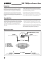
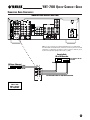
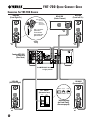
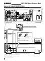
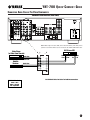
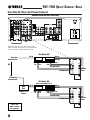
YHT-700
QUICK-CONNECT GUIDE
YHT-700 Q U I C K -C O N N E CT G U I D E
I NTRODUCTION
Yamaha developed the YHT-700 A/V Home Theater
package to turn your home into a theater. In addition to
enhancing the sound of a video source, like your TV,
DVD, or VCR, the YHT-700 also superbly reproduces
audio sources, such as a CD player or a cassette deck.
For the video portion, you will need a television or
monitor. Refer to the Yamaha HTR-5550 Ownerís Manual,
as well as those that came with your other components,
for complete instructions and cautions. Be sure to turn off
all power while making connections.
This Quick-Connect Guide will help you get started.
Study the speaker system plan (below), and then use
the interconnect diagrams (on the following pages) to
connect the receiver, DVD player and speakers to your
system.
Save this Quick-Connect Guide for future reference.
NOTE: Label the end of each speaker wire (i.e., left rear, right
front, etc.) before connecting them to the A/V receiver. For wire
runs over 30 feet, use larger 18- or 16-gauge speaker wire.
T OOLS A ND P ARTS
∑ Wire strippers (optional)
The YHT-700 Home Theater package consists of
(1) HTR-5550 A/V receiver with (1) universal remote
control, (1) DV-C6480 DVD Player, (4) 2-way NS-A480
front/rear speakers, (1) NS-AC480 2-way center-channel
speaker, 100' of speaker wire, (1) 0.5 m optical cable,
(1) 10' RCA audio cable, (1) YST-SW45 Powered
Subwoofer, and related owner's manuals. You will
also need:
∑ Velcro (for secure fastening of NS-AC480 on a TV)
∑ Brackets, toggle bolts, molly anchor screws, or sheet
metal screws (for securing NS-A480 speakers to walls)
NOTE: If you are unsure of how to securely and safely fasten
speakers to a wall, please contact a reliable source about the best
type of hardware for your particular wall's construction.
Secure installation is the purchaser's responsibility.
S PEAKER S YSTEM P LAN
YST-SW45 Subwoofer (on floor)
C
NS-A480
(left side, same height as TV)
L
NS-AC480
(on top or below TV)
NS-A480
Sub
(right side, same height as TV)
R
6'~ 8' apart
L = Left Channel
R = Right Channel
C = Center Channel
S = Surround Channel
Couch
Listening Area
NS-A480
(on stand or wall, at least
ear level or preferably higher)
2
S
8'~10' apart
S
NS-A480
(on stand or wall, at least
ear level or preferably higher)
YHT-700 Q U I C K -C O N N E C T GU I D E
C ONNECTING AUDIO C OMPONENTS
Yamaha HTR-5550 Receiver (Rear Panel)
NOTE: For your convenience, the Yamaha HTR-5550 receiver is equipped with
two switched AC outlets(100 W max.). If desired, use them to power on connected
components (e.g.,CD player) each time the receiver is turned on. However, do not
use them for components equipped with clocks (e.g.,VCR).
Cassette Deck,
CD or MD Recorder
* Use Playback Or Line Out
** Use Line In
CD Player (Changer)
R Out*
L Out
R Out
R
L
R
L
L Out*
R In** L In**
DVD
CD
IN
(PLAY)
MD
/CD-R
OUT
(REC)
Use RCA Audio Cables For Audio Interconnections
AUDIO
RCA Cable Color Codes
Yellow = Video
White = Left Audio
Red = Right Audio
3
YHT-700 Q U I C K -C O N N E C T GU I D E
C ONNECTING T HE YHT-700 S PEAKERS
NS-A480
(Front Right Ch.)
NS-A480
(Front Left Ch.)
NS-AC480
(Center Channel)
RED = positive (+)
use clear wire
BLK = negative (-)
use clear with
white stripe wire
Strip 1/ 4 " off ends of
speaker wires.
Stripe
Wire
Loosen terminals.
-
+
Insert speaker wires;
tighten terminals.
Stripe
Wire
-
+
Speaker
Wiring
-
Stripe
Wire
+
Yamaha HTR-5550
A/V Receiver
(Rear Panel)
Set IMPEDANCE Selector
to right position.
NS-A480
(Surround Left)
NS-A480
(Surround Right)
STANDBY/ON
HIGH CUT
VOLUME
YST-SW45
(Subwoofer Rear)
INPUT2
LOW
OFF
Stripe
Wire
4
+
50 Hz
150 Hz
0
10
AUTO
STANDBY
HIGH
Initial Settings
(on Front Panel
also see page 9)
Stripe
Wire
+
YHT-700 Q U I C K -C O N N E C T GU I D E
C ONNECTING V IDEO C ABLES FOR V IDEO C OMPONENTS
Yamaha HTR-5550 Receiver (Rear Panel)
NOTE: When using a hi-fi stereo VCR, set the Tuner/Line switch
(on the VCR) to Line position to record from another source
connected to the Yamaha HTR-5550 receiver.
Video Out
Satellite Receiver
(or Cable Box)
Video Out
Hi-Fi Stereo VCR
ANT Out
(RF Out)
Video In
Monitor/TV
Use RCA Video Cables And Jacks For Video Interconnections
Video In
Optional 75-ohm
Coaxial Cable
ANT In
RCA Cable Color Codes
Yellow = Video
White = Left Audio
Red = Right Audio
For S Video Connections, Please Refer To The HTR-5550 Owner's Manual
5
YHT-700 Q U I C K -C O N N E C T GU I D E
C ONNECTING T HE YAMAHA DV-C6480 DVD P LAYER
Yamaha HTR-5550 Receiver (Rear Panel)
DVD
R
L
V
Use the Included RCA Cables for Analog and Video
Connections Between the DVD Player and Receiver.
Analog Out*
Connecting Optical Cable
Optical Cable
(Included)
Remove dust cap.
Align plug with terminal
and insert cable.
NOTES:
∑ On both ends of the optical cable, align and firmly insert
each plug into its mating terminal.
∑ During connection, do not bend the optical cable.
∑ Keep dust caps and reattach them if terminals are not used.
RCA Cable Color Codes
MAIN
R
L
SURROUND
CENTER
SUB
WOOFER
NOTE: Use the optical connection to enjoy 5.1 - channel surround sound
found on DVDs recorded in the Dolby Digital or DTS Digital Surround format.
6CH
DISCRETE
L
1
PR
OUT
R
MIXED 2CH
AUDIO OUT
IN
2
Y
PB
COMPONENT VIDEO OUT
(480p/480i)
S VIDEO
VIDEO
VIDEO OUT
COAXIAL
OPTICAL
PCM/
DTS
DIGITAL
REMOTE
CONTROL
Yamaha DV-C6480 DVD Player (Rear Panel)
*Analog Audio Out connections are required for playback of CD-Rs and
recording from DVD to VCR.
Dolby Digital is a trademark of Dolby Laboratories Licensing Corporation.
DTS is a trademark of DTS Technology LLC.
6
Yellow = Video
White = Left Audio
Red = Right Audio
YHT-700 Q U I C K -C O N N E C T GU I D E
C ONNECTING AUDIO C ABLES F OR V IDEO C OMPONENTS
Yamaha HTR-5550 Receiver (Rear Panel)
NOTE: When using a hi-fi stereo VCR, set the Tuner/Line switch (on the VCR) to Line
position to record from another source connected to the Yamaha HTR-5550 receiver.
Video Player
(or Video Game Console)
Audio L Out
Audio R Out
Satellite
Receiver
Hi-Fi Stereo VCR
R
R
AUDIO
L
VIDEO
L
V
VIDEO
V-AUX
Audio
L Out
Audio
R Out
Audio
L In
Audio
R In
IN
VCR
Audio L Out
Audio R Out
OUT
D-TV
/CBL
DVD
MONITOR
OUT
VIDEO
RCA Cable Color Codes
Use RCA Audio Cables And Jacks For Audio Interconnections
Yellow = Video
White = Left Audio
Red = Right Audio
7
YHT-700 Q U I C K -C O N N E C T GU I D E
C ABLE H OOK -U P (B ASIC A ND P REMIUM C HANNELS )
Yamaha HTR-5550 Receiver (Rear Panel)
NOTE: When using a hi-fi stereo VCR, set the Tuner/Line
switch (on the VCR) to Line position to record from another
source connected to the Yamaha HTR-5550 receiver.
Hi-Fi Stereo VCR
ANT In
Basic Cable
(From Wall Jack)
Video In
Video Out
R
AUDIO
Audio
L In
OR
Audio
R In
Audio
R Out
VIDEO
L
L
R
Audio L Out
V
VIDEO
V-AUX
IN
RCA Audio Cables
VCR
OUT
RCA Audio Cables
RCA Video
Cables
D-TV
/CBL
DVD
MONITOR
OUT
Premium Cable
(From Wall Jack)
VIDEO
Hi-Fi Stereo VCR
Cable
Box
(Channel 3 or 4
Output)
ANT In
(Tuner set to Channel 3 or 4)
Video In
Video Out
R
R
Audio
L In
Audio
R In
Audio
R Out
Audio L Out
AUDIO
VIDEO
L
L
V
VIDEO
V-AUX
RCA Audio Cables
IN
VCR
OUT
RCA Audio Cables
RCA Video
Cables
D-TV
/CBL
DVD
RCA Cable Color Codes
Yellow = Video
White = Left Audio
Red = Right Audio
8
MONITOR
OUT
VIDEO
YHT-700 Q U I C K -C O N N E C T GU I D E
I NITIAL A DJUSTMENT O F T HE YST-SW45 S UBWOOFER
To achieve optimum volume balance between the
YST-SW45 Subwoofer and the NS-A480 Main Speakers,
perform the following procedure:
1. Insert the YST-SW45's power plug into an AC outlet.
2. On the YST-SW45's rear panel, slide the POWER
switch to ON.
3. On the YST-SW45's front panel, set the VOLUME
control to 0 (minimum setting), the HIGH CUT
control to its midpoint position, and press the
STANDBY/ON switch to ON. Then power on all
other components.
YST-SW45 Subwoofer
(Rear Panel)
OUTPUT
INPUT 2
TO SPEAKERS
4. Play an audio source and adjust the HTR-5550's
VOLUME control to a desired listening level.
5. On the YST-SW45's front panel, increase the
VOLUME control gradually to adjust the balance
the volume between the YST-SW45 Subwoofer and
the NS-A480 Main Speakers.
NOTE: Once the volume is balanced between the
subwoofer and the main speakers, you can adjust the
volume of your whole sound system by using the
HTR-5550's VOLUME control.
Initial Settings
(on Front Panel)
STANDBY/ON
AUTO
STANDBY
HIGH CUT
VOLUME
LOW HIGH
OFF
FROM AMPLIFIER
INPUT 1
50 Hz
150 Hz
0
10
POWER
ON
POWER
ON
OFF
OFF
To AC Outlet
9
YHT-700 Q U I C K -C O N N E C T GU I D E
P ROGRAMMING T HE U NIVERSAL R EMOTE C ONTROL
Turns On
Component's
Power
Component
Selector
Buttons
TRANSMIT
CODE SET
SYSTEM
STANDBY
POWER
MD/CD-R
TUNER
SLEEP
DVD
D-TV/CBL
V-AUX
6CH INPUT
VCR
A
B
AMP
POWER
POWER
TV
AV
CD
+
+
+
TV VOL
TV CH
VOLUME
-
-
-
TV MUTE
TV INPUT
Indicator LED
S ETTING U P C OMPONENTS
Perform the procedure for each component you own.
At the end of each step 5, the remote control's processor
will automatically assign the selected component's
control functions to its own buttons, ready for your use.
S ETTING U P Y OUR TV
1. Turn on the television set and look up a setup code
for your brand of television (codes are located at the
back of the HTR-5550 Owner's Manual).
2. On the remote control, press button B.
MUTE
Use Keypad
To Enter
Setup Codes
TRANSMIT
CODE SET
HALL
JAZZ CLUB
ROCK
CONCERT
1
2
3
4
TV
AV
TV
SPORTS
MONO
MOVIE
MOVIE
THEATER 1
MOVIE
THEATER 2
CD
5
6
7
8
SELECT
MA TRIX 6.1
STEREO
0
+10
ENTER
/DTS
SUR.
9
ENTERTAINMENT
POWER
POWER
EFFECT
LEVEL
PRESET/CH
SYSTEM
STANDBY
POWER
MD/CD-R
TUNER
SLEEP
DVD
D-TV/CBL
V-AUX
6CH INPUT
VCR
A
B
AMP
SET MENU
MENU
TITLE
A/B/C/D/E
-
SELECT
+
TEST
RETURN
DISPLAY
REC
Used to Change
and Implement
the Settings
AUDIO
3. Press CODE SET using a ballpoint pen or similar
object. The TRANSMIT indicator LED will flash
twice.
DISC SKIP
TRANSMIT
CODE SET
4. Using the keypad, enter the four-digit setup code.
The indicator LED will flash twice after your entry.
If the LED did not flash twice, repeat steps 3 and 4.
The YHT-700 Home Theater package includes a universal remote control. It comes pre-programmed with
factory codes to control your HTR-5550 receiver and
most Yamaha audio components. To program other
brands of components (i.e., TV, VCR, etc.) or if your
Yamaha unit does not respond, you will need to
program the remote control with the manufacturer's
codes (listed on the back pages of the HTR-5550
Owner's Manual).
NOTE: The universal remote control is designed to control
most major brands of audio and video components. For other
units, use the original remote control supplied with the product.
P OWER O N
1. Load the supplied batteries into the remote control.
2. Aim the remote control at the receiver, press the
SYSTEM POWER button.
3. The receiver should turn on.
10
HALL
JAZZ CLUB
ROCK
CONCERT
ENTERTAINMENT
1
2
3
4
TV
SPORTS
MONO
MOVIE
MOVIE
THEATER 1
MOVIE
THEATER 2
5
6
7
8
SELECT
MA TRIX 6.1
STEREO
0
+10
/DTS
SUR.
9
ENTER
EFFECT
NOTE: If you wait more than 30 seconds during step 4, the
process will be canceled. If this happens, start from Step 2.
5. To verify the code works, aim the remote control at
the television set, press the TV POWER button.
The television set should turn off. If it doesn't
respond, use another code for the same manufacturer and repeat steps 3 through 5.
CODE SET
TRANSMIT
POWER
POWER
TV
AV
STANDBY
SYSTEM
POWER
YHT-700 Q U I C K -C O N N E C T GU I D E
P ROGRAMMING THE UNIVERSAL R EMOTE C ONTROL (C ONTINUED )
S ETTING U P Y OUR C ABLE B OX ( OR DSS)
S ETTING U P O THER C OMPONENTS
2. On the remote control, press D-TV/CBL.
2. On the remote control, press the desired component
button (e.g., CD or MD/CD-R).
1. Turn on the cable box (or DSS) and look up a setup
code for your brand of cable box (or DSS) (codes are
located at the back of the HTR-5550 Owner's Manual).
1. Turn on the component (e.g., CD player, tape deck,
or MD player) and look up a setup code for your
brand of component.
TRANSMIT
CODE SET
SYSTEM
STANDBY
POWER
MD/CD-R
TUNER
SLEEP
DVD
D-TV/CBL
V-AUX
6CH INPUT
VCR
A
B
AMP
POWER
POWER
TV
AV
CD
3. Press CODE SET using a ballpoint pen or similar
object. The TRANSMIT indicator LED will flash
twice.
4. Using the keypad, enter the four-digit setup code.
The indicator LED will flash twice after your entry.
If the LED did not flash twice, repeat steps 3 and 4.
5. To verify the code works, aim the remote control at
the cable box (or DSS), press D-TV/CBL, and then
press AV POWER . The unit should turn off. If it
doesn'trespond, use another code for the same
manufacturer and repeat steps 3 through 5.
S ETTING U P Y OUR VCR
1. Turn on the VCR and look up a setup code for your
brand of VCR.
3. Press CODE SET using a ballpoint pen or similar
object. The TRANSMIT indicator LED will flash
twice.
4. Using the keypad, enter the four-digit setup code.
The indicator LED will flash twice after your entry.
If the LED did not flash twice, repeat steps 3 and 4.
5. To verify the code works, aim the remote control at the
component, press the appropriate component button,
and then press AV POWER. The unit should turn off.
If it doesn't respond, use another code for the same
manufacturer and repeat steps 3 through 5.
CODE SET
TRANSMIT
POWER
POWER
TV
AV
STANDBY
SYSTEM
POWER
NOTE: Your component's original remote control must have a
power On/Off function in order for this remote to control your
component's power function.
2. On the remote control, press VCR.
TRANSMIT
CODE SET
SYSTEM
STANDBY
POWER
MD/CD-R
TUNER
SLEEP
DVD
D-TV/CBL
V-AUX
6CH INPUT
VCR
A
B
AMP
POWER
POWER
TV
AV
CD
3. Press CODE SET using a ballpoint pen or similar
object. The TRANSMIT indicator LED will flash
twice.
4. Using the keypad, enter the four-digit setup code.
The indicator LED will flash twice after your entry.
If the LED did not flash twice, repeat steps 3 and 4.
5. To verify the code works, aim the remote control at
the VCR, press VCR, and then press AV POWER.
The VCR should turn off. If it doesn't respond, use
another code for the same manufacturer and repeat
steps 3 through 5.
11
YHT-700 Q U I C K -C O N N E C T GU I D E
O PERATING T HE UNIVERSAL R EMOTE C ONTROL
O VERVIEW
3. Load a DVD into the DVD player.
The universal remote control will control up to nine
different types of components each of which becomes
active when you press a selection ( except TV which
has priority and TV function buttons are always active).
We can only briefly describe some functions here, and
we encourage you use the HTR-5550 Owner's Manual
to gain additional experience with this powerful unit.
4. Aim the remote control at the DVD player, and press
(forward button) to start play.
P LAYING A V IDEOCASSETTE
You can reset the remote control to factory codes for
all components or a desired component, as follows:
1. Aim the remote control at the HTR-5550, press
SYSTEM POWER to turn the receiver on. Press
VCR as the input for the receiver.
NOTE: The DVD player's controls are now assigned to
the remote control buttons, since DVD was the last
selected component.
R ESETTING THE R EMOTE C ONTROL TO F ACTORY C ODES
R ESETTING C ODES F OR A LL C OMPONENTS
1. Press any component selector.
2. Aim the remote control at the TV, press the TV
POWER to turn the television on.
2. Press CODE SET using a ballpoint pen or similar
object. The TRANSMIT indicator LED will flash twice.
3. Aim the remote control at the VCR, press VCR to
select the component, and then press AV POWER
to turn the VCR on. Put a tape in the VCR, press
(forward button) to start play.
3. Using the keypad, enter the code "9990".
NOTE: At this point, the VCR controls are assigned to
the remote control, since VCR was the last selected
component.
4. The indicator LED will flash twice to confirm all
codes have been reset to factory values. If the LED
does not flash twice, repeat steps 1 through 3.
R ESETTING C ODES F OR A D ESIRED C OMPONENT
1. Press a component selector button that matches the
component you wish to reset to factory codes.
2. Press CODE SET. The TRANSMIT indicator LED
will flash twice.
3. Using the keypad, enter the code "0000".
P LAYING A DVD
1. Aim the remote control at the HTR-5550, press
SYSTEM POWER to turn the receiver on.
Press DVD as the input for the receiver.
2. Press DVD and then press AV POWER to turn the
DVD player on.
NOTE: If the DVD player is plugged into the switched
outlet (on the back of the receiver) and its power switch AC
was already engaged, the unit will come on each time the
receiver is powered on.
4. The indicator LED will flash twice to confirm all
codes have been reset to factory values. If the LED
does not flash twice, repeat steps 1 through 3.
5. For your convenience, the following reference chart
lists the factory codes:
Component
Selector Button
Component
Code
CD
MD/CD-R
TUNER
DVD
CD
MD
TUNER
DVD
0005
0024
0003
0098
©2002 YAMAHA ELECTRONICS CORPORATION, USA
6660 Orangethorpe Avenue, Buena Park, CA 90620
PH: (714) 522-9105; FAX: (888) 435-7922
http://www.yamaha.com
12
Yamaha
Yamaha
Yamaha
Yamaha