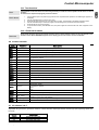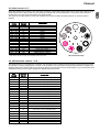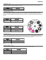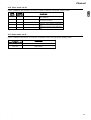
1
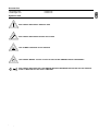
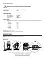
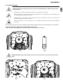
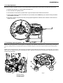
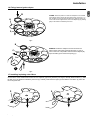
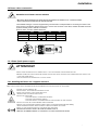
Read the instructions in this handbook carefully, as they give important information regarding safety during installation, use and
maintenance.
Be sure to keep this instruction manual with the fixture, in order to consult it in the future. If the fixture is sold or given to another
operator, make certain he or she also receives the manual, to be able to read about its operation and follow the relative
instructions.
•
•
•
•
•
•
•
•
•
•
•
•
•
•
•
•
THIS UNIT IS NOT FOR HOME USE, ONLY PROFESSIONAL APPLICATIONS
AFTER HAVING REMOVED THE PACKAGING, CHECK THAT THE FIXTURE IS NOT DAMAGED IN ANY WAY. IF IN DOUBT, DON'T USE IT
AND CONTACT AN AUTHORIZED SGM TECHNICAL SERVICE CENTRE.
PACKAGING MATERIAL (PLASTIC BAGS, POLYSTYRENE FOAM, NAILS, ETC.) MUST NOT BE LEFT WITHIN CHILDREN'S REACH, AS IT
CAN BE DANGEROUS.
THIS FIXTURE MUST ONLY BE OPERATED BY ADULTS. DO NOT ALLOW CHILDREN TO TAMPER OR PLAY WITH IT.
ELECTRICAL WORK NECESSARY FOR INSTALLING THE FIXTURE MUST BE CARRIED OUT BY A QUALIFIED ELECTRICIAN OR
EXPERIENCED PERSON.
NEVER USE THE FIXTURE UNDER THE FOLLOWING CONDITIONS:
- IN PLACES SUBJECT TO EXCESSIVE HUMIDITY
- IN PLACES SUBJECT TO VIBRATIONS OR BUMPS.
- IN PLACES WITH A TEMPERATURE OF OVER 45°C OR LESS THAN 2°C
PROTECT THE FIXTURE FROM EXCESSIVE DRYNESS OR HUMIDITY (IDEAL CONDITIONS ARE BETWEEN 35% AND
80%).
DO NOT DISMANTLE OR MODIFY THE FIXTURE.
MAKE CERTAIN THAT NO INFLAMMABLE LIQUIDS, WATER OR METAL OBJECTS ENTER THE FIXTURE.
THE MINIMUM DISTANCE BETWEEN THE FIXTURE AND THE SURFACE TO BE LIT MUST BE NO LESS THAN 1.5 METRES
SHOULD ANY LIQUID BE SPILLED ON THE FIXTURE, DISCONNECTED THE POWER SUPPLY TO THE FIXTURE IMMEDIATELY.
IN THE EVENT OF SERIOUS OPERATING PROBLEMS, STOP USING THE FIXTURE IMMEDIATELY AND EITHER CONTACT THE NEAREST
SGM SALES POINT FOR A CHECK OR CONTACT THE MANUFACTURER DIRECTLY.
DO NOT OPEN THE FIXTURE - THERE ARE NO USER SERVICEABLE PARTS INSIDE.
NEVER TRY TO REPAIR THE FIXTURE YOURSELF. REPAIRS BY UNQUALIFIED PEOPLE COULD CAUSE DAMAGE OR FAULTY
OPERATION. CONTACT YOUR NEAREST AUTHORIZED SERVICE CENTRE.
WHEN CARRYING OUT ANY WORK, ALWAYS COMPLY SCRUPULOUSLY WITH ALL THE NORMS (PARTICULARLY REGARDING SAFETY)
CURRENTLY IN FORCE IN THE COUNTRY IN WHICH THE FIXTURE'S BEING USED.
Do not place the unit on inflammable parts or material
Always insist on original spare parts being fitted.
General warranty conditions
•
•
•
•
•
THE UNIT IS GUARANTEED FOR 12 MONTHS FROM THE DATE OF PURCHASE AGAINST MANUFACTURING MATERIAL DEFECTS.
BREAKDOWN CAUSED BY CARELESSNESS AND IMPROPER USE OF THE FIXTURE IS EXCLUDED.
THE GUARANTEE IS NO LONGER VALID IF THE UNIT HAS BEEN TAMPERED WITH OR REPAIRED BY UNAUTHORIZED PERSONNEL.
REPLACEMENT OF THE FIXTURE IS NOT FORESEEN BY THE GUARANTEE.
EXTERNAL PARTS, KNOBS, SWITCHES, REMOVABLE PARTS AND LAMPS ARE EXCLUDED FROM THE GUARANTEE: THESE ARE COVERED BY THEIR
MANUFACTURERS' GUARANTEE CONDITIONS.
TRANSPORT COSTS AND RELATED RISKS ARE BORNE BY THE FIXTURE'S OWNER.
THE GUARANTEE IS VALID TO ALL EFFECTS ONLY ON PRESENTATION OF THE GUARANTEE CERTIFICATE TO THE MANUFACTURER OR THE NEAREST
SGM TECHNICAL ASSISTANCE CENTRE.
ALWAYS QUOTE THE UNIT'S SERIAL NUMBER AND MODEL WHEN CONTACTING YOUR RESELLER FOR INFORMATION OR ASSISTANCE.
Protect the environment: don't throw packing material into your
garbage can return it to your SGM retailer or take it to the nearest
special waste collection point.
GiottoSpot 400 rel.1.01
1
GB
General instructions
index
GENERAL WARNINGS AND INSTRUCTIONS . . . . . . . . . . . . . . . . . . . . . . . . . . . . . . . . . . . . . . . . . . . . . . . . . . . . . .1
GUARANTEE CONDITIONS . . . . . . . . . . . . . . . . . . . . . . . . . . . . . . . . . . . . . . . . . . . . . . . . . . . . . . . . . . . . . . . . . .1
PRESENTATION . . . . . . . . . . . . . . . . . . . . . . . . . . . . . . . . . . . . . . . . . . . . . . . . . . . . . . . . . . . . . . . . . . . . . . . .3
MAIN FEATURES . . . . . . . . . . . . . . . . . . . . . . . . . . . . . . . . . . . . . . . . . . . . . . . . . . . . . . . . . . . . . . . . . . . . . . . .4
. . . . . . . . . . . . . . . . . . . . . . . . . . . . . . . . . . . . . . . . . . . . . . . . . . . . . . . . . . . . . . . . . . . . . . . .5
ACCESSORIES
SYMBOLS USED . . . . . . . . . . . . . . . . . . . . . . . . . . . . . . . . . . . . . . . . . . . . . . . . . . . . . . . . . . . . . . . . . . . . . . . .5
ELECTRICAL SPECIFICATIONS . . . . . . . . . . . . . . . . . . . . . . . . . . . . . . . . . . . . . . . . . . . . . . . . . . . . . . . . . . . . . . . .6
MECHANICAL FEATURES . . . . . . . . . . . . . . . . . . . . . . . . . . . . . . . . . . . . . . . . . . . . . . . . . . . . . . . . . . . . . . . . . . .6
1 INSTALLATION . . . . . . . . . . . . . . . . . . . . . . . . . . . . . . . . . . . . . . . . . . . . . . . . . . . . . . . . . . . . . . . . . . . . . . . .7
1.2 ACCESS TO INTERNAL COMPONENTS . . . . . . . . . . . . . . . . . . . . . . . . . . . . . . . . . . . . . . . . . . . . . . . . . .8
1.3 INSTALLING THE LAMP . . . . . . . . . . . . . . . . . . . . . . . . . . . . . . . . . . . . . . . . . . . . . . . . . . . . . . . . . . . .9
1.4 LAMP ALIGNMENT . . . . . . . . . . . . . . . . . . . . . . . . . . . . . . . . . . . . . . . . . . . . . . . . . . . . . . . . . . . . . . .9
1.5 INSTALLING /REPLACING GOBOS . . . . . . . . . . . . . . . . . . . . . . . . . . . . . . . . . . . . . . . . . . . . . . . . . . . .10
1.6 FITTING/REMOVAL GOBO ADAPTER . . . . . . . . . . . . . . . . . . . . . . . . . . . . . . . . . . . . . . . . . . . . . . . . . . .10
1.7 INSTALLING /REPLACING COLOR FILTERS . . . . . . . . . . . . . . . . . . . . . . . . . . . . . . . . . . . . . . . . . . . . . .12
1.8 CONSTRUCTING A POWER CORD . . . . . . . . . . . . . . . . . . . . . . . . . . . . . . . . . . . . . . . . . . . . . . . . . . . .12
1.9 GIOTTO SPOT'S POWER SUPPLY . . . . . . . . . . . . . . . . . . . . . . . . . . . . . . . . . . . . . . . . . . . . . . . . . . .12
1.91 MOUNTING THE FIXTURE ON TRUSSING OR SIMILAR STRUCTURES . . . . . . . . . . . . . . . . . . . . . . . . . . . . .12
1.92 POSITIONING THE FIXTURE . . . . . . . . . . . . . . . . . . . . . . . . . . . . . . . . . . . . . . . . . . . . . . . .13
1.93 INSTALLING THE CLAMPS . . . . . . . . . . . . . . . . . . . . . . . . . . . . . . . . . . . . . . . . . . . . . . . . .13
2 SIGNAL CABLE . . . . . . . . . . . . . . . . . . . . . . . . . . . . . . . . . . . . . . . . . . . . . . . . . . . . . . . . . . . . . . . . . . . . . .14
2.1 DMX TERMINATION PLUG CONSTRUCTION . . . . . . . . . . . . . . . . . . . . . . . . . . . . . . . . . . . . . . . . . . . . .14
2.2 RS-232 CONNECTION . . . . . . . . . . . . . . . . . . . . . . . . . . . . . . . . . . . . . . . . . . . . . . . . . . . . . . . . . .15
3 "CONTROL" MICROCOMPUTER . . . . . . . . . . . . . . . . . . . . . . . . . . . . . . . . . . . . . . . . . . . . . . . . . . . . . . . . . . .16
3.1 MENU NAVIGATION . . . . . . . . . . . . . . . . . . . . . . . . . . . . . . . . . . . . . . . . . . . . . . . . . . . . . . . . . . . . .16
3.2 ALLOCATING THE START CHANNEL (ADDRESSING) . . . . . . . . . . . . . . . . . . . . . . . . . . . . . . . . . . . . . . . .18
3.3 PAN DIRECTION . . . . . . . . . . . . . . . . . . . . . . . . . . . . . . . . . . . . . . . . . . . . . . . . . . . . . . . . . . . . . . .18
3.31 LIMITING PAN . . . . . . . . . . . . . . . . . . . . . . . . . . . . . . . . . . . . . . . . . . . . . . . . . . . . . . . . .18
3.4 TILT DIRECTION . . . . . . . . . . . . . . . . . . . . . . . . . . . . . . . . . . . . . . . . . . . . . . . . . . . . . . . . . . . . . . . .19
3.41 LIMITING TILT . . . . . . . . . . . . . . . . . . . . . . . . . . . . . . . . . . . . . . . . . . . . . . . . . . . . . . . . .19
3.5 INVERTING PAN/TILT . . . . . . . . . . . . . . . . . . . . . . . . . . . . . . . . . . . . . . . . . . . . . . . . . . . . . . . . . . . .19
3.6 LAMP ELAPSED TIME COUNTER . . . . . . . . . . . . . . . . . . . . . . . . . . . . . . . . . . . . . . . . . . . . . . . . . . . . .19
3.61 RESETTING THE LAMP ELAPSED TIME COUNTER . . . . . . . . . . . . . . . . . . . . . . . . . . . . . . . . . .19
3.7 LAMP STRIKE (IGNITION) COUNTER . . . . . . . . . . . . . . . . . . . . . . . . . . . . . . . . . . . . . . . . . . . . . . . . . .20
3.71 RESETTING THE LAMP STRIKE COUNTER . . . . . . . . . . . . . . . . . . . . . . . . . . . . . . . . . . . . . . .20
3.8 FIXTURE OPERATING TIME COUNTER . . . . . . . . . . . . . . . . . . . . . . . . . . . . . . . . . . . . . . . . . . . . . . . . .20
3.9 INPUT SIGNAL . . . . . . . . . . . . . . . . . . . . . . . . . . . . . . . . . . . . . . . . . . . . . . . . . . . . . . . . . . . . . . . . .20
3.10 PAN/TILT MOVEMENT RESOLUTION . . . . . . . . . . . . . . . . . . . . . . . . . . . . . . . . . . . . . . . . . . . . . . . . .20
3.11 REMOTE CONTROLLED LAMP STRIKE (IGNITION) . . . . . . . . . . . . . . . . . . . . . . . . . . . . . . . . . . . . . . . .20
3.12 REMOTE CONTROLLED FIXTURE RESET . . . . . . . . . . . . . . . . . . . . . . . . . . . . . . . . . . . . . . . . . . . . . .21
3.13 CONTROLLING ACCELERATION AND SPEED . . . . . . . . . . . . . . . . . . . . . . . . . . . . . . . . . . . . . . . . . . . .21
3.14 DISPLAY BRIGHTNESS . . . . . . . . . . . . . . . . . . . . . . . . . . . . . . . . . . . . . . . . . . . . . . . . . . . . . . . . . .21
3.15 DISPLAY VIEWING POSITION . . . . . . . . . . . . . . . . . . . . . . . . . . . . . . . . . . . . . . . . . . . . . . . . . . . . . .21
3.16 DMXDLY . . . . . . . . . . . . . . . . . . . . . . . . . . . . . . . . . . . . . . . . . . . . . . . . . . . . . . . . . . . . . . . . . . . .21
3.17 LOCKING/UNLOCKING THE SHUTTER . . . . . . . . . . . . . . . . . . . . . . . . . . . . . . . . . . . . . . . . . . . . . . . . .22
3.18 SETTING DEFAULT PARAMETERS . . . . . . . . . . . . . . . . . . . . . . . . . . . . . . . . . . . . . . . . . . . . . . . . . . .22
3.19 RESTORING DEFAULT PARAMETERS . . . . . . . . . . . . . . . . . . . . . . . . . . . . . . . . . . . . . . . . . . . . . . . . .22
3.20 SETTING THE STARTING POSITION OF THE ROTATING GOBOS AND THE GOBO, COLORS, EFFECTS WHEELS .22
3.21 TEST FUNCTIONS . . . . . . . . . . . . . . . . . . . . . . . . . . . . . . . . . . . . . . . . . . . . . . . . . . . . . . . . . . . . .23
3.22 RESERVED FUNCTIONS . . . . . . . . . . . . . . . . . . . . . . . . . . . . . . . . . . . . . . . . . . . . . . . . . . . . . . . . .23
4 GIOTTO SPOT 400'S CONTROL CHANNELS . . . . . . . . . . . . . . . . . . . . . . . . . . . . . . . . . . . . . . . . . . . . . . . . . . .23
4.1 IRIS CHANNEL -CH 5- . . . . . . . . . . . . . . . . . . . . . . . . . . . . . . . . . . . . . . . . . . . . . . . . . . . . . . . . . . . .23
4.2 COLOR CHANNEL -CH 6- . . . . . . . . . . . . . . . . . . . . . . . . . . . . . . . . . . . . . . . . . . . . . . . . . . . . . . . . .24
4.3 GOBO CHANNEL -CH 7- . . . . . . . . . . . . . . . . . . . . . . . . . . . . . . . . . . . . . . . . . . . . . . . . . . . . . . . . . .25
4.4 SHUTTER/STROBE CHANNEL - CH 8- . . . . . . . . . . . . . . . . . . . . . . . . . . . . . . . . . . . . . . . . . . . . . . . . .26
4.5 DIMMER -CH 9- . . . . . . . . . . . . . . . . . . . . . . . . . . . . . . . . . . . . . . . . . . . . . . . . . . . . . . . . . . . . . . .26
4.6 GOBO ROTATION -CH 10- . . . . . . . . . . . . . . . . . . . . . . . . . . . . . . . . . . . . . . . . . . . . . . . . . . . . . . . . .26
4.7 PRISMS -CH 11- . . . . . . . . . . . . . . . . . . . . . . . . . . . . . . . . . . . . . . . . . . . . . . . . . . . . . . . . . . . . . . .26
4.8 PRISM ROTATION - CH 12- . . . . . . . . . . . . . . . . . . . . . . . . . . . . . . . . . . . . . . . . . . . . . . . . . . . . . . . .26
4.9 ELECTRONIC FOCUS -CH 13- . . . . . . . . . . . . . . . . . . . . . . . . . . . . . . . . . . . . . . . . . . . . . . . . . . . . . .27
4.10 ZOOM- CH 14 - . . . . . . . . . . . . . . . . . . . . . . . . . . . . . . . . . . . . . . . . . . . . . . . . . . . . . . . . . . . . . . .27
4.11 EFFECTS WHEEL -CH 15- . . . . . . . . . . . . . . . . . . . . . . . . . . . . . . . . . . . . . . . . . . . . . . . . . . . . . . . .27
4.12 FROST - CH 16 - . . . . . . . . . . . . . . . . . . . . . . . . . . . . . . . . . . . . . . . . . . . . . . . . . . . . . . . . . . . . . .28
4.13 MSPEED - CH 17 - . . . . . . . . . . . . . . . . . . . . . . . . . . . . . . . . . . . . . . . . . . . . . . . . . . . . . . . . . . . .28
4.14 REMOTE LAMP STRIKING AND RESET -CH 18- . . . . . . . . . . . . . . . . . . . . . . . . . . . . . . . . . . . . . . . . . .28
4.15 GOBOSHAKE - CH 19 - . . . . . . . . . . . . . . . . . . . . . . . . . . . . . . . . . . . . . . . . . . . . . . . . . . . . . . . . .28
4.16 COLOR MODE -CH 20- . . . . . . . . . . . . . . . . . . . . . . . . . . . . . . . . . . . . . . . . . . . . . . . . . . . . . . . . .29
4.17 GOBO MODE -CH 21- . . . . . . . . . . . . . . . . . . . . . . . . . . . . . . . . . . . . . . . . . . . . . . . . . . . . . . . . . .29
4.18 MACROS -CH 22- . . . . . . . . . . . . . . . . . . . . . . . . . . . . . . . . . . . . . . . . . . . . . . . . . . . . . . . . . . . . .29
CONVERSION TABLES . . . . . . . . . . . . . . . . . . . . . . . . . . . . . . . . . . . . . . . . . . . . . . . . . . . . . . . . . . . . . . . . . . . .29
2
GiottoSpot 400 rel.1.01
Giotto Spot is SGM's innovative professional moving head spot, specifically manufactured for use in high profile shows, theatres,
Television studios and entertainment venues in general.
Thanks to its cutting edge performance, the result of SGM's lengthy experience in mechanical and electronic design, Giotto Spot
is one of the world's best.
Its use of an MSR 400HR discharge lamp and a perfect optical system makes it one of the best fixtures currently on the market.
Made in Italy by SGM Electronic
Printed in September 2001 Rel.1.01
GiottoSpot 400 rel.1.01
3
GB
Presentation
Main features
Lamp
Giotto Spots use a Philips MSD 400HR (6000°K) discharge lamp.
Effects
-
Linear zoom (9° - 24°)
Fast linear iris
Automatic electronic focus
Linear dimmer ( 0-100% )
Shutter / strobe 12 fps with music sync
Colour wheel with 8 positions + white, supplied as standard with 8 dichroic colours
Effects wheel with 8 positions + white, fitted with 2 conv. filters, UV filter, 2 fixed gobos, 2 glass (texture) gobos, amber filter.
Colours can be fitted on the effects wheel, obtaining a total of 16 distinct colours.
Gobos can be fitted on the effects wheel and colour wheel using adapters.
Variable speed gobo scrolling
Gobo shake
Rainbow effect on gobo wheel.
Color change and gobo change with blackout
Color change and gobo change with music sync
2-tone beam, analog color selection, 16-speed rainbow
14-facet rotating prism with adjustable speed in both directions
5-facet rotating ½ prism (COMETA) with adjustable speed in both directions
Linear variable frost filter: from soft-edge to full-wash
Wood filter, CTO filter
Automatic re-positioning with black-out
Macros
Movement
- 540° Pan (2.8sec.) and 270° Tilt (1.7sec.)
- 8/16 bit movement resolution
- Automatic re-positioning in the event of accidental head movement
- Possibility of inverting Pan and Tilt movement
- Possibility of limiting Pan and Tilt range
- Variable acceleration and speed parameters
Electronic Ballast
Supplied as standard with every fixture
- Automatic universal power supply acceptance: 90-245V 50,60Hz
- Flicker-free
- Lamp power reduction in the event of fixture overheating
- Power Factor Correction
- Automatic energy saving in the event of beam black-out
- Hot re-strike.
Optics
- High luminous efficiency Optics
- Linear beam projection angle variation (9° - 24°)
- Autofocus
Display/Microcomputer
- The fixture can be "customized" according to type of installation: function tests available for each effect; Lamp On/Off via DMX
can be enabled; Fixture reset via DMX can be enabled; fixture addressing; display "flip" function (rotates through 180°);
adjustable display brightness and more.
- Info displayed includes: lamp elapsed time and strike counters, fixture operating time counter, software version supported.
Control signal
Input signal DMX 512 - RS 232
Mounting System
- "Fast-Lock" clamps supplied as standard with fixture
- Several clamp mounting points to enable the fixture to be mounted on any type of truss
- Safety chain/cable mounting points
4
GiottoSpot 400 rel.1.01
Accessories
cod:0061745
cod:0061746
GB
- Single flight case
- Double flight case
Symbols used
THIS SYMBOL INDICATES A GENERAL RISK
THIS SYMBOL INDICATES ELECTRIC SHOCK RISK
THIS SYMBOL INDICATES A HOT SURFACE
THIS SYMBOL MEANS “DO NOT PLACE THE UNIT ON INFLAMMABLE PARTS OR MATERIAL”
THIS SYMBOL INDICATES THAT THE MINIMUM DISTANCE BETWEEN THE FIXTURE AND THE SURFACE
TO BE LIT MUST BE NO LESS THAN 1.5 METRES
GiottoSpot 400 rel.1.01
5
ELECTRICAL SPECIFICATIONS
DANGER!! CLASS 1 FIXTURE.THIS UNIT MUST BE GROUNDED
POWER REQUIREMENTS:
UNIVERSAL 90V-245 V 50HZ,60HZ.
POWER ABSORBED:
520W
FUSED
2PZ - 8A CT
LAMP SPECIFICATIONS
LAMP:
LUMINOUS EFFICACY
COLOR COORDINATES
COLOR TEMPERATURE
LUMINOUS FLUX:
AVERAGE LIFE (50%)
CAP/BASE
OPTICAL SYSTEM:
MSR 400HR
80 LM/W
X,Y 328,323
6000°K
32000 LUMENS
750 HR.
GZZ9,5
INTERNAL OPTICAL GROUP COMPRISING HIGH LUMINOUS EFFICIENCY DICHROIC REFLECTOR; LINEAR BEAM ANGLE ADJUSTMENT
(9° -
24°) ELECTRONIC FOCUS.
METAL GOBO
DIAMETER:
IMAGE AREA:
30MM
24MM
DICHROIC GOBO
DIAMETER:
IMAGE AREA:
THICKNESS
28MM
24MM
1,1MM
COLOR FILTER
DIAMETER:
THICKNESS:
34MM
1,1MM
SETTING: VIA BUILT-IN MICRO-COMPUTER
CONTROL SIGNAL: USITT DMX 512 OR RS-232 DMX CONTROL
CHANNELS REQUIRED: 22
Mechanical Features
BODY: STRUCTURE IN CAST ALUMINIUM, CASING IN MOULDED TERMOPLAST
WEIGHT: 24.8 KG.
DIMENSIONS (MM.)
SGM Elettronica reserves the right to improve or modify its products at any time.
Always refer to the manual supplied with the unit to
avoid any risk of mistakes or operation which
does not correspond to manual indications.
6
GiottoSpot 400 rel.1.01
Installation
SGM has an on-going product development policy, so the information printed in this manual may not be completely up to date.
If any doubts arise regarding the topics covered in this manual or should any further help be required, our online services (internet-server
www.sgm.it ) are available 24 hours a day. In the FAQ section of the technical assistance zona, answers can be found to numerous common
queries: fixtures, firmware and manuals can also be downloaded whenever required.
Items supplied
Before proceeding with fixture installation, make certain that the packing contains all the items shown in the following list and
ensure that the fixture is undamaged.
If in doubt, don't use the fixture and contact an authorized SGM technical assistance centre and the freight company.
In fact, only the recipient can claim for any damage caused to the fixture during transport.
• GIOTTO SPOT 400
• WARRANTY
• INSTRUCTION MANUAL
• 1 MALE XLR 5 P CONNECTOR
• 1 FEMALE XLR 5 P CONNECTOR
• 1 POWER-CON CONNECTOR
• 2 FAST-LOCK CLAMPS
KEEP THE PACKING MATERIAL.
PACKING MATERIAL (PLASTIC BAGS, POLYSTYRENE FOAM, NAILS, ETC.) IS POTENTIALLY HAZARDOUS, SO MUST NEVER BE LEFT WITHIN CHILDREN'S
REACH. USE THE ORIGINAL PACKING IN THE EVENT OF HAVING TO RETURN THE FIXTURE TO THE MANUFACTURER FOR REPAIR OR MAINTENANCE: IT'S
BEEN DESIGNED SPECIFICALLY TO PROTECT THE FIXTURE DURING TRANSPORT.
GiottoSpot 400 rel.1.01
7
GB
Changes to this manual
Installation
1.2 Access to internal components
Giotto fixtures have a simple head opening mechanism.
All work must ALWAYS be carried out by qualified technical personnel.
ATTENTION: make certain that the fixture is switched off and that there is no risk of burns due to high component
temperature (wait at least 30 minutes after switching off)
To access internal components, proceed as follows:
1. Loosen the two screws shown in Fig.1 on both sides of the fixture
2. Remove the cover (1) in the direction indicated by the arrow (Fig. 2)
1
Fig. 1
Fig. 2
3. Unscrew the two threaded pins (5)(6) as shown in Fig.3
4. Swivel the whole block downwards (Fig. 4)
5
6
Fig. 3
8
Fig. 4
GiottoSpot 400 rel.1.01
Installation
ATTENTION! This fixture is designed exclusively for use with Philips MSD 400HR lamps. NEVER USE ANY OTHER
TYPES OF LAMPS.
•
•
DISCONNECT THE POWER SUPPLY BEFORE CARRYING OUT ANY WORK ON THE FIXTURE.
MAKE
CERTAIN THAT THE FIXTURE IS OFF AND THE TEMPERATURE OF THE COMPONENTS CAN'T CAUSE BURNS (WAIT
AT LEAST
•
NEVER
30 MINUTES AFTER SWITCHING OFF).
CARRY OUT ANY WORK IF THE FIXTURE DOESN'T HAVE ITS PROTECTIVE COVERS OR ITS LENSES ARE
DAMAGED. DISCHARGE LAMPS CAN EXPLODE.
•
NEVER
LOOK DIRECTLY AT THE LAMP WHEN IT'S LIT
-
DISCHARGE LAMPS EMIT
UV
RAYS WHICH ARE DANGEROUS
FOR SIGHT.
Inside the fixture's moving head, there is an optical system. Follow the following instructions when installing a lamp or relamping.
1. Disconnect the power supply, put on protective gloves and eyewear.
2. Open the fixture (see paragraph 1.2) and fit the lamp as shown in figures 4, 5, 6 and 7
Fig. 4
Fig. 5
ATTENTION!! When fitting a lamp, always use gloves or soft lint-free cloth - never touch it with your bare
hands.
Fig. 6
GiottoSpot 400 rel.1.01
Fig. 7
9
GB
1.3 Installing the lamp
Installation
1.4 Lamp alignment
Every time a new lamp is installed in the fixture, it must be aligned with the optical system to ensure optimum even light output from the unit.
1. Install the new lamp (par. 1.3), close the fixture and switch it on
2. Connect the fixture to a lighting console.
3. Point the fixture at a flat surface (if possible white or light colored) at least three metres from the fixture.
4. Set the control channels to obtain a white beam. Then open the IRIS, set the DIMMER fully open, FOCUS correctly and do NOT
project GOBOS or COLORS.
6. Use screws 1, 2 and-3 to align the lamp until an evenly projected light beam is obtained, with no shadows or zones which are
brighter than others.
1
J
LAM
P
A
M
P
A
D
2
L
J
LA M
ADJ
P
AD
3
1.5 Installing /replacing gobos
Metal: After opening the fixture, locate the gobo to be replaced, press delicately downwards (Fig.1) until the spring and the gobo
come out, making sure they don't fall inside the fixture. Install the new gobo (1) as shown (Fig.2), followed by the locking spring
(2).
Dichro: After opening the fixture, locate the gobo to be replaced, press delicately downwards (Fig.1) until the spring, ring and the
gobo come out, making sure they don't fall inside the fixture. Install the new gobo (3) as shown (Fig.2), followed by the ring (4)
and the locking spring (5).
3
5
Fig.1
1
4
2
Fig 2
A: Color wheel
B: Effects wheel
C: Gobo wheel
10
GiottoSpot 400 rel.1.01
Installation
B
FITTING: Select the position in which the adapter is to be installed
on the effects wheel, remove the colour filter if there is one (par. 1.7),
open the disks (3) using the least possible force, slide the spring (A)
in until it fits into the engraved slot, then fit the adapter (B) by pushing
lightly in the direction indicated by the arrow.
A
3
fig. 3
B
REMOVAL: Select the adapter to be removed from the
effects wheel, push lightly upwards (see figure 4 point 1)
until it comes out of its position and remove the adapter (B).
Open the disks (3) and remove the spring (C).
C
3
1
fig. 4
1.7 Installing /replacing color filters
Choose which of the wheel's dichroic filters is to be replaced, grip it firmly between your fingers, carefully widen the discs (1), slide
the filter out in the direction indicated by the arrow (2). Carefully widen the discs again (3) and slide the new filter in (4) until it fits
into its engraved slot.
4
2
1
GiottoSpot 400 rel.1.01
3
11
GB
1.6 Fitting/removal gobo adapter
Installation
1.8 Power cable construction
DANGER! ELECTRICAL SHOCK HAZARD
• ELECTRICAL WORK NECESSARY FOR INSTALLING THE FIXTURE MUST BE CARRIED OUT BY A QUALIFIED PERSON.
• CLASS 1 DEVICE, THE FIXTURE MUST BE SUITABLY EARTHED.
The POWER-CON type connector supplied along with the Giotto is indispensable for connecting the fixture to the
power supply. The following design shows how to connect the connector to the cable, whereas the table shows the
symbols normally used to indicate connections.
When in doubt, consult a qualified electrician.
CABLES
Brown
Blue
Yellow/Green
PIN
Phase
Neutral
Ground
TYPICAL
“L”
“N”
US
Yellow/Copper
Silver
Green
UK
Red
Black
Green
N
L
1.9 - Giotto Spot's power supply
ATTENTION!!
• DON'T POWER THE GIOTTO WITH A DIMMER CIRCUIT - THIS COULD DAMAGE THE ELECTRONIC BALLAST.
• BEFORE CONNECTING THE FIXTURE, MAKE CERTAIN THAT THE DATA ON THE FIXTURE'S PLATE CORRESPOND WITH THOSE OF THE
LOCAL MAIN POWER SUPPLY.
• THE FIXTURE MUST BE CONNECTED TO A CUT-OFF CIRCUIT.
1.91- Installing the fixture on a support structure
READ THE FOLLOWING SAFETY INFORMATION BEFORE PROCEEDING WITH THE INSTALLATION OF THE FIXTURE:
• FIXTURE NOT FOR DOMESTIC USE.
• DO NOT INSTALL THE FIXTURE NEAR SOURCES OF HEAT.
• INSTALL THE FIXTURE IN A WELL VENTILATED PLACE.
• AVOID BLOCKING AIR INTAKES AND OUTPUTS.
• DO NOT USE THE FIXTURE:
- IN PLACES SUBJECT TO VIBRATIONS OR BUMPS
- IN PLACES WITH EXCESSIVE HUMIDITY
- IN PLACES SUBJECT TO TEMPERATURES OF MORE THAN 45° OR LESS THAN 2°C
• DO NOT PLACE THE UNIT ON INFLAMMABLE PARTS OR MATERIAL
• PROTECT THE FIXTURE FROM EXCESSIVE HUMIDITY (IDEAL VALUES ARE BETWEEN 35 AND L’80%).
• AVOID INFLAMMABLE LIQUIDS, WATER OR METALLIC OBJECTS ENTERING THE FIXTURE .
• DON'T LIFT THE FIXTURE HOLDING IT BY THE MOVING PART (THE HEAD).
• POSITION THE FIXTURE AT LEAST 1.5M. FROM THE SURFACE TO BE LIT.
• KEEP ANY INFLAMMABLE MATERIAL AT A DISTANCE OF AT LEAST 1.5M FROM THE FIXTURE.
12
GiottoSpot 400 rel.1.01
Installation
1.92 Positioning the fixture
GB
Can be installed in any position.
OK
OK
OK
1.93 Fitting clamps
•Always use two clamps to hang the fixture.
•Fix the fixture to the support structure using safety chains fitted to the 2 holes on the underside of the fixture's base (Fig.2).
•Don't fix the safety chain to the handles.
6m
6m
m
25
25
m
256mm
256mm
CLAMPS CAN BE USED AS FOLLOWS:
Fig. 1
Fig. 3
GiottoSpot 400 rel.1.01
Fig. 2
Fig. 4
13
Installation
2.0 -Construction of the signal cable
Giotto spot has a DMX 512 input fitted with standard 5-pin XLR connectors. Screened cables in compliance with EIA RS-485
specifications and the following characteristics must be used for connections:
- 2 conductors plus screen
- 120Ohm impedance
- low capacitance
- max. transmission rate 250kBaud.
Cable connections:
1
5
4
3
COMMON
DMXDMX+
2
see illustration, taking care with the screen, which must be connected to Pin 1
ATTENTION: the screened parts of the cable (sleeve) must NEVER be connected to the system's earth, as this
would cause faulty fixture and controller operation.
Example of connection of the DMX line
Linea DMX
Terminazione DMX
(ultimo ap.)
DMX controller
pan
tilt
To avoid the risk of faulty operation, follow these indications:
Maximum cable length: 500 metres
Max. N° of fixtures connected: 32
Cable runs: Avoid running cables alongside power supply lines.
Termination: A 120Ohm resistor between Pins 2 and 3 on the last fixture.
2.1- Construction of the DMX termination
The termination avoids the risk of DMX 512 signals being reflected back along the cable when they reaches the end of the line:
under certain conditions and with certain cable lengths, this could cause them to cancel the original signals.
The termination is prepared by soldering a 120Ohm 1/4 W resistor between pins 2 and 3 of the 5-pin male XLR connector (see
diagram).
1
5
4
14
3
2
120Ω
GiottoSpot 400 rel.1.01
Installation
For this connection, use good quality screened coax cable (RG58 50Ohms) to avoid problems with signal transmission and faulty
fixture operation.
Connectors must always be 5-pin XLRs. Refer to the diagram for wiring.
RS-232
COMPUTER
OUT
25 PIN
CONNECTOR
6
20
RS-232
COMPUTER
OUT
9 PIN
CONNECTOR
GiottoSpot 400 rel.1.01
3
4
6
5
7
8
15
GB
2.2 RS232 connection
Control Microcomputer
3.0 “Control” Microcomputer
Giotto Spot is equipped with a microcomputer which allows to customize the fixture to suite the type of installation. In fact, it's possible to assign
the start address; obtain information regarding lamp life and fixture operation time; run test programs to check correct fixture operation and
customize some parameters.
3.1 Navigating in the menu
When it's switched on, the fixture runs a start-up reset procedure and the display indicates if there's an input signal or not.
Addr=100
down
up
down
up
enter
enter
The 3 keys under the display are for selecting and using the various submenus which make up the main menu.
- UP/DOWN keys: used to scroll the various items in the menu. In the selected menu, used to change the required parameters.
- ENTER key: used to access to the selected menu and, once the necessary changes have been made, is used to confirm them.
Accel
down
up
down
up
enter
enter
Accel
down
up
up
enter
down
16
enter
GiottoSpot 400 rel.1.01
Control Microcomputer
Options
Description
Range 001-495
Fixture addressing
NORM
Normal PAN control of left to right PAN movement.
REV
Inverted PAN movement control (from right to left).
PP_min
Range 000-540
PP_max
Range 000-540
Sets PAN movement start position.
Default configuration = 000 degrees
Sets PAN movement stop position.
Default configuration = 000 degrees
Addr=xxx
Pmove
NORM
Normal control of TILT from up to down.
REV
Inverted TILT movement control (from down to up).
TP_min
Range 000-270
TP_max
Range 000-270
Sets TILT movement start position.
Default configuration = 000 degrees
Sets TILT movement stop position.
Default configuration = 000 degrees
Tmove
ON
Data regarding Pan controls Tilt and vice versa.
OFF
Normal control of Pan and Tilt movement.
Lmp_H
-
Read-only Menu. Stores lamp elapsed time. Can be reset.
Lmp_st
-
Read-only Menu. Stores the number of lamp strike. Can be reset.
SCN_h
-
Read-only Menu. Stores fixture operating time.
DMX
DMX signal selected
RS-232
RS-232 signal selected
16 bit
8 bit
Enables selection of movement resolution.
Default configuration = 16 bit
EN
Remote lamp ignition enabled.
DS
Remote lamp ignition disabled.
EN
Remote reset enabled.
DS
Remote reset disabled.
100% - 92%
84% - 76%
Allows to slow maximum Pan and Tilt speed.
Default configuration = 100%
Fast
Optimises speed performance.
Slow
Optimises smooth movement
Bright
100-53-40-2720-13-6-0 (%)
DsplFlip
-
CSHUTT=DS
Allows adjustment of display brightness.
Default configuration =40%
Inverts display reading position. Used according to the position in which the fixture is
installed.
It’s possible to set the number of second for which the fixture’s last operating status must
be held when there is no DMX signal. (default =20sec.)
Always maintains the fixture’s last operating status no matter for how long there is no
DMX signal.
Disables shutter closure in the event of loss of position
CSHUTT=EN
Enables shutter closure in the event of loss of position
FACT=SET
Enables to set default parameters
FACT=OFF
FACT Value during normal operation
PREV=SET
Enables to restore the values of the parameters set immediately before FACT=SET
procedure
PREV=OFF
PREV value during normal operation
COL=1200
EFF=2000
Enables to set the offset for calibrating the starting position of the colour wheel
Enables to set the offset for calibrating the starting position of the gobo wheel
Enables to set the offset for calibrating the starting position of the rotating gobos
Enables to set the offset for calibrating the starting position of the effects wheel
-
-
TEST=RESET
Fixture RESET.
Reserved
-
-
ADDR=100
-
Under normal operating conditions, the display shows this message (100 is the DMX 512
channel on which the first channel set)
Swap
SIGN
SMD
LMP_ctr
RST_ctr
Speed
Accel
Range 8-600sec
DMXdly
UNL
CSHUTT
FACT
PREV
GOB=2000
SETTING
TEST
RGOB=1100
GiottoSpot 400 rel.1.01
GB
Menu
17
Control Microcomputer
3.2 Allocating the first addressed channel
Addr=xxx
In order to receive the commands necessary to operate from a lighting console, each fixture has to be allocated a
start address. This address normally indicates the first channel used (start channel) and can be allocated following
a different criterion from that used to connect the signal line. Giotto Spot uses 22 controls channels, so during
allocation, this quantity must be borne in mind to avoid possible overlapping of other fixtures' channels, which
would cause problems with the perfect control of all the available functions. Should it be necessary, it's possible to
allocate the same start channel to several fixtures, in this case the fixtures will all follow the same commands, but
can't be controlled separately. To address fixtures correctly, proceed as follows:
1. Connect Giotto Spot to the power supply, wait until it has completed reset operations and “DMX
signal” appears on the display.
2. Use the UP/DOWN keys to find the “Addr” menu
3. Press ENTER to confirm. The message on the display starts to flash.
4. Use the UP/DOWN keys to select the channel required.
5. Press ENTER to confirm.
Fixture
N°.
1
Start
Channel
001
Fixture
N.
8
Start
Channel
185
Fixture
N°.
15
Start
Channel
346
2
024
9
208
16
369
3
047
10
231
17
392
4
070
11
254
18
415
5
093
12
277
19
438
6
139
13
300
20
461
7
162
14
323
21
484
Fixture
N°.
22
Start
Address
507
3.3 Direction of Pan movement
Pmove=NORM
This function allows to decide the direction in which the Giotto's moving head pans, indispensable when several
fixtures are installed in order that fixtures installed opposite each other move in the same direction when they
receive a command.
To modify Pan movement, proceed as follows:
1.
2.
3.
4.
5.
Connect the Giotto Spot to the power supply, wait till it has completed reset operations and “DMX
signal” appears on the display.
Use the UP/DOWN keys to find the “Pmove” menu
Press ENTER to confirm. The message on the display will start to flash.
Use the UP/DOWN keys to select which of the two available options is required (see table pag.15).
Press ENTER to confirm.
3.31 Setting Pan starting angle
PPmin=000
PPmax=000
The Giotto fixture has a Pan movement range of 540° (a revolution and a half ). If the entire excursion doesn't have
to be used, two parameters allow to set the starting angle (PP_min) and ending angle (PP_max). The only limit is the
minimum difference between starting (MIN) and ending angle (MAX), which is 4°.
To limit Pan movement, proceed as follows:
1.
2.
3.
4.
5.
18
Connect Giotto Spot to the power supply, wait till it has completed reset operations and “DMX signal”
appears on the display.
Use the UP/DOWN keys to find the “PP_min” menu if the starting angle has to be modified. If the
ending angle has to be modified, find the “PP_max” menu.
Press ENTER to confirm. The message on the display will start to flash.
Use the UP/DOWN keys to select the new starting (or ending) angle.
Press ENTER to confirm.
GiottoSpot 400 rel.1.01
Control Microcomputer
3.4 Direction of Tilt movement
This function allows to decide the direction in which the Giotto's moving head tilts, indispensable when several
fixtures are installed in order that fixtures installed opposite each other move in the same direction when they
receive a command.To modify Tilt movement, proceed as follows
1.
2.
3.
4.
GB
Tmove=NORM
Connect Giotto Spot to the power supply, wait till it has completed reset operations and “DMX signal”
appears on the display.
Use the UP/DOWN keys to find the “Tmove” menu
Press ENTER to confirm. The message on the display will start to flash.
Use the UP/DOWN keys to select which of the two available options is required (see table pag.15).5.
Press ENTER to confirm.
3.41 Limiting Tilt movement
TPmin=000
The Giotto fixture has a Tilt movement range of 270° (3/4 of a revolution). If the entire excursion doesn't have to be
used, two parameters allow to limit the starting angle (TP_min) and ending angle (TP_max). The only limit is the
minimum difference between starting (MIN) and ending (MAX), which is 4°.
To limit the Tilt movement, proceed as follows:
TPmax=000
1.
2.
3.
4.
5.
Connect Giotto Spot to the power supply, wait till it has completed reset operations and “DMX signal”
appears on the display.
Use the UP/DOWN keys to find the “TP_min” menu if the starting angle is to be modified. If the
ending angle is to be changed, find the “TP_max” menu.
Press ENTER to confirm. The message on the display will start to flash.
Use the UP/DOWN keys to select the new starting (or ending) angle.
Press ENTER to confirm.
3.5 Pan/Tilt inversion
Swap=OFF
This function also allows to optimize the movement of the Giotto's moving head in relation to the operator's
position, in order to simplify all positioning procedure.
When SWAP is enabled (ON), this means that the lighting console sends the data regarding Pan to the Tilt controls
and vice versa.
To invert PAN and TILT movement, proceed as follows:
1.
2.
3.
4.
5.
Connect Giotto Spot to the power supply, wait till it has completed reset operations and “DMX signal”
appears on the display.
Use the UP/DOWN keys to find the “SWAP” menu.
Press ENTER to confirm. The message on the display will start to flash.
Use the UP/DOWN keys to select which of the two available options is required (see table pag.15)
Press ENTER to confirm.
3.6 Lamp elapsed time meter
Lmp_H
The Giotto microcomputer stores various data, including that relative to the number of hours the lamp is lit (elapsed
time). This is necessary to know in advance when it's almost time for relamping: lamp life is approximately 750
hours.
To see how many hours a lamp has been used, proceed as follows:
1.
2.
Connect Giotto Spot to the power supply, wait till it has completed reset operations and “DMX signal”
appears on the display.
Use the UP/DOWN keys to find the “Lmp_H” menu. The total number of hours the lamp has been lit
will be displayed automatically.
3.61 Resetting the lamp elapsed time meterAd
Lmp_H
Each time a new lamp is fitted, it's possible to reset the meter indicating the elapsed time in order to have the real
elapsed time for the lamp about to be fitted.
To reset the elapsed time meter, proceed as follows:
1.
2.
3.
4.
5.
6.
GiottoSpot 400 rel.1.01
Connect Giotto Spot to the power supply, wait till it has completed reset operations and “DMX signal”
appears on the display.
Use the UP/DOWN keys to find the ““Lmp_H” menu.
Press ENTER to confirm. The message on the display will start to flash.
The DOWN key can be used to reset the meter.
On the contrary, pressing the UP key restores the previous value.
Press ENTER to confirm the changes.
19
Control Microcomputer
3.7 Lamp strike meter
Lmp_st
The Giotto's microcomputer stores various data, including those relative to the number of lamp strikes. This
information is important because needless lamp strikes causes stress to materials and components, so can
contribute to reducing lamp life.
To know how many times a lamp has been ignited:
1.
2.
Connect Giotto Spot to the power supply, wait till it has completed reset operations and “DMX signal” appears on
the display.
Use the UP/DOWN keys to find the ““Lmp_st” menu. The number of lamp strikes will be displayed automatically.
3.71 Resetting the lamp strike meter
Lmp_st
Each time the fixture is relamped, it's possible to reset the meter which counts the strikes, in order to have number
of actual strikes for the lamp about to be installed.
To reset the meter, proceed as follows:
1.
2.
3.
4.
5.
6.
Connect Giotto Spot to the power supply, wait till it has completed reset operations and “DMX signal” appears on
the display.
Use the UP/DOWN keys to find the ““Lmp_st” menu.
Press ENTER to confirm. The message on the display will start to flash.
The DOWN key can be used to reset the meter.
On the contrary, pressing the UP key restores the previous value.
Press ENTER to confirm the modifications.
3.8 Fixture operating time meter
SCN_h
This function allows to see for how many hours the fixture has been operating. This meter cannot be reset.
To see for how many hours the fixture has been used, proceed as follows:
1.
2.
Connect Giotto Spot to the power supply, wait till it has completed reset operations and “DMX signal” appears on
the display.
Use the UP/DOWN keys to find the “Scn_H” menu. The number of fixture operating hours will be displayed
automatically.
3.9 Input signal
SIGN=DMX
This function allows to choose the type of input signal to be used: DMX 512 or RS-232.
To select the required signal, proceed as follows:
1.
2.
3.
4.
5.
Connect Giotto Spot to the power supply, wait till it has completed reset operations and “DMX signal” appears on
the display.
Use the UP/DOWN keys to find the “Sign=DMX” menu.
Press ENTER to confirm. The message on the display will start to flash.
Use the UP/DOWN keys to select the type of signal to be used.
Press ENTER to confirm the changes.
3.10 Pan/ Tilt movement resolution
SMD=16
This function allows to define the movement resolution (16 or 8 bit). The difference is in the number of steps in
which the range of head movement is divided. In 16-bit mode, 540° of Pan and 270° of Tilt are divided into 65,536
steps, ensuring very smooth precision even at very low speeds. In 8-bit mode, the number of steps is 256, which
nevertheless allow precise movements.
1.
2.
3.
4.
5.
Connect Giotto Spot to the power supply, wait till it has completed reset operations and “DMX signal” appears on
the display.
Use the UP/DOWN keys to find the ““SMD” menu.
Press ENTER to confirm. The message on the display will start to flash.
Use the UP/DOWN keys to select the type of resolution required.
Press ENTER to confirm the modifications.
3.11 Remote control of lamp ignition
Lmp_ctr=DS
Operators can decide if the ignition of the Giotto's lamp is to be controlled from a lighting console or be automatic.
To access this function, proceed as follows:
1.
2.
3.
4.
5.
20
Connect Giotto Spot to the power supply, wait till it has completed reset operations and “DMX
signal” appears on the display.
Use the UP/DOWN keys to find the “LMP_ctr” menu.
Press ENTER to confirm. The message on the display will start to flash.
Use the UP/DOWN keys to select the required option.
Press ENTER to confirm the modifications.
GiottoSpot 400 rel.1.01
Control Microcomputer
RST_st=DS
Using this menu, it's possible to decide whether to reset the fixture via remote control or not.
To enable this function , proceed as follows:
1.
2.
3.
4.
5.
Connect Giotto Spot to the power supply, wait till it has completed reset operations and “DMX signal” appears on
the display.
Use the UP/DOWN keys to find the “RST_ctr” menu.
Press ENTER to confirm. The message on the display will start to flash.
Use the UP/DOWN keys to select the required option.
Press ENTER to confirm the changes.
3.13 Control of the acceleration of movement speed
Speed=100%
Movement can be optimized by changing the speed (SPEED) and acceleration (ACCEL) parameters, obtaining
smooth fast or slow movements as required.
To optimize movement, proceed as follows:
1.
Accel=Fast
2.
3.
4.
5.
Connect Giotto Spot to the power supply, wait till it has completed reset operations and “DMX signal” appears on
the display.
Use the UP/DOWN keys to find the “Speed” or “Accel” menu.
Press ENTER to confirm. The message on the display will start to flash.
Use the UP/DOWN keys to select the required option.
Press ENTER to confirm the changes.
3.14 Display brightness
Bright=40%
Operators can select one of the brightness levels available for the Giotto display, which can be standard or very
low. This option is intended for theatre and television use, where excessive brightness can be troublesome.
To change display brightness, proceed as follows:
1.
2.
3.
4.
5.
Connect Giotto Spot to the power supply, wait till it has completed reset operations and “DMX signal” appears on
the display.
Use the UP/DOWN keys to find the “Bright” menu.
Press ENTER to confirm. The message on the display will start to flash.
Use the UP/DOWN keys to select the required option from those available.
Press ENTER to confirm the modifications.
3.15 Display reading position
DsplFlip
When the fixture is mounted "upside down" on a structure, operators can turn the display through 180°, thus
greatly facilitating the reading of the menus on the display.
To change the reading position, proceed as follows:
1.
2.
3.
4.
5.
Connect Giotto Spot to the power supply, wait till it has completed reset operations and “DMX signal” appears on
the display.
Use the UP/DOWN keys to find the “Dspl Flip” menu
Press ENTER to confirm. The message on the display will start to flash.
Use the UP/DOWN keys to select the required option.
Press ENTER to confirm the modifications.
3.16 dmx dly
DMXdly=20
This allows to set the for how many seconds the fixture's last operating settings are maintained should there be no
DMX signal. This function is indispensable in those cases in which there is an accidental DMX failure.
To set the required time, proceed as follows:
1.
2.
3.
4.
5.
GiottoSpot 400 rel.1.01
Connect Giotto Spot to the power supply, wait till it has completed reset operations and “DMX signal” appears on
the display.
Use the UP/DOWN to find the “DMXDLY” menu.
Press ENTER to confirm. The message on the display will start to flash.
Use the UP/DOWN keys to select the required time.
Press ENTER to confirm changes.
21
GB
3.12 Remote control of fixture reset
Control Microcomputer
3.17 Locking/unlocking the shutter
CSHUTT=EN
This feature allows to disable or enable Shutter closure if PAN or TILT lose their position.
1.
CSHUTT=DN
2.
3.
4.
5.
Connect Giotto Spot to the power supply, wait until it has finished reset procedure and "DMX signal" appears
on the display.
Use the UP/DOWN keys to go to the "CSHUTT" menu
Press "Enter" and hold it down for a few seconds to confirm. The message on the display starts flashing.
Use the UP/DOWN keys to select "CSHUTT=EN " or "CSHUTT=DN " to enable or disable the closure of the
shutter if the fixture is accidentally moved.
Press "Enter" to save the value set
3.18 Setting default parameters
FACT=Set
This feature allow to set the default parameters:
1.
FACT=Off
2.
3.
4.
5.
Connect Giotto Spot to the power supply, wait until it has finished reset
procedure and "DMX signal" appears on the display.
Use the UP/DOWN keys to go to the "FACT" menu.
Press "Enter" to confirm. The message on the display starts flashing.
Use the UP/DOWN keys to select "FACT=SET" and press "Enter".
By pressing "Enter" in this mode, the default parameters shown in the table
are set and "FACT=OFF" appears on the display.
Menu
Item
ADDR
Pmove
PP_min
PP_max
Tmove
TP_min
TP_max
SWAP
SIGN
SMD
LMP_ctr
RST_ctr
SPEED
ACCEL
Bright
DMXdly
CSHUTT
Default
Parameter
001
NORM
000 degrees
540 degrees
NORM
000 degrees
265 degrees
OFF
DMX
16 BIT
DS
DS
100%
FAST
40%
UNL
EN
3.19 Restoring default parameters
PREV=Set
This feature allows to reset the values of the parameters which were set immediately before FACT=SET procedure.
In other words, if the default parameters have been set by mistake, this allows to return to the values previously set.
1.
PREV=OFF
2.
3.
4.
5.
Connect Giotto Spot to the power supply, wait until it has finished reset procedure and "DMX signal" appears
on the display.
Use the UP/DOWN keys to go to the "Prev" menu
Press "Enter" and hold it down for a few seconds to confirm. The message on the display starts flashing.
Use the UP/DOWN keys to select "PREV=SET"
Press "Enter" - this restores the values, cancelling the FACTORY DEFAULT operation. In the meantime,
PREV stops flashing and PREV=OFF appears.
3.20 Setting the starting position of the rotating gobos and the gobo, colour and effects wheels
SETTING
COL=1250
GOB=2200
From the Setting menu, it's possible to set the starting position of the colour, gobo and effects wheels, as well as
the starting position of the rotating gobos. To carry out the setting, proceed as follows:
1.
2.
3.
4.
5.
6.
7.
8
Connect Giotto Spot to the power supply, wait until it has finished reset procedure.
Use the UP/DOWN keys to go to the "SETTING" menu
Press "Enter" .
Use the UP/DOWN keys to select "COL, GOB, RGOB, EFF"
Press "Enter" to select - the writing on the display will begin to flash.
Set the offset with the UP/DOWN keys
Press ENTER to confirm (the writing stops flashing) and return to the SETTING submenu
Once all the settings have been done, press ENTER for 4 seconds to exit the Setting menu.
RGOB=1600
EFF=3000
22
GiottoSpot 400 rel.1.01
Control Microcomputer
Test programs can be used in the event of it being necessary to check the correct operation of the fixture or some of
its parts.
To selection the required test program, proceed as follows:
TEST
1.
TEST=Reset
Connect Giotto Spot to the power supply, wait till it has completed reset operations and “DMX signal” appears on
the display.
Use the UP/DOWN keys to find the “Test” menu.
Press ENTER and hold it down for a few seconds to confirm. The message on the display will start to flash.
Use the UP/DOWN keys to select the program corresponding to the part of the fixture to be tested.
Press ENTER to run the test program.
To quit the test functions, press ENTER once, then press it again for a few seconds until “Test” re-appears on the
display.
2.
3.
4.
5.
6.
3.22 Reserved functions
Some fixture functions can't be accessed by operators as they regard software sections as yet to be defined in this
firmware release. When RESERVED appears on the display, you're in this section. Access is forbidden.
Reserved
4.0 Control channels
DMX
Channel
Function
Description
Ch1
Pan MSB
High Pan byte - in 8-bit operation, only this byte is sent
Ch2
Pan LSB
Low Pan byte for 16-bit positioning
Ch3
Tilt
MSB
High Tilt byte - in 8-bit operation only this byte is sent
Ch4
Tilt
LSB
Low Tilt byte for 16-bit positioning
Ch5
Iris
Iris aperture control
Ch6
Color
9 color combinations over the entire channel+rainbow+music change run
Ch7
Gobos
8 Gobos+gobos scrolling+music change
Ch8
Shutter/Strobe
Shutter and strobe with music sync / Black–out gobo and colour change
Ch9
Dimmer
Mechanical dimmer
Ch10
Gobo Rotation
Indexable position and rotation in both directions with adjustable speed
Ch11
Prisms
Allows the insertion of either of the two rotary prisms or neither
Ch12
Rotation Prisms
Regulation of prism rotation speed in one direction or the other
Ch13
Electronic Focus
Enables images to be focussed
Ch14
Zoom
Widening/narrowing of light beam (9°-24°
Ch15
Effects
Effects + conversion filters
Ch16
Frost
Variable frost filter
Ch17
Mspeed
Movement speed
Controlled crossfade
Slow
Fast
Ch18
Reset Lamp
Ch19
Goboshake
Gobo oscillation adjustable speed
Ch20
Mod_colore
Indexable position, Full color hard change, Half color hard change, 8-speed
Rainbow, Music sync color change
Ch21
Mod_rot.gobo
Indexable gobo position, gobo rotation, gobo shaker
Ch22
Macro
Macro Functions
4.1 Iris channel -ch 5Adjustable using channel 5, gives linear variation of beam diameter. Diaphragm features include high opening/closing speed and
low noise.
DMX
VALUE
0
0 - 255
255
GiottoSpot 400 rel.1.01
FUNCTION
MINIMUM APERTURE
LINEAR VARIATION
MAXIMUM APERTURE
23
GB
3.21 Test functions
Channel
4.2 Color channel -ch 6Giotto Spot is fitted with a color wheel comprising 9 dichroic filters. Color changes are controlled via channel 6, whereas 'color
mode' is selected via channel 20. 5 different modes can be selected. (ref. CH20).
With Color Mode CH20 = FULL COLOR
DMX VALUE
CENTRE
VALUE
0 – 27
14
WHITE
0
28 – 55
41
RED
1
56 – 83
68
YELLOW
2
97
GREEN
3
112 – 139
125
CYAN
4
140 – 167
153
BLUE
5
168 – 195
181
MAGENTA
6
196 – 223
209
AZURE
7
224 – 255
239
ORANGE
9
84 – 111
FUNCTION POS.
1
8
7
2
3
6
4
With Color Mode CH20 = HALF COLOR
DMX VALUE
CENTRE
VALUE
FUNCTION
With Color Mode CH20 = SOFT COLOR
DMX512
Level Range
Centre Color
Level
FUNCTION
0 – 24
12
WHITE
0
WHITE
25 – 49
37
WHITE/RED
28
RED
50 – 74
62
RED/YELLOW
56
YELLOW
75 – 99
87
YELLOW/GREEN
84
GREEN
100 – 124
112
GREEN/CYAN
112
CYAN
125 – 149
137
CYAN/BLUE
140
BLUE
150 – 174
162
BLUE/MAGENTA
168
MAGENTA
175 – 200
187
MAGENTA/ AZURE
196
AZURE
201 – 225
212
AZURE / ORANGE
224
ORANGE
226 – 255
237
ORANGE/WHITE
With Color Mode CH20 = SOFT RAINBOW
Indexed
Color
Linear color
regulation in
every field
With Color Mode CH 20=MUSIC HARD CHANGE
DMX
VALUE
DMX
VALUE
CENTRE
VALUE
FUNCTION
0 -15
8
SPEED 1
0 – 127
HARD MUSIC CHANGE FULL COLOR
128 - 255
HARD MUSIC CHANGE HALF COLOR
16 – 31
24
SPEED 2
32 – 47
40
SPEED 3
48 – 63
56
SPEED 4
64 – 79
72
SPEED 5
80 – 95
88
SPEED 6
96 – 111
104
SPEED 7
112 – 127
120
SPEED 8
128 – 143
136
SPEED 9
144 – 159
152
SPEED 10
160 – 175
168
SPEED 11
176 – 191
184
SPEED 12
192 – 207
200
SPEED 13
208 – 223
216
SPEED 14
224 – 239
232
SPEED 15
240 – 255
248
SPEED 16
24
5
FUNCTION
GiottoSpot 400 rel.1.01
Channel
Gobos are selected using channel 7. The gobo group comprises a wheel with 8 rotary gobos and an open position. Gobos are all
easily replaced and It's also possible to synchronize gobo changes with a musical bass beat, in which case, gobo selection is
random and in any case not synchronized on the various fixtures.
The gobos on the rotary wheel can rotate both clockwise and counter clockwise and their positions can be stored if this is
foreseen.
DMX
VALUE
0 – 20
21 – 41
42 – 62
63 – 83
84 – 104
105 – 125
126 – 146
147 – 167
168 – 189
190 – 196
197 – 203
204 – 210
211 – 217
218 – 224
225 – 231
232 – 238
239 – 245
246 – 255
CENTRE
VALUE
10
31
52
73
94
115
136
157
178
193
200
207
214
221
228
235
242
252
FUNCTION
WHITE
GOBO1
GOBO2
GOBO3
GOBO4
GOBO5
GOBO6
GOBO7
GOBO8
SCROLLING SPEED 1
SCROLLING SPEED 2
SCROLLING SPEED 3
SCROLLING SPEED 4
SCROLLING SPEED 5
SCROLLING SPEED 6
SCROLLING SPEED 7
SCROLLING SPEED 8
GOBOS MUSIC CHANGE
SGM reserves the right to modify any specifications without prior notice.
side towards the lamp
4.4 Shutter/strobe channel - ch 8The Shutter/Strobe can be regulated via channel 8. The mechanism which enables the strobe effect to be generated is the same
as that used for dimming the light beam, however it's also possible to control the light's intensity while the strobe's enabled It also
enables instantaneous blackout without any light spill. High-impact visual effects such as strobe effects in sync with the bass notes
and blackout during color and gobo changes can obtained using this channel.
DMX
VALUE
CENTRE
VALUE
FUNCTION
0-7
4
Closed
8 - 15
12
Strobe at frequency of 1Hz
16 - 23
20
Strobe at frequency of 1.38 Hz
24 – 31
28
Strobe at a frequency of 1.6 Hz
32 – 39
36
Strobe at a frequency of 1.9 Hz
40 - 47
44
Strobe at a frequency of 2.3 Hz
48 - 55
52
Strobe at a frequency of 2.7 Hz
56 - 63
60
Strobe at a frequency of 3.4 Hz
64 - 71
68
Strobe at a frequency of4 Hz
72 - 79
76
Strobe at a frequency of 5 Hz
80 - 87
84
Strobe at a frequency of 6 Hz
88 - 95
92
Strobe at a frequency of 7 Hz
Strobe at a frequency of 8 Hz
96 - 103
100
104 - 111
108
Strobe at a frequency of9 Hz
112 - 119
116
120 - 136
128
137 - 153
145
Strobe at a frequency of 10 Hz
Shutter strobe low strobe effect at maximum
frequency in sync with bass notes
Music flash low
154 – 170
162
Autoshade open on the gobos
171 - 187
179
Autoshade open on the colors
188 - 204
196
Autoshade open on the gobos and colors
205 - 221
213
Open with slow gobo change
222 - 255
GiottoSpot 400 rel.1.01
Open
25
GB
4.3 Gobo channel -ch 7-
Channel
4.5 Dimmer –ch 9Adjustable via channel 9, allows linear regulation of luminous power. Giotto's dimmer is mechanical and ensures good linear
adjustment as well as high operating speed and very low noise.
DMX512
Level range 0—255
0 – 255
FUNCTION
0 – 100% LINEAR REGULATION
4.6 Gobo rotation -ch 10By means of this channel, it's possible to control rotation speed or positioning of the rotary gobos. Rotation can be in either
direction at variable speed (adjustable from a minimum of 0.1 rpm to a maximum of 55 rpm) and gobos' positions can set over a
range of 360°. This gobo system ensures absolutely smooth rotation. By means of channel 21 the required operating mode can be
selected:
With Gobo Rotation Mode (Ch21) =Gobo position indexing
DMX512
Level range 0—255
FUNCTION
0…255
Linear regulation of gobo position over
the full 360°
With Gobo Rotation Mode (Ch21) =Gobo rotation at adjustable speed in both directions
DMX512
Level range 0—255
0…111
112 – 144
145…255
FUNCTION
CLOCKWISE ROTATION [MAX… MIN
]
STOPPED
COUNTER CLOCKWISE ROTATION
[MIN…MAX]
4.7 Prisms -ch 11By means of this channel it's possible to select the fixture's two rotary prisms, which allow to multiply projected images by four,
ensuring eye-catching graphic/decorative effects. The prisms can't be superimposed, so must be selected individually. Lastly, the
system prism is completely independent from the gobo system, which means they can be combined.
DMX512
Level range 0-255
FUNCTION
0 – 84
NO PRISM INSERTED
85 – 170
COMET
171 – 255
4-FACET PRISM (14° BEAM)
4.8 Prism rotation -ch 12By means of this channel it's possible to control the rotation speed of the fixture's two rotary prisms.
DMX512
Level range 0-255
FUNCTION
0 … 111
CLOCKWISE ROTATION [ MAX…MIN ]
26
112 – 143
STOPPED
144 … 255
COUNTER CLOCKWISE ROTATION [MIN… MAX]
GiottoSpot 400 rel.1.01
Channel
4.9 Electronic focus -ch 13-
DMX512
Level range 0-255
0 - 255
GB
This channel is used for precise linear focussing, ensuring well-defined projections at any distance, or eye-catching blurred
effects. IMPORTANT!! For correct electronic focus operation, fit the dichroic gobos with their coated side outwards.
FUNCTION
0 – 100% LINEAR REGULATION
4.10 Zoom -ch 14By means of this channel it's possible to widen or narrow the light beam from 9° to 24°. When the zoom is used, gobos remain in
focus.
DMX
VALUE
0
0 - 255
255
FUNCTION
ZOOM IN (9° ANGLE )
LINEAR VARIATION
ZOOM OUT (24° ANGLE)
4.11 Effects wheel -ch 15The effects wheel comprises 7 fixed gobos and an open position. The gobos fitted on this wheel can be combined with the rotary
ones on the gobo wheel.
DMX
VALUE
0 – 27
28 – 55
56 – 83
84 – 111
112 – 139
140 – 167
168 – 195
196 – 223
224 – 255
CENTRE
VALUE
14
41
68
97
125
153
181
209
239
FUNCTION
POS
WHITE
TUNNEL
STRIPPED TEXTURE
HONEYCOMB TEXTURE
SPIDER
WOOD FILTER
FILTER ½CTO
FILTER CTO
AMBER
1
2
3
4
5
6
7
8
0
1
8
AMBER
2
7
SGM reserves the right to modify any specifications without prior notice.
3
6
4
5
Side towards the lamp
4.12 Frost –ch 16Adjusted using channel 16, gives linear variable frost.
DMX
VALUE
0
0 - 255
255
GiottoSpot 400 rel.1.01
FUNCTION
FROST DISABLED
LINEAR VARIATION
FROST FULLY INSERTED
27
Channel
4.13 Mspeed –ch 17Mspeed affects PAN and TILT and is intended as the time required to complete a movement from one position to another. This
means that the fixtures with the same Mspeed value will reach destination at the same instant. It's therefore possible to set
movement times for each fixture which are independent of the times sent by the lighting console. The DMX values between 000003 allow the console to control the movement, whereas with DMX value 004 a time can be allocated to the movement. To find
Mspeed times, refer to the conversion table.
DMX
VALUE
FUNCTION
0 -- 3
Controller crossfade
4 … 255
Slowest … Fastest
4.14 Remote lamp striking and reset -ch 18The ignition (or dousing) of the lamp can be controlled via DMX using a lighting console. In fact, after having switched on the
Giotto, the lamp remains off until it receives a "lamp strike" command. This function has no effect if it's not enabled by means of
the fixture's built-in microcomputer. In this case, the lamp will ignite automatically without waiting to receive the command from the
lighting console. Should the lamp be accidentally switched off, it's advisable to wait at least 5 minutes before sending the ignition
command. However, if the command is sent sooner, Giotto Spot will ignite the lamp by running restrike attempts at regular 3minute intervals.
Lastly, Giotto Spot has a function which automatically reduces lamp power by 50% every time the shutter or dimmer is closed.
This function ensures considerably better fixture cooling and increases lamp life. The lamp obviously returns to full power when
the shutter or dimmer are reopened.
Should any problems occur, a reset command can be sent to the fixture in order that all the motors return to their starting
positions before continuing to execute commands received from the console.
DMX512
Level range 0-- 255
FUNCTION
0 – 60
Off
61 – 129
Hysteresis
130 - 179
On
180 – 239
Hysteresis
240 – 255
Reset
LAMP
RESET
4.15 Goboshake –ch 19The Goboshake effect vibrates the gobo on a centre position and any of 16 different speeds can be selected.
DMX
VALUE
0 – 47
48 – 60
61 – 73
74 – 86
87 – 99
100 – 112
113 – 125
126 – 138
139 – 151
152 – 164
165 – 177
178 – 190
191 – 203
204 – 216
217 – 229
230 – 242
243 – 255
28
CENTRE
VALUE
FUNCTION
23
54
67
80
93
106
119
132
145
158
171
184
197
210
223
236
249
Goboshake disabled
Goboshake Speed 1
Goboshake Speed 2
Goboshake Speed 3
Goboshake Speed 4
Goboshake Speed 5
Goboshake Speed 6
Goboshake Speed 7
Goboshake Speed 8
Goboshake Speed 9
Goboshake Speed 10
Goboshake Speed 11
Goboshake Speed 12
Goboshake Speed 13
Goboshake Speed 14
Goboshake Speed 15
Goboshake Speed 16
GiottoSpot 400 rel.1.01
Channel
4.16 Color mode -ch 20-
DMX
VALUE
VALUE
CENTRE
0 – 50
25
51 – 101
75
102 – 152
125
153 – 203
175
204 – 255
225
GB
Used in combination with channel 6. From here it's possible to select the color wheel's operating 'mode'.
FUNCTION
Digital regulation of the colors on
centre positions
Digital regulation of the colors on
HALF COLOR
intermediate positions
SOFT COLOR
Analog color selection on each position
Continuous color rotation at adjustable
SOFT RAINBOW
speed
Digital color change in sync with bass
HARD MUSIC CHANGE
notes
FULL COLOR
4.17 Gobo mode –ch 21Used in combination with Channel 10 - from here, it's possible to select the gobo wheel's operating 'mode'.
DMX512
Level range 0—255
0…127
128…255
GiottoSpot 400 rel.1.01
FUNCTION
GOBO POSITION INDEXING
GOBO ROTATION AT ADJUSTABLE SPEED IN BOTH
DIRECTIONS
29
Channel
4.18 Macro –ch 22From this channel it's possible to select one of the 16 preset Macros
DMX
VALUE
CENTRAL
VALUE
CHANNELS
USED
0-7
4
No Macro
8–15
12
Slow dimmer opening ramp and fast closing
16–23
20
Slow dimmer closing ramp and fast opening
24–31
28
32–39
36
40–47
44
48–55
52
Slow iris opening ramp and fast closing
Iris
56–63
60
Slow iris closing ramp and fast opening
Iris
64–71
68
Fast iris closing and opening
Iris
DESCRIPTION
Odd-numbered fixtures run a slow dimmer opening ramp. Even-numbered fixtures run a slow
dimmer closing ramp
Odd-numbered fixtures run a slow dimmer opening ramp and even-numbered fixtures’ shutters are
closed. Then even-numbered fixtures run a slow dimmer opening ramp and odd-numbered fixtures’
shutters are closed.
Odd-numbered fixtures run a slow dimmer closing ramp while even-numbered fixtures’ shutters are
open. Then even-numbered fixtures run a slow dimmer closing ramp and even-numbered fixtures’
shutters are open
Odd-numbered fixtures run a slow iris opening ramp, even-numbered fixtures run a slow iris closing
ramp
Odd-numbered fixtures run a slow iris opening ramp whereas even-numbered fixtures’ irises are
closed. Then even-numbered fixtures run a slow iris opening ramp and even-numbered fixtures’
irises are closed
Odd-numbered fixtures run a slow iris closing ramp whereas even-numbered fixtures’ irises are
open. Then even-numbered fixtures run a slow iris closing ramp and odd-numbered fixtures’ irises
are open
Even-numbered fixtures close their irises, whereas odd-numbered fixtures open them and vice
versa
Dimmer
Shutter
Dimmer
Shutter
Dimmer
Shutter
Dimmer
Shutter
Dimmer
Shutter
72–79
76
Iris
80–87
84
88–95
92
96–103
100
104–111
108
Random strobe
112–119
116
Slow Frost insertion ramp followed by slow removal ramp
Frost
120–127
124
Slow Frost insertion ramp followed by fast removal
Frost
128–135
132
Slow Frost insertion ramp on even-numbered fixtures, whereas Frost is disabled on odd-numbered
units. Then slow Frost insertion ramp on odd-numbered fixtures and Frost disabled on evennumbered fixtures
Frost
136–143
140
Reserved for future use
-
144–151
148
Reserved for future use
-
152–159
156
Reserved for future use
-
160–167
164
Reserved for future use
-
168–175
172
Reserved for future use
-
176–183
180
Reserved for future use
-
184–191
188
Reserved for future use
-
192–199
196
Reserved for future use
-
200–207
204
Reserved for future use
-
208–215
212
Reserved for future use
-
216–223
220
Reserved for future use
-
224–231
228
Reserved for future use
-
232–239
236
Reserved for future use
-
240–247
244
Reserved for future use
-
248–255
252
Reserved for future use
-
Iris
Iris
Iris
Shutter
*SGM reserves the right to modify any specifications without prior notice.
30
GiottoSpot 400 rel.1.01
DMX
MSPEED
VALUE (in seconds)
DMX
MSPEED
VALUE (in seconds)
DMX
MSPEED
VALUE (in seconds)
DMX
MSPEED
VALUE (in second
0 -- 1
cross fade
65
150
129
72
193
17
2
cross fade
66
149
130
70
194
17
3
cross fade
67
147
131
69
195
16
4
243
68
146
132
68
196
16
5
241
69
145
133
67
197
15
6
240
70
143
134
66
198
15
7
238
71
142
135
65
199
14
8
236
72
141
136
64
200
14
9
234
73
139
137
63
201
13
10
233
74
138
138
62
202
13
11
231
75
137
139
61
203
12
12
229
76
135
140
60
204
12
13
227
77
134
141
59
205
12
14
226
78
133
142
58
206
11
15
224
79
131
143
57
207
11
16
222
80
130
144
56
208
10
17
221
81
129
145
55
209
10
18
219
82
128
146
54
210
10
19
217
83
126
147
53
211
9
20
216
84
125
148
52
212
9
21
214
85
124
149
51
213
9
22
213
86
122
150
50
214
8
23
211
87
121
151
49
215
8
24
209
88
120
152
48
216
8
25
208
89
119
153
47
217
7
26
206
90
117
154
46
218
7
27
205
91
116
155
45
219
7
28
203
92
115
156
45
220
6
29
202
93
114
157
44
221
6
30
200
94
112
158
43
222
6
31
199
95
111
159
42
223
6
32
197
96
110
160
41
224
5
33
195
97
109
161
40
225
5
34
194
98
108
162
39
226
5
35
192
99
106
163
38
227
5
36
191
100
105
164
38
228
4
37
189
101
104
165
37
229
4
38
188
102
103
166
36
230
4
39
187
103
101
167
35
231
4
40
185
104
100
168
34
232
4
41
184
105
99
169
34
233
3
42
182
106
98
170
33
234
3
43
181
107
97
171
32
235
3
44
179
108
95
172
31
236
3
45
178
109
94
173
30
237
3
46
176
110
93
174
30
238
3
47
175
111
92
175
29
239
3
48
173
112
91
176
28
240
2
49
172
113
90
177
28
241
2
50
171
114
88
178
27
242
2
51
169
115
87
179
26
243
2
52
168
116
86
180
25
244
2
53
166
117
85
181
25
245
2
54
165
118
84
182
24
246
2
55
164
119
83
183
23
247
2
56
162
120
82
184
23
248
2
57
161
121
80
185
22
249
2
58
159
122
79
186
22
250
2
59
158
123
78
187
21
251
2
60
157
124
77
188
20
252
2
61
155
125
76
189
20
253
2
62
154
126
75
190
19
254
2
63
153
127
74
191
19
255
2
64
151
128
73
192
18
GiottoSpot 400 rel.1.01
GB
Conversion table
31