1
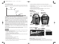
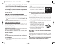
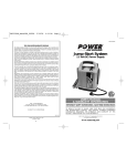
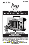
VEC012BBD_ManualEN_020106
2/1/06
3:13 PM
Page 12
VEC012BBD
TWO YEAR LIMITED WARRANTY PROGRAM
This limited warranty program is the only one that applies to this product, and it sets forth all the
responsibilities of Vector Manufacturing, regarding this product. There is no other warranty, other than
those described herein. Any implied warranty of merchantability or fitness for a particular purpose on
this product is limited in duration to the duration of this warranty.
This Vector Manufacturing product is warranted, to the original purchaser only, to be free of defects in
materials and workmanship for two years from the date of purchase without additional charge. The
warranty does not extend to subsequent purchasers or users. Manufacturer will not be responsible for
any amount of damage in excess of the retail purchase price of the product under any circumstances.
Incidental and consequential damages are specifically excluded from coverage under this warranty.
This product is not intended for commercial use. This warranty does not apply to damage to units from
misuse or incorrect installation/connection. Misuse includes wiring or connecting to improper polarity
power sources.
RETURN/REPAIR POLICY: Defective products may be returned to manufacturer. Any defective product
that is returned to manufacturer within 30 days of the date of purchase will be replaced free of charge.
If such a product is returned more than 30 days but less than two years from the purchase date,
manufacturer will repair the unit or, at its option, replace it, free of charge.
If the unit is repaired, new or reconditioned replacement parts may be used, at manufacturer’s option.
A unit may be replaced with a new or reconditioned unit of the same or comparable design. The
repaired or replaced unit will then be warranted under the terms of the remainder of the warranty
period. The customer is responsible for the shipping charges on all returned items. During the warranty
period, manufacturer will be responsible for the return shipping charges to the customer in the United
States.
LIMITATIONS: This warranty does not cover accessories, such as charging adapters, bulbs, fuses and
batteries, damage or defects resulting from normal wear and tear (including chips, scratches, abrasions,
discoloration or fading due to usage or exposure to sunlight), accidents, damage during shipping to our
service facility, alterations, unauthorized use or repair, neglect, misuse, abuse, failure to follow
instructions for care and maintenance, fire, flood and Acts of God.
If your problem is not covered by this warranty, call our Technical Support Department toll free at (800)
618-5178 for general repair information and charges if applicable. You may also contact us through
our website at www.vectormfg.com.
STATE LAW RIGHTS: This warranty gives you specific legal rights. Some states do not allow limitations
on how long an implied warranty lasts or the exclusion or limitation of incidental or consequential
damages, so the exclusions or limitations stated herein may not apply. This warranty gives the purchaser
specific legal rights; other rights, which vary from state to state, may apply.
TO REQUEST WARRANTY SERVICE FOR THIS PRODUCT: Contact Technical Support by telephone, fax
or mail (see below). We suggest that you keep the original packaging in case you need to ship the unit.
When returning a product, include your name, address, phone number, dated sales receipt (or copy)
and a description of the reason for return and product serial number. After repairing or replacing the
unit, we will make every effort to return it to you within four weeks.
WARRANTY ACTIVATION: Please complete Warranty Activation Card and mail to Vector
Manufacturing. Enter “VEC012BBD” as Model and “START-IT® Jump ’n Charge™” as Product Type. All
Vector products must be registered within 30 days of purchase to activate this warranty. Mail the
completed registration form, along with a copy of the original sales receipt, to:
with 450 Instant Starting Amps
12 Volt DC Power Supply • LED Emergency Area Light
IMPORTANT SAFETY INFORMATION, SAVE THESE
INSTRUCTIONS
WARRANTY IS NON-TRANSFERABLE.
BD020106
12
Smart™ Battery Charger/Jump-Starter
USER’S MANUAL
& WARRANTY INFORMATION
ATTN.: CUSTOMER SERVICE
4140 SW 30th Ave., Ft. Lauderdale, FL 33312
• TOLL FREE: (800) 618-5178 •
© 2006 VECTOR MANUFACTURING
MADE IN CHINA
START-IT® ™
Jump ’n Charge
TO REDUCE THE RISK OF INJURY, USER MUST READ AND UNDERSTAND
THIS INSTRUCTIONAL MANUAL. THIS MANUAL CONTAINS IMPORTANT
INFORMATION REGARDING THE OPERATION AND WARRANTY OF THIS
PRODUCT. PLEASE RETAIN FOR FUTURE REFERENCE.
4140 S.W. 30th Ave., Ft. Lauderdale, FL 33312 U.S.
Toll Free: (800) 618-5178
www.vectormfg.com
VEC012BBD_ManualEN_020106
2/1/06
3:13 PM
Page ii
IMPORTANT SAFETY INSTRUCTIONS
WARNINGS
1. RISK OF EXPLOSIVE GAS MIXTURES — WORKING IN THE VICINITY OF A LEAD-ACID
BATTERY IS DANGEROUS. BATTERIES GENERATE EXPLOSIVE GASES DURING
NORMAL BATTERY OPERATION. FOR THIS REASON, IT IS OF UTMOST IMPORTANCE
THAT EACH TIME BEFORE USING THIS UNIT, YOU READ THIS MANUAL AND FOLLOW
THE INSTRUCTIONS EXACTLY.
2. To reduce risk of battery explosion, follow these instructions and those published by
the battery manufacturer and manufacturer of any equipment you intend to use in
vicinity of battery. Review cautionary markings on these products and on engine.
3. This equipment employs parts (switches, relays, etc.) that produce arcs or sparks.
Therefore, if used in a garage or enclosed area, the unit MUST be placed not less
than 18 inches above the floor.
NOTE:
This unit is delivered in a partially charged state – you must fully charge it before using
it for the first time. Initial 120 volt AC charge time should be for 48 hours. See page 9.
Battery Safety
1. Use of an attachment not recommended or sold by the battery charger manufacturer may result in
a risk of fire, electric shock, or injury to persons.
2. To reduce risk of damage to electric plug and cord, pull by plug rather than cord when
disconnecting charger.
3. Do not operate unit with damaged cord or plug; or if the unit has received a sharp blow, been
dropped, or otherwise damaged in any way. Do not disassemble the unit; take it to a qualified
service technician when service or repair is required. Incorrect re-assembly may result in a risk of
electric shock or fire, and will void warranty.
4. To reduce risk of electric shock, disconnect the unit from any power source before attempting
maintenance or cleaning. Turning off controls without disconnecting will not reduce this risk.
5. Jump-start procedures should only be performed in a safe, dry, well-ventilated area.
6. Always store battery clamps on the clamp tabs on the back of the unit when not in use. Never touch
battery clamps together. This can cause dangerous sparks, power arcing and/or explosion.
7. When using this unit close to the vehicle’s battery and engine, stand the unit on a flat, stable surface,
and be sure to keep all clamps, cords, clothing and body parts away from moving vehicle parts.
8. Do not wear vinyl clothing when jump-starting a vehicle, friction can cause dangerous staticelectrical sparks. Remove all jewelry or metal objects that could cause short circuits or react with
battery acid.
9. NEVER ATTEMPT TO JUMP-START OR CHARGE A FROZEN BATTERY.
10. Do not charge the battery while the engine is operating.
11. See operating instructions for length of charge information.
12. Vehicles that have on-board computerized systems may be damaged if vehicle battery is jumpstarted. Before jump-starting, read the vehicle’s owner’s manual to confirm that external-starting
assistance is suitable.
13. Never allow battery acid to come in contact with this unit.
14. Never submerge this unit in water; and do not expose it to rain, snow or use when wet.
Personal Safety
1. Another person should be within range of your voice or close enough to come to your aid when
you work near a lead-acid battery.
2. Fresh water and soap should be nearby in case battery acid contacts skin, clothing, or eyes.
3. Wear complete eye protection and clothing protection. Avoid touching eyes while working with a
battery. Acid, acid particles or corrosion may get into eyes. Immediately flood eye with cold water
(Eye Wash Station) for at least 15 minutes and seek medical attention immediately.
4. If battery acid contacts skin or clothing, wash immediately with soap and water. If redness, pain or
irritation occurs, seek immediate medical attention.
5. NEVER smoke or allow a spark or flame in vicinity of battery or engine.
6. Be extra cautious to reduce the risk of dropping a metal tool onto battery. This might cause sparks
or short-circuit the battery or other electrical part, which can cause an explosion.
7. Remove personal metal items such as rings, bracelets, necklaces and watches when working with
a lead-acid battery. A lead-acid battery can produce a short-circuit current high enough to cause a
severe burn.
ii
8. Use charger for charging a LEAD-ACID battery only. It is not intended to supply power to a lowvoltage electrical system other than in a starter-motor application. Do not use the battery charger
for charging dry-cell batteries that are commonly used with home appliances. These batteries may
burst and cause injury to persons and damage property.
9. THIS UNIT IS NOT FOR USE BY CHILDREN AND SHOULD ONLY BE OPERATED BY ADULTS.
FIRST AID
SKIN: If battery acid comes in contact with skin, rinse immediately with water, then wash thoroughly with
soap and water. If redness, pain or irritation occurs, seek immediate medical attention.
EYES: If battery acid comes in contact with eyes, flush eyes immediately for a minimum of 15 minutes
and seek immediate medical attention.
Power Cord Safety
This appliance has a polarized plug (one blade is wider than the other) as a safety feature. This plug will
fit into a polarized extension cord only one way. If the plug does not fit fully into the outlet, reverse the
extension cord. Do not attempt to defeat this safety feature.
Preparing to Charge
1. Determine voltage of battery to be charged by referring to the vehicle manual.
2. If it is necessary to remove battery from vehicle to charge, or to clean terminals, always remove
grounded terminal from battery first. Make sure all accessories in the vehicle are off, so as not to
cause an arc.
3. Clean battery terminals. Do not allow corrosion to come in contact with eyes.
4. Add distilled water in each cell until battery acid reaches level specified by battery manufacturer.
This helps purge excessive gas from cells. Do not overfill. For a battery without cell caps
(maintenance free), carefully follow manufacturer's charging instructions.
5. Study all battery manufacturer’s specific precautions, such as removing or not removing cell caps
while charging, and recommended rates of charge.
6. Area around battery should be well ventilated while battery is being charged. Gas can be forcefully
blown away by using a piece of cardboard or other nonmetallic material as a fan.
7. Make sure the initial charging rate does not exceed battery manufacturer’s requirement.
Charger Location
1. Locate charger as far away from battery as cables permit.
2. NEVER place charger directly above battery being charged; gases from battery will corrode and
damage charger.
3. NEVER allow battery acid to drip on charger when reading gravity or filling battery.
4. NEVER operate charger in a closed-in area or restrict ventilation in any way.
5. Marine batteries must be removed and charged on shore.
6. Do not set a battery on top of charger.
Connection Precautions
1. Connect and disconnect battery clamps only after disconnecting AC extension cord from unit.
2. Never allow clamps to touch each other.
3. Attach clamps to battery chassis as indicated in “Battery Installed in Vehicle” steps 5 and 6, and
in “Battery Outside of Vehicle” steps 2, 4 and 5.
Follow these steps when the battery is installed in a vehicle. A spark near the
battery may cause an explosion. To reduce risk of a spark near the battery:
1. Position AC and DC cords to reduce risk of damage by hood, door, or moving engine part.
2. Stay clear of fan blades, belts, pulleys, and other parts that can cause injury to persons.
3. Check polarity of battery posts. POSITIVE (POS, P, +) battery post usually has larger diameter than
NEGATIVE (NEG, N, –) post.
4. Determine which post of battery is grounded (connected) to the chassis. If NEGATIVE post is
grounded to chassis (as in most vehicles), see 5. If POSITIVE post is grounded to the chassis, see 6.
5. For negative-grounded vehicle, connect POSITIVE (RED) clamp from battery charger to POSITIVE
(POS, P, +) ungrounded post of battery. Connect NEGATIVE (BLACK) clamp to vehicle chassis or
engine block away from battery. Do not connect clip to carburetor, fuel lines, or sheet-metal body
parts. Connect to heavy gauge metal part of the frame or engine block.
6. For positive-grounded vehicle, connect NEGATIVE (BLACK) clamp from battery charger to
NEGATIVE (NEG, N, –) ungrounded post of battery. Connect POSITIVE (RED) clamp to vehicle
chassis or engine block away from battery. Do not connect clip to carburetor, fuel lines or sheetmetal body parts. Connect to a heavy gauge metal part of the frame or engine block.
iii
VEC012BBD_ManualEN_020106
2/1/06
3:13 PM
Page iv
7. When disconnecting charger, disconnect AC cord, remove clamp from vehicle chassis, and then
remove clamp from battery terminal.
8. Do not charge the battery while the engine is operating.
9. See operating instructions for length of charge information.
Follow these steps when the battery has been removed from a vehicle. A
spark near the battery may cause an explosion. To reduce risk of a spark
near the battery:
1. Check polarity of battery posts. POSITIVE post (marked POS,P, +) usually has a larger diameter than
the NEGATIVE battery post (marked NEG, N, –).
2. Attach a 24-inch (minimum length) 6 AWG insulated battery cable to the NEGATIVE battery post
(marked NEG, N, –).
3. Connect the POSITIVE (RED) battery clamp to the POSITIVE battery post (marked POS, P, + or red).
4. Stand as far back from the battery as possible, and do not face battery when making final
connection.
5. Carefully connect the NEGATIVE (BLACK) charger clamp to the free end of the battery cable
connected to the NEGATIVE terminal.
6. Set the charge rate to appropriate setting according to battery size.
7. When disconnecting charger, always do so in reverse sequence of connecting procedure and
break first connection while as far away from battery as practical.
Note: A marine (boat) battery must be removed and charged on shore. To charge it
on board requires equipment specifically designed for marine use. This unit
was NOT designed for such use.
Read This User’s Manual Before Using This Unit.
SAVE THESE INSTRUCTIONS
TABLE OF CONTENTS
Introduction . . . . . . . . . . . . . . . . . . . . . . . . . . . . . . . . . . . . . . . . . . . . . . . . . .
Features . . . . . . . . . . . . . . . . . . . . . . . . . . . . . . . . . . . . . . . . . . . . . . . . . . . .
1
2
Controls and Indicators . . . . . . . . . . . . . . . . . . . . . . . . . . . . . . . . . . . . . . . .
3
Using the Battery Charger . . . . . . . . . . . . . . . . . . . . . . . . . . . . . . . . . . . . . . . .
2
Charge Rate Selection . . . . . . . . . . . . . . . . . . . . . . . . . . . . . . . . . . . . . . . .
5
Charging the Battery . . . . . . . . . . . . . . . . . . . . . . . . . . . . . . . . . . . . . . . . .
5
Automatic Float Charging . . . . . . . . . . . . . . . . . . . . . . . . . . . . . . . . . . . . . .
5
Alternator Check . . . . . . . . . . . . . . . . . . . . . . . . . . . . . . . . . . . . . . . . . . . .
5
Approximate Charging Times . . . . . . . . . . . . . . . . . . . . . . . . . . . . . . . . . . .
6
Using the Jump-Starter . . . . . . . . . . . . . . . . . . . . . . . . . . . . . . . . . . . . . . . . . . .
7
Using the 12 Volt DC Power Supply . . . . . . . . . . . . . . . . . . . . . . . . . . . . . . . . .
8
Estimated 12 Volt DC Operation Time . . . . . . . . . . . . . . . . . . . . . . . . . . . . .
8
Using the Emergency LED Area Light . . . . . . . . . . . . . . . . . . . . . . . . . . . . . . . .
8
Care and Maintenance . . . . . . . . . . . . . . . . . . . . . . . . . . . . . . . . . . . . . . . . . .
8
Charging/Recharging . . . . . . . . . . . . . . . . . . . . . . . . . . . . . . . . . . . . . . . . .
8
Replacement Parts . . . . . . . . . . . . . . . . . . . . . . . . . . . . . . . . . . . . . . . . . . .
9
Fuse Replacement . . . . . . . . . . . . . . . . . . . . . . . . . . . . . . . . . . . . . . . . . . . . 10
Battery Disposal . . . . . . . . . . . . . . . . . . . . . . . . . . . . . . . . . . . . . . . . . . . . . 10
Troubleshooting . . . . . . . . . . . . . . . . . . . . . . . . . . . . . . . . . . . . . . . . . . . . . . . 10
Display Indications/Common Problems/Possible Solutions . . . . . . . . . . . . . . . 10
Specifications . . . . . . . . . . . . . . . . . . . . . . . . . . . . . . . . . . . . . . . . . . . . . . . . . 11
INTRODUCTION
Thank you for choosing the Black & Decker 2/6/10 Amp Smart™ Battery
Charger/Jump-Starter. The Jump-Starter is a compact, durable, portable jumpstart system for vehicles and boats that have a standard 12 volt battery system. This
self-contained, rechargeable system will start most vehicles and boats without the
need for a host vehicle or 120 volt AC power supply.
The VEC012BBD can also be used as a safe, portable source of 12 volt DC
electric power for use with 12 volt DC cordless, rechargeable products and DC/AC
power inverters.
The unit’s long-life LED Emergency Area Light provides proper lighting for changing
a tire or connecting the unit to a battery.
The Battery Charger has a high charge rate of up to 10 amps, and low charge
rate of 2 amps. It is designed for charging only 12-volt lead-acid batteries —
conventional automotive, maintenance-free, marine deep cycle and gel — used in
cars, farm equipment, boats, RVs and SUVs, lawn mowers/garden tractors,
motorcycles, personal watercraft, snowmobiles, ATVs and various applications.
Please read this guide carefully before use to ensure optimum performance and
avoid damage to the unit or items that you are using it with.
iv
1
VEC012BBD_ManualEN_020106
2/1/06
3:13 PM
Page 2
Smart™ Battery Charger
Smart™ Battery Chargers feature 3-stage, high-efficiency charging technology, built-in
microprocessor control that ensures fast, safe and complete charging of serviceable
batteries.
STAGE ONE
BEEP
BEEP
• Includes non-spillable, maintenance-free, heavy-duty, sealed battery
• Rechargeable with either supplied 12 Volt DC Charging Adapter or built-in 120
Volt AC Charger
• Heavy duty, industrial grade copper clamps, and #6AWG jumper cables with
exclusive recessed cable holsters
• Requires no maintenance (other than recharging) for optimum operation
• Molded high-impact case is tough and durable
FRONT VIEW
STAGE TWO
12 VOLT DC
OUTLET
STAGE THREE
OFF BEEP
CHARGING
COMPLETE
Stage One — Rapid Start Charge at 10 amps delivers maximum charging
amperage to “wake up” any serviceable 12 volt battery and allows for quick engine
starting in just 8 minutes (based on a midsize vehicle battery at 50% charge level).
When battery reaches a maximum safe predetermined voltage, the charger will
automatically signal a "beep" and move into Stage 2 of the charging process.
Stage Two — Absorption Charge maintains the maximum possible charge at a
constant, safe, predetermined voltage. During the phase, voltage absorption regulation
charge, the charging voltage remains constant, while the actual charging current is
reduced to allow for the maximum proper internal chemical energy transfer. At the end
of Stage 2, the charger will automatically move into Stage 3 charge mode.
Stage Three — Top-Off Charge voltage is automatically maintained and reduced
to a predetermined level while current is adjusted for a safe, effective battery charge.
At the conclusion of Stage 3, the unit will BEEP signaling the completion of the
charging cycle.
The Automatic Float Charge feature is ideal for maintaining a battery. It automatically
“tops off” a battery as needed, to keep it fully charged all the time.
FEATURES
• Smart™ Battery Charger with three charge rate settings, accessed by the Charge
Rate Selector 2A/6A/10A button:
a) 2 amps: smaller batteries, as in lawn mowers, snowmobiles, motorcycles, etc.
b) 6 amps: mid-sized batteries, as in small cars
c) 10 amps: automobile batteries and light trucks
• Digital Display shows charge rate, operating mode, fault codes and FUL when charged
• Alternator Check
• Automatic Float Charge
• Jump-Starts without the need of another vehicle
• Reverse polarity connection warning
• Easy-to-Read LED Battery Charge Level Indicators
• 12 Volt DC Outlet for powering and recharging accessories and appliances
• Ultra bright, long-life LED emergency area light
BATTERY CHARGE
LEVEL BUTTON
BATTERY CHARGER
PANEL (BACK OF UNIT)
(SEE BELOW FOR DETAILS)
AREA LIGHT
POWER
SLIDE
SWITCH
LED EMERGENCY
AREA LIGHT
120 VOLT AC
CHARGER
LED BATTERY STATUS
INDICATORS
NEGATIVE (–)
RED CLAMP
POSITIVE (+)
RED CLAMP
Controls and Indicators
DIGITAL DISPLAY
2
BACK VIEW
GOOD/BAD POLARITY
CONNECTION INDICATORS
BATTERY
VOLTAGE
BUTTON
2/6/10 AMP
BUTTON
ALTERNATOR
CHECK BUTTON
POWER BUTTON
DIGITAL READOUT
CIRCULATING PATTERN
FAULT LED ALTERNATOR GOOD
INDICATOR LED INDICATOR
BATTERY VOLTAGE
LED INDICATOR
FUNCTION BUTTONS (FROM LEFT TO RIGHT):
Battery Voltage — Displays the battery’s current voltage.
2/6/10 AMP (Charge Rate Selector) — allows the user to select the charge rate
based on battery size. This selection and the actual battery charge rate are monitored
3
VEC012BBD_ManualEN_020106
2/1/06
3:13 PM
Page 4
by the microprocessor. The charger will stop charging if the rate is too fast or too slow
for the battery size or condition.
Alternator Check — is a quick check that measures the battery voltage. This check
is repeated at various electrical load levels and the tests allow the user to determine
if the alternator can keep up with the loads.
DIGITAL DISPLAY:
Large 3-Character Digital Display in the upper left of the control panel indicates
the various conditions and/or status codes:
Status Codes are described in the following chart and on the back of the unit.
AC POWER INDICATOR - When connected to an AC outlet, digital display shows circulating pattern to
indicate power is on. Disconnect charger after use.
FAULT CODES
F01
F02
F03
F04
F05
F06
F07
INTERNAL SHORTED CELL BATTERY - Cannot be charged. Have battery checked by certified auto service center.
EXCESSIVE LOAD ON BATTERY WHILE CHARGING - Check load.
BAD BATTERY CONNECTION - Check battery connection.
BATTERY VOLTAGE TOO LOW TO ACCEPT CHARGE - Have battery checked by certified auto service center.
INTERNAL OPEN CELL - Have battery checked by certified auto service center.
SULFATED CONDITION - Battery needs to be reconditioned. See manual.
OVERTIME CONDITION - Battery will not accept a charge after 18 hours of continuous charging. Battery may have
internal damage. Have battery checked by certified auto center.
BATTERY CHARGE RATE IS SET TOO LOW - Set charger to higher charge rate. See manual.
OVERHEATED CONDITION - Disconnect charger and allow to cool for 30 min., check for ample ventilation.
REVERSE POLARITY
ALTERNATOR OUTPUT IS OUT OF TYPICAL OPERATION RANGE
OPERATION CODES
000
FUL
BATTERY RECONDITIONING - (The letters DES will display for the first 3 seconds.)
ALTERNATOR VOLTAGE CHECK
CHARGER STANDBY
BATTERY FULLY CHARGED
CONTROL PANEL LED INDICATORS:
POWER — lights when either the Battery Charger or Jump-Starter is turned ON.
FAULT — lights when when a fault condition is present. The Digital Display will show
the appropriate Fault Code (refer to the chart above, which can also be found on the
back of the unit). Consult the above Status Code Chart for more information.
ALTERNATOR GOOD — lights at the conclusion of the Alternator Check to indicate
alternator voltage is within operating range. (Otherwise, the Digital Display with
show F07.)
USING THE BATTERY CHARGER
Ensure that all installation and operating instructions, and safety
precautions are understood and carefully followed by anyone
installing or using the charger. Follow the steps outlined in the
“Important Safety Instructions” at the front of this User’s Manual.
Charge Rate Selection
After charger clamps are correctly connected, plug the charger into a 120 volt AC
outlet. The power indicator light will light. Select the proper charge current rate based
on battery size.
WARNING
If FAULT indicator lights and the Digital Display shows “F02”, the
connection to the battery terminals is bad. Follow the steps outlined in
“Important Safety Instructions” at the front of this manual.
If Rev. Polarity indicator also lights, the RED (POSITIVE) and BLACK
(NEGATIVE) clamps are incorrectly connected to battery terminals.
Follow the steps outlined in “Important Safety Instructions” at the
front of this manual.
Charging the Battery
1. Press Charge Rate Selector 2A/6A/10A button once to begin charging at the
2 amp rate; the unit sounds a beep and the charging current LED lights.
2. Pressing the Charge Rate Selector 2A/6A/10A button again advances charging
rate to 4 amps, and pressing once more advances charging rate to 6 amps.
(Pressing the button again will turn OFF the charger output.) This selection
and actual battery charge rate are monitored by the microprocessor and the
unit will stop charging if the selected rate is too fast or too slow for battery size
or condition.
As the battery nears full charge capacity, the unit’s output will automatically drop
to a lower charge rate.
3. The FUL LED lights when the battery is fully charged.
4. Disconnect the AC power cord first, then the NEGATIVE clamp, and finally the
POSITIVE clamp.
Automatic Float Charging
Automatic Float Charging is ideal for maintaining a fully charged battery.
1. Keep the 120 volt AC power and battery connected after battery is fully charged.
2. The charger monitors the battery and tops it off as needed.
WARNING
If battery size is not known, charge at the 2 Amp rate. DO NOT
overcharge batteries.
4
5
VEC012BBD_ManualEN_020106
2/1/06
3:13 PM
Page 6
USING THE JUMP-STARTER
Alternator Check
Part 1
No Load
(Turn OFF all vehicle’s accessories): The battery must be fully charged
before testing the alternator. Run the engine long enough to achieve
normal idle speed and verify there is a no-load voltage.
1. Press Alternator Check to start the check.
2. Alternator Good LED will light to indicate the alternator is good, or F07
will display if alternator output voltage is out of typical operation range.
3. Press Alternator Check again to stop the test.
Part 2
Under Load (Accessories ON): Next, load the alternator by turning on as many
accessories as possible (except for A/C and DEFROST)
1. Press Alternator Check to start the check.
2. Alternator Good LED will light to indicate the alternator is good, or F07
will display if alternator output voltage is out of typical operation range.
3. Press Alternator Check again to stop the test.
If the first alternator check indicates a good alternator and the second indicates the
alternator is bad, the problem could stem from: loose fan belts, an intermittent diode
failure or possibly bad connections between the battery and alternator and/or ground.
Notes: The Battery Charge Level Button button is disabled in Alternator Check
mode.
F07 may display because someone has added a number of accessory loads
on the charging system, thereby increasing current demand from the
alternator. MAKE SURE THAT THE ALTERNATOR IS RATED TO SUPPORT THE
APPLICATION.
This check may not be accurate for every make, manufacturer and model of
vehicle.
Check only 12 volt systems.
Approximate Charging Times
The 2/6/10 Amp 12 Volt Smart Battery Charger will automatically adjust the
charge rate as the battery becomes charged and stop when the battery is fully
charged. Deep cycle batteries may require longer charging time.
For estimates of the time it takes to charge a battery, refer to the following table.
Percent of charge
in battery
This Jump-Starter is equipped with Good/Bad Polarity Indicators. Energy will only
flow when proper connections are made to the battery and frame. Once the
connections are properly made, follow the steps below to jump-start the vehicle.
1. Turn OFF vehicle ignition and all accessories (radio, A/C, lights, connected cell
phone chargers, etc.). Place vehicle in “park” and set the emergency brake.
2. Make sure the unit is disconnected from all charging power sources.
3. Remove jumper clamps from clamp tabs. Connect the RED clamp first,
then the BLACK clamp.
4. Procedure for jump-starting a NEGATIVE GROUNDED SYSTEM (negative
battery terminal is connected to chassis) (MOST COMMON)
4a. Connect POSITIVE (+) RED clamp to vehicle battery’s POSITIVE terminal.
4b. Connect NEGATIVE (–) BLACK clamp to chassis or a solid, non-moving,
metal vehicle component or body part. NEVER CLAMP DIRECTLY TO
NEGATIVE BATTERY TERMINAL OR MOVING PART.
5. Procedure for jump-starting POSITIVE GROUND SYSTEMS
Note: In the rare event that the vehicle to be started has a POSITIVE GROUNDED
SYSTEM (positive battery terminal is connected to chassis), replace steps 4a
and 4b above with steps 5a and 5b, then proceed to step 6.
5a. Connect NEGATIVE (–) BLACK clamp to vehicle battery’s NEGATIVE terminal.
5b. Connect POSITIVE (+) RED CLAMP to vehicle chassis or a solid, nonmoving, metal vehicle component or body part. NEVER CLAMP DIRECTLY
TO POSITIVE BATTERY TERMINAL OR MOVING PART.
6. When clamps are connected properly, press the Power Button on the back of the
unit (see the diagram on page 3) to turn the unit ON.
7. Turn ON the vehicle ignition and crank the engine in 5-6 second bursts until
engine starts.
8. Press the Power Button on the back of the unit once more to turn the unit OFF.
9. Disconnect the NEGATIVE (–) engine or chassis clamp first, then disconnect the
POSITIVE (+) battery clamp.
FOLLOW ALL SAFETY INSTRUCTIONS FOUND ON PAGES ii THRU iv OF
THIS OWNER’S MANUAL.
CAUTIONS
75%
50%
25%
0%
at 2 amp rate
7 HRS
14 HRS
NR*
at 6 amp rate
2.5 HRS
4.7 HRS
7 HRS
9.2 HRS
NR*
at 10 amp rate
1.4 HRS
2.8 HRS
4.2 HRS
5.5 HRS
*NR = Not recommended at 2 amps — use a higher charge rate.
The times shown in the table above are approximate and refer to a 50 Ah automotive
battery. For example, a 50 Ah (12 volt) battery is discharged (50%). How long
should it be charged at the 6 amp rate? See the chart above under “50%” and “at
6 amp rate.”
In most cases, battery charging times will vary depending on the size, age and
condition of the battery. Smaller batteries should be charged at a lower rate (2 amps)
and an extra hour added to charge time.
6
• If the Reverse Connection LED on the front of the unit lights (and the Digital Display
shows “F06”) after clamps are connected to vehicle battery, polarity is wrong.
Reverse the clamp connections.
• If vehicle fails to start, turn OFF the vehicle ignition, turn OFF the Jump-Starter,
disconnect the jump-start system’s leads and investigate why the engine did not
start.
• Recharge this unit fully after each use.
WARNINGS
• Make sure the unit is disconnected from all charging power sources
before beginning the jump-starting procedure.
• This power system is to be used ONLY on vehicles or boats with
12 volt DC battery systems.
7
VEC012BBD_ManualEN_020106
2/1/06
3:13 PM
Page 8
• Never touch RED and BLACK clamps together — this can cause
dangerous sparks, power arcing, and/or explosion.
• Vehicles that have on-board computerized systems may be
damaged if vehicle battery is jump-started. Before jump-starting this
type of vehicle, read the vehicle owner’s manual to confirm that
external-starting assistance is advised.
• Excessive engine cranking can damage the vehicle‘s starter motor. If
the engine fails to start after the recommended number of attempts,
discontinue jump-start procedure and look for other problems that
need to be corrected.
• After use, turn the VEC012BBD OFF by pressing the Power Button on
the back of the unit.
USING THE 12 VOLT DC PORTABLE POWER SUPPLY
This portable power source is also for use with all 12 volt DC accessories equipped
with a male accessory outlet plug and are rated up to 5 amps.
1. Lift up the cover of the unit ‘s 12 volt DC outlet.
2. Insert the 12 volt DC plug from the appliance into the 12 Volt DC Outlet on the
front of the unit (see the diagram on page 3). DO NOT EXCEED A 5 AMP
LOAD.
3. Switch on the appliance and operate as usual.
4. Periodically press the battery charge level pushbutton to check battery status.
USING THE EMERGENCY LED AREA LIGHT
The Emergency LED Area Light is controlled by the Area Light Power Switch on the
front panel of the unit (see page 3). Make sure the lamp is turned OFF when the
unit is being recharged or stored.
CARE AND MAINTENANCE
This product has a sealed lead acid battery that should be kept fully charged.
Recharge before first use, immediately after each use, and once a month if not used.
Failure to do this may reduce the battery life dramatically.
Note: This unit is delivered in a partially charged state – you must fully charge it
before using it for the first time. Initial AC charge should be for 48 hours.
Charging/Recharging
For maximum battery life, we recommend the unit be kept fully charged at all times.
If the battery is allowed to remain in a discharged state, battery life will be
shortened.
Note: Recharging battery after each use will prolong battery life; frequent heavy
discharges between recharges and/or overcharging will reduce battery life.
120 Volt AC Recharge
1. Connect a standard household extension cord to the 120 Volt AC Charger on
the back of the unit.
8
2. Plug the other end of the cord into a standard North American 120 volt AC wall
outlet.
3. Charge until the green (FULL) Battery Status LED Indicator on the front of the unit
lights.
3. After initial charge, recharge this device as necessary
for at least 14-16 hours or until the green (FULL)
Battery Status LED Indicator on the front of the unit
lights. Recharge at least once a month when not in
frequent use.
4. When charging is complete, disconnect the
extension cord.
Note: The unit cannot be overcharged using the AC method. The unit also comes with
a DC/DC charging adapter for recharging the unit from a vehicle’s 12 volt DC
accessory outlet.
12 Volt DC Charging
The DC recharging method will NOT recharge the unit as effectively as recharging
using the 120 volt AC method. The 12 volt DC recharging method is recommended
only when it is necessary, since frequent use of the 12 volt DC recharging procedure
may shorten the battery system’s life.
1. Insert the gold-tipped end of the 120 Volt DC Charging Adapter into the
vehicle’s 12 volt DC accessory outlet.
2. Insert the silver-tipped end plug into the 12 volt DC accessory outlet on the front
panel of the unit.
3. To check the charge status of the battery during DC
charging, disconnect the DC adapter from the
accessory outlet and push the Battery Charge Level
pushbutton. Observe the LED battery Status
Indicators. The green (FULL) Battery Status Indicator
will light when when charging is complete (however,
observe the warning below and do not recharge for
more than 5-6 horus using this method).
4. When charging is complete, remove the power cord
and return it to the storage compartment.
WARNING
Do not recharge for more than 5 to 6 hours maximum using the 12
volt DC method.
Replacement Parts
For replacement parts (charging adapters, charging adapter fuses, etc.), contact
Technical Support, toll free at (800) 618-5178. For most parts replacement, it is
recommended that the unit be returned to the manufacturer.
WARNING
Do not operate unit if there is any evidence of damage. The product
must be returned to Black & Decker for testing and repair. Replace any
damaged Charging adapters immediately before further use.
9
VEC012BBD_ManualEN_020106
2/1/06
3:13 PM
Page 10
Fuse Replacement (DC Charger Adapter)
1. Remove the plug from the accessory receptacle. Remove the gold cap by
turning counterclockwise and lifting off.
2. Remove the center pin and spring. Remove the fuse.
3. Replace the fuse with a same type and size fuse (8 amp).
4. Replace the center pin and spring inside the plug.
5. Replace the gold cap by turning clockwise onto the plug.
Battery Replacement
It is recommended that the unit be returned to manufacturer for battery replacement.
Contact Customer Service, toll-free, at (800) 618-5178.
Battery Disposal
Contains a maintenance-free, sealed, non-spillable, lead acid
battery, which must be disposed of properly. Recycling is
required — contact your local authority for information. Failure
to comply with local, state and federal regulations can result in
fines or imprisonment. For more information on recycling this
battery, call toll-free (800) 822-8837.
WARNINGS
Do not dispose of the battery in fire, as this may result in an explosion.
Before disposing of the battery, protect exposed terminals with
heavy-duty electrical tape to prevent shorting (shorting can result in
injury or fire).
Do not expose battery to fire or intense heat, as it may explode.
• If the situation persists after reconditioning and equalizing, we recommend taking
your battery to a certified automotive service center for evaluation.
F04 — Overtime Condition
Appears when charging time exceeds 18 hours. You may be using a charge current
rate too low for a large battery. Select a higher charge rate to charge the battery.
F05 — Overheated Condition
The ventilation grill that prevents the air from flowing in and out of the charger may
be blocked.
• Follow the steps outlined in “Important Safety Instructions” at the front of this manual to
disconnect AC cord and clamps, allow the unit to cool for 30 minutes and reconnect.
• Make sure there is ample ventilation before resuming operation.
F06 — Reverse Polarity
The connections to the battery’s POSITIVE and NEGATIVE terminals are incorrect.
Follow the steps outlined in “Important Safety Instructions” at the front of this manual
to disconnect AC cord and clamps and reconnect to battery with correct polarity.
F07 — Alternator Voltage
Alternator output voltage is out of typical operation range.
Charging a Very Cold Battery
If the battery to be charged is very cold (in temperatures below freezing — 0°C/ 32°F),
it cannot accept a high rate of charge. The initial charge rate will be low. The charge
rate will increase as the battery warms. Never attempt to charge a frozen battery.
SPECIFICATIONS
TROUBLESHOOTING
Display Indications/Common Problems/Possible Solutions
No Functions
• Check and make sure the charger is plugged into a live 110/120 volt AC outlet.
• Follow the steps outlined in the Operating Instructions section.
F01 — Internal Shorted Cell Battery
If the battery being charged has an internal shorted cell, the F01 will show. We
recommend taking your battery to a certified automotive service center for evaluation.
F02 — Bad Battery Connection or Battery Voltage Too Low to Accept
Charge
When F02 appears, the most common cause is poor connection to battery.
• Follow the steps outlined in “Important Safety Instructions” at the front of this manual
to disconnect AC cord and clamps, clean battery terminal and reconnect.
• If the situation persists, we recommend taking your battery to a certified automotive
service center for evaluation.
F03 — Sulfate or Unchargeable Battery
Appears when the battery is highly sulfated and cannot accept normal charge current.
• Follow the steps in “Recondition Mode” to recondition the battery.
• Follow the steps in “Equalizing” to equalize the battery.
10
Boost Ampere:
450 instantaneous cranking amps
Battery Type:
Sealed, high energy density, AGM, lead-acid,
rechargeable, maintenance-free, 12 volt DC
Area Light:
Light Emitting Diode (LED)
Booster Cables:
Heavy duty welding cable with
450 Amp copper clamps
Accessory Outlet:
Self-resetting breaker 5 amps
DC Charging Adapter: 12 volt DC
11