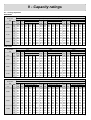
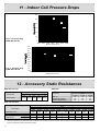
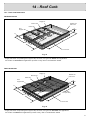
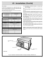
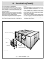
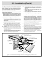
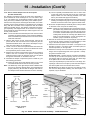
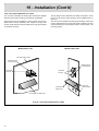
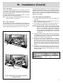
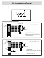
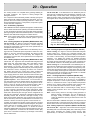
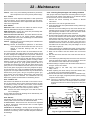
1
ROOFTOP
YORK
®
List of Contents
Page
1 - Description..........................................................................................................................................................................................................................4
2 - Product Nomenclature .........................................................................................................................................................................................4
3 - Features ..................................................................................................................................................................................................................................5
3.1
3.2
3.3
3.4
3.5
3.6
3.7
3.8
3.9
3.10
3.11
3.12
3.13
45678-
- Convertible airflow design ...............................................................................................................................................................................5
- Wide range of indoor airflows.......................................................................................................................................................................5
- Full perimeter base rails ..................................................................................................................................................................................5
- Electrical supply connections .......................................................................................................................................................................5
- 24VAC control circuit ..........................................................................................................................................................................................5
- Multiple refrigerant circuits .............................................................................................................................................................................5
- Durable construction ..........................................................................................................................................................................................5
- Low noise ..................................................................................................................................................................................................................5
- Compressors ...........................................................................................................................................................................................................5
- System protection ................................................................................................................................................................................................5
- Gas burner ................................................................................................................................................................................................................5
- Air filters ......................................................................................................................................................................................................................5
- Electrical control box ..........................................................................................................................................................................................5
Technical Specifications ....................................................................................................................................................................................6
Electrical Data .................................................................................................................................................................................................................6
Indoor fan characteristics ................................................................................................................................................................................7
Operating Limits ..........................................................................................................................................................................................................7
Accessories .......................................................................................................................................................................................................................7
8.1
8.2
8.3
8.4
8.5
8.6
8.7
8.8
8.9
8.10
8.11
8.12
- Dual input electronic enthalpy economizer..........................................................................................................................................7
- Motorized outdoor air intake damper.......................................................................................................................................................7
- Barometric relief/fixed outdoor air intake damper assembly (models 090 - 120 - 150) .........................................8
- Fixed outdoor air intake damper (models 180-240-300) ............................................................................................................8
- Barometric relief damper (models 180-240-300) .............................................................................................................................8
- Anti-recycle timers ...............................................................................................................................................................................................8
- Low ambient kit ......................................................................................................................................................................................................8
- Roof curbs .................................................................................................................................................................................................................8
- High speed drive ...................................................................................................................................................................................................8
- Propane conversion kit .....................................................................................................................................................................................8
- Dirty filter pressure switch ..............................................................................................................................................................................8
- Smoke detection ...................................................................................................................................................................................................8
9 - Capacity Ratings .........................................................................................................................................................................................................9
9.1 - Cooling Capacities ...............................................................................................................................................................................................9
9.2 - Gas Heat Application Data ..........................................................................................................................................................................11
10 11 12 13 14 -
Blower Performance .............................................................................................................................................................................................11
Indoor coil pressure drops ..........................................................................................................................................................................14
Accessory Static Resistances .................................................................................................................................................................14
Dimensions......................................................................................................................................................................................................................15
Roof Curb ..........................................................................................................................................................................................................................19
14.1 - Roof Curb Dimensions ...................................................................................................................................................................................19
14.2 - Unit and Curb Application ............................................................................................................................................................................20
15 - Safety ......................................................................................................................................................................................................................................20
16 - Inspection ..........................................................................................................................................................................................................................21
17 - Positioning .......................................................................................................................................................................................................................21
17.1 - Location ...................................................................................................................................................................................................................21
17.2 - Rigging and Handling .....................................................................................................................................................................................21
2
List of Contents
Page
18 - Lifting and Handling .............................................................................................................................................................................................22
19 - Installation ........................................................................................................................................................................................................................22
19.1
19.2
19.3
19.4
19.5
19.6
19.7
19.8
19.9
19.10
19.11
19.12
19.13
19.14
19.15
- Ductwork .................................................................................................................................................................................................................22
- Condensate Drain .............................................................................................................................................................................................22
- Filters .........................................................................................................................................................................................................................23
- Barometric relief/fixed outdoor air intake damper assembly .................................................................................................23
- Fixed outdoor air intake damper ..............................................................................................................................................................25
- Optional economiser rain hood (models 090-150) ......................................................................................................................25
- Optional economiser rain hood (models 180-240-300) ............................................................................................................26
- Power exhaust damper and rain hood option (models 180-240-300).............................................................................27
- Vent and combustion air hoods................................................................................................................................................................28
- Gas piping ..............................................................................................................................................................................................................29
- Gas connection ...................................................................................................................................................................................................29
- Gas piping recommandations ....................................................................................................................................................................29
- Power wiring .........................................................................................................................................................................................................30
- Digital thermostat ART TH 002 (DSL 700)........................................................................................................................................30
- Programmable thermostat ARTTP001 (SMS-1) ............................................................................................................................30
20 - Operation............................................................................................................................................................................................................................31
20.1
20.2
20.3
20.4
20.5
20.6
20.7
20.8
20.9
20.10
20.11
20.12
20.13
20.14
20.15
20.16
- Preliminary operation ......................................................................................................................................................................................31
- Cooling sequence of operation (models 090- 12 -150) ............................................................................................................31
- Heating sequence of operation (models 090- 12 -150) ............................................................................................................31
- Cooling sequence of operation (models 180-240-300) ............................................................................................................31
- Heating sequence of operation (models 180-240-300) ............................................................................................................31
- Economizer with dual enthalpy sensor................................................................................................................................................32
- Enthalpy setpoint adjustment .....................................................................................................................................................................32
- Economizer with exhaust fan option available with D2IG 180-240-300 ........................................................................32
- Motorized outdoor air dampers ................................................................................................................................................................33
- Pre-start check list (gas burner)...............................................................................................................................................................33
Post-start check list (gas) ..............................................................................................................................................................................33
- Manifold gas pressure adjustment (models 090-120-150) .....................................................................................................33
- Manifold gas pressure adjustment (models 180-240-300) .....................................................................................................34
- To check the supply air volume after the initial balancing has been completed (models 090 to 150) .................................34
- To check the supply air volume after the initial balancing has been completed (models 180-240-300).............................35
21 - System Protections ...............................................................................................................................................................................................35
21.1 - Lockout control ....................................................................................................................................................................................................35
22 - Maintenance ...................................................................................................................................................................................................................36
22.1
22.2
22.3
22.4
22.5
- Filters .........................................................................................................................................................................................................................36
- Motors .......................................................................................................................................................................................................................36
- Outdoor coil ...........................................................................................................................................................................................................36
- Burner .......................................................................................................................................................................................................................36
- Cleaning flue passages and heating elements ..............................................................................................................................36
23 - Fault Analysis ...............................................................................................................................................................................................................37
23.1 - General.....................................................................................................................................................................................................................37
23.2 - Troubleshooting ..................................................................................................................................................................................................37
3
1 - Description
The D2IG units are highly efficient single package air cooled air
conditioners and gas heating units.
ducting with unit sizes 180, 240 and 300.
- Low ambient controls for operation down to -18°C ambient
temperatures (not heat pump models).
The D2IG series includes 6 model sizes of cooling and gas heating.
- Anti-recycle timers.
These units are suitable for outdoor installation either on a roof
or at ground level.
- Roof curb - to enable building work on site to be completed
quickly and easily. They provide a water-tight seal between the
unit and the completed roof and allow ductwork to be completed prior to delivery of the D2IG unit.
They are completely assembled, piped, wired and charged with
refrigerant at the factory to provide one piece shipment and rigging, then quick and easy field installation.
- Alternative drive kits for indoor air fan to meet a variety of air
flow requirements on model 090 and above.
Accessories
An extensive list of either factory installed or field fitted options
are available to enhance the design flexibility of D2IG series
rooftops.
- Propane conversion kit.
- Adjustable Dirty Filter pressure switch.
- Economiser control - An advanced electronic dual enthalpy
sensor system developped in collaboration with Johnson
Controls to permit maximised reliability in non-mechanical
cooling using outdoor air.
- Smoke detection opens the outdoor air dampers and stops
the unit. Delivered with an ionic detector and an “NF” approved
electronics board.
- Motorised outdoor air systems.
- Digital Thermostat.
- Fixed outdoor and barometric relief air damper.
- Programmable Thermostat.
- Side duct connections : 25mm connection tabs replace the
side discharge and return panels to allow the use of side return
N.B. : Please check with YORK which of the above are available as factory fitted or customer fitted options.
2 - Product Nomenclature
D
2
I
G
1
8
0
G
3
2
0
5
0
PRODUCT CATEGORY
VOLTAGE CODE
D = Single Package Air Conditioner
(Air Cooled)
50 = 400/415-3+N-50
PRODUCT GENERATION
NOMINAL GAS HEATING
OUTPUT CAPACITY
1 = 1st Generation
2 = 2nd Generation
165 = 47.2 kW
200 = 56.6 kW
320 = 75.8 kW
400 = 94.0 kW
NOMINAL COOLING
CAPACITY
PRODUCT IDENTIFIER
IG = Mechanical Cooling with
Gas Furnace
4
090 = 25.5 kW
120 = 31.9 kW
150 = 42.8 kW
180 = 49.8 kW
240 = 61 kW
300 = 91 kW
REFRIGERANT TYPE
G = R407C Refrigerant
3 - Features
3.1 - Convertible airflow design
For maximum flexibility all models can be adapted for downflow
or horizontal airflow by simply removing two panels (either bottom or side) at the time of installation.
This approved coating system has passed the 250 hour, 20 %
salt spray test as per ASTM Standard B117.
3.8 - Low noise
All YORK package air conditioners operate at extremely low
sound level.
3.2 - Wide range of indoor airflows
Compressors are mounted on vibration isolators.
All models operate over a wide range of design conditions.
Vertical discharge condenser fans direct sound upward and
away from any surrounding structures.
Each unit is equipped with a forward curved centrifugal belt drive
fan with adjustable pitch motor pulley to exactly match the airflow
requirements.
3.9 - Compressors
3.3 - Full perimeter base rails
The permanently attached base rails provide a solid foundation
for the entire unit and protect the unit during shipment.
The rails provide rigging holes so that an overhead crane can be
used to position equipment on site.
3.4 - Electrical supply
Electric utility knockouts are provided in the base as well as the
side of the units to enable single point power connections to be
made with the minimum amount of field labour.
3.5 - 24VAC control circuit
A 24 V control circuit is system ready to match the optional
YORK wall thermostat.
An additional set of pin connectors is also provided so that site
commissioning and troubleshooting can be simplified by use of
a YORK system analyser.
The electrical control box is not located in the compressor compartment so the access cover can be removed for servicing
without affecting normal system operating pressures.
3.6 - Multiple refrigerant circuits
Twin circuits on models 090, 120, 150, 180, 240, and triple circuits on size 300 ensure better control of space temperature,
comfort level and high efficiency for minimum running cost.
Hermetic compressors with suction gas cooled motor and acoustic insulation of suction and discharge lines and external crankcase oil heater.
3.10 - System protection
Each refrigeration circuit is provided with the following protection
devices as standard :
- HP and LP cut-out switches
- Suction line freeze-stat
- Liquid line filter drier
- Crankcase heater and internal compressor protection
- Compressor anti recycle timer.
3.11 - Gas burner
All gas heat models are built with two equal stages of capacity
control. The burner includes a durable heat exchanger with aluminized steel tubes, a redundant gas valve, spark ignition, power
venting, an ignition module for 100% shut-off and all of the safety controls required to meet the latest CE standards.
The gas supply piping can be routed into the heating compartment through a hole in the base pan of the unit or through a
knockout in the piping panel on the front of the unit.
The unit is complete and ready to be connected on low pressure gas supply 20 mbar.
3.12 - Air filters
3.7 - Durable construction
All of the units sheet metal parts are constructed of commercial
grade (G90) galvanised sheet steel.
After fabrication, each part is thoroughly cleaned. External parts are
then coated with zinc phosphate and finished with “off-white RAL9002” baked enamel to ensure a quality finish that will last for
many years.
Units are fitted with 50 mm throwaway filter.
3.13 - Electrical panel
- Conform to standards EN60204-1 and 60439-1.
- Main switch with yellow red handle and interlocked door instal led as standard.
5
4 - Technical Specifications
Models
Cooling
Capacities
Heating
Compressor
Refrigerant
Number of circuits
Power supply
Power consumption*
Running/Starting current
kW
kcal/h
Burner model
kW
kcal/h
090
25.5
21 930
N165
47,2
40 600
D2IG
150
180
42.8
49.8
36 810
42 825
N200
N320
56,6
75,8
48 800
65 200
Reciprocating
R407c
2
380 - 415 / 3 + N / 50
13.13
16.71
35.1/150.7
45.6/175
8 800
10 200
5 200
6 000
400
430
1216
1 235
2 560
3 181
1 803
2 337
667
970
120
31.9
27 430
N200
56,6
48 800
Type
Indoor air flow
Static pressure
Dimensions
Net weight
V/Ph/Hz
kW
A
m3/h
CFM
Pa
H (mm)
W (mm)
D (mm)
kgs
7.96
19.9/75.8
5 100
3 000
310
860
2 560
1 803
475
9.9
24.3/82.8
6 800
4 000
440
1 013
2 560
1 803
540
240
61
52 460
N320
75,8
65 200
300
91
78 260
N320 N400
75,8
94.0
65 200 80 800
3
21.28
57.8/187.2
13 600
8 000
390
1 337
3 461
2 337
1 066
27.99
74.1/204.3
17 100
10 000
550
1 337
3 461
2 337
1 238
The Nominal Cooling Capacity is based on :
Indoor Air Temp. 27°C DB/19°C WB
Outdoor Air Temp. 35°C DB
* Without indoor fan motor
These capacities are gross ratings. For net capacity, correct with the kW rating of the supply air blower motor as detailed below.
5 - Electrical Data
Power
supply
Model
Compressors
N°1 & N°2
Cond.
fan motor x 2
Supply air
blower motor
RLA
each
LRA
each
kW
each
FLA
each
kW
AMPS
090
380-415/3/50
6.1
62
0.5
2.1
1.5
3.5
19.9
32
120
380-415/3/50
7.5
66
0.5
2.1
2.2
5.1
24.3
32
150
380-415/3/50
0,5
2.1
4
8.9
35.1
50
Total unit
current
(per phase)
Max.
time delay
fuse size
9.6/12.4 108/128
Compressors
N°1 & N°2
Model
Power
supply
Cond.
fan motors
n°1 & n°2
Supply air
blower
motor
RLA
each
LRA
each
kW
each
FLA
each
kW
FLA
AMPS
AMPS
180
380-415/3/50
16.6/7.5
146/66
1.5
6.3
4
8.9
45.6
63
240
380-415/3/50
16.6
146
1.5
6.3
5.5
12
57.8
63
300
380-415/+3N/50
19.2 x 3
146
1.5
6.3
74.1/80.8*
100
* with HSD accessory fitted
6
Max. fuse
size
FLA
Total unit
current
(per phase)
AMPS
7.5/11* 15.3/22*
6 - Indoor Fan Characteristics
Frame
Size
Pitch dia.
(mm)
Bore
(mm)
Pitch dia.
(mm)
Bore
(mm)
Pitch lenght
(mm)
Designation
Qty
950-1230
1.5
90L
86-112
24
132
25
1240
BX-47
1
120
880-1120
2.2
90LB
86-112
24
132
25
1360
BX-52
1
150
960-1160
4
100LC
125-150
28
188
25
1590
BX-61
1
180
845-1040
4
100LC
109-135
28
188
25
1790
BX-69
1
240
765-905
5.5
112MB
124-150
28
236
25
2040
BX-79
1
300
980-1170
7.5
132M
152-190
38
235
35
2123
BX82
1
180
240
1030-1240
895-1080
4
5.5
100LC
112MB
124-150
147-178
28
28
175
236
25
25
1790
2123
BX-69
BX-82
1
1
300
1080-1270
11
132MB
152-190
38
212
35
2123
BX82
2
090
Std drive
High speed
drive
2
Motor1
Fixed
blower pulley
kW
Model
1
Adjustable
motor pulley2
Blower
range
(RPM)
Belt
All motors are totally enclosed, fan cooled (TEFC), 1450 rpm with solid bases and a 1.15 service factor.
Do NOT close this pulley below the minimum number of turns open.
7 - Operating Limits
Model
Voltage Variation
380-415/III/50
Min./Max.
Wet bulb temperature of air onto
evaporator coil Min./Max.
Dry bulb temperature of air onto
condenser coil Min./Max.
090
120
150
180
240
300
342-457
14/22
7/52
-4/52
8 - Accessories
8.1 - Dual input electronic enthalpy economizers
Includes a slide-in / plug-in damper assembly with modulating
spring-retum motor actuator capable of introducing up to 100%
outdoor air with nominal 2% leakage type dampers.
This enthalpy system contains one sensor that monitors the outdoor air and one sensor that monitores the retum air. The logic
module compares these two values and modulates the dampers
providing the maximum efficiency of economizer system.
The rain hood is painted to match the basic unit and must be
field-assembled before installing.
All of the hood components, including the filters, the gasketing
and the hardware for assembling are packaged and located
within the unit filter section (see figures page 5).
8.2 - Motorized outdoor air intake damper
Includes a slide-in / plug-in damper with a 2-position, springreturn motor actuator which opens to a pre-set position whenever the supply air blower is operating and will drive fully closed
when the blower shuts down.
The rain hood is the same than the economizers.
7
8 - Accessories (Cont'd)
8.3 - Barometric relief/fixed outdoor air intake damper
assembly (Models 090 to 150)
The device is available as an accessory on model sizes 090, 120,150.
It can serve as a barometric relief damper on units with economiser or as a fixed outdoor air intake damper on units less economiser.
On units with bottom return, install the damper assembly over
the opening in the side return air duct cover.
The damper can be adjusted to allow up to 25% outdoor air to
enter the unit’s retur air section. This same device can be used
for barometric relief on units with economizer.
Adjustable roof curbs have the same characteristics. They
enable installation of the rooftop units on sloping roofs. The
maximum gradient is between 7 and 9% depending on the size
of the unit.
8.9 - High speed drive
A smaller blower pulley and a larger motor pulley (including a
replacement belt) increase the speed of the supply air blower for
applications with a higher airflow and/or static pressure
requirement.
This accessory is only available on size 180, 240 and 300.
8.10 - Propane conversion kit
On units with economiser, adjust the damper to the desired air
exhaust flow opening by moving the damper bracket (inside of
the hood) to one of the 3 positions provided.
Bumer orifices, pilot orifices and gas valve parts are provided to
convert a natural gas furnace to propane. The propane pressure supply must be 37mbar.
Position 1 will allow approximately 25% recirculated air flow,
position 2 approximately 15% an position 3 approximately 10%.
A screw on each side of the hood secures the bracket in place.
8.11 - Dirty filter pressure switch
8.4 - Fixed outdoor air intake damper (Models 180-300)
It permits to ”deliver” a dry contact when the filters are dirty. The
setting range adjustable is: 20-300 Pa. It is made of polycarbonate and is dripproof IP54.
A fixed outdoor air intake assembly will be shipped in the return
air compartment of all units ordered without an economizer or
motorized outdoor air damper option.
The assembly includes a rain hood with a damper that can be set
for 10, 15 or 25% outdoor air. With bottom duct connections, the
intake damper assembly should be mounted over the opening in
the return air panel With horizontal ductwork, it should be mounted on the return air duct.
Adjusting the damper to the desired air flow may be done before
mounting the hood into position or (after installation) by removing
the front hood panel or the screen on the bottom of the hood.
Damper baffle in position 1 will allow approximately 10% recirculated air flow, posiiton 2 approximately 15% and, to allow
approximately 25%, remove the damper baffle.
8.5 - Barometric relief damper (Models 180-300)
This damper accessory can be used to relieve internal air pressure on units with an economizer but no power exhaust.
This accessory includes a rain hood, a bird screen and a fully
assembled damper. With bottom duct connections, the damper
should be mounted over the opening in the return air panel. With
horizontal ductwork, the accessory should be mounted on the
return air duct.
8.6 - Anti-recycle timers
Two solid state timers prevent the compressors from shortcycling. Once a compressor is de-energized, it will remain deenergized for approximately five minutes.
8.7 - Low ambient kit
Fig. 1 - Dirty filter pressure switch
8.12 - Smoke detection
This option contains two main components:
1 - An ionic detector in accordance with standard 950-11-85.
2 - An electronic board in accordance with standard 961-09-89.
It is fitted in the return air section after the air filters and when
smoke is detected, the outdoor air damper opens and the unit
stops. Manual reset inside the unit enables roof-top to be restarted.
Standard D2IG packaged air conditioners are only designed to
operate at ambient temperatures down to 7 or -4°C (depending
the size). With this accessory, the unit operate safely at ambient
temperatures down to -18°C.
8.8 - Adjustable or non adjustable roof curbs
Roof curbs 356mm high provide a water-tight seal between the
unit and the finished roof. These full perimeter curbs are shipped
knocked-down for field assembly.
They’re designed to fit inside the base rails of the unit and include duct hanger supports.
Ducts can be installed into the curb from the roof. All electrical
wiring connections can be made indide the curb.
8
Fig. 2 - Smoke detection
9 - Capacity ratings
9.1 - Cooling capacities
D2IG 090G
Air On
Evaporator
Coil
WB
m3/h
°C
23
19
6 400
17
15
23
19
5 100
17
15
23
19
3 800
17
15
Temperature of air on condensing coil
27°C
35°C
46°C
Total Power Sensible Capacity kW
Total Power Sensible Capacity kW
Total Power Sensible Capacity kW
Cap. Input
Entering Dry Bulb °C
Cap. Input
Entering Dry Bulb °C
Cap. Input
Entering Dry Bulb °C
kW
kW
32
28
24
22
kW
kW
32
28
24
22
kW
kW
32
28
24
22
32.8 7.7 25.2 18.2 11.4
29.7 8.5 24.3 17.5 10.6
25.7 9.6 22.5 15.6 8.7
29.0 7.5 29.0 25.7 18.8 15.4 26.2 8.2 26.2 24.5 17.7 14.2 22.8 9.2 22.8 22.8 15.9 12.5
27.9 7.5 27.9 27.9 21.3 17.9 25.5 8.2 25.5 25.5 19.5 16.1 21.8 9.1 21.8 21.8 16.6 13.2
27.0 7.4 27.0 27.0 21.8 18.3 25.0 8.1 25.0 25.0 19.9 16.4 20.9 9.0 20.9 20.9 15.7 12.3
31.9 7.7 22.1 16.4 10.8
28.8 8.5 21.1 15.5 9.8
25.7 9.5 19.6 14.0 8.4
28.2 7.5 28.2 23.1 17.5 14.7 25.4 8.2 25.4 21.8 16.1 13.2 22.8 9.1 22.8 20.5 14.9 12.0
27.2 7.5 27.2 25.3 19.7 16.9 24.9 8.2 24.9 23.4 17.8 15.0 21.8 9.0 21.8 21.4 15.7 13.0
26.2 7.4 26.2 26.2 21.9 19.1 24.3 8.1 24.3 24.3 19.5 16.6 20.9 8.9 20.9 20.9 16.6 13.8
28.5 7.7 17.7 13.3 9.0
25.8 8.5 16.9 12.6 8.3
23.3 9.4 15.7 11.4 7.1
25.2 7.4 23.1 18.9 14.6 12.4 22.8 8.2 22.1 17.8 13.4 11.3 20.5 9.0 20.5 16.8 12.5 10.4
24.3 7.4 24.3 20.7 16.4 14.2 22.3 8.2 22.3 19.1 14.8 12.7 19.8 8.9 19.8 17.6 13.2 11.0
23.4 7.3 23.4 22.7 18.2 16.0 21.7 8.1 21.7 20.4 16.2 14.0 18.9 8.8 18.9 18.2 14.0 11.8
D2IG 120G
Air On
Evaporator
Coil
WB
m3/h
°C
23
19
8 500
17
15
23
19
6 800
17
15
23
19
5 100
17
15
Temperature of air on condensing coil
27°C
35°C
46°C
Total Power Sensible Capacity kW
Total Power Sensible Capacity kW
Total Power Sensible Capacity kW
Cap. Input
Entering Dry Bulb °C
Cap. Input
Entering Dry Bulb °C
Cap. Input
Entering Dry Bulb °C
kW
kW
32
28
24
22
kW
kW
32
28
24
22
kW
kW
32
28
24
22
38.2 9.3 30.8 23.1 15.3
35.6 10.3 27.9 20.2 12.4
31.5 11.6 26.8 19.0 11.4
34.0 9.1 34.0 30.9 23.1 19.3 31.6 9.9 31.6 29.0 21.2 17.3 27.9 11.1 27.9 26.8 19.1 15.2
32.8 8.9 32.8 32.8 25.8 21.9 30.5 9.8 30.5 30.5 22.9 19.0 27.3 11.0 27.3 27.3 20.3 16.5
31.7 8.8 31.7 31.7 25.9 22.0 29.6 9.7 29.6 29.6 23.8 19.9 26.6 10.9 26.6 26.6 20.8 16.9
37.0 9.2 26.5 20.0 13.5
34.4 10.2 24.6 18.0 11.5
30.2 11.5 23.4 16.9 10.4
32.9 9.0 32.9 26.8 20.2 17.0 30.5 9.8 30.5 26.0 19.5 16.2 26.8 10.9 26.8 23.8 17.3 14.1
31.9 8.9 31.9 29.0 22.5 19.3 29.6 9.7 29.6 27.5 21.0 17.8 26.1 10.9 26.1 24.9 18.4 15.1
30.8 8.8 30.8 30.8 24.8 21.6 28.8 9.6 28.6 28.6 22.5 19.3 25.4 10.8 25.4 25.4 19.4 16.2
34.1 9.0 22.4 17.2 12.1
31.2 10.1 19.9 14.9 9.8
28.2 11.2 19.2 14.1 9.1
30.3 8.8 28.2 23.2 18.1 15.6 27.7 9.7 26.5 21.4 16.4 13.8 24.9 10.6 24.9 20.0 14.9 12.3
29.2 8.7 29.2 25.2 20.1 17.6 26.8 9.6 26.8 22.6 17.6 15.0 24.4 10.6 24.4 20.9 15.8 13.3
28.2 8.6 28.2 27.2 22.1 19.5 26.0 9.5 26.0 23.9 18.8 16.3 23.8 10.5 23.8 21.7 16.7 14.2
D2IG 150G
Air On
Evaporator
Coil
WB
m3/h
°C
23
21
6 480
19
17
15
23
21
8 640
19
17
15
23
21
10 800
19
17
15
Temperature of air on condensing coil
27°C
35°C
46°C
Total Power Sensible Capacity kW
Total Power Sensible Capacity kW
Total Power Sensible Capacity kW
Cap. Input
Entering Dry Bulb °C
Cap. Input
Entering Dry Bulb °C
Cap. Input
Entering Dry Bulb °C
kW
kW
32
28
24
22
kW
kW
32
28
24
22
kW
kW
32
28
24
22
46.5 12.4 32.0 25.2 17.5
44.8 13.9 30.1 22.3 14.6
39.3 15.3 27.2 20.4 12.6
44.3 12.2 35.9 29.1 21.3 17.5 41.9 13.5 34.0 27.2 19.4 15.5 36.8 14.9 32.0 24.3 17.5 13.6
42.1 11.9 39.8 33.0 25.2 21.3 39.1 13.2 38.8 31.0 24.3 20.4 34.3 14.5 34.0 29.1 21.3 18.4
40.4 11.8 40.7 35.9 28.1 24.3 37.8 13.0 37.8 34.0 26.2 22.3 33.4 14.4 33.0 31.0 23.3 19.4
38.5 11.6 38.8 38.8 31.0 27.2 36.5 12.9 36.9 35.9 29.1 25.2 32.5 14.3 33.0 32.0 25.2 21.3
50.1 12.4 37.8 28.1 19.4
47.9 14.0 34.9 25.2 16.5
41.8 15.5 33.0 23.3 13.6
47.8 12.2 42.7 33.0 23.3 18.4 44.9 13.6 39.8 31.0 21.3 16.5 39.2 15.1 37.8 28.1 19.4 14.6
45.5 12.0 45.6 37.8 28.1 23.3 41.9 13.2 41.7 35.9 26.2 22.3 36.5 14.7 36.9 34.0 24.3 19.4
43.6 11.8 43.7 40.7 31.0 26.2 40.4 13.1 40.7 38.8 29.1 24.3 35.5 14.6 35.9 34.9 26.2 21.3
41.5 11.6 41.7 41.7 34.9 30.1 39.1 13.0 38.8 38.8 32.0 27.2 34.6 14.5 34.9 34.9 27.2 23.3
51.4 12.9 43.7 32.0 20.4
49.2 14.2 40.7 29.1 17.5
42.9 15.7 37.8 26.2 14.6
49.1 12.7 48.5 36.9 26.2 20.4 46.1 13.8 45.6 34.9 23.3 17.5 40.2 15.3 39.8 32.0 20.4 14.6
46.7 12.4 46.6 42.7 31.0 25.2 43.0 13.5 42.7 40.7 29.1 23.3 37.4 14.9 37.8 37.8 26.2 20.4
44.6 12.2 44.6 44.6 34.9 29.1 41.5 13.4 41.7 41.7 32.0 26.2 36.5 14.8 36.9 36.9 28.1 22.3
42.6 12.0 42.7 42.7 34.0 28.1 40.1 13.2 39.8 39.8 31.0 26.2 35.5 14.7 35.9 35.9 27.2 21.3
9
9 - Capacity Ratings (Cont'd)
D2IG 180G
Air On
Evaporator
Coil
WB
m3/h
°C
23
19
12 250
17
15
23
19
10 000
17
15
23
19
7 600
17
15
27°C
Total Power Sensible Capacity kW
Cap. Input
Entering Dry Bulb °C
kW
kW
32
28
24
22
65.1 14.7 50.0 36.3 22.5
57.0 14.0 56.8 51.0 32.3 30.4
55.6 14.0 55.9 54.9 40.2 33.3
54.1 13.9 53.9 53.9 44.1 36.3
60.3 14.5 45.1 33.3 20.6
52.8 13.9 52.9 46.1 34.3 27.4
51.5 13.8 51.0 50.0 37.2 31.4
50.1 13.7 50.0 50.0 41.2 34.3
56.0 14.3 36.3 27.4 18.6
49.1 13.6 47.0 38.2 29.4 24.5
47.7 13.6 48.0 41.2 32.3 27.4
46.5 13.5 46.1 44.1 35.3 30.4
Temperature of air on condensing coil
35°C
46°C
Total Power Sensible Capacity kW
Total Power Sensible Capacity kW
Cap. Input
Entering Dry Bulb °C
Cap. Input
Entering Dry Bulb °C
kW
kW
32
28
24
22
kW
kW
32
28
24
22
59.5 15.9 49.0 35.3 21.6
48.6 18.2 45.1 31.4 17.6
52.6 15.2 52.9 50.0 35.3 28.4 44.1 17.1 44.1 44.1 31.4 24.5
51.3 15.1 51.0 51.0 39.2 31.4 42.7 17.1 43.1 43.1 32.3 25.5
50.0 15.0 50.0 50.0 39.2 32.3 41.3 17.1 41.2 41.2 30.4 23.5
55.2 15.9 43.1 31.4 18.6
48.4 17.8 40.2 28.4 16.7
48.8 15.2 49.0 44.1 31.4 25.5 44.0 16.6 44.1 41.2 29.4 23.5
47.6 15.1 48.0 47.0 34.3 28.4 42.5 16.6 42.1 42.1 30.4 24.5
46.4 15.0 46.1 46.1 37.2 31.4 41.2 16.6 41.2 41.2 32.3 26.5
50.9 15.6 35.3 26.5 16.7
45.6 17.5 32.3 23.5 14.7
45.0 14.9 45.1 37.2 27.4 23.5 41.5 16.4 41.2 34.3 25.5 20.6
43.8 14.8 44.1 39.2 30.4 25.5 40.1 16.4 40.2 35.3 26.5 21.6
42.7 14.7 43.1 41.2 32.3 28.4 38.7 16.4 39.2 37.2 27.4 23.5
27°C
Total Power Sensible Capacity kW
Cap. Input
Entering Dry Bulb °C
kW
kW
32
28
24
22
74.8 19.0 68.8 51.2 34.4
69.6 18.6 69.8 62.3 44.6 36.3
67.3 18.4 67.0 66.0 49.3 40.9
65.1 18.1 65.1 65.1 52.1 43.7
71.5 18.8 63.2 48.4 33.5
66.6 18.4 67.0 57.7 42.8 35.3
64.4 18.2 64.2 62.3 47.4 40.0
62.3 17.9 62.3 62.3 51.2 43.7
66.2 18.5 52.1 40.9 28.8
61.7 18.1 60.5 48.4 37.2 31.6
59.6 17.9 59.5 52.1 40.9 35.3
57.7 17.6 57.7 55.8 43.7 38.1
Temperature of air on condensing coil
35°C
46°C
Total Power Sensible Capacity kW
Total Power Sensible Capacity kW
Cap. Input
Entering Dry Bulb °C
Cap. Input
Entering Dry Bulb °C
kW
kW
32
28
24
22
kW
kW
32
28
24
22
69.7 21.0 66.0 48.4 31.6
61.8 23.4 60.5 43.7 27.0
64.9 20.4 65.1 60.5 42.8 34.4 56.0 22.3 55.8 55.8 38.1 29.8
62.7 20.1 62.3 62.3 45.6 37.2 54.9 22.3 54.9 54.9 40.0 31.6
60.5 19.9 60.5 60.5 47.4 39.1 53.8 22.3 53.9 53.9 40.9 32.6
66.3 20.7 60.5 45.6 30.7
59.3 23.3 55.8 40.9 26.0
61.8 20.2 61.4 55.8 40.9 33.5 53.8 22.2 53.9 52.1 37.2 29.8
59.7 19.9 59.5 58.6 43.7 36.3 52.7 22.1 53.0 53.0 39.1 31.6
57.6 19.7 57.7 57.7 46.5 39.1 51.6 22.1 52.1 52.1 40.9 32.6
60.8 20.4 48.4 37.2 26.0
55.2 23.1 45.6 33.5 22.3
56.6 19.8 56.7 46.5 35.3 28.8 50.0 22.0 50.2 42.8 31.6 26.0
54.7 19.6 54.9 48.4 37.2 31.6 49.1 21.9 49.3 44.6 33.5 27.9
52.7 19.3 53.0 50.2 39.1 33.5 48.1 21.9 48.4 45.6 34.4 28.8
D2IG 240G
Air On
Evaporator
Coil
WB
m3/h
°C
23
19
15 800
17
15
23
19
13 700
17
15
23
19
10 000
17
15
D2IG 300G
Air On
Evaporator
Coil
WB
m3/h
°C
23
20
20 700
17
14
23
20
17 000
17
14
23
20
13 500
17
14
10
Total
Cap.
kW
109.2
103.7
103.5
103.4
106.7
99.0
98.3
98.1
103.4
94.9
91.5
91.4
Power
Input
kW
27.7
27.2
27.2
27.1
27.5
26.7
26.7
26.7
27.2
26.4
26.0
26.0
Temperature of air on condensing coil
27°C
35°C
46°C
Sensible Capacity kW
Total Power Sensible Capacity kW
Total Power Sensible Capacity kW
Entering Dry Bulb °C
Cap. Input
Entering Dry Bulb °C
Cap. Input
Entering Dry Bulb °C
31
28
25
22
kW
kW
31
28
25
22
kW
kW
31
28
25
22
76.2 54.5 34.7
102.7 30.5 75.2 53.5 33.7
93.5 34.4 73.3 51.5 31.7
104.0 79.2 56.4 36.6 98.3 30.0 98.0 77.2 45.5 35.6 90.6 33.9 91.1 75.2 53.5 32.7
104.0 98.0 81.2 59.4 98.1 30.0 98.0 92.1 79.2 57.4 90.5 339.0 90.1 85.1 77.2 54.5
103.0 97.0 91.1 86.1 97.9 30.0 98.0 92.1 86.1 81.2 90.4 33.8 90.1 84.2 79.2 73.3
67.3 50.5 32.7
100.4 30.3 66.3 48.5 31.7
91.5 34.0 65.3 46.5 29.7
89.1 70.3 52.5 34.7 93.1 29.4 88.1 68.3 50.5 33.7 86.3 33.2 86.1 67.3 48.5 30.7
98.0 93.1 73.3 54.5 93.3 29.4 93.1 88.1 81.2 52.5 86.1 33.1 86.1 80.2 68.3 49.5
98.0 93.1 87.1 75.2 93.2 29.3 93.1 88.1 82.2 73.3 85.9 33.1 86.1 80.2 75.2 70.3
59.4 44.6 30.7
97.3 29.9 57.4 43.6 29.7
88.7 33.6 56.4 41.6 26.7
77.2 61.4 47.5 32.7 89.3 28.9 75.2 60.4 45.5 30.7 81.3 32.2 73.3 58.4 43.6 28.7
91.1 79.2 64.4 49.5 86.8 28.5 87.1 78.2 62.4 47.5 80.2 32.0 80.2 75.2 60.4 44.6
91.1 86.1 81.2 65.3 86.7 28.5 87.1 82.2 77.2 64.4 80.1 32.0 80.2 75.2 70.3 61.4
9 - Capacity Ratings (Cont'd)
9.2 - Gas Heat Application Data
Input
capacity
(nett)
kW
Type of
burner
N165
N200
N320
N400
53.5
63.7
85.2
105.7
Output
capacity
Gas
rate*
kW
m3/h
47.5
56.6
75.8
94.0
5.4
6.4
8.5
10.5
Temperature
rise °C
at full input**
Min.
Max.
17
17
17
17
33
33
33
33
Note: Gas Heaters are shipped for 2nd group (natural) gases,
but can be converted to 3rd group (liquified petroleum)
gases with a conversion accessory.
* Based on input (Nett) and 2nd -H group, G20 (methane)
nett fuel value (9.97 kWh/m 3).
** The air flow must be adjusted to obtain a temperature rise
within the range shown.
10 - Blower Performance
D2IG 090 - Side Flow duct applications
Blower Speed
RPM
950
1005
1060
1120
1175
1230
3800
ESP Output
Pa
kW
191
0.8
228
0.9
271
1.0
322
1.0
375
1.1
432
1.2
Input
kW
1.0
1.1
1.1
1.2
1.4
1.5
4500
ESP Output
Pa
kW
138
0.9
176
1.0
218
1.1
270
1.2
323
1.3
380
1.4
Input
kW
1.1
1.2
1.3
1.4
1.5
1.7
m3/h
5100
ESP Output
Pa
kW
78
1.1
116
1.1
159
1.2
210
1.3
263
1.4
320
1.6
Input
kW
1.2
1.3
1.4
1.6
1.7
1.9
5700
ESP Output
Pa
kW
43
1.3
86
1.4
138
1.5
190
1.6
-
Input
kW
1.5
1.6
1.8
1.9
-
6400
ESP Output
Pa
kW
60
1.7
-
Input
kW
2.0
-
Input
kW
1.1
1.2
1.4
1.4
1.5
1.7
m3/h
5100
ESP Output
Pa
kW
46
1.1
84
1.1
178
1.3
178
1.3
230
1.4
288
1.6
Input
kW
1.2
1.3
1.6
1.6
1.7
1.9
5700
ESP Output
Pa
kW
95
1.5
95
1.5
148
1.6
-
Input
kW
1.8
1.8
1.9
-
6400
ESP Output
Pa
kW
-
Input
kW
-
Input
kW
1.5
1.7
1.8
2.0
2.1
2.3
m3/h
6800
ESP Output
Pa
kW
176
1.4
228
1.5
276
1.7
330
1.8
380
2.0
436
2.1
Input
kW
1.7
1.9
2.1
2.2
2.4
2.6
7600
ESP Output
Pa
kW
102
1.6
156
1.7
206
1.9
261
2.0
312
2.2
370
2.4
Input
kW
2.0
2.1
2.3
2.5
2.7
2.9
8500
ESP Output
Pa
kW
20
1.8
76
1.9
127
2.1
184
2.3
236
2.4
-
Input
kW
2.2
2.4
2.6
2.8
3.0
-
Input
kW
1.5
1.4
1.8
2.0
2.1
2.3
m3/h
6800
ESP Output
Pa
kW
118
1.4
1.7
171
219
1.7
273
1.8
323
2.0
379
2.1
Input
kW
1.7
1.5
2.1
2.2
2.4
2.6
7600
ESP Output
Pa
kW
27
1.6
1.9
82
131
1.9
187
2.0
238
2.2
295
2.4
Input
kW
2.0
1.7
2.3
2.5
2.7
2.9
8500
ESP Output
Pa
kW
2.1
37
2.1
94
2.3
147
2.4
-
Input
kW
-2.6
2.8
3.0
-
D2IG 090 - Down Flow duct applications
Blower Speed
RPM
950
1005
1060
1120
1175
1230
3800
ESP Output
Pa
kW
173
0.8
211
0.9
253
1.0
305
1.0
357
1.1
415
1.2
Input
kW
1.0
1.1
1.2
1.2
1.4
1.5
4500
ESP Output
Pa
kW
116
0.9
154
1.0
248
1.2
248
1.2
300
1.3
358
1.4
D2IG 120 - Side Flow duct applications
Blower Speed
RPM
880
930
975
1025
1070
1120
5100
ESP Output
Pa
kW
283
1.1
332
1.2
377
1.3
429
1.4
475
1.5
528
1.7
Input
kW
1.3
1.5
1.6
1.8
1.9
2.0
5900
ESP Output
Pa
kW
231
1.2
282
1.4
329
1.5
381
1.6
429
1.7
484
1.9
D2IG 120 - Down Flow duct applications
Blower Speed
RPM
880
930
975
1025
1070
1120
5100
ESP Output
Pa
kW
250
1.1
300
345
1.3
396
1.4
443
1.5
496
1.7
ESP = External static pressure available
Input
kW
1.3
1.2
1.6
1.8
1.9
2.0
5900
ESP Output
Pa
kW
186
1.2
1.5
237
284
1.5
336
1.6
385
1.7
439
1.9
Larger motor required
11
10 - Blower Performance (Cont'd)
D2IG 150 - Side Flow duct applications
Blower Speed
RPM
960
1000
1040
1080
1120
1160
6500
ESP Output Input
Pa
kW
kW
270
1.5
1.8
321
1.6
2.0
372
1.8
2.2
424
2.0
2.4
476
2.3
2.7
529
2.5 36.0
7600
ESP Output
Pa
kW
179
1.7
229
1.9
280
2.1
331
2.3
382
2.5
434
2.8
Input
kW
2.1
2.3
2.5
2.8
3.0
3.3
m3/h
8600
ESP Output
Pa
kW
912.1 91
140
2.3
190
2.5
240
2.7
291
3.0
343
3.2
Input
kW
2.1
2.7
3.0
3.3
3.6
3.9
9700
ESP Output
Pa
kW
2.5
22
70
2.8
119
3.0
169
3.3
219
3.5
269
3.8
Input
kW
2.6
3.3
3.6
3.9
4.2
4.5
10800
ESP Output Input
Pa
kW
kW
3.1
-44
3.7
4.4
93
3.9
4.7
142
4.2
5.0
-
Input
kW
2.1
2.3
2.5
2.8
3.0
3.3
m3/h
8600
ESP Output
Pa
kW
51
2.3
100
2.5
151
2.7
201
3.0
253
3.2
Input
kW
2.7
3.0
3.3
3.6
3.9
9700
ESP Output
Pa
kW
30
3.0
79
3.3
129
3.5
179
3.8
Input
kW
3.6
3.9
4.2
4.5
10800
ESP Output Input
Pa
kW
kW
42
4.2
5.0
-
m3/h
10100
Output Input
kW
kW
2.4
2.8
2.5
3.0
2.7
3.2
2.8
3.4
3.0
3.6
3.2
3.9
11200
ESP Output Input
Pa
kW
kW
18
2.7
3.2
56
2.9
3.4
94
3.1
3.7
128
3.2
3.9
168
3.5
4.2
209
3.7
4.4
12200
ESP Output Input
Pa
kW
kW
28
3.5
4.2
63
3.7
4.5
103
4.0
4.8
144
4.3
5.1
m3/h
10100
Output Input
kW
kW
3.2
3.8
3.4
4.1
3.7
4.4
3.9
4.7
4.2
5.0
-
11200
ESP Output Input
Pa
kW
kW
199
3.6
4.4
240
3.9
4.7
286
4.2
5.0
-
12200
ESP Output Input
Pa
kW
kW
134
4.2
5.0
-
D2IG 150 - Down Flow duct applications
Blower Speed
RPM
960
1000
1040
1080
1120
1160
6500
ESP Output
Pa
kW
213
1.5
264
1.6
315
1.8
367
2.0
419
2.3
472
2.5
Input
kW
1.8
2.0
2.2
2.4
2.7
3.0
7600
ESP Output
Pa
kW
104
1.7
154
1.9
205
2.1
256
2.3
307
2.5
360
2.8
D2IG 180 - STANDARD DRIVE. Down Flow duct applications
Blower
Speed
RPM
845
885
925
960
1000
1040
Motor
Pulley
(turns open)
6.0
5.0
4.0
3.0
2.0
1.0
7800
ESP Output
Pa
kW
206
1.8
242
1.9
278
2.0
311
2.1
349
2.2
387
2.3
Input
kW
2.2
2.3
2.4
2.5
2.6
2.8
8800
ESP Output
Pa
kW
146
2.0
183
2.2
220
2.3
253
2.4
292
2.6
331
2.7
Input
kW
2.5
2.6
2.7
2.9
3.1
3.3
ESP
Pa
80
117
155
189
228
268
D2IG 180 - HIGH SPEED DRIVE. Down Flow duct applications
Blower
Speed
RPM
1030
1070
1115
1155
1200
1240
Motor
Pulley
(turns open)
6.0
5.0
4.0
3.0
2.0
1.0
7800
ESP Output
Pa
kW
378
2.3
417
2.4
461
2.6
502
2.8
548
3.0
590
3.2
ESP = External static pressure available
12
Input
kW
2.7
2.9
3.1
3.3
3.6
3.8
8800
ESP Output
Pa
kW
321
2.7
361
2.9
407
3.1
448
3.3
495
3.6
538
3.8
Input
kW
3.2
3.4
3.7
4.0
4.3
4.6
Larger motor required
ESP
Pa
258
299
345
387
435
-
10 - Blower Performance (Cont'd)
D2IG 240 - STANDARD DRIVE. Down Flow duct applications
Blower
Speed
RPM
765
795
820
850
875
905
Motor
Pulley
(turns open)
6.0
5.0
4.0
3.0
2.0
1.0
ESP
Pa
202
238
268
305
336
347
10100
Output Input
kW
kW
2.1
2.4
2.3
2.6
2.4
2.7
2.5
2.9
2.7
3.0
2.8
3.2
ESP
Pa
80
117
150
189
222
262
11900
Output Input
kW
kW
2.7
3.1
2.9
3.3
3.0
3.4
3.2
3.7
3.4
3.8
3.6
4.1
m3/h
13700
ESP Output Input
Pa
kW
kW
50
3.9
4.5
85
4.1
4.7
128
4.3
5.0
14800
ESP Output Input
Pa
kW
kW
37
4.8
5.5
15800
ESP Output Input
Pa
kW
kW
-
14800
ESP Output Input
Pa
kW
kW
22
4.7
5.4
66
5.0
5.7
112
5.2
6.0
166
5.5
6.3
213
5.8
6.7
261
6.1
7.0
310
6.4
7.3
15800
ESP Output Input
Pa
kW
kW
15
5.8
6.6
70
6.1
7.0
119
6.4
7.3
-
18 700
ESP Output Input
(Pa) (kW) (kW)
50
9.5
10.6
224
10.1 11.4
249
10.8 12.2
20 400
ESP Output Input
(Pa) (kW) (kW)
25
11.5 12.9
100
12.2 13.7
18700
ESP Output Input
Pa
kW
kW
76
9.3
10.6
280
10.7 12.2
330
11
12.6
381
11.4
13
508
12.2 13.9
20400
ESP Output Input
Pa
kW
kW
100
12.1 13.7
178
12.3 14.2
-
D2IG 240 - HIGH SPEED DRIVE. Down Flow duct applications
Blower
Speed
RPM
895
925
955
990
1020
1050
1080
Motor
Pulley
(turns open)
6.0
5.0
4.0
3.0
2.0
1.0
0.0
ESP
Pa
361
400
439
486
527
569
612
10100
Output Input
kW
kW
2.8
3.2
2.9
3.4
3.1
3.6
3.3
3.8
3.5
4.0
3.7
4.2
3.9
4.4
ESP
Pa
249
290
332
381
425
469
514
11900
Output Input
kW
kW
3.5
4.0
3.7
4.2
3.9
4.4
4.1
4.7
4.3
5.0
4.6
5.2
4.8
5.5
ESP
Pa
114
157
201
254
299
346
393
m3/h
13700
Output Input
kW
kW
4.3
4.9
4.5
5.1
4.7
5.4
5.0
5.7
5.2
6.0
5.5
6.3
5.8
6.6
D2IG 300 - Bottom duct applications - Standard drive
Blower
Speed
RPM
1 010
1 064
1 118
1 172
Motor
Pulley
6.0**
5.0
4.0
3.0
m3/h
13 600
ESP Output Input
(Pa) (kW) (kW)
374
5.7
6.4
448
6.1
6.9
548
6.6
7.4
648
7.0
7.9
15 300
ESP Output Input
(Pa) (kW) (kW)
224
6.6
7.5
324
7.2
8.0
423
7.7
8.6
523
8.2
9.2
17 000
ESP Output Input
(Pa) (kW) (kW)
100
7.6
8.7
219
8.3
9.3
319
8.9
10.0
419
9.5
10.6
D2IG 300 - HIGH SPEED DRIVE. Down Flow duct applications
Blower
Speed
RPM
Motor
Pulley
(turns open)
1 080
1 130
1 180
1 236
1 270
6
5
4
3
2.
13600
ESP Output
Pa
kW
483
6
610
6.9
737
7.1
787
7.4
-
ESP = External static pressure available
Input
kW
6.9
7.9
8.1
8.4
-
15300
ESP Output
Pa
kW
356
8.2
505
8.3
610
8.4
660
8.7
762
9.3
Input
kW
8
9.2
9.6
9.9
10.6
m3/h
17000
ESP Output
Pa
kW
229
8.2
400
9.3
483
9.7
533
10
635
10.7
Input
kW
9.3
10.6
11.1
11.4
12.2
Larger motor required
13
11 - Indoor Coil Pressure Drops
150
090
125
120
100
150
75
50
25
Fig. 5 - Pressure drop
D2IG 090-120-150
0
3600
4600
5600 6600 7600 8600
Nominal volume (m3 /h)
9600
200
187,5
175
162,5
180
150
300
240
137,5
125
112,5
100
87,5
Fig. 6 - Pressure drop
D2IG 180-240-300
75
62,5
6800
8500
10200 11900 13600 15300 17000 18700 20400 22100
Nominal volume (m 3/h)
12 - Accessory Static Resistances
D2IG 090-120-150
Description
Economizer
D2IG 300
External static pressure drop (Pa)
m3/h
3 400 5 100 6 800 8 500 10 200
5.0
5.0
7.5
12.5
17.4
Accessory
Wet coil
Economizer (option)
Sideflow applications**
External static pressure drop (Pa)
m3/h
11 330
14 150
16 990
25
25
25
25
25
25
50
75
125
D2IG 180-240-300
External static pressure drop (Pa)
m3/h
Description
Wet indoor coil *
Economizer*
Sideflow
Applications
*
**
14
Supply duct**
Return duct**
7 800
25
6
150
12
8 800
25
8
126
12
D2IG 180
10 100 11 200
25
25
10
12
106
92
12
12
12 200
25
15
81
12
10 100
25
10
106
12
11 900
25
14
84
12
D2IG 240
13 700 14 800
25
25
18
21
70
66
12
12
15 800
25
24
64
12
Deduct these resistance values from the available external static pressures shown in the respective Blower Performance Table.
Since the resistance to air flow will be less for sideflow duct connections than for downflow duct connections, add these pressures to the ESP values
listed in the respective blower performance table.
13 - Dimensions
D2IG 090-120-150
All dimensions are in mm. They are subject to change without notice. Certified dimensions will be provided upon request.
Return
air
Supply
air
(A) Control
wiring entry
Condenser
air
Blower
access
Outdoor air
(Economizer)
Compressor access
(See Detail "X")
Filter access
Vent air outlet hood
(Model 090)
(Model 120)
Condenser coil
(Model 150)
PVC Female cond. drain conn.
(See Detail "Y" for location)
Combustion air inlet hood
Control box access
(B) Power wiring entry (See Detail "Y" for location)
Bottom supply and return air
openings (see note)
(A) Control wiring entry
Unit base with rails
(B) Control wiring entry
Shown separately to illustrate bottom duct openings and
power connection locations.
Note : For curb-mounted units, refer to the duct hanger
dimensions of the curb for the proper size of the
supply and return air duct connections.
Fig. 7 - Front view
Utilities entry data
Hole
Opening size (dia.)
A
19 mm
22 mm
B
51 mm
Clearances (mm)
Used for
Control
wiring
Side
Bottom*
Power wiring (side or bottom)*
* Openings in the bottom of the unit can be located by the slice
in the insulation.
Front
Back
610
300 (less economiser)
Left side (Filter access)
915 (with economiser)
610 (less economiser)
Right side (Cond. coil)
1 370 (with economiser)
610
Below unit
0
Above unit*
1 525 with 915 maximum horizontal overhang (for condenser air
discharge)
* Units must be installed outdoors. Overhanging structures or
shrubs should not obstruct condenser air discharge outlet.
15
13 - Dimensions (Cont'd)
Evaporator coil
613
158
67
Compressor access
Rear view
Condenser coil
Fig. 8 - Detail "X" - Side supply and return air duct openings - D2IG 090-120-150
3/4" condensate
drain
(Must be trapped)
Fixed outdoor air or barometric relief rain hood
(B) power
wiring entry
Economizer
rain hood
686
752
178
594
51
270
114
711
Rear view
89
95
1 803
L.H. end view
Fig. 9 - Detail "Y" - Unit with economizer and fixed outdoor air hoods - D2IG 090-120-150
16
13 - Dimensions (Cont'd)
D2IG 180-240-300
All dimensions are in mm. They are subject to change without notice. Certified dimensions will be provided upon request.
Return
air
Supply
air
Vent air outlet hood
Blower access
Blower motor
access
Condenser
air
Outdoor air
(Economizer)
Economizer/motorized damper fixed outdoor
intake air and power exhaust rain hoods
(See Detail "Y")
Compressor access
(See Detail "X")
Blower compartment
access (Auxiliary)
Dot plug
(For pressure
drop reading)
Coil guard
Condenser coils
(A) Control wiring entry
Combustion
air inlet
(B) Power wiring entry
Bottom supply and return air openings
(See note)
(Model 180)
(Model 240-300)
Unit base with rails
(B) Power wiring entry
Shown separately to illustrate bottom duct openings
power connection locations.
(A) Control wiring entry
Note : For curb mounted units, refer to the duct hanger
dimensions of the curb for the proper size of the
supply and return air duct connections.
Fig. 10 - Front view - D2IG 180-240-300
Utilities entry data
Clearances (mm)
Hole
Opening size (dia.)
Used for
A
29 mm
PG 21
Control
wiring
Front
Bottom*
B
92 mm
PG 48
Power
wiring
Front
Bottom*
Front
Back
915
610 (less economiser)
Left side (Filter access)
1245 (with economiser)
610
Right side (Cond. coil)
Below unit
915
0
Above unit*
1830 with 915 maximum horizontal overhang (for condenser air
discharge)
* Units must be installed outdoors. Overhanging structures or
shrubs should not obstruct condenser air discharge outlet.
17
13 - Dimensions (Cont'd)
Condenser section
Evaporator section
1 024
Dot plug
(For pressure
drop reading)
Gauge line access
Compressor
access
140
Supply
air
Return
air
Supply air
access
Outdoor
air
1 029
25 NPT female cond.
drain connection
473
Return air
access
130 705
Filter access
727 (180)
1 006 (240-300)
Rear view
Outdoor air
compartment access
Fig. 11 - Detail "X"
Accessory side supply and return air openings - D2IG 180-240-300
Fixed outdoor air
intake hood
Power exhaust
rain hood
Economizer/motorized
damper rain hood
Economizer/motorized damper
and power exhaust rain hoods
Fixed outdoor
air intake
hood
1" condensate drain
(Must be trapped)
921
127
610 (180)
889 (240-300)
1 410 (180)
1 689 (240-300)
50
921
Rear view
L.H. end view
Fig. 12 - Detail "Y" - Unit with rain hoods - D2IG 180-240-300
18
2 337
14 - Roof Curb
14.1 - Roof Curb Dimensions
D2IG 090-120-150
Supply air*
Outdoor coil
end of unit
Back of unit
Return air*
Duct
Support rails
356
102
413
51
102
527
610
2 362
445
1 606
102
Front of unit
Fig. 13
* Supply and Return Air (including duct support rails) as shown, are typical for bottom duct applications.
For location of horizontal duct applications (on back of unit), refer to Unit Dimension details.
D2IG 180-240-300
Supply air*
Outdoor coil
end of unit
Back of unit
Return air*
Duct
Support rails
356
102
51
51
578
102
841
911
2 927 (180)
3 207 (240-300)
362
641
2 134
102
Front of unit
Fig. 14
* Supply and Return Air (including duct support rails) as shown, are typical for downflow duct applications.
For location of sideflow duct applications (on back of unit), refer to Unit Dimension details.
19
14 - Roof Curb (Cont'd)
14.2 - Unit and Curb Application
D2IG 090-120-150-180-240-300
19 x 32
Wide gasketing
For curb frame and all
duct support surfaces
Unit base
Wood nailer
Unit base rails
Counterflashing
Min. above
finished roof
Cant strip
Insulation and
roofing material
Curb frame
Roof deck and
support structure
Fig. 15
15 - Safety
CAUTION
This product must be installed in strict compliance with the
enclosed installation instructions and any applicable local, state,
and national codes including, but not limited to, building, electrical, and mechanical codes.
WARNING
Incorrect installation may create a condition where the operation
of the product could cause personal injury or property damage.
Prior to install and start up the unit read the safety labels and the
installation instructions.
.
20
FOR YOUR SAFETY
PRIOR ANY INTERVENTION, SWITCH OFF
THE POWER SUPPLY
If you smell gas :
1. Don't touch electrical switches.
2. Extinguish any open flame.
3. Immediately call your gas supplier.
16 - Inspection
As soon as a unit is received, it should be inspected for possible
damage during transit. If damage is evident, the extent of the
damage should be noted on the carrier's freight bill.
A separate request for inspection by the carrier'agent should be
made in writing.
See Local Distributor for additional information.
17 - Positioning
5. Maintain level tolerance to 13 mm (1/2") maximum across the
17.1 - Location
Use the following guidelines to select a suitable location for
these units.
1. Unit is designed for outdoor installation only.
entire length or width of the unit.
17.2 - Rigging and Handling
2. Outdoor coils must have an unlimited supply of air.
Exercise care when moving the unit. Do not remove any packa-
3. For ground level installation, use a level concrete slab with a
minimum thickness of 102 mm. The lenght and width should
be at least 152 mm greater than the unit base rails. Do not tie
slab to the building foundation.
ging until the unit is near the place of installation.
4. Roof structure must be able to support the weight of the unit
and its options and/or accessories. Unit must be installed on
a solid level roof curb or appropriate angle iron frame.
Caution : If a unit is to be installed on a roof curb or special frame
other than a York roof curb, gasketing must be applied to
all surfaces that come in contact with the unit underside.
Rig the unit by attaching chain or cable slings with shackle bolts
to the lifting holes provided in the base rails.
Spreaders, whose length exceeds the largest dimension across
the unit, MUST be used across the top of the unit. Refer to
Figure 16.
Units may also be moved or lifted with a forklift, from the front or
rear only, providing that an accessory skid is used.
Spreader bar
Caution :
Before lifting unit, make sure that its
weight is distributed equally on the
cables so that it will lift evenly.
Lifting holes
Use shackle bolts
Fig. 6 - Typical rigging
21
18 - Lifting and Handling
Units may also be moved or lifted with a forklift. Slotted openings
in the base rails are provided for this purpose.
18.1 - Centre of gravity
Minimum length of forks (m)
090
Approximate
centre of gravity
120
1.4
150
1.4
180
Outdoor coil
end of unit
Back
240
2.3
300
Dimensions
A
090/120
2 560
150
2 560
180
3 181
B
C
1 805
1 200
1 805
1 150
2 337
1 524
D
830
830
1 143
C
240-300
3 461
B
A
D
Front
19 - Installation
19.1 - Ductwork
A closed return duct system shall be used. This does not preclude use of economizers or outdoor fresh air intake. The supply
and return air duct connections at the unit should be made with
flexible joints to minimize noise.
The supply and return air duct systems should be designed for the
airflow and static requirements of the job. They should not be
sized to match the dimensions of the duct connections on the unit.
Caution : When fastening ductwork to side duct flanges on unit,
insert screws through duct flanges only.
Do not insert screws through casing.
Outdoor ductwork must be insulated and waterproofed.
For side duct application :
1 - Replace the side panels on the supply and return air compartments with the accessory flange kit panels.
2 - Connect ductwork to the duct flanges on the rear of the unit.
19.2 - Condensate drain (Fig. 18-19)
Plumbing must conform to local codes. Use a sealing compound
on male pipe threads. Install a condensate drain line from the
PVC female connection on the unit to spill into an open drain.
Note : The condensate drain must be trapped to provide proper
drainage.
An alternate drain connection (D2IG 180/240/300 only) is provided inboard on the same centerline as the exterior location.
19.1.1 - D2IG 090-120-150
Duct covers. Units are shipped with all air duct openings covered.
For Side duct applications :
Unit condensate
connection 3/4"
1 - Remove and discard the supply and return air duct covers.
2 - Connect ductwork to duct flanges on the rear of the units.
3" min.
2"
For bottom duct application :
1 - Remove the side supply and return air duct covers to gain
access to the bottom supply and return air duct covers.
Base rails
Drain plug
2 - Remove and discard the bottom duct covers.
3 - Replace the side duct covers.
Fig. 18 - D2IG 090 to 150
19.1.2 - D2IG 180-240-300
Duct covers- Units are shipped with the bottom duct openings covered. An accessory flange kit is available for connecting side ducts.
For bottom duct applications :
1 - Remove the side panel from the supply and return air compartments to gain access to the bottom supply an return air
duct covers.
2 - Remove and discard the bottom duct covers. (Duct openings
are closed with sheet metal covers except when the unit
includes a power exhaust option. The covering consists of a
heavy black paper composition).
3 - Replace the side supply and return air compartment panels.
22
Base pan
Unit condensate
connection 1"
3" min.
2"
Base rails
1 480
Drain plug
Fig. 19 - D2IG 180-240-300
1" NPT (FEM.)
auxiliary drain
connection
19 - Installation (Cont'd)
19.3 - Filters
19.4 - Barometric relief/fixed outdoor air intake damper assembly
EU3 filters are supplied with each unit. Replacement filters may
be used with no modification to the filter racks. Filters must
always be installed ahead of the indoor coil and must be kept
clean or replaced with same size and type.
This device is available as an accessory on model sizes 090150.
The following description covers the fitting of this device to sizes
090-150.
Dirty filters will reduce the capacity of the unit and will result in
frosted coils or safety shutdow.
EU3 filter
D2IG 090
act. dimensions
Qty per unit
305 x 610 x 50
2
405 x 610 x 50
2
EU3 filter
D2IG 120
act. dimensions
This damper assembly is shipped inside of the return air compartment. It serves as a barometric relief damper on units with
economiser or as a fixed outdoor air intake damper on units less
economiser.
On units with bottom return, install the damp assembly over
the opening in the side return air duct cover. Remove the adhesive backed label covering this opening before installing the
damper assembly.
On units with side return, install the damper assembly in the
return air ductwork as close to the unit as possible. Cut an ope ning 292 mm high by 444 mm wide in the ductwork to accommodate the damper device.
Attach the damper assembly into position by drilling six (6) holes,
3.5 dia., using the holes in the hood flanges as a template and
secure with the screws provided.
On units less economiser, adjust the damper to the desired air
flow opening by moving the damper bracket (inside of the hood)
to one of the 3 positions provided.
D2IG 150
Qty per unit
405 x 610 x 50
2
3
460 x 610 x 50
2
2
EU3 filter
D2IG 180
D2IG 240
act. dimensions
Qty per unit
405 x 510 x 50
-
4
405 x 635 x 50
-
4
460 x 610 x 50
5
-
EU3 filter
D2IG 300
act. dimensions
Qty per unit
355 x 510 x 50
3
405 x 510 x 50
4
405 x 635 x 50
2
Position 1 will allow approximately 25% recirculated air flow,
position 2 approximately 15% and position 3 approximately
10%. A screw on each side of the hood secures the bracket
in place.
Side supply air duct
cover
1
2
3
Hood
Side return air
duct cover
Outdoor air duct
cover
Rear view
Fig. 20 - Barometric relief/fixed outdoor air damper assembly / D2IG 090-150
23
19 - Installation (Cont'd)
19.5 - Fixed outdoor air intake damper
the hood.
The damper assembly is shipped inside the return air compartment of model sizes 180 - 300. It is completely assembled and
ready for installation. A damper baffle inside the hood is adjustable to provide variable amounts of outdoor air intake on units
that are not provided with an economizer or motorized damper
option. Refer to figure 9.
Damper baffle in position 1 will allow approximately 10% recirculated air flow, position 2 approximately 15% and, to allow
approximately 25%, remove the damper baffle.
Gasketing and mouting screws are provided in a parts bag attached to the hood assembly. Apply gasketing to the three flange
surfaces on the hood prior to installing the hood.
Extend gasketing approximately 6 mm beyond the top and bottom of the two side flanges to ensure adequate sealing.
Adjusting the damper to the desired air flow may be done before mounting the hood into position or (after installation) by removing the front hood panel or the screen on the bottom of
On units with bottom return air applications, install the damper
assembly over the opening in the side return air access panel.
Remove and discard the opening cover and the covering over
the hood mounting holes (used for shipping) before installing.
Secure with the screws provided.
On units with side air applications, install the damper assembly
on the return air ductwork as close to the unit as possible. Cut an
opening 406 mm high by 457 mm wide in the ductwork to accommodate the damper. Using the holes in the hood flanges as a
template, drill 3.6 mm dia. (#26 drill) holes into the ductwork and
secure with the screws provided.
Side supply air access panel
Damper baffle
*
*
Hood
Screen
*
Side return air
access panel
Outdoor air opening cover
* Gasketed flange
Fig. 21 - Rear view D2IG 180, 24, 300
24
19 - Installation (Cont'd)
19.6 - Optional economiser rain hood (models 090-150)
The following procedure should be used when assembling an
economiser rain hood on to a unit. The outdoor and return air
dampers, the damper actuator, the damper linkage, the outdoor
and return air divider baffles and all the control sensors are factory mounted as part of the economiser option.
All of the hood components, including the filters, the gasketing
and the hardware for assembling are packaged and located
within the unit filter section (see figure 22).
1 - With filter section access panel removed, take out the hood
components, filters, gasketing and hardware described
above. Remove and discard the outdoor air opening cover on
back of the unit.
2 - Assemble the rain hood per the following procedures :
a) Apply gasketing to all hood components as follows :
- To the top outside surface and to the flange (toward unit) of
each side plate. Extend gasketing 1/4" beyond the top and
bottom of the flange to insure adequate sealing.
- To the edge and flanges (in one continuous length) on
each side of the centre filter support.
- To the top flange of the bottom filter support (on the side
facing the unit).
- To the hood cover flange (only on unit sizes 120 and 150).
b) Attach two filter guide angles to the inside of each side
plate using 3 screws for each angle. Note the hole locations on the angles for proper positioning when attaching
them on the side plates. Tighten screws.
e) Attach the hood cover to the side plates using 3 screws
on each side. Do not tighten screws.
f) Set hood assembly on a flat surface to insure all components are plumb and now tighten all screws.
3 - Attach the hood assembly over the outdoor air opening on
the unit duct panel as follows :
On unit size 090, the flange of the hood cover must be inserted in under the unit top cover flange. One screw in the unit
cover flange must be removed and one screw (at the right
hand corner of the unit cover flange) needs only to be loose ned to allow the notched flange of the hood cover to slide into
place. Replace and tighten the 2 screws.
On unit sizes 120, secure the hood flange to the duct panel
with 3 screws. Use holes in the hood cover flange as a template and drill 3 holes, 3.5 mm dia. into the duct panel.
On all units, attach the hood side plate flanges to the duct
panel by drilling 6 holes, 3.5 mm dia. for each side plate at
the dimples provided in the duct panel. Secure hood into
position using 6 gasketed screws in each side plate.
4 - Secure the flange on the hood cover to the duct panel with 3
screws. Use holes in the cover flange as a template and drill
3 holes, 9/64" dia. into the duct panel.
5 - Insert two 1" filters into the centre of the hood, coming to rest
in the centre filter support at the back of the hood.
Press filters up against the filter guide angles on the side plates
and use 1 screw (B) on each side of hood to hold into position.
c) Attach the two side plates to the centre filter support
using 4 screws on each side. Do not tighten screws.
Insert two 1" filters into the bottom filter support per the same
procedures as the centre filters.
d) Attach the bottom filter support between the side plates
using 2 screws on each side. Do not tighten screws
Note : Install filters so that "Air Flow" arrows point upward,
toward the unit.
Gasketed flange
Side return air duct opening
Side outdoor air
duct opening
Hood cover
Side supply air duct opening
Filter section
access panel
A
Filter guide angle
L.H. side plate
Gasketing
(Typical LH and RH side plate)
B
1/2"
REF.
Filters
B
Gasketed
(Typical LH and RH side plate)
B
Gasketing (Both
sides of support)
Center
filter support
Bottom filter
support
Gasketed flange
B
R.H. side plate
Fig. 22 - Economizer rain hood assembly (option) - D2IG 090 to 150
25
19 - Installation (Cont'd)
19.7 - Optional economiser rain hood (models 180-240-300)
The following procedure should be used when assembling an
economiser rain hood on to a unit. The outdoor and return air
dampers, the damper actuator, the damper linkage, the outdoor
and return air divider baffles and all the control sensors are factory mounted as part of the economiser option.
All of the hood components, and the hardware for assembling
are packaged and located within the unit filter section. The economiser filters are shipped inside.
1 - With the filter section and the outdoor air compartment access
panels removed, take out the hood components, filters and
hardware described above. Loosen, but do not remove the two
latches that secure the outdoor air access panel. Remove all
screws from the post flange on each side of the opening.
2 - Assemble the rain hood per figure 15 as follows :
a) Attach the LH and RH side plates of the bottom hood to
the bottom holes provided in the unit post flanges. Do not
tighten screws.
b) Attach the bottom filter retainer between the two bottom
side plates with two screws each side.
c) Attach one filter support angle to the inside of each bottom side plate. Tighten screws in para. (a), (b) and (c).
d ) Insert one filter into the bottom hood by placing it on top
of the filter angles and pressing it into the filter retainer.
Note : Install filter so that "air flow" arrows point upward, toward
the unit.
e) Place the bottom hood cover (with filter retainer) on top of
the bottom side plates. Do not attach with screws until
completion of para. (f).
f) Attach the LH and RH side plates of the upper hood to the
top of the bottom hood cover and to the upper holes provided in the unit post flanges. Tighten all screws.
Top hood cover
Note : The lower flange of the upper hood side plates, the bottom hood cover and the upper flange of the bottom hood
side plates will be secured together with four screws on
each side.
g) Attach one filter support angle to the inside of each upper
side plate. Tighten screws.
h) Insert one filter into the upper hood per the same procedure as in para. (d).
j) Attach the upper hood cover to the top of the upper hood
side plates with four screws each side.
On 240-300 units, a closure plate is provide for installation
over the top of the outdoor air opening. Secure it to the unit
post flanges with two screws on each side. The offset edge
of the plate must be in the downward position. The top of the
plate slips up under the unit cover flange. The top flange of
the hood cover slips up under the offset edge of the closure
plate and is secured with four screws. Tighten all screws.
On 180 unit, the top flange on the upper hood cover slips in
under the unit cover flange when installing. The closure plate
not required, may be discarded. Tighten all screws.
3 - Apply approximately a 1" long bead of caulking to the centre
jointure on each side of the hood (at points marked "x") to
prevent moisture from entering the unit.
4 - Re-tighten the screws on the two panel latches (indicated in
para. 1) to prevent moisture from being drawn into the unit during
operation. Place the latch on the RH side in a vertical position,
and the latch on the LH side in a horizontal position which
secures the supply air compartment access panel in place.
5 - Re-install the filter access panel on the unit. Position latches
horizontally and re-tighten the screws.
Economizer access panel
Closure plate (20 Ton only)
Outdoor air intake compartment
R.H. side plate (Upper hood)
L.H. side plate
(Upper hood)
R.H. side plate
(Bottom hood)
Filters
Panel latch
Filter angle
(Typical 4)
"X" Typical
each side
Bottom
filter
retainer
Return air
compartment
L.H. side plate
(Bottom hood)
Bottom hood cover
(w/Filter retainer)
Fig. 23 - Economizer/motorised damper rain hood assembly (option) - D2IG 180 - 300
26
19 - Installation (Cont'd)
19.8 - Power exhaust damper and rain hood option
(models 180-240-300)
The following procedures should be used when assembling a
power exhaust rain hood and damper on to a unit. Refer to figure 16. The exhaust fan, all supporting brackets, angles and the
wiring are factory installed as part of the power exhaust option.
All of the hood components, including the bird screen, the screen
mounting clips and the hardware for assembling are packaged
along with the economiser hood components and are located
within the unit filter section. The damper components are packaged separately and shipped inside of the outdoor air compartment beneath the economiser damper. Refer to figure 23 for unit
access panel locations.
Note : The economiser/motorised damper hoods must be installed before proceeding with the power exhaust installation.
Refer to installation procedures for the economiser hoods
within this instruction.
1 - With the filter section access panel removed, take out the
power exhaust and economiser hood components plus the
hardware described above. Also remove the damper components from the outdoor air compartment.
2 - Loosen, but do not remove the panel latches that secure the
various unit panels in place. Remove and discard the return
air compartment panel on back of the unit.
3 - Remove the covering over the bottom return air duct opening
inside of the unit. It consists of two pieces of heavy black
cardboard taped in place for shipping which must be pulled
through the exhaust fan on the back of the unit.
4 - Assemble the damper components (shown in detail "A") per
the following procedures :
a) Attach the upper and lower damper frame to one of the
two identical side frames with the screws provided.
b) Turn this partially assembled frame over so that it rests
on the side frame and insert the hinge pins of the three
damper blades into the bushings provided in the side
frame. (The blades will support themselves).
c) Attach the remaining side damper frame in place by first
inserting the damper hinge pins into the frame bushings
and then secure this frame to the upper and lower frame.
5 - Mount the completed damper assembly at the holes provided
on the back of the unit (over the exhaust fan).
Caution : Check for proper alignment and arrangement of damper blades. They should rotate away from the exhaust
fan blades. The upper stop, lower stop and the screw
in the sides should ALWAYS prevent the blades from
rotating back into the fan. All hinge pins MUST move
freely in the side bushings. Correct arrangement as
needed. (Only if exhaust fan is present).
6 - Remove all screws from the unit post flange on the left side
of the return air opening. Attach the hood side plate (LH side
only) to the holes provided in the unit post flange.
7 - Attach the hood front panel on two sides - to the panel on the
left side, per para. 6, and to the upper economiser panel, at
the holes provided, on the right side.
8 - Attach the hood top cover at the holes on the left side panel
flange, the front panel flange and on the right side - overlapping the economiser hood.
On 240-300 units, a closure plate is provided for installation
over the top of the return air opening. Secure it to the unit
post flanges with two screws on each side. The offset edge
of the plate must be in the downward position.
The top of the plate slips up under the unit cover flange. The
top flange of the hood cover slips up under the offset edge of
the closure plate and is secured with three screws.
Note : The blade stop on the upper damper frame is different than
the stop on the lower damper frame. Check the detail for
proper positioning. Be sure that the flanges with holes on
the damper frames will be toward the rear of the assembly.
On 180 unit, the top flange of the hood cover slips up under
the unit cover flange when installing. the closure plate - not
required, may be discarded.
Closure plate (240 & 300)
Upper frame
Side
toward
unit
Economizer
hood assembly
Upper
blade
stop
RH frame
Caulking
bead
Hood cover
Panel
latch
LH frame
Lower
blade
stop
Damper blade
(Typical 3)
Side
view
Outdoor air
intake
compartment
Damper
assembly
Front panel
Lower frame
Lower frame
Return air
compartment
Damper assembly
DETAIL "A"
Supply air
compartment
Bird screen
Side panel
Fig. 24 - Power exhaust rain hood assembly - D2IG 180-240-300
27
19 - Installation (Cont'd)
19.9 - Vent and combustion air hoods
The vent and combustion air hoods (with screens) are shipped
attached to the blower housing in the blower compartment.
The top flange of the combustion air intake hood slips in under
the top of the access panel opening when installing. Refer to
figure 25.
These hoods must be installed to ensure proper unit function.
Both hoods must be fastened to the outside of the gas heat
access panel with the screws provided in the bag also attached
to the blower housing.
The vent hood is installed by inserting the top flange of the hood
into the slotted opening in the access panel, positioning the vent
screen between the hood flanges and the access panel, and
securing in place.
Models 090 to 150
Models 180 to 300
Gas heat access panel
Slotted opening
in access panel
Slotted opening
in access panel
Vent outlet
air hood
Vent outlet
air hood
Combustion air
intake hood
Combustion air intake hood
Fig. 25 - Vent and combustion air intake
28
Gas heat
access panel
19 - Installation (Cont'd)
19.10 - Gas piping
Correct sizing of gas piping depends on the volume rate of gas
flow required, specific gravity of the gas and the length of run.
Local codes or gas company requirements should be followed
when determining pipe size.
The heating value of the gas may differ with location. The value
should be checked with the local gas utility.
Note : There may be a local gas utility requirement specifying a
minimum diameter for gas piping.
19.11 - Gas connection
The gas supply line can be routed through the knockouts located on the front of the unit or through the opening provided in the
unit's base. Refer to figure 10 to locate these access openings.
Typical supply piping arrangements are shown in figure 26.
Two grommets are shipped in the blower compartment (in parts
bag taped to the blower housing) of every unit with gas heat and
should be used in the knockouts when the gas piping penetrates
the front of the unit. After the gas supply piping has been installed, the bottom opening should be sealed to prevent water from
leaking into the building.
19.12 - Gas piping recommendations
1. A drip leg and a ground joint union must be installed in the
gas piping.
2. When required by local codes, a manual shut-off valve may
have to be installed outside of the unit.
3. Use wrought iron or steel pipe for all gas lines. Pipe compound should be applied sparingly to male threads only.
Warning : Natural gas may contain some propane. Propane,
being an excellent solvent, will quickly dissolve white
lead or most standard commercial compounds.
Therefore, a special pipe compound must be applied
when wrought iron or steel pipe is used. Compounds
complying with Standard BS6956 Part 5 or equivalent
may be used.
4. All piping should be cleaned of dirt and scale by hammering
on the outside of the pipe and blowing out the loose dirt and
scale. Before initial start-up, be sure that all of the gas lines
external to the unit have been purged of air.
5. The gas only should be a separate line and installed in
accordance with all national, state and local or municipal
safety codes. After the gas connections have been completed, open the main shut-off valve admitting normal gas
pressure from the mains. Check all joints for leaks with soap
solution or other material suitable for the purpose. Never use
a flame.
6. The furnace and its individual manual shut-off valve must be
disconnected from the gas supply piping system during any
pressure testing of that system at test pressures in excess of
0.5 psig (3.5 kPa).
Model
Gas connection
female
Pipe connections
D2IG
090-120-150
D2IG
180-240-300
3/4"
1"
Drip leg (Typical)
Fig. 26 - Bottom and side supply connection
external shut-off
29
19 - Installation (Cont'd)
19.13 - Power wiring
The main switch is supplied with all the unit. Refer to electrical data to size the over current protection and wiring.
MS
L1
L2
L3
N
GRD
Fig. 27 - Unit power connection terminals
19.15 - Digital thermostat ART TH 002 (DSL 700)
Thermostat1 terminals
Unit terminal strip TB1 3
Fig. 29 - Cooling / heating
(Digital thermostat)
R
24V
R
Y1
Y2
Y1
Add jumper
Y2
W1
W1
W2
W2
G
24V(C)
LED 2
G
Not used
LED 1
CLK1
CLK2
RS2
RS1
RS+V
24 volt transformer
B
X
A1
}
1. Digital thermostat ARTTH 002
A2
}2
2. Optional connection of a clock contact for activation of the
«night mode» (set point set back).
3. Terminal strip TB1 - locate on relay board in 24-volt section of the unit control box.
4
4. Optional remote sensor connection
19.16 - Programmable thermostat ARTTP001 (SMS-1)
Thermostat1 terminals
Unit terminal strip TB1 3
RH
Add jumper
RC
R
Y1
Y1
Y2
W1
Y2
W1
W2
W2
G
B
LED 2
G
LED 1
Add jumper
Not used
}
4
RS1
RS+V
To remote sensor 2TH04702224 if used
30
A1
A2
COM
NC
RS2
24 volt transformer
B
X
NO
Fig. 29b - Cooling / heating
(Programmable thermostat)
}2
1. Electronic programmable thermostat 2ET04700224
(includes subbase).
2. Terminals A1 and A2 provide a relay output to close
the outdoor economizer dampers when the thermostat switches to the set-back position.
3. Terminal strip TB1 - locate on relay board in 24-volt
section of the unit control box.
20 - Operation
The cooling section is a complete factory package utilizing an
air-cooled condenser. The system is factory-charged with
Refrigerant R407C.
The compressors are hermetically sealed, internally sprung and
base-mounted with rubber-insulated hold-down bolts. The compressors also have inherent (internal) protection. If there is an
abnormal temperature rise in a compressor, the protector opens
to shut down the compressor.
Call for heat, W2 : If the thermostat is not satisfied by the W1
signal and the conditioned space temperature continues to fall,
the Heat Relay contact RW2 closes, energizing the gas valve
high/low operator, which increases the burner manifold pressure
to its higher value, causing the burner to fire at high rate.
Bypass valve
(adjustable)
20.1 - Preliminary operation
After installation has been completed, energize the crankcase heaters for at least 8 hours before operating unit. After this initial warmup, the compressors should be given three false starts (energized
just long enough to make a few revolutions) with 5-7 minutes delay
between each start before being put into full time service.
Note : Prior to each cooling season, the crankcase heaters must
be energized at least 8 hours before system is put into
operation.
20.2 - Cooling sequence of operation (Models 090 to 150)
Call for cooling, Y1 : Signal Y1 from the thermostat energizes
the delay-on-make Timer TD1 and after a 4 second delay will
energize the Compressor Contactor 1M, which operates the N°1
Compressor and Outdoor Fan.
Call for cooling, Y2 : If the thermostat is not satisfied by the Y1
signal and the conditioned space temperature continues to rise,
Signal Y2 from the thermostat energizes the delay-on-make
Timer TD2 and after a 10 second delay will energize the
Compressor Contactor 2M, which operates the N°2 Compressor
and Outdoor Fan.
20.3 - Heating sequence of operation (Models 090 to 150)
Call for heat, W1 : Signal W1 from the thermostat energizes Heat
Relay RW1 and Time Delay Relay TDR. Heat Relay contact
RW1 closes, energizing the Ignition Control circuitry. After
approximately 15 seconds, Time Delay Relay contacts TDR
close, energizing Blower Interlock Relay K5 (on the relay board).
K5 contact K5-2 closes, energizing the Indoor Fan Contactor
3M, starting the indoor fan. Contact K5-1 opens, isolating the
Indoor Fan Contactor 3M from the thermostat cooling circuit.
If gas supply pressure is above the Gas Pressure Switch (GS)
setpoint, the Ignition Control (IC1) is energized and the ignition
sequence begins. Refer to figure 26 for typical gas valve piping.
Ignition sequence : Once contacts RW1, LS1 and GS are closed, the Ignition Control #1 verifies that the Air Pressure Switch
(AS) contact is open. If so, the vent motor is energized via IC terminal 3, and a 40 second pre-purge sequence begins. After 5
seconds, if the AS contact does not close, IC will lock out.
Provided the AS contact closes, and once pre-purge is complete, the IC terminal 7 energizes the Ignition Transformer, which
provides a high frequency arc at the ignitor (located at the lefthand side of the burner).The main gas valve is energized at low
gas rate via IC terminal 5. The burner is ignited and the pilot tube
assembly ensures that all burners cross-light correctly. If the
flame sensor (flame rectification type, located at the right-handside of the burner) does not provide sufficient current flow to IC
terminal 1 within 5 seconds, the Ignition Control will lock out.
If ignition is successful, the Ignition Control continues to monitor
the presence of flame. If the flame should extinguish, the Ignition
Control will lock out. Similarly, should the Limit Switch LS1 or
LS2 open due to over-temperature, or should the Burner
Assembly Heatstat (RS) open due to high temperature in the gas
control compartment, or should the Air Pressure Switch (AS)
open due to combustion air failure (e.g. blockage or fan failure)
the unit will lock out.
Gas
supply
main
1st main valve
Pressure regulator
2nd main valve (two stage)
To main
burner
To ignition tube assembly
Fig. 30 - Gas valve piping - D2IG 090 to 150
20.4 - Cooling sequence of operation (Models 180-240)
Call for cooling, Y1 : Signal Y1 from the thermostat energizes
Cooling Relay RY-1. Contact RY-1 energizes Outdoor Fan
Contactors 4M and 5M, and energizes the delay-on-make Timer
TD1. After a 4 second delay, TD1 will energize the Compressor
Contactor 1 M, starting the system #1 (tandem hermetic)
Compressor. An additional signal is provided by the thermostat
fan switch through thermostat terminal G, which energizes the
Indoor Blower Contactor, 3M, starting the indoor blower motor.
Call for cooling, Y2 : If the thermostat is not satisfied by the Y1
signal and the conditioned space temperature continues to rise,
Signal Y2 from the thermostat energizes Cooling Relay RY2.
Contact RY2 energizes the delay-on-make Timer TD2, and after
a 10 second delay will energize the Compressor Contactor 2M,
starting the system #2 compressor (single hermetic on 180 Mbh
unit; tandem hermetic on 240 Mbh unit).
20.4.1 - Cooling sequence of operation (Models 300)
When the room thermostat calls for "first-stage" cooling, the low
voltage control circuit from "R" to "G" and "Y1" is completed to
energise compressor n°1 and n°3 (66% capacity), condenser fan
motor n°1, condenser fan motor n°2 (if the ambient temperature
is above 16°C), and the supply air blower motor (if the fan switch on the room thermostat is set in the "AUTO" position).
When the thermostat calls for "second-stage" cooling, the low
voltage control circuit from "R" to "Y2" is completed to energise
compressor n°2.
Note: Unit is factory wired for two-stage cooling operation at
66/33% capacity, respectively. This can be altered for
two-stage cooling at 33/66% capacity or three-stage
cooling at 33/33/33% capacity per instructions on the unit
wiring label.
After the thermostat is satisfied and opens, all components will
stop simultaneously. The blower motor will continue to operate if
the fan switch on the room thermostat is set in the "ON" position.
20.5 - Heating sequence of operation (Models 180-240-300)
Call for heat, W1 : Signal W1 from the thermostat energizes
Heat Relay RW1 and Time Delay Relay TDR. Heat Relay contact
RW1 closes, energizing the Ignition Control circuitry. After
approximately 15 seconds, Time Delay Relay contacts TDR
31
20 - Operation (Cont'd)
close, energizing Blower Interlock Relay K5 (on the relay board).
K5 contact K5-2 closes, energizing the Indoor Fan Contactor 3M,
starting the indoor fan. Contact K5-1 opens, isolating the Indoor
Fan Contactor 3M from the thermostat cooling circuit.
If the gas supply pressure is above the Gas Pressure Switch
(GS) setpoint (GS is located on gas valve #1), Ignition Control
(IC #1) is energized and the first stage ignition sequence will
commence. Refer to figure 16, for typical gas valve piping.
Ignition sequence : Once contacts RW1, LS1 and GS are closed, the Ignition Control #1 verifies that the Air Pressure Switch
(AS) contact is open. If so, the draft motor is energized via IC#1
terminal 3, and a 40 second pre-purge sequence begins. After 5
seconds, if the AS contact does not close, IC#1 will lock out.
Provided the AS contact closes, and once pre-purge is complete, the IC#1 terminal 7 energizes the Ignition Transformer #1,
which provides a high frequency arc at the system #1 ignitor
(located at the left-hand side of the upper manifold). IC#1 terminal 4 energizes the main gas valve #1 (GV1) at low gas rate. The
right-hand burner is ignited and the pilot tube assembly ensures
that all burners cross-light correctly. If the system #1 flame sensor (flame rectification type, located at the left-hand burner of the
upper manifold) does not provide sufficient current flow to IC #1
terminal 1 within 5 seconds, the Ignition Control #1 will lock out.
If ignition is successful, Ignition Control #1 continues to monitor
the presence of flame. If the flame should extinguish, Ignition
Control #1 will lock out. Similarly, should either Limit Switch LS1
or LS2 open due to over-temperature, or should the Burner
Assembly Heatstat (RS) open due to high temperature in the gas
control compartment, or should the Air Pressure Switch (AS)
open due to combustion air failure (e.g. blockage or fan failure)
Ignition Control #1 will lock out.
Call for heat, W2 : If the thermostat is not satisfied by the W1
signal and the conditioned space temperature continues to fall,
the Heat Relay contact RW/2 closes, initiating the second stage
ignition sequence. Ignition Control #2 (IC#2) operates identical
to IC#1, described above, except as noted :
System #2 ignition sequence : Power is supplied to Ignition
Control #2 from IC#1 terminal 5 via RW2 contact and a 40 second
delay sequence begins. Provided that Ignition Control #1 is still
operating, then Ignition Transformer #2 provides a high frequency arc at the system #2 Ignitor (located at the left-hand side of
the lower manifold). IC#2 terminal 4 energises the main gas
valve #2 (GV2) at low gas rate. The left-hand burner is Ignited
and the pilot tube assembly ensures that all burners cross-light
correctly.
If the System #2 Flame Sensor (flame rectification type, located
at the right-hand burner of the lower manifold) does not provide
sufficient current flow to IC#2 terminal 1 within 5 seconds,
Ignition Control #2 will lock out.
When the thermostat calls for "second-stage" cooling, the low
voltage control circuit from "R" to "Y2" is completed. If the enthalpy of the outdoor air is below the setpoint of the enthalpy controller (i.e., first stage has energized the economizer), "Y2" energises compressor #1 and compressor #3 (D2IG 300). If the outdoor air is above the setpoint, "Y2" energizes compressor #2.
20.7 - Enthalpy setpoint adjustment
Remove the economizer access panel from the unit to check the
following adjustments. Loosen but do not remove the two
panel latches.
For dual enthalpy operation, carefully turn the setpoint adjusting screw fully clockwise past the "D" setting.
To check that the damper blades move smoothly without binding,
carefully turn the minimum position adjusting screw fully clockwise and then energize and de-energize terminals "R" to "G".
With terminals "R" to "G" energized, turn the minimum position
screw counterclockwise until the desired minimum position has
been attained.
Replace the economizer access panel. Reposition the two
latches horizontally and retighten the screws.
Caution : Extreme care must be exercised in turning both the
setpoint and minimum position adjusting screws to
prevent twisting them off.
20.8 - Economizer with exhaust fan option available
with D2IG 180-240-300
This system operates as specified above with one addition. The
power exhaust motor is energized whenever the economizer is
chosen by the enthalpy sensor for first stage cooling, "Y1". As
always, the "R" to "G" connection provides minimum position but
does not provide power exhaust operation.
Bypass valve (adjustable)
Gas valve
V3
To main
burner
V1
1st main valve
Pressure regulator
2nd main valve
Outdoor air
enthalpy
sensor
Return air
enthalpy
sensor
Enthalpy
setpoint
V2
Minimum position
Mixed air
sensor
Open
Minimum
position
To ignition tube assembly
Fig. 31 - Gas valve piping - D2IG 180-240-300
32
When the room thermostat calls for "first-stage" cooling, the low
voltage control circuit from "R" to "G" and "Y1" is completed. The
"R" to "G" circuit energizes the blower motor and drives the economizer dampers from fully closed to their minimum position.
If the enthalpy of the outdoor air is below the indoor enthalpy
"Y1" energizes the economizer. The dampers modulate to maintain a constant supply air temperature as monitored by the
discharge air sensor. If the outdoor air enthalpy is above the setpoint, "Y1" energizes compressor #1 and compressor #3 (D2IG
300), outdoor fan motor #1, and outdoor fan motor #2 (if the
ambient temperature is above 16°C on units D2IG 180-240300).
Transformer
(2 burners per unit)
Gas
supply
main
20.6 - Economizer with dual enthalpy sensor
Fig. 32 - Wiring connections for enthalpy sensors
20 - Operation (Cont'd)
20.9 - Motorized outdoor air dampers
This system operation is the same as the units with no outdoor
air options with one exception. When the "R" to "G" circuit is
complete, the motorized damper drives open to a position set by
the thumbwheel on the damper motor. When the "R" to "G" circuit is opened, the damper spring retums fully closed.
20.10 - Pre-start check list (gas burner)
Complete the following checks before starting the unit.
1. Ensure that shut-off valves have been installed at inlet to the
unit and their whereabouts are known. Ensure that the air
vent and combustion air hoods have been correctly installed.
2. Verify that gas supplied is as required and identified on the
unit nameplate. Also check that orifice sizes correspond to
the information on the nameplate.
3. Purge air from the unit gas rain up to and including the gas
valve. Bleed the air from the "Pa" pressure test point of the
valve. When all the air has been expelled, reseal the "Pa"
connection.
4. While supplying gas to the unit and the gas valve is under
pressure, check piping for gas leakage using soap and water
solution.
5. Use the designated pressure tapping locations to locate
measuring equipment, e.g. electronic manometer or “U-tube”
gauge to enable operating pressures to be monitored.
6. Check the supply gas pressure. It must be within the limits
shown on rating nameplate. Supply pressure should be
checked with all gas appliances in the building at full fire. At
no time should the standby gas line pressure exceed 25
mbar, nor the operating pressure drop below 12.5 mbar for
natural gas units. If gas pressure is outside the limits, contact
the local gas utility for corrective action.
4. Check combustion products at flue outlets for CO, CO2 and
NOX if possible. CO must be less than 0.1% i.e. 1000 ppm.
Verify that CO/CO 2 ratio is less than 0.02.
20.12 - Manifold gas pressure adjustment
Models 090-120-150
Adjustments to the high and low gas flows may be made by turning the adjusting screws on the automatic gas valve shown in
figure 18 per the following sequence. Set the valve to the tabulated values per table below depending on the size of furnace
and type of gas utilized.
1. Set the internal pilot (A) to maximum rate (+).
2. Set the fast lift operator (B) one turn back from fully clockwise.
3. With the second stage operational, slightly loosen the fillister
head screw on the high fire operator (C) and set the high fire
operator to full open. Adjust the main regulator (D) to the
tabulated value. Reduce the high fire operator (C) to yield the
pressure specified.
4. With only the first stage operational, now set the lowfire
adjustment (E) to the pressure specified. Tighten the fillister
head screw to lock the settings permanently. Close the small
cover over the main regulator.
5. Using an exhaust gas analyzer, check the products of combustion at the flue outlet for CO, CO2 and NOX if possible.
(D)Regulator adjustment
(Under cover)
(B)Fast lift operator
(Under cap)
Fillister head screw
(Loosen)
7. Check that inlet gas pressure switch functions at the pressu re selected on the variable dial, normally 5 IWG (12.5 mbar).
To set the switch, remove the transparent hood and set the
switching point on the graduated adjustment wheel. The
nominal value on the scale corresponds to the actual value
with a tolerance of ± 15%.
8. Check that the setting on the heat exchanger exhaust air
pressure switch is set at 0.6 mbar.
(C)High fire adjustment
(E)Low fire adjustment
(A)Internal Pilot
(Under cap)
9. Verify that all electrical connections in the gas section are
secure.
20.11 - Post-start check list (gas)
Fig. 18 - Typical gas valve (Models 090 - 150)
After the entire control circuit has been energized and the heating section is operating, make the following checks :
1. Check for gas leaks in the unit piping as well as the supply piping.
2. Check for correct manifold gas pressures. See "Ckecking
Gas Input".
3. Check the supply gas pressure. It must be within the limits
shown on rating nameplate. Supply pressure should be
checked with all gas appliances in the building at full fire. At
no time should the standby gas line pressure exceed 25
mbar, nor the operating pressure drop below 12.5 mbar for
natural gas units. If gas pressure is outside these limits,
contact the local gas utility for corrective action.
Model
Gas
Family
D2IG
090
D2IG
120-150
D2IG 180
240-300
G20
G25
G20
G25
G20
G25
Gas valve setting mbar
mbar
Main
High
Low
regulator
fire
fire
10.5
9.9
4.9
15.2
5.9
7.3
10.5
9.9
4.9
15.2
5.9
7.3
10.5
9.9
15.2
14.6
-
Limit switch
setting °C
LS2
82
82
82
82
82
82
LS1
93
93
93
93
93
93
33
20 - Operation (Cont'd)
20.14 - Manifold gas pressure adjustment
Models 180-240-300
3. The tension on the belt should be adjusted as shown in
figure 35.
Adjustments to the manifold pressures may be made by turning
the adjusting screws on each automatic gas valve as shown in
figure 19 per the following sequence. Set each valve to the tabulated values per table on previous page, depending on the size
of furnace and type of gas utilized.
4. Blower motor current must not exceed that stated on the
motor nameplate
1. Set the internal pilot (A) to five turns open from fully clockwise.
2. Set the fast lift operator (B) one turn back from fully clockwise.
3. With the gas valve in operation, slightly loosen the fillister
head screw on the 2nd main valve operator V2 (C) and set
the operator to full open. Adjust the main regulator (D) to the
tabulated value. Reduce operator (C) to yield the manifold
pressure specified.
4. Tighten the fillister head screw to lock the settings permanently. Close the small cover over the main regulator.
(D)Regulator adjustment
(Under cover)
(B)Fast lift operator
(Under cap)
Fillister head screw
(Loosen)
Gas
pressure
switch
(C) Main valve operator
V2 adjustment
Start the supply air blower motor. Adjust the resistances in both
the supply and the return air duct systems to balance the air distribution throughout the conditioned space. The job specifications may require that this balancing be done by someone other
than the equipment installer.
20.16 - To check the supply air volume after the initial
balancing has been completed (models 090 to 150)
a. Drill two 8 mm holes in the side panels as shown in figures
21/22.
b. Insert at least 200 mm of 6 mm tubing into each of these
holes for sufficient penetration into the air flow on both sides
of the evaporator (or indoor) coil.
Note : The tubes must be inserted and held in a position perpendicular to the air flow so that velocity pressure will not
affect the static pressure readings.
c. Using an inclined manometer, determine the pressure drop
across a dry indoor coil. Since the moisture on an indoor coil
may vary greatly, measuring the pressure drop across a wet
coil under field conditions would be inaccurate. To assure a
dry coil, the compressor should be deactivated while the test
is being run.
d. Knowing the pressure drop across a dry coil, the actual volume
through the unit can be determined from the curve in page 18.
Caution
(A)Internal Pilot
(Under cap)
Gas supply
pipe flange
Fig. 34 - Typical gas valve (Models 180-240-300)
Burner
Heat exchanger
tube
Procedure for adjusting belt tension :
1.
2.
3.
4,
Loosen four nuts (top and bottom) (A).
Adjust by turning (B).
Never loosen nuts (C).
Use a belt tension checker to apply a perpendicular force to
one belt at the midpoint of the span as shown. The deflection
force should be applied until a specific deflection distance of
4 mm (5/32") is obtained.
To determine the deflection distance from normal position, use
a straight edge from sheave to sheave as a reference line. The
recommended deflection force is as follows :
+
Gas supply
pipe
Carryover
tube
Burner flame
(Blue only)
* Never loosen
Fig. 35 - Typical flame appearance
(B)
(A)
20.15 - Belt drive blower
All units have belt drive single-speed blower motors. The
variable pitch pulley on the blower motor can be adjusted to
obtain the desired supply air flow.
Note the following :
(C)*
Tension new belts at the max. deflection force recommended for
the belt section. Check the belt tension at least two times during
the first 24 hours of operation. Any re-tensioning should fall betwen the min. and max. deflection force values.
5. After adjusting, re-tighten nuts (A).
1. The supply airflow must be within the limitations.
2. Pulleys can be adjusted in half turn increments. (6 turns
maxi).
34
Fig. 36 - Belt adjustment
20 - Operation (Cont'd)
20.17 - To check the supply air volume after the initial balancing has been completed (models 180-240-300)
Remove the two dot plugs from the blower motor and filters
access panels and insert tubing.
The procedure is same as above for smaller units, except holes
do not need to be drilled in panels.
Warning : Failure to properly adjust the total system air quantity
can result in extensive blower damage.
Models 090-150
740
430
5/16e holes
75
Damper
assembly
Duct flanges
(Back of unit)
560
Front of unit
Filters
Indoor coil
Fig. 37 - L.H. end view (Filter access end) - Hole locations (Pressure drop readings)
21 - System Protections
21.1 - Lockout control
21.1.1 - Cooling lockout
If the High Pressure Control (HP1), Low Pressure Control (LP1),
or the Low Evaporator Temperature Control (FS1) open during
compressor operation, the compressor #1 Lockout Relay K3 is
energized. Contact K3-1 opens which maintains the energized
status of K3 after contacts HP1, LP1 or FS1 re-close. In addition,
contact K3-2 closes, energizing Relay Board terminal X to provide an external lock-out signal. Even though contactor KM1 is in
series with relay K3, the large voltage drop across the highimpendance relay K3 prevents KM1 from energizing. The lockout condition is cleared at the thermostat by removing and restoring Signal Y1, i.e. turning the thermostat to "OFF", then back
to "ON".
The Lockout Relay K4 circuitry for refrigerant circuit N°2 functions as described for circuit N°1 above.
21.1.2 - Heating lockout
Should Ignition Control (IC#1) lock out due to the actuation of
any device LS2 (Auto-Reset Limit Switch), RS (Burner Heatstat)
or AS (Air Pressure Switch), the neon lamp on the IC#1 cover
will light, and IC#1 will stay locked out until manually reset. IC#1
will reset in the event of interruption and restoration of power,
and can be reset at the room thermostat. Should the Manual
Reset Limit Switch (LS1) open (LS2 has a lower setpoint and
should normally open first) the Ignition Control will not function
until LS1 is manually reset. Access to LS1 is via the supply air
access panel (for downflow installations or via the patch-plate on
the condenser partition (for sideflow installations).
Ignition Control IC#2 will lock out in case of flame failure, or a
faulty gas valve coil. Lock-out of IC#2 will not cause IC#1 to lock
out).
21.1.3 - Low gas pressure
If gas supply pressure falls below the gas pressure switch (GS)
setpoint, power to IC#1 (and IC#2 is interrupted, ceasing
operation.
The furnace will automatically reset once the supply gas pressure increases above the switch setpoint, and the ignition sequence will be re-initiated.
21.1.4 - Motor overload protection
Each hermetic compressor motor and outdoor fan motor is protected against overload by an internal line-break overload protector. The protector will reset automatically after the motor cools
sufficiently.
The indoor blower motor is protected by a combined MCB/overload relay (F3), set to the full load amp rating of the blower
motor.
In the event of excessive current draw on all three phases, or in
the case of single-phasing of the motor, the MCB/Overload
Relay contacts open, interrupting power to the Indoor Blower
Contactor, KM3. The device will require a manual reset to restart
the blower motor.
35
22 - Maintenance
Caution : Prior to any of the following maintenance procedures,
shut off all power to the unit to prevent personal injury.
22.1 - Filters
Inspect once a month. Replace disposable or clean permanent
type as necessary. Do not replace permanent type with disposable. The dimensional size of the replacement filter must be the
same as the original filter.
22.2 - Motors
D2IG 090 to 150 : Indoor fan and outdoor fan motors are permanently lubricated and require no maintenance.
D2IG 180-240-300 : Outdoor fan motors are permanently lubricated and require no maintenance.
Indoor blower motor and drive : The indoor blower motor features ball-bearings that do not require periodic lubrication.
Periodic lubrication of the motor and bearings can extend the life
of components but is optional.
Caution : Damage can occur if the bearings are overlubricated.
Use grease sparingly.
Warning : Perform all maintenance operations on the blower
motor with power disconnected from the unit. Do not
attempt to lubricate bearings with the unit in
operation.
On an annual basis, check the motor for accumulations of dust,
etc. that may block the cooling slots in the motor casing. Check
for loose, damaged or misaligned drive components. Check that
all mounting bolts are tight. Replace defective parts as required.
If desired, every three years remove both pipe plugs at each end
shell and clean out any hardened grease or foreign matter.
Replace one plug on each end with a clean grease fitting. Using
a low pressure grease gun, pump grease (Chevron SR1-2 or
equivalent) into the bearing cavity until new grease shows at the
open port. Do not over-lubricate. Run the motor for ten minutes
until excess grease is purged from the cavity. Replace the plugs.
On 240-300 units only, units are supplied with blower shaft bearings that do not require maintenance but may be relubricated if
desired. Every three years, using a low-pressure grease gun,
pump grease into the bearing grease fitting until grease just
begins to show at the seals. Do not overlubricate. Use any
lithium base grease recommended for ball bearing service.
22.3 - Outdoor coil
Dirt should not be allowed to accumulate on the outdoor coil surface or other parts in the air circuit. Cleaning should be as often
as necessary to keep coil clean. Use a brush, vacuum cleaner
attachment, or other suitable means. If water is used to clean
coil, be sure power to the unit is shut off prior to cleaning.
22.5 - Cleaning flue passages and heating elements
With proper combustion adjustment the heating element of a gas
fired furnace will seldom need cleaning. If the element should
become sooted, it can be cleaned as follows :
1. Remove the burner assembly as outlined in "Burner
Instructions".
2. Remove the roof over the gas heat section.
3. At the top plate from the top draft blower housing and the top
draft blower wheel.
4. Remove the screws holding the top of the flue collector box.
Carefully remove the top of the flue collector box without ripping the adjacent insulation. Then remove the center divider
plate separating the upper and lower flue boxes.
5. On the inside of the flue collector box, remove the flue baffles
from the tube interiors. Note the last bend of the baffle fits
tightly against the tube forcing the end of the baffle to lock
into the tube collar. This collar is formed when the tube is
expanded into the end sheet. To remove, move the end ot
the baffle toward the center of the tube releasing the end of
the baffle from the tube collar, then pull straight out of the
tube. Refer to figure 24.
6. Using a wire brush on a flexible wand, brush out the inside of
each heat exchanger from the burner inlet and flue outlet ends.
7. Brush out the inside of the flue collector box and the flue
baffles.
8. Run the wire brush down the vent hoods from the flue collector end.
9. If soot build-up is particularly bad, remove the vent motor and
clean the wheel and housings. Run the wire brush down the
flue extensions at the outlet of the vent housings.
10. After brushing is complete, blow all brushed areas with air or
nitrogen. Vacuum as needed.
11. Replace parts in the order they were removed in
Steps 1 thru 4.
12. When replacing the center and top of the flue collector box,
be careful not to tear the adjoining insulation.
13. Ensure that all seams on the vent side of the combustion systems are air tight. Apply a high temperature (260°C) sealing
compound where needed.
Note : One end of each flue baffle is provided with a sharper
bend than the other end - this sharper bend must be positioned at the tube exit so that its spring action will hold it
in place.
Flue baffle
Outlet tube
Note : Exercise care when cleaning the coil so that the coil fins
are not damaged.
Do not permit the outdoor air discharge to be obstructed by overhanging structures or shrubs.
Heat exchanger
outlet header
Outlet tubes
Tube
collar
22.4 - Burner
Periodically (at least annually at the beginning of each heating
season) make a visual check of the main burner flame.
To clean burners : Remove them from the furnace as explained
in "Burner Instructions". Clean burners with hot water applied
along top of the burner.
Combustion air discharge : Visually inspect discharge outlet
periodically to make sure that the buildup of soot and dirt is not
excessive. If necessary, clean to maintain adequate combustion
air discharge.
36
"A"
"A"
Section "A-A"
Flue baffle
Fig. 38 - Typical flue baffle installation
23 - Fault Analysis
23.1 - General
Before analyzing faults in depth, first verify that the thermostat is calling for Cooling or Heating, and that electrical power supply to the unit
has not been interrupted by open fuses disconnect switches, etc.
Verify that thermostat and field control wiring are functioning properly.
C. Loose or damaged power leads on line or load side of contactors.
Check wiring.
D. Supply air motor failed.
E. Drive belt broken or drive pulley loose. Check drive and blower
assembly.
Supply air failure will normally cause other faults. In cooling, loss of
supply air will cause compressor lockout due to low evaporator temperature.
23.2.4 - No cooling/heating; No
KM3 contacts open
In heating, supply air failure will actuate the high limit switch and
cause ignition control lockout. Investigate and correct supply air failure before analyzing other fault conditions.
A. One or more open phases. Check fuses and power supply.
B. No 24VAC control power. Reset 24V circuit breaker if tripped.
Check control transformer 1T.
C. No 220-240V supply to transformer 1T due to open MCB F5/F6.
Caution : Fault Analysis typically requires the electrical system to
be energized while evaluating components and their operation. Avoid energized conductors. Check for voltage
using a Voltmeter with insulated probes adequate for the
voltages involved. Never assume circuits are de-energized!
23.2 - Probable fault causes and suggested corrective
action
If unit operates but is unable to satisfy thermostat, refer directly to
Sec. 7.
Refer to Figure 39 for "Fault Analysis Flow Chart".
23.2.1 - No cooling; Supply air present; KM1/KM2 contacts
closed
A. Compressor motor protector open. Wait for protector to reset.
B. One or more open phases. Check power supply.
C. KM1/KM2 Contactor contacts damaged. Check for voltage on
load side and replace contactor(s) if necessary.
D. Loose or damaged power leads on line or load side of contactors.
Check wiring.
E. Compressor motor failed.
F. Loss of charge.
23.2.2 - No cooling; Supply air present; KM1/KM2 contacts open.
Lockout condition due to high or low discharge pressure or low suction temperature. External lockout alarm, if present, will be activated.
Reset lockout at thermostat and monitor subsequent events. If unit
again locks out, call for service.
Caution : Do not repeatedly reset from lock-out condition or equipment damage may occur.
supply
air
present;
D. Overload relay open due to overcurrent.
E. Overload relay open and will not reset. Replace relay.
F. Faulty connection at KM3 contactor coil, or coil failed. Repair or
replace.
G. Cooling mode - Relay board contacts K5-1 open. Replace relay
board.
H. Heating mode - Time delay relay contacts open. Check wiring.
If voltage is present at TDR heater but contacts do not close after
time delay period, replace TDR.
I. Heating mode - Time delay relay contacts closed, relay K5 energized, but relay board contacts K5-2 open. Replace relay board.
23.2.5 - No heating; Supply air present; LGB21 Ignition control
locked-out.
Note : If the programme indicator on the box rotates continually
this indicates the Flue Air Pressure Switch (AS) electrical
contacts are in the airflow proved position prior to the start of prepurge/flue ventor motor. Check if AS is faulty or has been wired
incorrectly.
[▲] Ignition control is in standby and does not start because there is
no voltage at terminal 12.
• Check that the supply fan is running and contacts KM3 and
RW1 are closed. Also make sure the contacts LS1 and GS are
closed.
[II] During this time, the contact position of the air pressure switch
(AS) and of the internal flame sensor relay are checked.
[P] Indicates that the air pressure switch (AS), the overheat switch
(LS2) or the contacts of flame roll out switch (RS) on the burner
assembly had not closed once prepurge had begun.
A. One or more open phases. Check fuses and power supply.
• Check that the contacts LS2 and RS are closed. Check operation of the flue ventor motor and check the operation of AS.
Inspect the AS tubing and the flue discharge in case they are
blocked or damaged.
[<-] Indicates that the AS, LS2 and RS contact loop (terminal 3-11)
was closed once prepurge had begun, but then opened.
• Check for intermittent failures in accordance with the above procedures.
[▼] Indicates that the combustion air supply was correct, as well as
the initial supply of fuel.
[1] Indicates that the Ignition control did not detect presence of
flame.
• Check the ignition transformer and the flame sensor and that the
igniter electrode gap is correct (2-3 mm).
• Check earth grounding to; the RT unit itself, the burner chassis,
the ignition control and the ignition transformer. Make sure fuel
is being supplied by the gas valve to the injectors.
B. KM3 Contactor contacts damaged. Check for voltage on load
side and replace contactor if necessary.
[...] Indicates that ignition and the flame were correct initially, but
then failed perhaps due to a change in form or characteristics of
B. Faulty connection at Contactor KM1/KM2 coil, or coil failed.
Repair or replace.
C. Time Delay-On-Make Relay TD1/TD2 faulty.
D. Relay board contacts K3-1 or K4-1 open when relay is de-energized. Replace relay board.
E. No signal at relay board :
i. Without Economizer :
- Faulty economizer jumper plug or wiring.
ii. With Economizer :
a. Faulty economizer logic module or wiring.
b. Thermostat set to unoccupied mode.
c. Occupied relay coil or contacts faulty.
23.2.3 - No cooling/heating; No
KM3 contacts closed.
supply
air
present;
37
23 - Fault Analysis (Cont'd)
the flame after the valve went into the second phase (open to
max.), causing a failure to detect flame by the ignition control.
the ignition control does not proceed to ignition and/or lockout, replace the ignition control.
• Check for a drop in gas pressure (below setting of GS) once
the burner had fired, failure in the flue air supply, or opening
of temperature sensors LS2 or RS.
23.2.7 - Poor performance; Unit cools or heats but is
unable to maintain setpoint.
• Make sure limit switches LS2 and RS reset automatically
once the temperature has dropped, although remember that
the ignition control must be reset manually after a lockout.
23.2.6 - No heating; Supply air present; Ignition control not
locked-out
A. Heat Relay contacts RW1 open. Check wiring and coil.
Replace if necessary. Failure of heat relay contacts RW2 will
allow fumace to function but only on first stage (low rate).
Check RW2 and gas valve second stage operator if furnace
will not operate at full rate.
B. Gas Pressure Switch (GS) contacts open. Check wiring and
operation of switch. Check that setting of GS is correct for type
of gas supplied to unit. If gas line supply pressure is lower than
the GS setpoint, contact gas supplier for corrective action.
C. Limit Switch LS1 open. LS1 must be manually reset to restore operation.
A. Dirty air filters. Replace filters at least every 3 months or
more often in dirty conditions.
B. Drive belt slipping. Tighten belt or replace if cracked, glazed, etc.
C. Cooling/Heating second stage inoperative. Refer to Fault
Analysis for general causes of failure to heat or cool.
D. Cooling only : Low R 407C charge.
E. Cooling only : Dirty indoor coil surfaces due to dirty or missing filters. Dirty outdoor coil due to dust, leaves, etc.
F. Cooling only : One motor/compressor of tandem compressor
(featured only on certain Capacity units) may fail, causing
operation at one half capacity. Check each motor separately
for the correct winding resistance and current draw.
G. Economizer Assembly faulty :
i. Damper assembly and/or linkage loose or binding, preventing full range of motion.
ii. Damper motor inoperative. To check motor operation,
remove screw and pull logic module from damper motor
and perform the following steps :
Caution : De-energize all electrical power to unit!
Downflow installations : Remove the supply air access
panel. The limit switch assembly is mounted on the condenser
partition above the outermost heat exchanger tube. Reset LS1
manually by pressing the reset button on top of the switch.
a. Verify that internal spring drives motor to fully closed
position (i.e. fresh air dampers should be fully closed,
return air dampers open).
b. Apply 24VAC across terminals TR and TR1. Connect
terminals T and T1 with a jumper wire. Damper motor
should drive to full open position. Remove jumper wire
from terminals T and T1. Damper motor should drive
to closed position. Now apply jumper wire across terminals P and P1. Damper motor should drive to full
open position. Replace the damper motor if it fails any
of these tests.
Sideflow installations : Sizes 090-150 : remove the screws
from the rear condenser fan grille and carefully lay the fan
assembly to one side. All models : remove four screws from
the patch plate on the condenser partition and carefully pull
the limit switch assembly out and reset the switch as described above. Exercise care not to damage or loosen any
wires. Reinstall the limit switch assembly and, on sizes 090150, the condenser fan motor assembly.
D. If voltage is present at ignition control terminals 1 and 9, but
iii. Logic module faulty.
KM1/KM2
contacts
closed ?
Yes
No cooling ?
Supply air ?
Yes
Sec. 1
No
No
KM3
contacts
closed?
Sec. 2
Yes
Sec. 3
No
Sec. 4
No
Yes
No heating ?
Supply air ?
Proceed
to
lockout ?
No
Fig. 39 - Fault analysis flow chart
38
Yes
Sec. 5
Sec. 6
23 - Fault Analysis (Cont'd)
To check, remove power and jumpers and reinstall logic module on damper motor.
iv. Enthalpy sensor(s) faulty: to evaluate either sensor, install a
DC ammeter between the So (or S R) terminal on, the logic
Disconnect enthalpy sensor leads from terminals SR and
+R and install a 620 Ohm (1 watt, ±5%) resistor.
module and the S terminal on the enthalpy sensor, with the
positive lead on the sensor terminal. THe output should be
between 3 and 25 milliamps, depending on ambient temperature and humidity.
Disconnect the discharge air sensor and install a jumper
wire across terminals T and T1. Install a jumper wire across
terminals TR and 1.
Reapply 24VAC power across terminals TR (and terminal 1)
and TR1 (this can be accomplished by setting the thermostat fan switch to the “On” position and perform the following
steps :
a. Turn enthalpy set point potentiometer to setting “A”. Led
should light, indicating low enthalpy, and damper motor
should drive towards the open position.
b. Turn enthalpy set point potentiometer to setting “D”. Led
should turn off, indicating high enthalpy, and damper motor
should drive towards the closed position.
c. If the logic module fails either test a. or b., replace it. If not,
verify that the specified thermostat signals cause the correct action. Contactors KM1 and KM2 will operate only
after a slight time delay. Refer to the UNIT WIRING
CONTROLS notes for the time periods required. The thermostat must be in the “Occupied” setting. If the correct response is not obtained, replace the logic module.
Set pt.
“A”
Action
Dampers modulate
For reference values of output versus ambient conditions,
refer to the curves “A” and “D” on Fig. 40.
Curve
setpoint
Sensor output
(mA, ±2mA)
“A”
“B”
12
14
“C”
16
“D”
18
If the current reading is out of range, replace the sensor(s).
v. If the damper motor, logic module and enthalpy sensor are
functioning correctly, but the economizer assembly does not
modulate the dampers properly to produce supply air in the
range of 10 to 13°C, check the resistance of the discharge air
sensor. After soaking for 15 minutes at the specified temperatures the resistance should measure in the range below. If
not, replace the discharge air sensor.
Enthalpy
Low
Signal
Y1
“A”
Low
Y2
KM1 contactor operates
Sensor temperature
Min./Max. Ohms
“D”
“D”
High
High
Y1
Y2
KM1 contactor operates
KM2 contactor operates
0°C
25
9 300 / 10 300
2 860 / 3 140
100
188 / 219
d. Apply 24VAC power across termianls TR and TR1 and
across terminals N and TR1. Remove wires from terminals
T and T1. Adjust the enthalpy set point to “A”. Damper
motor should drive to the minimum position. Change the
minimum position potentiometer setting slightly and verify
that dampers move accordingly. Next, connect terminals T
and T1 with a jumper wire. The damper motor should drive
to the full open position. If the damper motor does not
respond as described, replace the logic module.
Agfter evaluation of components, replace faulty components
and replace any wires remove from terminals during testing.
Remove any jumpers or test resistors installed during testing.
Reset minimum position and enthalpy set point potentiometers to original settings.
39
DE-COMMISSIONING DISMANTLING & DISPOSAL
This product contains refrigerant under pressure, rotating parts, and electrical connections which may be a danger and cause injury !
All work must only be carried out by competent persons using suitable protective clothing and safety precautions.
Read the Manual
1.
2.
3.
4.
Risk of electric shock
Unit is remotely controlled and
may start without warning
Isolate all sources of electrical supply to the unit including any control system supplies switched by the unit. Ensure that all points of electrical and gas isolation
are secured in the OFF position. The supply cables and gas pipework may then be disconnected and removed. For points of connection refer to unit installation
instructions.
Remove all refrigerant from each system of the unit into a suitable container using a refrigerant reclaim or recovery unit. This refrigerant may then be re-used,
if appropriate, or returned to the manufacturer for disposal. Under NO circumstances should refrigerant be vented to atmosphere. Where appropriate, drain
the refrigerant oil from each system into a suitable container and dispose of according to local laws and regulations governing disposal of oily wastes.
Packaged units can generally be removed in one piece after disconnection as above. Any fixing down bolts should be removed and then the unit lifted from position using the points provided and equipment of adequate lifting capacity. Reference MUST be made to the unit installation instructions for unit weight and correct methods of lifting. Note that any residual or spilt refrigerant oil should be mopped up and disposed of as described above.
After removal from position the unit parts may be disposed of according to local laws and regulations.
E - TEC - R0012
YORK
®
Europe
YORK INTERNATIONAL
Manufacturer reserves the right to change specifications without prior notice.