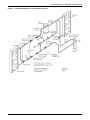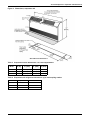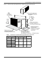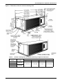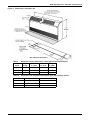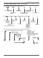
1
Precision Cooling
For Business-Critical Continuity™
Liebert® DataMate™–1.5 to 3 Tons (5 to 10.5kW) Capacity
Technical Data Manual– Air, Water/Glycol and Chilled Water Units, 50 & 60Hz
TABLE OF CONTENTS
1.0
INTRODUCTION . . . . . . . . . . . . . . . . . . . . . . . . . . . . . . . . . . . . . . . . . . . . . . . . . . . . . . . . . .1
1.1
Designed to Match Computer and Electronic Equipment Needs—From Installation
to Operation . . . . . . . . . . . . . . . . . . . . . . . . . . . . . . . . . . . . . . . . . . . . . . . . . . . . . . . . . . . . . . . . 1
2.0
STANDARD FEATURES—1.5- TO 3-TON SYSTEMS . . . . . . . . . . . . . . . . . . . . . . . . . . . . . . . .2
2.1
Evaporator Section—Split-Systems . . . . . . . . . . . . . . . . . . . . . . . . . . . . . . . . . . . . . . . . . . . . . 2
2.2
Condensing Unit Section—Remote Split-Systems . . . . . . . . . . . . . . . . . . . . . . . . . . . . . . . . . . 2
2.2.1
2.2.2
2.2.3
Indoor Centrifugal Fan Condensing Units . . . . . . . . . . . . . . . . . . . . . . . . . . . . . . . . . . . . . . . . . 2
Outdoor Prop Fan Condensing Units . . . . . . . . . . . . . . . . . . . . . . . . . . . . . . . . . . . . . . . . . . . . . 2
Indoor Remote Water/Glycol Condensing Units . . . . . . . . . . . . . . . . . . . . . . . . . . . . . . . . . . . . . 2
2.3
Condensing Unit Section—Close-Coupled . . . . . . . . . . . . . . . . . . . . . . . . . . . . . . . . . . . . . . . . 2
2.4
Chilled Water Units . . . . . . . . . . . . . . . . . . . . . . . . . . . . . . . . . . . . . . . . . . . . . . . . . . . . . . . . . . 2
2.5
System Controls . . . . . . . . . . . . . . . . . . . . . . . . . . . . . . . . . . . . . . . . . . . . . . . . . . . . . . . . . . . . . 3
2.5.1
Other Standard Control Features . . . . . . . . . . . . . . . . . . . . . . . . . . . . . . . . . . . . . . . . . . . . . . . . 3
3.0
OPTIONAL FACTORY-INSTALLED FEATURES—EVAPORATOR/CHILLED WATER &
CONDENSING UNITS . . . . . . . . . . . . . . . . . . . . . . . . . . . . . . . . . . . . . . . . . . . . . . . . . . . . . .4
3.1
Electric Reheat . . . . . . . . . . . . . . . . . . . . . . . . . . . . . . . . . . . . . . . . . . . . . . . . . . . . . . . . . . . . . . 4
3.2
Humidifier/Electric Reheat Package . . . . . . . . . . . . . . . . . . . . . . . . . . . . . . . . . . . . . . . . . . . . . 4
3.3
Optional Configurations—Prop Fan Condensing Units. . . . . . . . . . . . . . . . . . . . . . . . . . . . . . 4
3.4
Optional Configurations—Indoor Remote Water/Glycol Condensing Units . . . . . . . . . . . . . . 4
4.0
SHIP-LOOSE ACCESSORIES—FIELD-INSTALLED . . . . . . . . . . . . . . . . . . . . . . . . . . . . . . . . .5
4.1
Remote Monitoring, Autochangeover and Leak Detection Equipment . . . . . . . . . . . . . . . . . . 6
5.0
FLEXIBLE CONFIGURATIONS . . . . . . . . . . . . . . . . . . . . . . . . . . . . . . . . . . . . . . . . . . . . . . . .7
6.0
AIR-COOLED SYSTEMS—CAPACITIES AND DIMENSIONS . . . . . . . . . . . . . . . . . . . . . . . . . . .8
7.0
WATER/GLYCOLSYSTEMS—CAPACITIES AND DIMENSIONS . . . . . . . . . . . . . . . . . . . . . . . .14
8.0
CHILLED WATER SYSTEMS . . . . . . . . . . . . . . . . . . . . . . . . . . . . . . . . . . . . . . . . . . . . . . . . 20
9.0
ELECTRICAL DATA—ALL UNITS . . . . . . . . . . . . . . . . . . . . . . . . . . . . . . . . . . . . . . . . . . . . 23
10.0
REFRIGERANT PIPING . . . . . . . . . . . . . . . . . . . . . . . . . . . . . . . . . . . . . . . . . . . . . . . . . . . . 26
11.0
GLYCOL LOOP PIPING . . . . . . . . . . . . . . . . . . . . . . . . . . . . . . . . . . . . . . . . . . . . . . . . . . . 28
12.0
MODEL NUMBER NOMENCLATURE—ALL SYSTEMS . . . . . . . . . . . . . . . . . . . . . . . . . . . . . . 29
GUIDE SPECIFICATIONS—FOR LIEBERT DATAMATE 1.5- TO 3-TON (5 TO 10.5KW). . . . . . . . . . . . 31
1.0
2.0
3.0
GENERAL . . . . . . . . . . . . . . . . . . . . . . . . . . . . . . . . . . . . . . . . . . . . . . . . . . . . . . . . . . . . . . . . . . 31
PRODUCT . . . . . . . . . . . . . . . . . . . . . . . . . . . . . . . . . . . . . . . . . . . . . . . . . . . . . . . . . . . . . . . . . . 31
EXECUTION . . . . . . . . . . . . . . . . . . . . . . . . . . . . . . . . . . . . . . . . . . . . . . . . . . . . . . . . . . . . . . . . . 36
i
FIGURES
Figure 1
Figure 2
Figure 3
Figure 4
Figure 5
Figure 6
Figure 7
Figure 8
Figure 9
Figure 10
Figure 11
Figure 12
Figure 13
Figure 14
Figure 15
Figure 16
Figure 17
Figure 18
Figure 19
Figure 20
Figure 21
Figure 22
Wall-box . . . . . . . . . . . . . . . . . . . . . . . . . . . . . . . . . . . . . . . . . . . . . . . . . . . . . . . . . . . . . . . . . . . . . . . . 3
Flexible configurations—All systems. . . . . . . . . . . . . . . . . . . . . . . . . . . . . . . . . . . . . . . . . . . . . . . . . 7
General arrangement, air-cooled split systems. . . . . . . . . . . . . . . . . . . . . . . . . . . . . . . . . . . . . . . . 10
Dimensions, evaporator unit . . . . . . . . . . . . . . . . . . . . . . . . . . . . . . . . . . . . . . . . . . . . . . . . . . . . . . 11
Cabinet and floor planning dimensions—Outdoor air-cooled condensing units . . . . . . . . . . . . . . 12
Dimensions, indoor air-cooled condensing units . . . . . . . . . . . . . . . . . . . . . . . . . . . . . . . . . . . . . . . 13
General arrangement, water/glycol, split systems . . . . . . . . . . . . . . . . . . . . . . . . . . . . . . . . . . . . . 16
General arrangement, water/glycol systems, close-coupled condensing unit . . . . . . . . . . . . . . . . 16
Dimensions, evaporator unit . . . . . . . . . . . . . . . . . . . . . . . . . . . . . . . . . . . . . . . . . . . . . . . . . . . . . . 17
Dimensions, close-coupled water/glycol condensing unit . . . . . . . . . . . . . . . . . . . . . . . . . . . . . . . . 18
Cabinet dimensions and piping data, water/glycol indoor remote condensing modules. . . . . . . . 19
General arrangement—Chilled water systems . . . . . . . . . . . . . . . . . . . . . . . . . . . . . . . . . . . . . . . . 21
Dimensions—Chilled water unit . . . . . . . . . . . . . . . . . . . . . . . . . . . . . . . . . . . . . . . . . . . . . . . . . . . 22
Stepdown transformer for 277V input power applications. . . . . . . . . . . . . . . . . . . . . . . . . . . . . . . 25
Refrigerant piping diagram . . . . . . . . . . . . . . . . . . . . . . . . . . . . . . . . . . . . . . . . . . . . . . . . . . . . . . . 27
Heat rejection loop, multiple drycoolers and multiple indoor units. . . . . . . . . . . . . . . . . . . . . . . . 28
Model number nomenclature—Evaporator units . . . . . . . . . . . . . . . . . . . . . . . . . . . . . . . . . . . . . . 29
Model number nomenclature—Outdoor air-cooled condensing units . . . . . . . . . . . . . . . . . . . . . . 29
Model number nomenclature—Indoor air-cooled condensing units. . . . . . . . . . . . . . . . . . . . . . . . 29
Model number nomenclature, close-coupled water/glycol condensing units—60Hz only . . . . . . . 30
Model number nomenclature—Indoor remote water/glycol-cooled condensing units. . . . . . . . . . 30
Model number nomenclature—Chilled water units . . . . . . . . . . . . . . . . . . . . . . . . . . . . . . . . . . . . 30
ii
TABLES
Table 1
Table 2
Table 3
Table 4
Table 5
Table 6
Table 7
Table 8
Table 9
Table 10
Table 11
Table 12
Table 13
Table 14
Table 15
Table 16
Table 17
Table 18
Table 19
Table 20
Table 21
Table 22
Table 23
Table 24
Table 25
Table 26
60Hz capacities & typical specifications, air-cooled applications. . . . . . . . . . . . . . . . . . . . . . . . . . . 8
50Hz capacities & typical specifications, air-cooled applications. . . . . . . . . . . . . . . . . . . . . . . . . . . 9
Evaporator section dimensions—air-cooled applications . . . . . . . . . . . . . . . . . . . . . . . . . . . . . . . . 11
Evaporator unit refrigerant connections—pipe size/coupling number . . . . . . . . . . . . . . . . . . . . . 11
Propeller fan, air-cooled condensing unit dimensions, inches (mm) . . . . . . . . . . . . . . . . . . . . . . . 12
Remote centrifugal fan, air-cooled condensing, weight and dimensions . . . . . . . . . . . . . . . . . . . . 13
60Hz capacities & typical specifications, water-cooled and glycol-cooled applications. . . . . . . . . 14
50Hz capacities & typical specifications, water-cooled and glycol-cooled applications. . . . . . . . . 15
Evaporator section dimensions—water/ glycol-cooled applications . . . . . . . . . . . . . . . . . . . . . . . . 17
Evaporator unit refrigerant connections—pipe size/coupling number . . . . . . . . . . . . . . . . . . . . . 17
Net weight, water/glycol condensing units . . . . . . . . . . . . . . . . . . . . . . . . . . . . . . . . . . . . . . . . . . . 18
Net weight, indoor water/glycol-cooled condensing unit. . . . . . . . . . . . . . . . . . . . . . . . . . . . . . . . . 19
Chilled water data, 50/60Hz. . . . . . . . . . . . . . . . . . . . . . . . . . . . . . . . . . . . . . . . . . . . . . . . . . . . . . . 20
Chilled water capacity correction factors based on 10°F (5.6°C) water rise . . . . . . . . . . . . . . . . . 21
Net weights and dimensions, chilled water units . . . . . . . . . . . . . . . . . . . . . . . . . . . . . . . . . . . . . . 22
Electrical data, split system evaporator or chilled water unit, 60/50Hz . . . . . . . . . . . . . . . . . . . . 23
60Hz electrical data, evaporator with close-coupled water/glycol condensing unit with
common power feed . . . . . . . . . . . . . . . . . . . . . . . . . . . . . . . . . . . . . . . . . . . . . . . . . . . . . . . . . . . . . . 23
60Hz electrical data, outdoor air-cooled condensing unit . . . . . . . . . . . . . . . . . . . . . . . . . . . . . . . . 24
50Hz electrical data, outdoor air-cooled condensing unit . . . . . . . . . . . . . . . . . . . . . . . . . . . . . . . . 24
Electrical data, indoor air & water/glycol remote condensing units, 50 & 60Hz . . . . . . . . . . . . . 25
Refrigerant charge . . . . . . . . . . . . . . . . . . . . . . . . . . . . . . . . . . . . . . . . . . . . . . . . . . . . . . . . . . . . . . 26
Recommended refrigerant line sizes . . . . . . . . . . . . . . . . . . . . . . . . . . . . . . . . . . . . . . . . . . . . . . . . 26
Pipe length and condenser elevation relative to evaporator . . . . . . . . . . . . . . . . . . . . . . . . . . . . . 26
Refrigerant charge in Liebert pre-charged R-407C line sets . . . . . . . . . . . . . . . . . . . . . . . . . . . . . 26
Line charges - refrigerant per 100 ft. (30m) of Type L copper tube . . . . . . . . . . . . . . . . . . . . . . . . 27
Equivalent lengths for various pipe fittings, ft (m). . . . . . . . . . . . . . . . . . . . . . . . . . . . . . . . . . . . . 27
iii
iv
Introduction
1.0
INTRODUCTION
1.1
Designed to Match Computer and Electronic Equipment Needs—From Installation
to Operation
Installed on the floor or on the wall, Liebert DataMate Precision Cooling systems control the cooling,
humidity and air distribution required by sensitive electronic equipment. A range of sizes and configurations is available to meet varying sites’ needs.
The Liebert DataMate is also easy to use. Advanced microprocessor technology allows easy, precise
control and menu-driven monitoring keeps you informed of system operation through the LCD readout.
These features, combined with Emerson quality construction and reliable components, guarantee satisfaction from installation through operation.
Liebert Precision Cooling
Liebert Precision Cooling systems are designed to control the environment required for computers
and other sensitive electronic equipment. The Liebert DataMate provides complete control on an
around-the-clock basis and the high sensible heat ratio required by sensitive electronic equipment.
Easy Installation
The Liebert DataMate is a split-system evaporator combined with a remote air-, water- or glycolcooled condensing unit or a close-coupled water/glycol-cooled condensing unit or is a self-contained,
chilled water unit.
Each split system has thermostat-type wiring to controls and condensing unit. System components
are pre-charged with refrigerant using quick-connect fittings and can be easily connected together.
Optional pre-charged line sets or sweat adapters for field refrigerant piping are available for remote
condensing units.
Easy to Service
The Liebert DataMate is designed for front service access. Routine maintenance and service can be
performed quickly and easily. Spare parts are always in Emerson inventory and available on short
notice.
Advanced Control Technology
A menu-driven microprocessor control system provides precise temperature and humidity control and
accurate alarm setpoints. Using touch-sensitive buttons, the wall-mounted monitor/control panel
allows you to select and display temperature and other monitored parameters.
High Efficiency
High sensible heat ratio, scroll compressor and precise microprocessor control allow the system to
operate efficiently.
Space Saving Design
Models available to fit any room without disrupting workstation layout. Requires 5 ft2 (0.5m2) or less
of floor space or can be mounted on a wall.
Reliable
The Liebert DataMate installed base is a testimony to the system reliability.
Agency Listed
Standard 60Hz units are CSA certified to the harmonized U.S. and Canadian
product safety standard, CSA C22.2 No 236/UL 1995 for “Heating and Cooling
Equipment” and are marked with the CSA c-us logo. The units are also MEA
listed for New York City applications.
C
1
US
Standard Features—1.5- to 3-Ton Systems
2.0
STANDARD FEATURES—1.5- TO 3-TON SYSTEMS
2.1
Evaporator Section—Split-Systems
The Liebert DataMate is available as a split system air, water/glycol-cooled unit or self-contained
chilled water unit.
Split-System Evaporator Section includes the evaporator coil, 2-speed centrifugal blower assembly, filter-drier, galvanized steel drain pan, R-407C refrigerant charge, cleanable filters and microprocessor control with wall-mounted display panel. The unit construction is galvanized steel with
powder-coated, removable exterior panels. A reversible discharge grille provides the ability to redirect
airflow. The evaporator can be floor- or wall-mounted.
2.2
Condensing Unit Section—Remote Split-Systems
2.2.1
Indoor Centrifugal Fan Condensing Units
Indoor Air-Cooled Centrifugal Fan Condensing Units include scroll compressor, factory-mounted disconnect switch, condenser coil, R-407C unit charge, belt-driven centrifugal blower assembly, highpressure switch, Liebert Lee-Temp head pressure control system, hot gas bypass and liquid-line solenoid valve. Unit must be mounted indoors. Condensing unit is designed to use outdoor air with temperatures ranging from -30°F to 95°F (-34°C to 35°C). Available in 2- & 3-Ton models.
2.2.2
Outdoor Prop Fan Condensing Units
Outdoor Prop Fan Condensing Units include scroll compressor, condenser coil, R-407C unit charge,
prop fan, liquid-line solenoid valve, high pressure switch, Liebert Lee-Temp head pressure control
and hot gas bypass. Condensing unit is designed for outdoor locations with operating ambients ranging from -30°F to 95°F (-34°C to 35°C).
2.2.3
Indoor Remote Water/Glycol Condensing Units
Indoor Remote Water/Glycol Condensing Units include scroll compressor, R-407C unit charge, factory-mounted disconnect, coaxial condenser, hot gas bypass, high head pressure switch and two-way
water regulating valve designed for 150psi (1034.3kPa). Condensing units can be used on either a
water or glycol cooling loop. Available in 2- and 3-ton models.
2.3
Condensing Unit Section—Close-Coupled
The Close-Coupled Water/Glycol Condensing Unit is designed to attach to the split-system evaporator to become a single wall- or floor-mounted unit.
Indoor close-coupled water/glycol condensing units include reciprocating compressor, brazed plate
condenser, R-407C refrigerant charge and 2-way water regulating valve. Unit is available in 60Hz
models only. Design pressure is 150psi (1034kPa).
2.4
Chilled Water Units
Self-Contained Chilled Water Models include a chilled water coil, a two-way, solenoid open, slowclose (On/Off) spring-return valve, two-speed centrifugal blower assembly, cleanable filters and
microprocessor control with wall-mounted display panel. Design pressure is 125psi (862kPa).
2
Standard Features—1.5- to 3-Ton Systems
2.5
System Controls
System controls include a microprocessor control board mounted in the evaporator/chilled water unit
and a wall-mounted interface with a two-line, 16-character liquid crystal display. An eight-key, membrane keypad for setpoint/program control, unit On/Off, fan speed and alarm silence is below the LCD
screen. It provides temperature setpoint and sensitivity adjustment, humidity setpoint and sensitivity adjustment, digital display of temperature, humidity, setpoints, sensitivities, fan speed and alarm
conditions.
The wall-box is field-wired to the microprocessor control using standard four-conductor thermostat
wire (field-supplied). The temperature and humidity sensors are in the wall box, which can be
installed up to 300 feet (91.4m) from the evaporator unit. The unit-mounted control board also
includes common alarm terminals and shutdown terminals. The unit automatically restarts after a
power outage.
Figure 1
2.5.1
Wall-box
Other Standard Control Features
• Adjustable auto restart
• Calibrate sensors
• 5 day/2 day setback
• Predictive humidity control
• Password protection
• Common alarm output
• Alarm enable/disable
• Remote shutdown terminals
• Self-diagnostics
3
Optional Factory-Installed Features—Evaporator/Chilled Water & Condensing Units
3.0
OPTIONAL FACTORY-INSTALLED FEATURES—EVAPORATOR/CHILLED WATER &
CONDENSING UNITS
3.1
Electric Reheat
Electric low watt tubular reheat element with non-corrosive metal sheath provides one stage of nonionizing reheat to maintain room dry bulb temperature.
3.2
Humidifier/Electric Reheat Package
The humidifier and electric reheat are available as a package for complete humidity control. The canister humidifier includes a steam-generating type humidifier with automatic flushing circuit, inlet
strainer, drain, 1" (25.4mm) air gap on fill line and solenoid valves. Humidifier problem alarm annunciates at the wall-mounted display panel. Maximum humidifier water supply pressure is 150psi
(1034kPa).
3.3
Optional Configurations—Prop Fan Condensing Units
Outdoor Prop Fan Condensing Units are also available in the following optional configurations:
• High ambient models for providing catalog capacities at ambient temperatures up to 105°F (40°C)
- 2- and 3-ton models only.
• Quiet-Line models for low noise level conditions (below 56 dBA) and for providing catalog capacities at ambient temperatures up to 95°F (35°C) - 2- and 3-ton models only.
• Condenser coils can be phenolic-coated for extended coil life in coastal areas.
3.4
Optional Configurations—Indoor Remote Water/Glycol Condensing Units
Indoor Remote Water/Glycol Condensing Units are also available with the following piping options:
• Two-way water regulating valve with 350psi (2413kPa) design pressure.
• Three-way water regulating valve with 150psi (1034kPa) design pressure.
• Three-way water regulating valve with 350psi (2413kPa) design pressure.
4
Ship-Loose Accessories—Field-Installed
4.0
SHIP-LOOSE ACCESSORIES—FIELD-INSTALLED
The Condensate Pump is field-mounted internal to the unit and wired to the unit power block or is
field-mounted external to the unit with power from unit or external power supply. Pump is complete
with integral float switch, discharge check valve, pump, motor assembly and reservoir. A secondary
float can be field-wired to shut down the unit upon high condensate level.
The Canister Humidifier Kit can be field-installed to customize cooling only or reheat only units.
The kit includes full installation instructions and are designed to be added to the evaporator unit
before it is mounted on its wall or floor location.
The 277V Step-Down Transformer is available for units needing 277-1-60 input power; one each
for evaporator section and remote condensing section (37.5A max. each). Use one 37.5A transformer
for 1-1/2 or 2-ton self-contained water/glycol systems; use 50A transformer for 3-ton self-contained
water/glycol systems. Epoxy-encapsulated, transformer is suitable for either indoor or outdoor service.
Pre-Charged Refrigerant Line Set (R-407C) contains an insulated copper suction line and a copper liquid line for interconnection of the indoor and outdoor sections. Available in 15-foot (4.5m) and
30-foot (9m) sections for interconnection of evaporator to remote condensing unit without brazing.
Maximum recommended combined line set length is 45 ft.(13.7m).
The Refrigerant-Line Sweat Adapter Kit contains two suction and two liquid line fittings that
allow field-supplied refrigerant piping between the evaporator and condensing unit.
A Remote Temperature and Humidity Sensor package includes sensors in an attractive case
with 30 ft. (9 m) of cable. Can be wall or duct mounted. Remote sensors should be used when the wall
box is not located in the space to be conditioned.
NOTE
Installing the remote sensors disables the sensors included in the wall box.
5
Ship-Loose Accessories—Field-Installed
4.1
Remote Monitoring, Autochangeover and Leak Detection Equipment
The Liebert RCM4™ is a four-point, normally open, dry contact monitoring panel. One Form-C, dry
contact common alarm relay output (rated at 24 VAC, 3 Amp) is provided. Four red LEDs illuminate
on the respective alarm and the alarm buzzer is silenced by a front panel switch. The RCM4 requires
a 24VAC or 24VDC power source. Power supply is not included.
The Liebert AC4™ Autochangeover Controller provides autochangeover and autosequence control for up to four Liebert DataMate units within a room. The Liebert AC4 will enable redundant
units in an alarm condition, balance usage and test standby units at programmed intervals. Two common alarm relay outputs are available. A built-in LCD and RS-232 port for direct PC/terminal connection provides two options for configuration and monitoring of the product. The Liebert AC4 requires
24VAC input power.
The Liebert AC8™ is ideal for coordinated control of systems with redundant units. The Liebert AC8
enables redundant devices during an alarm condition, balances usage of devices and tests standby
devices at programmable intervals. Supports four zones and can use the 4-20mA temperature sensor
(TW420) for temperature staging in each zone. Two programmable output control relays are available
for auxiliary control such as humidity lockout. Emergency power operation input provided for device
control during an emergency. Two common alarm relay outputs are available. A built-in LCD and
RS-232 port for direct PC/terminal connection provides two options for configuration and monitoring
of the product.
The Liebert ENV-DO™ interface card provides 16 discrete outputs, corresponding to status and
major alarm conditions of Environmental units. The Liebert ENV-DO-ENCL1 packages one Environmental DO interface card in its own steel enclosure and the ENV-DO-ENCL2 packages two Environmental DO interface cards in one enclosure for installation external to the Liebert DataMate. The
self-contained kit includes an external 120VAC-to-24VAC power transformer. Wiring harnesses are
not provided. Power and communication wiring is field-provided.
The Liebert Liqui-tect® 410 Point Leak Detection Sensor detects the presence of conductive liquid using a pair of corrosion-resistant, gold-plated probes mounted in a painted, height-adjustable
enclosure. Dual Form-C, dry contact common alarm relays (rated at 24VAC, 3A) signal a leak
detected as well as loss of power and cable fault. The Liebert Liqui-tect 410 requires an external
24VAC or 24VDC power source.
Liebert LT460 Zone Leak Detection Kits include one LT460 sensor, a specified length of LT500xxY cable (maximum length is 100 ft [30.5m]) and a corresponding number of hold-down clips. The
Liebert LT460 requires an external 24VAC, 0.12A power source, such as EXT-XFMR or XFMR24.
Liebert SiteScan® is a monitoring solution that gives you decision-making power to effectively manage the equipment critical to your business.
Liebert SiteScan enables communication from Liebert environmental and power units, as well as
many other pieces of analog or digital equipment, to a front-end software package that provides
real-time status and alarms so you can react quickly to changing situations.
Liebert SiteScan is designed with flexibility for both small systems and large, complex systems such
as those in computer rooms, telecommunications facilities or industrial process control rooms. Contact your local Emerson representative for assistance with a Liebert SiteScan system.
6
Flexible Configurations
5.0
FLEXIBLE CONFIGURATIONS
Figure 2
Flexible configurations—All systems
Air-Cooled Systems
L ie be
rt
¨
¨
Liebert
OUTDOOR, AIR-COOLED CONDENSING UNIT
Suitable for installation on a roof or at ground
level.
INDOOR AIR-COOLED CONDENSING UNIT
For applications where roof or ground level
locations are impractical.
Water/Glycol-Cooled Systems
L ie be
¨
Liebert
WATER/GLYCOL-COOLED CLOSE-COUPLED
A single power and water supply
connection puts the unit in operation.
rt
¨
WATER/GLYCOL-COOLED REMOTE
Condensing unit is installed under
raised floor or above dropped ceiling.
Chilled Water Systems
¨
Liebert
CHILLED WATER
Connects to a chilled water loop
for quick and easy installation.
7
Air-Cooled Systems—Capacities and Dimensions
6.0
Table 1
AIR-COOLED SYSTEMS—CAPACITIES AND DIMENSIONS
60Hz capacities & typical specifications, air-cooled applications
Evaporator Model
DME020E
PFH - Outdoor
DME027E
DME037E
Condensing Unit Type
DX Evaporator- Net Capacity Data - kW (Btuh) @ High Speed CFM
80°F DB, 62.8°F WB
Total 5.40 (18,500)
7.10 (24,200)
(26.7°C DB, 17.1°C
Sensible 5.40 (18,500)
7.10 (24,200)
WB) 38 %RH
75°F DB, 61°F WB
Total 5.05 (17,200)
6.60 (22,500)
(23.9°C DB, 16.1°C
Sensible 4.90 (16,700)
6.50 (22,200)
WB) 45 %RH
MCD - Indoor
PFH - Outdoor
MCD - Indoor
6.85 (23,300)
10.1 (34,600)
9.60 (32,700)
6.85 (23,300)
9.70 (33,100)
9.40 (32,000)
6.35 (21,700)
9.75 (33,200)
9.15 (31,300)
6.35 (21,600)
8.60 (29,400)
8.35 (28,500)
Total
72°F DB, 60°F WB
(22.2°C DB, 15.5°C
Sensible
WB) 50 %RH
Fan Data - Evaporator
CFM (CMH) - High Speed
CFM (CMH) - Low Speed
PFH - Outdoor
4.85 (16,500)
6.35 (21,700)
6.10 (20,800)
9.50 (32,400)
8.95 (30,600)
4.50 (15,400)
6.05 (20,600)
5.90 (20,100)
7.95 (27,100)
7.70 (26,200)
870 (1478)
1230 (2090)
750 (1274)
1050 (1784)
1320 (2243)
1175(1996)
Fan Motor hp (W)
0.16 (120)
0.20 (150)*
0.27 (200)**
Evaporator Coil - Copper Tube/Aluminum Fin
2.44 (0.23)
3.92 (0.36)
Face Area ft2 (m2)
3.92 (0.36)
Coil Rows
4
3
4
Max Face Velocity-fpm (m/s)
356 (1.8)
313 (1.6)
336 (1.7)
Unit Refrigerant Charge, oz. (kg)
4 (0.11)
5 (0.14)
6.5 (0.18)
Unit Operating Weight, lb. (kg)
230 (104)
330 (150)
365 (165)
Electric Reheat Capacities (Includes Fan Motor)-kW (Btuh)
Input Voltage 230-1-60
2.7 (9215)
5.3 (18080)
5.5 (18765)
Humidifier Data - Steam Generator Type
Steam capacity - lbs/hr (kg/hr)
3 (1.4)
3 (1.4)
3 (1.4)
Electrical Input Power - kW
1
1
1
Evaporator Connection Sizes
Liquid line Diameter - Aeroquip
3/8"
3/8"
3/8"
Coupling Size, - #6 Female
Suction Line Diameter - Aeroquip
1/2"
7/8"
7/8"
Coupling Size, #11 Female
Humidfier Supply,
1/4"
1/4"
1/4"
OD Cu Compression Fitting
Humidifier Drain, Barb Fitting
1/2"
1/2"
1/2"
Evaporator Drain
3/4" OD
3/4" OD
3/4" OD
Filter
Washable Polypropylene/Aluminum
PFH020A-_L7
PFH027A-_L7 MCD24AL_H7 PFH037A-_L7 MCD36AL_H7
Condensing Unit Model Number
Condensing Unit Rating Conditions
Coil Face Area ft2 (m2)
Rows of Coil
CFM (CMH)
Motor, hp (W)
External Static Pressure, in wg.
(mm)
Condensing Unit Refrigerant
Charge, oz. (kg)
Unit Operating Weight, lb. (kg)
4.1 (0.38)
2
2200 (3738)
0.20 (149)
95°F (35°C) Ambient
4.1 (0.38)
4.6 (0.43)
7.7 (0.72)
2
4
2
2200 (3738)
1000 (1699)
3000 (5097)
0.20 (149)
0.33 (246)
0.20 (149)
N/A
N/A
0.50 (13)
N/A
4.6 (0.43)
4
1430 (2490)
0.5 (373)
0.50 (13)
134 (3.8)
134 (3.8)
134 (3.8)
213 (6.0)
213 (6.0)
200 (91)
351 (159)
449 (204)
351 (159)
449 (204)
The net capacity data has fan motor heat factored in for all ratings and the entering air conditions of 75°F (23.9 °C), 45%RH, is the standard
rating condition for ASHRAE 127-2007. All capacities are nominal values; actual performance will be ± 5%.
* DME027 has two motors - 0.08 & 0.12 HP
** DME037 has two motors - 0.11 & 0.16 HP
8
Air-Cooled Systems—Capacities and Dimensions
Table 2
50Hz capacities & typical specifications, air-cooled applications
DME020E
Evaporator Model
DME027E
DME037E
PFH - Outdoor PFH - Outdoor MCD - Indoor PFH - Outdoor MCD - Indoor
Condensing Unit Type
DX Evaporator- Net Capacity Data - kW (Btuh) @ High Speed CFM
Total 5.15 (17,500)
80°F DB, 62.8°F WB (26.7°C
DB, 17.1°C WB) 38 %RH Sensible 5.05 (17,200)
6.50 (22,200)
6.40 (21,800)
9.90 (33,800)
9.45 (32,300)
6.50 (22,200)
6.40 (21,800)
8.85 (30,200)
8.65 (29,500)
Total 4.80 (16,400)
75°F DB, 61°F WB (23.9°C
DB, 16.1°C WB) 45 %RH Sensible 4.50 (15,300)
6.15 (20,900)
6.00 (20,500)
9.55 (32,500)
9.10 (31,100)
5.90 (20,100)
5.80 (19,800)
7.90 (26,900)
7.70 (26,300)
Total 4.65 (15,900)
5.95 (20,300)
5.80 (19,800)
9.30 (31,800)
8.90 (30,400)
5.40 (18,500)
5.35 (18,300)
7.30 (24,900)
7.10 (24,300)
72°F DB, 60°F WB (22.2°C
DB, 15.5°C WB) 50 %RH Sensible 4.10 (14,000)
Fan Data - Evaporator
CFM (CMH) - High Speed
725 (1232)
1025 (1741)
1100 (1869)
CFM (CMH) - Low Speed
625 (1062)
875 (1487)
980 (1665)
Fan Motor HP (W)
0.16 (120)
0.20 (150)*
0.27 (200)**
2.44 (0.23)
3.92 (0.36)
3.92 (0.36)
4
3
4
Max Face Velocity-fpm (m/s)
356 (1.8)
313 (1.6)
336 (1.7)
Unit Refrigerant Charge, oz. (kg)
4 (0.11)
5 (0.14)
6.5 (0.18)
230 (104)
330 (150)
365 (165)
5.3 (18080)
5.5 (18765)
3 (1.4)
3 (1.4)
3 (1.4)
1
1
1
Liquid line Diameter - Aeroquip
Coupling Size, #6 Female
3/8"
3/8"
3/8"
Suction Line Diameter - Aeroquip
Coupling Size, - #11 Female
1/2"
7/8"
7/8"
Humidfier Supply,
OD Cu Compression Fitting
1/4"
1/4"
1/4"
Humidifier Drain, Barb Fitting
1/2"
1/2"
1/2"
Evaporator Drain, OD
3/4"
3/4"
3/4"
Evaporator Coil - Copper Tube/Aluminum Fin
Face Area ft2 (m2)
Coil Rows
Unit Operating Weight, lb. (kg)
Electric Reheat Capacities (Includes Fan Motor)-kW (Btuh)
Input Voltage 230-1-50
2.7 (9215)
Humidifier Data - Steam Generator Type
Steam capacity - lb/hr (kg/hr)
Electrical Input Power - kW
Evaporator Connection Sizes
Filter
Condensing Unit Model Number
Washable Polypropylene/Aluminum
PFH019A-_L7 PFH026A-_L7 MCD23AL_H7
Condensing Unit Rating Conditions
Coil Face Area ft2 (m2)
PFH036A-_L7 MCD35AL_H7
95°F (35°C) Ambient
4.1 (0.38)
4.1 (0.38)
4.6 (0.43)
7.7 (0.72)
4.6 (0.43)
Rows of Coil
2
2
4
2
4
CFM (CMH)
1800 (3058)
1800 (3058)
1000 (1699)
2500 (4248)
1430 (2430)
0.20 (149)
0.20 (149)
0.33 (246)
0.20 (149)
0.5 (373)
External Static Pressure, in wg. (mm)
N/A
N/A
0.50 (13)
N/A
0.50 (13)
Condensing Unit Refrigerant Charge,
oz. (kg)
134 (3.8)
134 (3.8)
134 (3.8)
213 (6.0)
213 (6.0)
Unit Operating Weight, lb. (kg)
200 (91)
351 (159)
449 (204)
351 (159)
449 (204)
Motor Hp (W)
The net capacity data has fan motor heat factored in for all ratings and the entering air conditions of 75°F (23.9 °C), 45%RH, is the standard
rating condition for ASHRAE 127-2007. All capacities are nominal values; actual performance will be ± 5%.
* DME027 has two motors - 0.08 & 0.12 HP
** DME037 has two motors - 0.11 & 0.16 HP
9
Air-Cooled Systems—Capacities and Dimensions
Figure 3
General arrangement, air-cooled split systems
10
Air-Cooled Systems—Capacities and Dimensions
Figure 4
Dimensions, evaporator unit
See Table 3 for Dimension A
Table 3 Evaporator section dimensions—air-cooled applications
Model
Weight
lb (kg)
Width - A
in. (mm)
Depth
in. (mm)
Height
in. (mm)
DME020E
230 (104) 46-1/2 (1181) 11-7/8 (302)
32 (813)
DME027E
330 (150) 64-1/8 (1628) 11-7/8 (302)
32 (813)
DME037E
365 (165) 64-1/8 (1628) 11-7/8 (302)
32 (813)
Table 4 Evaporator unit refrigerant connections—pipe size/coupling number
Model
Liquid Line A
Suction Line B
DME020E
3/8" / #6
1/2" / #11
DME027E
3/8" / #6
7/8" / #11
DME037E
3/8" / #6
7/8" / #11
11
Air-Cooled Systems—Capacities and Dimensions
Figure 5
Cabinet and floor planning dimensions—Outdoor air-cooled condensing units
Removable (right) panel
for access to refrigeration
component
Fan Rotation
CCW (left side)
A
Right Air
Discharge
Left Air
Intake
B
Shaded area indicates
a minimum clearance of
18" (457mm) for proper airflow
Shaded area indicates
a recommended
clearance of 24" (610mm)
for component access
and removal
C
Shaded area indicates
a minimum clearance of
18" (457mm) for proper airflow
Table 5
Removable panel for
access to high voltage &
low voltage connections,
and refrigeration components
DPN000130_Rev0
Propeller fan, air-cooled condensing unit dimensions, inches (mm)
Model Numbers
60Hz
50Hz
PFH020A-L
PFH019A-L
PFH027A-L
PFH026A-L
PFH027A-H
PFH026A-H
PFHZ27A-L
PFHZ26A-L
PFH037A-L
PFH036A-L
PFH037A-H
PFH036A-H
PFHZ37A-L
PFHZ36A-L
Dimensional Data, inches (mm)
A
B
C
Module Net
Weight
lb (kg)
40 (1016)
23 1/2 (597)
18 (457)
200 (91)
48 (1219)
31 (787)
18 (457)
241 (109)
53 (1343)
36 1/4 (918)
18 (457)
351 (159)
12
Air-Cooled Systems—Capacities and Dimensions
Figure 6
Dimensions, indoor air-cooled condensing units
Table 6
Model
MC*23A
MC*24A
MC*35A
MC*36A
Remote centrifugal fan, air-cooled condensing, weight and dimensions
Weight
lb (kg)
Dimensions, in (mm)
A
B
C
D
1-7/16 (37)
11-7/16 (290)
1/2 (13)
20-7/16 (519)
230 (104)
240 (109)
13
Water/GlycolSystems—Capacities and Dimensions
7.0
Table 7
WATER/GLYCOLSYSTEMS—CAPACITIES AND DIMENSIONS
60Hz capacities & typical specifications, water-cooled and glycol-cooled applications
DME020E
DME027E
DME037E
WaterGlycolWaterGlycolWaterGlycolCooled
Cooled
Cooled
Cooled
Cooled
Cooled
Condensing Unit Type
DX Evaporator- Net Capacity Data - kW (Btuh) @ High Speed CFM
Total 5.90 (20,100) 5.15 (17,600) 7.95 (27,200) 6.75 (23,000) 11.4 (38,900) 9.65 (32,900)
80°F DB, 62.8°F WB (26.7°C DB,
17.1°C WB) 38 %RH
Sensible 5.80 (19,800) 5.15 (17,600) 7.90 (27,000) 6.75 (23,000) 10.3 (35,300) 9.40 (32,100)
Total 5.50 (18,800) 4.80 (16,300) 7.55 (25,800) 6.25 (21,300) 11.0 (37,400) 9.20 (31,400)
75°F DB, 61°F WB (23.9°C DB,
16.1°C WB) 45 %RH
Sensible 5.15 (17,600) 4.75 (16,200) 7.10 (24,200) 6.25 (21,300) 9.20 (31,400) 8.35 (28,500)
Total 5.35 (18,100) 4.60 (15,700) 7.35 (25,000) 6.00 (20,500) 10.7 (36,600) 8.95 (30,600)
72°F DB, 60°F WB (22.2°C DB,
15.5°C WB) 50 %RH
Sensible 4.75 (16,200) 4.35 (14,900) 6.55 (22,300) 5.85 (19,900) 8.55 (29,100) 7.70 (26,300)
Fan Data - Evaporator
CFM (CMH) - High Speed
870 (1478)
1230 (2090)
1320 (2243)
CFM (CMH) - Low Speed
750 (1274)
1050 (1784)
1175(1996)
Fan Motor hp (W)
0.16 (120)
0.20 (150)*
0.27 (200)**
Evaporator Coil - Copper Tube/Aluminum Fin
2.44 (0.23)
3.92 (0.36)
3.92 (0.36)
Face Area ft2 (m2) 2.44 (0.23)
Coil Rows
4
3
4
Max Face Velocity-fpm (m/s)
356 (1.8)
313 (1.6)
336 (1.7)
Unit Refrigerant Charge, oz. (kg)
4 (0.11)
5 (0.14)
6.5 (0.18)
Unit Operating Weight, lb. (kg)
230 (104)
330 (150)
365 (165)
Electric Reheat Capacities (Includes Fan Motor)-kW (Btuh)
Input Voltage 230-1-60
2.7 (9215)
5.3 (18080)
5.5 (18765)
Humidifier Data - Steam Generator Type
Steam capacity - lbs/hr (kg/hr)
3 (1.4)
3 (1.4)
3 (1.4)
Electrical Input Power - kW
1
1
1
Evaporator Connection Sizes
Liquid line Diameter - Aeroquip Coupling Size, #6
3/8"
3/8"
3/8"
Female
Suction Line Diameter - Aeroquip Coupling Size,
1/2"
7/8"
7/8"
#11 Female
Humidfier Supply
1/4" OD Copper Compression Fitting
Humidifier Drain, Barb Fitting
1/2"
1/2"
1/2"
Evaporator Drain, OD
3/4"
3/4"
3/4"
Filter
Washable Polypropylene/Aluminum
DMC022WG
DMC029WG
DMC040WG
Close-Coupled DMC Condensing Unit Model
110 (43.3)
110 (43.3)
110 (43.3)
85 (29.4)
85 (29.4)
85 (29.4)
EGT - 40%
EGT - 40%
Condenser Fluid Requirements, °F (°C)
EGT - 40%
EWT
EWT
EWT
PG
PG
PG
THR - kW (Btuh) @ 75F/45%RH 7.30 (24,900) 7.10 (24,200) 9.60 (32,700) 9.10 (31,000) 13.9 (47,400) 13.2 (45,100)
Flow Rate - GPM (l/m) 4.0 (15.2)
5.9 (22.4)
4.6 (17.4)
6.9 (26.2)
7.8 (29.6)
9.1 (34.5)
17.0 (50.8)
4.4 (13.2)
10.4 (31.1)
8.4 (25.1)
13.6 (40.7)
Pressure Drop - ft. of H20 (kPa) 7.0 (20.9)
Water-Cooled Condensing Temperature, °F (°C) 105 (40.6 )
N/A
105 (40.6 )
N/A
105 (40.6 )
N/A
Connection Sizes, in. (mm) OD
5/8 (15.9)
7/8 (22.2)
Unit Volume - Gal (l)
0.25 (0.95)
0.40 (1.5)
0.50 (1.9)
Unit Refrigerant Charge, oz. (kg)
47 (1.33)
59 (1.67)
61 (1.72)
Unit Operating Weight, lb. (kg)
169 (77)
169 (77)
172 (78)
MCD26W
MCD38W
—
—
Remote MCD Condensing Unit Model #
110 (43.3)
110 (43.3)
85 (29.4)
85 (29.4)
EGT - 40 %
EGT - 40 %
Condenser Fluid Requirements, °F (°C)
N/A
EWT
EWT
PG
PG
THR - kW (Btuh) @ 75F/45%RH
—
—
9.60 (32,700) 9.10 (31,000) 13.9 (47,400) 13.2 (45,100)
Flow Rate - GPM (l/m)
—
—
7.7 (24.2)
8.9 (33.7)
6.5 (24.6)
12.1 (45.9)
—
—
16.6 (49.6)
26.0 (77.7)
11.6 (34.7)
44.7 (133.7)
Pressure Drop - ft. of H20 (kPa)
105°F
105°F
Water-Cooled Condensing Temperature
—
—
N/A
N/A
(40.6°C)
(40.6°C)
Connection Sizes, in. (mm) OD
—
—
7/8 (22.2)
7/8 (22.2)
Unit Volume - Gal (l)
—
—
1.2 (4.5)
1.2 (4.5)
Unit Refrigerant Charge, oz. (kg)
—
—
41 (1.16)
54 (1.54)
Unit Operating Weight, lb. (kg)
—
—
175 (79)
220 (100)
The net capacity data has fan motor heat factored in for all ratings and the entering air conditions of 75°F (23.9 °C), 45%RH, is the
standard rating condition for ASHRAE 127-2007. All capacities are nominal values; actual performance will be ± 5%.
* DME027 has two motors - 0.08 & 0.12 HP; ** DME037 has two motors - 0.11 & 0.16 HP
Evaporator Model
14
Water/GlycolSystems—Capacities and Dimensions
Table 8
50Hz capacities & typical specifications, water-cooled and glycol-cooled applications
DME027E
Evaporator Model
Water-Cooled
Condensing Unit Type
DME037E
Glycol-Cooled
Water-Cooled
Glycol-Cooled
11.3 (38,700)
9.30 (31,800)
DX Evaporator- Net Capacity Data - kW (Btuh) @ High Speed CFM
80°F DB, 62.8°F WB (26.7°C DB,
17.1°C WB) 38 %RH
75°F DB, 61°F WB (23.9°C DB,
16.1°C WB) 45 %RH
72°F DB, 60°F WB (22.2°C DB,
15.5°C WB) 50 %RH
Total
7.55 (25,700)
6.15 (21,000)
Sensible
7.20 (24,600)
6.15 (21,000)
9.55 (32,600)
8.60 (29,300)
Total
7.20 (24,500)
5.75 (19,600)
11.0 (37,400)
8.95 (30,500)
Sensible
6.45 (22,000)
5.65 (19,300)
8.55 (29,200)
7.60 (26,000)
Total
7.00 (23,900)
5.55 (19,000)
10.7 (36,600)
8.75 (29,900)
Sensible
5.95 (20,300)
5.20 (17,800)
7.95 (27,200)
7.05 (24,000)
Fan Data - Evaporator
CFM (CMH) - High Speed
1025 (1741)
1100 (1869)
CFM (CMH) - Low Speed
875 (1487)
980 (1665)
Fan Motor HP (W)
0.20 (150)*
0.27 (200)**
3.92 (0.36)
3.92 (0.36)
3
4
313 (1.6)
336 (1.7)
Evaporator Coil - Copper Tube/Aluminum Fin
Face Area ft2 (m2)
Coil Rows
Max Face Velocity-fpm (m/s)
Unit Refrigerant Charge, oz. (kg)
Unit Operating Weight, lb. (kg)
5 (0.14)
6.5 (0.18)
330 (150)
365 (165)
Electric Reheat Capacities (Includes Fan Motor)-kW (Btu/H)
Input Voltage 230-1-50
5.3 (18080)
Humidifier Data - Steam Generator Type
Steam capacity - lbs/hr (kg/hr)
3 (1.4)
3 (1.4)
1
1
3/8" - #6 Female
3/8" - #6 Female
7/8" - #11 Female
7/8" - #11 Female
1/4" OD Cu Compression Fitting
1/4" OD Cu Compression Fitting
1/2"
1/2"
3/4" OD
3/4" OD
Electrical Input Power - kW
Evaporator Connection Sizes
Liquid line Diameter - Aeroquip Coupling Size
Suction Line Diameter - Aeroquip Coupling
Size
Humidfier Supply
Humidifier Drain Barb Fitting
Evaporator Drain
Filter
Remote MCD Condensing Unit Model #
5.5 (18765)
Washable Polypropylene/Aluminum
MCD25W
MCD37W
Condenser Fluid Requirements
85°F (29.4°C)
EWT
110°F (43.3°C)
EGT - 40% PG
85°F (29.4°C)
EWT
110°F (43.3°C)
EGT - 40% PG
THR - kW (Btuh) @ 75F/45%RH
9.10 (31,000)
8.45 (28,900)
13.7 (46,700)
12.9 (44,000)
Flow Rate - GPM (l/m)
7.9 (29.9)
9.0 (34.1)
6.4 (24.3)
13.5 (51.2)
Pressure Drop - ft. of H20 (kPa)
17.3 (51.7)
26.5 (79.2)
11.7 (35.0)
55.8 (166.8)
105 °F (40.6 °C)
N/A
105 °F (40.6 °C)
N/A
Water-Cooled Condensing Temperature
Connection Sizes, in. (mm) OD
7/8 (22.2)
7/8 (22.2)
Unit Volume - Gal (l)
1.2 (4.5)
1.2 (4.5)
Unit Refrigerant Charge, oz. (kg)
41 (1.16)
54 (1.54)
Unit Operating Weight, lb. (kg)
175 (79)
220 (100)
The net capacity data has fan motor heat factored in for all ratings and the entering air conditions of 75°F (23.9 °C), 45%RH, is the
standard rating condition for ASHRAE 127-2007. All capacities are nominal values; actual performance will be ± 5%.
* DME027 has two motors - 0.08 & 0.12 hp
** DME037 has two motors - 0.11 & 0.16 hp
15
Water/GlycolSystems—Capacities and Dimensions
Figure 7
General arrangement, water/glycol, split systems
Figure 8
General arrangement, water/glycol systems, close-coupled condensing unit
16
Water/GlycolSystems—Capacities and Dimensions
Figure 9
Dimensions, evaporator unit
See Table 9 for Dimension A
Table 9
Evaporator section dimensions—water/ glycol-cooled applications
Depth
Height
Model
Weight
lb (kg)
Width - A
in. (mm)
in. (mm)
in. (mm)
DME020E
230 (104)
46-1/2 (1181)
11-7/8 (302)
32 (813)
DME027E
330 (150)
64-1/8 (1628)
11-7/8 (302)
32 (813)
DME037E
365 (165)
64-1/8 (1628)
11-7/8 (302)
32 (813)
Table 10
Evaporator unit refrigerant connections—pipe size/coupling number
Model
Liquid Line A
Suction Line B
DME020E
3/8" / #6
1/2" / #11
DME027E
3/8" / #6
7/8" / #11
DME037E
3/8" / #6
7/8" / #11
17
Water/GlycolSystems—Capacities and Dimensions
Figure 10 Dimensions, close-coupled water/glycol condensing unit
Table 11
Net weight, water/glycol condensing units
Model
Tons
Weight
DMC022WG
1-1/2
170lb (77kg)
DMC029WG
2
170lb (77kg)
DMC040WG
3
170lb (77kg)
For refrigerant and water/glycol piping connection sizes,
see Tables 7 and 8
18
Water/GlycolSystems—Capacities and Dimensions
Figure 11 Cabinet dimensions and piping data, water/glycol indoor remote condensing modules
Table 12
Net weight, indoor water/glycol-cooled condensing unit
Model #
60Hz
50Hz
Weight
lb (kg)
MC*26W
MC*25W
175 (79)
MC*38W
MC*37W
220 (100)
19
Chilled Water Systems
8.0
CHILLED WATER SYSTEMS
Table 13
Chilled water data, 50/60Hz
DME044C
208/230-1-60
CW Model, 60 Hz
200/220-1-50
Net Capacity Data - kW (Btuh) based on 45°F (7.2°C) EWT & 10°F (5.6°C) temperature rise
80°F DB, 62.8°F WB (26.7°C DB, 17.1°C WB) 38 %RH
Total
10.5 (36,000)
9.1 (31,100)
Sensible
9.65 (32,900)
8.3 (28,200)
Flow Rate, GPM (l/m)
7.3 (27.7)
6.3 (23.9)
Pressure Drop, ft. water (kPa)
12.0 (35.9)
9.3 (27.8)
Total
8.45 (28,900)
7.6 (25,900)
Sensible
7.95 (27,100)
6.8 (23,200)
75°F DB, 61°F WB (23.9°C DB, 16.1°C WB) 45 %RH
Flow Rate, GPM (l/m)
6.1 (23.1)
5.3 (20.1)
Pressure Drop, ft. water (kPa)
8.7 (26.0)
6.7 (20.0)
Total
7.65 (26,100)
6.6 (22,600)
Sensible
6.90 (23,500)
5.9 (20,200)
72°F DB, 60°F WB (22.2°C DB, 15.5°C WB) 50 %RH
Flow Rate, GPM (l/m)
5.3 (20.1)
4.6 (17.4)
Pressure Drop, ft. water (kPa)
6.9 (20.6)
5.3 (15.8)
CFM (CMH) - High Speed
1320 (2243)
1100 (1869)
CFM (CMH) - Low Speed
1175 (1996)
980 (1665)
Fan Motor, hp (W)
0.27 (200)**
0.27 (200)
Fan Data - Evaporator
CW Coil - Copper Tube/Aluminum Fin
Face Area, ft2 (m2)
3.92 (0.36)
Coil Rows
Max Face Velocity-fpm (m/s)
4
336 (1.7)
281 (1.4)
Electric Reheat Capacity (Includes Fan Motor), kW (Btuh)
Input Voltage 230-1-60/50
5.5 (18,765)
Humidifier Data - Steam Generator Type
Steam capacity, lb/hr (kg/hr)
Electrical Input Powe, kW
3 (1.4)
1
Unit Connection Sizes
CW supply and return connections, in (mm) OD
Humidfier Supply
Evaporator/Condensate Drain
Unit Internal Fluid Volume, gal (l)
Filter
Unit Operating Weight, lb. (kg.)
Unit Valve Types
7/8 (22.2)
1/4" OD Copper Compression Fitting
3/4" NPT-Female
1.0 (3.8)
Washable Polypropylene/Aluminum
365 (165)
On/Off Slow Close, 2-Way
Valve Size
Valve Cv
Max. Water Static Operating Pressure, psi (kPa)
Close-Off Pressure, psi (kPa)
3/4"
8
125 (862)
8 (55)
The net capacity data has fan motor heat factored in for all ratings and the entering air conditions of 75°F (23.9 °C),
45%RH, is the standard rating condition for ASHRAE 127-2007. All capacities are nominal values; actual performance will
be ± 5%.
** DME044C has two motors - 0.11 & 0.16 HP
20
Chilled Water Systems
Table 14
Chilled water capacity correction factors based on 10°F (5.6°C) water rise
72°F (22.2°C) 50%
75°F (23.9°C) 45%RH
EWT
TCC
SCC
TCC
SCC
42°F (5.6°C)
1.27
1.14
1.23
1.11
43°F (6.1°C)
1.17
1.09
1.15
1.07
44°F (6.7°C)
1.08
1.04
1.07
1.04
45°F (7.2°C)
1.00
1.00
1.00
1.00
46°F (7.8°C)
0.93
0.96
0.94
0.96
47°F (8.3°C)
0.86
0.92
0.88
0.93
48°F (8.9°C)
0.79
0.88
0.82
0.89
49°F (9.4°C)
0.74
0.83
0.77
0.85
Figure 12 General arrangement—Chilled water systems
21
Chilled Water Systems
Figure 13 Dimensions—Chilled water unit
Table 15
Model
DME044C
Net weights and dimensions, chilled water units
Dimensions
W x D x H, in (mm)
Weight
lb (kg)
Water Connection Sizes
64-1/8 x 11-7/8 x 32
(1628 x 302 x 813)
364 (165)
7/8" (22.2mm) OD Cu
22
Electrical Data—All Units
9.0
ELECTRICAL DATA—ALL UNITS
Table 16
Electrical data, split system evaporator or chilled water unit, 60/50Hz
208/230V-1ph-60Hz
Base Evaporator/
Chilled Water
DME020E
DME027E
200/220V-1-50
DME037E
DME044C
DME020E
DME027E
DME037E
DME044C
Cooling Only
FLA
1.4
1.5
2.2
1.4
1.5
2.2
WSA
1.8
1.9
2.8
—
—
—
OPD
15
15
15
—
—
—
With Reheat
FLA
11.8
22.3
23.0
11.8
22.3
23.0
WSA
14.8
27.9
28.8
—
—
—
OPD
15
30
30
—
—
—
With Reheat & Humidifier
Table 17
FLA
18.8
29.3
30.0
18.8
29.3
30.0
WSA
23.5
36.6
37.5
—
—
—
OPD
25
40
40
—
—
—
60Hz electrical data, evaporator with close-coupled water/glycol condensing unit with common
power feed
1.5
2
3
Evaporator Model
DME020E
DME027E
DME037E
Condensing Model
DMC022WG
DMC029WG
DMC040WG
208/230-1-60
208/230-1-60
208/230-1-60
FLA
15.0
15.1
20.1
WSA
18.4
18.5
24.6
OPD
30
30
40
Nominal Capacity, Tons
Volt-Ph-Hz
Cooling Only
With Reheat or With Reheat & Humidifier
FLA
25.4
35.9
40.9
WSA
31.4
44.5
50.6
OPD
40
50
60
23
Electrical Data—All Units
Table 18
60Hz electrical data, outdoor air-cooled condensing unit
1.5
Nom. Capacity, Tons
2
3
3
3
3
PFH037A-PL7
PFH037A-YL7
PFH037A-AL7
PFH037A-BL7
Standard 95°F (35°C) Propeller Fan Condensing Unit
Model PFH020A-PL7 PFH027A-PL7
Volt-Ph-Hz
208/230-1-60
208/230-1-60
208/230-1-60
208/230-3-60
460-3-60
575-3-60
FLA
12.1
13.5
19.3
12.8
6.4
5.9
WSA
14.8
16.5
23.8
15.7
7.8
7.1
OPD
25
25
40
25
15
15
High Ambient Propeller Fan Condensing Unit
Model
N/A
PFH027A-PH7 PFH037A-PH7 PFH037A-YH7 PFH037A-AH7 PFH037A-BH7
Volt-Ph-Hz
N/A
208/230-1-60
208/230-1-60
208/230-3-60
460-3-60
575-3-60
FLA
N/A
15.5
21.3
14.8
7.4
5.9
WSA
N/A
18.5
25.8
17.7
8.8
7.1
OPD
N/A
30
40
25
15
15
Quiet-Line Propeller Fan Condensing Unit
Table 19
Model
N/A
PFHZ27A-PL7
PFHZ37A-PL7
PFHZ37A-YL7
PFHZ37A-AL7
—
Volt-Ph-Hz
N/A
208/230-1-60
208/230-1-60
208/230-3-60
460-3-60
—
FLA
N/A
13.0
18.8
12.3
6.4
—
WSA
N/A
16.0
23.3
15.2
7.8
—
OPD
N/A
25
40
25
15
—
50Hz electrical data, outdoor air-cooled condensing unit
Nominal Capacity, Tons
1.5
2
2
3
3
Standard 95°F (35°C) Propeller Fan Condensing Unit
Model
Volt-Ph-Hz
FLA
PFH019A-SL7
PFH026A-SL7
PFH026A-ML7
PFH036A-SL7
PFH036A-ML7
220-1-50
220-1-50
380/415-3-50
220-1-50
380/415-3-50
10.9
12.7
4.9
18.4
7.0
High Ambient Propeller Fan Condensing Unit
Model
N/A
PFH026A-SH7
PFH026A-MH7
PFH036A-SH7
PFH036A-MH7
Volt-Ph-Hz
N/A
220-1-50
380/415-3-50
220-1-50
380/415-3-50
FLA
N/A
14.8
6.0
20.5
8.1
Quiet-Line Propeller Fan Condensing Unit
Model
N/A
PFHZ26A-SL7
PFHZ26A-ML7
PFHZ36A-SL7
PFHZ36A-ML7
Volt-Ph-Hz
N/A
220-1-50
380/415-3-50
220-1-50
380/415-3-50
FLA
N/A
12.3
4.8
18.0
6.9
24
Electrical Data—All Units
Table 20
Electrical data, indoor air & water/glycol remote condensing units, 50 & 60Hz
60 Hz
Model 208/230-1ph-60Hz 277-1ph-60Hz
MC*24A
50 Hz
208/230-3ph-60Hz
460-3ph-60Hz
220-1ph-50Hz
380/415-3ph-50Hz
MC*24A
MC*24A
MC*23A
MC*23A
MC*24A
FLA
13.7
11.9
N/A
N/A
13.2
5.7
WSA
16.6
14.3
N/A
N/A
16.1
6.8
OPD
25
20
N/A
N/A
N/A
N/A
MC*36A
MC*36A
MC*36A
MC*36A
MC*35A
MC*35A
FLA
19.4
16.6
15.1
7.1
20.1
7.8
WSA
23.3
20.2
18.0
8.5
24.4
9.4
OPD
35
30
25
15
N/A
N/A
MC*26W
MC*26W
MC*26W
MC*26W
MC*25W
MC*25W
FLA
11.4
9.6
N/A
N/A
11.4
4.3
WSA
14.3
12.0
N/A
N/A
14.3
5.4
OPD
25
20
N/A
N/A
N/A
N/A
MC*38W
MC*38W
MC*38W
MC*38W
MC*37W
MC*37W
FLA
15.7
14.3
11.4
5.7
17.1
6.4
WSA
19.6
17.9
14.3
7.1
21.4
8.0
OPD
35
30
25
15
N/A
N/A
* Specify disconnect or no disconnect
Figure 14 Stepdown transformer for 277V input power applications
.31" (8mm) Dia.
For rigid mounting
and shipping purposes
.281" (7mm) Dia.
For wall-mounting purposes
1D18214P1
10.3" (262mm)
1D18214P2
11.68" (297mm)
1/4-20 (2 screws &
lock washers) use for
rigid mounting and
shipping purposes
Remove screws
& attach bracket
5.5"
(140mm)
4.92"
(125mm)
Access to electrical
connections from
bottom
RIGID MOUNTING
WALL MOUNTING
Notes:
1. 1D18214P1 = Acme catalog no. T-1-37921 for all small systems except 3-ton Liebert DataMate
with integral condenser.
2. 1D18214P2 = Acme catalog no. T-1-37922 for 3-ton DataMate with integral condenser.
3. Epoxy encapsulated. Suitable for indoor/outdoor service. Horizontal or vertical mount.
DPN000647
Totally enclosed, non-ventilated.
Rev0
4. Both brackets are shipped loose with transformer.
25
Refrigerant Piping
10.0 REFRIGERANT PIPING
Table 21
Refrigerant charge
60 Hz
50 Hz
DME020E
DME020E
4 (0.11)
DME027E
DME027E
5 (0.14)
DME037E
DME037E
6.5 (0.18)
MC*24AL_H7
MC*23AL_H7
134 (3.80)
MC*36AL_H7
MC*35AL_H7
213 (6.04)
MC*26W__H7
MC*25W__H7
41 (1.16)
MC*38W__H7
MC*37W__H7
54 (1.54)
DMC022WG
N/A
47 (1.33
DMC029WG
N/A
59 (1.67
DMC040WG
N/A
61 (1.72)
PFH020A-_L7
PFH019A-_L7
134 (3.80)
PFH027A-_L7
PFH026A-_L7
134 (3.80)
PFH027A-_H7
PFH026A-_H7
213 (6.04)
PFHZ27A-_L7
PFHZ26A-_L7
213 (6.04)
PFH037A-_L7
PFH036A-_L7
213 (6.04)
PFH037A-_H7
PFH036A-_H7
426 (12.08)
PFHZ37A-_L7
PFHZ36A-_L7
426 (12.08)
Table 22
Charge R-407C, oz (kg)
Recommended refrigerant line sizes
1.5-Ton
2-Ton
3-Ton
Equivalent
Length, ft (m)
Suction
Liquid
Suction
Liquid
Suction
Liquid
50 (15.2
5/8"
3/8"
7/8"
3/8"
7/8"
1/2"
100 (30.5)
7/8"
3/8"
7/8"
1/2"
1-1/8"
1/2"
150 (45.7)
7/8"
1/2"
7/8"
1/2"
1-1/8"
1/2"
* Suction line and liquid line sizing based on < 3 psi pressure drop in each and suction line
refrigerant velocities >700FPM (3.6m/s).
Table 23
Pipe length and condenser elevation relative to evaporator
Nominal
System Size
Tons
Max. Equiv.
Pipe Length
ft. (m)
Maximum PFH
Level Above
Evaporator, ft. (m)
Maximum PFH
Level Below
Evaporator, ft. (m)
1.5 & 2
150 (45)
40 (12)
15 (4.6)
3
150 (45)
50 (15)
15 (4.6)
Maximum recommended total equivalent pipe length is 150 ft (46m). Suction and liquid lines may require additional specialty items
when vertical lines exceed 20 ft. (6m) and/or condensing unit installation is more than 15 ft. (4.6m) below the evaporator. Contact
Emerson Application Engineering for assistance.
Table 24
Refrigerant charge in Liebert pre-charged R-407C line sets
Line Size, in.
3/8 liquid
5/8 or 7/8 suction
Length, ft. (m)
Charge R-407C, oz (kg)
15 (4.5)
5 (0.14)
30 (9)
10 (0.28)
15 (4.5)
5 (0.14)
30 (9)
10 (0.28)
26
Refrigerant Piping
Table 25
Line charges - refrigerant per 100 ft. (30m) of Type L copper tube
R-407C, lb/100 ft. (kg/30m)
Line Size,
O.D., in.
Liquid Line
Suction Line
3/8
3.7 (1.7)
—
1/2
6.9 (3.1)
—
5/8
11.0 (5.0
0.4 (0.2)
3/4
15.7 (7.1)
0.6 (0.3)
7/8
23.0 (10.4)
1.0 (0.4)
1-1/8
—
1.7 (0.7)
1-3/8
—
2.7 (1.1)
Figure 15 Refrigerant piping diagram
Pitch down 1/2" (13mm) per 10 ft. (3m)
NOTE
When installing remote condensing units below the
evaporator, the suction gas line should be trapped with
an inverted trap to the height of the evaporator . This
prevents refrigerant migration to the compressors
during off cycles . Maximum recommended vertical
level drop to condensing unit is 15 ft. (4.6m) .
Evaporator
Suction Line Piping
Condensing Unit
Below Evaporator
Condensing
Unit
See Table 23 for recommended
maximum vertical rise above
evaporator/maximum vertical
fall below evaporator.
Condensing
Unit
Evaporator
Suction Line Piping
Condensing Unit Above Evaporator
Traps recommended at the base of riser exceeding
5 ft (1.5m) and every 20 feet (6m) of vertical rise.
Pitch down 1/2" (13mm) per 10 ft. (3m)
Table 26
Equivalent lengths for various pipe fittings, ft (m)
Copper Pipe
OD, in.
90 Degree
Elbow Copper
90 Degree
Elbow Cast
45 Degree
Elbow
Tee
Gate
Valve
Globe
Valve
Angle
Valve
1/2
0.8 (0.24)
1.3 (0.39)
0.4 (0.12)
2.5 (0.76)
0.26 (0.07)
7.0 (2.13)
4.0 (1.21)
5/8
0.9 (0.27)
1.4 (0.42)
0.5 (0.15)
2.5 (0.76)
0.28 (0.08)
9.5 (2.89)
5.0 (1.52)
3/4
1.0 (0.3)
1.5 (0.45)
0.6 (0.18)
2.5 (0.76)
0.3 (0.09)
12.0 (3.65)
6.5 (1.98)
7/8
1.45 (0.44)
1.8 (0.54)
0.8 (0.24)
3.6 (1.09)
0.36 (0.1)
17.2 (5.24)
9.5 (2.89)
1-1/8
1.85 (0.56)
2.2 (0.67)
1.0 (0.3)
4.6 (1.4)
0.48 (0.14)
22.5 (6.85)
12.0 (3.65)
1-3/8
2.4 (0.73)
2.9 (0.88)
1.3 (0.39)
6.4 (1.95)
0.65 (0.19)
32.0 (9.75)
16.0 (4.87)
1-5/8
2.9 (0.88)
3.5 (1.06)
1.6 (0.48)
7.2 (2.19)
0.72 (0.21)
36.0 (10.97)
19.5 (5.94)
Refrigerant trap = Four times equivalent length of pipe per this table
27
Glycol Loop Piping
11.0 GLYCOL LOOP PIPING
Contact Emerson Application Engineering for assistance in choosing correct drycooler models. Refer
to Figure 16.
Figure 16 Heat rejection loop, multiple drycoolers and multiple indoor units
Expansion Tank
______ Gal. (L)
HP
GPM (l/s)
ft.
____(kW) ____ Per Pump @ ____(kPa)
FS
PUMP PACKAGE
Drycooler No. 1 Model ______
GPM (l/s) ____ P: ___ ft (kPa)
See Note 3
Cooling Unit #
Model
GPM (l/s)
P ft (kPa):
Cooling Unit #
Model
GPM (l/s)
P ft (kPa):
Cooling Unit #
Model
GPM (l/s)
P ft (kPa):
Drycooler No. 2 Model ______
GPM (l/s) ____ P: ___ ft (kPa)
Cooling Unit #
Model
GPM (l/s)
P ft (kPa):
LEGEND
Gate Valve
Check Valve
Butterfly Valve
Relief Valve
Union
Ball or Flow Control Valve
FS
P:
Cooling Unit #
Model
GPM (l/s)
P ft (kPa):
Cooling Unit #
Model
GPM (l/s)
P ft (kPa):
Flow Switch
Pressure Drop
Strainer/Filter
Notes:
1. Pressure and temperature gauges (or ports for same) are
recommended to monitor component pressure drops and performance.
2. Flow measuring devices, drain and balancing valves to be supplied
by others and located as required.
3. See product literature for installation guidelines and clearance dimensions.
4. Drawing shows dual pump package. Alternate pump packages with more
pumps may be considered; consult supplier
28
Total
GPM
(L/s): _____
Pipe
Diam.: _____ In. (mm)
P: _____ Ft. (kPa)
Cooling Unit #
Model
GPM (l/s)
P ft (kPa):
Cooling Unit #
Model
GPM (l/s)
P ft (kPa):
Cooling Unit #
Model
GPM (l/s)
P ft (kPa):
Cooling Unit #
Model
GPM (l/s)
P ft (kPa):
Cooling Unit #
Model
GPM (l/s)
P ft (kPa):
Cooling Unit #
Model
GPM (l/s)
P ft (kPa):
DPN000991
Rev. 0
Model Number Nomenclature—All Systems
12.0 MODEL NUMBER NOMENCLATURE—ALL SYSTEMS
Figure 17 Model number nomenclature—Evaporator units
DME
037
E
DME = Liebert DataMate
Evaporator Unit
P
H
7
E = Evaporator
C = Chilled Water
H = With Humidifier & Reheat
0 = Reheat Only
C = Cooling Only
P = 208/230 1ph, 60Hz
7 = R-407C Refrigerant
W = 200/220, 1ph, 50Hz
Nominal capacity
(kBTUH)
Figure 18 Model number nomenclature—Outdoor air-cooled condensing units
PFH
0
PFH = Prop Fan
Condensing
Unit with Hot
Gas Bypass
37
A
—
Nominal Capacity
(kBtuh)
0= Std. Sound Level
Z= Quiet-Line
P
- = Std. Coil
C = Coated Coil
A = Air-Cooled
L = 95 F Ambient.
H = 105 F Ambient
R-407C
Refrigerant
P=208/230/1/60
Y=208/2303/60
A=460/3/60
B=575/3/60
S=220-1-50
M=380/415/3/50
* Not all combinations are possible.
7
L
Figure 19 Model number nomenclature—Indoor air-cooled condensing units
Supply Power
P = 208/230V - 1 ph - 60 Hz
X = 277V - 1 ph - 60 Hz
S = 220V - 1 ph - 50 Hz
A = 460V - 3 ph - 60 Hz (3-ton only)
Y = 208/230V - 3 ph - 60 Hz (3-ton only)
M = 380/415V - 3ph - 50Hz
MC = Liebert Mini-Mate2 Style Indoor Condensing Units
D = Disconnect Switch
0 = No Disconnect Switch
Nominal Capacity
23 = 2-ton, 50Hz
24 = 2-ton, 60Hz
35 = 3-ton, 50Hz
36 = 3-ton, 60Hz
Refrigerant
7 = R-407C
Cooling Method
A = Air-Cooled
MC
D
36
A
L
Head Pressure Controls
L = Liebert Lee-Temp Receiver
29
A
H
7
H = Hot Gas
Bypass
Model Number Nomenclature—All Systems
Figure 20 Model number nomenclature, close-coupled water/glycol condensing units—60Hz only
Liebert DataMate Evaporator Section
Nominal Capacity (kBtuH)
WG = Water/Glycol
P = 208/230/1/60
DMC
040
WG
P
07
07 = R-407C
Refrigerant
Figure 21 Model number nomenclature—Indoor remote water/glycol-cooled condensing units
Nominal Capacity
25 = 2-ton, 50Hz
26 = 2-ton, 60Hz
37 = 3-ton, 50Hz
38 = 3-ton, 60Hz
MC = Liebert Mini-Mate2
Style Indoor Condensing
Units
D = Disconnect Switch
0 = No Disconnect Switch
MC
D
Cooling Method
W = Water/Glycol
38
W
2
Supply Power
P = 208/230V - 1 ph - 60 Hz
X = 277V - 1ph - 60 Hz
S = 220V - 1ph - 50 Hz
A = 460V - 3ph - 60 Hz (3-ton only)
Y = 208/230V - 3ph - 60 Hz (3-ton only)
M = 380/415V – 3ph-50Hz
A
H
Head Pressure Controls
2 = 2-Way Standard Pressure Water Reg Valve
3 = 3-Way Standard Pressure Water Reg Valve
D = 2-Way High-Pressure Water Reg Valve
T = 3-Way High-Pressure Water Reg Valve
7
Refrigerant
7 = R-407C
H = Hot Gas Bypass
Figure 22 Model number nomenclature—Chilled water units
Liebert DataMate Cooling Unit
Nominal Capacity (kBtuH)
C— = Chilled Water
P = 208/230/1/60
W = 200/220/1/50
DME
044
C—
P
H = With Humidifier
and Reheat
0 = Reheat only
C = Cooling only
(no RH or HUM)
30
H
7
7 = Unit Revision
Level
Guide Specifications—For Liebert DataMate 1.5- to 3-Ton (5 to 10.5kW)
GUIDE SPECIFICATIONS—FOR LIEBERT DATAMATE 1.5- TO 3-TON (5 TO 10.5KW)
1.0
GENERAL
1.1
Summary
These specifications describe requirements for an environmental control system. The system shall be
designed to maintain temperature and relative humidity conditions within the room.
The manufacturer shall design and furnish all equipment to be fully compatible with heat dissipation
requirements of the site.
System shall be supplied with CSA Certification to the harmonized U.S. and Canadian product safety
standard CSA C22.2 No 236/UL 1995 for “Heating and Cooling Equipment” and marked with the CSA
c-us logo (60 Hz only).
1.2
Design Requirements
The environmental control system shall be a Liebert DataMate factory assembled unit. The refrigeration system shall be split, with the compressor located in a remote or close-coupled condensing unit.
The evaporator section shall be specifically designed for floor or wall-mounted installation and serviceable from the front of the system. Condensing units shall be designed for outdoor or indoor mounting, below the raised floor, above-dropped-ceiling, or in room installation. Refer to Guide
Specifications Section 2.3, Standard Features/Individual Systems.
Each system shall be capable of delivering ______ CFM. The circulating-air fan shall be two-speed for
precise dehumidification control. The fan motor(s) shall total ______hp (kW) . The system shall be
designed for blow-through air arrangement.
The system shall have a total cooling capacity of ______ Btu/hr (kW), and a sensible cooling capacity of
_____ Btu/hr (kW). based on the entering air condition of ____ °F (°C) dry bulb, and ____ °F (°C) wet
bulb. These units are to be supplied with ____ Volt, ____ PH, ____ HZ power supply.
1.3
Submittals
Submittals shall be provided with the proposal and shall include: Single-Line Diagrams; Dimensional, Electrical, and Capacity data: Piping and Electrical Connection Drawings.
1.4
Quality Assurance
The specified system shall be factory tested before shipment. Testing shall include, but shall not be
limited to: Quality Control Checks, “HiPot” Test (two times rated voltage plus 1000 volts, per NRTL
agency requirements), and Metering Calibration Tests. The system shall be designed and manufactured according to world class quality standards. The manufacturer shall be ISO 9001 certified.
2.0
PRODUCT
2.1
Standard Features/All Systems
2.1.1
Evaporator Cabinet and Frame Construction
The cabinet and chassis shall be constructed of heavy gauge, painted furniture steel. The cabinet
shall be designed for easy installation and service access from the front only.
2.1.2
Air Distribution
The air distribution system shall be constructed with a quiet, direct-drive fan assembly equipped with
multiple double-inlet blowers, self-aligning sleeve bearings, and lifetime lubrication. Fan motor(s)
shall be permanent-split capacitor, high efficiency type, equipped with two speeds for air flow modulation. Dehumidification shall utilize the lower fan speed.
Air filter shall be a cleanable polypropylene monofilament type over expanded aluminum with aluminum frame. It shall be easily removable from the front of the system by means of quarter-turn fasteners and shall not require system shutdown for service.
31
Guide Specifications—For Liebert DataMate 1.5- to 3-Ton (5 to 10.5kW)
2.1.3
Microprocessor Control System
The control system shall be microprocessor-based, factory-wired into the system and tested prior to
shipment. The wall-mounted control enclosure shall include a 2-line by 16-character LCD providing
continuous display of operating status and alarm condition. An 8-key membrane keypad for setpoint/
program control, fan speed selection and unit On/Off shall be located below the display. The control
display shall be field-wired to the control board using 4-conductor field-supplied thermostat wire.
Temperature and humidity sensors shall be located in the wall box, which shall be capable of being
located up to 300 ft (91.4m) from the evaporator unit.
2.1.3.1
Monitoring
The LCD shall provide On/Off indication, operating mode indication (cooling, heating, humidifying,
dehumidifying), fan speed indication and current day, time, temperature and humidity (if applicable)
indication. The monitoring system shall be capable of relaying unit operating parameters and alarms
to the Liebert SiteScan monitoring system.
2.1.3.2
•
•
•
•
Control Setpoint Parameters
Temperature Setpoint: 65-85°F (18 to 29°C)
Temperature Sensitivity: 1 to 9.9°F (1 to 5°C)
Humidity Setpoint: 20-80% RH
Humidity Sensitivity: 1 to 30% RH
The microprocessor can be set within these ranges; however, the unit may not be able to control to
extreme combinations of temperature and humidity.
2.1.3.3
2.1.3.3.1
Unit Controls
Compressor Short-Cycle Control
The control system shall prevent compressor short-cycling by a 3-minute timer from compressor stop
to the next start.
2.1.3.3.2
Common Alarm and Remote On/Off
A common alarm relay shall provide a contact closure to a remote alarm device. Two (2) terminals
shall also be provided for remote On/Off control. Individual alarms shall be “enabled” or “disabled”
from reporting to the common alarm.
2.1.3.3.3
Setback Control
The control shall be user-configurable to use a manual setpoint control or a programmable, timebased setback control. The setback control will be based on a 5 day/2 day programmed weekly schedule with capability of accepting 2 events per program day.
2.1.3.3.4
Temperature Calibration
The control shall include the capabilities to calibrate the temperature and humidity sensors and
adjust the sensor response delay time from 10 to 90 seconds. The control shall be capable of displaying
temperature values in °F or °C.
2.1.3.3.5
System Auto Restart
For startup after power failure, the system shall provide automatic restart with a programmable (up
to 9.9 minutes in 6-second increments) time delay. Programming can be performed either at the wallmounted controller or from the central, site-monitoring system.
32
Guide Specifications—For Liebert DataMate 1.5- to 3-Ton (5 to 10.5kW)
2.1.4
Alarms
2.1.4.1
Unit Alarms
The control system shall monitor unit operation and activate an audible and visual alarm in the event
of the following factory preset alarm conditions.
•
•
•
•
•
•
•
•
High Temperature (max 90°F, 32.2°C)
Low Temperature (min 35°F, 1.7°C)
High Humidity (max 85% RH)
Low Humidity (min 15% RH)
High Water Alarm - Lockout Unit Operation
High Head Pressure
Loss of Power
Compressor Short Cycle
2.1.4.2
•
•
•
•
•
•
Custom Alarms (2x)
Humidifier Problem
Filter Clog
Water Detected
Smoke Detected
Custom Alarm (1)
Custom Alarm (2)
User-customized text can be entered for the two (2) custom alarms
2.1.4.3
Alarm Controls
Each alarm (unit and custom) shall be individually enabled or disabled (except for high head pressure
and high water in condensate pan) and can be programmed for a time delay of 0 to 255 seconds of continuous alarm condition to be recognized as an alarm. Each alarm shall also be enabled or disabled to
activate the common alarm (except high head pressure and high water in condensate pan).
2.1.4.4
Audible Alarm
The audible alarm shall annunciate at the LCD wall box any alarm that is enabled by the operator.
2.1.4.5
Common Alarm
A programmable common alarm shall be provided to interface user selected alarms with a remote
alarm device.
2.1.4.6
Remote Monitoring
All alarms shall be communicated to the Liebert site monitoring system with the following information: date and time of occurrence, unit number, and present temperature and humidity.
2.2
Chilled Water System Components
2.2.1
Chilled Water Control
The water circuit shall include a 2-way slow close On/Off solenoid valve. Design pressure shall be
125psi (862kPa). Valve shall be spring return.
2.2.2
Chilled Water Coil
The cooling coil shall have a minimum of 2.6 ft.2 (.24m2) face area, 3 rows deep. It shall be constructed
of copper tubes and aluminum fins and be mounted in a galvanized condensate drain pan. The coil
shall be designed for a maximum face velocity of _____FPM (m/s) at ___ CFM (CMH). The water circuit shall be designed to distribute water into the entire coil face area. The coil shall be supplied with
___ °F (°C) entering water temperature, with a ___°F (°C) temperature rise. The coil shall be supplied
with ___ GPM (l/s) of chilled water and the pressure drop shall not exceed ______ psi (kPa).
33
Guide Specifications—For Liebert DataMate 1.5- to 3-Ton (5 to 10.5kW)
2.2
Direct Expansion System Components
2.2.1 Direct Expansion Coil
The evaporator section shall include an evaporator coil, thermostatic expansion valve and filter-drier.
The evaporator coil shall have ___ ft.2 (m2) face area, ___ rows deep. It shall be constructed of copper
tubes and aluminum fins and have a maximum face velocity of ___ FPM (m/s) at _____ CFM (CMH).
An externally equalized thermostatic expansion valve shall control refrigerant flow. The evaporator
coil shall be factory-charged with R-407C refrigerant and sealed. The coil shall be provided with a galvanized steel drain pan. The evaporator unit can be coupled directly with a water/glycol condensing
unit or mounted remote to the indoor or outdoor condensing unit.
2.3
Indoor Air-Cooled Centrifugal Fan Condensing Unit
Condensing unit components shall include condenser coil, scroll compressor, high-pressure switch,
Liebert Lee-Temp refrigerant receiver, head pressure control valve, hot gas bypass system and liquid
line solenoid valve. The hot gas bypass circuit shall be provided to reduce compressor cycling and
improve operation under low-load conditions. Units available for [(2-ton)(3-ton)] systems.
All components shall be factory-assembled, charged with R-407C refrigerant and sealed. No internal
piping, brazing, dehydration or charging shall be required. Condensing unit shall be designed for
95°F (35°C) ambient and be capable of operation to -30°F (-34°C). The condensing unit can be
mounted directly to the evaporator or can be mounted remote to the evaporator.
The condensing coil shall be constructed of copper tubes and aluminum fins. The condenser fan shall
be centrifugal type, double inlet, direct drive and shall operate at 1050 rpm (890 rpm @ 50 Hz). The
fan and motor shall be mounted on vibration isolators. The condenser fan shall be designed for
____CFM (CMH) at ____" (mm) w.g. external static pressure.
2.3
Outdoor Air-Cooled Prop Fan Condensing Unit
Condensing unit components shall include a condenser coil, a direct-drive propeller-type fan, a scroll
compressor, high-pressure switch, Liebert Lee-Temp receiver and head pressure control valve, hot
gas bypass system and liquid line solenoid valve. A hot gas bypass system shall be provided to reduce
compressor cycling and improve operation under low load conditions.
All components shall be factory-assembled, charged with R-407C refrigerant and sealed. No internal
piping, brazing, dehydration or charging shall be required. Condensing unit shall be designed for
95°F (35°C) ambient and be capable of operation to -30°F (-34.4°C).
The condenser coil shall be constructed of copper tubes and aluminum fins.
(Option) The 2- or 3-ton condensing unit shall be designed to operate at a sound level less than
58dBA.
(Option) The 2- or 3-ton condensing unit shall be designed for design ambient operation of 105°F
(40.6°C).
(Option) The condenser coil shall be phenolic-coated for extended coil life in coastal areas.
2.3
Indoor Close-Coupled Water/Glycol Condensing Unit
The water/glycol-cooled condensing unit shall include a hermetic compressor and a water/glycol
cooled condenser, and shall be capable of being close-coupled to the evaporator module. The water/glycol cooled condenser shall be designed to balance the heat rejection at ______ °F (°C) entering
water/glycol temperature with a flow rate of ___ GPM (l/s) and have a total system pressure drop of
_____ ft of water (kPa). An adjustable two-way water regulating valve shall be included. The condenser water/glycol circuit shall be designed for a static operating pressure of 150psi (1034kPa).
All components shall be factory assembled, charged with R-407C refrigerant, sealed and be capable of
being connected to the evaporator section using quick connect refrigerant couplings and integral wiring harness for single point power connection for close-coupled system. No refrigeration piping, brazing, dehydration or charging shall be required.
34
Guide Specifications—For Liebert DataMate 1.5- to 3-Ton (5 to 10.5kW)
2.3
Indoor Remote Water/Glycol-Cooled Condensing Unit
The water/glycol condensing unit shall include a scroll compressor, high-pressure switch, coaxial condenser, water-regulating valve, hot gas bypass system and liquid line solenoid valve. A hot gas bypass
circuit shall be provided to reduce compressor cycling and improve operation under low-load conditions. All components shall be factory-assembled, charged with R-407C refrigerant and sealed. No
internal piping, brazing dehydration or charging shall be required. Units available for [(2-ton)(3-ton)]
systems.
The water/glycol condensing unit shall be equipped with a coaxial condenser having a total system
pressure drop of ______ ft. of water (kPa) and a flow rate of ______ GPM (l/s) with ______ °F (°C) entering water/glycol temperature.
The condenser circuit shall be pre-piped with a [(2-way) (3-way)] regulating valve which is head-pressure actuated.
The condenser water/glycol circuit shall be designed for a static operating pressure of [(150psi
(1034kPa)) (350 PSI (2413 kPa))].
2.4
Factory-Installed Options
2.4.1 Electric Reheat
The electric reheat shall be low-watt density, tubular element and shall include agency approved
safety switch to protect the system from overheating. The capacity of the reheat coil shall be ______
BTU/HR, ____ KW, controlled in 1 stage.
2.4.2 Steam Generating Humidifier
The environmental control system shall be equipped with a steam generating humidifier that is controlled by the microprocessor control system. It shall be complete with disposable canister, all supply
and drain valves, 1" (25.4mm) air gap on fill line, inlet strainer, steam distributor, and electronic controls. The need to change canister shall be annunciated on the microprocessor wallbox control panel.
The humidifier shall have a capacity of 3 lb./hr. (1.4kg/h). An LED light on the humidifier assembly
shall indicate cylinder full, overcurrent detection, fill system fault, and end of cylinder life conditions.
2.5
Ship-Loose Accessories
2.5.1 Remote Sensors
The unit shall be supplied with remote temperature and humidity sensors. The sensors shall be connected to the unit by a 30 ft. (9m) shielded cable.
2.5.2 Condensate Pump
The condensate pump shall have the capacity of _____ GPH (___ l/h) at ___ ft. head (___ kPa). It shall
be complete with integral float switch, discharge check valve, pump, motor assembly and reservoir. A
secondary float switch shall be provided to permit field wiring to the unit control to shut down the
evaporator upon a high water level condition.
2.5.3 Refrigerant Line Sets
Pre-charged refrigerant line sets shall be provided by Emerson in proper lengths for application. Line
set length shall be [(15 ft. (4.5m)) (30 ft. (9m))].
2.5.4 Refrigerant Line Sweat Adapter Kit
Provide a sweat adapter kit to permit field brazing of refrigerant line connections.
2.5.5 Step-Down Transformer
A step-down transformer shall be provided for [(Indoor Evaporator) (Close-Coupled Water/Glycol Condensing Unit) (Outdoor Air-Cooled Condensing Unit)] needing 277V input power voltage. The transformer shall be coated with epoxy and contained in an enclosed, non-ventilated electrical box with
adaptable mounting brackets, suitable for [(indoor)(outdoor)] mounting.
35
Guide Specifications—For Liebert DataMate 1.5- to 3-Ton (5 to 10.5kW)
2.5.6 Liebert Local Monitoring Systems, Autochangeover and Leak Detection
Provide indicated quantities of the following:
• ______ Leak Detection System(s) Model __________________________________
• ______ Remote Monitor(s) Model ________________________________________
• ______ Auto Changeover Control(s) Model ________________________________
2.5.7 Liebert SiteScan Site Monitoring System
A Liebert SiteScan Site Monitoring System Model __________________ shall be provided for remote
monitoring of the Liebert DataMate unit and monitoring of other Liebert support equipment. The Liebert SiteScan shall have the capability to monitor and change (at the user direction) the temperature
and humidity setpoints and sensitivities of each unit. The printer shall provide the user with chronological alarm information. It shall also be capable of being programmed to print out environmental
conditions or operating modes at each unit.
2.5.8 Drycooler
The Liebert drycooler shall be a low-profile, direct-drive propeller fan-type air-cooled unit. The drycooler shall be constructed with an aluminum cabinet and a copper-tube aluminum fin coil, and one or
more direct drive fans. All electrical connections and controls shall be enclosed in an integral, NEMA
3R rated electrical panel section of the drycooler. The drycooler shall be quiet and corrosion resistant.
The drycooler shall be designed for _____°F (°C) ambient.
2.5.9 Glycol Pump Package
The system shall include a centrifugal pump mounted in a weatherproof and vented enclosure. The
pump shall be rated for ____ gpm (l/s) at ____ ft. (kPa) of head, and operate on _____ volt, ____ phase,
______ Hz.
3.0
EXECUTION
3.1
Installation of Air Conditioning Units
3.1.1
General
Install Air Conditioning units in accordance with manufacturer's installation instructions. Install
units plumb and level, firmly anchored in locations indicated, and maintain manufacturer's recommended clearances.
3.1.2
Electrical Wiring
Install and connect electrical devices furnished by manufacturer but not specified to be factory
mounted. Furnish copy of manufacturer's electrical connection diagram submittal to electrical contractor.
3.1.3
Piping Connections
Install and connect devices furnished by manufacturer but not specified to be factory mounted. Furnish copy of manufacturer's piping connection diagram submittal to piping contractor.
3.1.4
Supply and Drain Water Piping
Connect water supply and drains to air conditioning unit. Provide pitch and trap as manufacturer's
instructions and local codes require.
3.2
Field Quality Control
Startup airconditioning units in accordance with manufacturer's start up instructions. Test controls
and demonstrate compliance with requirements.
36
Ensuring The High Availability
Of Mission-Critical Data And Applications.
Emerson Network Power, the global leader in enabling business-critical
continuity, ensures network resiliency and adaptability through
a family of technologies—including Liebert power and cooling
technologies—that protect and support business-critical systems.
Liebert solutions employ an adaptive architecture that responds
to changes in criticality, density and capacity. Enterprises benefit
from greater IT system availability, operational flexibility and
reduced capital equipment and operating costs.
Technical Support / Service
Web Site
www.liebert.com
Monitoring
[email protected]
800-222-5877
Outside North America: +00800 1155 4499
Single-Phase UPS & Server Cabinets
[email protected]
800-222-5877
Outside North America: +00800 1155 4499
Three-Phase UPS & Power Systems
800-543-2378
Outside North America: 614-841-6598
Environmental Systems
800-543-2778
Outside the United States: 614-888-0246
Locations
United States
1050 Dearborn Drive
P.O. Box 29186
Columbus, OH 43229
Europe
Via Leonardo Da Vinci 8
Zona Industriale Tognana
35028 Piove Di Sacco (PD) Italy
+39 049 9719 111
Fax: +39 049 5841 257
Asia
29/F, The Orient Square Building
F. Ortigas Jr. Road, Ortigas Center
Pasig City 1605
Philippines
+63 2 687 6615
Fax: +63 2 730 9572
While every precaution has been taken to ensure the accuracy
and completeness of this literature, Liebert Corporation assumes no
responsibility and disclaims all liability for damages resulting from use of
this information or for any errors or omissions.
© 2009 Liebert Corporation
All rights reserved throughout the world. Specifications subject to change
without notice.
® Liebert is a registered trademark of Liebert Corporation.
All names referred to are trademarks
or registered trademarks of their respective owners.
SL-11035_REV2_05-10
Emerson Network Power.
The global leader in enabling Business-Critical Continuity™
AC Power
Connectivity
Embedded Computing
Embedded Power
DC Power
Infrastructure Management & Monitoring
Outside Plant
Power Switching & Controls
Precision Cooling
EmersonNetworkPower.com
Racks & Integrated Cabinets
Services
Surge Protection
Emerson, Business-Critical Continuity, Emerson Network Power and the Emerson Network Power logo are trademarks of Emerson Electric Co. or one of its affiliated companies.
©2009 Emerson Electric Co.