1
SERIES 500 POS KEYBOARD
PROGRAMMING & USER’S GUIDE
SERIES 500 QUICK REFERENCE GUIDE
to
KEY PROGRAMMING
To Program a Primary Key
1.
2.
3.
4.
5.
6.
7.
Swipe Programmer’s Card through Mag Card Reader.
Type 00 on the numeric keypad on the Series 500 Keyboard.
Press the key on the Series 500 Keyboard that you wish to program.
Type the desired key sequence on the AUX (PS/2) keyboard.
Press the “ENTER” key next to the numeric keypad on the Series 500 Keyboard.
To program additional keys go to Step 3 and repeat process.
To exit programming mode type 0099 on the numeric keypad on the Series 500 Keyboard or
swipe Programmer’s Card through Mag Card Reader.
To Program a Secondary Operation Key
1.
2.
3.
4.
5.
6.
7.
Swipe a Programmer’s Card through Mag Card Reader.
Type 01 on the numeric keypad on the Series 500 Keyboard.
Press the key on the Series 500 Keyboard that you want to program.
Type the desired key sequence on the AUX (PS/2) keyboard.
Press the “ENTER” key next to the numeric keypad on the Series 500 Keyboard.
To program additional keys go to Step 3 and repeat process.
To exit programming mode type 0099 on the numeric keypad on the Series 500 Keyboard or
swipe Programmer’s Card through Mag Card Reader.
To Program a Secondary Operation Access Key*
1. Swipe Programmer’s Card through Mag Card Reader.
2. Type 00 on the numeric keypad on the Series 500 Keyboard.
3. Press the key on the Series 500 Keyboard to be used as the Secondary Operation Access
Key.
4. Type 6 on numeric keypad on the Series 500.
5. Press the “ENTER” key on the Series 500 Keyboard.
6. To exit programming mode type 0099 on the numeric keypad on the Series 500 Keyboard or
swipe programmer’s Card through Mag Card Reader.
*A Secondary Operation Access Key provides access to the secondary level of each key as
programmed in the Series 500 Keyboard.
Please Refer to the Programming and User’s Guide for other Programmable Functions.
Series 500 POS Keyboard
TABLE OF CONTENTS
SCOPE ...........................................................................................................vi
SPECIAL NOTE.............................................................................................vi
PRODUCT INFORMATION ...........................................................................2
MODEL DESCRIPTION ................................................................................................. 2
FEATURES....................................................................................................................... 2
SPECIFICATIONS........................................................................................................... 3
SERVICE AND WARRANTY..........................................................................3
INSTALLATION..............................................................................................4
UNPACKING AND INSPECTION................................................................................. 4
EXTERNAL CONNECTIONS........................................................................................ 5
DRAWER JUMPER CONNECTIONS (PRINTER FIRED)....................................... 5
OPERATION ...................................................................................................9
CONTROLS AND INDICATORS .................................................................................. 9
PROGRAMMING ..........................................................................................12
PROGRAMMING KEYBOARD OPERATING PARAMETERS..............................12
LOCAL MODE PROGRAMMING - FUNCTION CODES AND SETTINGS .........12
LOCAL MODE PROGRAMMING INSTRUCTIONS ................................................18
LOCAL MODE PROGRAMMING................................................................................32
KEY MAKE/BREAK CODES AND EXTENDED FUNCTIONS.............................32
PROGRAMMING IN REMOTE MODE .......................................................................36
REMOTE MODE PROGRAMMING MACROS AND COMMAND SUMMARY....36
101/102-KEY KEYBOARD - KEY CODE IDENTIFICATION .................................51
PROGRAMMING KEY MAKE/BREAK CODES.......................................................52
EXAMPLES OF REMOTE PROGRAMMING FOR KEY MAKE/BREAK CODE 53
COPYING KEYBOARD SETUP DATA (CLONING)................................................56
OPERATOR'S AND PROGRAMMER'S MAGNETIC CARDS ..............................57
SYSTEM LOG.................................................................................................................57
Series 500 POS Keyboard
MAINTENANCE ............................................................................................58
PRECAUTIONS .............................................................................................................58
CLEANING......................................................................................................................58
KEY LEGEND CHANGE ..............................................................................................58
3/4 AND 5/8-INCH FULL TRAVEL KEYBOARDS ..................................................58
KEY LEGEND CHANGE - FLAT TACTILE MEMBRANE......................................59
BATTERY REPLACEMENT........................................................................................59
Series 500 POS Keyboard
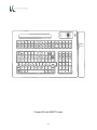
APPENDIX A
SERIES 500 POS STANDARD KEYBOARD LAYOUTS
A1
APPENDIX B
KEYBOARD CABLE/CONNECTOR DATA
B1
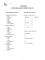
APPENDIX C
ASC11 CHARACTER SET
C1
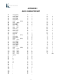
APPENDIX D
101/102-KEY KEYBOARD KEY NUMBER TO SCAN CODE CROSS
REFERENCE
D1
LIST OF TABLES
TABLE 1.
SERIES 500 POS KEYBOARD - TYPICAL CONTROLS AND
INDICATORS
8
LOCAL MODE PROGRAMMING FUNCTION CODES AND
DEFAULT SETTINGS
9
TABLE 3.
LOCAL MODE PROGRAMMING INSTRUCTIONS
15
TABLE 4.
LOCAL PROGRAMMING COMMANDS FOR KEY MAKE/BREAK
AND EXTENDED FUNCTIONS
29
TABLE 5.
REMOTE PROGRAMMING MODE COMMANDS
34
TABLE 6.
RMOTE PROGRAMMING COMMANDS FOR KEY
MAKE/BREAK CODE
48
TABLE 2.
Series 500 POS Keyboard
FEDERAL COMMUNICATIONS COMMISSION
RADIO FREQUENCY INTERFERENCE
STATEMENT
NOTICE
This equipment complies with the limits for a Class A computing
device in accordance with the specifications in Part 15 of FCC rules
which are designed to minimize radio frequency interference in the
installation; however, there is no guarantee that radio or television
interference will not occur in any particular installation. If this
equipment does cause interference to radio or television reception,
which can be determined by turning the equipment off and on while
the radio or television is on, the user is encouraged to try to correct
the interference by one or more of the following measures:
• Reorient the radio or television receiving antenna
• Relocate the keyboard with respect to the receiver
• Move the keyboard away from the receiver
If necessary the user should consult the dealer or an experienced radio/television
technician for additional suggestions. The user may find the following booklet
prepared by the Federal Communications Commission helpful: "How to Identify and
Resolve Radio/TV Interference Problems". This booklet is available from the U.S.
Government Printing Office Washington, DC 20402. Order stock number 004-00000345-4.
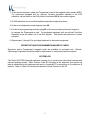
Series 500 POS Keyboard
SCOPE
This user's guide provides the information and procedures needed to install,
operate and program your Series 500 POS Keyboard. Differences in models and
optional features are described in this manual, where applicable. It is suggested
that the entire manual be read before attempting installation or programming. If
assistance is needed that is beyond the coverage provided in this guide, please
contact Customer Service:
Ultimate Technology Corporation
100 Rawson Road
Victor New York, 14564
Phone: (800) 349-0546
Fax: (585) 924-1434
SPECIAL NOTE
When this publication was written, every effort was made to ensure that information in this
document was complete, accurate, and up to date. Ultimate Technology Corporation assumes no
responsibility for errors beyond its control. Ultimate Technology Corporation also cannot
guarantee that changes in software and equipment made by other manufacturers, and referenced
in this guide, do not effect the applicability of the information in this manual. If assistance is
needed, please contact Customer Service at the address or phone number given above.
CAUTION
RISK OF ELECTRIC SHOCK
DO NOT OPEN
TO REDUCE THE RISK OF ELECTRIC SHOCK,
DO NOT OPEN KEYBOARD ENCLOSURE WHEN
KEYBOARD IS CONNECTED TO SYSTEM.
REFER SERVICING TO QUALIFIED SERVICE
PERSONNEL.
WARNING:
TO PREVENT FIRE OR SHOCK HAZARD, DO NOT EXPOSE THE KEYBOARD
TO RAIN OR MOISTURE.
Contents of this publication may be changed without notice and shall not be regarded as a warranty.
Series 500 POS Keyboard
Figure 1. Typical Point-of-Sale station with standard QWERTY Series 500 keyboard
Series 500 POS Keyboard
PRODUCT INFORMATION
MODEL DESCRIPTION
Series 500 POS Keyboards are point-of-sale (POS) keyboards designed for use with a PC or
ASCII terminal. These keyboards have total flexibility in keyboard layout coupled with an extensive
programming capability. Each keyboard contains a built-in magnetic stripe reader (MSR), two
serial ports, two cash drawer status ports, a main keyboard port, and an auxiliary keyboard port.
The Series 500 POS Keyboard provides both the hardware and firmware interfaces necessary to
fully integrate a modular "open system" POS workstation when attached to a PC or terminal, and
connected with a printer, cash drawer and display of the users choice.
FEATURES
CHOICE OF KEYBOARD TYPES
• Full travel, standard size keys - up to 112 keys
• Full travel, compact size keys - up to 144 keys
• Flat panel (micro motion), standard size - 112 keys
• Flat panel (micro motion), compact size - 144 keys
TWO CASH DRAWER PORTS
•Status monitoring
Autosend (Unsolicited)
Polling (Solicited)
•Optional cash drawer firing
All key locations are available
permanently printed or re-legendable. Full travel
keycaps have removable plastic covers for relegending. Flat panel membrane versions are relegendable by use of interchangeable overlays.
AUX PC KEYBOARD PORT
• For data entry when full alphanumeric capability is
needed
• For programming key codes (local method)
• For keyboard port compatible peripherals (bidirectional)
Standard keyboard configurations
including QWERTY and typical POS layouts are
available. Custom configurations of any number of
keys are also available.
TWO RS232 PORTS
• Serial peripherals
• Main communications port when used as a
terminal
• Hardware and software handshaking
• Selectable baud rates (300 bps - 57.6 Kbps)
FULLY USER PROGRAMMABLE
• Local (PC Keyboard)
• Remote (from Host)
• Download (Cloning)
All keys can be reprogrammed to output
any code. Single wide, double wide, and quad
keys can be placed anywhere on the keyboard.
Spacers are available for unused key locations.
32K NVRAM BUILT-IN
• 2048 16 character memory locations
• Control totals
• Other purposes
BUILT-IN MAGNETIC STRIPE READER
• 2 track, 3 format
• Programmable for prefix, suffix, separators and
audible annunciation
MAGNETIC
STRIPE
SECURITY
• Keyswitch optional
CARD
THREE LED INDICATORS
• User programmable
BUILT-IN AUDIBLE BEEPER
• Programmable
• Selectable tone and duration
CONTROLLED
BUILT-IN DIAGNOSTICS
• Self test
2
OPTIONAL PEDESTAL MOUNT
2
SPECIFICATIONS
DIMENSIONS
• Depth - 8 Inches
• Width - 13 Inches
• Height - 3 Inches
ENVIRONMENT
• Storage temperature -20° to 70°C (-68° to 158°F)
• Operating temperature 0° to 50°C (32° to 122°F)
APPROVALS
• FCC Class A
• UL recognized
• UL recognized (Canada)
WEIGHT
• 3.5 pounds (avg)
ELECTRICAL
• 135 - 185mA at 5VDC (supplied from host)
• 3-volt lithium battery (battery backup for memory
data retention when host source voltage removed)
SERVICE AND WARRANTY
Series 500 POS Keyboards come with a one-year parts and labor warranty. Assistance and
customer service is always available from Ultimate Technology Corporation's Customer Service
representative. If the dealer or your service provider cannot answer your question or provide
satisfactory service, please call our sales and technical support department. When calling for
assistance or service information, please have available the model number, part number and
serial number of the keyboard. This information is found on a decal located on the bottom of the
keyboard.
If the keyboard needs to be returned to a repair facility, please use the original packing material
and shipping carton. It is recommended that one set of packing material be retained for this
purpose.
The address and telephone numbers to be used for assistance, service, and warranty information
is:
Ultimate Technology Corporation
100 Rawson Road
Victor, New York 14564
Phone: (800) 349-0546
Fax: (585) 924-1434
3
INSTALLATION
UNPACKING AND INSPECTION
1. Examine the exterior of the shipping carton for signs of abuse or damage that may have
occurred during transport. Report all evidence of damage or abuse to shipper and dealer.
NOTE
If any damage may have occurred during transport, examine
keyboard and accessories carefully before performing any set-up
procedures. Return damaged keyboards to the dealer. See
Service paragraph.
2. Open top of shipping carton and carefully remove the keyboard and accessories.
3. Remove shipping retainers and protective covers from the keyboard and accessories.
NOTE
Retain a set of shipping retainers, protective covers, and the
shipping carton. Use these items whenever keyboard is to be
shipped.
4. Inventory and inspect the keyboard and other accessories listed below for damage.
• Keyboard
• One 8-foot cable (determined by configuration ordered)
Part No. CAB20133 - 5 pin DIN keyboard cable for AT & PC/XT, Data General
or
Part No. CAB20137 - 6 pin Mini DIN keyboard cable for PS2, TVI9070
or
Part No. CAB20134 - 8 pin modular keyboard cable for IBM 3151
• Secure Magnetic Card
• Programmer's Magnetic Card
• Series 500 POS Keyboard Programming & User's Guide
4
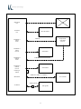
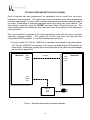
EXTERNAL CONNECTIONS
As required by the hardware configuration, connect the keyboard to its host computer and other
peripheral devices as shown in Figures 2 and 3. Note that the specific use for each connector on
the keyboard is marked adjacent to each connector. Depending on the make and model of the
user's equipment, the following cables and/or adapters may need to be supplied by the user to
complete the installation:
Standard 6-foot cable, 6-Pin Modular to 6-Pin Modular - UTC Part No. CAB20137 or equivalent
Keyboard adapter 2-Inch, 5 Pin DIN Male to 6-Pin Mini DIN Female - UTC Part No.900-0839 or equivalent
Keyboard adapter 12-Inch, 5 Pin DIN Female to 6 Pin Mini Din Male - UTC Part No. 901-5009A or equivalent
DRAWER JUMPER CONNECTIONS (PRINTER FIRED)
As shown on Figure 3, the Series 500 Keyboard has two status cash drawer ports. Each port is
selectable by use of the jumper connector located next to the MAIN keyboard connector. This
jumper connector is used to make the keyboard compatible with the different printer and cash
drawer connections required by various manufacturers.
Jumper pin set A and B is used with cash drawer 1: pin set C and D is used with cash drawer 2.
Installing the jumper on the B (drawer 1) and D (drawer 2) side of the connector causes the status
signal from the cash drawer to be applied on pin 2 of the related cash drawer port. Installing the
jumper on the A (drawer 1) and C (drawer 2) side of the connector causes the status signal from
the cash drawer to be applied on pin 6 of the related cash drawer port which allows pin 2 to be
used to open the drawer. Shown below are the pin connections for the cash drawer ports for each
position of jumper. Identified by an "X" are the jumper setting used with typical Epson and Ithaca
Peripheral devices.
PRINTER 1, 2 PINOUTS
DRIVER 1, 2
DRAWER 1, 2
JUMPER ON A OR C SIDE
DRAWER 1, 2
JUMPER ON B OR D SIDE
1 - SOLENOID GND
1 - SOLENOID GND
1 - SOLENOID GND
2 - SOLENOID GND/STATUS +
2 - SOLENOID GND
2 - STATUS +
3 - STATUS GND
3 - STATUS GND
3 - STATUS GND
4 - SOLENOID +
4 - SOLENOID +
4 - SOLENOID +
5 - SOLENOID GND
5 - SOLENOID GND
5 - SOLENOID GND
6 - NO CONNECTION
6 - STATUS +
6 - STATUS +
EPSON
X
ITHACA PERIPHERALS SERIES
50,60
X
5
Main RS232
Port
Aux RS232
Port
Cash Drawer 1
(Driver)
Port In
Bar Code Scanner
CAB20138
Receipt Printer
Cash Drawer
Port 1 & 2
Cash Drawer 1
(Driver)
Port Out
Cash Drawer 2
(Drawer)
Port In
Cash Drawer 1
CAB20138
Cash Drawer 2
(Drawer)
Port Out
Cash Drawer 2
Drawer Type
Jumpers
CAB20133 or CAB20137 or CAB20134
PC or Terminal
Main KB Port
Adapter (optional)
Aux KB Port
PS2 Type KB
6
Figure 2. Typical keyboard external connections
7
Figure 3. Keyboard external connectors - rear view
8
OPERATION
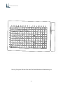
CONTROLS AND INDICATORS
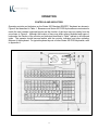
Operating controls and indicators on the Series 500 Standard QWERTY Keyboard are shown in
Figure 4 and described in Table 1. Because most Series 500 POS Keyboards are customized to
match the user's needs, keyboard layouts and the function of the keys may vary widely from the
one shown in Figure 4. Although the location of keys may differ among keyboard and types of
keyboards, the function of the controls and indicators described in Table 1 pertain to all keyboard
types. The operator should become familiar with the controls, indicators and other operating
features of the keyboard. For typical keyboard layouts of other Series 500 POS Keyboards, refer
to Appendix A.
9
Figure 4. Series 500 POS keyboard - typical controls and indicators
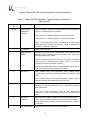
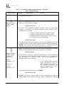
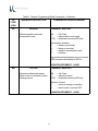
Table 1. Series 500 POS Keyboard - Typical Controls and Indicators
(See Figure 4)
Index
No.
1 through 3
Name
Light Emitting
Diode (LED)
Indicators
Function
LED (1) SECURE - When on, indicates keyboard is secured(locked);
when off, indicates keyboard is unlocked.
LED (2) When on, indicates keyboard is in CAP LOCK mode.
LED (3) When on, indicates keyboard is in NUM LOCK mode.
When in local programming mode - the status (on or off) of LEDs
varies depending on status of programming. Refer to programming
instructions contained in this guide.
4
Sound Port
Beeper annunciator port.
5
Magnetic Stripe
Reader
Magnetic card reader used to read standard format customer credit
and bank cards for normal business transactions when the card is
passed (swiped) through reader.
Used to read Operator's Card to secure or unlock use of keyboard
when the card is swiped through reader. LED (1) is on when
keyboard is secured and off when unlocked.
Used to read Programmer's Card to enable keyboard programming in
local mode when the card is swiped through reader.
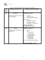
6
ENTER Key
When pressed during local programming mode, initiates various
program actions. Refer to programming instructions contained in this
guide.
When pressed during normal business operation, enters numeric
keyboard and other keyed data as defined by the user.
7
Numeric Keypad
Numeric keypad that may be used during normal business
operations to enter numeric values or can be customized to represent
user defined items.
Used during local programming mode to enter programming
commands. Refer to programming instructions contained in this
guide.
8
Keyswitch
(Optional)
When set to AUX position, enables keyboard programming in local
mode. The remaining two positions can be programmed for Macros
and/or security locking. Refer to programming instructions contained
in this guide.
9
Pen/Pencil Holder
Storage location used to hold user's pens or pencils.
10
All Other
User Defined Keys
User defined keys programmed by user/developer.
11
PROGRAMMING
PROGRAMMING KEYBOARD OPERATING PARAMETERS
The operating parameters of the keyboard can be configured (programmed) remotely from the
host computer or locally at the keyboard. Keyboard programming in the remote mode sets the
keyboard parameters as commanded by the host computer input applied at the main
communications port. Selection of the local programming mode enables keyboard parameter
setup locally at the keyboard. Note that all keyboards come from the factory programmed with a
default set of parameters.
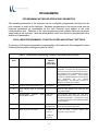
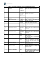
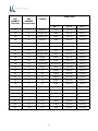
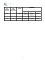
LOCAL MODE PROGRAMMING - FUNCTION CODES AND DEFAULT SETTINGS
A summary of all keyboard parameters programmable in the local mode, their assigned Function
Codes and factory default settings are given in Table 2.
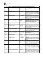
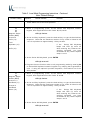
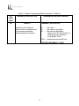
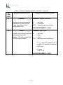
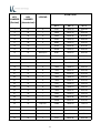
Table 2. Local Mode Programming Function Codes and Default Settings
FUNCTION
CODE
PARAMETER
DEFAULT
SETTING
(XXh = Hex
Code In ASCII)
REMARKS
00
Program Keyboard Primary Keys
See default
Used to program primary keys on Series 500
Keyboard. The keys can be programmed to
have primary and secondary levels of function.
The primary function is activated when only the
designated key is pressed. The secondary
function is activated when both the Sec Op key
and
designated
key
are
pressed
simultaneously. Use Function Code 01 to
program secondary key functions.
01
Program Keyboard Secondary Keys
See default
See remarks above.
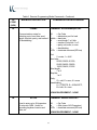
02
Copy Primary Keys to Secondary
Keys
08
Enable/Disable
Magnetic
Reader (MSR) Tracks
09
10
Stripe
Used to copy primary key code into key
secondary position.
Channels 1,2
enabled
The magnetic card reader can read three
formats of information, two at any one time, on
standard format cards. This function is used
to select which tracks on the MSR are enabled
and/or disabled.
MSR Beep Configuration
Beep on good
and bad read
Useful for indicating a good or bad reading
when card swiped through reader.
MSR Channel 1,3 Prefix
% (25h) for
format 1
Used to send a prefix
magnetic card channel.
; (3Bh) for
format 3
12
before
the
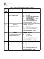
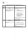
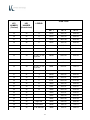
Table 2. Local Mode Programming Function Codes and Default Settings
11
MSR
Channel
Separator
1,3
Field
^ (5Eh) for
format 1
Used to send a field separator between
fields of the magnetic card channel.
= (3Dh) for
format 3
12
MSR Channel 1,3 Suffix
?<CR>
(3Fh,0Dh)
for both
format 1 and
3
Used to send suffixes
magnetic card channels.
13
MSR
Channel
Separator
: (3Ah) for
format 3
Used to send an account separator on
the magnetic card channel.
14
MSR C h a n n e l 2 P r e f i x
; (3Bh) for
format 2
Used to send a prefix
magnetic card channel.
15
MSR Channel 2 Field Separator
= (3Dh) for
format 2
Used to send a field separator between
fields of the magnetic card channel.
16
MSR Channel 2 Suffix
?<CR>
(3Fh,0Dh)
for format 2
Used to send a suffix
magnetic card channel.
17
MSR Bad Read Track 1,3
M1!<CR>
(4Dh,31h,21
h,
0Dh)
Used to send a key sequence to the
host computer upon a bad magnetic
card read.
18
MSR Bad Read Track 2
M2!<CR>
(4Dh,32h,21
h,
0Dh)
Used to send a key sequence to the
host computer upon a bad magnetic
card read.
19
MSR Sending
Send any
track
Used to send MSR data if one or both
tracks are good.
0 = send any track; 1 = send if both
tracks are good.
20
RS232 Port 0 Baud Rate
9600 Baud
Rate
Used to select a baud rate for Port 0.
Baud rates available are: 300, 600,
1200, 2400, 4800, 9600, 19200, 38400
and 57600.
21
RS232 Port 0 Stop Bits
2 stop bits
Used to select number of stop bits, 1
or 2, used with Port 0.
22
RS232 Port 0 Parity
No parity
Used to select parity used with Port 0.
Selections available are: no parity, odd
parity or even parity.
23
RS232 Port 0 Handshaking
Both
Used to select method of handshaking used
with Port 0. Selections available are: none,
CTS/RTS, XON/XOFF or both.
3
Account
13
after
after
after
the
the
the
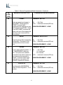
Table 2. Local Mode Programming Function Codes and Default Settings
24
RS232 Port 0 Word Length
User defined
Used to change the word length, 7 or 8 bits,
of the data at Port 0.
25
RS232 Port 0 Prefix
None
Used to place a prefix before the packet of
data before it is sent out of the keyboard
Main Port. (This function is inactive if Port
0 is the main port.)
26
RS232 Port 0 Suffix
<CR> (0Dh)
Used to place a suffix after the packet of
data before it is sent out of the keyboard
Main Port. (This function is inactive if Port
0 is the main port.)
30
RS232 Port 1 Baud Rate
9600 Baud
Rate
Used to select a baud rate for Port 1. Baud
rates available are: 300, 600, 1200, 2400,
4800, 9600, 19200, 38400 and 57600.
31
RS232 Port 1 Stop Bits
2 stop bits
Used to select number of stop bits, 1 or 2,
used with Port 1.
32
RS232 Port 1 Parity
No parity
Used to select parity used with Port 1.
Selections available are: no parity, odd
parity or even parity.
33
RS232 Port 1 Handshaking
Both
Used to select method of handshaking used
with Port 1. Selections available are: none,
CTS/RTS, XON/XOFF or both.
34
RS232 Port 1 Word Length
User defined
Used to change the word length, 7 or 8 bits,
of the data at Port 1.
35
RS232 Port 1 Prefix
None
Used to place a prefix before the packet of
data before it is sent out of the keyboard
Main Port.
36
RS232 Port 1 Suffix
<CR> (0Dh)
Used to place a suffix after the packet of
data before it is sent out of the keyboard
Main Port.
38
Keyswitch Position 1 MAKE
No output
Used to program the MAKE codes of the
keyswitch. When the key is turned into
position 1, the switch can send macros
and/or perform an internal secure (lock).
39
Keyswitch Position 1 BREAK
No output
Used to program the BREAK codes of
the keyswitch. When the key is turned
o u t o f p o s i t i o n 1 , t h e s w i tc h c a n s e n d
macros and/or perform an internal
secure (lock).
40
Keyswitch Position 2 MAKE
No output
Used to program the MAKE codes of
the keyswitch. When the key is turned
into position 2, the switch can send
macros and/or perform an internal
14
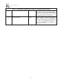
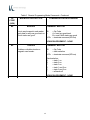
Table 2. Local Mode Programming Function Codes and Default Settings
s e c u r e ( l o ck).
41
Keyswitch Position 2 BREAK
No output
Used to program the BREAK codes of
the keyswitch. When the key is turned
out of position 2, the switch can send
macros and/or perform an internal
secure (lock).
42
Keyswitch Position 3 MAKE
No output
U s e d t o program the MAKE codes of
the keyswitch. When the key is turned
into position 3, the switch can send
macros and/or perform an internal
secure (lock).
43
Keyswitch Position 3 BREAK
No output
Used to program the BREAK codes of
the keyswitch. When the key i s t u r n e d
out of position 3, the switch can send
macros and/or perform an internal
secure (lock).
44
Keyswitch Polling
User
defined
Allows the user to poll for keyswitch
1,2, or 3 MAKE/BREAK codes.
Two
options are available: 0 = unsolicited
mode in which codes are sent
whenever the keyswitch is rotated, or 1
= solicited mode in which codes are
sent only when a B7 command is
executed.
45
Drawer 1 Open
D1+
(44h,31h,2B
h)
Used to set up a unique sequence of
keys so host computer can determine if
drawer 1 is open or closed.
46
Drawer 1 Closed
D1(44h,31h,2D
h)
Used to set up a unique sequence of
keys so host computer can determine if
drawer 1 is open or closed.
47
Drawer 2 Open
D2+
(44h,32h,2B
h)
Used to set up a unique sequence of
keys so host computer can determine if
drawer 2 is open or closed.
48
Drawer 2 Closed
D2(44h,32h,2D
h)
Used to set up a unique sequence of
keys so host computer can determine if
drawer 2 is open or closed.
49
Poll/Unsolicited Cash Drawer Status
Unsolicited
Allows the user to poll for cash drawer status,
instead of sending it each time it changes
state, open or closed.
Two options are
available: Send on change or transition, or
send only with poll command CDCONT.
70
Indicator Lights Mode
Command
mode of
operation
Used to select if the CAPS (2) and NUM (3)
LOCK indicators function in the same manner
as a PC. Two options are available: PC mode
or Command mode (Lights Command). Note
that in the PC mode control of the indicators
will be transferred to other higher priority
commands if applied.
15
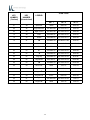
Table 2. Local Mode Programming Function Codes and Default Settings
71
Enable/Disable Key Clicks
On
Enables or disables audible key clicks.
0 = off; 1 = on
80
Define Left Shift Key
Key 44
See
illustration in
Appendix D
If auxiliary keyboard connected to the Series
500 Keyboard is other than a standard 101 or
102- key keyboard, used to define where the
AUX keyboard SHIFT keys are located. Refer
to Appendix D.
81
Define Right Shift Key
Key 57 See
illustration in
Appendix D
Same as Function Code 80 above.
82
Define Left Control Key
Key 58
See
illustration in
Appendix D
If auxiliary keyboard connected to the Series
500 Keyboard is other than a standard 101 or
102-key keyboard, used to define where the
AUX keyboard CONTROL keys are located.
Refer to Appendix D.
83
Define Right Control Key
Key 64
See
illustration in
Appendix D
Same as Function Code 82 above.
84
Define Left Alternate Key
Key 60
See
illustration in
Appendix D
If auxiliary keyboard connected to the Series
500 Keyboard is other than a standard 101 or
102-key keyboard, used to define where the
AUX keyboard ALTERNATE keys are located.
Refer to Appendix D.
85
Define Right Alternate Key
Key 62
See
illustration in
Appendix D
Same as Function Code 84 above.
86
Programming Mode Enter Macro
None
Reserved for future use.
87
Lock Mode Enter Macro
None
Reserved for future use.
90
Send System Log
None
Used to read the Series 500 Keyboard system
log at the main port. For detailed information
about retrieving the system log data, refer to
the Maintenance Section of this manual.
91
Main Port Select
Port 0
Used to select either the main keyboard port
or main RS232 port as the main
communications port.
96
Set Secure Mode
None
Used to toggle between secure or unsecure
mode.
97
Default Keyboard
None
Used to reset Series 500 Keyboard to all
programmed default settings.
98
Download Keyboard
None
Once a Series 500 Keyboard has been
programmed, the parameters can be copied
(cloned) from the source keyboard to other
keyboards.
This feature saves time and
reduces errors when programming more than
16
Table 2. Local Mode Programming Function Codes and Default Settings
one keyboard. It is also useful for remote
keyboard setup and when making changes in
key codes. To download keyboard settings,
refer to the procedure given at the rear of the
Programming Section in this manual.
99
Exit Program Mode
None
17
Used to terminate the programming mode.
When activated, causes all programmed
changes to be saved and the keyboard to do a
warm boot. Exiting programming mode can
also be accomplished by swiping the
Programmer's card.
LOCAL MODE PROGRAMMING INSTRUCTIONS
To program the Series 500 Keyboard in the local mode proceed as follows:
1. Swipe the Programmer's card supplied with the keyboard in the magnetic stripe reader
(MSR). For Series 500 Keyboards equipped with the optional 3-position keyswitch
adjacent to the LED indicators, set the switch to the AUX position and enter 882 on the
keyboard numeric keypad.
2. All LED indicators turn on and the keyboard enunciator beeps three times.
3. After step 2 is complete, LED indicator (1) will flash continuously to indicate that the
keyboard programming mode is active.
4. For a summary of the parameters that can be programmed in the local mode, refer to Table
2 preceding.
5. Follow the instructions given in Table 3 for the applicable Function Code(s) to program the
keyboard for the desired parameter(s). Note that sequence of instructions provided in
Table 3 is in Function Code numerical order.
6. When programming is complete, exit the local programming mode by typing 99 on the
Series 500 Keyboard numeric keypad or by swiping the Programmer's card. If using the
optional 3-position keyswitch, move switch out of the AUX position. This returns the
keyboard to normal operation.
NOTE
Some programming options may not be
activated until the keyboard is re-powered.
Serial port communication selections -Function Codes 10-24; 30-34; 91;
18
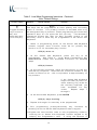
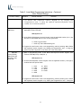
Table 3. Local Mode Programming Instructions - Continued
Note: *Default Settings
Function Code(s)
00
01
Program Primary
Key Functions
(00) and
Secondary Key
Functions (01)
Operation
Normal Indication
Remarks
NOTE
The keys can be programmed to have primary and secondary
levels of function.
The primary function is activated when only
the designated key is pressed. When programming the secondary
operation keys, do not press the Sec Op Key.
The secondary
operations access key (Sec Op Key) provides access to the
secondary level of each key as programmed in the Series 500
Keyboard.
1.
While in programming mode, at the Series 500 Keyboard
numeric keypad, enter Function Code 00 for primary key
function or 01 for secondary key function.
LED (2) turns on.
2.
At
the
Series
500
Keyboard,
pres s the key to be
programmed.
See Table 4 - Local Mode Programming Key
MAKE/BREAK Codes and Extended Functions for detailed
steps.
LED (2) flashes.
3.
At the auxiliary keyboard, press the desired key or type the
desired key sequence. Note that the maximum number of key
codes is limited to 24 - this is equivalent to approximately 12
key strokes.
If the Series 500 Keyboard
beeps and LED (2) turns off
while entering key codes at
the auxiliary keyboard, you
have
exceeded
24
key
codes.
Repeat steps 1
through 3.
4.
At the Series 500 Keyboard, press ENTER.
LED (2) stops flashing.
5.
6.
Repeat 2 through 4 for next key to be programmed.
Exit
programming
primary/secondary
key
functions
pressing 00 on the Series 500 Keyboard numeric keypad.
by
7. Program the next function code or exit programming mode by
entering 99 on Series 500 Keyboard numeric keypad or by
swiping the Programmer's card.
If using the optional 3-
19
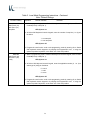
Table 3. Local Mode Programming Instructions - Continued
Note: *Default Settings
Function Code(s)
Operation
Normal Indication
Remarks
position keyswitch, move switch out of the AUX position.
02
Copy Primary Key
Functions to
Secondary Key
Positions
1. While in programming mode, at the Series 500 Keyboard numeric
keypad, enter Function Code 02.
LED (2) turns on.
2. At the Series 500 Keyboard, press the designated key to copy its
primary function into the secondary position.
3. Repeat 2 for next key to be programmed
4. When completed, press ENTER.
LED (2) turns off.
5. Program the next function code or exit programming mode by entering 99
on Series 500 Keyboard numeric keypad or by swiping the Programmer's
card. If using the optional 3-position keyswitch, move switch out of the
AUX position.
Note: A Sec Op Key or Sec Op Lock Key must be programmed in the
primary function mode in order to use secondary function codes.
08
Enable /Disable
Magnetic Stripe
Reader (MSR)
Tracks
1. While in programming mode, at the Series 500 Keyboard numeric
keypad, enter Function code 08.
LED (2) turns on.
2. At the Series 500 Keyboard numeric keypad, enter the applicable
number (1 through 6) to select the MSR track configuration per list
below.
1
2
3
4
5
6
=
=
=
=
=
=
Channel 1 enabled
Channel 2 enabled
Channel 3 enabled
Channels 1 and 2 enabled*
Channels 2 and 3 enabled
All channels disabled
LED (2) turns off.
3. Program the nex t function code or exit the local programming mode by
entering 99 on Series 500 Keyboard numeric keypad or by swiping the
Programmer's card. If using the optional 3-position keyswitch, move
switch out of the AUX position.
20
Table 3. Local Mode Programming Instructions - Continued
Note: *Default Settings
Function Code(s)
Operation
Normal Indication
Remarks
Note:
Disabling all format tracks will not disable the secure or
programming operations.
09
Magnetic Stripe
Reader (MSR)
Beeper
1. While in programming mode, at the Series 500 Keyboard numeric
keypad, enter Function code 09.
LED (2) turns on.
2. At Series 500 Keyboard numeric keypad, enter the applicable
number (1 through 4) to select magnetic stripe reader beeper
operation per list below.
1
2
3
4
=
=
=
=
beep on
beep on
beep on
no beep
good read for all enabled tracks
bad read for all enabled tracks
good or bad read of enabled tracks*
on good or bad reads
LED (2) turns off.
3. Program the next function code or exit the local programming mode
by entering 99 on Series 500 Keyboard numeric keypad followed by
ENTER or by swiping the Programmer's card. If using the optional
3-position keyswitch, move switch out of the AUX position.
10
11
12
13
Magnetic Stripe
Reader (MSR)
Channel 1,3
Prefix (10)
1. While in programming mode, at the Series 500 Keyboard numeric
keypad, enter applicable Function Code 10, 11, 12 or 13.
LED (2) flashes.
2. At the auxiliary keyboard, press the desired key or type the desired
key sequence. Note that the maximum number of key codes that
can be entered is limited to 24 - this is the equivalent to
approximately 12 key strokes.
Field
Separator (11)
If the Series 500 Keyboard
beeps and LED (2) turns off
while entering key codes at
the auxiliary keyboard, you
have exceeded 24 key codes.
Repeat steps 1 and 2.
Suffix (12)
Account
Separator (13)
3. At the Series 500 Keyboard, press ENTER.
LED (2) turns off.
4. Program the next function code or exit programming mode by
entering 99 on Series 500 Keyboard numeric keypad or by swiping
21
Table 3. Local Mode Programming Instructions - Continued
Note: *Default Settings
Function Code(s)
Operation
Normal Indication
Remarks
the Programmer's card. If using the optional 3-position keyswitch,
move switch out of the AUX position.
14
15
16
Magnetic Stripe
Reader (MSR)
Channel 2
Prefix (14)
1. While in programming mode, at the Series 500 Keyboard numeric
keypad, enter applicable Function Code 14, 15, or 16.
LED (2) flashes.
2. At the auxiliary keyboard, press the desired key or type the desired key
sequence. Note that the maximum number of key codes is limited to 24
- this is equivalent to approximately 12 key strokes.
Field
Separator (15)
If the
Series 500 Keyboard
beeps and LED (2) turns off
while entering key codes at the
auxiliary keyboard, you have
exceeded 24 key codes. Repeat
steps 1 and 2.
Suffix (16)
3. At the Series 500 Keyboard, press ENTER.
LED (2) turns off.
4. Program the next function code or exit programming mode by entering 99
on Series 500 Keyboard numeric keypad or by swiping the Programmer's
card. If using the optional 3-position keyswitch, move switch out of the
AUX position.
17
18
Magnetic Stripe
Reader (MSR)
Channel 1,3
Bad Read (17)
Channel 2
Bad Read
Macro (18)
1. While in programming mode, at the Series 500 Keyboard numeric
keypad, enter applicable Function Code 17 or 18.
LED (2) flashes.
2. At the auxiliary keyboard, press the desired key or type the desired key
sequence. Note that the max imum number of key codes is limited to 24
- this is equivalent to approximately 12 key strokes.
If the
Series 500 Keyboard
beeps and LED (2) turns off
while entering key codes at the
auxiliary keyboard, you have
exceeded 24 key codes. Repeat
steps 1 and 2.
3. At the Series 500 Keyboard, press ENTER.
LED (2) turns off.
22
Table 3. Local Mode Programming Instructions - Continued
Note: *Default Settings
Function Code(s)
Operation
Normal Indication
Remarks
4. Program the next function code or exit programming mode by entering 99
on Series 500 Keyboard numeric keypad or by swiping the
Programmer's card. If using the optional 3-pos ition keyswitch, move
switch out of the AUX position.
19
MSR Send
1. While in programming mode, at the Series 500 Keyboard numeric keypad, enter
applicable Function Code 19.
LED (2) turns on.
2. At the Series 500 Keyboard numeric keypad, enter the applicable number (0 or 1) per
list below to select MSR data from one or both good tracks.
0 = send any good track*
1 = send only if all enabled tracks good
3. Program the next function code or exit programming mode by entering 99 on Series
500 Keyboard numeric keypad or by swiping the Programmer's card. If using the
optional 3-position keyswitch, move switch out of the AUX position.
20 or 30
Comm (RS232)
Main Port 0 (20)
AUX Port 1 (30)
Baud Rate
1. While in programming mode, at the Series 500 keyboard numeric keypad, enter
Function Code 20 (Port 0) or 30 (Port 1).
LED (2) turns on.
2. At Series 500 Keyboard numeric keypad, enter the applicable number (1 through 9)
to select baud rate per list below.
1 = 300
2 = 600
3 = 1200
4 = 2400
5 = 4800
6 = 9600*
7 = 19200
8 = 38400
9 = 57600
LED (2) turns off.
3. Program the next function code or exit programming mode by entering 99 on Series
500 Keyboard numeric keypad or by swiping the Programmer's card. If using the
optional 3-position keyswitch, move switch out of the AUX position.
23
Table 3. Local Mode Programming Instructions - Continued
Note: *Default Settings
Function Code(s)
21 or 31
Main Port 0 (21)
AUX Port 1 (31)
Stop Bits
Operation
Normal Indication
Remarks
1. While in programming mode, at Series 500 Keyboard numeric keypad, enter Function
Code 21 (Port 0) or 31 (Port 1).
LED (2) turns on.
2. At Series 500 Keyboard numeric keypad, enter the number of stop bits (1 or 2) per
list below.
1 = one stop bit
2 = two stop bits*
LED (2) turns off.
3. Program the next function code or exit programming mode by entering 99 on Series
500 Keyboard numeric keypad or by swiping the Programmer's card. If using the
optional 3-position keyswitch, move switch out of the AUX position.
22 or 32
Main Port 0 (22)
AUX Port 1 (32)
Parity
1. While in programming mode, at Series 500 Keyboard numeric keypad, enter Function
Code 22 (Port 0) or 32 (Port 1).
LED (2) turns on.
2. At Series 500 Keyboard numeric keypad, enter the applicable number (0, 1 or 2) to
select type of parity per list below.
0 = none*
1 = odd
2 = even
LED (2) turns off.
3. Program the next function code or exit programming mode by entering 99 on Series
500 Keyboard numeric keypad or by swiping the Programmer's card. If using the
optional 3-position keyswitch, move switch out of the AUX position.
24
Table 3. Local Mode Programming Instructions - Continued
Note: *Default Settings
Function Code(s)
23 or 33
Main Port 0 (23)
AUX Port 1 (33)
Handshaking
Operation
Normal Indication
Remarks
1. While in programming mode, at Series 500 Keyboard numeric keypad, enter Function
Code 23 (Port 0) or 33 (Port 1).
LED (2) turns on.
2. At Series 500 Keyboard numeric keypad, enter the applicable number (0, 1, 2 or 3) to
select handshaking per list below.
0 = None
1 = CTS/RTS
2 = XON/XOFF
3 = Both*
LED (2) turns off.
3. Program the next function code or exit programming mode by entering 99 on Series
500 Keyboard numeric keypad or by swiping the Programmer's card. If using the
optional 3-position keyswitch, move switch out of the AUX position.
24 or 34
Main Port 0 (24)
AUX Port 1 (34)
Word Length
1. While in programming mode, at Series 500 Keyboard numeric keypad, enter Function
Code 24 (Port 0) or 34 (Port 1).
LED (2) turns on.
2. At Series 500 Keyboard numeric keypad, enter the applicable number (7 or 8) to
select word length per list below.
7 = 7 data bits
8 = 8 data bits
LED (2) turns off.
3. Program the next function code or exit programming mode by entering 99 on Series
500 Keyboard numeric keypad or by swiping the Programmer's card. If using the
optional 3-position keyswitch, move switch out of the AUX position.
25
Table 3. Local Mode Programming Instructions - Continued
Note: *Default Settings
Function Code(s)
25 or 35
Comm (RS232)
Main Port 0 (25)
AUX Port 1 (35)
Prefix
Operation
Normal Indication
Remarks
1. While in programming mode, at the Series 500 Keyboard numeric keypad,
enter applicable Function Code 25 (Port 0) or 35 (Port 1).
LED (2) flashes.
2. At the auxiliary keyboard, press the desired key or type the desired key
sequence. Note that the maximum number of key codes is limited to 24 - this
is equivalent to approximately 12 key strokes.
If the Series 500 Keyboard beeps
and LED (2) turns off while
entering key codes at the auxiliary
keyboard, you have exceeded 24
key codes. Repeat steps 1 and 2.
3. At the Series 500 Keyboard, press ENTER.
LED (2) turns off.
4. Program the next function code or exit programming mode by entering 99 on
Series 500 Keyboard numeric keypad or by swiping the Programmer's card. If
using the optional 3-position keyswitch, move switch out of the AUX position.
26 or 36
Comm (RS232)
Main Port 0 (26)
AUX Port 1 (36)
Suffix
1. While in programming mode, at the Series 500 Keyboard numeric keypad,
enter applicable Function Code 26 (Port 0) or 36 (Port 1).
LED (2) flashes.
2. At the auxiliary keyboard, press the desired key or type the desired key
sequence. Note that the maximum number of key codes is limited to 24 - this
is equivalent to approximately 12 key strokes.
If the Series 500 Keyboard beeps
and LED (2) turns off while
entering key codes at the auxiliary
keyboard, you have exceeded 24
key codes. Repeat steps 1 and 2.
3. At the Series 500 Keyboard, press ENTER.
LED (2) turns off.
Program the next function code or exit programming mode by entering 99 on
Series 500 Keyboard numeric keypad or by swiping the Programmer's card. If
using the optional 3-position keyswitch, move switch out of the AUX position.
38
1.
While
in
programming
26
mode,
at
the
Series
500
Keyboard
Table 3. Local Mode Programming Instructions - Continued
Note: *Default Settings
Function Code(s)
39
40
41
42
43
Keyswitch
Position 1
MAKE (38)
Operation
Normal Indication
Remarks
numeric keypad, enter applicable Function Code 38, 39, 40, 41,
4 2 o r 43 .
LED (2) flashes.
2.
Keyswitch
Position 1
BREAK (39)
At the auxiliary keyboard, type the desired MAKE OR BREAK
key sequence shown below and /or desired key sequence. Note
that the maximum number of key codes is limited to 24 - this is
equivalent to approximately 12 key strokes .
<882>001 = To enter into secure mode or MAKE
<882>002 = To exit out of secure mode or BREAK
Keyswitch
Position 2
MAKE (40)
If the Series 500 Keyboard
beeps and LED (2) turns off
while entering key codes at
the auxiliary keyboard, you
have
exceeded
24
key
codes. Repeat steps 1 and
2.
Keyswitch
Position 2
BREAK (41)
Keyswitch
Position 3
MAKE (42)
3.
At the Series 500 Keyboard, press ENTER.
Keyswitch
Position 3
BREAK (43)
4.
Program the next function code or exit programming mode by
entering 99 on Series 500 Keyboard numeric keypad or by
s w i p i n g t h e P r o g r a m m e r ' s c a r d . I f u s i n g t h e o p t i o n a l 3- p o s i t i o n
keyswitch, move switch out of the AUX position.
44
Poll
Keyswitch
1.
While in programming mode, at Series 500 Keyboard numeric
keypad, enter Function Code 44.
LED (2) turns off.
LED (2) turns on.
2.
At Series 500 Keyboard numeric keypad, enter the applicable
number (0 or 1) to select polling method per list below.
0 = Send on change or transition
1 = Send only with poll command B7
LED (2) turns off.
3. Program the next function code or exit programming mode by
entering 99 on Series 500 Keyboard numeric keypad or by
s w i p i n g t h e P r o g r a m m e r ' s c a r d . I f u s i n g t h e o p t i o n a l 3- p o s i t i o n
keyswitch, move switch out of the AUX position.
27
Table 3. Local Mode Programming Instructions - Continued
Note: *Default Settings
Function Code(s)
45
46
47
48
Drawer 1
Open (45)
Closed (46)
Operation
Normal Indication
Remarks
1. While in programming mode, at the Series 500 Keyboard numeric keypad, enter
applicable Function Code 45, 46, 47 or 48.
LED (2) flashes.
2. At the auxiliary keyboard, press the desired key or type the desired key sequence.
Note that the maximum number of key codes is limited to 24 - this is equivalent to
approximately 12 key strokes.
Drawer 2
Open (47)
Closed (48)
If the Series 500 Keyboard beeps and
LED (2) turns off while entering key
codes at the auxiliary keyboard, you
have exceeded 24 key codes. Repeat
steps 1 and 2.
3. At the Series 500 Keyboard, press ENTER.
LED (2) turns off.
4. Program the next function code or exit programming mode by entering 99 on Series
500 Keyboard numeric keypad or by swiping the Programmer's card. If using the
optional 3-position keyswitch, move switch out of the AUX position.
49
Poll/
Unsolicited
Cash Drawer Status
1. While in programming mode, at Series 500 Keyboard numeric keypad, enter Function
Code 49.
LED (2) turns on.
2. At Series 500 Keyboard numeric keypad, enter the applicable number (0 or 1) to
select status method per list below.
0 = Send on change or transition
1 = Send only with poll command CDSTATUS
LED (2) turns off.
3. Program the next function code or exit programming mode by entering 99 on Series
500 Keyboard numeric keypad or by swiping the Programmer's card. If using the
optional 3-position keyswitch, move switch out of the AUX position.
28
Table 3. Local Mode Programming Instructions - Continued
Note: *Default Settings
Function Code(s)
70
Indicator LED
Mode (70)
Operation
Normal Indication
Remarks
1. While in programming mode, at Series 500 Keyboard numeric keypad, enter Function
Code 70.
LED (2) turns on.
2. At Series 500 Keyboard numeric keypad, enter the applicable number (0 or 1) to
select LED mode of operation.
LED Mode
0 = Command mode of operation*
1 = PC mode of operation
LED (2) turns off.
3. Program the next function code or exit programming mode by entering 99 on Series
500 Keyboard numeric keypad or by swiping the Programmer's card. If using the
optional 3-position keyswitch, move switch out of the AUX position.
71
Enable/Disable
Keyboard Key
Clicks (71)
1. While in programming mode, at Series 500 Keyboard numeric keypad, enter Function
Code 71.
LED (2) turns on.
2. At Series 500 Keyboard numeric keypad, enter the applicable number (0 or 1) to
select key click mode of operation.
Key Click Mode
0 = off
1 = on*
LED (2) turns off.
3. Program the next function code or exit programming mode by entering 99 on Series
500 Keyboard numeric keypad or by swiping the Programmer's card. If using the
optional 3-position keyswitch, move switch out of the AUX position.
29
Table 3. Local Mode Programming Instructions - Continued
Note: *Default Settings
Function Code(s)
80
81
Define Position of
Left SHIFT Key
(80) and Right
SHIFT Key (81)
Operation
Normal Indication
Remarks
1. While in programming mode, at the Series 500 Keyboard numeric
keypad, enter Function Code 80 or 81.
LED (2) flashes.
2. At the auxiliary keyboard, hit the left SHIFT key if programming Function
Code 80 or right SHIFT key if programming Function Code 81.
3. At the Series 500 Keyboard, press ENTER.
LED (2) turns off.
4. Program the next function code or exit programming mode by entering 99
on Series 500 Keyboard numeric keypad or by swiping the Programmer's
card. If using the optional 3-position keyswitch, move switch out of the
AUX position.
82
83
Define Position of
Left CONTROL Key
(82) and Right
CONTROL Key (83)
1. While in programming mode, at the Series 500 Keyboard numeric
keypad, enter Function Code 82 or 83.
LED (2) flashes.
2. At the auxiliary keyboard, hit the left CONTROL key if programming
Function Code 82 or right CONTROL key if programming Function Code
83.
3. At the Series 500 Keyboard, press ENTER.
LED (2) turns off.
4. Program the next function code or exit programming mode by entering 99
on Series 500 Keyboard numeric keypad or by swiping the Programmer's
card. If us ing the optional 3-position keyswitch, move switch out of the
AUX position.
84
85
Define Position of
Left ALTERNATE
Key (84) and
Right ALTERNATE
Key (85)
1. While in programming mode, at the Series 500 Keyboard numeric
keypad, enter Function Code 84 or 85.
LED (2) flashes.
2. At the auxiliary keyboard, hit the left ALTERNATE key if programming
Function Code 84 or right ALTERNATE key if programming Function
Code 85.
3. At the Series 500 Keyboard, press ENTER.
LED (2) turns off.
4. Program the next function code or exit programming mode by entering 99
30
Table 3. Local Mode Programming Instructions - Continued
Note: *Default Settings
Function Code(s)
Operation
Normal Indication
Remarks
on Series 500 Keyboard numeric keypad or by swiping the Programmer's
card. If using the optional 3-position keyswitch, move switch out of the
AUX position.
90
Dump System Log
This is a command used to read out the Series 500 Keyboard system log data at the
main port. For detailed information about retrieving the system log data, refer to the
Maintenance Section of this manual.
91
Main Port Select
1. While in programming mode, at Series 500 Keyboard numeric keypad, enter Function
Code 91.
LED (2) turns on.
2. At Series 500 Keyboard numeric keypad, enter the applicable number (0 or 1) to
select LED mode of operation per list below.
0 = Keyboard Port 0 is main
1 = RS232 Port 0 is main
LED (2) turns off.
3. Program the next function code or exit programming mode by entering 99 on Series
500 Keyboard numeric keypad or by swiping the Programmer's card. If using the
optional 3-position keyswitch, move switch out of the AUX position.
Note: Must re-power Series 500 Keyboard in order to activate function code.
96
Set Secure Mode
1. While in programming mode, at Series 500 Keyboard numeric keypad, enter Function
Code 96
LED (2) turns on.
2. At Series 500 Keyboard numeric keypad, enter the applicable number (0 or 1) to
select override secure mode of operation per list below.
0 = not secure
1 = secure
LED (2) turns off.
3. Program the next function code or exit programming mode by entering 99 on Series
500 Keyboard numeric keypad or by swiping the Programmer's card. If using the
optional 3-position keyswitch, move switch out of the AUX position.
31
Table 3. Local Mode Programming Instructions - Continued
Note: *Default Settings
Function Code(s)
97
Default Keyboard
Operation
Normal Indication
Remarks
1. While in programming mode, at Series 500 Keyboard numeric keypad, enter Function
Code 97.
LED (2) turns on.
2. At Series 500 Keyboard numeric keypad, enter the applicable number (0 or 1) to
select mode of default operation per list below. Note selection of 1 below resets the
Series 500 Keyboard to all programmed default key and port settings.
0 = Exit default mode
1 = Default mode
3. Program the next function code or exit programming mode by entering 99 on Series
500 Keyboard numeric keypad or by swiping the Programmer's card. If using the
optional 3-position keyswitch, move switch out of the AUX position.
98
Once a Series 500 Keyboard has been programmed, the parameters can be copied
(cloned) from the source keyboard to other keyboards. This feature saves time and
reduces errors when programming more than one keyboard. It is also useful for remote
keyboard setup and when making changes in key codes. This command is used to
initiate the download of keyboard settings as described in the procedure given at the
rear of the Programming Section in the this manual.
99
Exit Program
Mode
Used to terminate the programming mode. When activated, causes all programmed
changes to be saved into non-volatile RAM and the keyboard to do a warm boot. Exiting
programming mode can also be accomplished by swiping the Programmer's card.
Download
LOCAL MODE PROGRAMMING
KEY MAKE/BREAK CODES AND EXTENDED FUNCTIONS
There are two scan codes assigned to each key, one for when the key is depressed (MAKE
code) and the other for when the key is released (BREAK code). Generally, all keys are
programmed to output both MAKE and BREAK codes. The SHIFT, CONTROL and ALTERNATE
keys are always programmed to output MAKE and BREAK codes so that the system can tell if the
key is being held down. Other programming commands are provided in the local programming
mode to enable the user to customize the keyboard output. These commands entered at the
Series 500 Keyboard numeric keypad are summarized in Table 4. Some typical programming
examples using these commands follow the table.
32
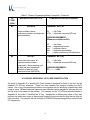
Table 4. Local Programming Commands For Key MAKE/BREAK And Extended Functions
SERIES 500
KEYBOARD
NUMERIC
KEYPAD NO.
DESCRIPTION
0
Aborts changes to macros.
1
Defines where the output of MAKE codes end and BREAK codes start. Prior
to this command, all codes are sent when the keys are pressed (MAKE
codes). After command, all codes are sent when keys are released (BREAK
codes).
2
Defines where repeating function of keys start. After command, all keys
repeat code when keys are held down past repeat time.
3
This command overrides PC settings for key. Key sends code as typed on
BREAK.
4
This command overrides PC setting for repeat. Key sends code as typed on
MAKE and BREAK.
5
This command removes all BREAK codes from the macros except for SHIFT,
CONTROL and ALTERNATE keys.
6
NOTE: Only available in 00 and 01 commands.
Defines the position of a key on the Series 500 Keyboard. Note that a Sec Op
Key must be defined on the Series 500 Keyboard to enable programming of
secondary-level key codes.
7
NOTE: Only available in 00 and 01 commands.
Defines the position of a Sec Op Lock Key on the Series 500 Keyboard.
9
Used to erase the macro from the primary and/or secondary key position.
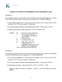
EXAMPLE 1.
This example programs where the Series 500 Keyboard MAKE codes end and BREAK codes
start using the "A" key.
1. Place the Series 500 Keyboard in local programming mode.
2. At the Series 500 Keyboard numeric keypad, enter 00 or 01.
33
3. At the Series 500 Keyboard, press the key to be programmed.
4. At the auxiliary keyboard, press and hold the "A" key.
5. At the Series 500 Keyboard numeric keypad, enter 1.
6. At the auxiliary keyboard, release the "A" key.
7. At the Series 500 Keyboard, press ENTER to complete programming of the key.
8. Repeat steps 3 through 7 to program another key.
9. To exit the programming mode, enter 00 99 at the Series 500 Keyboard numeric keypad.
EXAMPLE 2.
This example programs the Series 500 Keyboard to start repeat mode of key using the "A" key.
1. Place the Series 500 Keyboard in local programming mode.
2. At the Series 500 Keyboard numeric keypad, enter 00 or 01.
3. At the auxiliary keyboard, press and hold the "A" key.
4. At the Series 500 Keyboard numeric keypad, enter 2.
5. At the auxiliary keyboard, release the "A" key.
6. At the Series 500 Keyboard, press ENTER to complete programming of the key.
7. Repeat steps 3 through 7 to program another key.
8. To exit the programming mode, enter 00 99 at the Series 500 Keyboard numeric keypad.
EXAMPLE 3.
This example programs a Sec Op Key on the Series 500 Keyboard.
1. Place the Series 500 Keyboard in local programming mode.
2. At the Series 500 Keyboard numeric keypad, enter 00 or 01.
3. At the Series 500 Keyboard, press the key to be programmed.
4. At the Series 500 Keyboard numeric keypad, enter 6 (Sec Op) or 7 (Sec Op Lock).
34
5. At the Series 500 Keyboard, press ENTER to complete programming of the key.
6. Repeat steps 3 through 5 to program another key.
7. To exit the programming mode, enter 00 99 at the Series 500 Keyboard numeric keypad.
EXAMPLE 4.
This example erases the macro from the primary and/or secondary key position on the Series 500
Keyboard.
1. Place the Series 500 Keyboard in local programming mode.
2. At the Series 500 Keyboard numeric keypad, enter 00 (for primary keys) or 01 (for secondary
keys).
3. At the Series 500 Keyboard, press the key to be erased.
4. At the Series 500 Keyboard numeric keypad, enter 9.
5. Repeat steps 3 and 4 to erase another key.
6. To exit the programming mode, enter 00 99 at the Series 500 Keyboard numeric keypad.
35
PROGRAMMING IN REMOTE MODE
Programming in the remote mode requires the use of a supplemental program that is run on the
host computer. If using an IBM PC or compatible computer as the host, use program supplied by
Ultimate Technology Corporation when programming the keyboard. To load and use the
program, follow the instructions supplied with the program.
REMOTE MODE PROGRAMMING MACROS AND COMMAND SUMMARY
Refer to Table 5 for details about the commands and MACROS used when programming the
keyboard. A summary of the commands and their assigned Function Codes (OP Codes) and
mnemonic follows:
Note: OP Codes are single 8 bit entities in hexadecimal.
OP Code A0 - Key Macro Download Command (MACROK)
OP Code A1 - Macro Suffix/Prefix Download Command (MACROP)
OP Code A2 - Macro Rate Of Delay Command (SNDDLY)
OP Code A3 - Communications Setup Command (COMMP)
OP Code A4 - 40 Character Note Field (NOTES)
OP Code A5 - Define Shift, Control, Alternate Keys (SPCDGF)
OP Code A6 - Key Click (CLICKED)
OP Code A7 - Read Database Register (NVBDRD)
OP Code A8 - Write Database Register (NVBDWR)
OP Code A9 - Clear Database Register (NVBDCLR)
OP Code AD - Absolute Row/Column (RAWED)
OP Code AE - Secure Keyboard (SECURE)
OP Code AF - Ignore Everything To Carriage Return (COMMENT)
OP Code B0 - Indicator Light Command (LIGHT)
OP Code B1 - Beeper Activation Command (BEEPON)
OP Code B2 - Send Data to Port Command (SENDP)
OP Code B3 - Send Error Information Command (RDERROR)
OP Code B4 - Commit Changes to Memory (COMMIT)
OP Code B5 - Reset Keyboard Command (RESET)
OP Code B6 - Keyswitch Send (KSSND)
OP Code B7 - Keyswitch Poll Command (KSSTATUS)
OP Code B8 - MSR Send (MSRSND)
OP Code B9 - Enable/Disable Card Reader Command (CARDED)
OP Code BA - Card Good/Bad Read Annunciation Command (BEEPRD)
OP Code BB - Cash Drawer Status Command (CDCONT)
OP Code BC - Cash Drawer Open/Close Command (CDSTATUS)
OP Code BD - Auxiliary Keyboard ON/OFF Command (PORTE)
OP Code BE - Send Keyboard Parameters Command (VERSION)
OP Code BF - Send Keyboard Macros Command (GETSET)
36
NOTE
Always apply the COMMIT command (OP Code B4) after
programming the keyboard remotely to save the changes in the
NVRAM. Failure to use the COMMIT command after making
programming changes will result in the loss of the changes the
first time power is removed from the keyboard.
37
Table 5. Remote Programming Mode Commands - Continued
OP
CODE
(HEX)
MNEMONIC/DESCRIPTION
A0
MACROK
COMMAND/ACKNOWLEDGEMENT
COMMAND: A0krcCxDx.......<CR>
Download all key macros for Series
500 Keyboard.
Refer to Table 6 for further
explanation.
A0
k
= Op Code
= P to program Primary key
= S to program Secondary key
Missing means program both
Primary and Secondary Keys
r
= row in ASCII
c
= column in ASCII
Cx
= Low nibble of hex value
Dx
= High nibble of hex value
Where x = 0-9, A-F
<CR> = terminate command (0D hex)
ACKNOWLEDGEMENT: NONE
38
Table 5. Remote Programming Mode Commands - Continued
OP
CODE
(HEX)
MNEMONIC/DESCRIPTION
A1
MACROP
COMMAND/ACKNOWLEDGEMENT
COMMAND: A1aCxDx.......<CR>
Download macros for prefix/suffix.
A1
a
= Op Code
= macro to load in ASCII
range A-Z listed below
Cx
= key number
(refer to Appendix D)
Dx
= key number
(refer to Appendix D)
<CR> = terminate command (0D hex)
A
B
C
D
E
F
G
H
I
J
K
L
M
N
O
P
Q
R
S
T
U
V
W
= AUX serial port prefix
= AUX serial port suffix
= keyswitch 1 make
= keyswitch 1 break
= keyswitch 2 make
= keyswitch 2 break
= keyswitch 3 make
= keyswitch 3 break
= mag 1, 3 prefix
= mag 1, 3 suffix
= mag 1, 3 field separator
= mag 2 prefix
= mag 2 suffix
= mag 2 field separator
= cash drawer 1 closed
= cash drawer 1 open
= cash drawer 2 closed
= cash drawer 2 open
= bad read track 1-3
= bad read track 2
= account separator 1-3
= main serial port prefix
= main serial port suffix
ACKNOWLEDGEMENT: NONE
39
Table 5. Remote Programming Mode Commands - Continued
OP
CODE
(HEX)
MNEMONIC/DESCRIPTION
A2
SNDDLY
COMMAND/ACKNOWLEDGEMENT
COMMAND: A2CxDx<CR>
Determines rate of delay in
milliseconds for sending macros.
This command used when
interfacing with slow systems.
A2
Cx
Dx
= Op Code
= hex value for low nibble
= hex value for high nibble
Range = 00 - FF; Where 00 is no
delay and each increment in
count equals 10 mS
<CR> = terminate command (0D hex)
ACKNOWLEDGEMENT: NONE
40
Table 5. Remote Programming Mode Commands - Continued
OP
CODE
(HEX)
MNEMONIC/DESCRIPTION
A3
COMMP
COMMAND/ACKNOWLEDGEMENT
COMMAND: A3Pbbbbbwsph<CR>
Communications setup for
selecting ports, baud rate, word
length, stop bits, parity, and method
of handshaking.
A3
P
bbbbb
W
s
p
h
<CR>
= Op Code
= destination port for load
= baud rate
= word length 7 or 8 bits
= number of stop bits 1 or 2
= parity odd, even, or none
= handshaking
= terminate command (0D hex)
Port:
0 = main; 1 = AUX
Baud rate:
00300, 00600, 01200,
02400, 04800, 09600,
19200, 38400, 57600
Word length:
7 or 8
Stop bits:
1 or 2
Parity:
O = odd, E = even, N = none
Handshaking:
H = CTS/RTS, S = XON/XOFF,
B = both, N = none
ACKNOWLEDGEMENT: NONE
A4
NOTES
COMMAND: A4xxxx-xxxx<CR>
Used to enter up to 40 characters
of notes into RAM. Useful for
recording keyboard version and
date, etc.
A4
= Op Code
xx
= Note (max of 40 Characters)
<CR> = terminate command (0D hex)
ACKNOWLEDGEMENT: NONE
41
OP
CODE
(HEX)
MNEMONIC/DESCRIPTION
A5
SPCDEF
COMMAND/ACKNOWLEDGEMENT
COMMAND: A5xCxDx<CR>
Define where SHIFT, CONTROL,
and ALTERNATE keys are located
on auxiliary keyboard.
A5
x
= Op Code
= 1 right shift
= 2 left shift
= 3 right control
= 4 left control
= 5 right alternate
= 6 left alternate
Cx
= key number
(refer to Appendix D)
Dx
= key number
(refer to Appendix D)
<CR> = terminate command (0D hex)
ACKNOWLEDGEMENT: NONE
A6
CLICKED
COMMAND: A6x<CR>
Turns keyboard key audible click on A6
or off.
x
= Op Code
0 = off
1 = on
<CR> = terminate command (0D hex)
ACKNOWLEDGEMENT: NONE
A7
NVBDRD
COMMAND: A7hhhm<CR>
Read a database register.
A7
hhh
= Op Code
= 3 character address representing
the register to read range "000" to
"7FF" in ASCII
m
= mode to read in
0 = string mode up to null
1 = raw mode
read as CxDx (16 bytes)
<CR> = terminate command (0D hex)
ACKNOWLEDGEMENT: NONE
42
Table 5. Remote Programming Mode Commands - Continued
OP
CODE
(HEX)
MNEMONIC/DESCRIPTION
A8
NVBDWR
COMMAND/ACKNOWLEDGEMENT
COMMAND: A8hhhxx..x<CR>
Write a database register.
A8
hhh
= Op Code
= 3 character address representing
the register to write
xx
= data to write in ASCII or CxDx
pairs (16 bytes max.)
<CR> = terminate command (0D hex)
ACKNOWLEDGEMENT: NONE
A9
NVBDCLR
COMMAND: A9CLR<CR>
Clear all database registers.
A9
= Op code
CLR = required for failsafe operation
<CR> = terminate command (0D hex)
ACKNOWLEDGEMENT: NONE
AD
RAWED
COMMAND: ADx<CR>
Puts keyboard in row and column
mode used for diagnostics.
AD
x
= Op Code
0 = user codes
1 = row and column
<CR> = terminate command (0D hex)
ACKNOWLEDGEMENT: NONE
AE
SECURE
COMMAND: AEx<CR>
Used to lock keyboard from remote
location.
AE
x
= Op Code
0 = unsecured
1 = secured
<CR> = terminate command (0D hex)
ACKNOWLEDGEMENT: NONE
43
Table 5. Remote Programming Mode Commands - Continued
OP
CODE
(HEX)
MNEMONIC/DESCRIPTION
AF
COMMENT
COMMAND/ACKNOWLEDGEMENT
COMMAND: AFxxxx-xxxx<CR>
Use when notes or comments are
to be placed in the download file.
All data is ignored up to the
carriage return <CR>.
AF
= Op Code
xx
= Comments
<CR> = terminate command (0D hex)
ACKNOWLEDGEMENT: NONE
B0
LIGHT
COMMAND: B0Lx<CR>
Provides on/off control for keyboard
light emitting diode (LED)
indicators. PC mode for NUM and
CAP Lock lights is default.
B0
L
x
<CR>
= Op Code
= lamp
= on/off
= terminate command (0D hex)
L:
0, 1, 2, 3, P in ASCII, where 0 = all. P
is used for PC emulation of NUM and
CAPS Lock
x:
PC mode
1 = on; 0 = off
ACKNOWLEDGEMENT: NONE
44
Table 5. Remote Programming Mode Commands - Continued
OP
CODE
(HEX)
MNEMONIC/DESCRIPTION
B1
BEEPON
COMMAND/ACKNOWLEDGEMENT
COMMAND: B1pd<CR>
Controls pitch and duration of beep.
If valued for pitch (p) and duration
(d) omitted when command
activated.
B1
p
d
<CR>
= Op Code
= pitch in Hz
= duration in milliseconds
= terminate command (0D hex)
pitch (Hz) in ASCII
0 = 500
1 = 2000
2 = 220
3 = 440
4 = 660
duration (mS) in ASCII
0 = 1000
1 = 100
2 = 200
3 = 300
4 = 400
5 = 880
6 = 1320
7 = 1760
8 = 2640
9 = 3520
5 = 500
6 = 600
7 = 700
8 = 800
9 = 900
ACKNOWLEDGEMENT: NONE
45
Table 5. Remote Programming Mode Commands - Continued
OP
CODE
(HEX)
MNEMONIC/DESCRIPTION
B2
SENDP
COMMAND/ACKNOWLEDGEMENT
COMMAND: B2p...........<CR>
Sends data to selected port: main
serial port, auxiliary serial port, or
auxiliary keyboard port.
B2
= Op Code
p
= data destination port
<CR> = terminate command (0D hex)
p:
0 = serial port 0 (main)
1 = serial port 1 (auxiliary)
2 = keyboard port 0 (main)
3 = keyboard port 1 (auxiliary)
4 = cash drawer 1 fire
5 = cash drawer 2 fire
Where data can be ASCII or CxDx (high and
low nibble hex value) type.
ACKNOWLEDGEMENT: NONE
B3
RDERROR
COMMAND: B3<CR>
Sends all error information to main
port for output.
B3
= Op Code
<CR> = terminate command (0D hex)
Sends all error log information contained in
the non-volatile memory (NVRAM) out the
main port.
ACKNOWLEDGEMENT: NONE
46
Table 5. Remote Programming Mode Commands - Continued
OP
CODE
(HEX)
MNEMONIC/DESCRIPTION
B4
COMMIT
COMMAND/ACKNOWLEDGEMENT
COMMAND: B4<CR>
Writes programming changes to
B4
= Op Code
the NVRAM. Always apply the
<CR> = terminate command (0D hex)
COMMIT command after
programming the keyboard to save ACKNOWLEDGEMENT: NONE
the changes in the NVRAM. Failure
to use the COMMIT command will
result in the loss of the changes the
first time power is removed from
the keyboard.
B5
RESET
COMMAND: B5RST<CR>
Resets keyboard after downloading
configuration. On receipt of this
command the unit does a warm
boot.
B6
KSSND
ACKNOWLEDGEMENT: NONE
COMMAND: B6<CR>
Used to select when keyswitch 1, 2
or 3 MAKE/BREAK codes are
sent. Two options are available:
unsolicited mode where codes are
sent whenever the keyswitch is
rotated, or solicited mode where
codes are sent only when a OP
Code B7 command is received.
B7
B5
= Op Code
<CR> = terminate command (0D hex)
KSSTATUS
B6
x
= Op Code
A = unsolicited
B = solicited
<CR> = terminate command (0D hex)
ACKNOWLEDGEMENT: NONE
COMMAND: B7<CR>
Send keyswitch MAKE/BREAK
codes in current keyswitch 1, 2 or 3
position.
B7
= Op Code
<CR> = terminate command (0D hex)
ACKNOWLEDGEMENT: NONE
47
Table 5. Remote Programming Mode Commands - Continued
OP
CODE
(HEX)
MNEMONIC/DESCRIPTION
B8
MSRSND
COMMAND/ACKNOWLEDGEMENT
COMMAND: B8x<CR>
Use to send magnetic card reader
track data for any one good track or
if both tracks are good.
B8
x
= Op Code
A = send any good track
B = send if both tracks are good
<CR> = terminate command (0D hex)
ACKNOWLEDGEMENT: NONE
B9
CARDED
COMMAND: B9c<CR>
Enables or disables tracks on
magnetic card reader.
B9
= Op Code
c
= track selection
<CR> = terminate command (0D hex)
Track selection:
A
= track 1 on
B
= track 2 on
C
= track 3 on
D
= track 1 and 2 on
E
= track 2 and 3 on
F
= all tracks off
ACKNOWLEDGEMENT: NONE
48
Table 5. Remote Programming Mode Commands - Continued
OP
CODE
(HEX)
MNEMONIC/DESCRIPTION
BA
BEEPRD
COMMAND/ACKNOWLEDGEMENT
COMMAND: BAp<CR>
Selects magnetic card read
annunciation mode.
BA
= Op Code
p
= annunciation mode select
<CR> = terminate command (0D hex)
Annunciation selection:
A
= beep on good read
B
= beep on bad read
C
= beep on good and bad read
D
= no beep
Annunciation beep frequency for good read is
2000 Hz and for a bad read is 500 Hz.
ACKNOWLEDGEMENT: NONE
BB
CDCONT
COMMAND: BBp<CR>
Determines when cash drawer
status is sent; on demand or when
a change occurs.
BB
= Op Code
p
= selection control
<CR> = terminate command (0D hex)
Selection Control:
A
= send on change or transition
B
= send on poll command "BC"
ACKNOWLEDGEMENT: NONE
49
Table 5. Remote Programming Mode Commands - Continued
OP
CODE
(HEX)
MNEMONIC/DESCRIPTION
BC
CDSTATUS
COMMAND/ACKNOWLEDGEMENT
COMMAND: BCp<CR>
Send cash drawer macros for open
and closed drawer.
BC
= Op Code
p
= selection control
<CR> = terminate command (0D hex)
Selection control:
A
= cash drawer 1 macros
B
= cash drawer 2 macros
C
= cash drawer 1 and 2 macros
ACKNOWLEDGEMENT:
Send back Macros for request.
BD
PORTE
COMMAND: BDpx<CR>
Disables all data applied from the
selected port.
BD
p
= Op Code
= port
0 = serial 0 main
1 = serial 1 AUX
2 = keyboard main
3 = keyboard AUX
x
= selection control
1 = enable data
0 = disable data
<CR> = terminate command (0D hex)
ACKNOWLEDGEMENT: NONE
50
Table 5. Remote Programming Mode Commands - Continued
OP
CODE
(HEX)
MNEMONIC/DESCRIPTION
BE
VERSION
COMMAND/ACKNOWLEDGEMENT
COMMAND: BE<CR>
Sends software version,
engineering number, and keyboard
type parameters.
BE
= Op Code
<CR> = terminate command (0D hex)
ACKNOWLEDGEMENT:
BEnnnnnvvvvkkkkx-x<CR>
BE
nnnnn
vvvv
kkkk
x-x
BF
GETSET
= Op Code
= engineering number
= software version
= keyboard type installed
= notes (maximum of 40 characters)
COMMAND: BF<CR>
Sends each key macro, all
keyboard communication
parameters. Keeps sending until
all data has been transferred.
Structure of data is in load
command format (MACROK).
BF
= Op Code
<CR> = terminate command (0D hex)
ACKNOWLEDGEMENT:
BF...............<CR>
101/102-KEY KEYBOARD - KEY CODE IDENTIFICATION
As shown in Appendix D, a specific Key Code number is assigned for each of the keys on the
standard 101/102 key keyboard. These key code numbers are decimal numbers not ASCII
values. Use of key code numbers provides a more positive way for identifying a specific key than
using its name. Different keyboard types may have different names assigned to the same key, but
the key code is the same for that position. For example, on the 101/102-key keyboard shown in
Appendix D, key code 31 identifies the "A" key. Assignment of different key codes to keys that
produce the same scan codes or have similar functions is done so that like keys can be used for
other functions. For example, the left and right ALTERNATE keys are assigned key codes 60 and
62, respectively.
51
PROGRAMMING KEY MAKE/BREAK CODES
There are two scan codes assigned to each key, one for when the key is depressed (MAKE
code) and the other for when the key is released (BREAK code). Generally, all keys are
programmed to output both MAKE and BREAK codes. The SHIFT, CONTROL and ALTERNATE
keys are always programmed to output MAKE and BREAK codes so that the system can tell if the
key is being held down. Refer to Appendix D for a list of the scan codes associated with the
typical 101/102-key keyboard. Table 6 below summarizes the commands used to program key
MAKE/BREAK functions in the remote programming mode. Some typical examples of
MAKE/BREAK code programming are given following the table.
Table 6. Remote Programming Commands For Key MAKE/BREAK Codes
REMOTE
PROGRAMMING
COMMAND
DESCRIPTION
!
Defines where the output of MAKE codes end and BREAK codes start. Prior to this
command, all codes are sent when the keys are pressed (MAKE codes). After this
command, all codes are sent when keys are released (BREAK codes).
@
Defines where repeating function of keys start. After this command, all keys repeat
code when keys are held down past repeat time.
#
This command overrides PC settings for key. Key sends code as typed on BREAK.
$
This command overrides PC setting for repeat. Key sends code as typed on MAKE and
BREAK.
^
Defines the position of a Sec Op Key on the Series 500 Keyboard. Note that a Sec Op
Key must be defined on the Series 500 Keyboard to enable programming of secondarylevel key codes.
&
Defines the position of a Sec Op Lock Key on the Series 500 Keyboard.
(
Used to define left SHIFT key MAKE code.
)
Used to define left SHIFT key BREAK code
[
Used to define left CONTROL key MAKE code.
]
Used to Define left CONTROL key BREAK code.
{
Used to define left ALTERNATE key MAKE code.
}
Used to define left ALTERNATE key BREAK code.
-
Shorthand for BREAK code of previous CxDx key.
CyDx
Key number for hex code of xy is xy in range 00 to 7F.
52
EXAMPLES OF REMOTE PROGRAMMING FOR KEY MAKE/BREAK CODE
EXAMPLE 1.
This example programs a key located at the top left-hand corner of the keyboard (row 1, column
A) as a primary key that outputs the scan code for lowercase "z" on MAKE and BREAK.
1. Use the data in Appendix D to find the key code number for the "Z" key on the 101/102keyboard. The "Z" key code number = 46 (decimal).
2. Convert key code 46 (decimal) to its hexadecimal equivalent. The key code = 2E hex.
3. Programming command = A0krcCxDx<CR> = A0 P 1 A CED2!-<CR>
WHERE:
A0
k
= Op Code (1 byte hexidecimal)
= P to program Primary key
S to program Secondary key
r
= Row in ASCII
c
= Column in ASCII
Cx
= Low nibble of hex value
Dx
= High nibble of hex value
Where x = 0-9, A-F
!
= start BREAK code phase of key
= BREAK code of previous key
<CR> = terminate command (0D hex)
EXAMPLE 2.
This example programs the key at top left-hand corner of keyboard (row 1, column A) as a primary
key that outputs the scan code for uppercase "Z" on MAKE and BREAK.
1. Use the data in Appendix D to find the key code number for the "Z" key on the 101/102keyboard. The "Z" key code number = 46 (decimal).
2. Convert key code 46 (decimal) to its hexadecimal equivalent. The key code = 2E hex.
3. Programming command = A0krc(CxDx)<CR> = A0 P 1 A ( CE D2 ! - ) <CR>
Parameters same as shown for example 1, except () = left shift MAKE and left shift
BREAK
53
EXAMPLE 3.
This example programs the key at top left-hand corner of keyboard (row 1, column A) as a primary
key that outputs the scan code for lowercase "z" on MAKE only.
1. Use the data in Appendix D to find the key code number for the "Z" key on the 101/102keyboard. The "Z" key code number = 46 (decimal).
2. Convert key code 46 (decimal) to its hexadecimal equivalent. The key code = 2E hex.
3. Program command = A0krcCxDx@<CR> = A0 P 1 A CE D2 @ <CR>
Parameters same as shown for example 1, except @ = output on MAKE only.
EXAMPLE 4.
This example programs key at top left-hand corner of keyboard (row 1, column A) as a primary
key that outputs the scan code for uppercase "Z" on MAKE only.
1. Use the data in Appendix D to find the key code number for the "Z" key on the 101/102keyboard. The "Z" key code number = 46 (decimal).
2. Convert key code 46 (decimal) to its hexadecimal equivalent. The key code = 2E hex.
3. Program command = A0krc(CxDx)@<CR> = A0 P 1 A ( CE D2 ) @ <CR>
Parameters same as shown for example 1, except @ = output on MAKE and () = left shift
MAKE and left shift release.
EXAMPLE 5.
This example programs key at top left-hand corner of keyboard (row 1, column A) as a primary left
SHIFT key that outputs the scan code for MAKE and BREAK.
1. Use the data in Appendix D to find the key code number for the left SHIFT key on the
101/102-keyboard. The "Left SHIFT" key code number = 44 (decimal).
2. Convert key code 44 (decimal) to its hexadecimal equivalent. The key code = 2C hex for
MAKE and AC hex for BREAK.
3. Program command = A0krcCxDx!CxDy<CR> = A0 P 1 A CC D2 ! CC DA <CR> or
A0 P 1 A ( ! ) <CR>
54
Parameters same as shown for example 1.
EXAMPLE 6.
This example programs key at top left-hand corner of keyboard (row 1, column A) as a primary
key that outputs the string "abCd" for MAKE.
1. Use the data in Appendix D to find the key code numbers for the A, B, C and D keys on the
101/102-keyboard. The key code numbers for the A, B, C and D keys = 31, 50, 48 and 33,
respectively.
2. Convert key codes 31, 50, 48 and 33 to their hexadecimal equivalents. The key codes = 1F,
32, 30 and 21, respectively.
3. Program command = A0krcCxDxCxDx(C^xD^x)CxDx<CR> =
A0 P 1 CF D1 C2 D3 ( C0 D3 ) C1 D2 <CR>
Parameters same as shown for example 1, except () = left shift MAKE and BREAK.
This command sends the MAKE code for the "ab"; MAKE code for the left SHIFT; MAKE
code for "C"; then BREAK code for the left SHIFT followed by the MAKE code for the "d".
EXAMPLE 7.
This example programs key at top left-hand corner of keyboard (row 1, column A) as a primary
key that outputs the scan code "left CONTROL a" for MAKE and BREAK.
1. Use the key code data in Appendix D to find that the key code number for the "A" key. The
key code = 31.
2. Convert key code 31 to its hexadecimal equivalent. The key code = 1F hex.
3. Program command = A0krc[CxDx!]<CR> = A0 P 1 A [ CF D1 ! ] <CR>
Parameters same as shown for example 1, except [] = left CONTROL key MAKE and
BREAK and ! = define where BREAK code start.
This command sends the MAKE code for the left CONTROL; MAKE code for the "a" when
pressed; then after release of the key the BREAK for the left CONTROL. This allows more
keys to be typed in while the PC is under the influence of CONTROL. The ! causes all
codes remaining in the key macro to be sent on release of the key.
55
COPYING KEYBOARD SETUP DATA (CLONING)
Once a keyboard has been programmed, the parameters can be copied from the source
keyboard to other keyboards. This feature saves time and reduces errors when programming
more than one keyboard. It is also useful for remote keyboard setup and when making changes in
key codes. Downloading of keyboard parameters can be done using one of two methods. The
first method is initiated by using the GETSET command (Table 5) issued from the host. This
sends all setup data such as baud rate, key codes and macros to the main port of the keyboard in
command format.
The second method is performed in the local programming mode with the source and target
keyboards connected together. This method can only be used when the main ports are
configured as RS232 type ports. To use this method proceed as follows.
1. Connect a cable, UTC Part No. CAB20135 or equivalent, and external 5-volt power adapter,
UTC Part No. CAB20136 or equivalent to the source and target Series 500 Keyboards as
shown below. Schematics showing the pin and signal data for the cable and power adapter
are provided in Appendix B.
SOURCE UNIT
SERIES 500
Main
RS232
Port
CAB20135
Main
RS232
Port
Aux
RS232
Port
CAB20136
+5VDC
Supply
Figure 5. Keyboard downloading connection diagram
56
DESTINATION UNIT
SERIES 500
2. At the source keyboard, swipe the Programmer's card in the magnetic stripe reader (MSR).
For keyboards equipped with an optional 3-position keyswitch adjacent to the LED
indicators, set the switch to the AUX position, then enter 882 at the numeric keypad.
3. All LED indicators turn on and the keyboard enunciator beeps three times.
4. At the source keyboard numeric keypad, enter 98.
5. Exit the local programming mode by typing 99 on the source keyboard numeric keypad or
by swiping the Programmer's card. For keyboards equipped with an optional 3-position
keyswitch, move the switch out of the AUX position. This returns the keyboard to normal
operation.
6. Repeat steps 1 through 5 for next target keyboard or disconnect equipment.
OPERATOR'S AND PROGRAMMER'S MAGNETIC CARDS
Operator's and/or Programmer's magnetic cards are available for purchase from Ultimate
Technology Corporation should the need for replacement or customized cards be required.
SYSTEM LOG
The Series 500 POS Keyboard maintains a system log to monitor and record both external and
internal operating events. When Function Code 90 is entered at the keyboard, this system log
data is transferred via the keyboard main port to a terminal/PC for monitoring or for capture as a
data file. Refer to Table 2 for instructions needed to initiate Function Code 90.
57
MAINTENANCE
The Series 500 POS Keyboard requires minimal routine maintenance. However, reasonable
care of the keyboard will extend its life. The following precautions and routine maintenance
actions are recommended.
PRECAUTIONS
• Do not drop keyboard or allow it to be subjected to impact.
• Keep liquids away from keyboard.
Thin liquids, such as water, spilled into the keyboard may cause permanent damage. If you
spill a thin liquid into the keyboard, disconnect it from the system. Turn it over and allow to
drain. Allow to dry for 24 hours, then reconnect to system. If it does not work, consult a
qualified service technician. The keyboard may need to be repaired or replaced.
If you spill heavy or thick liquids into the keyboard, consult a qualified service technician. The
keyboard may need to be repaired or replaced.
CLEANING
Cleaning the keyboard is the most important action the user can perform. The frequency of
cleaning is dependent on the environment.
• Wipe the exterior with a soft cloth as needed. Do not use cleaning products as they may
discolor or damage the finish.
• Use a can of compressed air as used for servicing computer components to remove any
dust that has accumulated on the keyboard or between the keys.
KEY LEGEND CHANGE
3/4 AND 5/8-INCH FULL TRAVEL KEYBOARDS
NOTE
A full line of keycaps or relegendable tops is available for
purchase from Ultimate Technology Corporation in a variety of
colors and with legends customized to the users specifications.
58
The key legends for full travel keyboards can be changed by one of two methods depending on the type of keys
installed on the keyboard. For keys with legends permanently printed on the keys, the entire keycap can be
changed by placing a flat head screwdriver under the existing key and applying an upward pressure to aid in pulling
off the key top, then push on the new key. The legends for keyboards with relegendable keys tops are changed by
removing the clear top portion of the key, replacing the existing legend tab with a new one, then replacing the clear
top.
KEY LEGEND CHANGE - FLAT TACTILE MEMBRANE
NOTE
Legend sheets customized to the users specifications are
available for purchase from Ultimate Technology Corporation.
The key legends for flat tactile membrane keyboards are printed on a single legend sheet that can be changed by
pulling up and removing the access panel on the left side of the keyboard case. No tools are required. With the
access panel removed, slide out the existing legend sheet. Slide the new legend sheet under the seal, then
replace the access panel making sure that it fits securely into the base.
BATTERY REPLACEMENT
The keyboard contains a 3-volt lithium battery replaceable with Panasonic Part No. 884-0316, Eveready Part No.
729-6010, Duracell Part No. 737-0439, or equivalent. Under normal use of the keyboard, this battery typically has
a 5-year life. To replace the battery, proceed as follows:
WARNING
Never try to disassemble, recharge, or short circuit battery. Never expose batteries to
excessive heat.
Keep batteries out of the reach of children. If battery should accidentally be swallowed,
contact a doctor immediately.
Never try to disassemble or modify any battery, or battery pack, for use in the keyboard.
Always dispose of used batteries in a proper and environmentally safe manner. If
necessary, used batteries may be returned to Ultimate Technology Corporation for
proper disposal.
59
CAUTION
Replacement of the battery may result in the need to reprogram
the keyboard. For programming instructions, refer to the
programming section of this manual.
1. Disconnect keyboard from system.
2. Turn keyboard over to gain access to 5 screws that secure the base of the keyboard case to
the top. Remove the 5 screws.
3. Turn keyboard upright. Gain access to the battery by lifting the top portion of the keyboard
assembly from the base and placing it and the attached extended cable/connectors in front
of the base.
4. Remove existing battery.
5. Making sure to observe correct polarity, install a new 3-volt lithium battery in the keyboard
using one of the approved replacement batteries listed below, or an equivalent. Note that
sweat and oil can prevent a battery's terminals from making electrical contact. To avoid this,
wipe both sides before installing battery.
Panasonic, Part No. 884-0316
Eveready, Part No. 729-6010
Duracell, Part No. 737-0439
6. Make sure that the cable/connectors are making good contact, then position the top of the
keyboard assembly on the keyboard base. Turn the keyboard over and secure top of the
keyboard to the base by installing the 5 screws.
7. Connect keyboard to system.
8. Dispose of the used battery in an environmentally safe manner. If necessary, the battery may
be returned to the Ultimate Technology Corporation at the address shown below for proper
disposal.
Ultimate Technology Corporation
100 Rawson Road
Victor, NY 14564
60
APPENDIX A
SERIES 500 POS STANDARD KEYBOARD LAYOUTS
112 Key 3/4-Inch Standard Layout
A1
144 Key Compact 5/8-Inch Size and Flat Panel Membrane Standard Layout
A2
Compact 5/8-Inch QWERTY Layout
A3
APPENDIX B
KEYBOARD CABLE/CONNECTOR DATA
BACK CONNECTOR PINOUTS
ADAPTER CABLE PINOUTS
MAIN RS232 DB9 FEMALE
1 N/C
2 TXD OUT
3 RXD IN
5 GND
6 N/C
7 CTS IN
8 RTS OUT
9 +5 VDC IN/OUT
CAB20135 CLONE CABLE
DB9 MALE
1 ..........................
2 ..........................
3 ..........................
4 ..........................
5 .....GND...........
6 ..........................
7 ..........................
8 ..........................
9 .....+5VDC......
AUX RS232 DB9 MALE
1 N/C
2 RXD IN
3 TXD OUT
5 GND
6 N/C
7 RTS OUT
8 CTS IN
9 +5 VDC IN/OUT
DB9 MALE
1
3
2
4
5
6
8
7
9
CAB20136 POWER ADAPTER
DB9 FEMALE
1
2
3
4
5 SIGNAL GROUND
6
7
8
9 +5VDC @ 500mA
KEYBOARD MAIN
1 DATA
2 N/C
3 GND
4 +5 VDC IN/OUT
5 CLOCK
6 N/C
KEYBOARD AUX
1 DATA
2 N/C
3 GND
4 +5 VDC IN/OUT
5 CLOCK
6 N/C
B1
APPENDIX C
ASCII CHARACTER SET
00
01
02
03
04
05
06
07
08
09
0A
0B
0C
0D
0E
0F
10
11
12
13
14
15
16
17
18
19
1A
1B
1C
1D
1E
1F
20
21
22
23
24
25
26
27
28
29
2A
2B
2C
2D
2E
2F
Ctrl-@ (NUL)
Ctrl-A (SOH)
Ctrl-B (STX)
Ctrl-C (ETX)
Ctrl-D (EOT)
Ctrl-E
Ctrl-F (ACK)
Ctrl-G (BEL)
Ctrl-H (BS)
Ctrl-I
(HT)
Ctrl-J
(LF)
Ctrl-K (VT)
Ctrl-L
(FF)
Ctrl-M (CR)
Ctrl-N (SO)
Ctrl-O (SI)
Ctrl-P
Ctrl-Q (DCI)
Ctrl-R (DC2)
Ctrl-S
Ctrl-T (DC4)
Ctrl-U (NAK)
Ctrl-V (SYN)
Ctrl-W (ETB)
Ctrl-X (CAN)
Ctrl-Y (EM)
Ctrl-Z
Ctrl-[
(ESC)
Ctrl-\
(FS)
Ctrl-]
(GS)
Ctrl-^
(RS)
Ctrl-_
(US)
Space
!
“
#
S
%
&
‘
(
)
*
+
,
.
/
(ENQ)
(DLE)
(DC3)
(SUB)
30
31
32
33
34
35
36
37
38
39
3A
3B
3C
3D
3E
3F
40
41
42
43
44
45
46
47
48
49
4A
4B
4C
4D
4E
4F
50
51
52
53
54
55
56
57
58
59
5A
5B
5C
5D
5E
5F
0
1
2
3
4
5
6
7
8
9
:
;
<
=
>
?
@
A
B
C
D
E
F
G
H
I
J
K
L
M
N
O
P
Q
R
S
T
U
V
W
X
Y
Z
[
\
]
^
_
C1
60
61
62
63
64
65
66
67
68
69
6A
6B
6C
6D
6E
6F
70
71
72
73
74
75
76
77
78
79
7A
7B
7C
7D
7E
7F
‘
a
b
c
d
e
f
g
h
i
j
k
l
m
n
o
p
q
r
s
t
u
v
w
x
y
z
{
|
}
~
DEL
APPENDIX D
101/102-KEY KEYBOARD KEY NUMBER
TO SCAN CODE CROSS REFERENCE
102-Key Keyboard Key Number Position Layout
SCAN CODE
KEY
NUMBER
(Decimal)
KEY
NUMBER
(Hexadecimal)
LEGEND
SET 1
SET 2
SET 3
1
01
`
29/A9
0E/F0 0E
0E/F0 0E
2
02
1
02/82
16/F0 16
16/F0 16
3
03
2
03/83
1E/F0 1E
1E/F0 1E
4
04
3
04/84
26/F0 26
26/F0 26
5
05
4
05/85
25/F0 25
25/F0 25
6
06
5
06/86
2E/F0 2E
2E/F0 2E
D1
SCAN CODE
KEY
NUMBER
(Decimal)
KEY
NUMBER
(Hexadecimal)
LEGEND
SET 1
SET 2
SET 3
7
07
6
07/87
36/F0 36
36/F0 36
8
08
7
08/88
3D/F0 3D
3D/F0 3D
9
09
8
09/89
3E/F0 3E
3E/F0 3E
10
0A
9
0A/8A
46/F0 46
46/F0 46
11
0B
0
0B/8B
45/F0 45
45/F0 45
12
0C
-
0C/8C
4E/F0 4E
4E/F0 4E
13
0D
=
0D/8D
55/F0 55
55/F0 55
15
0F
Backspace
0E/8E
66/F0 66
66/F0 66
16
10
Tab
0F/8F
0D/F0 0D
0D/F0 0D
17
11
Q
10/90
15/F0 15
15/F0 15
18
12
W
11/91
1D/F0 1D
1D/F0 1D
19
13
E
12/92
24/F0 24
24/F0 24
20
14
R
13/93
2D/F0 2D
2D/F0 2D
21
15
T
14/94
2C/F0 2C
2C/F0 2C
22
16
Y
15/95
35/F0 35
35/F0 35
23
17
U
16/96
3C/F0 3C
3C/F0 3C
24
18
I
17/97
43/F0 43
43/F0 43
25
19
O
18/98
44/F0 44
44/F0 44
26
1A
P
19/99
4D/F0 4D
4D/F0 4D
27
1B
[
1A/9A
54/F0 54
54/F0 54
28
1C
]
1B/9B
5B/F0 5B
5B/F0 5B
29
1D
\
2B/AB
5D/F0 5D
5C/F0 5C
30
1E
Cap Lock
3A/BA
58/F0 58
14/F0 14
31
1F
A
1E/9E
1C/F0 1C
1C/F0 1C
32
20
S
1F/9F
1B/F0 1B
1B/F0 1B
33
21
D
20/A0
23/F0 23
23/F0 23
34
22
F
21/A1
2B/F0 2B
2B/F0 2B
D2
SCAN CODE
KEY
NUMBER
(Decimal)
KEY
NUMBER
(Hexadecimal)
LEGEND
SET 1
SET 2
SET 3
35
23
G
22/A2
34/F0 34
34/F0 34
36
24
H
23/A3
33/F0 33
33/F0 33
37
25
J
24/A4
3B/F0 3B
3B/F0 3B
38
26
K
25/A5
42/F0 42
42/F0 42
39
27
L
26/A6
4B/F0 4B
4B/F0 4B
40
28
;
27/A7
4C/F0 4C
4C/F0 4C
41
29
'
28/A8
52/F0 52
52/F0 52
42
2A
No Key on 101
keyboard
2B/AB
5D/F0 5D
53/F0 53
43
2B
Enter
1C/9C
5A/F0 5A
5A/F0 5A
44
2C
Left Shift
2A/AA
12/F0 12
12/F0 12
45
2D
No Key on 101
keyboard
56/D6
61/F0 61
13/F0 13
46
2E
Z
2C/AC
1A/F0 1A
1A/F0 1A
47
2F
X
2D/AD
22/F0 22
22/F0 22
48
30
C
2E/AE
21/F0 21
21/F0 21
49
31
V
2F/AF
2A/F0 2A
2A/F0 2A
50
32
B
30/B0
32/F0 32
32/F0 32
51
33
N
31/B1
31/F0 31
31/F0 31
52
34
M
32/B2
3A/F0 3A
3A/F0 3A
53
35
,
33/B3
41/F0 41
41/F0 41
54
36
.
34/B4
49/F0 49
49/F0 49
55
37
/
35/B5
4A/F0 4A
4A/F0 4A
57
39
Right Shift
36/B6
59/F0 59
59/F0 59
58
3A
Left Control
1D/9D
14/F0 14
11/F0 11
60
3C
Left Alternate
38/B8
11/F0 11
19/F0 19
D3
SCAN CODE
KEY
NUMBER
(Decimal)
KEY
NUMBER
(Hexadecimal)
LEGEND
SET 1
SET 2
SET 3
61
3D
Space bar
39/B9
29/F0 29
29/F0 29
62
3E
Right Alternate
E0 38/E0 B8
E0 11/E0 F0 11
39/F0 39
64
40
Right Control
E0 1D/E0 9D
E0 14/E0 F0 14
58/F0 58
75
4B
Insert
E0 52/E0 D2
E0 70/E0 F0 70
67/F0 67
76
4C
Delete
E0 53/E0 D3
E0 71/E0 F0 71
64/F0 64
79
4F
ç
E0 4B/E0 CB
E0 6B/E0 F0 6B
61/F0 61
80
50
Home
E0 47/E0 C7
E0 6C/E0 F0 6C
6E/F0 6E
81
51
End
E0 4F/E0 CF
E0 69/E0 F0 69
65/F0 65
83
53
é
E0 48/E0 C8
E0 75/E0 F0 75
63/F0 63
84
54
ê
E0 50/E0 D0
E0 72/E0 F0 72
60/F0 60
85
55
Page Up
E0 49/E0 C9
E0 7D/E0 F0 7D
6F/F0 6F
86
56
Page Down
E0 51/E0 D1
E0 7A/E0 F0 7A
6D/F0 6D
89
59
è
E0 4D/E0 CD
E0 74/E0 F0 74
6A/F0 6A
90
5A
Num Lock
45/C5
77/F0 77
76/F0 76
91
5B
Keypad Home
47/C7
6C/F0 6C
6C/F0 6C
92
5C
Keypad
ç
4B/CB
6B/F0 6B
6B/F0 6B
93
5D
Keypad End
4F/CF
69/F0 69
69/F0 69
95
5F
/
E0 35/E0 B5
E0 4A/E0 F0 4A
77/F0 77
96
60
48/C8
75/F0 75
75/F0 75
Keypad
é
D4
SCAN CODE
KEY
NUMBER
(Decimal)
KEY
NUMBER
(Hexadecimal)
LEGEND
SET 1
SET 2
SET 3
Keypad 5
4C/CC
73/F0 73
73/F0 73
ê
50/D0
72/F0 72
72/F0 72
97
61
98
62
99
63
Keypad Insert
52/D2
70/F0 70
70/F0 70
100
64
Keypad *
37/B7
7C/F0 7C
7E/F0 7E
101
65
Keypad PgUp
49/C9
7D/F0 7D
7D/F0 7D
102
66
4D/CD
74/F0 74
74/F0 74
103
67
keypad PgDn
51/D1
7A/F0 7A
7A/F0 7A
104
68
Keypad Delete
53/D3
71/F0 71
71/F0 71
105
69
Keypad -
4A/CA
7B/F0 7B
84/F0 84
106
6A
Keypad +
4E/CE
79/F0 79
7C/F0 7C
108
6C
Keypad Enter
E0 1C/E0 9C
E0 5A/E0 F0 5A
79/F0 79
110
6E
Escape
01/81
76/F0 76
08/F0 08
112
70
F1
3B/BB
05/F0 05
07/F0 07
113
71
F2
3C/BC
06/F0 06
0F/F0 0F
114
72
F3
3D/BD
04/F0 04
17/F0 17
115
73
F4
3E/BE
0C/F0 0C
1F/F0 1F
116
74
F5
3F/BF
03/F0 03
27/F0 27
117
75
F6
40/C0
0B/F0 0B
2F/F0 2F
118
76
F7
41/C1
83/F0 83
37/F0 37
119
77
F8
42/C2
0A/F0 0A
3F/F0 3F
120
78
F9
43/C3
01/F0 01
47/F0 47
121
79
F10
44/C4
09/F0 09
4F/F0 4F
122
7A
F11
57/D7
78/F0 78
56/F0 56
123
7B
F12
58/D8
07/F0 07
5E/F0 5E
Keypad
Keypad
è
D5
SCAN CODE
KEY
NUMBER
(Decimal)
KEY
NUMBER
(Hexadecimal)
LEGEND
SET 1
SET 2
SET 3
124
7C
Print/SysRq
E0 2A/E0 37
E0 B7/E0 AA
E0 12 E0
7C/E0 F0
7C E0 F0 12
57/F0 57
125
7D
Scroll Lock
46/C6
7E/F0 7E
5F/F0 5F
126
7E
Pause/Break
E1 1D/45 E1/
9D C5
E1 14 77 E1
F0 14 F0 77
62/F0 62
D6
One Year Limited Service Warranty Terms & Conditions
Ultimate Technology Corporation, 100 Rawson Road, Victor, NY 14564, warrants that the
product shall be free from defects in material and workmanship for one year from the date of
shipment from Ultimate Technology. In accordance with the terms of this limited warranty,
Ultimate Technology, at its expense shall either repair or replace any product returned to the
Ultimate Technology Service Department in the original container or equivalent. It is the
customer’s responsibility to pay to ship the product to Ultimate Technology. Ultimate Technology
will pay the return ground shipping charge within the Continental United States.
THIS ONE YEAR LIMITED WARRANTY COVERS repair or replacement at the discretion of
Ultimate Technology Corporation.
THIS ONE YEAR LIMITED WARRANTY DOES NOT COVER losses or damages that occur
as a result of shipping; or improper installation and maintenance by anyone other than Ultimate
Technology Service; and/or an on-site Service Provider contracted by Ultimate Technology
Corporation; and/or an UTC certified technician. This warranty does not cover acts of God or
accident; misuse; neglect; misapplication of the product; exposure to extremes of temperature or
humidity; and improper electrical power.
THIS ONE YEAR LIMITED WARRANTY IS IN LIEU OF ALL OTHER WARRANTY OR
CONDITIONS, EXPRESSED OR IMPLIED.
THERE ARE NO WARRANTIES OF
MERCHANTIBILITY OR FITNESS FOR A PARTICULAR PURPOSE.
ULTIMATE
TECHNOLOGY CORPORATION WARRANTY OBLIGATIONS AND BUYER’S REMEDIES ARE
EXCLUSIVELY STATED HEREIN. ULTIMATE TECHNOLOGY’S LIABILITY, WHETHER
BASED ON CONTRACT, TORT, WARRANTY, STRICT LIABILITY, OR ANYOTHER THEORY
SHALL NOT EXCEED THE PRICE OF THE INDIVIDUAL UNIT WHOSE DEFECT OR
DAMAGE IS THE BASIS FOR THE CLAIM. IN NO EVENT SHALL ULTIMATE TECHNOLOGY
CORPORATION BE LIABLE FOR ANY SPECIAL OR CONSEQUENTIAL DAMAGES.
Some states do not allow limitations on how long an implied warranty lasts, or allow the exclusion or limitation of
incidental or consequential damages, so the above limitations may not apply to you. This warranty gives you
special legal rights, and you may also have other rights, which vary, from state to state.
ULTIMATE TECHNOLOGY CORPORATION
100 Rawson Road
VICTOR, NEW YORK 14564
Printed in U.S.A.
10190009 REV C 1/03