1
SimMechanics™ Link
User's Guide
R2015a
How to Contact MathWorks
Latest news:
www.mathworks.com
Sales and services:
www.mathworks.com/sales_and_services
User community:
www.mathworks.com/matlabcentral
Technical support:
www.mathworks.com/support/contact_us
Phone:
508-647-7000
The MathWorks, Inc.
3 Apple Hill Drive
Natick, MA 01760-2098
SimMechanics™ Link User's Guide
© COPYRIGHT 2003–2015 by The MathWorks, Inc.
The software described in this document is furnished under a license agreement. The software may be used
or copied only under the terms of the license agreement. No part of this manual may be photocopied or
reproduced in any form without prior written consent from The MathWorks, Inc.
FEDERAL ACQUISITION: This provision applies to all acquisitions of the Program and Documentation
by, for, or through the federal government of the United States. By accepting delivery of the Program
or Documentation, the government hereby agrees that this software or documentation qualifies as
commercial computer software or commercial computer software documentation as such terms are used
or defined in FAR 12.212, DFARS Part 227.72, and DFARS 252.227-7014. Accordingly, the terms and
conditions of this Agreement and only those rights specified in this Agreement, shall pertain to and
govern the use, modification, reproduction, release, performance, display, and disclosure of the Program
and Documentation by the federal government (or other entity acquiring for or through the federal
government) and shall supersede any conflicting contractual terms or conditions. If this License fails
to meet the government's needs or is inconsistent in any respect with federal procurement law, the
government agrees to return the Program and Documentation, unused, to The MathWorks, Inc.
Trademarks
MATLAB and Simulink are registered trademarks of The MathWorks, Inc. See
www.mathworks.com/trademarks for a list of additional trademarks. Other product or brand
names may be trademarks or registered trademarks of their respective holders.
Patents
MathWorks products are protected by one or more U.S. patents. Please see
www.mathworks.com/patents for more information.
Revision History
October 2008
March 2009
September 2009
March 2010
September 2010
April 2011
September 2011
March 2012
September 2012
March 2013
September 2013
March 2014
October 2014
March 2015
Online only
Online only
Online only
Online only
Online only
Online only
Online only
Online only
Online only
Online only
Online only
Online only
Online only
Online only
Version 3.0 (Release 2008b)
Revised for Version 3.1 (Release 2009a)
Revised for Version 3.1.1 (Release 2009b)
Revised for Version 3.2 (Release 2010a)
Revised for Version 3.2.1 (Release 2010b)
Revised for Version 3.2.2 (Release 2011a)
Revised for Version 3.2.3 (Release 2011b)
Revised for Version 4.0 (Release 2012a)
Revised for Version 4.1 (Release 2012b)
Revised for Version 4.2 (Release 2013a)
Revised for Version 4.3 (Release 2013b)
Revised for Version 4.4 (Release 2014a)
Revised for Version 4.5 (Release R2014b)
Revised for Version 4.6 (Release R2015a)
Contents
Getting Started
1
Introduction to SimMechanics Link Software
Product Description . . . . . . . . . . . . . . . . . . . . . . . . . . . . .
Product Definition . . . . . . . . . . . . . . . . . . . . . . . . . . . . .
Using SimMechanics Link and SimMechanics Software
Together for Complete CAD Translation . . . . . . . . . .
1-2
Related Products . . . . . . . . . . . . . . . . . . . . . . . . . . . . . . . .
Required Products . . . . . . . . . . . . . . . . . . . . . . . . . . . . .
Other Related Products . . . . . . . . . . . . . . . . . . . . . . . . .
1-4
1-4
1-4
Install and Register SimMechanics Link Software . . . .
Installation Requirements . . . . . . . . . . . . . . . . . . . . . . .
Download SimMechanics Link Software . . . . . . . . . . . .
Install SimMechanics Link Software . . . . . . . . . . . . . . .
Register SimMechanics Link Utility with CAD
Platform . . . . . . . . . . . . . . . . . . . . . . . . . . . . . . . . . .
Link External Application to SimMechanics Link
Software . . . . . . . . . . . . . . . . . . . . . . . . . . . . . . . . . .
Register MATLAB as Automation Server . . . . . . . . . . .
Unregister SimMechanics Link Software . . . . . . . . . . .
1-6
1-6
1-6
1-7
1-8
1-8
1-10
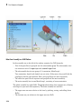
Watch a CAD Import Video . . . . . . . . . . . . . . . . . . . . . .
About the Example . . . . . . . . . . . . . . . . . . . . . . . . . . .
Watch the Example Video . . . . . . . . . . . . . . . . . . . . . .
Learn More About the Example . . . . . . . . . . . . . . . . .
1-11
1-11
1-11
1-12
1-2
1-2
1-7
v
2
vi
Contents
CAD Export
About CAD Translation . . . . . . . . . . . . . . . . . . . . . . . . . . .
Software Requirements . . . . . . . . . . . . . . . . . . . . . . . . .
CAD Export . . . . . . . . . . . . . . . . . . . . . . . . . . . . . . . . . .
CAD Import . . . . . . . . . . . . . . . . . . . . . . . . . . . . . . . . .
2-2
2-2
2-3
2-4
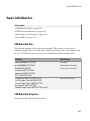
Export Robot CAD Assembly . . . . . . . . . . . . . . . . . . . . . .
CAD Files . . . . . . . . . . . . . . . . . . . . . . . . . . . . . . . . . . .
Platform-Specific Steps . . . . . . . . . . . . . . . . . . . . . . . . .
CAD Export Steps . . . . . . . . . . . . . . . . . . . . . . . . . . . . .
2-6
2-6
2-6
2-6
Export Stewart Platform CAD Assembly . . . . . . . . . . . .
CAD Files . . . . . . . . . . . . . . . . . . . . . . . . . . . . . . . . . . .
Example Requirements . . . . . . . . . . . . . . . . . . . . . . . . .
Platform-Specific Steps . . . . . . . . . . . . . . . . . . . . . . . . .
CAD Export Steps . . . . . . . . . . . . . . . . . . . . . . . . . . . . .
2-8
2-8
2-8
2-9
2-9
Guidelines for CAD Translation . . . . . . . . . . . . . . . . . .
How CAD Assemblies Are Translated into SimMechanics
Models . . . . . . . . . . . . . . . . . . . . . . . . . . . . . . . . . . .
Prepare CAD Assembly for Import into SimMechanics
Model . . . . . . . . . . . . . . . . . . . . . . . . . . . . . . . . . . .
2-10
Export and Re-Export CAD Assembly . . . . . . . . . . . . . .
About CAD Export . . . . . . . . . . . . . . . . . . . . . . . . . . .
Configure SimMechanics Link in Supported CAD
Platforms . . . . . . . . . . . . . . . . . . . . . . . . . . . . . . . . .
Generate Physical Modeling XML File . . . . . . . . . . . .
Re-Export Assembly After Changes . . . . . . . . . . . . . . .
Export Robot Arm Assembly . . . . . . . . . . . . . . . . . . . .
Re-Export a Robot Arm Assembly After Changes . . . .
2-15
2-15
2-10
2-12
2-15
2-17
2-17
2-18
2-19
Retranslate CAD Assembly . . . . . . . . . . . . . . . . . . . . . . .
Associativity and Updating . . . . . . . . . . . . . . . . . . . . .
Working with Associativity in Common Updating
Situations . . . . . . . . . . . . . . . . . . . . . . . . . . . . . . . .
2-20
2-20
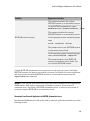
Troubleshoot CAD Export Issues . . . . . . . . . . . . . . . . . .
Unsupported Constraints . . . . . . . . . . . . . . . . . . . . . .
Use SimMechanics Link Help . . . . . . . . . . . . . . . . . . .
2-25
2-25
2-26
2-22
3
First-Generation Examples
Case Study Overview . . . . . . . . . . . . . . . . . . . . . . . . . . . . . . . .
Requirements . . . . . . . . . . . . . . . . . . . . . . . . . . . . . . . . . . . .
3-2
3-2
Export a CAD Rigid Body . . . . . . . . . . . . . . . . . . . . . . . . . . . . .
Access the Example Files . . . . . . . . . . . . . . . . . . . . . . . . . . .
Examine Rigid Body Parameters . . . . . . . . . . . . . . . . . . . . . .
Export CAD Rigid Body . . . . . . . . . . . . . . . . . . . . . . . . . . . .
Import CAD Rigid Body . . . . . . . . . . . . . . . . . . . . . . . . . . . .
3-4
3-4
3-4
3-6
3-6
Translate CAD Constraints into SimMechanics Joints . . . . .
Access the Example Files . . . . . . . . . . . . . . . . . . . . . . . . . . .
Translation of Two-Part Models . . . . . . . . . . . . . . . . . . . . . .
Block Structure of Two-Part Models . . . . . . . . . . . . . . . . . . .
Translate Assembly with Six-DoF Joint . . . . . . . . . . . . . . .
Translate Assembly with Prismatic Joint . . . . . . . . . . . . . .
Translate Assembly with Revolute Joint . . . . . . . . . . . . . . .
Translate Assembly with Rectangular Joint . . . . . . . . . . . .
Translate Assembly with Spherical-Spherical Massless
Connector . . . . . . . . . . . . . . . . . . . . . . . . . . . . . . . . . . . .
3-7
3-8
3-8
3-9
3-10
3-11
3-14
3-15
Export and Re-Export a Pendulum Assembly . . . . . . . . . . .
About Model Update . . . . . . . . . . . . . . . . . . . . . . . . . . . . . .
CAD Assembly Files . . . . . . . . . . . . . . . . . . . . . . . . . . . . . .
Translate CAD Assembly . . . . . . . . . . . . . . . . . . . . . . . . . .
Modify Pendulum Assembly and Update SimMechanics
Model . . . . . . . . . . . . . . . . . . . . . . . . . . . . . . . . . . . . . . .
Add New Body to Create a Triple Pendulum . . . . . . . . . . . .
Update Imported Model While Retaining Manual Joint
Replacements . . . . . . . . . . . . . . . . . . . . . . . . . . . . . . . . .
Selectively Update Imported Model . . . . . . . . . . . . . . . . . . .
3-19
3-19
3-19
3-20
Export CAD Robot Arm . . . . . . . . . . . . . . . . . . . . . . . . . . . . .
CAD Robot Arm Files . . . . . . . . . . . . . . . . . . . . . . . . . . . . .
CAD Robot Arm Properties . . . . . . . . . . . . . . . . . . . . . . . . .
Export Robot Arm Assembly . . . . . . . . . . . . . . . . . . . . . . . .
Import Model . . . . . . . . . . . . . . . . . . . . . . . . . . . . . . . . . . .
3-37
3-37
3-37
3-39
3-39
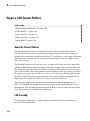
Export a CAD Stewart Platform . . . . . . . . . . . . . . . . . . . . . .
About the Stewart Platform . . . . . . . . . . . . . . . . . . . . . . . .
CAD Assembly . . . . . . . . . . . . . . . . . . . . . . . . . . . . . . . . . .
3-40
3-40
3-40
3-16
3-24
3-30
3-35
3-36
vii
Open Assembly . . . . . . . . . . . . . . . . . . . . . . . . . . . . . . . . . .
Export Assembly . . . . . . . . . . . . . . . . . . . . . . . . . . . . . . . . .
Import Model . . . . . . . . . . . . . . . . . . . . . . . . . . . . . . . . . . .
4
viii
Contents
3-41
3-42
3-42
Second-Generation Examples
Export Robot Assembly from SolidWorks Software . . . . . . .
Example Requirements . . . . . . . . . . . . . . . . . . . . . . . . . . . . .
Open Robot Assembly . . . . . . . . . . . . . . . . . . . . . . . . . . . . . .
Export CAD Assembly . . . . . . . . . . . . . . . . . . . . . . . . . . . . . .
Verify CAD Export Files . . . . . . . . . . . . . . . . . . . . . . . . . . . .
About the Example CAD Files . . . . . . . . . . . . . . . . . . . . . . .
About CAD Export . . . . . . . . . . . . . . . . . . . . . . . . . . . . . . . .
Export in First- and Second-Generation Formats . . . . . . . . .
4-2
4-3
4-4
4-4
4-5
4-5
4-6
4-6
Export Robot Assembly from Autodesk Inventor Software .
Example Requirements . . . . . . . . . . . . . . . . . . . . . . . . . . . . .
Open Robot Assembly . . . . . . . . . . . . . . . . . . . . . . . . . . . . . .
Export CAD Assembly . . . . . . . . . . . . . . . . . . . . . . . . . . . . . .
Check CAD Export Files . . . . . . . . . . . . . . . . . . . . . . . . . . .
About the Example CAD Files . . . . . . . . . . . . . . . . . . . . . .
About CAD Export . . . . . . . . . . . . . . . . . . . . . . . . . . . . . . .
4-7
4-8
4-9
4-9
4-10
4-10
4-11
Export Robot Assembly from Creo Software . . . . . . . . . . . .
Example Requirements . . . . . . . . . . . . . . . . . . . . . . . . . . . .
Open Robot Assembly . . . . . . . . . . . . . . . . . . . . . . . . . . . . .
Export CAD Assembly . . . . . . . . . . . . . . . . . . . . . . . . . . . . .
Verify CAD Export Files . . . . . . . . . . . . . . . . . . . . . . . . . . .
About the Example CAD Files . . . . . . . . . . . . . . . . . . . . . .
About CAD Export . . . . . . . . . . . . . . . . . . . . . . . . . . . . . . .
Export in First- and Second-Generation Formats . . . . . . . .
4-12
4-13
4-13
4-14
4-15
4-16
4-17
4-17
Export Stewart Platform from SolidWorks Software . . . . .
Example Requirements . . . . . . . . . . . . . . . . . . . . . . . . . . . .
Open Robot Assembly . . . . . . . . . . . . . . . . . . . . . . . . . . . . .
Export CAD Assembly . . . . . . . . . . . . . . . . . . . . . . . . . . . . .
Verify CAD Export Files . . . . . . . . . . . . . . . . . . . . . . . . . . .
About the Example CAD Files . . . . . . . . . . . . . . . . . . . . . .
About CAD Export . . . . . . . . . . . . . . . . . . . . . . . . . . . . . . .
4-18
4-19
4-20
4-20
4-21
4-22
4-23
Export Stewart Platform from Creo Software . . . . . . . . . . .
Example Requirements . . . . . . . . . . . . . . . . . . . . . . . . . . . .
Open Robot Assembly . . . . . . . . . . . . . . . . . . . . . . . . . . . . .
Export CAD Assembly . . . . . . . . . . . . . . . . . . . . . . . . . . . . .
Verify CAD Export Files . . . . . . . . . . . . . . . . . . . . . . . . . . .
About the Example CAD Files . . . . . . . . . . . . . . . . . . . . . .
About CAD Export . . . . . . . . . . . . . . . . . . . . . . . . . . . . . . .
Export in First- and Second-Generation Formats . . . . . . . .
5
4-24
4-25
4-26
4-26
4-27
4-28
4-29
4-29
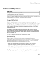
Custom Linking to Third-Party Applications
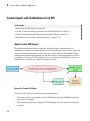
Custom Export with SimMechanics Link API . . . . . . . . . . . .
About Custom CAD Export . . . . . . . . . . . . . . . . . . . . . . . . . .
Custom Translation Steps in Common with Standard Export
Custom Translation Steps Different from Standard Export . .
Requirements for Creating a Custom Exporter . . . . . . . . . . .
5-2
5-2
5-3
5-3
5-4
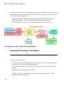
Custom Translation into Physical Modeling XML Format . .
About Mapping API Objects from CAD Format to Physical
Modeling XML . . . . . . . . . . . . . . . . . . . . . . . . . . . . . . . . .
Selecting CAD Assembly Data for Export . . . . . . . . . . . . . . .
Constructing Intermediate API Representations . . . . . . . . . .
Converting Selective API Representations into Physical
Modeling XML . . . . . . . . . . . . . . . . . . . . . . . . . . . . . . . . .
5-6
5-6
5-8
5-8
5-10
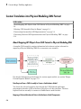
Design Custom Exporter Module . . . . . . . . . . . . . . . . . . . . . .
Prerequisites for Custom Exporter Modules . . . . . . . . . . . .
Implementing Translation with CAD and SimMechanics Link
APIs . . . . . . . . . . . . . . . . . . . . . . . . . . . . . . . . . . . . . . . .
5-11
5-11
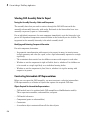
Program Custom Exporter with SimMechanics Link API .
Including, Linking to, and Calling the API Function Library
Locating API Code Examples . . . . . . . . . . . . . . . . . . . . . . .
A Custom Exporter Module Example . . . . . . . . . . . . . . . . .
5-15
5-15
5-16
5-16
5-12
ix
Getting Started
1
Introduction to SimMechanics Link
Software
• “Product Description” on page 1-2
• “Related Products” on page 1-4
• “Install and Register SimMechanics Link Software” on page 1-6
• “Watch a CAD Import Video” on page 1-11
1
Introduction to SimMechanics Link Software
Product Description
In this section...
“Product Definition” on page 1-2
“Using SimMechanics Link and SimMechanics Software Together for Complete CAD
Translation” on page 1-2
Product Definition
Computer-aided design (CAD) is an integral part of engineering design in many
industries. CAD tools allow engineers to model their mechanical systems in 3-D space.
Although this approach is excellent for geometric modeling, incorporating controllers
into this environment is difficult. Simulink® with SimMechanics software uses a
block-diagram schematic approach for modeling control systems around mechanical
devices. The SimMechanics Link utility bridges the gap between geometric modeling
and block diagram modeling and simulation, by combining the power of Simulink and
SimMechanics software with CAD.
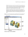
Using SimMechanics Link and SimMechanics Software Together for
Complete CAD Translation
Tip For a video example of how CAD import works, see “Watch a CAD Import Video” on
page 1-11 .
With the SimMechanics Link utility, you can create a SimMechanics model from a CAD
assembly, in two steps.
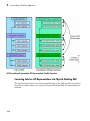
Exporting CAD Assemblies Into Physical Modeling XML
The first translation step is to use the SimMechanics Link exporter to create an
intermediate Physical Modeling XML file from a CAD assembly. Using SimMechanics
software, you can then import that XML file to automatically generate a SimMechanics
model.
With SimMechanics Link export, you initiate the translation of CAD assemblies into
dynamical block diagram models. You export:
1-2
Product Description
• CAD assemblies into Physical Modeling XML format. The XML file captures the mass
and inertia of each part in the assembly and the constraint definitions between parts.
• Graphics files to define the body geometries of the assembly parts. The graphics files
capture the body geometries of the assembly parts.
Importing Physical Modeling XML to Generate SimMechanics Models
The second translation step is to import the Physical Modeling XML to generate the
SimMechanics model, then use that model together with the body geometry graphics files
to simulate and visualize the original mechanical system.
• The XML representations of parts and constraints become bodies and joints in a
SimMechanics model.
• The generated SimMechanics model uses the exported body geometry graphics files to
visualize the bodies.
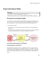
Creating a Custom Link using the SimMechanics Link API
For CAD platforms not directly supported, you can use the SimMechanics Link API
to connect to your CAD platform API. You create a custom export link that achieves
the same export results as for supported CAD platforms, export of the XML and body
geometry files.
1-3
1
Introduction to SimMechanics Link Software
Related Products
In this section...
“Required Products” on page 1-4
“Other Related Products” on page 1-4
Required Products
SimMechanics Link software requires MATLAB® software.
Supported Operating Systems
You can use the SimMechanics Link product on any operating system that supports
MATLAB.
Supported CAD Platforms
To build and export CAD assemblies, you need a CAD platform. Such a platform must
either be supported directly by the SimMechanics Link utility or have an API you can use
to write a custom SimMechanics Link interface.
Other Related Products
SimMechanics Product
Note: The SimMechanics Link utility does not require the SimMechanics, Simscape™, or
Simulink products.
The Physical Modeling XML and body geometry graphics files exported by the
SimMechanics Link utility are intended for use with the SimMechanics product.
Physical Modeling Product Family
Use the Physical Modeling product family to model physical systems in Simulink. In
addition to SimMechanics software, it includes:
• Simscape the platform and unifying environment for Physical Modeling products
1-4
Related Products
• SimDriveline™ for modeling and simulating drivetrain systems
• SimElectronics® for modeling and simulating electronic systems
• SimHydraulics® for modeling and simulating hydromechanical systems
• SimPowerSystems™ for modeling and simulating electrical power systems
1-5
1
Introduction to SimMechanics Link Software
Install and Register SimMechanics Link Software
In this section...
“Installation Requirements” on page 1-6
“Download SimMechanics Link Software” on page 1-6
“Install SimMechanics Link Software” on page 1-7
“Register SimMechanics Link Utility with CAD Platform” on page 1-7
“Link External Application to SimMechanics Link Software” on page 1-8
“Register MATLAB as Automation Server” on page 1-8
“Unregister SimMechanics Link Software” on page 1-10
Installation Requirements
Before installing the SimMechanics Link utility, check that an active installation of the
following software exists on your computer:
• MATLAB
• Supported CAD platform
MATLAB and SimMechanics Link must belong to the same release. For example, if your
MATLAB release is R2014b, then your SimMechanics Link release must also be R2014b.
Combining different release numbers can cause installation errors.
SimMechanics Link supports three CAD platforms:
• SolidWorks®
• Autodesk Inventor®
• PTC® Creo™ (formerly Pro/ENGINEER®)
You can use the SimMechanics Link utility to export a CAD assembly from any of these
CAD platforms. Note that MATLAB, SimMechanics Link, and your CAD platform must
share the same architecture (e.g. 64-bit).
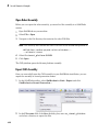
Download SimMechanics Link Software
You can download SimMechanics Link software directly from the MathWorks® website:
1-6
Install and Register SimMechanics Link Software
1
Visit the SimMechanics Link download website at http://www.mathworks.com/
products/simmechanics/download_smlink.html.
2
Select the software version to install.
3
Click Submit.
4
Save the installation files in a convenient folder.
Do not extract the zip file.
Install SimMechanics Link Software
Install SimMechanics Link software from the MATLAB command line:
1
Start MATLAB.
Note: You may need administrator privileges to complete the installation.
2
At the MATLAB command line enter:
path(path, '<installation_file_folder>')
replacing <installation_file_folder> with the path to the folder with the
installation files.
3
At the MATLAB command line, enter:
install_addon('<zip_file_name>.zip')
replacing <zip_file_name> with the name of the zip file that you downloaded (e.g.,
smlink.r2014b.win64). The command extracts the zip archive files to the MATLAB
root directory.
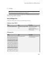
Register SimMechanics Link Utility with CAD Platform
Complete the installation by registering the SimMechanics Link utility with your CAD
platform. The registration procedure makes SimMechanics Link available in your CAD
platform as an Add-In tool. Once you have completed the linking procedure, you can use
the Add-In tool to export a CAD assembly directly from your CAD platform.
The registration procedure is different for each supported CAD platform. The following
table provides platform-specific registration information. Click the link that matches
your CAD platform, and complete the registration procedure.
1-7
1
Introduction to SimMechanics Link Software
To register with CAD platform...
...Click here
Autodesk Inventor
“Enable SimMechanics Link Inventor PlugIn”
PTC Creo (Pro/ENGINEER)
“Enable SimMechanics Link Creo-Pro/E
Plug-In”
SolidWorks
“Enable SimMechanics Link SolidWorks
Plug-In”
Link External Application to SimMechanics Link Software
You can link an unsupported CAD platform or other external application to
SimMechanics software. For this task, SimMechanics Link provides an application
programming interface (API) with a set of functions that you can use to create a C/C+
+ custom export module. For an overview of custom export using the API, see “Custom
Export with SimMechanics Link API”.
Register MATLAB as Automation Server
Each time you use the SimMechanics Link utility with a CAD platform or other external
application, the utility attempts to connect to MATLAB.
Registration Requirements
Successful connection requires the following to be true:
• Matching MATLAB and SimMechanics Link release numbers (e.g. both release
numbers R2014b)
• MATLAB registration as automation server.
Enable Automation Server Mode
You can register MATLAB as an automation server in two ways:
1-8
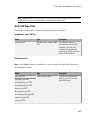
Condition
Registration Procedure
MATLAB session open in desktop mode
At the MATLAB command line, enter
regmatlabserver.
Install and Register SimMechanics Link Software
Condition
Registration Procedure
The command registers the current
MATLAB session as an automation server.
At the MATLAB command line, enter
enableservice('AutomationServer',true).
The command enables the current
MATLAB session as an automation server.
MATLAB session not open
At the operating system command prompt,
enter
matlab -automation -desktop
The prompt starts a new MATLAB session
in automation server mode.
At the operating system command prompt,
enter command matlab -regserver.
The command opens a new MATLAB
session in automation server mode. You
can close the MATLAB session.
A single MATLAB automation server registration can be active at a time. If multiple
MATLAB sessions are open in your system, you must first disable the active registration
and then register the desired MATLAB session as an automation server using the
regmatlabserver command.
Caution If your system does not have an active MATLAB automation server registration,
SimMechanics Link issues a error when it attempts to connect. In the event of a
connection error, check that a MATLAB automation server is active in your system. If
necessary, register MATLAB as an automation server.
Connection from External Application to MATLAB Automation Server
Invoking the SimMechanics Link utility from an external application produces one of the
following results:
1-9
1
Introduction to SimMechanics Link Software
Condition
Required Action
Result
No MATLAB session open
None
• New MATLAB session
opens in automation
server mode
• SimMechanics Link
connects to MATLAB
automation server
MATLAB server open in
automation server mode
None
• SimMechanics Link
connects to MATLAB
automation server
MATLAB session open in
desktop mode
Register MATLAB session • SimMechanics Link
as automation server. See
connects to MATLAB
“Enable Automation Server
automation server
Mode” on page 1-8.
Unregister SimMechanics Link Software
SimMechanics Link contains no uninstaller. If you no longer wish to use the
SimMechanics Link utility in your CAD platform, you can unregister the utility. The
following table provides information on the unlinking procedure for each CAD platform.
Click the link that matches your CAD platform.
To link CAD platform...
...click here
Autodesk Inventor
“Enable SimMechanics Link Inventor PlugIn”
PTC Creo (Pro/ENGINEER)
“Enable SimMechanics Link Creo-Pro/E
Plug-In”
SolidWorks
“Enable SimMechanics Link SolidWorks
Plug-In”
To register a different version of SimMechanics Link with your CAD platform, first
unregister any currently registered version you may have. Then, register the desired
version. To register and unregister the utility, follow the links provided in the previous
table.
1-10
Watch a CAD Import Video
Watch a CAD Import Video
In this section...
“About the Example” on page 1-11
“Watch the Example Video” on page 1-11
“Learn More About the Example” on page 1-12
About the Example
The example consists of a series of steps that:
• Start with a CAD assembly.
• Show how, with SimMechanics Link and SimMechanics software, to translate the
assembly into a SimMechanics model through export and import.
• Show how to modify the original assembly, then reexport and reimport it with
successive changes that modify the imported model.
• Show how to manually modify the initial generated model, then update it with
changes to the original assembly, without losing your manual changes to the model.
The assembly models a double pendulum, subsequently modified to a triple pendulum.
What the Example Requires
The complete procedure requires the original CAD assembly and platform, as well as
SimMechanics Link and SimMechanics software.
Watch the Example Video
A video of the example is available at the MathWorks Web site, www.mathworks.com. If
you are reading this in a browser and have access to the Internet, click here to access the
example page.
What the Video Requires
The video requires a Web browser with a compatible streaming video application.
1-11
1
Introduction to SimMechanics Link Software
Learn More About the Example
The example video performs the steps of the case study, Updating and Retranslating a
CAD Pendulum.
1-12
2
CAD Export
The SimMechanics Link exporter allows you to translate a machine defined externally
(such as a computer-aided design assembly) into an intermediate representation. From
this intermediate representation, you can generate a SimMechanics model representing
the original machine and simulate its motion in the Simulink environment. The
intermediate representation allows you to separate the export of external machine data
with the SimMechanics Link utility and the generation of the dynamic model with the
SimMechanics importer.
• “About CAD Translation” on page 2-2
• “Export Robot CAD Assembly” on page 2-6
• “Export Stewart Platform CAD Assembly” on page 2-8
• “Guidelines for CAD Translation” on page 2-10
• “Export and Re-Export CAD Assembly” on page 2-15
• “Retranslate CAD Assembly” on page 2-20
• “Troubleshoot CAD Export Issues” on page 2-25
2
CAD Export
About CAD Translation
In this section...
“Software Requirements” on page 2-2
“CAD Export” on page 2-3
“CAD Import” on page 2-4
CAD translation is a modeling process that converts a CAD assembly into a
SimMechanics model. The complete process contains two sequential steps:
1
CAD Export — The SimMechanics Link utility generates an import file. The file
reflects assembly structure and contains part parameters.
2
CAD Import — SimMechanics interprets the import file and generates a new model.
The model structure and part parameters mirror the original CAD assembly.
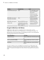
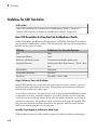
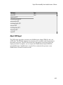
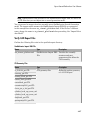
Software Requirements
The complete CAD translation process requires the following software.
2-2
Software
Notes
CAD Export
CAD Import
CAD Platform
✓
MATLAB
Registration as
computing server
required
✓
About CAD Translation
Software
Notes
CAD Export
CAD Import
SimMechanics
✓
SimMechanics Link
✓
Note: CAD Export does not require SimMechanics, Simscape, or Simulink products.
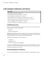
CAD Export
CAD export relies on the free utility SimMechanics Link. You can download the utility
directly from the Mathworks website. See “Install and Register SimMechanics Link
Software”. Following download and installation, registration of SimMechanics Link with
a supported CAD platform adds the utility as an Add-In tool. You can now export a CAD
assembly.
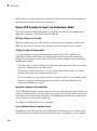
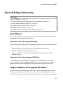
During CAD export, the SimMechanics Link utility generates one XML file and a set of
STL files. The following table describes each file type.
File Type
Quantity
Purpose
Required for
Required
Model Generation for Model
Visualization
XML
1 total
Provide
structure and
parameters
of CAD
assembly in
SimMechanics
format
✓
STL
1 per distinct
CAD part
Provide 3D surface
geometry of
CAD parts
✓
The files contain the assembly structure and part parameters required to generate an
equivalent SimMechanics model. Assembly structure includes assembly-subassembly
dependencies, which translate into SimMechanics system-subsystem dependencies. Part
parameters include reference frames, mass and inertia, color, and location of part STL
files.
2-3
2
CAD Export
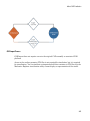
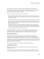
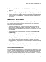
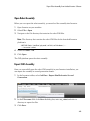
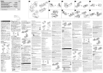
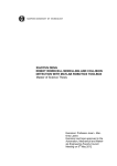
CAD Export Process
CAD Import
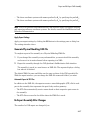
CAD import is the second and final step of CAD translation. During CAD import,
SimMechanics interprets the XML import file and automatically generates the
corresponding model. SimMechanics imports CAD parts as rigid bodies, and CAD
constraints as joints. The set of STL files provide the 3-D surface geometry of each
SimMechanics rigid body.
2-4
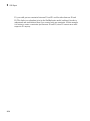
About CAD Translation
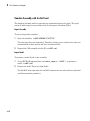
CAD Import Process
CAD Import does not require access to the original CAD assembly or associated CAD
platform.
Access to the surface-geometry STL files is not required for simulation, but it is required
for visualization. You can simulate an imported model that contains no STL files, but the
Mechanics Explorer visualization utility cannot display a representation of the model.
2-5
2
CAD Export
Export Robot CAD Assembly
In this section...
“CAD Files” on page 2-6
“Platform-Specific Steps” on page 2-6
“CAD Export Steps” on page 2-6
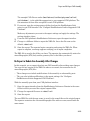
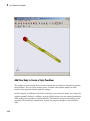
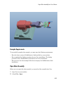
This example guides you through the export procedure for a CAD assembly with name
sm_robot.xml. The assembly models an industrial robot arm that contains a grip
subassembly.
CAD Files
Required CAD files are present in your SimMechanics Link installation. You can access
the files in the following directory:
matlabroot\toolbox\physmod\smlink\smlinkdemos\robot
where matlabroot is the directory of your MATLAB installation (for example, c:
\program files\MATLAB\R2012b.
Platform-Specific Steps
The procedure in this example is general and applicable to all supported CAD platforms.
For platform-specific steps, click the appropriate link in the following table.
For CAD platform...
...click here
Autodesk Inventor
“Export Robot Assembly from Autodesk
Inventor Software” on page 4-7
PTC Creo
“Export Robot Assembly from Creo
Software” on page 4-12
SolidWorks
“Export Robot Assembly from SolidWorks
Software” on page 4-2
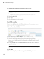
CAD Export Steps
Complete the following steps to export the robot CAD assembly in second-generation
format. The procedure generates one SimMechanics Import XML file and a set of STL
2-6
Export Robot CAD Assembly
geometry files. Import the files into SimMechanics to generate a model that replicates
the CAD assembly.
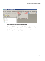
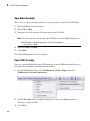
1
In a supported CAD platform, open assembly file sm_robot.
2
On the CAD menu bar, click SimMechanics Link.
3
Select Export into SimMechanics First Generation or Export into
SimMechanics Second Generation.
4
In the Save As dialog box, enter the export file name and click OK.
2-7
2
CAD Export
Export Stewart Platform CAD Assembly
In this section...
“CAD Files” on page 2-8
“Example Requirements” on page 2-8
“Platform-Specific Steps” on page 2-9
“CAD Export Steps” on page 2-9
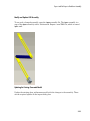
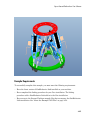
This example guides you through the export procedure for a CAD assembly with name
stewart_platform.xml. The assembly models a Stewart platform commonly used in
flight-simulator systems.
CAD Files
Required CAD files are present in your SimMechanics Link installation. You can access
the files in the following directory:
matlabroot\toolbox\physmod\smlink\smlinkdemos\...
...<cad_platform>\stewart
String matlabroot is the directory of your matlab installation (for example, c:
\program files\MATLAB\R2012b. String <cad_platform> is one of two CAD
platforms that contain the Stewart Platform example:
• Creo (Pro/ENGINEER)
• SolidWorks
Example Requirements
To successfully complete the example, you must have:
• Supported CAD platform
• MATLAB installation, registered as an automation server. See “Register MATLAB as
Automation Server” on page 1-8.
• SimMechanics Link installation, registered with the appropriate CAD platform.
2-8
To link to...
See...
Creo (Pro/ENGINEER)
“Enable SimMechanics Link Creo-Pro/E
Plug-In”
Export Stewart Platform CAD Assembly
To link to...
See...
SolidWorks
“Enable SimMechanics Link SolidWorks
Plug-In”
Platform-Specific Steps
The procedure in this example is general and applicable to all supported CAD platforms.
For platform-specific steps, click the appropriate link in the following table.
For CAD platform...
...click here
PTC Creo
“Export Stewart Platform from Creo
Software” on page 4-24
SolidWorks
“Export Stewart Platform from SolidWorks
Software” on page 4-18
CAD Export Steps
Complete the following steps to export the robot CAD assembly in second-generation
format. The procedure generates one SimMechanics Import XML file and a set of STL
geometry files. Import the files into SimMechanics to generate a model that replicates
the CAD assembly.
1
In a supported CAD platform, open assembly file stewart_platform.
2
In the CAD menu bar, click SimMechanics Link.
3
Select Export into SimMechanics First Generation or Export into
SimMechanics Second Generation.
4
In the Save As dialog box, enter the file name and click OK.
2-9
2
CAD Export
Guidelines for CAD Translation
In this section...
“How CAD Assemblies Are Translated into SimMechanics Models” on page 2-10
“Prepare CAD Assembly for Import into SimMechanics Model” on page 2-12
How CAD Assemblies Are Translated into SimMechanics Models
During CAD export, SimMechanics Link generates an XML file that maps CAD entities
onto equivalent SimMechanics entities. The following table indicates the correspondence
between the two types of entities.
CAD Entity
SimMechanics First Generation Equivalent
Part
Body
Constraints (Mates)
Joint
Reference coordinate system
Unconnected coordinate system ports
Assembly Reference
Fundamental Root: Root Ground — Weld – Root
Part
Subassembly
Subsystem
Subassembly Reference
Root Part
Fixed Part
Root Body – Weld – Body
Origins, References, Roots, and Root Bodies
Every CAD assembly has a single assembly origin and one or more assembly references
that do not move with respect to the origin. The positions and orientations of all parts
refer directly or indirectly to this origin.
A root body is a zero-mass, zero-inertia body used in the generated SimMechanics model
to represent one or more assembly references. A root body is always welded to ground,
so that its zero mass and zero inertia do not affect the model's dynamics. A root body is
necessary to represent a fixed anchor for part constraints in the original assembly. This
body can carry multiple coordinate systems for this purpose, while the single Ground
block in the generated model can carry only one.
Assembly Origin Mapped to SimMechanics World Origin
CAD translation maps the CAD assembly origin to the World coordinate system origin.
2-10
Guidelines for CAD Translation
Subassemblies and Hierarchies
You can isolate a collection of CAD components (parts and their constraints) into a
subassembly. CAD translation converts subassemblies into SimMechanics subsystems.
The main assembly is like the trunk of a tree, and its subassemblies are like the
branches of the tree. Subassemblies can have subassemblies, and so on. This tree is
the assembly's hierarchy. Each CAD subassembly has its own subassembly origin and
references. A fixed part of a CAD subassembly is a part that is welded to a subassembly
reference. It cannot move relative to the subassembly origin.
For an example of subassembly hierarchy, see “Export CAD Robot Arm”.
Mass Properties of Assembly Parts
The CAD assembly's parts need to have masses and inertia tensors. When you generate
the SimMechanics model, this mass property information is used to specify the properties
of the SimMechanics Body block corresponding to each assembly part.
Constraint Geometries
The constraints in your CAD assembly restrict how the assembly's parts can move with
respect to each other. Without any constraints, a pair of CAD parts can move with six
unrestricted degrees of freedom (DoFs) relative to one another. Constraints between
pairs of parts reduce the six to fewer DoFs. SimMechanics joints express DoFs between
bodies because SimMechanics bodies by themselves carry no DoFs. CAD constraints and
SimMechanics joints are complements of one another.
Each joint is connected to two bodies, each at a body coordinate system (CS). The
constraint geometry determines the joints into which CAD export translates the
constraints and controls the position and orientation of the body CSs. Each of these body
CSs has an origin and axis triad fixed relative to its body. CAD translation creates body
CSs on the bodies, as necessary, for connecting joints.
Reference Coordinate Systems
Your CAD assembly can contain reference coordinate systems inserted on parts or
elsewhere in the assembly. In general, these coordinate systems are not associated with
constraints.
Export of such reference coordinate systems is optional. If these coordinate systems
are translated into a SimMechanics model, they appear as coordinate systems on Body
2-11
2
CAD Export
blocks, but not associated with Joint connections. When the model is initially imported,
the reference coordinate systems are unconnected.
Prepare CAD Assembly for Import into SimMechanics Model
You need to specify enough information in your CAD assembly for the SimMechanics
importer to construct a valid model from the XML file.
CAD Export Requires an Assembly
When you export from your CAD platform, you must export a complete assembly into
XML, not just a part. If you have only one part, you must embed it in an assembly.
Simplify Assembly with Subassemblies
Use subassemblies to organize your assembly hierarchically. This simplifies your
subsequent SimMechanics model by grouping blocks into corresponding subsystems.
Follow these guidelines to ensure that your CAD assembly translates into a functioning
SimMechanics model:
• You must have at least one fixed part inside each subassembly. For more about fixed
parts, see “Subassemblies and Hierarchies”.
• Put as many welded components as you can inside rigid subassemblies or combine
welded components into a single equivalent part.
If your assembly has a group of parts that do not move relative to one another, model
them as a single part, eliminating unnecessary Body and Joint blocks from the
generated SimMechanics model.
Specify Mass Properties of Assembly Parts
Your CAD platform might compute masses and inertia values from the mass density and
geometry of the assembly parts. Otherwise, you must specify the mass and inertia tensor
with respect to the part's center of gravity. The SimMechanics Link utility computes the
center of gravity of each part automatically.
See “Export a CAD Rigid Body” for an example.
Insert and Name Reference Coordinate Systems
Depending on your CAD platform and SimMechanics Link interface, you might be able
to insert reference coordinate systems on assembly parts or elsewhere in your assembly.
2-12
Guidelines for CAD Translation
If you choose to export these coordinate systems, translation creates corresponding
unattached Body coordinate systems in the generated SimMechanics model. You control
the selective export of these reference coordinate systems by giving names with a
distinctive prefix to these coordinate systems.
You can use reference coordinate systems in several ways.
• Prepare a CAD assembly for manual addition or replacement of Joints after import.
These manually added Joints are independent of Joints automatically generated from
assembly constraints.
Some CAD constraints are not supported for export. When you translate an assembly
into a model, constraints that fail to translate into moving Joint blocks appear as rigid
Welds. To represent your assembly correctly requires manual replacement of these
Welds with moving Joints.
• Prepare a CAD assembly for manual addition of Constraints, Drivers, Actuators,
and Sensors after import. To attach these blocks to Bodies, you need additional Body
coordinate systems, apart from the Body coordinate systems automatically generated
to connect Joints representing assembly constraints.
You might find it easier to prepare for manually adding Joints, Constraints, Drivers,
Actuators, and Sensors by setting up reference coordinate systems before export and
attaching these Body coordinate systems to manually added blocks after import.
Specify Constraint Geometries
You must specify the constraint geometry in the CAD assembly consistently and in
enough detail to reconstruct the assembly's DoFs as joints. The relationship between
constraints in CAD and SimMechanics joints is not, in general, a simple mapping. Some
SimMechanics joints have only one DoF, while others represent more than one DoF. CAD
translation often combines multiple DoFs into one joint. Constraint specification details
depend on the specific CAD platform.
For an example of configuring constraints, see “Export CAD Robot Arm”.
Avoid Redundant Constraints
Keep constraints simple and few enough to avoid creating unnecessary joints in your
SimMechanics model.
For example, consider three parts, P1, P2, and P3, in an assembly. Suppose P1 and P2
are constrained so that there is no movement possible between them. When you attach
2-13
2
CAD Export
P3, you could put one constraint between P3 and P1 and the other between P3 and
P2. This leads to a redundant joint in the SimMechanics model, making it harder to
understand and troubleshoot than if you created only one constraint. In this example,
it is better to create a constraint just between P3 and P2, since P2 cannot move with
respect to P1 anyway.
2-14
Export and Re-Export CAD Assembly
Export and Re-Export CAD Assembly
In this section...
“About CAD Export” on page 2-15
“Configure SimMechanics Link in Supported CAD Platforms” on page 2-15
“Generate Physical Modeling XML File” on page 2-17
“Re-Export Assembly After Changes” on page 2-17
“Export Robot Arm Assembly” on page 2-18
“Re-Export a Robot Arm Assembly After Changes” on page 2-19
About CAD Export
This section explains at a high level how to export CAD assemblies from CAD platforms
supported by the SimMechanics Link utility.
Requirements for Export with a Supported CAD Platform
The SimMechanics Link Reference documentation presents platform-specific information
on:
• Linking a supported CAD platform with the SimMechanics Link utility
• Finding, changing, and applying export settings
• Exporting assemblies in the Physical Modeling XML format through the CAD
platform interface
Requirements for Export with an Unsupported CAD Platform
If the SimMechanics Link utility does not support your CAD platform, you can still
export assemblies to Physical Modeling XML. In this case, must construct a custom
exporter that utilizes the SimMechanics Link application program interface (API).
Configure SimMechanics Link in Supported CAD Platforms
Once it is linked to the SimMechanics Link utility, each CAD platform's interface has a
SimMechanics Link menu that allows you to access the export settings pane or dialog
box. Before you export an assembly, you can check, change, and apply the export settings.
2-15
2
CAD Export
Open Settings Pane or Dialog Box
1
Open your CAD assembly.
2
From the CAD platform's SimMechanics Link menu, open the settings interface.
At any time, you can:
• Apply your settings.
• Cancel your settings. You lose whatever new settings you have entered.
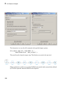
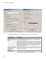
Configure Export Tolerances
In the settings interface, you can configure one or more of the export tolerances.
Geometric and numerical differences smaller than the tolerances are treated as zero.
• Linear tolerance specifies the smallest significant difference in length.
• Angular tolerance specifies the smallest significant difference in angle.
• Relative roundoff specifies the smallest significant numerical difference.
Configure Reference Coordinate Systems for Export
In the export coordinate systems interface, you can require the export of all, some, or
none of the reference coordinate systems in your assembly. You control selective export
by adding a distinctive prefix to the names of assembly coordinate systems that you want
to export.
• You can export all the reference coordinate systems by choosing export and specifying
no prefix.
• You can export some of the reference coordinate system by choosing export and
specifying a prefix. Reference coordinate systems labeled by names with that prefix
are exported.
• You can also choose not to export any reference coordinate systems.
For example, if your assembly has 11 reference coordinate systems (five with names
beginning with A_, three with names beginning with B_, and three with names beginning
with C_), you can choose to export:
• All 11 coordinate systems by specifying no prefix.
• The five coordinate systems with names prefixed by A_ by specifying the prefix A_.
2-16
Export and Re-Export CAD Assembly
• The three coordinate systems with names prefixed by B_ by specifying the prefix B_.
• The three coordinate systems with names prefixed by C_ by specifying the prefix C_.
Note: Your CAD platform and SimMechanics Link interface might not support inserting
and exporting reference coordinate systems. For details, consult the SimMechanics Link
Reference Documentation.
Apply Export Settings
Apply your export settings by clicking the OK button in the settings pane or dialog box.
The settings interface closes.
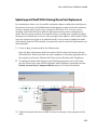
Generate Physical Modeling XML File
To complete export of the assembly to a Physical Modeling XML file:
1
If you changed the assembly or any subassemblies, you must rebuild the assembly
and resave it in its native format before exporting it to XML.
2
Export the assembly through the CAD platform's SimMechanics Link interface.
The assembly is saved in a new form as an XML file. The exporter displays a dialog
box when it is finished.
The default XML file name and folder are the same as those of the CAD assembly file.
With the export interface, you can change the XML file name and folder if you want.
Automatic Export of STL Files
In addition to the XML file, the exporter creates a stereolithographic (STL) file for each
part in the assembly that represents the part's body surface geometry.
• The STL files automatically receive names based on their respective part names in
the assembly.
• The STL files are saved in the folder where the XML file is saved.
Re-Export Assembly After Changes
The results of a CAD export are changed if you:
2-17
2
CAD Export
• Change the assembly or any of its subassemblies or parts
• Change the export settings. See “Configure SimMechanics Link in Supported CAD
Platforms”.
Re-exporting an assembly after such changes is, by default, identical to the initial export
steps. See “Generate Physical Modeling XML File”. With no changes to the XML file
save procedure, your re-export overwrites the existing XML and STL files with the same
names.
Tip For later use and comparison, you might want to preserve the older XML and STL
files.
• You can use the old folder and give the re-exported XML file a new name. The
exporter still overwrites the old STL files.
• You can use a new folder and avoid overwriting any old files.
Consequences of Re-Exporting Assemblies for Generated Models
While the re-export procedure is the same as, or only slightly different from, the
initial export, the resulting new Physical Modeling XML file represents a revised CAD
assembly, not a new assembly. To import this XML file with the SimMechanics importer
requires choosing how to implement the revisions:
• Create a new SimMechanics model
• Update an existing generated SimMechanics model
You can make more detailed adjustments to the second choice as well, using the
persistent properties that the XML file retains when you revise and re-export an existing
assembly. See “Retranslate CAD Assembly”.
Export Robot Arm Assembly
In this example, you export a CAD assembly for the first time into Physical Modeling
XML.
1
2-18
From the SimMechanics Link demos folder, open the robot arm assembly file,
robot.ASSEMBLYFILETYPE, using a supported CAD platform linked to the
SimMechanics Link utility.
Export and Re-Export CAD Assembly
The example CAD files are under $matlabroot/toolbox/physmod/smlink/
smlinkdemos/, in the subfolder appropriate to your supported CAD platform. The
file extensions of these files are specific to each CAD platform.
2
If you want, open the settings pane or dialog box from the SimMechanics Link
menu in your CAD interface. See “Configure SimMechanics Link in Supported CAD
Platforms”.
Make any adjustments you want to the export settings and apply the settings. The
settings interface closes.
3
From the CAD platform's SimMechanics Link menu, open the export interface.
4
Change to a different folder to export the XML file. Leave the file name as the
default, robot.xml.
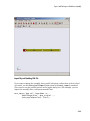
5
Start the export. The exporter begins converting and saving the XML file. When
export is complete, a message appears notifying you of export completion.
The XML file is saved to the folder you chose. The exporter also automatically writes the
stereolithographic (STL) body surface geometry files to the folder you choose.
Re-Export a Robot Arm Assembly After Changes
In this example, you re-export the robot arm CAD assembly after making some changes.
You save the new version of the XML file under a new name, but overwrite the old
stereolithographic (STL) files.
• These changes can include modifications of the assembly or subassembly parts.
• They can also include modifications to the export settings. See “Configure
SimMechanics Link in Supported CAD Platforms”.
With the assembly open from your CAD platform interface:
1
Open the export interface from the SimMechanics Link menu. Remain in the same
folder in which you saved the original exported files.
2
Change the exported file name to robot1.xml.
3
Start the export.
The new XML file, with the new name, is saved in the same folder as the original export.
The exporter overwrites the old stereolithographic files with new ones, named with the
same names.
2-19
2
CAD Export
Retranslate CAD Assembly
In this section...
“Associativity and Updating” on page 2-20
“Working with Associativity in Common Updating Situations” on page 2-22
Associativity and Updating
To update an existing generated SimMechanics model with changes to its original
external definition (a CAD assembly, for example), the intermediate Physical Modeling
XML file and the model itself must retain information about the identities of at least
some of its components. This section explains this “identity memory” or associativity.
What Is Associativity?
Associativity is a key concept for understanding the relationship between CAD
assemblies and SimMechanics models based on them, and the export and updating
process that defines SimMechanics models from CAD assemblies.
Associativity Between CAD Assemblies and SimMechanics Models
Associativity is a persistent (session-independent) parallel relationship among certain
components of a CAD assembly, Physical Modeling XML files exported from it, and
SimMechanics models generated from the XML files.
This relationship preserves the identities and parallelisms of certain CAD components
and the corresponding imported components of the SimMechanics model. The
SimMechanics Link exporter defines these unique identities from the CAD assembly
components and embeds them in the exported Physical Modeling XML file.
SimMechanics models generated from the XML file in turn retain these identities.
You actualize associativity when you generate a SimMechanics model from a CAD
assembly. Associativity is a mapping between parts, constraints, and subassemblies in
a CAD assembly and the corresponding Body and Joint blocks, coordinate systems, and
subsystems in the SimMechanics model generated from that CAD assembly. It uniquely
captures the identities of these CAD components, their corresponding blocks, and their
topology (how they are connected to one another).
Associativity is not completely symmetric between the CAD and SimMechanics worlds,
because the translation process moves in one direction only, from CAD assembly to
generated SimMechanics model.
2-20
Retranslate CAD Assembly
When and Why You Need Associativity
Associativity is required for updating a generated SimMechanics model when its
originating CAD assembly has been changed.
How Associativity Is Implemented
When you use the SimMechanics Link exporter to create a Physical Modeling XML file
from a CAD assembly, these components receive unique XML identifiers. When you use
the SimMechanics importer to generate a SimMechanics model from the XML file, the
identifiers are preserved in the corresponding SimMechanics model features.
Parallel Identities Between CAD Assembly and SimMechanics Model Components Captured by Associativity
CAD Assembly Components
Corresponding Imported SimMechanics Model
Components
Parts and grounds
Body and Ground blocks
Constraints between parts
(allowed motions)
Joint blocks
Constraints between parts
(positions and orientations)
Paired coordinate systems attached to Joints
Reference coordinate systems
Body coordinate systems unattached after import
Subassembly hierarchy
Subsystem hierarchy
Changing Assemblies, Generated Models, and Their Associativity
The associativity of CAD assembly and generated SimMechanics model is open,
modifiable, and extensible. As long as a generated SimMechanics model retains at
least one associated imported component, this model retains some associativity with its
originating CAD assembly.
Preserving associativity
You preserve the original associativity if you do not remove or reconnect associated
components in either the CAD assembly or the SimMechanics model.
Changing the properties of an associated component, without removing or reconnecting
it, both uses and preserves associativity.
2-21
2
CAD Export
Extending associativity
You extend the original associativity if you add new, associable components to the CAD
assembly, export the assembly, and update-import the generated SimMechanics model.
The new components generated in the updated SimMechanics model are associated with
the new components of the CAD assembly.
Modifying associativity
You modify the original associativity if you remove or reconnect one or more associated
components in the SimMechanics model.
• The associativity of the removed or reconnected associated components is destroyed.
• The associativity of the other associated components, and of the SimMechanics model
as a whole, remains intact.
• You recreate the original associativity of the removed or reconnected components in
the SimMechanics model if you reimport the unchanged components from the CAD
assembly.
Replacing associativity
You replace the original associativity if you remove or reconnect one or more associated
components in the CAD assembly.
Once you export the CAD assembly and update-import the SimMechanics model, the
associativity of the removed or reconnected components is destroyed. In this case, the
component is either connected in a new way, with a new associativity, or it is removed
altogether.
Working with Associativity in Common Updating Situations
The unique parallel identities created by associativity allow you to revise and
expand CAD assemblies, then export the changed CAD assemblies and update
existing SimMechanics models based on them. While you can also create entirely new
SimMechanics models from the updated XML, associativity saves the effort invested in
editing and testing by reusing existing SimMechanics models.
The following translation cases cover the basic possibilities. You can combine some of
them into more complex, compound cases. For example, you can change a CAD assembly
by both revising existing component properties and adding new components.
2-22
Retranslate CAD Assembly
Exporting a CAD Assembly and Generating a SimMechanics Model for the First Time
During CAD export, SimMechanics Link assigns a unique XML identifier to each
CAD component. For a table summarizing the different CAD components, see “How
Associativity Is Implemented”.
When you import the XML file and generate a SimMechanics model from it, the
corresponding model components listed in the table's second column receive these
parallel identities.
Updating a Generated SimMechanics Model by Modifying CAD Assembly Properties
If you modify a CAD assembly and export a new Physical Modeling XML file from it,
updating the model with the modifications allows you to reuse an existing SimMechanics
model that was previously translated from the same assembly.
You modify a CAD assembly when you change the properties of its components without
changing their identity. For a table of CAD assembly components you can modify, see
“How Associativity Is Implemented”.
You update a generated SimMechanics model when you import the Physical Modeling
XML file for the modified CAD assembly. The updated model reflects the new component
properties in the modified assembly.
Associativity identifies the components in the existing generated SimMechanics model so
that the importer can update their properties.
Updating a Generated SimMechanics Model by Extending the CAD Assembly
If you add more components to a CAD assembly and export a new Physical Modeling
XML file from it, updating the model with the extensions allows you to reuse an existing
SimMechanics model previously translated from the same CAD assembly.
You extend a CAD assembly when you add one or more components to it. For a table of
CAD assembly components you can add, see “How Associativity Is Implemented”.
You update a generated SimMechanics model when you import the Physical Modeling
XML file for the extended CAD assembly. The updated model contains new blocks
representing the new components in the extended assembly. Blocks representing original
CAD components remain unchanged.
Associativity identifies the original components in the existing generated SimMechanics
model so that the importer does not change them while adding the new associated
components.
2-23
2
CAD Export
Modifying a Generated SimMechanics Model Associated with a CAD Assembly, Then Updating
Its Associated Components
You can also manually add nonassociated components to an existing SimMechanics
model previously generated from a CAD assembly, separately revise the assembly,
then retranslate the assembly by update-importing the SimMechanics model with the
revisions.
• The associated SimMechanics model components are updated with the CAD assembly
revisions.
• The nonassociated SimMechanics model components are not unchanged.
• If the nonassociated SimMechanics model components are connected in the original
model to associated blocks, they might become disconnected after update-import.
• Nonassociated model components can include Constraints, Drivers, Actuators, and
Sensors that you manually added and connected to associated, imported Bodies
and Joints.
• Nonassociated model components can also include Bodies and Joints added
manually after you generated the original SimMechanics model. These Bodies and
Joints were not import-generated and therefore cannot be associated.
2-24
Troubleshoot CAD Export Issues
Troubleshoot CAD Export Issues
In this section...
“Unsupported Constraints” on page 2-25
“Use SimMechanics Link Help” on page 2-26
During CAD export, SimMechanics Link can encounter CAD translation issues that arise
from unsupported CAD elements. The following issues are known.
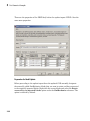
Unsupported Constraints
If a CAD assembly contains one or more unsupported constraints or mates, the
SimMechanics Link utility issues a warning message and creates a log file in the folder of
the XML import file. The warning message identifies the name of the log file; the log file
identifies the unsupported CAD constraints. In the event a constraint warning occurs,
review the log file and consider replacing the unsupported constraints or mates with
supported equivalents.
The constraint warning does not stop the creation of the XML import file. You can
import the XML file into a new SimMechanics model, but the model does not accurately
represent the original CAD assembly. During import, constraint warnings appear at the
MATLAB command line.
For a list of supported constraints, see “Constraints and Joints”.
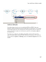
Correct Constraint Issue
When you import a CAD assembly that contains an unsupported constraint,
SimMechanics replaces the constraint with a Weld Joint block. The block provides zero
degrees of freedom between the connecting rigid body frames. To restore the original
degrees of freedom between the rigid bodies frames, you must:
• In the CAD platform, replace each unsupported constraint with a supported
equivalent. When you are finished, export the CAD assembly once again.
• In the imported SimMechanics model, manually replace each Weld Joint replacement
block with the appropriate joint block.
Note: Replacing unsupported constraints with supported equivalents works in a limited
number of cases. In certain cases, no adequate equivalent constraint or joint block exists.
2-25
2
CAD Export
Use SimMechanics Link Help
In the CAD platform, the SimMechanics Link utility provides a Help option. Select the
Help option to open the online SimMechanics Link help in MATLAB.
2-26
3
First-Generation Examples
Using realistic examples, these case studies illustrate how to translate mechanical
systems that are defined externally, as computer-aided design (CAD) assemblies, into
SimMechanics models.
• “Case Study Overview” on page 3-2
• “Export a CAD Rigid Body” on page 3-4
• “Translate CAD Constraints into SimMechanics Joints” on page 3-7
• “Export and Re-Export a Pendulum Assembly” on page 3-19
• “Export CAD Robot Arm” on page 3-37
• “Export a CAD Stewart Platform” on page 3-40
3
First-Generation Examples
Case Study Overview
The case studies show how to export a computer-aided design (CAD) assembly into a
SimMechanics model using the SimMechanics Link utility. Case studies include:
• “Export a CAD Rigid Body” — Translate CAD assembly with a single part into a
SimMechanics model with a single rigid body.
• “Translate CAD Constraints into SimMechanics Joints” — Translate CAD assemblies
with two constrained parts into SimMechanics models with two rigid bodies connected
by a joint.
• “Export and Re-Export a Pendulum Assembly” — Modify a CAD assembly and update
the imported SimMechanics model.
Note: This study requires Pro/ENGINEER.
• “Export CAD Robot Arm” — Translate an intermediate CAD assembly containing a
simple subassembly hierarchy.
• “Export a CAD Stewart Platform” — Translate a advanced CAD assembly with a
complex subassembly hierarchy.
Note: This study is not supported for Autodesk® Inventor®.
Requirements
The following assembly and exporting examples require a CAD platform supported by
the SimMechanics Link utility. To complete all the steps, you also need SimMechanics
Link and SimMechanics software.
The example CAD files are under $matlabroot/toolbox/physmod/smlink/
smlinkdemos/, in the subfolder appropriate to your supported CAD platform. The file
extensions of these files are specific to each CAD platform.
The assembly, geometric, kinematic, and part details differ from platform to platform. In
SolidWorks, constraints on CAD parts are called mates.
For More About Simulink and SimMechanics Blocks and Functions
For more information about SimMechanics software, consult the block and command
reference of the SimMechanics documentation.
3-2
Case Study Overview
For more information about Simulink software, consult the block and function reference
of the Simulink documentation.
3-3
3
First-Generation Examples
Export a CAD Rigid Body
In this section...
“Access the Example Files” on page 3-4
“Examine Rigid Body Parameters” on page 3-4
“Export CAD Rigid Body” on page 3-6
“Import CAD Rigid Body” on page 3-6
Access the Example Files
In this example, you export an assembly with one part and no constraints. Look for the
following two example CAD files in the SimMechanics Link examples folder:
• The full assembly file, cup_assembly.ASSEMBLYFILETYPE
• The part, a cup, in a file called cup.PARTFILETYPE
Although it has only one part, you must export the full assembly into XML, not just the
cup part.
Examine Rigid Body Parameters
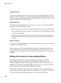
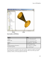
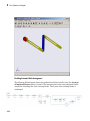
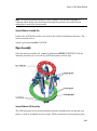
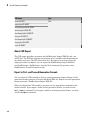
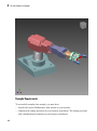
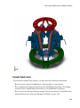
Open the cup assembly file in your CAD platform and check its geometry and mass
properties.
3-4
Export a CAD Rigid Body
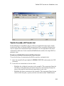
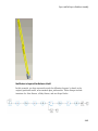
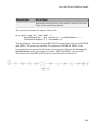
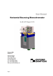
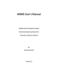
Cup Assembly in a CAD Platform
Property
Value
Volume
0.0001 cubic meters (m3)
Surface area
0.0381 square meters (m2)
Density
3.0 grams/cm3 = 3000 kg/m3
Mass
0.2906 kilograms (kg)
Principal moments of inertia at
the center of gravity
Ix = 0.00015, Iy = 0.00067,
Iz = 0.00067 kg-m2
The inertia tensor is computed at the center of gravity, with the coordinate axes aligned
with assembly base-origin axes, indicated in the figure. The x-axis is the cup's axis of
symmetry, and the y- and z-axes point across the cup.
3-5
3
First-Generation Examples
Export CAD Rigid Body
Using the SimMechanics Link interface to your CAD platform, export the assembly into
Physical Modeling XML format. The XML file cup_assembly.xml appears in your
working CAD folder.
Import CAD Rigid Body
Once you have generated the Physical Modeling XML file, you are ready to import the
cup assembly into a SimMechanics model. For a step-by-step description of the CAD
Import procedure, see “Import a CAD Rigid Body”.
3-6
Translate CAD Constraints into SimMechanics Joints
Translate CAD Constraints into SimMechanics Joints
In this section...
“Access the Example Files” on page 3-8
“Translation of Two-Part Models” on page 3-8
“Block Structure of Two-Part Models” on page 3-9
“Translate Assembly with Six-DoF Joint” on page 3-10
“Translate Assembly with Prismatic Joint” on page 3-11
“Translate Assembly with Revolute Joint” on page 3-14
“Translate Assembly with Rectangular Joint” on page 3-15
“Translate Assembly with Spherical-Spherical Massless Connector” on page 3-16
In “Export a CAD Rigid Body”, you create and export an assembly composed of a single
part. Because there are no other parts in that CAD assembly, the SimMechanics body is
welded to ground and has no degrees of freedom (DoFs). This lack of DoFs is not realistic
for most assemblies.
This study presents a set of complete CAD assemblies with both parts and constraints
and possessing DoFs. Each example assembly consists of two instances of the same part
file, representing two identical cubes. The study shows how to find the required files,
presents the essential steps for generating models from them, and describes the structure
common to all the generated models. It ends with specific assembly cases that include
two cubes:
• With no constraints, so that the cubes have the full six degrees of freedom relative to
one another
• Constrained in two different ways so as to produce the same result, a single prismatic
(translational) DoF between them
• Constrained so as to allow only a single revolute (rotational) DoF between them
• Constrained so as to allow two prismatic (translational) DoFs between them
• Constrained so as to allow relative spherical joint motion, with the two cubes
separated by a constant nonzero distance
In different assemblies, the two cubes are constrained with different constraint
combinations to create different relative DoFs between the cubes. In most cases, you can
represent one set of DoFs with a large number of different combinations of constraints.
3-7
3
First-Generation Examples
Access the Example Files
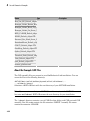
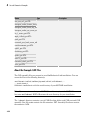
Look for the CAD assembly files of this study in the smlink/smlinkdemos directory. The
assemblies have the generic name, <assembly-name>.ASSEMBLYFILETYPE. The cube
part is in magic_cube.PARTFILETYPE.
Assembly Name
Assembly Configuration
sixDOF
Two cubes with no constraints
prismatic1
Two cubes with planar and cylindrical constraints
prismatic2
Two cubes with planar constraints
revolute
Two cubes with planar and cylindrical constraints
inplane
Two cubes with planar constraints
spherical_spherical_
massless_connector
Two cubes with a distance constraint
Translation of Two-Part Models
The procedure for exporting a two-part assembly and generating SimMechanics models
based on it is essentially the same for all the examples of this study.
Export Assembly
To see a two-part assembly and export it into a Physical Modeling XML file:
1
Open the assembly, <assembly-name>.ASSEMBLYFILETYPE. The two parts are
magic_cube-1 and magic_cube-2.
Locate any constraints imposed on the parts. These constraints define the relative
DoFs between the parts.
2
Using the SimMechanics Link interface to your CAD platform, export the CAD
assembly into Physical Modeling XML. The XML file is saved in your current
working CAD folder.
Import Model
You can import the Physical Modeling XML file into SimMechanics. SimMechanics
interprets the file and generates a corresponding SimMechanics model. The new model is
based on XML file structure and parameters. The CAD Import procedure requires access
to SimMechanics.
3-8
Translate CAD Constraints into SimMechanics Joints
1
Move or copy the XML file to a working MATLAB folder. In this folder, open
MATLAB.
2
At the command line, enter mech_import('<assembly_name>') to automatically
generate a model, <assembly_name>.mdl, based on <assembly_name>.xml.
3
Open the subsystem. The blocks are arranged in the common structure described in
“Block Structure of Two-Part Models”. A set of Joints represents the DoFs between
the two cubes.
Block Structure of Two-Part Models
In this study, all the models that you generate each have eight blocks. From the example
CAD assemblies, the models have a common structure because each assembly has a
fundamental root and two moving parts:
• The assembly fundamental root. As in any generated CAD-based model, the fourblock combination Machine Environment – Root Ground – Root Weld – Root Part
represents the assembly fundamental root. The Root Part is a nonmoving, zero-mass/
zero-inertia body.
• The moving bodies. The bodies representing the assembly parts are magic_cube-1
and magic_cube-2.
• The joints. In all the models, the first cube is connected by a Weld to Root Part and
cannot move. The second cube is connected to RootPart by a Joint that represents the
appropriate degrees of freedom (DoFs).
Depending on the DoFs in a particular assembly, CAD translation configures the
Joint to represent different DoFs with combinations of prismatic, revolute, and
spherical primitives. The second cube can move with respect to the first cube through
the DoFs represented by the Joint.
Some of the blocks in the generated models are redundant. You can manually edit and
simplify the models without changing their physical properties.
CAD Constraints Restrict Degrees of Freedom
CAD platforms treat unconstrained parts as free rigid bodies with six mechanical degrees
of freedom. To reduce the degrees of freedom of a CAD part, and therefore the ways that
part can move, you must constrain that part. Applying a CAD constraint between two
parts reduces the ways the two parts can move with respect to each other. In a two-part
CAD assembly, one part is static relative to ground.
3-9
3
First-Generation Examples
Translate Assembly with Six-DoF Joint
The simplest assembly with two parts has no constraints between the parts. The parts
can move with respect to one another with all six degrees of freedom (DoFs).
Export Assembly
To see and export the assembly:
1
Open the assembly, sixDOF.ASSEMBLYFILETYPE.
The cube parts have no constraints. Therefore, relative to one another, the cubes are
unconstrained in their motion and have six relative DoFs.
2
Export this CAD assembly into the file, sixDOF.xml.
Import Model
To generate a model based on the assembly:
1
At the MATLAB command line, enter mech_import('sixDOF') to generate a
model, sixDOF.mdl.
2
Inspect the model. There are eight blocks.
The Six-DoF Joint represents the six DoFs between the two cubes with one spherical
and three prismatic primitives.
3-10
Translate CAD Constraints into SimMechanics Joints
Translate Assembly with Prismatic Joint
In the following two assemblies, the two cubes are constrained to have only a single
translational degree of freedom (DoF) between them. These assemblies illustrate two
ways to express one translational degree of freedom. You can experiment with other
constraints to find more. In the translated SimMechanics models, this single DoF is a
prismatic joint.
Prismatic as a Cylindrical Constraint and a Planar Constraint
To see the first way of constraining the DoFs to produce a prismatic joint:
1
Open the assembly file, prismatic1.ASSEMBLYFILETYPE, and examine its CAD
hierarchy.
2
Locate the two constraints on the two cubes.
• Highlight the cylindrical constraint in the assembly. This constraint allows the
two cubes to only slide along and rotate about the z-axis running through the
center of the parallel and concentric upper holes of each cube.
• Highlight the planar constraint in the assembly. This constraint allows the two
cubes to slide along the y-z plane, with the two sides marked “SimMechanics”
3-11
3
First-Generation Examples
sharing a common plane, representing two translational DoFs. The constraint
also allows the two cubes to rotate about the x-axis. The cubes are not allowed to
rotate about any other axis, or to translate perpendicular to the y-z plane.
With these two constraints, the two cubes can only slide along the z-axis common to
the two upper concentric holes. The second constraint prevents rotation about this axis,
leaving the whole assembly with only one translational DoF.
Cylindrical and Planar Constraints on Two Cubes (SolidWorks)
Prismatic as Two Orthogonal Planar Constraints
To see the second way of constraining the DoFs to produce a prismatic joint:
3-12
1
Open the assembly file, prismatic2.ASSEMBLYFILETYPE, and examine its CAD
hierarchy.
2
Locate the two constraints on the two cubes.
Translate CAD Constraints into SimMechanics Joints
• Highlight the first planar constraint in the assembly. This constraint allows the
two cubes to slide along the y-z plane, with the two sides marked “SimMechanics”
sharing a common plane, representing two translational DoFs. It also allows the
two cubes to rotate about the x-axis. The cubes are not allowed to rotate about
any other axis, or to translate perpendicular to the y-z plane.
• Highlight the second planar constraint in the assembly. This constraint allows
the two cubes to slide along the x-z plane, with the two sides marked “The
MathWorks” sharing a common plane, representing two translational DoFs. The
constraint also allows the two cubes to rotate about the y-axis. The cubes are not
allowed to rotate about any other axis, or to translate perpendicular to the x-z
plane.
With these two constraints, the two cubes can only slide along the z-axis common to the
two planes y-z and x-z, leaving the whole assembly with only one translational DoF.
Two Planar Constraints on Two Cubes (SolidWorks)
3-13
3
First-Generation Examples
Export Assemblies and Import Models
To create models from the assemblies:
1
Export the two assemblies into the XML files, prismatic1.xml and
prismatic2.xml.
2
Copy or move them to a MATLAB working folder. At the MATLAB command line,
generate SimMechanics models using mech_import.
In both models, the assemblies are translated into block diagrams of eight blocks each.
The Prismatic Joint represents the single translational DoF between the two cubes with
one prismatic primitive along the z-axis.
Translate Assembly with Revolute Joint
In the following assembly, the two cubes are constrained to have only a single rotational
degree of freedom (DoF) between them. In the translated SimMechanics model, this
single DoF is a revolute joint.
Open CAD Assembly
To see an assembly with one rotational DoF:
1
Open the assembly file, revolute.ASSEMBLYFILETYPE, and examine its CAD
hierarchy.
2
Locate the two constraints on the two cubes.
• Highlight the cylindrical constraint in the assembly. This constraint allows the
two cubes to slide along and rotate about the z-axis running through the center of
the parallel and concentric upper holes of each cube.
• Highlight the planar constraint in the assembly. This constraint allows the two
cubes to slide along the x-y plane, with the parallel sides sharing a common
plane. The constraint also allows the two cubes to rotate about the z-axis. The
cubes are not allowed to rotate about any other axis, or to translate perpendicular
to the x-y plane.
With these two constraints, the two cubes can only rotate about the z-axis orthogonal to
the x-y plane, leaving the whole assembly with only one rotational DoF.
Export Assembly and Import Model
To generate a model based on the assembly:
3-14
Translate CAD Constraints into SimMechanics Joints
1
Export the assembly as the file, revolute.xml. Copy or move it to a MATLAB
working folder.
2
At the MATLAB command line, generate a SimMechanics model using
mech_import.
The assembly is translated into a block diagram of eight blocks. The Revolute Joint
represents the single rotational DoF between the two cubes with one revolute primitive
about the z-axis.
Translate Assembly with Rectangular Joint
In the following assembly, the two cubes are constrained to have only two translational
degrees of freedom (DoFs) between them. In the translated SimMechanics model, these
two DoFs are two prismatic joints.
Open CAD Assembly
To see an assembly with two translational DoFs:
1
Open the assembly file, inplane.ASSEMBLYFILETYPE, and examine its CAD
hierarchy.
2
Locate the two constraints on the two cubes.
• Highlight the first planar constraint in the assembly. This constraint allows the
two cubes to slide along the y-z plane, with the two sides marked “SimMechanics”
sharing a common plane. The constraint also allows the two cubes to rotate
about the x-axis. The cubes are not allowed to rotate about any other axis, or to
translate perpendicular to the y-z plane.
• Highlight the second planar constraint in the assembly. This constraint allows
the two cubes to slide parallel to the x-z plane, with the two sides marked “The
MathWorks'' parallel but not necessarily in the same plane. It also allows the two
cubes to translate perpendicular to the x-z plane and to rotate about the y-axis.
The cubes are not allowed to rotate about any other axis.
With these two constraint, the two cubes can only slide in the y-z plane, leaving the
whole assembly with only two translational DoFs.
Export Assembly and Import Model
To generate a model based on the assembly:
3-15
3
First-Generation Examples
1
Export the assembly as the file, inplane.xml. Copy or move it to a MATLAB
working folder.
2
At the MATLAB command line, generate a SimMechanics model using
mech_import.
The assembly is translated into a block diagram of eight blocks. The In-Plane Joint
represents the two translational DoFs between the two cubes with two prismatic
primitives, along the y-axis and the z-axis.
Translate Assembly with Spherical-Spherical Massless Connector
In the following assembly, the two cubes are constrained to have six rotational degrees
of freedom (DoFs) between them, represented by two spherical primitives. The spherical
primitives pivot independently about two pivot points at a fixed relative distance. In the
translated SimMechanics model, a spherical-spherical massless connector represents
these six DoFs.
Open CAD Assembly
To see an assembly with three rotational DoFs separated from three other rotational
DoFs:
1
Open the assembly file,
spherical_spherical_massless_connector.ASSEMBLYFILETYPE
and examine its CAD hierarchy.
2
Locate the one constraint on the two cubes.
Highlight this distance-offset constraint. The two spherical pivot points occur one
on each cube and mark the endpoints of the rigid massless connector. The cubes
can move so that the distance between these two endpoints (the length of the
massless connector) does not change. The constraint allows the two cubes to pivot
independently about their connector endpoints.
3-16
Translate CAD Constraints into SimMechanics Joints
Distance Constraint on Two Cubes (SolidWorks)
Export Assembly and Import Model
To generate a model based on the assembly:
1
Export the assembly as a file,
spherical_spherical_massless_connector.xml
2
Copy or move it to a MATLAB working folder.
3
At the MATLAB command line, generate a SimMechanics model using
mech_import.
The assembly is translated into a block diagram of eight blocks, arranged in the common
structure described in “Block Structure of Two-Part Models”.
3-17
3
First-Generation Examples
The Spherical-Spherical massless connector Joint block represents the two spherical
primitives, each with three rotational DoFs, independently pivoting at each end of the
massless, rigid connector connecting the two cubes.
3-18
Export and Re-Export a Pendulum Assembly
Export and Re-Export a Pendulum Assembly
In this section...
“About Model Update” on page 3-19
“CAD Assembly Files” on page 3-19
“Translate CAD Assembly” on page 3-20
“Modify Pendulum Assembly and Update SimMechanics Model” on page 3-24
“Add New Body to Create a Triple Pendulum” on page 3-30
“Update Imported Model While Retaining Manual Joint Replacements” on page 3-35
“Selectively Update Imported Model” on page 3-36
About Model Update
Note: The CAD assembly files of this case study require Pro/ENGINEER.
The following example shows how to update a previously generated SimMechanics
model with a new XML file exported after changes have been made to the original CAD
assembly. The example starts with a double pendulum assembly.
For a general discussion of retranslation and update-import, see “Retranslate CAD
Assembly”.
CAD Assembly Files
Look for the following seven CAD files of this case study in the SimMechanics Link
examples folder.
File Name
CAD File Type
dpen.ASSEMBLYFILETYPE
Assembly
tpen.ASSEMBLYFILETYPE
Assembly
hook.ASSEMBLYFILETYPE
Subassembly
3-19
3
First-Generation Examples
File Name
CAD File Type
mid_part.PARTFILETYPE
pend.PARTFILETYPE
Parts (main assembly)
hook.PARTFILETYPE
hookbase.PARTFILETYPE
Parts (subassembly)
Translate CAD Assembly
Open the dpen assembly file and export it into an XML file.
Export the assembly through the SimMechanics Link menu of the CAD platform's
menu bar. The result is an XML file called dpen.xml.
3-20
Export and Re-Export a Pendulum Assembly
Import CAD Assembly and Generate SimMechanics Model
To import the XML file and generate the SimMechanics model, you can either use the
import dialog box or work with the full command at the MATLAB command line.
Open the dialog box by entering mech_import at the command line.
3-21
3
First-Generation Examples
The alternative is to use the full command with specified import options:
mech_import('dpen.xml','ImportMode',0,...
'ModelToImportInto','dpen_original');
This model results from the import step. The blocks are created at the top level.
With visualization enabled, you see this SimMechanics model with custom bodies defined
by STL files exported when the XML file was exported.
3-22
Export and Re-Export a Pendulum Assembly
Import Physical Modeling XML File
If you want to import the assembly into a model subsystem, rather than at the top level
of a model, use the SubsystemToImportInto option of the mech_import command.
(You can also use the parallel options in the import dialog box.) For example, you can
import the assembly into a subsystem named Plant.
mech_import('dpen.xml','ImportMode',0,...
'ModelToImportInto','dpen_original',...
'SubsystemToImportInto','Plant');
3-23
3
First-Generation Examples
Modify Pendulum Assembly and Update SimMechanics Model
You can change part properties in the original assembly and reimport the assembly,
with those changes, to update the model. You can also make direct changes by hand to
the original generated model and preserve those changes even as you update it with
assembly changes.
In this example, you now cut out material from the links to make them lighter. You also
connect joint and body sensors in the SimMechanics model to implement a controller.
Now you want to update the SimMechanics model with changes from the assembly
without undoing the additions you made by hand.
Export Modified CAD Assembly
Change the double pendulum assembly and generate a new XML file from it.
1
Open the pend part file and unsuppress the Extrude2 feature to enable the hole in
the parts. Do this by right-clicking Extrude2 in the tree view and selecting Resume.
Save the part file.
2
3-24
Open and re-export the dpen assembly file to obtain the new XML file, which is
assumed to be named dpen_with_holes.xml.
Export and Re-Export a Pendulum Assembly
Modification to Imported SimMechanics Model
In this example, you have separately made the following changes, by hand, to the
original generated model, now renamed dpen_withsensors. These changes include
insertion of a Joint Sensor, a Body Sensor, and two Scope blocks.
3-25
3
First-Generation Examples
These are the properties of the PEND body before the update-import. PEND-1 has the
same mass properties.
Preparation for Model Update
Before proceeding to the update-import from the updated CAD assembly, designate
the manually added SimMechanics blocks that you want to retain and keep connected
to the originally imported blocks. Right-click the sensor blocks and select the Retain
connectivity to imported blocks option under the SimMechanics submenu. This
option is selected by default.
3-26
Export and Re-Export a Pendulum Assembly
SimMechanics Model Update
Now update-import in such a way as to modify the PEND and PEND-1 body mass
properties, without changing the manually added blocks and connections. You can either
use the import dialog box or the command line with fully specified options to update the
existing model. This example uses the dialog box, opened by entering mech_import at
the command line.
The dialog box is configured so that dpen_with_holes.xml is the file imported to
update the modified dpen_withsensors model. Because the dialog box is set to update an
existing model, the Update and Backup options in the Advanced Options tab are now
enabled.
3-27
3
First-Generation Examples
Alternatively, if you want to use the command with fully specified options, enter:
mech_import('dpen_with_holes','ImportMode',1,...
'ModelToImportInto','dpen_withsensors','LayoutWithUpdate',1,...
'EnableIndvlBlkUpdCtrl',1,'BackupMode',0)
The updated model looks like the following. The sensors and Scopes are retained.
However, the PEND body properties are now different, because of the new holes in the
parts. The PEND-1 mass properties are changed in the same way.
3-28
Export and Re-Export a Pendulum Assembly
The updated bodies, displayed in SimMechanics visualization, appear differently as well,
as determined by the new STL files exported from the updated assembly at the same
time the new XML file was created.
3-29
3
First-Generation Examples
Add New Body to Create a Triple Pendulum
The changes to an assembly that you can re-export are not limited to changes in existing
parts (bodies). You can add or remove parts, re-export, then update-import an older
version of the generated model with the changes.
In this example, in addition to the holes in the parts you previously made, you change the
original assembly further by adding a new part (link) between the two original pendulum
links, making the assembly a triple pendulum. This addition changes the topology of the
assembly (the assembly's connectivity), beyond the property changes to the individual
links.
3-30
Export and Re-Export a Pendulum Assembly
Modify and Update CAD Assembly
To see such a changed assembly, open the tpen assembly file. The tpen assembly is a
copy of the dpen assembly with a link inserted. Export a new XML file, which is named
tpen.xml.
Updating the Existing Generated Model
Update the existing dpen_withsensors model with the changes to the assembly. These
are the required options in the import dialog box.
3-31
3
First-Generation Examples
The Advanced Options tab shows important options selected for this example.
Advanced Option
Effect of Option
Arrange all updated Selecting this option causes the importer to rearrange all the
imported and updated blocks.
blocks
If cleared, the importer does not alter the layout of the existing
blocks, whether updated or not, and places the newly imported
blocks around the bounding box for the already existing blocks.
In many cases, this means you have to rearrange the newly
imported blocks by hand.
3-32
Respect individual
block update
settings
Selecting this option preserves the associativity information
specified on each block.
Backup mode
Using this pull-down menu allows you to choose how the model
is backed up during update. the backup options.
Export and Re-Export a Pendulum Assembly
Advanced Option
Effect of Option
By default, the backup copy of the model is created in the same
folder as the model being updated.
The equivalent command line import command is:
mech_import('tpen.xml','ImportMode',1,...
'ModelToImportInto','dpen_withsensors','LayoutWithUpdate',1,...
'EnableIndvlBlkUpdCtrl',1,'BackupMode',0)
The block diagram shows that the part MID_PART inserted between the two links PEND
and PEND-1. The sensors are retained. The properties of PEND and PEND-1 have
been updated (to incorporate the holes that are now present). Because the Arrange all
updated blocks option was selected, the blocks PEND and PEND-1 were moved to
accommodate the block MID_PART and the joints Revolute2 and Revolute3.
3-33
3
First-Generation Examples
Disabling Automatic Block Arrangement
The following block diagram shows the updated model that results when the Arrange
all updated blocks option is cleared. The importer places the newly imported blocks
around the bounding box of the existing blocks. The layout of the existing blocks is
unchanged.
3-34
Export and Re-Export a Pendulum Assembly
Update Imported Model While Retaining Manual Joint Replacements
In circumstances where a set of assembly constraints imposes ambiguous restrictions on
the motions of two parts, the SimMechanics Link exporter cannot resolve the constraint
set into a moving joint. In such cases, it exports a Weld joint. If so, it is up to you to
manually replace the Weld joint with the appropriate moving joint in the generated
model. Even in situations where the exporter creates a moving joint, it might not reflect
the degrees of freedom that you want, and you might want replace it with another. When
you have replaced such joints in an imported model, and you want to update the model
with changes from the CAD assembly, you generally want to retain the replacements you
made manually.
1
Create a dpen_jointrep model in the following way.
Open the dpen_withsensors model and replace the Revolute joint between the two
link bodies by a Planar joint that has some compliance in the plane perpendicular to
the original revolute axis. Rename the Planar joint to Revolute with Compliance.
2
To update this model with changes to the link body properties, but to still retain
the new Planar joint, right-click the Revolute with Compliance block and select the
Retain connectivity to imported blocks option. It is selected by default.
3
Update this model with the new XML file that has changes to the properties of the
links.
3-35
3
First-Generation Examples
mech_import('dpen.xml','ImportMode',1,...
'ModelToImportInto','dpen_jointrep','LayoutWithUpdate',1,...
'EnableIndvlBlkUpdCtrl',1,'BackupMode',0)
The updated model retains the Revolute with Compliance joint.
Selectively Update Imported Model
You can update certain bodies while not updating other bodies with changes. Prevent a
particular body from being updated during reimport by:
1
Right-clicking the body and selecting the Retain without updating properties
option under the SimMechanics submenu.
2
Selecting the Respect individual block update settings option in the import
dialog box.
If you use the full command instead, you need to set the EnableIndvlBlkUpdCtrl
option to true.
Clearing the Respect individual block update settings check box causes the importer
to update all blocks, disregarding the update settings on the individual blocks.
3-36
Export CAD Robot Arm
Export CAD Robot Arm
In this section...
“CAD Robot Arm Files” on page 3-37
“CAD Robot Arm Properties” on page 3-37
“Export Robot Arm Assembly” on page 3-39
“Import Model” on page 3-39
CAD Robot Arm Files
The following example is based on a more complex CAD assembly, a robot arm. It
includes multiple parts, two closed loops, multiple constraints, and a subassembly. Look
for the 11 CAD files of this case study in the SimMechanics Link examples folder.
File Name
CAD File Type
robot.ASSEMBLYFILETYPE
Assembly
grip.ASSEMBLYFILETYPE
Subassembly (flexible)
base.PARTFILETYPE
forearm.PARTFILETYPE
upperarm.PARTFILETYPE
wrist.PARTFILETYPE
Parts (main assembly)
fingertips.PARTFILETYPE (twice)
firstfingerlink.PARTFILETYPE
firstfingerlinkL.PARTFILETYPE
metacarpal.PARTFILETYPE
secondfingerlink.PARTFILETYPE (twice)
Parts (subassembly)
CAD Robot Arm Properties
Open the assembly file for the whole robot.
3-37
3
First-Generation Examples
Robot Arm Assembly in a CAD Platform
In the assembly tree to the left of the window, examine the CAD hierarchy:
• Five of the part files are grouped into the subassembly grip. The subassembly uses
two instances each of fingertips and secondfingerlink.
• The subassembly has its own group of 18 constraints, MateGroup1.
Two constraints, Angle1 and Angle2, are not active. If they were, they would lock the
grip fingers into the open position. Here, each grip finger can move separately.
• The other four part files are separate and grouped into the main assembly.
• The main assembly has its own MateGroup1, consisting of seven constraints.
The whole assembly has eight DoFs. The grip subassembly alone contains two, allowing
each finger to open and close separately. The main assembly has six DoFs:
• The upper arm can move relative to the base by pitching, yawing, and rolling (three
DoFs).
• The forearm can yaw relative to the upper arm (one DoF).
3-38
Export CAD Robot Arm
• The wrist can pitch relative to the forearm (one DoF).
• The grip can rotate about its symmetry axis (one DoF).
Export Robot Arm Assembly
Apply any changes you want to the assembly configuration or settings. If you change the
assembly or any subassemblies, you need to rebuild the assembly before exporting it to
XML.
Using the SimMechanics Link interface to your CAD platform, export the assembly into
Physical Modeling XML. The XML file robot.xml appears in your working CAD folder.
Import Model
Once you have exported the CAD assembly, you can generate the corresponding
SimMechanics model. Using the mech_import command, you import the Physical
Modeling XML file that SimMechanics Link generated during export, and let
SimMechanics automatically generate the model for you. Then, review the model and
make any required changes to the model. For a step-by-step description of the CAD
Import procedure, see “Import Robot Arm Model”.
3-39
3
First-Generation Examples
Export a CAD Stewart Platform
In this section...
“About the Stewart Platform” on page 3-40
“CAD Assembly” on page 3-40
“Open Assembly” on page 3-41
“Export Assembly” on page 3-42
“Import Model” on page 3-42
About the Stewart Platform
The Stewart platform consists of two plates connected by six mobile and extensible
legs. The lower or base plate is immobile. The upper or mobile plate has six degrees of
freedom, three rotational and three translational. The platform is a six-degree-of-freedom
(DoF) mechanical system used for accurate positioning applications. It is highly stable
and easy to control.
The platform's six legs each have two parts, an upper and a lower leg, with a piston-like
cylindrical DoF between each pair of parts. The legs are connected to the base plate and
the top plate by universal joints at each end of each leg. (These universals are not just
sets of abstract DoFs. Each also contains a spider-like body, while also having two DoFs.)
The upper part of each leg can slide into and out of the lower leg, allowing each leg to be
varied in length. The position and orientation of the mobile platform (top plate) varies
depending on the lengths to which the six legs are separately adjusted.
Once the top is connected to the legs, the entire Stewart platform assembly has 36
DoFs. Only six DoFs are independent, the same as the top plate would have if it were
disconnected. You can think of these independent DoFs as the six adjustable leg lengths
or as equivalent to the six DoFs of the mobile plate.
CAD Assembly
The following example uses a complex computer-aided design (CAD) assembly that
models the Stewart platform.
3-40
Export a CAD Stewart Platform
Note The Stewart platform assembly in this example is an advanced example of
computer-aided design. You should work through the previous case studies before
attempting to work with this assembly.
Stewart Platform Assembly Files
Look for the 45 CAD files of this case study in the smlink/smlinkdemos directory. The
master assembly file is:
stewart_platform.ASSEMBLYFILETYPE
Open Assembly
Open the master assembly file, stewart_platform.ASSEMBLYFILETYPE. Click the
assembly and rotate it to view the top and bottom plates and the legs.
Stewart Platform CAD Assembly
The CAD hierarchy for the Stewart platform contains assemblies for the top and base
plates, as well as assemblies for the six legs. All the constraints on the assembly parts
3-41
3
First-Generation Examples
are grouped into one group, containing 30 constraints. There are 448 component parts
and 38 subassemblies, which you can open individually to examine the separate parts.
The base plate is about 24 centimeters (cm) in diameter; the top plate about 16.5 cm.
When centered and oriented flat, the top plate is about 20 cm above the base. The
assembly models the platform material as aluminum (about 2.7 grams per cubic cm).
Export Assembly
Apply any changes you want to the assembly configuration or settings. If you change the
assembly or any subassemblies, you need to rebuild the assembly before exporting it to
XML.
Using the SimMechanics Link interface to your CAD platform, export the assembly into
Physical Modeling XML. Because the assembly is so complex, the export process takes
longer than it does for simpler assemblies. As the export proceeds, various parts and
subassemblies are highlighted. When the highlighting stops, the export is finished.
The exported model appears as stewart_platform.xml in your working CAD folder.
Import Model
Once you have exported the CAD assembly, you can generate the corresponding
SimMechanics model. Using the mech_import command, you import the Physical
Modeling XML file that SimMechanics Link generated during export, and let
SimMechanics automatically generate the model for you. Then, review the model and
make any required changes to the model. For a step-by-step description of the CAD
Import procedure, see “Import a CAD Stewart Platform Model”.
3-42
4
Second-Generation Examples
• “Export Robot Assembly from SolidWorks Software” on page 4-2
• “Export Robot Assembly from Autodesk Inventor Software” on page 4-7
• “Export Robot Assembly from Creo Software” on page 4-12
• “Export Stewart Platform from SolidWorks Software” on page 4-18
• “Export Stewart Platform from Creo Software” on page 4-24
4
Second-Generation Examples
Export Robot Assembly from SolidWorks Software
In this section...
“Example Requirements” on page 4-3
“Open Robot Assembly” on page 4-4
“Export CAD Assembly” on page 4-4
“Verify CAD Export Files” on page 4-5
“About the Example CAD Files” on page 4-5
“About CAD Export” on page 4-6
“Export in First- and Second-Generation Formats” on page 4-6
In this example, you export a SolidWorks CAD assembly that represents a robot arm.
The export procedure generates one XML file and a set of STL files that you can import
into SimMechanics to generate a new second-generation model.
The example begins with a procedure to export the CAD assembly. Information on
the robot CAD files and CAD Export follows the export procedure. To import the robot
assembly into a SimMechanics Second Generation model, see “Import Robot Arm Model”.
The following figure shows the robot CAD assembly you export in this example.
4-2
Export Robot Assembly from SolidWorks Software
Example Requirements
To successfully complete this example, you must meet the following requirements:
• Have the latest version of SimMechanics Link installed on your machine.
• Have completed the linking procedure for your SolidWorks installation. The linking
procedure adds a SimMechanics Link add-in to the SolidWorks installation.
• Have access to the robot example files that accompany the SimMechanics Link
installation. See “Export Robot Assembly from SolidWorks Software” on page
4-2.
4-3
4
Second-Generation Examples
Open Robot Assembly
Before you can export the robot assembly, you must load the assembly into SolidWorks.
1
Open SolidWorks on your machine.
2
Select File > Open
3
Navigate to the file directory that contains the robot CAD files.
Note: The directory that contains the robot CAD files for the SolidWorks platform is
<MATLAB Root>\toolbox\physmod\smlink\smlinkdemos\...
...solidworks\robot
4
Select file robot.SLDASM.
5
Click Open.
The CAD platform opens the robot assembly.
Export CAD Assembly
Once you successfully open the robot CAD assembly in your SolidWorks installation, you
can export the assembly in second-generation format:
4-4
1
On the SolidWorks tool bar, select SimMechanics Link > Export and click
SimMechanics Second Generation....
2
In the File name: field of the Save As dialog box, enter sm_robot and select a
directory to export the files.
3
Click Save.
Export Robot Assembly from SolidWorks Software
Note: Large CAD assemblies require more time to complete the export process. Allow
up to a few minutes for the export process to complete.
Verify CAD Export Files
Confirm the following files exist in the specified export directory:
• XML file — provides structure of model and parameters of parts.
• STL files — provides surface geometry of parts.
About the Example CAD Files
The CAD assembly files are present in your SimMechanics Link installation. You can
access the files in the following directory:
<MATLAB Root>\matlab\toolbox\physmod\smlink\smlinkdemos\...
...solidworks\robot
Substitute <MATLAB Root> with the root directory of your MATLAB installation.
Note: If you are not sure what your MATLAB root directory is, at the MATLAB command
line enter matlabroot. MATLAB returns the root directory for your installation.
The \robot directory contains a set of CAD files that define each CAD part and CAD
assembly. Part file names contain the file extension .SLDPRT. Assembly file names
contain the extension .SLDASM. A drawing file with extension .SLDDRW contains robot
arm dimensions.
The robot assembly contains nine parts and two assemblies: robot.SLDASM and
grip.SLDASM. File robot.SLDASM models the robot root assembly. File grip.SLDASM
models the robot grip subassembly.
The following table lists all files the example requires.
File Name
Type
robot.SLDASM
Assembly
grip.SLDASM
4-5
4
Second-Generation Examples
File Name
Type
wrist.SLDPR
Part
upperarm.SLDPRT
secondfingerlink.SLDPRT
metacarples.SLDPRT
firstfingerlinkL.SLDPRT
forearm.SLDPRT
firstfingerlink.SLDPRT
fingertips.SLDPRT
base.SLDPRT
About CAD Export
The CAD export procedure generates one SimMechanics Import XML file and a set
of STL files. The XML file contains the structure of the assembly and the parameters
that define each part. The STL files define the 3-D geometry of each part. Once the
export procedure is complete, you can import the SimMechanics Import XML file
into SimMechanics. SimMechanics uses the file to automatically generate a new
SimMechanics Second Generation model.
Export in First- and Second-Generation Formats
You can export a CAD assembly in first- or second-generation formats. Export in firstgeneration format generates a Physical Modeling XML file. Export in second-generation
format generates a SimMechanics Import XML file.
When you import the CAD assembly, you must use the appropriate command for the
format selected. If you export a model in first-generation format, you must use the
mech_import command. If you export a model in second-generation format, you must
use the smimport command.
4-6
Export Robot Assembly from Autodesk Inventor Software
Export Robot Assembly from Autodesk Inventor Software
In this section...
“Example Requirements” on page 4-8
“Open Robot Assembly” on page 4-9
“Export CAD Assembly” on page 4-9
“Check CAD Export Files” on page 4-10
“About the Example CAD Files” on page 4-10
“About CAD Export” on page 4-11
In this example, you export an Autodesk Inventor CAD assembly that represents a robot
arm. The export procedure generates one XML file and a set of STL files that you can
import into SimMechanics to generate a new second-generation model.
The example begins with a procedure to export the CAD assembly. Information on
the robot CAD files and CAD Export follows the export procedure. To import the robot
assembly into a SimMechanics Second Generation model, see “Import Robot Arm Model”.
The following figure shows the robot CAD assembly you export in this example.
4-7
4
Second-Generation Examples
Example Requirements
To successfully complete this example, you must have:
• Installed the latest SimMechanics Link version on your machine.
• Completed the linking procedure for your Inventor installation. The linking procedure
adds a SimMechanics Link add-in to the Inventor installation.
4-8
Export Robot Assembly from Autodesk Inventor Software
Open Robot Assembly
Before you can export the robot assembly, you must load the assembly into Inventor.
1
Open Inventor on your machine.
2
Select File > Open
3
Navigate to the file directory that contains the robot CAD files.
Note: The directory that contains the robot CAD files for the Autodesk Inventor
platform is
<MATLAB Root>\toolbox\physmod\smlink\smlinkdemos\...
...inventor\robot
4
Select file robot.IAM.
5
Click Open.
The CAD platform opens the robot assembly.
Export CAD Assembly
Once you successfully open the robot CAD assembly in your Inventor installation, you
can export the assembly in second-generation format:
1
In the Inventor toolbar, select Add-Ins > Export SimMechanics Second
Generation.
2
In the File name: field of the Save As dialog box, enter sm_robot and select a
directory to export the files.
3
Click Save.
4-9
4
Second-Generation Examples
Note: Large CAD assemblies require more time to complete the export process. Allow
up to a few minutes for the export process to complete.
Check CAD Export Files
Confirm the following files exist in the export directory you specified:
• XML file—Provides structure of model and parameters of parts.
• STL files—Provide surface geometry of parts.
About the Example CAD Files
The CAD assembly files are present in your SimMechanics Link installation. You can
access the files in the following directory:
<MATLAB Root>\matlab\toolbox\physmod\smlink\smlinkdemos\...
...inventor\robot
Substitute <MATLAB Root> with the root directory of your MATLAB installation.
Note: If you are not sure what your MATLAB root directory is, at the MATLAB command
line enter matlabroot. MATLAB returns the root directory for your installation.
The \inventor\robot directory contains a set of CAD files that define each CAD part
and CAD assembly. Part file names contain the file extension .IPT. Assembly file names
contain the extension .IAM.
The robot assembly contains nine parts and two assemblies: robot.IAM and grip.IAM.
File robot.IAM models the robot root assembly. File grip.IAM models the robot grip
subassembly.
The following table lists all files the example requires.
File Name
Type
robot.IAM
Assembly
grip.IAM
4-10
Export Robot Assembly from Autodesk Inventor Software
File Name
Type
wrist.IPT
Part
upperarm.IPT
secondfingerlink.IPT
metacarples.IPT
firstfingerlinkL.IPT
forearm.IPT
firstfingerlink.IPT
fingertips.IPT
base.IPT
About CAD Export
The CAD export procedure generates one SimMechanics Import XML file and a set
of STL files. The XML file contains the structure of the assembly and the parameters
that define each part. The STL files define the 3-D geometry of each part. Once the
export procedure is complete, you can import the SimMechanics Import XML file
into SimMechanics. SimMechanics uses the file to automatically generate a new
SimMechanics Second Generation model.
4-11
4
Second-Generation Examples
Export Robot Assembly from Creo Software
In this section...
“Example Requirements” on page 4-13
“Open Robot Assembly” on page 4-13
“Export CAD Assembly” on page 4-14
“Verify CAD Export Files” on page 4-15
“About the Example CAD Files” on page 4-16
“About CAD Export” on page 4-17
“Export in First- and Second-Generation Formats” on page 4-17
In this example, you export a Creo (Pro/ENGINEER) CAD assembly that represents a
robot arm. The export procedure generates one XML file and a set of STL files that you
can import into SimMechanics to generate a new second-generation model.
The example begins with a procedure to export the CAD assembly. Information on
the robot CAD files and CAD Export follows the export procedure. To import the robot
assembly into a SimMechanics Second Generation model, see “Import Robot Arm Model”.
The following figure shows the robot CAD assembly that you export in this example.
4-12
Export Robot Assembly from Creo Software
Example Requirements
To successfully complete this example, you must meet the following requirements:
• Have the latest version of SimMechanics Link installed on your machine.
• Have completed the linking procedure for your Creo installation. The linking
procedure adds a SimMechanics Link add-on tool to the installation.
• Have access to the robot example files that accompany the SimMechanics Link
installation.
Open Robot Assembly
Before you can export the robot assembly, you must load the assembly into Creo.
1
Open Creo on your machine.
2
Select File > Open
4-13
4
Second-Generation Examples
3
Navigate to the file directory that contains the robot CAD files.
Note: The directory that contains the robot CAD files for the Pro/ENGINEER
platform is
<MATLAB Root>\toolbox\physmod\smlink\smlinkdemos\proe\robot
4
Select file robot.ASM.
5
Click Open.
The CAD platform opens the robot assembly.
Export CAD Assembly
Once you successfully open the robot CAD assembly in your Creo installation, you can
export the assembly in second-generation format:
1
In the Creo toolbar, click Tools.
2
Select SimMechanics Link > Export.
3
Select the SimMechanics generation you wish to export the assembly into.
Options include SimMechanics First Generation and SimMechanics Second
Generation.
4
In the File name: field of the Select Folder dialog box, enter select a directory to
export the files into.
Note: Do not enter a name in the File name field. The field should contain only a
dot .
4-14
5
Click Open.
6
In the new dialog box, enter file name sm_robot and click the green arrow.
Export Robot Assembly from Creo Software
Note: SimMechanics Link generates a new SimMechanics Import XML file and a set
of STL files that you can import into a second-generation model.
Verify CAD Export Files
Confirm the following files exist in the export directory you specified:
SimMechanics Import XML File
Name
Type
Description
sm_robot.xml
SimMechanics Import XML The XML file defines
File
the structure of the CAD
assembly. The file also
contains the parameters
required to model each part
in the CAD assembly.
STL Geometry Files
Note: In the Name column, <identifier> is a set of numeric and alphabetic characters
that identifies each file.
Name
Type
Description
base_prt.STL
STL geometry files
The STL files define the
surface geometry of each
robot CAD part
fingertips_prt.STL
firstfingerlink_prt.STL
firstfingerlinkl_prt.STL
forearm_prt.STL
metacarples_prt.STL
secondfingerlink_prt.STL
upperarm_prt.STL
wrist_prt.STL
4-15
4
Second-Generation Examples
About the Example CAD Files
The CAD assembly files are present in your SimMechanics Link installation. You can
access the files in the following directory:
<MATLAB Root>\matlab\toolbox\physmod\smlink\smlinkdemos\...
...proe\robot
Substitute <MATLAB Root> with the root directory of your MATLAB installation.
Note: If you are not sure what your MATLAB root directory is, at the MATLAB command
line enter matlabroot. MATLAB returns the root directory for your installation.
The \proe\robot directory contains a set of CAD files that define each CAD part and
CAD assembly. Part file names contain the file extension .PRT. Assembly file names
contain the extension .ASM.
The robot assembly contains nine parts and two assemblies: robot.ASM and grip.ASM.
File robot.ASM models the robot root assembly. File grip.ASM models the robot grip
subassembly.
The following table lists all files the example requires.
File Name
Type
robot.ASM
Assembly
grip.ASM
wrist.PRT
upperarm.PRT
secondfingerlink.PRT
metacarples.PRT
firstfingerlinkL.PRT
forearm.PRT
firstfingerlink.PRT
fingertips.PRT
base.PRT
4-16
Part
Export Robot Assembly from Creo Software
About CAD Export
The CAD export procedure generates one SimMechanics Import XML file and a set
of STL files. The XML file contains the structure of the assembly and the parameters
that define each part. The STL files define the 3-D geometry of each part. Once the
export procedure is complete, you can import the SimMechanics Import XML file
into SimMechanics. SimMechanics uses the file to automatically generate a new
SimMechanics Second Generation model.
Export in First- and Second-Generation Formats
You can export a CAD assembly in first- or second-generation formats. Export in firstgeneration format generates a Physical Modeling XML file. Export in second-generation
format generates a SimMechanics Import XML file.
When you import the CAD assembly, you must use the appropriate command for the
format selected. If you export a model in first-generation format, you must use the
mech_import command. If you export a model in second-generation format, you must
use the smimport command.
4-17
4
Second-Generation Examples
Export Stewart Platform from SolidWorks Software
In this section...
“Example Requirements” on page 4-19
“Open Robot Assembly” on page 4-20
“Export CAD Assembly” on page 4-20
“Verify CAD Export Files” on page 4-21
“About the Example CAD Files” on page 4-22
“About CAD Export” on page 4-23
In this example, you export a SolidWorks CAD assembly that represents a Stewart
platform. The export procedure generates one XML file and a set of STL files that you
can import into SimMechanics to generate a new second-generation model.
The example begins with a procedure to export the CAD assembly. Information on CAD
files and CAD Export follows the export procedure. To import the robot assembly into a
SimMechanics Second Generation model, see “Import Robot Arm Model”.
The following figure shows the Stewart platform assembly you export in this example.
4-18
Export Stewart Platform from SolidWorks Software
Example Requirements
To successfully complete this example, you must meet the following requirements:
• Have the latest version of SimMechanics Link installed on your machine.
• Have completed the linking procedure for your SolidWorks installation. The linking
procedure adds a SimMechanics Link add-in to the SolidWorks installation.
• Have access to the Stewart Platform example files that accompany the SimMechanics
Link installation. See “About the Example CAD Files” on page 4-22.
4-19
4
Second-Generation Examples
Open Robot Assembly
Before you can export the robot assembly, you must load the assembly in a SolidWorks
session.
1
Open SolidWorks on your machine.
2
Select File > Open
3
Navigate to the file directory that contains the robot CAD files.
Note: The directory that contains the robot CAD files for the SolidWorks platform is
<MATLAB Root>\toolbox\physmod\smlink\smlinkdemos\...
...solidworks\stewart
4
Select file stewart_platform.SLDASM.
5
Click Open.
The CAD platform opens the Stewart platform assembly.
Export CAD Assembly
Once you successfully open the CAD assembly in your SolidWorks installation, you can
export the assembly in second-generation format:
4-20
1
In the SolidWorks toolbar, select SimMechanics Link > Export and click
SimMechanics Second Generation....
2
In the File name: field of the Save As dialog box, enter sm_stewart_platform
and select a directory to export the files.
Export Stewart Platform from SolidWorks Software
3
Click Save.
Note: Large CAD assemblies require more time to complete the export process. Allow
up to a few minutes for the export process to complete.
You can proceed to import the robot assembly into a SimMechanics Second Generation
model. See “Import Robot Arm Model”.
Verify CAD Export Files
Confirm the following files exist in the specified export directory:
SimMechanics Import XML File
Name
Type
Description
sm_stewart_platform.xml
SimMechanics Import XML Provides the assembly
File
structure and part
parameters that define the
CAD assembly
STL Geometry Files
Name
Type
BaseRing_Default_sldprt.STLSTL geometry files
Bearing_Block_Default_sldprt.STL
Description
Define the surface geometry
of a 3-D CAD part
Carrier_Block_Default_sldprt.STL
CenterBlock_Default_sldprt.STL
CeramicStrip5010_Default_sldprt.STL
Clevis_pin_A_3x6_Default_sldprt.STL
Cylinder_Head_Cap_Screw_M3x10_Default_sldprt.STL
Cylinder_Head_Cap_Screw_M3x8_Default_sldprt.STL
DialPlate2_Default_sldprt.STL
GratingStrip5010_Default_sldprt.STL
HR_1_Motor_Default_sldprt.STL
4-21
4
Second-Generation Examples
Name
Type
Description
Hex_Nut_M5_Default_sldprt.STL
Hexagon_Socket_Button_Head_Screw_M3x6_Default_sldprt.STL
Hexagon_Socket_Head_Cap_Screw_M3x5_Default_sldprt.STL
Hexagon_Socket_Set_Screw_M3x3_Default_sldprt.STL
MPB_C345MB_Default_sldprt.STL
RGH25_Default_sldprt.STL
Recessed_Pan_Head_Screw_M2x8_48_Z_Default_sldprt.STL
RenishawMount_Default_sldprt.STL
SV2075_Default_sldprt.STL
ShaftStop_Default_sldprt.STL
Spider_Default_sldprt.STL
Threaded_Shaft_Default_sldprt.STL
Yoke_Default_sldprt.STL
pin2_Default_sldprt.STL
stewart_platform.xml
About the Example CAD Files
The CAD assembly files are present in your SimMechanics Link installation. You can
access the files in the following directory:
<MATLAB Root>\matlab\toolbox\physmod\smlink\smlinkdemos\...
...solidworks\stewart
Substitute <MATLAB Root> with the root directory of your MATLAB installation.
Note: If you are not sure what your MATLAB root directory is, at the MATLAB command
line enter matlabroot. MATLAB returns the root directory for your installation.
The \stewart directory contains a set of CAD files that define each CAD part and CAD
assembly. Part file names contain the file extension .SLDPRT. Assembly file names
contain the extension .SLDASM.
4-22
Export Stewart Platform from SolidWorks Software
About CAD Export
The CAD export procedure generates one SimMechanics Import XML file and a set
of STL files. The XML file contains the structure of the assembly and the parameters
that define each part. The STL files define the 3-D geometry of each part. Once the
export procedure is complete, you can import the SimMechanics Import XML file
into SimMechanics. SimMechanics uses the file to automatically generate a new
SimMechanics Second Generation model.
4-23
4
Second-Generation Examples
Export Stewart Platform from Creo Software
In this section...
“Example Requirements” on page 4-25
“Open Robot Assembly” on page 4-26
“Export CAD Assembly” on page 4-26
“Verify CAD Export Files” on page 4-27
“About the Example CAD Files” on page 4-28
“About CAD Export” on page 4-29
“Export in First- and Second-Generation Formats” on page 4-29
In this example, you export a Stewart platform assembly from a Creo (Pro/ENGINEER)
CAD platform. The export procedure generates one XML file and a set of STL files that
you can import into SimMechanics to generate a new second-generation model.
The example begins with a procedure to export the CAD assembly. Information on CAD
files and CAD Export follows the export procedure. To import the robot assembly into a
SimMechanics Second Generation model, see “Import Robot Arm Model”.
The following figure shows the Stewart platform assembly you export in this example.
4-24
Export Stewart Platform from Creo Software
Example Requirements
To successfully complete this example, you must meet the following requirements:
• Have the latest version of SimMechanics Link installed on your machine.
• Have completed the linking procedure for your Creo installation. The linking
procedure adds a SimMechanics Link add-in to the Creo installation.
• Have access to the Stewart Platform example files that accompany the SimMechanics
Link installation. See “About the Example CAD Files” on page 4-28.
4-25
4
Second-Generation Examples
Open Robot Assembly
Before you can export the robot assembly, you must load the assembly in a Creo session.
1
Open Creo on your machine.
2
Select File > Open
3
Navigate to the file directory that contains the robot CAD files.
Note: The directory that contains the robot CAD files for the Creo platform is
<MATLAB Root>\toolbox\physmod\smlink\smlinkdemos\proe\stewart
4
Select file stewart_platform.ASM.
5
Click Open.
The CAD platform opens the Stewart platform assembly.
Export CAD Assembly
Once you successfully open the CAD assembly in your Creo installation, you can export
the assembly in second-generation format:
1
In the Creo toolbar, select SimMechanics Link > Export and click SimMechanics
Second Generation....
2
In the File name: field of the Select Folder dialog box, enter select a directory to
export the files into.
Note: Do not enter a name in the File name field. The field should contain only a
dot .
4-26
3
Click Open.
4
In the new dialog box, enter file name sm_stewart_platform and click the green
arrow.
Export Stewart Platform from Creo Software
Note: SimMechanics Link generates a new SimMechanics Import XML file and a set
of STL files that you can import into a second-generation model.
You can proceed to import the robot assembly into a SimMechanics Second Generation
model. The import model assumes the SimMechanics Import XML file you generated
in this example has the name sm_stewart_platform.xml. If the file has a different
name, change the name to sm_stewart_platform before proceeding. See “Import Robot
Arm Model”.
Verify CAD Export Files
Confirm the following files exist in the specified export directory:
SimMechanics Import XML File
Name
Type
Description
sm_stewart_platform.xml
SimMechanics Import XML Provides the assembly
File
structure and part
parameters that define the
CAD assembly
STL Geometry Files
Name
Type
Description
ai_f100128_prt.STL
STL geometry files
Define the surface geometry
of a 3-D CAD part
basering_prt.STL
bearing_block_prt.STL
carrier_block_prt.STL
centerblock_prt.STL
ceramicstrip5010_prt.STL
clevis_pin_a_3x6_prt.STL
cylinder_head_cap_screw_m3x8_prt.STL
cylinder_head_cap_screw_m3x10_prt.STL
dialplate2_prt.STL
gratingstrip5010_prt.STL
4-27
4
Second-Generation Examples
Name
Type
Description
hex_nut_m5_prt.STL
hexagon_socket_button_head_scre_prt.STL
hexagon_socket_head_cap_screw_m_prt.STL
hexagon_socket_set_screw_m3x3_prt.STL
hr_1_motor_prt.STL
mpb_c345mb_prt.STL
pin2_prt.STL
recessed_pan_head_screw_m2x8_48_prt.STL
renishawmount_prt.STL
rgh25_prt.STL
shaftstop_prt.STL
spider_prt.STL
sv2075_prt.STL
threaded_shaft_prt.STL
yoke_prt.STL
About the Example CAD Files
The CAD assembly files are present in your SimMechanics Link installation. You can
access the files in the following directory:
<matlabroot>\matlab\toolbox\physmod\smlink\smlinkdemos\...
...proe\stewart
Substitute <matlabroot> with the root directory of your MATLAB installation.
Note: If you are not sure what your MATLAB root directory is, at the MATLAB command
line enter matlabroot. MATLAB returns the root directory for your installation.
The \stewart directory contains a set of CAD files that define each CAD part and CAD
assembly. Part file names contain the file extension .PRT. Assembly file names contain
the extension .ASM.
4-28
Export Stewart Platform from Creo Software
About CAD Export
The CAD export procedure generates one SimMechanics Import XML file and a set
of STL files. The XML file contains the structure of the assembly and the parameters
that define each part. The STL files define the 3-D geometry of each part. Once the
export procedure is complete, you can import the SimMechanics Import XML file
into SimMechanics. SimMechanics uses the file to automatically generate a new
SimMechanics Second Generation model.
Export in First- and Second-Generation Formats
You can export a CAD assembly in first- or second-generation formats. Export in firstgeneration format generates a Physical Modeling XML file. Export in second-generation
format generates a SimMechanics Import XML file.
When you import the CAD assembly, you must use the appropriate command for the
format selected. If you export a model in first-generation format, you must use the
mech_import command. If you export a model in second-generation format, you must
use the smimport command.
4-29
5
Custom Linking to Third-Party
Applications
The SimMechanics Link software includes an application programming interface (API).
With the API of an external application program and the SimMechanics Link API, you
can selectively transfer data from the external application to the SimMechanics Link
software.
• “Custom Export with SimMechanics Link API” on page 5-2
• “Custom Translation into Physical Modeling XML Format” on page 5-6
• “Design Custom Exporter Module” on page 5-11
• “Program Custom Exporter with SimMechanics Link API” on page 5-15
5
Custom Linking to Third-Party Applications
Custom Export with SimMechanics Link API
In this section...
“About Custom CAD Export” on page 5-2
“Custom Translation Steps in Common with Standard Export” on page 5-3
“Custom Translation Steps Different from Standard Export” on page 5-3
“Requirements for Creating a Custom Exporter” on page 5-4
About Custom CAD Export
The translation process from an externally defined machine representation to a
SimMechanics model is the same whether you use the standard export with a supported
external third-party platform or create your own custom exporter. The SimMechanics
Link exporter translates mechanical system data from an external application, such as
a computer-aided design (CAD) platform. You can use this translated data to generate a
SimMechanics model of your original mechanical system.
Reasons for Custom CAD Export
You must create and use your own custom exporter when:
• You want to export an assembly from a CAD platform that the SimMechanics Link
utility does not support.
• The standard export from a supported CAD platform does not yield the results that
you want.
5-2
Custom Export with SimMechanics Link API
Prerequisites for Custom CAD Export
CAD translation includes CAD assembly export and SimMechanics model import. Export
requires:
• A CAD platform or application, including access to its application programming
interface (API)
• MATLAB installed and registered as a server
• The SimMechanics Link utility, which includes its own API
• A custom exporter module that you create and that transfers assembly information
from the CAD platform API to the SimMechanics Link API
Import requires SimMechanics software.
Custom Translation Steps in Common with Standard Export
You generate SimMechanics models from Physical Modeling XML files. You use
mechanical import and then visualize the models with stereolithographic (STL) files.
Custom export creates an XML file to represent a CAD assembly and a set of STL files to
represent the surface geometries of the assembly bodies. This part of CAD translation is
the same as standard export.
From Physical Modeling XML to Visualizable SimMechanics Model
Custom Translation Steps Different from Standard Export
For custom export, you must create a custom exporter module that interacts with
the APIs of both the CAD platform and the SimMechanics Link utility. From a CAD
5-3
5
Custom Linking to Third-Party Applications
assembly, this custom exporter module creates a selective, intermediate representation of
the machine that persists for one session. The module then finishes by creating the same
files as the standard export does:
• A Physical Modeling XML file representing selected data required to generate a
SimMechanics model, which is written from the selective representation
• A set of STL files to represent the surface geometries of the assembly bodies
Custom Export: From CAD Assembly to Physical Modeling XML
Requirements for Creating a Custom Exporter
Note: The SimMechanics Link API is supported on all platforms that MATLAB supports.
To create a custom exporter:
• Access the API of your CAD platform and understand how to call it from an external
program. See your CAD platform documentation.
• Access the SimMechanics Link API and understand how to call it from an external
program.
• Write the custom exporter module in C/C++.
The module might be an executable or a linked library, depending on your CAD
platform requirements and API.
5-4
Custom Export with SimMechanics Link API
For more information, see “Custom Translation into Physical Modeling XML Format” on
page 5-6
5-5
5
Custom Linking to Third-Party Applications
Custom Translation into Physical Modeling XML Format
In this section...
“About Mapping API Objects from CAD Format to Physical Modeling XML” on page
5-6
“Selecting CAD Assembly Data for Export” on page 5-8
“Constructing Intermediate API Representations” on page 5-8
“Converting Selective API Representations into Physical Modeling XML” on page
5-10
About Mapping API Objects from CAD Format to Physical Modeling XML
A complete CAD assembly contains information both relevant and not relevant for
exporting a Physical Modeling XML file to represent your assembly.
For detailed information on the design of a custom export module, see section “Design
Custom Exporter Module” on page 5-11.
Data Required from a CAD Assembly to Create a SimMechanics Model
You obtain the selected assembly data through the CAD platform application
programming interface (API) in the form of an object or a data structure. The data
required from an assembly to construct a SimMechanics model include:
Mapping of Selected Mechanical Data to SimMechanics Model Components
5-6
Custom Translation into Physical Modeling XML Format
Data Selected from CAD Assembly or Other
External Machine Definition Mapped to...
...Required SimMechanics Model Component
Assembly and parts origin
Ground and World coordinate system
Assembly and subassembly hierarchy
Model and subsystem hierarchy
Part masses and inertia tensors, colors,
and body geometry file names
Bodies, including their mass properties,
geometries, and colors
Constraint restrictions on relative
positions and motions of parts
Joints between pairs of Bodies
Body coordinate systems connected to Joints
Using the Exporter Functions to Complete the Mapping of CAD Assembly to Physical Modeling
XML
Refer to the table “Mapping of Selected Mechanical Data to SimMechanics Model
Components”. Using your CAD exporter module, you transform the selected data listed
in the first column of the table into the form required in the second column with the
SimMechanics Link API functions and data types. You collect the selected data into an
intermediate SimMechanics Link API object. With the SimMechanics Link API, you then
write the intermediate API representation to a Physical Modeling XML file.
See “Design Custom Exporter Module” for information on these API functions and data
types.
Body Geometry Files Exported Directly from CAD API
For each moving Body in the model, the final SimMechanics model requires a separate
body geometry file in STL format. You export these body geometry files directly from
the CAD API, with file names matching the body geometry file names specified in the
exported XML file. You specify these file names in the SimMechanics Link API object.
Tip You need body geometry files only for individual moving CAD parts or rigid
subassemblies, not for flexible subassemblies.
5-7
5
Custom Linking to Third-Party Applications
Selecting CAD Assembly Data for Export
Tracing the Assembly Hierarchy: Nodes and Components
The assembly data that you need to retrieve through the CAD API starts with the
assembly-subassembly hierarchy, with nodes. Each node in the hierarchical tree is an
assembly component (a part or a subassembly).
For an individual component, the next component immediately up in the hierarchy is its
parent. All dependent components connected below in the hierarchy are its children. The
top parent in the assembly hierarchy is the whole assembly itself.
Identifying and Extracting Component Information
For each component, determine:
• Its geometric transformation with respect to its parent, its mass, its inertia tensor,
its body geometry and color (for a part, or for a rigid subassembly exported as a single
rigid body)
• The constraints that restrict how its children can move with respect to each other
• Whether or not the component is rigid or flexible; that is, whether all its children are
to be treated as a single rigid body or as individual moving bodies
• Whether or not the component is fixed; that is, whether it is rigid or moving with
respect to its parent
Constructing Intermediate API Representations
Before you can export the CAD assembly, you must construct a selective intermediate
CAD representation, a collection of objects that capture the required CAD data.
Objects Required for Intermediate Representations
• CAD models (not to be confused with CAD assemblies or SimMechanics models).
These represent assemblies, subassemblies, and parts.
• CAD model references
• Components (parts or subassemblies)
• Constraints
• A translator object constructed from all the other objects
5-8
Custom Translation into Physical Modeling XML Format
Putting Objects Together into Intermediate Representations
To construct a full CAD representation:
1
Represent the entire assembly with a CAD model object.
2
Represent child parts and subassemblies with additional CAD model objects.
If a subassembly is flexible (its parts can move with respect to each other), the
subassembly is a parent to child parts, represented by their own CAD model objects.
3
Add child CAD model reference objects to their parent CAD model objects, including
parent-to-child transforms.
You might need to repeat steps 1 through 3 recursively until you have mapped the
entire CAD assembly hierarchy.
4
Represent constraints between components with constraint objects. These are also
children to parent assembly and subassembly objects.
5
Form a single translator object from all these objects, referenced by one another in a
hierarchy that parallels the original assembly hierarchy.
5-9
5
Custom Linking to Third-Party Applications
CAD Assembly and Intermediate API Representation: Parallel Hierarchies
Converting Selective API Representations into Physical Modeling XML
The final translator object is the last intermediate form of the CAD assembly translation.
From this translator object, you create the Physical Modeling XML file representing the
assembly.
5-10
Design Custom Exporter Module
Design Custom Exporter Module
In this section...
“Prerequisites for Custom Exporter Modules” on page 5-11
“Implementing Translation with CAD and SimMechanics Link APIs” on page 5-12
Prerequisites for Custom Exporter Modules
A custom exporter module works with intermediate representations of CAD assembly
data. For an overview of the types of CAD assembly and SimMechanics Link data and
their relationship, see “Custom Translation into Physical Modeling XML Format”.
A custom exporter module:
• Issues function calls to the APIs of both the CAD platform and the SimMechanics
Link utility.
• Transfers assembly representation data from the assembly, through the CAD API, to
the Physical Modeling XML file, through the SimMechanics Link API.
Custom Exporter Module Communicates with APIs (Detail)
Using the SimMechanics Link API Functions
The SimMechanics Link API is a library of API functions that you call to construct a
unified, selective representation of an assembly and write it as an XML file. “Program
Custom Exporter with SimMechanics Link API” describes how to create, compile, and
execute custom exporter modules in C/C++ with the SimMechanics Link API function
library.
5-11
5
Custom Linking to Third-Party Applications
Implementing Translation with CAD and SimMechanics Link APIs
Extracting Selective CAD Assembly Data
To extract the selected assembly data required for export, consult your CAD platform
API documentation and determine which functions of the CAD platform API you need to
accomplish this.
Constructing the Intermediate API Representation
To construct the intermediate representation of an assembly, use the following
functions from the SimMechanics Link API, in the order shown. The API also contains
other functions you might need in special cases. For more information, consult the
SimMechanics Link Reference documentation.
Step
To...
Use SimMechanics Link API
Function...
1.
Set length and mass
pmit_set_units
units for CAD assembly.
The defaults are meters
(m) and kilograms (kg),
respectively.
—
2.
a. Create CAD model
pmit_create_cadmodel
object to contain data for
CAD assembly
PmitCadModelH
b. Create API
representation
translator object
PmitCad2SMH
pmit_create_cad2sm
...and SimMechanics Link API
Objects
3.
Set translational,
pmit_set_tolerances
rotational, and
numerical tolerances for
CAD assembly
PmitCad2SMH
4.
a. Create object to
pmit_create_cadmodel
contain data for CAD
subassemblies and parts
PmitCadModelH
b. Create reference to
CAD model object
PmitCadModelH,
PmitCadModelRefH
5-12
pmit_create_cadmodelref
Design Custom Exporter Module
Step
5.
6.
To...
Use SimMechanics Link API
Function...
...and SimMechanics Link API
Objects
c. Add reference within
existing CAD model
object to child model
object by adding
transform
pmit_add_refincadmodel
PmitCadModelH,
PmitCadModelRefH
a. Create object
pmit_create_assemcomp
to contain data
for CAD assembly
component (part or rigid
subassembly)
PmitAssemCompH
b. Add reference within
existing CAD model
object to child assembly
component object
PmitAssemCompH,
PmitCadModelRefH
pmit_add_refincomp
a. Create object to
pmit_create_constrain
contain data for
constraint between CAD
components (parts or
rigid subassemblies)
PmitAssemCompH,
PmitConstrainH,
PmitConstrainType,
PmitGeomType
b. Add constraint object
to CAD model object
PmitCadModelH,
PmitConstrainH
pmit_add_constrain
Export Intermediate API Representation into Physical Modeling XML
To export the selective representation of your assembly into a Physical Modeling XML
file, use the following functions from the SimMechanics Link API, in the order shown.
Step
To...
Use SimMechanics Link API
Function...
...and SimMechanics Link API
Objects
1.
Enable translation of
CAD assembly data into
SimMechanics model
pmit_create_cad2sm
PmitCad2SMH
2.
Write Physical Modeling
XML file from selective
CAD representation of
assembly
pmit_write_xml
PmitCad2SMH
5-13
5
Custom Linking to Third-Party Applications
For detailed information on the programming of a custom export module with the
SimMechanics Link API, see “Program Custom Exporter with SimMechanics Link API”
on page 5-15
5-14
Program Custom Exporter with SimMechanics Link API
Program Custom Exporter with SimMechanics Link API
In this section...
“Including, Linking to, and Calling the API Function Library” on page 5-15
“Locating API Code Examples” on page 5-16
“A Custom Exporter Module Example” on page 5-16
Including, Linking to, and Calling the API Function Library
In the following procedures, replace:
• matlabroot with the root of your MATLAB installation.
• ARCH with the specific operating system architecture abbreviation for your system (for
example, win32 for 32-bit Windows).
Including and Using the API Header File
To write your C/C++ custom exporter module, use the C header file located in
matlabroot/toolbox/physmod/smlink/api/include/.
This header file contains the function definitions that you follow to call the
SimMechanics Link API functions from your module. Include this header file in your
module C/C++ source code.
Compiling and Linking the Custom Exporter Module
In addition to linking your custom module to the SimMechanics Link API, consult
your CAD platform's API documentation to determine requirements for linking to the
platform's API.
On Windows Platforms
After you compile your module, link it to the binary API function library located in
matlabroot\toolbox\physmod\smlink\api\lib\.
On UNIX, LINUX, and Mac Platforms
After you compile your module, link it to the binary API function library:
matlabroot/bin/ARCH/libmwpmi_api.OS-SPECIFIC-EXTENSION
5-15
5
Custom Linking to Third-Party Applications
OS-SPECIFIC-EXTENSION is the API file extension specific to your operating system.
Executing the Custom Exporter Module
To determine if you need to include your CAD platform API on the path, consult your
CAD platform API documentation.
On Windows
Before you start execution of the module, verify that the folder matlabroot\bin\ARCH\
is on the path.
On UNIX, LINUX, and Mac Platforms
Before you start execution of the module, verify that the folder matlabroot/bin/ARCH/
is included in the system path environment variable LD_LIBRARY_PATH.
Locating API Code Examples
You can find API examples in this folder:
matlabroot/toolbox/physmod/smlink/api/example/
The subfolder, cadapi_example/, contains CAD-based examples.
A Custom Exporter Module Example
The folder matlabroot/toolbox/physmod/smlink/api/example/
cadapi_example/ contains a simple C++ example of a custom module based on the API,
cadapi_example.cpp.
• The example custom module converts two CAD parts with one constraint into two
SimMechanics bodies and one joint and then writes the result to a Physical Modeling
XML file.
• The example program defines the CAD assembly data internally, rather than taking
the data from a CAD platform through the platform API. Compared to the figure
Custom Exporter Module Communicates with APIs (Detail), the leftmost portion of
the diagram is missing.
• To extend the example module to process real assembly data, add code that calls a
CAD platform's API for assembly data to replace the internally defined data.
5-16