1
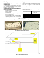
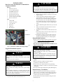
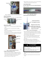
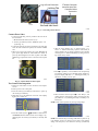
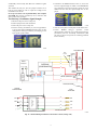
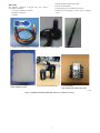
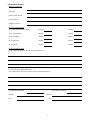
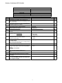
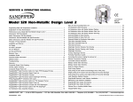
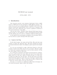
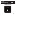
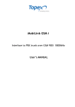
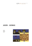
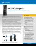
CRDMNDGW001A00 CRDMNDGW002A00 Energy Demand Gateway Rooftop Unit Accessory Installation Instructions INTRODUCTION C13331 NOTE: Read the entire instruction manual before starting the installation, and follow instructions carefully. Failure to do so may damage equipment, void warranties, or even cause serious injuries. SAFETY CONSIDERATIONS Improper installation, adjustment, alteration, service, maintenance, or use can cause explosion, fire, electrical shock, or other conditions which may cause death, personal injury or property damage. Consult a qualified installer, service agency or your distributor or branch for information or assistance. The qualified installer or agency must use factory--authorized kits or accessories when modifying this product. Refer to the individual instructions packaged with the kits or accessories when installing. Follow all safety codes. Wear safety glasses, protective clothing, and work gloves. Have a fire extinguisher available. Read these instructions thoroughly and follow all warnings and cautions included in literature and attached to the unit. Consult local building codes and the current edition of the National Electrical Code (NEC) NFPA 70. In Canada, refer to the current editions of the Canadian Electrical Code CSA C22.1. on Recognize safety information. When you see this symbol the unit and in instructions or manuals, be alert to the potential for personal injury. Understand the signal words DANGER, WARNING, and CAUTION. These words are used with the safety--alert symbol. DANGER identifies the most serious hazards, which will result in severe personal injury or death. WARNING signifies hazards, which could result in personal injury or death. CAUTION is used to identify unsafe practices, which may result in minor personal injury or product and property damage. NOTE is used to highlight suggestions which will result in enhanced installation, reliability, or operation. Carrierr’s Energy Demand System provides reliable and automated processes to manage the costs of energy consumption. Carrier’s Energy Demand System uses wireless devices incorporating patented Swarm Energy Management algorithms to create a network of coordinated rooftop units to reduce and optimize their energy usage. This system creates a wireless network of rooftop units with Energy Demand Load Controllers communicating through the Energy Demand Gateway. Each individual Load Controller can independently decide whether it should allow its unit to run by a relay that can break the connection between the rooftop unit and the thermostat. By communicating energy information through the Gateway, units are prevented from running simultaneously when it is not necessary, thereby smoothing out peak demand over time. This method provides the ability to accomplish Demand Management, Demand Response, and energy trending over time. Carrier offers two accessories that, when combined, make up the Energy Demand System. This technology utilizes Swarm Energy Managementt methodology as a basis for the operating sequence: S Energy Management Gateway (Coordinator) (Model Nos. CRDMNDGW001A00, CRDMNDGW002A00): This model is packaged with a cellular modem and modem enclosure, and is the first controller to be attached to a packaged rooftop unit and powered up. This controller will both monitor/control the attached rooftop unit, as well as act as a communications gateway back to the Swarm Energy Management Web Portal, a service provided by REGEN Energy, Inc.. Table 1 – Kit Voltage Requirements Kit No. CRDMNDGW001A00 CRDMNDGW002A00 Unit Voltage 208/230/460V 575V S Energy Demand Load Controller (Model Nos. CRDMNDMD001A00, CRDMNDMD002A00): This load controller is installed on the remaining packaged rooftop units that are to be monitored and controlled. NOTE: Please ensure you have the correct Installation Instructions for the given type of controller before continuing. INSTALLATION CONSIDERATIONS RTU Checklist Toward the end of this document, there is a RTU checklist that must be filled out for every Gateway (Coordinator) installed. The RTU checklist must be legible. The RTU checklists need to be scanned and emailed to [email protected] within 48 hours of the completion of the installation. Providing this checklist is vital to completing device set--up for operation. Wiring Diagram Equipment Location: A diagram noting all components and their proper wiring is provided. (See Fig. 11) The first step is to decide which rooftop unit should have the Gateway (Coordinator). This device should be mounted preferably in the middle of the rooftop or on a rooftop unit where other controllers have line of sight access to this rooftop unit. (See Fig. 1.) Installation Report An Installation Report is provided at the end of this document, where you should record installation notes for each Gateway (Coordinator), and issues encountered. Recommended Order of Operation To Install the Gateway (Coordinator): 1. 2. 3. 4. 5. 6. 7. Determine where to mount each component. Mount the components. Wire all components. Power up and test the Gateway (Coordinator). Fill out the required RTU Installation Checklist. Fill out the Installation Report. Scan and email “RTU Checklist” and “Installation Report” to [email protected] within 48 hours of completing device setup. Overview Schematic The components listed below must be installed. Refer to the diagram in Fig. 2. when deciding where to mount each component in relation to the rooftop unit. Component Installation Location Energy Demand Gateway (Coordinator) Inside cabinet Transformer Inside cabinet 4--Pole Relay Inside cabinet Modem Enclosure Exterior of cabinet Antenna and Mounting Base Exterior of cabinet, on top Preferred Location (Please note the central location on the rooftop) C13332 Fig. 1 -- Preferred Equipment Installation Locations Supplied 4-Pole Relay Supplied Transformer C13333 Fig. 2 -- Component Installation Schematic 2 INSTALLATION Basic list of tools and materials recommended to complete installation: Material S Small blue wire nuts S 9/16--in. Rubber grommet S #18 THHN standard wire S #18--22 fork connectors S #18--22 female connectors S #10 tek screws (3/4--in. long) S 5--1/2--in. And 7--1/2--in. zip ties S Tube of clear silicone Tools S Cordless drill S Control screw drivers S 1/4--in. Pilot bit S Nut drivers S Crimp tool S Wire strippers ! CAUTION CUT HAZARD Failure to follow this caution may result in personal injury. Sheet metal parts may have sharp edges or burrs. Use care and wear appropriate protective clothing and gloves when handling parts. 3. Determine where each component will be mounted: S Modem Enclosure: Mounted vertically, on a side of the cabinet’s exterior S Gateway (Coordinator): Mounted inside the cabinet, such that allows access to the keypad and display. Mounting location examples include, mounting within the unit control box, on a side wall within the unit, or any available panel. Ensure the selected mounting location does not cause damage to coils or existing components. S Antenna & Mounting Base: Mounted on top of the cabinet S Relay: Located inside the cabinet such that it reaches cooling and heating control lines S Transformer: Located inside the cabinet such that it can reach: a. Transformer primary--side wires will be attached to the rooftop unit’s load--side leads b. Transformer secondary--side wires will be attached to the Gateway (Coordinator) power wires (1 & 2) and modem power lines (24 & 25). See wiring diagram. Relay Transformer Mount Modem Enclosure: C13334 S Modem enclosure should be mounted vertically on an exterior fixed panel as close to the top of the cabinet as possible, in a position that allows the cover to be opened. S DO NOT MOUNT THE MODEM ENCLOSURE ON ANY REMOVABLE DOORS Fig. 3 -- Transformer and Relay Mounting Examples ! Suggested Installation Sequence ACCESSORY RELIABILITY HAZARD 1. Disable all power to the rooftop unit. ! Failure to follow this caution may result in accessory component damage. WARNING ELECTRICAL OPERATION HAZARD Failure to follow this warning could result in personal injury or death. S Disconnect power before opening unit. S ! WARNING S ELECTRICAL OPERATION HAZARD Failure to follow this warning could result in personal injury or death. Before installing, modifying, or servicing system, the main electrical disconnect switch must be in the OFF position. There may be more than one disconnect switch. Lock out and tag switch with a suitable warning label. 2. Open the main cabinet and control board cover CAUTION S Installation of Modem Enclosure on moveable doors may make it difficult or impossible to remove doors. This may also result in dropping the door and damaging the attached component or severing wires. Choose a side of the cabinet with the least exposure to the sun if possible. Ensure the enclosure’s cables can reach the Gateway (Coordinator)’s cable inside the cabinet. Pass the cables to the cabinet inside the rooftop unit using existing holes if available, or drill one so the cables can reach the control panel. Secure the cables using the black plastic gland (Hand--tighten). Mount Gateway (Coordinator): S Ensure the selected location for the Gateway (Coordinator) allows access to see the display & use the keypad. (See Fig.4 ) S Ensure extension wire from the Antenna Mounting Base can reach the top of the Gateway (Coordinator). S Securely mount the Gateway (Coordinator) using four of the Mounting Screws 3 S Plug the Molex connector pair from a CT to one of the matching connectors on the Gateway (Coordinator) cable. Coordinator Connect Data Cables Attach the 3--wire Molex connector from the Modem Enclosure to the 3--wire Molex connector from the Gateway (Coordinator) (wires 3, 4, 11, 12). C13339 Fig. 7 -- Data Cable Connection C13335 Fig. 4 -- Gateway (Coordinator) Mounting Examples Mount Transformer Install Antenna and Mounting Base Securely mount the transformer using 4 of the supplied mounting screws. (See Fig. 5) Secondary Side, 24V Primary Side Antenna attached to magnetic mount C13336 Fig. 5 -- Transformer Magnetic mount with extension wire passed inside cabinet, attached to top of controller Mount 4--Pole Relay S Securely mount the 4--pole relay using the 2 supplied mounting screws. S The 4--pole relay has a set of pre--kitted wires to simplify installation. S When the coil is energized, this will allow the control signals to pass on to the control board. S The rooftop unit’s Y1 and Y2, W1 and W2 control lines should be connected through the relays’ Normally Open control points (See Fig. 11) using the pre--kitted wires. C13340 S S 4-Pole Relay Transformer S S Coordinator Fig. 8 -- Antenna and Mounting Base Locate a smooth surface on the top of the cabinet to secure the Antenna and Antenna Mounting Base. Ensure there is sufficient slack on the extension cable to reach the Gateway (Coordinator) (mounted inside the cabinet). (See Fig. 8) Locate a small hole through which the antenna wire can pass into the cabinet (or drill a hole small enough for the wire). Ensure a 1/2--in. grommet is used to protect wiring from any sharp edges. Hand--tightened the Antenna to the Mounting Base. Hand--tighten the Mounting Base’s extension cable to the antenna mount on the top of the Gateway (Coordinator). Do not attach the antenna directly to the top of a Gateway (Coordinator). ! CAUTION ACCESSORY RELIABILITY HAZARD Failure to follow this caution may result in accessory component malfunction. C13337 The antenna must be installed outside of the rooftop unit cabinet to ensure signal broadcast and reception. Fig. 6 -- 4--Pole Relay Mounting Example Connect Current Sensors (CTS) S The two current sensors should be carefully clamped around different legs of the load--side leads, preferably L1 & L2 (L1 is often the leg powering single--phase fan motors; confirm via reading current with a clamp--on meter). (See Fig. 9) S Ensure the locking tabs are fully secured. S Glue the Antenna Mounting Base to the top of the rooftop unit using silicone to ensure it remains fixed even under heavy winds. S Use silicone to seal the hole where the antenna cable exits the cabinet. 4 2 Legs of Load-Side Leads Locking Tab CTs CT Molex Connector mated to one of the Controller Molex Connectors CT secured around the load-side leads C13338 Fig. 9 -- Connecting Current Sensors Connect Power Lines 1. Connect the following wires in parallel to the 24V side of the transformer: a. Modem Enclosure Power (wires 24, 25) b. Gateway (Coordinator) Power – RED Pair, (wires 1 & 2) (See Fig. 11) 2. Connect the primary side of the transformer to the load--side leads. If a wire extension is required, use stranded 18 AWG wire. 3. When you power up the Gateway the green WAN light & green power light should be solid within one minute of power up. If these lights do not come on please contact REGEN Energy’s Operations Center at 949--258--4415, Option #2. C13343 6. After the screen displays “rly”, it will then show “1 2”, where: “1” indicates that Relay 1 (blower control line) is closed (Applies only for Energy Demand Load Controller Accessory) and “2” indicates that Relay 2 (cooling and heating control lines) is closed. C13344 7. Press B to open Relay 2 and confirm that the compressor(s) turn off (after waiting for any minimum startup runtime delays). The display will show “1 –“, indicating that Relay 1 is still closed, yet Relay 2 is now open. C13341 Fig. 10 -- Modem WAN and Power lights Test Control Line Integration 1. Jumper the control lines to force the blower and compressors on. 2. Restore power to the rooftop unit. 3. Press the Gateway (Coordinator)’s ON button to power up the Gateway (Coordinator). 4. Wait until you see the indicators on the left of the display light up in a vertical row. C13345 C13345 8. Wait 20 minutes and then press B to close Relay 2, and confirm that the compressor(s) resume operation. The display will show“1 2”, indicating that Relay 1 and Relay 2 are both closed. NOTE: Some control systems may have up startup delays C13342 5. Press the unlock sequence: Y,B, ENTER. Confirm that the OVERRIDE indicator flashes and the screen displays “rly”, indicating that the Gateway (Coordinator) is in Relay Test Mode. C13344 NOTE: The selected relay test settings will remain in place for up to 20 minutes, and up to 10 changes can be made to relay settings during each Relay Test, after which the Gateway (Coordinator) 5 5. Confirm that the READY indicator turns on, and at least two bars of signal strength are visible. Contact REGEN Energy’s Operation Center (949--258--4415, Option No. 2) for assistance if fewer than two signal strength bars are displayed. automatically exits the Relay Test Mode and commences regular operation. After finished the relay test, leave the jumpers connected for at least five more minutes in order to capture the readings for the maximum load of the unit. Do not proceed to the next step until the Relay Test completes successfully. The Gateway (Coordinator) can be restarted in Test mode as many times as desired. Test Gateway (Coordinator) Signal Strength 1. 2. 3. 4. Disconnect all power to the rooftop unit. Remove jumper wires from control lines. Restore all power to the rooftop unit. Turn the Gateway (Coordinator) on, and wait approximately 20 seconds until the TRAFFIC indicator turns on, indicating that the Gateway (Coordinator) is attempting to boot up in regular operation mode C13360 6. Close the rooftop unit’s control panel and all cabinet doors. 7. Contact REGEN Energy’s Operation Center (949--258--4415, Option No. 2) to notify that the Gateway (Coordinator) has been successfully commissioned (This step does not need to be repeated for each Energy Demand Load Controller). C13359 Load-Side Power Molex connector CT Clamp Sensor 1 7 CT Clamp Sensor 2 8 Modem Enclosure GND PWR 9 10 GATEWAY (COORDINATOR) RS232 575V 480V 2 Stepdown Trasformer Molex connector 24VAC12VDC Transformer 12 11 4 3 6 5 WIRE NUT CONNECTION 24V 1 24 25 FIELD INSTALLED WIRE Controls Terminal Board 18 W2 19 Y1 20 6 7 8 21 9 5 Omron LY4 Four pole Relay W1 From Thermostat 13 14 W1 15 W2 16 Y1 17 Y2 10 11 12 14 FIELD INSTALLED WIRE C13361 Fig. 11 -- Standard Wiring Schematic for Thermostat Controls (2--Stage Unit) 6 Parts List 4. 5. 6. 7. The following equipment is shipped with each Gateway (Coordinator) Accessory. 1. Gateway (Coordinator) Controller 2. Magnetic antenna base 3. Antenna Modem enclosure (with modem inside) (2) Current Transformers 4--Pole Relay (pre--wired with extension wires) Mounting screws (supplied in a plastic bag, not displayed below 1. Gateway (Coordinator) Controller 2. Magnetic antenna base 4. Modem Enclosure (with modem inside) 5. (2) Current Transformers 3. Antenna 6. 4-Pole Relay (pre-wired with extension wires) C13362 Fig. 12 -- Supplied Parts included with Each Gateway (Coordinator) Accessory 7 Site Installation Report Section 1.- Site Summary Customer Name Site Address Customer Phone Number Customer Email Installation Contractor Section 2.- Installation Details Qty. of Modems/Gateways (Coordinators) Shipped Installed Qty. of Load Controllers Shipped Installed Qty. of 4-Pole Relays Shipped Installed Qty. of Transformers Shipped Installed Qty. of Antennas Shipped Installed Section 3.- Installation Issues Facility Roof Access Delays: (Ex.: Security, Escort. Clearances, etc.) List of any RTU #s not operational/disrepair: (Ex.: RTUs shut down, locked out for service, obvious mechanical problems, etc.) Customer Name (Print Name) Signature Installer Name (Print Name) Signature Date Date 8 Gateway (Coordinator) RTU Checklist Gateway (Coordinator) Installation Checklist Site RTU #, Zone Name Controller ID Today’s Date Installer Name REGEN Energy Operations Center/Support- (949) 258-4415, Option #2 Step Notes 1 Power off RTU 2 Install Gateway (Coordinator) and components, incl. wiring. Install Modem Enclosure, wire to Gateway (Coordinator) inside cabinet. 3 Connect test jumper wires: R to lines on relay that will be connected to original G, Y1, Y2 lines. 4 Glue antenna base, caulk any drilled openings 5 Pause if need to return to previous RTU after waiting for portal test, note time 6 Power up RTU 7 Confirm modem WAN light is on within one min. After power up 8 Wait until blower and all stages of cooling are energized, note any startup delays Blower Delay 1st stage Delay 2nd stage Delay 9 Once all stages of cooling energized, measure amperage on lines where CTs are clamped, measure incoming voltage Incoming Voltage: 277/480/120/208 CT1 Amps: CT2 Amps: 10 Perform relay test UP, DOWN, ENTER Factor in any blower/compressor min. run times and start delays, note any shutdown delays Blower Delay: 111 Exit the relay test to start regular operation 12 Confirm READY indicator and at least two bars of signal strength. Change Zigbee channel if directed by REGEN support. UP, DOWN, UP, UP, ENTER Note time 13 Move to next RTU, waiting at least 20 min. to return 14 When you return, power off RTU 15 Remove jumper wires and dress wiring (e.g. tie wraps, sticky backs) 16 Power up RTU & confirm controller connects to network (Confirm READY indicator and at least two bars of signal strength) Time Paused: Time Resumed: Channel (default of 11 or new value): # of bars: 9 Copyright 2013 Carrier Corp. S 7310 W. Morris St. S Indianapolis, IN 46231 Edition Date: 05/13 Manufacturer reserves the right to change, at any time, specifications and designs without notice and without obligations. 10 Catalog No: CRDMNDGW001---01IIK Replaces: NEW