1
SAMSUNG Home Appliance Service
SIDE-BY-SIDE REFRIGERATOR
MODEL:
RS2511
RS2611
RS2630W/XAA
RS2531
RS2631
RS2521
RS2621
RS2630SW
WARNING
IMPORTANT SAFETY NOTICE
The service guide is for service men with adequate backgrounds of
electrical, electronic, and mechanical experience. Any attempt to repair
a major appliance may result in personal injury and property damage.
The manufacturer or dealer cannot be responsible for the interpretation
of this information.
SAMSUNG ELECTRONICS AMERICA, INC.
Technical Service Guide
Copyright ⓒ2004
All rights reserved. This service guide may not be reproduced in whole or in
part in any form without written permission from the SAMSUNG ELECTRONICS
Company.
2
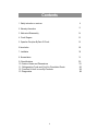
Contents
1. Safety instruction on services ∙∙∙∙∙∙∙∙∙∙∙∙∙∙∙∙∙∙∙∙∙∙∙∙∙∙∙∙∙∙ 4
2. Warranty information
∙∙∙∙∙∙∙∙∙∙∙∙∙∙∙∙∙∙∙∙∙∙∙∙∙∙∙∙∙∙∙∙∙∙∙9
3. Mechanical Disassembly
∙∙∙∙∙∙∙∙∙∙∙∙∙∙∙∙∙∙∙∙∙∙∙∙∙∙∙∙∙∙∙∙14
4. Circuit Diagram ∙∙∙∙∙∙∙∙∙∙∙∙∙∙∙∙∙∙∙∙∙∙∙∙∙∙∙∙∙∙∙∙∙∙∙∙∙∙15
5. Operation Principles By Parts Of Circuit ∙∙∙∙∙∙∙∙∙∙∙∙∙∙∙∙∙∙∙∙∙∙∙∙16
6.Introduction
∙∙∙∙∙∙∙∙∙∙∙∙∙∙∙∙∙∙∙∙∙∙∙∙∙∙∙∙∙∙∙∙∙29
7. Installation
30
8. Nomenclature
31
9. Specifications
10. Interior Views and Dimensions
11. Refrigeration Cycle and Cool Air Circulation Route
12. Function & How- to-use By Products
13. Diagnostics
32
33
36
38
58
3
1. Safety Instructions on Service
●Unplug the refrigerator before making any repair or any replacement.
� Avoid the electric shock.
●Use the rated components on the replacement.
� Check the correct model number, rated voltage, rated current, operating temperature and so
on.
●On repair, be sure that the wires such as harness are bundled tightly and are not exposed by
water.
� Bundle wires tightly in order not to be detached by the external force.
●On repair, remove completely dust, particles or other things on housing parts, harness parts,
and connectors.
� Cleaning may prevent fire by tracking or short.
●Check if there is any trace indicating the infitration of water on electrical parts.
� If there is kind of trace, change the related components or do the necessary action
such as taping using the insulating tape.
●After repair, check the assembled state of parts.
� It must be in the same assembled state when compared with the state before
disassembly.
●Check the surrounding conditions of the installed refrigerator.
� When the refrigerator is located at humid or wet place, or the installed state is
unstable, change the location.
●If needed, do the ground.
� Especially, if there is a possibility of the electric leakage, this appliance must be
properly grounded.
●Do not allow consumers to use one outlet for several plugs.
●Check whether the power cord is placed under other appliance and so, damaged, worm-out
squeezed.
�Repair immediately the defective power plug or outlet.
�Make sure that the power cord is not placed under other appliance or squeezed.
●Do not allow consumers to keep bottles or the likes in the Freezer or to keep foods in unstable
position.
●Do not allow consumers to repair the appliance by themselves.
●Do not allow consumers to keep other chemicals except food.
�Medicines and other materials for research ; This appliance will not maintain the precisely
constant temperature for them.
�Volatile material(Alcohol, Benzene, Ether, LP gas etc.) : possibility of explosion
4
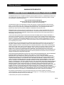
2. Warranty information
SAMSUNG REFRIGERATOR
LIMITED WARRANTY TO ORIGINAL PURCHASER
This SAMSUNG brand product, as supplied and distributed by Samsung Electronics America, Inc. (SAMSUNG) and delivered new,
in the original carton to the original consumer purchaser, is warranted by SAMSUNG against manufacturing defects in materials
and workmanship for a limited warranty period of:
One (1) Year Parts and Labor on Refrigerator
Five (5) Years Parts and Labor on Sealed Refrigeration System Only*
(*Compressor, evaporator, condenser, drier, connecting tubing)
This limited warranty begins on the original date of purchase, and is valid only on products purchased and used in the United
States. To receive warranty service, the purchaser must contact SAMSUNG for problem determination and service procedures.
Warranty service can only be performed by a SAMSUNG authorized service center. The original dated bill of sale must be
presented upon request as proof of purchase to SAMSUNG or SAMSUNG's authorized service center.
SAMSUNG will repair or replace any part found to be defective, at our option and at no charge as stipulated herein, with new or
reconditioned parts during the limited warranty period specified above. All replaced parts and products become the property of
SAMSUNG and must be returned to SAMSUNG. Replacement parts and products assume the remaining original warranty, or
ninety (90) days, whichever is longer.
In-home service will be provided during the warranty labor period subject to availability within the contiguous United States. Inhome service is not available in all areas. To receive in-home service, the product must be unobstructed and accessible from floor
level to service personnel. If during in-home service repair cannot be completed, it may be necessary to remove, repair and return
the product. If in-home service is unavailable, SAMSUNG may elect, at our option, to provide for transportation of our choice to
and from a SAMSUNG authorized service center. Otherwise, transportation to and from the SAMSUNG authorized service center
is the responsibility of the purchaser.
This limited warranty covers manufacturing defects in materials and workmanship encountered in normal, noncommercial use of
this product, and shall not apply to the following, including, but not limited to: damage which occurs in shipment; delivery and
installation; applications and uses for which this product was not intended; altered product or serial numbers; cosmetic damage or
exterior finish; accidents, abuse, neglect, fire, water, lightning or other acts of nature; use of products, equipment, systems, utilities,
services, parts, supplies, accessories, applications, installations, repairs, external plumbing and leaks, external wiring, circuit
breakers, fuses or connectors not supplied and authorized by SAMSUNG, or which damage this product or result in service
problems; incorrect electrical line voltage, fluctuations and surges; customer adjustments and failure to follow operating instructions,
cleaning, maintenance and environmental instructions that are covered and prescribed in the instruction book; loss of food due to
spoilage; consumable items including filters and light bulbs.
THERE ARE NO EXPRESS WARRANTIES OTHER THAN THOSE LISTED AND DESCRIBED ABOVE, AND NO WARRANTIES
WHETHER EXPRESS OR IMPLIED, INCLUDING, BUT NOT LIMITED TO, ANY IMPLIED WARRANTIES OF
MERCHANTABILITY OR FITNESS FOR A PARTICULAR PURPOSE, SHALL APPLY AFTER THE EXPRESS WARRANTY
PERIODS STATED ABOVE, AND NO OTHER EXPRESS WARRANTY OR GUARANTY GIVEN BY ANY PERSON, FIRM OR
CORPORATION WITH RESPECT TO THIS PRODUCT SHALL BE BINDING ON SAMSUNG. SAMSUNG SHALL NOT BE
LIABLE FOR LOSS OF REVENUE OR PROFITS, FAILURE TO REALIZE SAVINGS OR OTHER BENEFITS, OR ANY OTHER
SPECIAL, INCIDENTAL OR CONSEQUENTIAL DAMAGES CAUSED BY THE USE, MISUSE OR INABILITY TO USE THIS
PRODUCT, REGARDLESS OF THE LEGAL THEORY ON WHICH THE CLAIM IS BASED, AND EVEN IF SAMSUNG HAS BEEN
ADVISED OF THE POSSIBILITY OF SUCH DAMAGES. NOR SHALL RECOVERY OF ANY KIND AGAINST SAMSUNG BE
GREATER IN AMOUNT THAN THE PURCHASE PRICE OF THE PRODUCT SOLD BY SAMSUNG AND CAUSING THE
ALLEGED DAMAGE. WITHOUT LIMITING THE FOREGOING, PURCHASER ASSUMES ALL RISK AND LIABILITY FOR LOSS,
DAMAGE OR INJURY TO PURCHASER AND PURCHASER’S PROPERTY AND TO OTHERS AND THEIR PROPERTY
ARISING OUT OF THE USE, MISUSE OR INABILITY TO USE THIS PRODUCT SOLD BY SAMSUNG NOT CAUSED DIRECTLY
BY THE NEGLIGENCE OF SAMSUNG. THIS LIMITED WARRANTY SHALL NOT EXTEND TO ANYONE OTHER THAN THE
ORIGINAL PURCHASER OF THIS PRODUCT, IS NONTRANSFERABLE AND STATES YOUR EXCLUSIVE REMEDY.
Some states do not allow limitations on how long an implied warranty lasts, or the exclusion or limitation of incidental or
consequential damages, so the above limitations or exclusions may not apply to you. This warranty gives you specific legal rights,
and you may also have other rights, which vary from state to state.
To obtain warranty service, please contact SAMSUNG at:
061002
5
3. Mechanical Disassembly
3-1) Refrigerator Disassembly
Control Panel ∙∙∙∙∙∙∙∙∙∙∙∙∙∙∙∙∙∙∙∙∙∙∙∙∙∙∙∙∙∙∙∙∙∙∙∙∙∙∙∙ 7
Door Handle ∙∙∙∙∙∙∙∙∙∙∙∙∙∙∙∙∙∙∙∙∙∙∙∙∙∙∙∙∙∙∙∙∙∙∙∙∙∙∙∙∙ 7
Door Gasket ∙∙∙∙∙∙∙∙∙∙∙∙∙∙∙∙∙∙∙∙∙∙∙∙∙∙∙∙∙∙∙∙∙∙∙∙∙∙∙∙∙ 7
Refrigerator Door Light Switch ∙∙∙∙∙∙∙∙∙∙∙∙∙∙∙∙∙∙∙∙∙∙∙∙∙∙∙∙∙∙∙ 7
Refrigerator Light ∙∙∙∙∙∙∙∙∙∙∙∙∙∙∙∙∙∙∙∙∙∙∙∙∙∙∙∙∙∙∙∙∙∙∙∙∙∙ 8
Tempered Glass Shelf ∙∙∙∙∙∙∙∙∙∙∙∙∙∙∙∙∙∙∙∙∙∙∙∙∙∙∙∙∙∙∙∙∙∙∙ 8
Plastic Drawers in Refrigerator ∙∙∙∙∙∙∙∙∙∙∙∙∙∙∙∙∙∙∙∙∙∙∙∙∙∙∙∙∙∙ 8
Gallon Door Bin ∙∙∙∙∙∙∙∙∙∙∙∙∙∙∙∙∙∙∙∙∙∙∙∙∙∙∙∙∙∙∙∙∙∙∙∙∙∙∙ 8
Water Filter ∙∙∙∙∙∙∙∙∙∙∙∙∙∙∙∙∙∙∙∙∙∙∙∙∙∙∙∙∙∙∙∙∙∙∙∙∙∙∙∙∙ 8
Damper in the Refrigerator ∙∙∙∙∙∙∙∙∙∙∙∙∙∙∙∙∙∙∙∙∙∙∙∙∙∙∙∙∙∙∙∙ 9
Twin cool in the Refrigerator ∙∙∙∙∙∙∙∙∙∙∙∙∙∙∙∙∙∙∙∙∙∙∙∙∙∙∙∙∙∙∙ 9
Refrigerator Thermistor ∙∙∙∙∙∙∙∙∙∙∙∙∙∙∙∙∙∙∙∙∙∙∙∙∙∙∙∙∙∙∙∙∙∙ 9
3-2) Freezer Disassembly
Door Bin in Freezer ∙∙∙∙∙∙∙∙∙∙∙∙∙∙∙∙∙∙∙∙∙∙∙∙∙∙∙∙∙∙∙∙∙∙∙∙ 10
Freezer Door Light Switch ∙∙∙∙∙∙∙∙∙∙∙∙∙∙∙∙∙∙∙∙∙∙∙∙∙∙∙∙∙∙∙∙∙ 10
Plastic(Wire) Drawer in Freezer ∙∙∙∙∙∙∙∙∙∙∙∙∙∙∙∙∙∙∙∙∙∙∙∙∙∙∙∙∙∙ 10
Freezer Shelf ∙∙∙∙∙∙∙∙∙∙∙∙∙∙∙∙∙∙∙∙∙∙∙∙∙∙∙∙∙∙∙∙∙∙∙∙∙∙∙∙ 10
Ice Dispenser & Ice Maker ∙∙∙∙∙∙∙∙∙∙∙∙∙∙∙∙∙∙∙∙∙∙∙∙∙∙∙∙∙∙∙∙ 10
Auger Motor Case ∙∙∙∙∙∙∙∙∙∙∙∙∙∙∙∙∙∙∙∙∙∙∙∙∙∙∙∙∙∙∙∙∙∙∙∙∙ 11
Freezer Light ∙∙∙∙∙∙∙∙∙∙∙∙∙∙∙∙∙∙∙∙∙∙∙∙∙∙∙∙∙∙∙∙∙∙∙∙∙∙∙∙ 12
Evaporator Cover in Freezer ∙∙∙∙∙∙∙∙∙∙∙∙∙∙∙∙∙∙∙∙∙∙∙∙∙∙∙∙∙∙∙∙ 12
Evaporator Fan Motor ∙∙∙∙∙∙∙∙∙∙∙∙∙∙∙∙∙∙∙∙∙∙∙∙∙∙∙∙∙∙∙∙∙∙∙ 12
Evaporator in Freezer ∙∙∙∙∙∙∙∙∙∙∙∙∙∙∙∙∙∙∙∙∙∙∙∙∙∙∙∙∙∙∙∙∙∙∙ 13
Freezer Thermistor ∙∙∙∙∙∙∙∙∙∙∙∙∙∙∙∙∙∙∙∙∙∙∙∙∙∙∙∙∙∙∙∙∙∙∙∙∙ 13
Ambient Thermistor ∙∙∙∙∙∙∙∙∙∙∙∙∙∙∙∙∙∙∙∙∙∙∙∙∙∙∙∙∙∙∙∙∙∙∙∙∙ 13
Ice-Maker Thermistor ∙∙∙∙∙∙∙∙∙∙∙∙∙∙∙∙∙∙∙∙∙∙∙∙∙∙∙∙∙∙∙∙∙∙∙∙ 13
3-3) Machine Compartment Disassembly
Machine Compartment & Electrix Box ∙∙∙∙∙∙∙∙∙∙∙∙∙∙∙∙∙∙∙∙∙∙∙∙∙∙14
Water Solenoids ∙∙∙∙∙∙∙∙∙∙∙∙∙∙∙∙∙∙∙∙∙∙∙∙∙∙∙∙∙∙∙∙∙∙∙∙∙∙14
Condenser Fan ∙∙∙∙∙∙∙∙∙∙∙∙∙∙∙∙∙∙∙∙∙∙∙∙∙∙∙∙∙∙∙∙∙∙∙∙∙∙∙14
Sub-condenser ∙∙∙∙∙∙∙∙∙∙∙∙∙∙∙∙∙∙∙∙∙∙∙∙∙∙∙∙∙∙∙∙∙∙∙∙∙∙∙14
6
3. Mechanical Disassembly
3-1) Refrigerator Disassembly
Control Panel
Door Gasket
1. Insert a flat-blade screwdriver on the slot as shown,
and unlock the tabs.
2. Disconnect the wire connector.
The door gasket is a molded gasket set into a
channel located in the door liner.
1. Open the door.
2. Grasp the gasket and pull in an outward motion
until the molded gasket separates from the door
liner.
Door Handle
The door handles allow access into the refrigerator
and freezer. They are front mounted with Phillips
head screws.
1. With a small flat-blade screwdriver, press the
small button and pull handle cover out.
2. Remove the Phillips screws (5).
3. Lift the handle with an in and upward motion until
it disengages the locking tabs. Pull the handle
outward to remove it.
Refrigerator Door Light Switch
The refrigerator has a door light switch located in
the upper right corner for the refrigerator.
1. Use a small flat-blade screwdriver to unlock the
locking tab and pull the switch out until the
wire connector is visible.
Button
7
Mechanical Disassembly
Refrigerator Light
The refrigerator light is located in the upper portion
of refrigerator.
1. Pull the tip on the cover.
Gallon Door Bin
The door bins allow storage of perishable items.
1. Push the bin up and slide it out.
Tempered Glass Shelf
These shelves allow the storage of larger items and
pull out for easy access.
1. Pull the shelf out as far as it goes.
2. Lift it up and remove it.
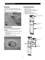
Water Filter
The water filter is located in the bottom left-hand
corner of the refrigerator. The water filter filters water
for the ice maker and the water dispenser.
1. Turn the water filter 1/2 turn counterclockwise and
pull it down.
2. To install the filter, align the indication mark
(unlock position) and push it up while turning 1/2
turn clockwise until the lock position is aligned.
Do not over tighten.
Plastic Drawers in Refrigerator
Drawers are designed for storage of fruits,
vegetables, and deli items. The drawers are located
in the lower portion of the refrigerator.
1. Pull out the drawer as far as it goes.
2. Tilt the drawer up and pull it out until it is
removed.
8
Mechanical Disassembly
Damper in the Refrigerator
1. Pull out the screw cap and remove the screw.
2. Remove the lamp cover by unlocking the tabs
and pulling the cover down.
3. Remove the screw at the cover damper.
4. Take off sensor and lamp wire connector located
on the upper liner.
6. Remove the damper from the refrigerator.
Refrigerator Thermistor
The refrigerator thermistor is located inside of the
upper light cover of the refrigerator.
THERMISTOR
Twin cool in the Refrigerator
1. Pull out the Twin cool by unlocking the hooks.
9
Mechanical Disassembly
3-2) Freezer Disassembly
Door Bin in Freezer
The door bins allow storage of perishable items.
1. Push the bin up and slide it out.
Freezer Shelf
The shelves slide out for easy access for frozen
items.
1. Slide the shelf out until it reaches its stop.
2. Tilt down and slide it out of the compartment.
Freezer Door Light Switch
This switch is located in the left-hand portion of the
freezer and sends a signal to the processor.
1. With a small flat-blade screwdriver, unlock the
locking tabs and pull the switch out until the wire
connector is visible.
2. Disconnect the wire connector and remove the
switch.
Plastic (Wire) Drawer in Freezer
Drawers are designed for storage of meat and dry
foods. The drawers are located in the lower portion of
the freezer.
1. Pull out the drawer as far as it goes.
2. Tilt the drawer up and pull it out until it is
removed.
10
Mechanical Disassembly
top of the liner, and slide the ice maker in.
5. Tighten the screws (2) of the ice maker support.
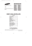
Ice Dispenser & Ice Maker
The ice dispenser is located in the upper portion of
the freezer. This assembly stores ice made by the
icemaker and dispenses ice.
1. Lift the ice bucket up ① and slide out the ice
dispenser assembly ②.
FRONT LOCKING TAB
TAB HOLES
FRONT OF ICE TRAY
GEARED MOTOR SHAFT
Auger Motor Case
This shelf is designed to support the ice maker &
ice dispensed and Xtra SpaceTM.
1. Remove the Xtra SpaceTM cover to push it down
and pull front.
2. Slide the partition out.
3. Remove the screws (2) on the bottom front of the
case.
4. Slide out the case while disconnecting the wire
connect.
The ice maker is located inside of the ice dispenser
assembly.
1. Remove ice maker support screws (2), and slide out.
2. Disconnect the ice maker wire connector.
3. Unlock the locking tabs to separate the ice maker kit.
SUPPORT OF ICE-MAKER
LOCKING TAB
PARTITION
WIRE CONNECTOR
ICE-MAKER KIT
In order to assemble the icemaker kit.
1. Assemble the geared motor shaft and the front of
ice tray.
2. Lift the front locking tab and assemble the ice
maker kit.
3. Connect the ice maker wire connector.
4. Match the tab holes and tabs(2) located on the
SCREWS
11
Mechanical Disassembly
Freezer Light
Evaporator Cover in Freezer
The freezer light is located in the bottom of the
auger motor case. The light is covered by an opaque
cover.
1. Remove the screw and the light cover.
1. Remove screw (6).
2. Remove the assy cover multi fre.
3. Remove the assy cover supt motor fre.
4. Remove screw (2).
5. Remove the cover evap front.
6. Disconnect the sensor wire connector.
ASSY COVER MULTI FRE
ASSY COVER SUPT
MOTOR FRE
Evaporator Fan Motor
The evaporator fan is located in the middle rear of
refrigerator. This fan circulates cold air in the
refrigerator.
1. Remove the fan spring, and than remove fan and
protector motor.
2. Remove screw located at the four corners of
the fan bracket.
3. Take the fan motor assembly off.
COVER EVAP FRONT
INS MULTI FRE
INS SUPT
MOTOR FRE
12
Mechanical Disassembly
Evaporator in Freezer
Evaporator is located in the bottom of freezer to
produce cold air driven across the evaporator coils.
1. Take off the ductwork in Freezer.
2. Disconnect the wire connector (Heater, Bimental,
and Thermistor).
3. Desolder the inlet and outlet tubes.
4. Remove the evaporator.
5. Take the same steps to seal the system as
mentioned earlier.
THERMISTOR
Ice-MakerThermistor
The Ice-Maker thermistor is located in its bottom.
The temperature signal sends the micro-processor.
THERMISTOR
Freezer Thermistor
The freezer thermistor is located at the top left of
freezer vent. It sends temperature signals to the
micro-processor.
13
Mechanical Disassembly
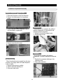
3-3) Machine Compartment Disassembly
Machine Compartment & Electric Box
1. Disconnect the power cord of the refrigerator.
2. Remove the fixed screws (6) of compressor
cover.
Condenser Fan
The condenser Fan is located in the middle of
machine compartment. It cools down the subcondenser and the compressor.
1. Lift up the rib under the support motor.
2. Pull the support motor.
3. Slide up and take off the compressor cover to
see the machine compartment.
4. Remove screw (2) on the cover.
Condenser
The condenser is located in the machine
compartment. The heat is extracted by condenser
fan.
1. Desolder the compressor discharge &the
condenser outlet.
2. Take out the condenser.
Water Solenoids
When the solenoids receive a signal from the microprocessor, they supply water to the water dispenser
or the ice maker.
1. Remove bracket screw on cabinet.
2. Take the solenoids assembly out.
3. Disconnect water tubes.
14
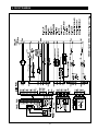
4. CIRCUIT DIAGRAM
15
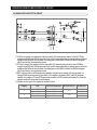
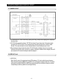
5. OPERATION PRINCIPLES BY PARTS OF CIRCUIT
5-1) POWER
Terminal
Oscillation Frequency
● Vcc(DC 5V)
MICOM POWER AND SENSORS
<< BLDC
BLDC MOTOR POWER(NOT USE)
+12V(DC 12V)
RELAY,PANEL POWER
● When turned on, rectified AC voltage which is stepped down on 2nd transformer flows between ① and ③
at about AC 15V, goes through the diode D101 and D104 is changed to DC, and provide constant 12V.
It provides 5V to MICOM and other circuits via regulator REG102 (MC7805ACT), and make entire PCB
operate.
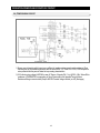
5-2) OSCILLATION CIRCUIT
Terminal
Oscillation Frequency
Xin(#19)
8.0MHz
Xout(#18)
8.0MHz
● It is an Oscillation Circuit for synchronism clock generation and time calculation on the information sending &
receiving of the MICOM internal logic elements and when specifications for Resonator change, the timing
system of MICOM changes resulting in errors. (Rated parts must be used)
16
OPERATION PRINCIPLES BY PARTS OF CIRCUIT
5-3) RESET CIRCUIT
●
RESET Circuit allows the whole program to go back to the initial setting by initializing parts such as the RAM in
MICOM with the power supply into MICOM or with an instant power failure.
Upon the power supply, the reset terminal voltage becomes "LOW" for several tens of ㎲ compared to Vcc
voltage(DC 5V) at MICOM, and it maintains "HIGH"(Vcc Voltage) during normal operation.
But, when Vcc drops down to 3.4~3.7V, the reset terminal voltage becomes "LOW".
5-4) EEPROM DETECTION CIRCUIT
●
A semiconductor memory EEPROM stores data remembering previous settings regardless of power-off, which
are indispensable especially in power fluctuating areas. Also, EEPROM sets and uses other options in principle.
17
OPERATION PRINCIPLES BY PARTS OF CIRCUIT
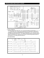
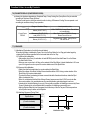
5-5) DOOR SWITCH DETECTON CIRCUIT
1) If R-Door is opened, the contact point of the door switch (4-3) becomes open, and the current of PCB line
comes through R404 and R405 and provides 5 volt which is recognized as door is opened, and turn off the fan
at different load. When the door is closed, the voltage goes out from R404 to Switch, the MICOM is applied
with OV and the door is recognized as closed.
2) If F-Door is opened, the contact point of the door switch (4-3) becomes open, and the current of PCB line
comes through R402 and R403 and provides 5 volt which is recognized as door is opened, and turn off the fan
at different load. When the door is closed, the voltage goes out from R402 to Switch, the MICOM is applied
with OV and the door is recognized as closed.
3) Q401 is the circuit to turn off the auger motor operation when the door is opened. If the door is closed, Vcc
voltage of R402 works as ground via door switch, OV is applied to the base of Q401, and Q401 becomes
operable, Vcc voltage on "A" part Q702 base works as emitter on Q401 collector and creates OV. (Check the
operable condition for other parts at load terminals)
4) Condition for door open is the opposite of condition 3 above.
Category
F
R
Door
DOOR S/W Contact Point
CLOSE
OPEN
CLOSE
OPEN
CLOSE
OPEN
CLOSE
OPEN
18
MICOM PORT NO
#50
#49
MICOM INPUT
"LOW"
"HIGH"
"LOW"
"HIGH"
OPERATION PRINCIPLES BY PARTS OF CIRCUIT
5-6) TEMP SENSING CIRCUIT
1) Sensor uses a thermistor which has a temp coefficient of negative resistance and controls resistance. When
the heat goes up, the resistance gets down and vice versa. R302, 4, 6, 9 and C301~C303, C305 are parts for
noise prevention but they are not related to temp sensing characteristics.
2) If Vf is the incoming voltage to MICOM in case of F-Sensor, Vf equals (Rth * Vcc)/ ((R301 + Rth). Where Rth is
resistance of THERMISTOR corresponding to Temp. Please refer to the Appendix Temp-to-Sensor
Resistance/Voltage conversion table(Temp-to-MICOM Terminal Voltage included) on A/S. (Next page)
19
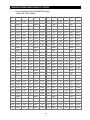
OPERATION PRINCIPLES BY PARTS OF CIRCUIT
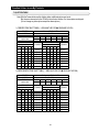
� Temp to Resistance of Sensor & MICOM PORT Voltage
Sensor CHIP : PX41C Standard
Temp. Resistance(㏀) Voltage(V) Temp. Resistance(㏀) Voltage(V) Temp. Resistance(㏀) Voltage(V) Temp. Resistance(㏀) Voltage(V)
-50 °F/-45.6 °C 153319
-49 °F/-45.0 °C 144794
4.694
-48 °F/-44.4 °C 136798
-47°F/-43.9 °C 129294
4.659
-46 °F/-43.3 °C 122248
-45 °F/-42.8 °C 115631
4.622
-44 °F/-42.2 °C 109413
-43°F/-41.7 °C 103569
4.581
-42°F/-41.1 °C 98073
-41°F/-40.6 °C 92903
4.537
-40°F/-40.0 °C 88037
-39°F/-39.4 °C 83456
4.49
4.677
4.641
4.602
4.56
4.514
4.465
-19°F/-28.3°C 30752
-18°F/-27.8 °C 29350
3.773
12°F/-11.1°C
8200
2.253
43°F/6.1 °C
2714
1.068
3.729
13°F/-10.6°C
7888
2.205
44°F/6.7 °C
2627
1.04
-17°F/-27.2 °C 28021
-16°F/-26.7 °C 26760
3.685
2.158
45°F/7.2 °C
2543
1.014
3.64
14°F/-10.0°C 7590
15°F/-9.4°C 7305
2.111
46°F/7.8 °C
2462
0.988
-15°F/-26.1 °C 25562
-14°F/-25.6 °C 24425
3.594
16°F/-8.9°C
7032
2.064
47°F/8.3 °C
2384
0.963
3.548
17°F/-8.3°C
6771
2.019
48°F/8.9 °C
2309
0.938
-13°F/-25.0 °C 23345
-12°F/-24.4 °C 22320
3.501
18°F/-7.8°C
6521
1.974
49°F/9.4 °C
2237
0.914
3.453
19°F/-7.2°C
6281
1.929
50°F/10.0°C
2167
0.891
-11°F/-23.9 °C 21345
-10°F/-23.3 °C 20418
3.405
20°F/-6.7°C
6052
1.885
51°F/10.6 °C
2100
0.868
3.356
21°F/-6.1°C
5832
1.842
52°F/11.1 °C
2036
0.846
-9°F/-22.8 °C 19537
-8°F/-22.2 °C 18698
3.307
22°F/-5.6°C
5621
1.799
53°F/11.7 °C
1973
0.824
3.258
23°F/-5.0°C
5419
1.757
54°F/12.2 °C
1913
0.803
-7°F/-21.7 °C 17901
-6°F/-20.6 °C 17142
3.208
24°F/-4.4°C
5225
1.716
55°F/12.8 °C
1855
0.783
3.158
25°F/-3.9°C
5000
1.675
56°F/13.3 °C
1799
0.762
-5°F/-20.0 °C 16419
-4°F/-45.6 °C 15731
3.107
26°F/-3.3°C
4861
1.636
57°F/13.9 °C
1745
0.743
3.057
27°F/-2.8°C
4690
1.596
58°F/14.4 °C
1693
0.724
-3°F/-19.4 °C 15076
-2°F/-18.9 °C 14452
3.006
28°F/-2.2°C
4526
1.558
59°F/15.0 °C
1642
0.706
2.955
29°F/-1.7°C
4369
1.52
60°F/15.6 °C
1594
0.688
-1°F/-18.3 °C 13857
0°F/-17.8 °C 13290
2.904
30°F/-1.1°C
4218
1.483
61°F/16.1 °C
1547
0.67
2.853
31°F/-0.6°C
4072
1.447
62°F/16.7°C
1502
0.653
1°F/-17.2 °C 12749
2°F/-16.7 °C 12233
2.802
32°F/0.0°C
3933
1.412
63°F/17.2 °C
1458
0.636
2.751
33°F/0.6°C
3799
1.377
64°F/17.8 °C
1416
0.62
3°F/-16.1 °C 11741
4°F/-15.6 °C 11271
2.7
34°F/1.1°C
3670
1.343
65°F/18.3 °C
1375
0.604
2.649
35°F/1.7°C
3547
1.309
66°F/18.9 °C
1335
0.589
2.599
36°F/2.2°C
3428
1.277
67°F/19.4 °C
1297
0.574
2.548
37°F/2.8°C
3344
1.253
68°F/20.0 °C
1260
0.56
0.546
-38°F/-38.9 °C 79142
-37°F/-38.3 °C 75077
4.439
-36°F/-37.8 °C 71246
-35°F/-37.2 °C 67634
4.385
-34°F/-36.7 °C 64227
-33°F/-36.1 °C 61012
4.326
-32°F/-35.6 °C 57977
-31°F/-35.0 °C 55112
4.264
-30°F/-34.4 °C 52406
-29°F/-33.9 °C 49848
4.199
-28°F/-33.3 °C 47431
-27°F/-32.8 °C 45146
4.129
-26°F/-32.2 °C 42984
-25°F/-31.7 °C 40938
4.056
4.018
5°F/-15.0 °C 10823
6°F/-14.4 °C 10395
-24°F/-31.1 °C 39002
-23°F/-30.6 °C 37169
3.98
7°F/-13.9 °C
9986
2.498
38°F/3.3°C
3204
1.213
3.94
8°F/-13.3 °C
9596
2.449
39°F/3.9°C
3098
1.183
69°F/-45.6 °C 1225
70°F/20.6 °C 1190
-22°F/-30.0 °C 35433
-21°F/-29.4 °C 33788
3.899
9°F/-12.8 °C
9223
2.399
40°F/4.4°C
2997
1.153
71°F/21.7 °C
1157
0.519
3.858
10°F/-12.2 °C
8867
2.35
41°F/5.0°C
2899
1.124
72°F/22.2 °C
1125
0.506
-20°F/-28.9 °C 32230
3.816
11°F/-11.7 °C
8526
2.301
42°F/5.6°C
2805
1.095
73°F/22.8 °C
1093
0.493
4.412
4.356
4.296
4.232
4.165
4.093
20
0.532
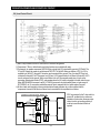
OPERATION PRINCIPLES BY PARTS OF CIRCUIT
5-7) DAMPER CIRCUIT
1) The temperature of R-room is controlled by opening and closing of damper with stepping motor, supplying &
blocking cold air.
2) TA7774P (IC07) operates the damper. TA7774P is the driver IC only for step motor. If the regular signal is
provided to TA7774P from Micom, send combined signal to Quad-Polar step motor to rotate on certain
direction. This makes clockwise or counter clockwise rotation to make the damper open or close.
3) Since the damper always touches the cold air, DC 12V/1W heater is installed, always on to prevent the
malfunction from moisture and is controlled on conditions. (Operation conditions can be changed). Micon #15
pin connected to IC4 controls the damper heater like category 3.
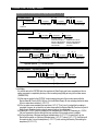
5-8) DISPLAY Circuit
1) KEY SCAN
When Grid #6 is output, this signal goes through PCB resistance 10 ㏀ and provided to power frequency.
When the switch is pressed, R502(6.8 ㏀) and R501 (12 ㏀) decrease the signal and less than 5.1V peak to
peak signal is provided to MICOM, the MICOM recognizes the grid #6 is provided, and change the function
corresponding to switch key. [Refer the circuit diagram below]
21
OPERATION PRINCIPLES BY PARTS OF CIRCUIT
2) DISPLAY OPERATION
Like the signal diagram below, Micom sends “ high ” signal through MICOM 6 terminals of NO #1→ 2 → 3 → 4
→ 5 → 6 for 2ms every 12ms. This signal goes to output terminal via input terminal of IC5 (KID65783AP or
TD62783AP). Output wave always goes through LED input terminal with DC11~12V on every period. At this
time, if SINK signal comes out at IC4, DC11~ 12V is applied to LED input terminal and output terminal sinks to
OV which turn on LED for 2ms For example, to turn on "Power Fre." LED, IC4 #16 pin sinks to 0V when IC5
#16 becomes DC 11~12V making "Power Fre" LED turn on.
� GRID WAVE PATTERN
22
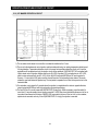
OPERATION PRINCIPLES BY PARTS OF CIRCUIT
5-9) Load Control Circuit
1) Main PCB processes most of the load control for electronic refrigerators.
2) Compressor, F-Room, defrost heater, and other functions are controlled with relay.
3) For example, to operate compressor, MICOM 29 pin outputs high (5V) signal which goes into IC3 Pin #4. The
IC3 pin NO 4 plays the same role as the base of NPN TR. The pin #14 works as collector of TR. So, if 5V is
supplied to pin #4 of IC3, the pin #15 turned on and connected to the ground. Then, the relay RY75 and coil
connected to the pin #15 of IC3 becomes low (OV) and +12V (opposite side of coil) flows to the pin #15 of IC3
via coil and goes into the ground. While current flows to the coil, the magnetic power arise, it turns on the
secondary contact point inside of RY75, and operates when the AC power is supplied to the both side of comp.
When MICOM #29 Pin becomes Low(0V), IC3 #4 Pin becomes Low which makes Power cut and current of
RY75 RELAY cut. So, secondary contact becomes off due to magnetic field cut, which makes Comp off.
4) All other loads work basically on same principle, defrost heater operates only on the condition that the
compressor is turned off like the circuit above, and connected like the equivalent circuit below.
* Q710 is connected to the F door switch to
prevent PL accident due to continuous
operation of motor when the auger motor
control circuit is not working properly. It
must be turned off when the door is
opened.
23
OPERATION PRINCIPLES BY PARTS OF CIRCUIT
5-10) ICE MAKER OPERATION CIRCUIT
1) The ice maker circuit above is to control the ice maker kit installed on the F room.
2) This circuit is the hardware to control ejection and horizontal positioning, ice making temperature detection and
full icing detection. Temperature detection circuit is the same as temperature detection circuit on 4-6 and the
explanation will be skipped and only the ejection circuit will be explained. If MICOM PORT #7 is outputted with
High to rotate motor in ejection direction and the pin #2 of IC5 is inputted, 12V is outputted on pin #17 of IC5,
goes to motor and supplied to pin #11 of IC4. As pin #8 of IC4 and eject MICOM port #7 are connected in
common, 11 output port of IC4 gets on and the current flows into Ground making motor rotates. This motor
rotates the gear and rotates the ejection tray. The tray twists to separate the ice from the tray and return to the
horizontal state.
3) For restoration, motor stops for 2 seconds when the ejection is completed and to rotate in opposite direction,
output horizontal MICOM port with high and perform horizontal positioning.
4) The test S/W is off in normal cases and MICOM PORT 63 stays high. When necessary, press the switch for
more than 1.5 seconds making forced ejection executed. Full S/W has a lever that detects the amount of ice on
ice-maker kit and based on the status of MICRO S/W connected to the lever, if the ice is full on the container,
ejection is not executed, and only if it is off (MICOM PORT 61 is high), the ejection is executed.
24
OPERATION PRINCIPLES BY PARTS OF CIRCUIT
5-11) OPTION Circuit
●
This circuit operates with the initial power on, uses DIODE (1N4148) or JUMPER WIRE.
To modify option circuit, Power must be turned off before modification and turned on after the modification.
Refer to the table below, the default factory values are highly recommended unless exceptional cases.
OP11, OP12
OP11
OP12
MODEL
FUNTION
○
○
RS2*11
No Cruch, 3 Step, Light
○
●
RS2*21
Cruch, 3 Step, Light
●
○
RS2*31
Cruch, 5 Step, P/F, L/T Lock, Filter, Indicator
* ● Jumper USE OP2 < Water Fill Time Control Option >
D601
D602
Fill Time
●
●
5 Sec
●
○
6 Sec
○
●
7 Sec
○
○
10 Sec
* ● Diode(1N4148) USE
25
Remark
Flow Sensor Not USE
Appendix Ⅰ(Reference for circuit diagnostics)
Ref.1) Measure Load Terminals
� Turn off Power, disassemble Housing connected to MAIN PCB CN70,71,72 and measure followings
LOAD
TERMINALS PCB CASE VALUE
1) DEFROST HEATER
2) ICE PIPE HEATER
CN71 ⑪ & ③
DISPENSER HEATER
CN72 ① & ③
WATER VALVE
ICE MAKER
WATER VALVE
DISPENSER
AUGER MOTOR
CUBE SOLENOID
CN70 ⑤ &
CN71 ③
CN70 ⑦ &
CN71 ③
CN70 ① &
CN71 ③
CN70 ③ &
CN71 ③
COMP. FAN MOTOR
CN71 ⑦ & ③
F FANMOTOR
CN71 ① & ③
0Ϊ
∞Ϊ
0Ϊ
∞Ϊ
0Ϊ
∞Ϊ
0Ϊ
∞Ϊ
0Ϊ
∞Ϊ
0Ϊ
∞Ϊ
0Ϊ
∞Ϊ
0Ϊ
∞Ϊ
DEFECTS
THERMAL FUSE, HEATER, WIRE SHORT THERMAL
BIMETAL, HEATER, WIRE CUT
HEATER, WIRE SHORT
HEATER, WIRE CUT OR HOUSING SLIPPED AWAY
COIL, WIRE SHORT
COIL, WIRE CUT
COIL, WIRE SHORT
COIL, WIRE CUT
COIL, WIRE SHORT
COIL, WIRE CUT
COIL, WIRE SHORT
COIL, WIRE CUT
MOTOR, WIRE SHORT MOTOR, WIRE CUT OR
HOUSING SLIPPED AWAY
MOTOR, WIRE SHORT
MOTOR, WIRE CUT OR HOUSING SLIPPED AWAY
39
OTHERS
Appendix Ⅰ(Reference for circuit diagnostics)
� Turn on Power and check status of Relay & Driving Circuit by checking followings according to load operation.
LOAD
DEFROST / COMP OFF
RELAY
RY76 /RY75
TERMINALS
VALUE
WHEN IT IS DIFFERENT FROM MEASURED VALUE
SUPPLY
CN71⑪�⑨ VOLTAGE(SV) RY76 CONTACT SHORT,FAULTY DRIVING CIRCUIT
RY75
CN71⑬�⑨
SV
RY76 /RY75
CN71⑪�⑨
SV
RY75
CN71⑬�⑨
0V
RY76 /RY75
CN71⑪�⑨
0V
F FAN ON
C FAN ON
RY75
RY73 /RY74
RY74
RY73 /RY74
RY74
RY79
RY77
CN71⑬�⑨
CN71⑨�CN70③
CN71⑨�CN70①
CN71⑨�CN70③
CN71⑨�CN70①
CN71①�⑨
CN71⑦�⑨
SV
SV
SV
0V
0V
0V
0V
RY75 NO CONTACT SHORT,FAULTY DRIVING CIRCUIT
FAULTY RY75 /
RY76 NO CONTACT SHORT,FAULTY DRIVING CIRCUIT
RY75 NO CONTACT OPEN, FAULTY DRIVING CIRCUIT
FAULTY RY76 /
RY75 NC CONTACT OPEN, FAULTY DRIVING CIRCUIT
RY75 NO CONTACT SHORT,FAULTY DRIVING CIRCUIT
RY73 &RY74 NO CONTACT SHORT,FAULTY DRIVING CIRCUIT
RY74 NO CONTACT SHORT,FAULTY DRIVING CIRCUIT
RY73 OR RY74 NO CONTACT OPEN, FAULTY DRIVING CIRCUIT
RY74 NO CONTACT OPEN, FAULTY DRIVING CIRCUIT
RY79 NO CONTACT OPEN, FAULTY DRIVING CIRCUIT
RY77 NO CONTACT OPEN, FAULTY DRIVING CIRCUIT
WATER VALVE
DISPENSER OPERATING
RY71
CN71⑨�CN70⑦
0V
RY71 NO CONTACT OPEN, FAULTY DRIVING CIRCUIT
WATER VALVE ICE
MAKER OPERATING
RY72
CN71⑨�CN70⑤
0V
RY72 NO CONTACT OPEN, FAULTY DRIVING CIRCUIT
COMP ON
DEFROST
CUBE & AUGER
MOTOR OFF
CUBE & AUGER
MOTOR OPERATING
Ref.2) Check SENSOR
� Check after disassembling connected to MAIN PCB CN30 &CN32
� Because it is NTC TYPE Sensor, risistance decreases as temp increases
1. Measure resistance between CN30 ⑧ and ⑨ for R-Sensor.
2. Measure resistance between CN30 ⑤ and ④ for F-Sensor.
3. Measure resistance between CN30 ⑥ and ④ for DEF-Sensor.
4. Measure resistance between CN30 ① and ④ for Ambient-Sensor.
5. Compare the above values with current temps of Sensoer locations and Part Spec in Manual and evalute
them.
40
Appendix Ⅰ(Reference for circuit diagnostics)
Ref. 3) SERVICE PARTS LIST FOR CIRCUIT
NO
1
2
ITEM
PBAMAIN
PBA PANEL
3 PBA-LAMP ASSY
4
TRANS DC
SPEC
CODE NO
AD ELECTRONIC RS2*11
DA41-00219A
AD ELECTRONIC RS2*21
DA41-00219B
AD ELECTRONIC RS2*3*
DA41-00219C
RS2*11
DA41-00218A
RS2*21
DA41-00218B
RS2*31
DA41-00235A
RS2*30
DA41-00235B
DISPENSER LAMP
DA41-00217A
115V/60Hz
DA26-00022A
220V/50,60Hz
DA26-00022B
OTHERS
DEF SENSOR
5
SENSOR
DA32-00006D
F SENSOR
R SENSOR
DA32-00006B
AMBIENT SENSOR
PBA PANEL IN
※ The second part DA41-xxxxx? of CODE for MAIN PCB ASS’Y PART can be changed according to
MICOM or Option change, so check it when asking for parts.
41
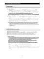
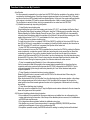
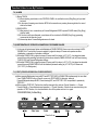
1. INTRODUCTION
●
A newly developed SAMSUNG side by side refrigerator in 2004 has the following
characteristics.
1) Twin X AirFlow
∙Cool air circulates through side vents on every
shelf level. This provides even distribution of
cooling inside cabinets to keep your food fresh
longer.
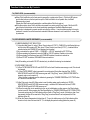
2) Xtra SpaceTM
∙Vertical room next to the ice maker in the freezer
provides space for pizza etc.
3) Door Alarm
∙Beep sound reminds you the door is open.
4) Vegetable Crisper
∙Optimized humidity control keeps vegetables &
fruits fresh.
4
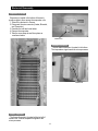
2. INSTALLATION
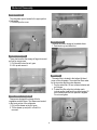
1) To protect refrigerator in movement
Use padded hand truck as shown. If entrance width is
less than 39〃, remove doors prior to installation and
reattach doors according to procedure below.
2) Remove all protective tape and pad in refrigerators.
Connect water lines and power cord. Adjust the
clearance between the doors.
3) Set the temperature control to the temperature and
wait for an hour.
The refrigerator should get slightly chilled and the motor
runs smoothly.
4) Once the refrigerator temperature is sufficiently low
You can store food in the refrigerator. After starting the
refrigerator, it takes a few hours to reach the appropriate
temperature.
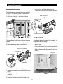
●
Removing Doors(Freezer)
●
Open the freezer and refrigerator doors, and
then take off the front leg cover assembly by
unlocking the hook(upper side:3EA, lower side
:3EA) of the front leg.
Attaching Doors
-Freezer : Attach the freezer door by inserting
the hose in the lower side of the door into the hole
in the lower hinge and pulling the hose down.
-Refrigerator : Insert the lower hinge in the
bracket lower hinge. Attach the door to the
cabinet.
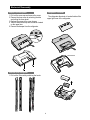
With the door closed, remove the upper hinge
cover using a screwdriver, and then disconnect
the wires. Remove hinge screws and ground
screw counter-clockwise, and take off the upper
hinge. Take care removing the door to ensure that
it does not fall on you.
Remove the door from the lower hinge by
carefully lifting the door so as not to damage the
water tube.
Insert the upper hinge shaft into the hole. After
leveling between the upper hinge hole and the
hole of the cabinet. Reattach hinge screws and
screw in the clockwise direction. Connect the
wires. Put the front part of the upper hinge cover
on the front part of the upper hinge(➀) and
reattach from the front part of the upper hinge
cover first(➁).
5
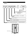
3. Nomenclature
2004 Models
R
S
26
30 SW
/
XAA
Buyer Code:
XAA, XAC, CUR
COLOR ; WW-WHITE(PCM)
SH-STAINLESS PLATINUM
SW-SNOW WHITE
OPTION ; 30-BEST BUY 11,21,31 ; SAMSUNG
Capacity ; 25,26 cu. ft
Family ; S - SIDE BY SIDE (SBS)
Product ; R-SAMSUNG REFRIGERATOR
Label Location
6
B-OEM REFRIGERATOR
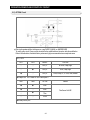
4. Specifications
ELECTRICAL SPECIFICATIONS
Freezer
Refrigerator
Defrost Control
From 6 to 11 hrs
Defrost Thermistor(502AT)
59℉(off)
Electrical Rating
AC115V 60Hz 11.6 Amps
Maximum Current Leakage
0.25 mA
Maximum Ground Path Resistance 0.1Ohm
Energy Consumption
kWh/mo.
Bimetal
104℉(on)/140℉(off)
NO LOAD PERFORMANCE
Ambient Temperature
Refrigerator,℉
Freezer,℉
Run Time,%
70℉
34�46
-11�7
�40
90℉
34�46
-11�7
�60
REFRIGERATION SYSTEM
Refrigerant Charge (R134a)
6.17 oz
Compressor(MK183C-L2U)
1032 Btu/hr
Compressor oil
Freol α-15
",130"
"
0.033"
Capillary tube(Dia, Length)
Dryer
Molecular Sieve XH-9
MODELS
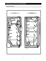
RS2530, RS2630
Electric box
Dryer
Compressor
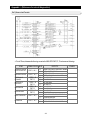
REPLACEMENT PARTS
PBA MAIN(RS2*11)∙∙∙∙∙∙∙∙∙∙DA41-00216A
PBA MAIN(RS2*21)∙∙∙∙∙∙∙∙∙∙DA41-00217B
PBA MAIN(RS2*30) ∙∙∙∙∙∙∙∙∙DA41-00218C
PBA MAIN(RS2*31) ∙∙∙∙∙∙∙∙∙DA41-00219D
PBA PANEL(RS2*11)∙∙∙∙∙∙∙∙∙DA41-00218A
PBA PANEL(RS2*21)∙∙∙∙∙∙∙∙∙DA41-00218B
PBA PANEL(RS2*30)∙∙∙∙∙∙∙∙∙DA41-00235A
PBA PANEL(RS2*31)∙∙∙∙∙∙∙∙∙DA41-00235B
TRANS DC(115V/60Hz) ∙∙∙∙∙∙∙DA26-00022B
TRANS DC(220V/50,60Hz) ∙∙∙∙∙DA26-00022C
TRANS DC(127V/60Hz) ∙∙∙∙∙∙∙DA26-00022D
SENSOR(DEF SENSOR) ∙∙∙∙∙∙DA32-00006D
SENSOR(F SENSOR) ∙∙∙∙∙∙∙∙DA32-00006D
SENSOR(R SENSOR) ∙∙∙∙∙∙∙∙DA32-00006B
SENSOR(ICE MAKER SENSOR)∙DA32-10108B
RELAY ∙∙∙∙∙∙∙∙∙∙∙∙∙∙∙∙∙∙DA35-10013Q
OVERLOADED REALY ∙∙∙∙∙∙∙DA35-10013D
RUN CAPACITOR(12 ßfi) ∙∙∙∙∙∙∙2501-001045
FAN MOTOR(FREEZER) ∙∙∙∙∙∙DA31-00003W
FAN MOTOR(UNIT) ∙∙∙∙∙∙∙∙∙∙DA31-00103A
Sub-Condenser
INSTALLATION
Clearance must be provided for air circulation
"
AT TOP
1"
"
AT SIDES
1/8"
"
AT REAR
1"
7
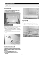
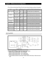
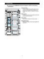
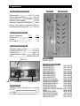
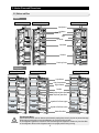
5. Interior Views and Dimensions
5-1) Shelves and Bins
Freezer
RS2511** / RS2611**
RS2521** / RS2621**
RS2531** / RS2631**
Xtra SpaceTM
Ice Maker
Door Bin
Light
Ice Chute
Wire Shelf
Drawers
Front Leg Cover
Refrigerator
RS2511** / RS2611**
RS2521** / RS2621**
RS2531** / RS2631**
Light Switch
Dairy Compartment
Egg Container
Deli Bin
Spill-proof glass Shelf
Tempered glass Shelf
Vegetable & Fruit Drawer (upper)
Vegetable & Fruit Drawer (lower)
Gallon Door Bins
CAUTION
Preparing to Move
Secure all loose items such as shelves and drawers by taping them securely in place to prevent damage.
When using a hand truck to move the refrigerator, do not rest the front or back
of the refrigerator against the hand truck.This could damage the refrigerator. Handle only from the sides
of the refrigerator. Be sure the refrigerator stays in an upright position during moving.
8
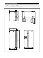
Interior Views and Dimensions
5-2) Dimensions of Refrigerator(RS26**) (Inches)
3.4
51.2
46.2
35.6
3.4
67.9
64.5
32.2
4.4
32.1
9
21.4
16.4
15.2
35.8
20.1
29.5
Interior Views and Dimensions
5-3) Dimensions of Refrigerator(RS25**) (Inches)
29.5
50.9
45.9
34.9
3
69.7
64.5
31.9
4.4
32.1
10
21.4
16.4
15.2
35.8
20.1
2.0
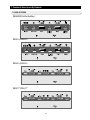
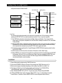
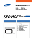
6. Refrigeration Cycle and Cool Air Circulation Route
6-1) Refrigerant Route in Refrigeration cycle
Compressor →Condenser → Hot Pipe → Dryer → Capillary Tube → Evaporator → Suction Pipe →
Compressor
Accumulator
Evaporator
Dryer
Hot Pipe
Suction Pipe
Condenser
Capillary Tube
Muffler
Compressor
Hot Pipe
11
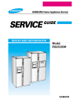
Refrigeration Cycle and Cool Air Circulation Route
6-2) Cool Air Circulation
Refrigerator
Freezer
12
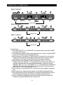
7. Function & How- to-use By Products
7-1) DISPLAY DESIGN
RS2630SW/XAA (for Best Buy)
RS2531**/RS2631**
RS2521**/RS2621**
RS2511**/RS2611**
13
7. Function & How- to-use By Products
7-2) TEMP CONTROL
1) Freezer Temp Setting
1-1) With the initial power on, Freezer will be set at MID (-4°F/-20°C) and Refrigerator will be set at MID
(37°F/3°C) automatically. At this time, the number of LEDs (1 ~ 5) lighting up on the display panel means
intensity (MIN ~ MAX) of room control temperature (6.8 ~ -13°F/-14 ~ -25 °C) and as the intensity gets
increased, the number of LEDs increases and the set temperature become lowered.
1-2) Freezer Temp can be set from (6.8°F/-14°C)(MIN) to (-13°F/-25°C)(MAX) with Freezer temp setting button.
2) Refrigerator Temp Setting
2-1) Refrigerator Temp can be set from (44.6°F/7°C)(MIN) to (33.8°F/1°C)(MAX) with Refrigerator temp setting
button.
2-2) Refrigerator set temp varies slightly from actual temperature according to the user’s way of storing food
and peripheral temp. (If food is stored too close to Refrigerator Temp Sensor, it can block air circulation
resulting in weak or over cooling. So, be careful not to block it.)
Note) When power is out due to an instant power failure or the problems in an electric circuit and restored
again, the ref checks Refrigerator Temp. At this time, When Freezer Temp is lower than (41°F/5°C) ,
Refrigerator considers it as an instant power failure and restores the previous temp and functions stored
in EEPROMforuse.
7-3) POWER FREEZING (on some models)
● It is selected with Power Freeze Button.
● Each time you press Power Freeze Button, it repeats SELECT
↔ CANCEL (Relevant ICON ON/OFF).
● When Power Freeze is selected, the temp settings of Refrigerator/Freezer does not change.
● When Power Freeze is selected, it is possible to change the temp settings of Refrigerator/Freezer.
1) POWER FREEZING
1-1) When Power Freeze is selected by pressing Power Freeze Button, ICON gets on immediately but Power
Freeze starts its operation in 10 sec. However, when Power Freeze Button is reselected during Power
Freeze, ICON gets off and operation ends with the selection of Power Freezing.
1-2) When Power Freeze is selected, Comp & Freezer-Fan operates continuously for 2hr. and 30min.
1-3) During Power Freeze, Refrigerator continues its previous operation.
1-4) After turning off of Power Freeze, Power Freeze lamp goes off automatically and Freezer operates
according to the set temp.
1-5) When it becomes conditions for Defrost during Power Freeze, Defrost gets delayed and it starts operating
upon completion of Power Freeze.
When Power Freeze is selected during Defrost, Power Freeze ICON lights up immediately. But, Comp and
Freezer-Fan gets on upon completion of Defrost. (But, the initial 4hr. Defrost comes before Power Freeze)
14
Function & How- to-use By Products
7-4) CHILD LOCK (on some models)
When Child Lock Button on the front panel is pressed for a certain period (3sec.), Child Lock LED gets on
and all other buttons on the front panel except for Child Lock Button do not operate. Also, Ice/Water
Dispensers do not work.
(Display & all Ref functions will maintain the conditions before Child Lock gets on)
● In the above status, when Child Lock Button is pressed for a certain period (3sec.) again, Child Lock LED
gets off and all other buttons on the frontal panel start operating and Ice/Water Dispensers work.
● This function is developed to prevent random controlling by children. It can be used according to the user’s
need and it needs to be well informed and reminded in advance because it could make Non----sense Calls
by customers.
●
7-5) ICE DISPENSER & WATER DISPENSER (on some models)
1) CUBE/CRUSHED/ICE OFF SELECTION
1-1) Upon the initial Power On, when F-Room Temp is above (41°F/5°C), CUBE LED on the Display lights up
and the other LEDs remains OFF. But, when F-Room Temp is lower than (41°F/5°C), it restores the ice
selection before the POWER OFF and displays it on the panel.
1-2) It is selected in the order of CUBE → CRUSHED → ICE OFF repeatedly by ICE TYPE key.
1-3) When operating Ice Dispenser Lever with CUBE or ICE OFF selected, it sends out ice cubes.
1-4) When pressing Ice Dispenser Lever with CRUSHED selected, it sends out crushed ice.
1-5) When ICE OFF is selected, ICE-MAKER does not make ice.
Note) When taking out ice with ICE OFF selected, only ice lefted in the storing box is extracted.
2) FILTER RESET OR LIGHT
2-1) When FILTER INDICATOR LED and LIGHT LED on the front Panel becomes orange or red, Filter should
be changed.
2-2) - When FILTER RESET button is pressed for a certain period (3sec) after changing Filter, FILTER
INDICATOR LED and LIGHT LED becomes green with “ Ding Dong ” sound. (When FILTER RESET is
pressed, water count is reset to 0)
- When the filter is replaced,reset the indicator by pressing the "POWER FREEZE"and "ICE TYPE"button
for 3 second at the same time.
2-3) After Filter reset, when 450 Gallon water is used (including water used in making ice), FILTER
INDICATOR LED and LIGHT LED becomes orange , and when 500 Gallon water is used, FILTER
INDICATOR LED and LIGHT LED becomes red.
2-4) When the water filter is not needed due to the use of purified water or other reasons, the Filter Indicator
can be turned off. When pressing the Filter Reset Button for (“POWER FREEZE and ICE TYPE BUTTON)
5 seconds continuously, the Filter Indicator will be off with a "Ding Dong" sound. (At this time, when 3 sec
has passed, the filter will be reset with a "Ding Dong" sound and when 5 sec has passed, the Filter
Indicator will be off.)
2-5) When the Freezer temperature is higher than 41 °F upon the initial power on, the Filter Indicator will be
turned on. And, when it is lower than 41 °F, it will display the previous setting (before the power off).
15
Function & How- to-use By Products
7-6) FAN MOTOR DELAY (COMPRESSOR ROOM)
●
Among the functions depending on Peripheral Temp, Comp Cooling Fan (Comp Room Fan) is controlled
according to Peripheral Temp as follows.
Therefore, make sure to check the contents to refer to during A/S because Cooling Fan can operate or not
according to conditions during Comp operation.
Comp Room
DELAY
Range of Ambient Temp
Load operation state
Above (64.4°F/18°C)
With COMP.ON, Comp Room Fan will be
on immediately
Between (55.4°F/13°C)
and (62.6°F/17°C)
After 5 min. from COMP.ON, Comp
Room Fan will be on
Below (53.6°F/12°C)
Regardless of COMP., Comp Room
Fan will be off
7-7) ICE MAKER
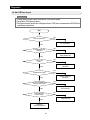
1) Initialization (Restoration to the initial horizontal status)
When the Ice Maker is initialized by Power On or the Ice Error Mode, the Ice Tray gets leveled again by
rotating the Eject Motor regardless of the horizontal state of the Ice Tray.
1-1) Conditions for Initialization
- After pending time (5sec.) for activation of each MICOM port with the initial Power On or the Power
On after Power Failure.
- When an error occurs due to full icing or the restraint of the Eject Motor, it starts initialization in 24 hours
upon full icing and in an hour upon the counter-rotation error of the Eject Motor.
1-2) Movement for Initialization
- Satisfy the initial horizontal status by counter-rotating the Eject Motor.
- When the voltage of the Motor Voltage Sensor becomes above 0.55V during counter-rotation of the
Eject Motor, the counter-rotation stops.
- To protect the Gear by releasing its stress a second later after the above directions, rotate the Eject
Motor clockwise for 2ms.
- When it is not detected that the Motor Voltage Sensor becomes more than 0.55V for a minute after
the counter-rotation, it is considered as an error and initialization gets started again in an hour.
- It stands by for the initial Ejection for a cycle (2 hours) after completion of initializing movement by Power
On and it stands by for normal Ejection after completion of initializing movement by error.
- After the Ejection Stand-by time has passed, check the temp of the Ice Tray and if the temp reaches
to the Ejection temp, it carries out the Ejection.
1-3) Initializing Movement Timing Chart
Voltage of Ice
Ejection Motor
0.55V ↑
0.5V ↓
Ice Ejection Motor
(Counter clockwise)
ON
OFF
Ice Ejection Motor
(Counter clockwise)
ON
OFF
Initialization starts
16
Function & How- to-use By Products
2) Water Supply
It is the movement to supply water on the ICE-TRAY by using the SOLENOID VALVE after the completion
of the ejection (Ejection after the completion of the normal ice making or that by the test movement)
Considering cases with low hydraulic pressure, when it is recognized as No Water Supply, the Water Supply
will be attempted for 4 times.
2-1) Specifications for water supply
- After the completion of the normal ejection and the opening of the water supply valve, water is supplied for
the previously set OPTION time (Set by the DIODE in PCB and normally for 5 sec) and the water supply
valve gets off.
- Water is supplied regardless of the F/R-DOOR OPEN
- While supplying water, the ICE TEST S/W doesn’t work.
- In one min. and 30 sec. after the completion of water supply, Water Supply/ No Water Supply will be
judged.
- Under the condition of additional water supply due to No Water Supply, the additional water supplying time
is 1.5 sec, 1 sec, and 2 sec.
- When judging water supply after the trial of water supply within the number of previous water supply,
complete water supply. In this case, the Ejection Stand-By Time is 55(60) min.
- To prevent the additional water supply by the judgment of No Water Supply due to the ice cube on the tray
cube which the ice maker sensor of the ICE-TRAY is, quit the water supplying movement for one time
when it is judged as No Water Supply after trying to supply water as many as the number of the previous
water supplying. After POWER ON, the number of the previous water supplying will be considered as
once for the first water supplying and when No Water Supply is judged after the initial water supplying, quit
the water supply movement. If the number of the previous water supply is three times, supply water for 3
times, and when judged as No Water Supply, quit the water supplying movement. In this case, the
Ejection Stand-By Time is 70~100 min.
- When judged as No Water Supply in the previous water supply, supply water for 5 sec, 1.5sec, 1sec,and 2
sec for 4 times.
- According to conditions, the Ejection Stand-by Time is as follows.
Number of
water supply
Detection of Water Supply
Detection of No Water Supply
Lower than (62.6°F/17°C) Higher than (64.4°F/18°C) Lower than (62.6°F/17°C) Higher than (64.4°F/18°C)
1
60 (55+5) min
55 min
100 min
90 min
2~4
55 min
55 min
70 min
70 min
2-2) Judgment of Water Supply by the ICE-TRAY Temp sensor
- In one and a half min after the completion of the water supply, judge either the Water Supply or the No
Water Supply by comparing the temp change of the ice maker sensor on the ICE TRAY.
- In the case that the temp of the ICE-TRAY ice maker sensor in one and a half min. after the completion of
the water supply is 2 degrees (5 COUNT) higher than that during the water supply movement, it is judged
as the Water Supply and when the temp increases or decreases less than 2 degrees, it is considered as
the No Water Supply.
2-3) Specifications of water supply movement upon pressing the Ice Test S/W
- Supply water for once regardless of the previous water supply.
- The Ejection Stand-by Time after the completion of water supply is the same as that after the completion
of the previous water supply movement regardless of the Water Supply/ No Water Supply recognition.
- Do not change the number of the previous Water Supply. That is, if the number of Water Supply before
pressing the ICE TEST S/W is 3 times, that of the previous Water supply after the completion of the Water
Supply by pressing the ICE TEST S/W is also 3 times.
17
Function & How- to-use By Products
Assumption of the ambient temp of higher than 64.4 °F/ 18 °C
Low water pressure
5s
5s 1.5s
Initial 2hr standby
5s
1.5s 1s
90+(5)min
70+(5)min
70+(5)min
No Water Supply
No Water Supply
No Water Supply
Power On
High water pressure
5s
5s
5s
55+(5)min
90+(5)min
Water Supply
55+(5)min
No Water Supply
Water Supply
when the Ice cube on When the ice cube on
the tray cube which the the tray cube which the
sensor is attached is
sensor is attached is
not removed.
removed.
High water pressure → Low water pressure
5s
5s
55+(5)min
Water Supply
High water pressure
5s 1.5s
90+(5)min
No Water Supply
5s 1.5s 1s
70+(5)min
55+(5)min
No Water Supply
Water Supply
Low water pressure
Low water pressure → High water pressure
5s 1.5s 1s
2s
5s
55+(5)min
Water Supply
Low water pressure
5s
55+(5)min
Water Supply
55+(5)min
Water Supply
High water pressure
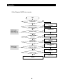
3) Ice Making
It is until the water in the ICE-TRAY after the completion of Water Supply gets frozen completely and the ice
making movement is completed by the temp of the ice making temp pickup part using the ice maker sensor
(THERMISTOR).
3-1) After water is supplied to the ICE-TRAY, check the temp pickup part of the ice maker sensor after the
Ejection Stand-By Time for 55(55~100) min. (For the No Water Supply, 90 min) and judge whether the temp
of the ice maker sensor is below (1.4°F/-17°C).
3-2) If the ice maker sensor maintains the temp below (1.4°F/-17°C) for 5 min. It is judged that ice making is
completed. However, do not check the ice maker sensor within the Ejection Stand-By Time from the point of
Water Supply. (Protection function when the sensor is faulty or the cold air leaks.)
3-3) Stand-by for 1 CYCLE: After the completion of the initialization by POWER ON, it stands by for 1 CYCLE
(2hr.) and operates the Ejection although the temp condition of the ice maker sensor is satisfied.
3-4) As long as the temp of the temp sensing part maintains below (1.4°F/-17°C) for more than 5 min, the
Ejection will be carried out. If the temp fluctuates below (1.4°F/-17°C) above (1.4°F/-17°C), the Ejection will
be carried out after 5 min. at the temp below (1.4°F/-17°C) while counting the Stand-by Time entering the
temp below (12.2°F/-11°C).
18
Function & How- to-use By Products
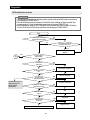
4) Ice Ejection
It is the movement to separate the ice cubes from the ICE-TRAY after the completion of ice making, which is
conducted by the following steps. Check the changes in status and time for the horizontal S/W (if it is used)
and the ice level check S/W in parallel and then operate Ejection. At this point, the regular rotational direction
of the motors is clockwise (CC) and the reverse rotational direction of that is counter clockwise (CCW).
The Ice Ejection is carried out twice, which is to separate all the ice cubes from the ICE-TRAY.
4-1) Detailed movements by step during the Ejection.
- 1st step: Ejection temp checking step
Check whether the temp of the temp sensing part is below (5°F/-15°C) and whether the Ejection StandBy Time after Water Supply has passed. At this point, when the F-Defrost goes into operation during the
Ejection Standby, the Ejection Standby Time will be reset. Then, check that 55(90) min. has passed by
recounting from the beginning after the completion of the Defrost. If the temp of temp sensing part of ice
making become below (1.4°F/-17°C) and maintain it for 5 min, carry on the next step.
- 2nd step: Filled up ice container checking step
To check the ice level of the ice container, CHECK the ON/OFF (Low/High) of the ice level S/W If the ice
level S/W is ON (Low), it means that the ice container is full and the Ejection stands by. And when the ice
level S/W is turned OFF and 40 min. has passed, the Ejection will be carried out.
- 3rd step: ICE TRAY overturning step (clockwise)
It is the movement to turn over the TRAY to separate the ice cubes from the TRAY by rotating the Ejection
motor clockwise for a certain time period. At this point, raise the guide ice to prevent the ice cubes from
contacting the guide ice. Carry out the clockwise rotation for a minute from the start of the clockwise
rotation or until the horizontal S/W is ON (Low) after 5 sec from the beginning of the third step when using
horizontal S/W. If the door of the F-Room is open, stop the clockwise rotation and start the rotation after
the door is closed. During the temporary pause, the clockwise rotation will not be counted.
- 4th step: Ice separating step (Standby for 2 sec. at the maximum twist point )
It is the movement to twist the tray again in the reversed state to separate the ice cubes from the tray
completely and the tray receives torsion because the ICE-TRAY is stopped by the STOPPER. The ice
cubes are separated by this strength and the tray stands by for 2 sec. at the maximum twist point for
complete separation.
- 5th step: Reverting to horizontal level step (counter clockwise)
Rotate the Ejection motor in reverse to revert the ICE-TRAY to the horizontal level. When using the
horizontal S/W, reverse rotation begins.
When the horizontal S/W is ON (Low) after 5 sec from the beginning of the reverse rotation or the voltage
of the voltage sensing part of the motor is above 0.55V, the rotation will be stopped. At this point, the
raised guide ice becomes lowered again and touches on the highest point of the stored ice for checking
the ice level.
- 6th step: Motor initializing step (clockwise)
After a sec. upon the completion of the 5th step, the Ejection motor rotates clockwise for 2ms to release the
stress of the gear as well as to protect it.
4-2) Errors and handling methods during the ejection
- If the conditions of the completion for the reverse rotation are not satisfied in a min. after applying the
counter rotation during the execution of the 5 steps of the detailed ejection movement, it is considered as
an ERROR and stops the motor.
- If it is judged as an abnormal state, facilitate the initialization in an hour.
If the ejection error occurs 3 times consecutively, it is sensed as ERROR (ICE ERROR) and when
selecting the self diagnosis, it turns on the corresponding LED.
- If the ejection operates normally, the ERROR value of the existing ice making function will be deleted.
19
Function & How- to-use By Products
4-3) Ejection Movement TIMING CHART
Max TRAY twist
Initial
horizontal status
Ice Level S/W
ON
OFF
Eject Motor rotates
clockwise
ON
OFF
Eject Motor rotates
counter clockwise
ON
OFF
Ejecting
Standby(2sec)
Restorating to
Completion
horizontal status horizontal status
5) Ice Test
It is necessary for the forced operation for the purpose of the operation test, A/S, and cleaning, and when
pressing the ICE TEST S/W for a certain time period (more than 1.5 sec.), it goes into operation.
5-1) The TEST button will not be selected during the Water Supply or the Ejection. Press it again with the
Water Supply or the Ejection completed to run the Test function. Standby for maximum 5 min. when Water
Supply operates.
5-2) When the TEST button is selected, the ejection will be carried out by running the eject motor regardless of
the elapsed time (55 min.) after the Water Supply and the temp of the ice making. And after this, the tray
will be reverted to the horizontal level and the ICE TRAY will be supplied with water.
5-3) It operates normally regardless of the Freezer/Refrigerator DOOR OPEN (No temporary pause functions
by the DOOR OPEN)
5-4) Other functions are the same as the movements of the Ejection and the Water Supply.
5-5) When ERROR occurs more than 3 times with the normal function and the ice making stops, the ICE TEST
shall operate. At this point, if the normal Ejection and Water Supply are operated by the TEST S/W, there
would be “Ding Dong” sound for once before the Water Supply and the third ERROR MODE will be
cancelled executing the normal ice making.
7-8) DEFROST
1) Freezer Defrost shall be determined by COMP ON total hour.
2) On the initial POWER ON, Defrost in Freezer will be operated after COMP ON total hour of 4 hr.
3) Defrost cycle changes automatically depending on the conditions from MIN 6 hr. to MAX 11 hr.
4) The judgment of defrost cycle shall be determined by peripheral temp, No. of DOOR OPEN in
Freezer/Refrigerator, and the time for DOOR OPEN in Freezer/Refrigerator.
5) Point of Defrost HEATER OFF is (59 °F/15 °C) by the temp value of Freezer Defrost SENSOR.
●
If F Defrost HEATER doesn’t reach to the point of Defrost OFF in 7 min., turn off forcibly and complete
Freezer-Defrost. ( Prevention of inferior HEATER OPEN or inferior Refrigerator Defrost Sensor )
20
Function & How- to-use By Products
7-9) ALARM
1) Button TOUCH
1-1) When selecting each button in the CONTROL PANEL, the verification sound (Ding Dong) of input shall
be heard.
1-2) In the case of pressing more than two KEYS at the same time or pressing the wrong button, the sound
shall not be heard.
2) DOOR-OPEN
2-1) After passing 2 min. consecutively as Freezer/Refrigerator DOOR opened, SOUND alarm (Ding Dong)
shall be heard.
2-2) If the door is still open afterward, sound alarm will be circulated to SOUND (Ding Dong) generating
movement at the interval of a min.
2-3) Alarm stops when Freezer/Refrigerators are all closed.
7-10) RESTORATION OF OPERATION CONDITIONS FOR POWER FAILURE
1) In the case of instant power failure and initialization of PANEL DISPLAY, these can make customer’s NONSENSE CALL. To avoid this, if power is applied, it judges the temp of Freezer and operates as either
initialization or restoration of operation conditions.
2) With initial POWER ON, it judges the temp of Freezer and if it is below (+41°F/+5°C), it is judged as instant
power failure while operating and restoring the functions related to PANEL DISPLAY such as Power freezing,
CHILD LOCK and Freezer/Refrigerator settings.
3) With initial POWER ON, it judges the temp of Freezer and if it is above (+41°F/+5°C), it is judged as extended
power failure and PANEL DISPLAY will be initialized (Automatic setting at (-4°F/-20°C) for Freezer and
(37.4°F/3°C) for Refrigerator).
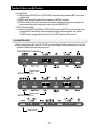
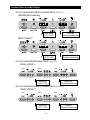
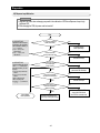
7-11) TEST (FORCED OPERATION / FORCED DEFROST)
When pressing Refrigerator temp set KEY and ICE TYPE KEY in PANEL PCB simultaneously for more than
8 sec. PANEL DISPLAY will go off and it moves onto TEST MODE. At this point, although
Freezer/Refrigerator temp set KEY, Power freezing KEY, and ICE TYPE KEY are pressed, it operates by
TEST KEY.
● When pressing TEST KEY, Test function shall be changed in the order as Forced Operation ---> Forced
Freezer Defrost---> Cancellation(normal operation)---> Forced Operation. If functions are canceled during the
operation of TEST function, it is most desirable to turn off the power and turn it on again.
●
RS2630SW/XAA (for Best Buy)
Press for 8 sec
21
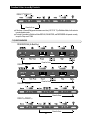
Function & How- to-use By Products
RS2531**/RS2631**
Press for 8 sec
RS2521**/RS2621**
Press for 8 sec
RS2511**/RS2611**
Press for 8 sec
1) Forced Operation
1-1) When pressing TEST KEY once in TEST MODE, Forced Operation shall be selected and with BEEP
sound, alarm will be operated.
1-2) If Forced Operation is selected, COMP. operates instantly without 5 min. delay in any Operation MODE.
At this point, if it is in Defrost, Defrost will be stopped instantly.
1-3) With the selection of Forced Operation, COMP. and Freezer FAN operate for 24 hr. continuously and
Refrigerator shall be regulated by set temp while Forced Operation continues until the completion of
forced operation or the conversion to other MODE (forced Freezer Defrost) or cancellation.
1-4) With the selection of Forced Operation, Freezer will be selected at “ MAX(-13 °F/ -25 °C) ”and
Refrigerator will be set at “ MID (35.6 °F/ 2 °C) ”automatically. However, although forced defrost or test
cancellation are selected after a minute while selecting forced operation, set temp will not change.
(Maintaining “ MAX (-13 °F/ -25 °C) ” and “ MID(35.6 °F/ 2 °C) ” ) If forced defrost or test cancellation are
selected in a minute while selecting forced operation, set temp will go back to the previous set temp
before “ MAX (-13 °F/ -25 °C) ” and “ MID (35.6 °F/ 2 °C) ” .
1-5) On the completion of Forced Operation (24 hr.), Freezer defrost will operate regardless of the previous
state.
1-6) After the above items, it operates under the conditions of normal defrost by judging case by case.
1-7) If it is cancelled randomly during Forced Operation, (On changing into cancellation Mode), the time for
COMP. ON during forced operation shall be calculated in total and reflected in defrost cycle.
1-8) During Forced Operation, Power freezing doesn’t function and with the selection of function, LED
indication for the selected POWER function will be off after 10 sec.
22
Function & How- to-use By Products
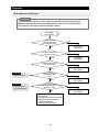
2) Forced Defrost
2-1) When pressing TEST KET twice in TEST MODE, Freezer defrost will operate and BEEP sound alarm
shall be heard.
2-2) BEEP sound alarm shall operate until the completion of HEATING and pause.
2-3) With the selection of forced Freezer defrost, it will operate regardless of the point of normal Heater On
and complete defrost while comparing the temp of the point of HEATER OFF.
3) TEST Cancellation MODE
3-1) When converting DISPLAY PANEL into TEST MODE and pressing TEST button one more time during
Freeaer Defrost, Freezer Defrost will be cancelled and restored to normal operation. Also, if MAIN
POWER is turned on again after being turned off, all the TEST functions will be canceled.
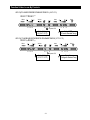
7-12) EXHIBITION MODE
●
When pressing Freezer KEY and ICE TYPE KEY on the front Display PANEL simultaneously for 8 sec. It will
operate as Exhibition Mode with Ding Dong sound.
RS2630SW/XAA (for Best Buy)
Press for 8 sec
RS2531**/RS2631**
Press for 8 sec
RS2521**/RS2621**
Press for 8 sec
23
Function & How- to-use By Products
RS2511**/RS2611**
Press for 8 sec
If the temp of Freezer/Refrigerator increases more than (149 °F/ 65 °C) in Exhibition Mode, it will restore to
normal operation mode.
● Contents of operation in Exhibition Mode DISPLAY, FAN MOTOR, and DISPENSER will operate normally
except for Comp. and C-FAN.
●
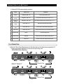
7-13) SELF-DIAGNOSIS
RS2630SW/XAA (for Best Buy)
Press for 8 sec
RS2531**/RS2631**
RS2521**/RS2621**
Press for 8 sec
Press for 8 sec
RS2511**/RS2611**
Press for 8 sec
24
Function & How- to-use By Products
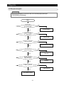
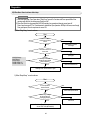
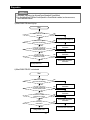
1) Self-diagnosis with initial POWER ON
1-1) With POWER ON, it shall diagnose the status of temp SENSOR in a minute in MICOM internally for itself.
1-2) If inferior sensor is found after self-diagnosis, corresponding DISPLAY LED will be all off at the interval of
0.5 sec. and there will be no sound with LED ON.
1-3) In the state that inferior sensor is found and DISPLAY ICON is off, it only recognizes self-diagnosis KEY
(Press Ice Type KEY + FILTER RESET KEY(LIGHT KEY) for 8 sec.) and normal temp control will be on
hold.
1-4) On self-diagnosis ERROR, if inferior sensor is fixed or if you press ICE TYPE KEY + FILTER RESET
KEY(LIGHT KEY) for 8 sec., it will be canceled automatically.
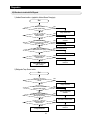
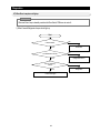
2) Self-diagnosis during normal operation
2-1) When pressing “ ICE TYPE ” and “ FILTER RESET(LIGHT) ” KEYS simultaneously for 6 sec. in normal
operation of the fridge, temp set DISPLAY will be All ON/OFF for 2 sec. at the interval of 0.5 sec. and
when pressing “ ICE TYPE ” and “ FILTER RESET(LIGHT) ” KEYS simultaneously for 8 sec. including
TOGGLE for 2 sec., self-diagnosis will be selected.
2-2) At this point, “ SOUND ”shall be heard and it operates self-diagnosis.
2-3) When self-diagnosis operates, entire LED will be OFF and only relevant LED with malfunction will be ON
/ OFF repeatedly signifying defects. (Refer to the below self-diagnosis CHECK LIST)
2-4) When an ERROR occurs, it will be indicated for 30 sec. and restored to the normal status regardless of
maintenance.
2-5) During self-diagnosis KEY input will not be recognized.
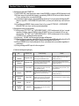
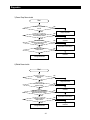
� Details of self-diagnosis lighting by
NO
Item
DISPLAY LED
Trouble Shooting
Remark
01
Refrigerator
SENSOR
Refrigerator "MID"
Indicating a defect when the temp sensing of
Fall out SENSOR HOUSING in Refrigerator
contanct failture, breakage of wire, short-circuit, Refrigerator SENOSR is above (149 °F/65 °C)
and below (-58°F/-50 °C).
inferior Refrigerator SENSOR and others.
02
Peripheral temp
SENSOR
Refrigerator "MIN"
Fall out peripheral temp SENSOR HOUSING ,
contact failure, breakage of wire, short-circuit,
inferior peripheral sensor and others.
03 Freezer SENSOR
04
05
Freezer Defrost
SENSOR
Freezer Defrost
ERROR
Indicating a defect when the temp sensing of
peripheral temp SENOSR is above (149 °F/65 °C)
and below (-58°F/-50 °C).
Freezer "MAX"
Fall out SENSOR HOUSING in Freezer, contact Indicating a defect when the temp sensing of
Freezer SENOSR is above (149 °F/65 °C) and
failure, breakage of wire, short-circuit, inferior
below (-58°F/-50 °C).
Freezer SENSOR and others.
Freezer "MID"
Fall out Deforst -SENSOR HOUSING in the
indicating a defect when the temp sensing of
evaporator of Freezer, contact facilure, breakge
Freezer Defrost SENOSR is above (149 °F/65 °C)
of wire, short-circuit, inferior sensor and
and below (-58°F/-50 °C).
others.
Freezer "MIN"
Fall out Freezer Heater Housing, contact failture,
breakage of wire, short circuit, inferior Freezer
On Freezer Defrost 90 min. automatic completion
Heater, or inferior Defrost temp fuse and etc.
06
I/M Function
ERROR
ICE OFF
Ejection restoration failure more than 3 times.
07
I/M SENSOR
ERROR
Cubed LED
Fall out I/M SENSOR HOUSING, contact
failure, brekage of wire, short-circuit, inferior
I/M-SENSOR and etc.
25
Function & How- to-use By Products
7-14) LOAD STATUS DISPLAY
1) When pressing “ICE TYPE” and “FILTER RESET(LIGHT)” KEYS simultaneously for 6 sec. in normal
operation, the indicators of temp set in Freezer/Refrigerator will all ON/OFF for 2 sec. at the interval of 0.5 sec.
At this point, when pressing Temp Set Key in Refrigerator while canceling “ICE TYPE” and “FILTER
RESET(LIGHT)” KEYS, it operates load status display.
2) Load status display will show the load in operation REAL TIME.
However, it is not related to real status of operation of load and it only shows the directed status of the load
operation command from MICOM.
3) Only corresponding ICON for the load in operation will be ON/OFF repeatedly and turned off.
4) Load status display will continue for 30 sec. and it will restore to the normal state.
RS2630SW/XAA (for Best Buy)
① Press for 6 sec
② Press after ①
RS2531**/RS2631**
① Press for 6 sec
② Press after ①
RS2521**/RS2621**
① Press for 6 sec
② Press after ①
RS2511**/RS2611**
① Press for 6 sec
② Press after ①
26
Function & How- to-use By Products
� Details by LED ON locations indicating load status
NO
ITEMS
DISPLAY LED
PROBLEM
01
Damper
Refrigerator "MIN" (1’st)
LED ON whenDamper is open
02
Condition for
over load
Refrigerator "MID" (3’rd)
LED ON when Ambient temp is over (95°F/35 °C)
03
Condition for
low temp
Refrigerator "MAX" (5’th)
LED ON when ambient temp is lower than (62.6 °F/17 °C)
04
COMP
Freezer "MIN" (1’st)
Relevant LED ON whenCOMP operates
05
Freezer Defrost
Heater
Freezer "MID" (3’rd)
LED ON when Freezer Defrost Heater operates
06
Freezer FAN
Freezer "MAX" (5’th)
Relevant LED ON when Freezer-FAN HIGH operates
07 Exhibition Mode
ICE OFF
LED ON in Display mode
08 Dispenser Heater
CUBE LED
Relevant LED ON when Dispenser Heater gets ON
09 Damper Heater
CRUSH LED
Relevant LED ON when Damper Heater gets ON
7-15) OPTION SETTING
● When the F-Room Temp Setting button and the Filter Reset button or the Lighting button are pressed for 12
seconds continuously,the display will be converted to the option setting mode.
RS2630SW/XAA (for Best Buy)
Press for 12 sec
RS2531**/RS2631**
Press for 12 sec
Press for 12 sec
27
Function & How- to-use By Products
RS2521**/RS2621**
Press for 12 sec
RS2511**/RS2611**
Press for 12 sec
1) For example,,if you want to shift the Refrigerator STD temp by (34.7°F/1.5 °C), proceed the following.
It is to shift the standard temperature.The F-Room standard temp is 3 °C(MID).When it is shifted (34.7°F/1.5
°C) by using the option,the standard temp will be set to (40.1°F/4.5 °C) i.e.when the temp option is changed, it
will be controlled to (40.1°F/4.5 °C) internally even though it is set to MID on the display panel..So, shifting the
standard temperature by (34.7°F/1.5 °C) means that it is controlled by (34.7 °F/1.5 °C) increase than the temp
set on the display panel.
1-1) As shown in the draft,press the Freezer button and the FILTER RESET BUTTON OR LIGHTING
BUTTON for 12 seconds simultaneously.
- Except the Freezer &the Fridge LEDs,all LEDs will be turned off.
1-2) When it is changed to the option mode,all of the OPTION CATEGORY (I1~I5)and,the OPTION SETTING
(V1~V4) will display "0"(ALL OFF).
(The option should be set °∞0 °±for shipment,but this standard set value could be changed and shipped
for quality improvement during mass production.)
- The LED arrangements of the OPTION CATEGORY and the OPTION SETTING for different specs are
as follows.
RS2 *1 *
RS2 *2 *
RS2 *3 *
I1
DIS PENSER LED
CRUSHED(ICE)
FRIDGE MIN
I2
NO ICE
NO ICE
FRIDGE MID-M IN
I3
FRIDGE MIN (COLD)
FRIDGE MIN (COLD)
FRIDGE MID
I4
FRIDGE MID
FRIDGE MID
FRIDGE MID-M AX
I5
FRIDGE MAX (COLDEST)
FRIDGE MAX (COLDEST)
FRIDGE MAX
V1
FREEZER MIN
FREEZER MIN
FREEZER MIN
V2
FREEZER MID
FREEZER MID
FREEZER MID-MIN
V3
FREEZER MAX
FREEZER MAX
FREEZER MID
V4
CUBED (ICE)
CUBED (ICE)
FREEZER MID-MAX
(For the Value Spec,the Dispenser LED is used due to the insufficient number of panel LEDs.)
28
Function & How- to-use By Products
1-3) If you set "10"as shown in the Freezer option table below after setting "1"to the OPTION CATEGORY,the
Refrigerator standard temp will be lowered by -5.4°F(Refer to the Refrigerator Temp Option Table)
:In 20 seconds after completion of adjustment,the MICOM will store the set value to the EEPROM and
it will revert to the normal display and the option setting mode will be cancelled.
1-4)To increase/decrease the OPTION CATE., press the Fridge button and the Filter Reset(or Lighting
button)respectively and to increase/decrease the OPTION SET VALUE, press the Freezer button and the
Ice Type button respectively.
1-5)The option function will be set in the EEPROM before shipment,so do not change the setting except
special cases.For the option function, the setting will be completed when it is reverted to the normal
display in 20 seconds. So, do not turn off the power before it is reverted to the normal display.
1-6) Make sure to set the OPTION CATE.(I1~I5)first and then set the OPTION SETTING(V1~V4).
Note) Basically,refrigerators are shipped with option data cleared.
i.e.products are shipped with set values all "0".But,for quality improvements during MP,refrigerators could
be produced with set values changed.So,make sure to check the Quality Information.
APP .EX)TO DECREASE FREEZER STANDARD TEMP BY (-5.4°F/-3°C).
RS2630SW/XAA (for Best Buy)
V1 V2 V3 V4
Value-
Value+
I1 I2 I3 I4 I5
Item+
Option Setting
(6:(-5.4°F/-3°C))
Item-
Option CATE.
(0:Freezer Standard Temp)
RS2531**/RS2631**
V1 V2 V3 V4
Value-
Value+
I1 I2 I3 I4 I5
Item+
Option Setting
(6:(-5.4°F/-3°C))
29
Item-
Option CATE.
(0:Freezer Standard Temp)
Function & How- to-use By Products
APP .EX) TO INCREASE REFRIGERATOR STANDARD TEMP BY (2.7°F/1.5°C)
RS2630SW/XAA (for Best Buy)
V1 V2 V3 V4
Value-
I1 I2 I3 I4 I5
Value+
Item+
Option Setting
(10: 2.7°F/1.5°C)
Item-
Option Cate
(1:Refrigerator Standard Temp)
RS2531**/RS2631**
V1 V2 V3 V4
Value-
I1 I2 I3 I4 I5
Value+
Item+
Option Setting
(10: 2.7°F/1.5°C)
Item-
Option Cate
(1:Refrigerator Standard Temp)
APP .EX)TO LOWER FREEZER STANDARD TEMP BY (-5.4°F/-3°C).
RS2521**/RS2621**
Value-
Value+
V1 V2 V3
Item+
V4 I1 I2
Item-
I3
Option Setting
(6:(-5.4°F/-3°C))
I4
I5
Option CATE.
(0:Freezer Standard Temp)
APP .EX) TO INCREASE REFRIGERATOR STANDARD TEMP BY (2.7°F/1.5°C)
RS2521**/RS2621**
Value-
Value+
V1 V2 V3
Item+
V4 I1 I2
Option Setting
(10: 2.7°F/1.5°C)
30
Item-
I3
I4
I5
Option Cate
(1:Refrigerator Standard Temp)
Function & How- to-use By Products
APP .EX)TO LOWER FREEZER STANDARD TEMP BY (-5.4°F/-3°C).
RS2511**/RS2611**
Value-
Value+
V1 V2 V3
Item+
V4 I1 I2
Dispenser LED
Option Setting
(6:(-5.4°F/-3°C))
Item-
I3
I4
I5
Option CATE.
(0:Freezer Standard Temp)
APP .EX) TO INCREASE REFRIGERATOR STANDARD TEMP BY (2.7°F/1.5°C)
RS2511**/RS2611**
Value-
Value+
V1 V2 V3
Item+
V4 I1 I2
Dispenser LED
Option Setting
(10: 2.7°F/1.5°C)
31
Item-
I3
I4
I5
Option Cate
(1:Refrigerator Standard Temp)
Function & How- to-use By Products
7-16) OPTION TABLE
Note) With the Freezer button and the Lighting button, additional options can be set.
But, those are relevant not to the A/S but to the ref.control function. So, those options are skipped.
(Do not change any other options except the above options.)
1) FREEZER TEMP SHIFT TABLE(○: RELEVANT LED OFF, ●: RELEVANT LED ON)
SET ITEM
MODEL
Freezer TEMP SHIFT
AD -PJT
VALUE
0
DISPLAY
Option Item
SET VALUE
Option Value
VALUE V1 V2 V3
0
1
2
3
4
5
6
7
○
●
○
●
○
●
○
●
○
○
●
●
○
○
●
●
○
○
○
○
●
●
●
●
I1
○
I2
○
I3
○
V4
SET VALUE
Option Value
COMMON
VALUE V1 V2 V3
○
○
○
○
○
○
○
○
0°F /0 °C
-0.9 °F/-0.5 °C
-1.8 °F/-1.0 °C
-2.7 °F/-1.5 °C
-3.6 °F/-2.0 °C
-4.5 °F/-2.5 °C
-5.4 °F/-3.0 °C
-6.3 °F/-3.5 °C
8
9
10
11
12
13
14
15
○
●
○
●
○
●
○
●
○
○
●
●
○
○
●
●
○
○
○
○
●
●
●
●
I4
○
I5
○
COMMON
V4
●
●
●
●
●
●
●
●
0.9°F/+0.5 °C
1.8 °F/+1.0 °C
2.7 °F/+1.5 °C
3.6 °F/+2.0 °C
4.5 °F/+2.5 °C
5.4 °F/+3.0 °C
6.3 °F/+3.5 °C
7.2 °F/+4.0 °C
2) REFRIGERATOR TEMP SHIFT TABLE(○: RELEVANT LED OFF, ●: RELEVANT LED ON)
SET ITEM
MODEL
Refrigerator TEMP SHIFT
AD -PJT
VALUE
1
DISPLAY
Option Item
SET VALUE
Option Value
VALUE V1 V2 V3
0
1
2
3
4
5
6
7
○
●
○
●
○
●
○
●
○
○
●
●
○
○
●
●
○
○
○
○
●
●
●
●
I1
●
I2
○
I3
○
V4
SET VALUE
Option Value
COMMON
VALUE V1 V2 V3
○
○
○
○
○
○
○
○
0°F /0 °C
-0.9 °F/-0.5 °C
-1.8 °F/-1.0 °C
-2.7 °F/-1.5 °C
-3.6 °F/-2.0 °C
-4.5 °F/-2.5 °C
-5.4 °F/-3.0 °C
-6.3 °F/-3.5 °C
8
9
10
11
12
13
14
15
○
●
○
●
○
●
○
●
○
○
●
●
○
○
●
●
32
○
○
○
○
●
●
●
●
I4
○
I5
○
COMMON
V4
●
●
●
●
●
●
●
●
0.9°F/+0.5 °C
1.8 °F/+1.0 °C
2.7 °F/+1.5 °C
3.6 °F/+2.0 °C
4.5 °F/+2.5 °C
5.4 °F/+3.0 °C
6.3 °F/+3.5 °C
7.2 °F/+4.0 °C
8. Diagnostics
8-1) When power is not supplied
Pre-Check
1. Check if power is supplied at Concent and Power Cord is connected properly before repair
2. Check by referring to the followings.
Start
NO
Is Power of primery
DC -TRANS applied?
Check assembly of
wires and do repairing
YES
NO
Is Power of secondary
DC - TRANS applied?
Change DC-TRANS
YES
NO
Is 12V terminal normal?
PCB. REG101 Change /PCB Change
YES
NO
Is 5V terminal normal?
Change PCB. REG102 /
Change PCB
YES
NO
Are wire connections of
PANEL PCB normal?
Do repairing
YES
NO
Is PANEL PCB normal?
Change PANEL PCB
YES
Change MAIN PCB ASS'Y
33
Diagnostics
8-2) When there is a trouble with Self Diagnosis
1) Ambient Sensor trouble => (applied to Ambient Sensor Temp type)
Start
NO
Is Ambient Sensor
normal? (PANEL PCB)
YES
Change Ambient Sensor
NO
Is MAIN PCB (CN31)
insertion normal?
YES
Is the connection wire between
MAIN PCB connector(CN32) and Temp Sensor
normal (PANEL PCB)?
NO
YES
Connector contact trouble
/re-insertion
Short between connector Sensors
Is the voltage of Ambient
Sensor of MAIN PCB Connector (CN31) normal?
NO (0.5V> Measured value)
YES
Change Sensor
NO (0.5V> Measured value>4.5V)
Is MICOM Pin#54 input
voltage normal?
YES
Check soldering fault,short,
Lead Touch
Check Main/Panel PCB
again, Change
2) Refrigerator Temp Sensor trouble
Start
Is Refrigerator Temp Sensor
normal?
NO
YES
Change Temp Sensor
Is the insertion of MAIN PCB
connector(CN30) normal?
NO
YES
Is the connection between
MAIN PCB connector(CN30) and Temp
Sensor(purple) normal?
NO
YES
Connector contact trouble
/re-insertion
Short between connector Sensors
NO
Is MICOM Pin#51 input
voltage normal?
YES
Check soldering fault,short,
Lead Touch
Change MAIN PCB
34
Diagnostics
3) Freezer Temp Sensor trouble
Start
Is Freezer Temp Sensor
normal?
NO
YES
Change Temp Sensor
Is the insertion of MAIN PCB
connector(CN30) normal?
NO
YES
Is the connection between
MAIN PCB connector(CN30) and Temp
Sensor(yellow) normal?
NO
YES
Connector contact trouble
/re-insertion
Short between connector Sensors
NO
Is MICOM Pin#57 input
voltage normal?
YES
Check soldering fault,short,
Lead Touch
Change MAIN PCB
4) Defrost Sensor trouble
Start
NO
Is Defrost Sensor
normal?
YES
Change Defrost Sensor
NO
Is MAIN PCB (CN30)
insertion normal?
YES
Is the connection wire between
MAIN PCB connector(CN30) and
Defrost Sensor (blue) normal?
NO
YES
Connector contact trouble
/re-insertion
Short between connector Sensors
NO
Is MICOM Pin#58 input
voltage normal?
YES
Check soldering fault, short,
Lead Touch
Change MAIN PCB
35
Diagnostics
8-3) When COMP does not operat
Pre-Check
1. If it doesnotpass5 min after a desired Temp reached, COMP does not operate.
2. During Defrost, COMP does not operate.
3. With the disconnected Freezer Sensor or Refrigerator Sensor, COMP does not operate because MAIN PCB picks
up theTemp as a desired level.
Start
Is Forced Operation on?
NO
Run Forced Operation
YES
Is the MICOM #29 output
"HIGH"(5V)?
NO
Soldering checkout/
Change MICOM or PCB
YES
NO
Is the IC3 #15
"LOW"?
Change or repair IC3/
Change PCB
YES
Is COMP RELAY normal?
NO
Change or repair RELAY /
Change PCB
YES
Is contact of CONNECTOR
CN71 #13contact normal
NO
Insert Connector completely /
Check its connection
YES
NO
Does COMP ASS'Y
Function normally?
Change/repair COMP
YES
Check wire
assembly/connection
36
Diagnostics
8-4) When FAN & DAMPER does not operate
Note
"Check out the F-FAN with the Forced Operation selected"
1. Freezer FAN, Refrigerator DAMPER and COMP COOLING FAN remains off while COMP is turned off.
2. When Comp is ON, Damper does not always remain ON (including Forced Operaation) and when Refrigerator
temp reaches to set temp, Damper remains OFF.
3. When R-Room & Freezer get closeed after being opened, each Fan & Damper starts up immediately.
(Comp ON condition)
1) When Freezer FAN(F-FAN) does not operate
Start
Is it during
Forced Operation?
NO
YES
Does Fan operate with
DOOR S/W presses?
Start Forced Operation
YES
YES
Is DOOR S/W normal?
Normal F-FAN
NO
YES
MICOM voltage
DOOR OPEN : 5V
DOOR CLOSE : 0V
Is voltage of MICOM
#49 normal?
Change DOOR S/W
NO
YES
Check soldering / Change PCB
Is insertion of
CN71(W/BLUE) of MAIN
PCB normal?
YES
NO
Is voltage of MICOM
Pin #34 "HIGH"(5V)?
NO
Re-insert Connector CN71
YES
Is IC3 #17 "LOW"?
Check soldering / Change PCB
NO
YES
Is Freezer-Fan RELAY normal?
Check soldering / Change PCB
NO
YES
Is insertion of
CN71(BLUE) of MAIN PCB
normal?
Check RELAY / Change PCB
NO
YES
Is FAN ASS'Y normal?
YES
Check wire assembly & connection status
37
Re-insert Connector CN71
NO
Change or repair FAN
Diagnostics
2) When Refrigerator DAMPER does not operate
Start
Is DAMPER in
operating conditions?
NO
YES
Does DAMPER operates
with DOOR S/W pressed?
YES
NO
MICOM voltage
DOOR OPEN : 5V
DOOR CLOSE : 0V
Is DOOR S/W normal?
DAMPER is normal
NO
YES
Is voltage of MICOM
#50 normal?
Change DOOR S/W
NO
YES
Is insertion of CN75 of
MAIN PCB normal?
NO
YES
MICOM voltage
0 � V alteration
Are voltage of MICOM
Pin #44,45,46 outputed?
NO
YES
Is DAMPER normal?
YES
Check wire assembly and connections between
Dampers
38
Forced Operation/
Temp Increase
NO
Check soldering/
Change PCB
Check Connector CN75
again
Check soldering/
Change PCB
Change DAMPER
Diagnostics
3) When Comp Cooling Fan does not operate
Start
Is COMP operating?
NO
Operate Forced Operation
YES
Is it COMP COOLING FAN ON
condition?
NO
Stand by for FAN ON condition
Confirm FAN operating condition
YES
Ambient Temp
Comp Fan
DELAY
Is MICOM Pin #31
"HIGH"(5V)?
Higher than (64.4 °F/18 °C)
Comp Fan operates immediately
upon COMP ON
Between (55.4 °F/13 °C)
and (62.6 °F/17°C)
Comp Fan operates in 5 min after COMP ON
Lower than (53.6 °F/12°C)
Comp Fan gets off regardless of COMP
NO
Check soldering / Change PCB
YES
Is IC3 #17
"LOW"?
NO
Check soldering / Change PCB
YES
Is RELAY(RY77)
normal?
NO
Check Relay / Change PCB
YES
Is contact of Connector
CN71(ORANGE) normal?
Range Load Operation Status
NO
Check contact of Connector
CN71 again
YES
Check wire assembled status of
FAN MOTOR
39
Diagnostics
8-5) When Defrost does not operate
Pre-Check
1. With a shorted-out Defrost Sensor, the fridge operates normally excepting Defrost(The fault can be picked up
with self-diagnosis, POWER ON/OFF).
2. There will be Heating trouble with a shorted-out Temp FUSE, which contributes to Defrost by natural Temp
increase resulting in a Temp Control problem stemmed from the increased COMP OFF time.
3. When Defrost Sensor is faulty as OPEN, Heating will not be terminated, and COMP will remain off following
the Temp FUSE short-off.(The fault can be picked up with self-diagnosis, POWER ON/OFF)
Start
NO
Dose Defrost work upon
Forced Defrost KEY pushed?
YES
NO
Is concerned Defrost Sensor
Temp higher than 12 °C?
YES
Maintain Forced Operation for a
certain time
YES
A
Is power supplied to
Defrost Heater?
NO
NO
Is MICOM #30
"HIGH"(5V)?
YES
Check soldering, Change PCB
NO
Is output #16 of IC3
low?
YES
Check IC3 / Change PCB
NO
Is Defrost Heater
Relay (RY76) normal?
COMMON RELAY RY71
Defrost Heater RY72
RELAY CHECK
REFERANCE
YES
Check RELAY / Change PCB
NO
Is contact of Connector
N71(browwn) normal?
YES
NO
Is Bimetal in EVAP.
normal?
YES
Check contact of Connector CN71
again
Change Bimetal
YES
Is Defrost Heater
shorted out?
NO
Change EVAP. ASS'Y
Check wire assembly
40
Diagnostics
A
Does the Function return to
the normal after Heating ?
YES
NO
Normal
Is each concerned
Defrost Sensor Temp higher than the
terminated Temp?
Concerned Sensor
resistance measurement
(Appendix TABLE)
NO
Change concerned Sensor
YES
Is the input voltage of
MICOM #9 higher than the voltage upon
the terminated Temp?
NO
Change Temp pick-up part,
Change PCB
Concerned Sensor
resistance measurement
(Appendix TABLE)
YES
Change PCB
41
Diagnostics
8-6) When Alarm Sound continues without stop
Note
1. When Door gets open, Door Open alarm ("Ding Dong") goes off in 2 minutes with Door opened.When Door
remains open after this, the alarm goes off every minute.
2. When Door Switch is not pressed well, MICOM considers it as opened and alarming sound goes off.
Room Lamp becomes OFF in 10 minutessince it detectsDoor Open (based on R600a).In this case, even though
Door gets opened, Room Lamp does not comes ON.
1) When “Ding Dong ” sound continues
Start
Is insertion of MAIN
PCB Connector (CN30)
normal?
NO
Contact trouble of Connector,
Insert it again
YES
Does DOOR S/W come
in & out well?
NO
Repair DOOR S/W
pressing part
YES
MICOM Voltage
#49; F-Room,
#50; R-Room
DOOR OPEN : 5V
DOOR CLOSE : 0V
Is voltage of MICOM
#49,#50 according DOOR
SWITCH ON/OFF?
NO
Check wire of DOOR SWITCH
YES
Chhange PCB / Check ON/OFF again
2) When “Beep Beep ” sound continues
Start
Is Forced Operation/
Defrost selected?
YES
Cancel Forced Operation/ Defrost
NO
Does buzzing sound go
off when plugging out
and plugging in again?
YES
Check Lead Touch & foreign substances
around TEST S/W (MICOM #47)
42
NO
PCB is normal
Diagnostics
Note
1. "Beep-Beep" sounds do not go off except Forced Operation & Forced Defrost.
2. It is checckableatPanel PCB when Forced Operation or Forced Defrost is selected, so when error occurs,
check it andcorrect theerror.
3) When PANEL PCB doesn’t light up
Start
Is MAIN PCB 12V normal?
(REG101)
NO
YES
Check REG101 parts, Change PCB
Is Connector of Upper
Hinge Cover inserted well?
NO
YES
Is insertion of MAIN PCB
Connector (CN50) normal?
NO
Re-insert Connector,
Check contacts
NO
Re-insert MAIN PCB Connector,
Check contacts
YES
Is inssertion of PANEL
PCB Connector normal?
YES
Re-insert PANEL PCB Connector,
Check contacts
Change MAIN PCB
4) When PANEL PCB KEY is not selected
Start
Is Connector of Upper
Hinge Cover inserted well?
NO
YES
Is insertion of MAIN PCB
Connector (CN50) normal?
NO
Re-insert Connector,
Check contacts
NO
Re-insert MAIN PCB Connector,
Check contacts
NO
Re-insert PANEL PCB Connector,
Check contacts
YES
Is inssertion of PANEL
PCB Connector normal?
YES
Is there any
pressed KEY?
YES
Re-assemble PANEL PCB COVER
Change PANEL PCB
43
Diagnostics
8-7) When Room Lamp does not light up
Note
1. Because Room Lamp is basically controled with Door Switch, PCB does not control it.
1) When Freezer/Refrigerator Lamps do not light up
Start
Is DOOR OPEN?
NO
DOOR OPEN
YES
Is DOOR SWITCH normal?
NO
Change DOOR SWITCH
YES
Is Room LAMP(R,F)
normal?
YES
Check wires again
44
NO
Change LAMP
Diagnostics
8-8) Dispenser Lamp Malfunction
Note
1. Long term LED Short when exchanging may result in the malfunction of PCB since Dispenser Lamp is high
brightness LED.
2. When changing the PCB, the power must be turned off.
Start
▶ CHECK METHOD
Separate the switch and check
the resistance with teste.When
S/W is selected or stands by, 0
Ω or ∞Ω is pick up.
1) Only 0 Ω is pick up : S/W
SHORT DEFECT
2) Only ∞Ω is pick up : S/W
OPEN DEFECT
Is ice & water S/W push
handle works well?
NO
Ice & water S/W push
handle repair/change
YES
Is ice & water S/W
contact point works well?
NO
Ice & water S/W change
YES
▶ CHECK METHOD
Check the voltage with tester on
CN31 ②,③�④ When S/W is
selected or stands by, OV or5V
is pick up.
1) Only OV is pickup : S/W SHORT
DEFECT
2) Only 5V is pick up : S/W OPEN
DEFECT
*SHORT : LAMP always ON,
OPEN : LAMP always OFF
3) ICE S/W : ②�④, WATER S/W
:③�④
Does PCB main part CN31
2, 3-4 have right
voltage output?
Wire between dispenser
part and main PCB check/repair
YES
Does panel PCB CN2
connector connected well?
NO
Connector check/repair
YES
Does Panel PCB F-room
& R-room temperature
display work well?
YES
Check Water
Valve Operation
NO
Reconfirm connection wire
and Lamp PCB repair/change
45
NO
Connector check/ Main PCB
change (Main PCB CN50 and
Panel PCB CN1 connection check)
Diagnostics
8-9) When Water Valve Does Not Operate
Pre-Check
1. While disassembling, make sure to cut off water since the water valve is directly connected with water.
2.Makesure toavoidthe electricshock while disassembling because one end of wire is applied with power.
3.Check operation of water valve only after the water switch is pressed
Check Water
Valve Operation
Is valve operation
confirmation sound heard
when Water S/W pushed?
YES
Normal (check the
water valve hose)
NO
Does Main PCB MICOM #21
have high (+5V) output?
NO
Soldering short
check/ PCB change
YES
Does Main PCB MICOM #11
have low (0V) output?
NO
Soldering short
check/ PCB change
YES
Reference
� Load check-up method
Is the contact point of
main PCB RELAY RY71
normal?
NO
Soldering short
check/ PCB change
YES
Reference
� Load check-up method
(0V upon Relay Operation)
Does the input voltage
occur between the main PCB CN70 (⑦ W/BLK)
and CN71 (⑨ GRY)
NO
MAIN PCB Normal
-Check other parts
1) Wire between water value and main PCB
2) Water Value defect and Connection
Connector contact defect
3) Check Connection Hose defect
46
YES
Soldering short
check/ PCB change
Diagnostics
8-10) When Crush (Crushed Ice ) & Cube (Cubed Ice) does not operate well
Start
Does Ice come out
when extracting Ice?
Operating condition is F-Room
Door closing condition.
NO
NO
YES
Is ice in Ice Box?
YES
Is Ice Stop selected
in Ice Selection?
① Check Ice Extraction S/W
② Check DOOR S/W
③ Check Ice Moving Motor
④ Check wires o f Ice Moving Motor
⑤ Check operation o f security related
Q702,Q401 of AUGER-MOTOR
What about ice
selection?
YES
Cancel Ice Stop
NO
① Check sharp-bent/ close
Water Supply Hose
② Check water supply part for
ICE, Check Solenoid
③ Check ICE-MAKER wires
Crush
CUBE
Does Cube Ice come
out upon extracting?
YES
Normal operation
NO
Is PANEL PCB Cube
selected?
Is PANEL PCB Crush
selected?
Select Cube
Is it in
Cube MOTOR Crush?
Check WIRE /
Check MOTOR
NO
Select Crush
NO
Check WIRE / Check &
repair MOTOR Cube
YES
NO
NO
Is DISPENSER ICE
S/W selected?
Is DISPENSER ICE
S/W selected?
Select DISPENSER
ICE S/W
YES
Is Input Vac
outputted at MAIN PCB
CN70 ① & CN71 ⑨?
Normal operation
YES
NO
YES
YES
NO
NO
YES
Is it in
Cube MOTOR Cube?
Does Crush Ice come
out upon extracting?
Is Input Vac
outputted at MAIN PCB
CN70 ① & CN71 ⑨?
YES
NO
MAIN PCB Normal
-- Check other parts
①Check wires between AUGER MOTOR and
MAIN PCB
②Faulty CUBE SOLENOIDE or faulty contacts
of Connector
Check WIRE /
Faulty MAIN
PCB -Change
Select DISPENSER
ICE S/W
YES
YES
NO
MAIN PCB Normal
-- Check other parts
①Check wires between AUGER MOTOR and
MAIN PCB (SHORT/OPEN)
47
Check WIRE /
Faulty MAIN
PCB -Change
272, Oseon-Dong, Kwangsan-Gu,
Kwangju-City, Korea, 506-253
TEL : 82-62-950-6810, 6811
FAX : 82-62-950-6829
- This Service Manual is a property of Samsung Electronics Co., Ltd.
Any unauthorized use of Manual can be punished under applicable
International and/or domestic law. © Samsung Electronics Co., Ltd.
Refrigerator Division 2004. 7
Printed in Korea
Code : DA68-01369A