1
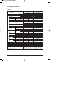
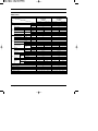
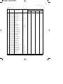
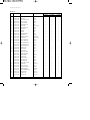
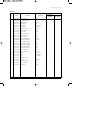
ROOM AIR CONDITIONER
INDOOR UNIT
OUTDOOR UNIT
AS18WJWB
AS18WJWD
AS18WJWE
AST18WJWB
AST18WJWE
AS24W6WB
AS24W6WE
AST24W6WB
AST24W6WE
SC18ZWJ
SC24ZW6
US18WJWB
US18WJWD
US18WJWE
UST18WJWB
UST18WJWE
US24W6WB
US24W6WE
UST24W6WB
UST24W6WE
SC18ZWJX
SC24ZW6X
SERVICE
AIR CONDITIONER
Manual
CONTENTS
1. Product Specifications
2. Operating Instructions & Installation
3. Disassembly and Reassembly
4. Refrigerating Cycle Diagram
5. Set Up the Model Option
6. Troubleshooting
7. Exploded Views and Parts List
8. Block Diagram
9. Wiring Diagram
1. Product Specifications
1-1 Table
AS18WJWB
AST18WJWB
Model
Item
Indoor unit
Type
Outdoor unit
Indoor unit
Wall-mounted
Cooling
Outdoor unit
Wall-mounted
kcal/h(1)
4,000
5,050
BTU/h(2)
18,000
24,000
\/h
Dehumidifying
Performance
AS24W6WB
AST24W6WB
1.9
2.7
Air Volume
Cooling
m3/min
13.5
25
14.4
45
Noise
Cooling
dB
45/43/41
58/58
46/44/42
61/61
Energy Efficiency
Power
Power Consumption
BTU/Wh(1)
7.05
BTU/Wh(2)
9.47
9.60
ø-V-Hz
1-220-60
1-220-60
2.25(1)
2.85(1)
1.9(2)
2.5(2)
10.1
13.2(1)
8.8
11.5(2)
%
98.0
98.0
A
47
65
m
-
-
-
-
kW
7.03
(1)
Operating Current
Power
Power Factor
A
Cooling
Starting Current
Length
Power Cord
Number of Core Wire
Capacity
Outer Dimension
Width x Height
x Depth
Weight
Refrigerant Pipe
-
A
1,065 x 298 x 218
790 x 548 x 285
1,065 x 298 x 218
880 x 638 x 310
inch
41.9 x 11.7 x 8.6
31.1 x 21.6 x 11.2
41.9 x 11.7 x 8.6
34.6 x 25.1 x 12.2
kg
13
39
13
64
ø6.35 x 5
Motor
Gas
mm x L(m)
ø12.7 x 5
ø15.88 x 5
D x L(mm)
ø18 x 2,000
ø18 x 2,000
Type
Rotary
Rotary
Induction Motor(PSC)
Induction Motor(PSC)
1,950
2,670
Rated Output
SUNISO-4GSD
Oil Type
Type
Blower
ø6.35 x 5
mm x L(m)
Type
Compressor
-
mm
Liquid
Drain Hose
Size
(2)
Motor
Propeller
Cross flow
Propeller
steel
steel
steel
steel
15
50
15
50
2R0W 16STEP
2ROW 24STEP
2R0W 16STEP
2ROW 28STEP
Type
Rated Output
W
Heat Exchanger
SUNISO-4GSD
Cross flow
CAPILLARY TUBE
Refrigerant Control unit
CAPILLARY TUBE
Freezer Oil Capacity
cc
600
800
Refrigerant to Change(R22)
g
1,200
1,400
MRA12068-12007
Protection Device(OLP)
Cooling Test Condition
Maximum Operation Condition
Samsung Electronics
Internal
INDOOR UNIT : DB29˚C WB19˚C
(2)
INDOOR UNIT : DB27˚C WB19˚C
OUTDOOR UNIT : DB46˚C WB24˚C
OUTDOOR UNIT : DB35˚C WB24˚C
INDOOR UNIT : DB32˚C WB23˚C
OUTDOOR UNIT : DB54˚C WB24˚C
(1)
(2)
1
Table( cont.)
Model
Item
AS18WJWD
Indoor unit
Type
Cooling
5.1
18,000
1.9
Air Volume
Cooling
m3/min
13.5
25
Noise
Cooling
dB
45/43/41
58/58
Energy Efficiency
Cooling
Power
Power
kW
BTU/h
\/h
Dehumidifying
Performance
W/W
2.76
BTU/Wh
9.73
ø-V-Hz
1-200/220-50
Power Consumption
Cooling
kW
1.85
Operating Current
Cooling
A
8.8
Power Factor
Cooling
%
94
A
42
m
-
Starting Current
Length
Power Cord
Number of Core Wire
Capacity
Outer Dimension
Width x Height
x Depth
Weight
Refrigerant Pipe
Size
A
-
mm
1,065 x 298 x 218
790 x 548 x 285
inch
41.9 x 11.7 x 8.6
31.1 x 21.6 x 11.2
kg
13
39
Liquid
mm x L(m)
Gas
mm x L(m)
ø12.7 x 5
D x L(mm)
ø18 x 2,000
Drain Hose
ø6.35 x 5
Type
Compressor
Motor
Rotary
Type
Induction Motor(PSC)
Rated Output
1,895
Oil Type
SUNISO-4GSD
Type
Blower
Motor
Type
Rated Output
W
Heat Exchanger
Refrigerant Control unit
Cross flow
Propeller
steel
steel
15
50
2R0W 16STEP
2ROW 24STEP
CAPILLARY TUBE
Freezer Oil Capacity
cc
Refrigerant to Change(R22)
g
Protection Device(OLP)
2
Outdoor unit
Wall-mounted
600
1,200
Internal
Cooling Test Condition
NDOOR UNIT : DB27˚C WB19˚C
OUTDOOR UNIT : DB35˚C WB24˚C
Maximum Operation Condition
NDOOR UNIT : DB32˚C WB23˚C
OUTDOOR UNIT : DB54˚C WB24˚C
Samsung Electronics
Table( cont.)
AS18WJWE
AST18WJWE
SC18ZWJ
Model
Item
Indoor unit
Type
Indoor unit
Air Volume
Cooling
Noise
Cooling
Energy Efficiency
Cooling
Power
Outdoor unit
Wall-mounted
kW
5.1
6.8
BTU/h
18,000
24,000
\/h
Dehumidifying
1.9
m3/min
13.5
dB
45/43/41
W/W
2.7
25
14.4
45
58/58
46/44/42
61/61
2.62
2.72
BTU/Wh
9.23
9.60
ø-V-Hz
1-220/240-50
1-220/240-50
Power Consumption
Cooling
kW
1.95
2.5
Operating Current
Cooling
A
9.5
12
Power Factor
Cooling
%
97
91.4
A
40
82
m
-
-
-
-
-
-
Starting Current
Power
Outdoor unit
Wall-mounted
Cooling
Performance
AS24W6WE
AST24W6WE
SC24ZW6
Length
Power Cord
Number of Core Wire
Capacity
Outer Dimension
Width x Height
x Depth
Weight
Refrigerant Pipe
A
mm
1,065 x 298 x 218
790 x 548 x 285
1,065 x 298 x 218
880 x 638 x 310
inch
41.9 x 11.7 x 8.6
31.1 x 21.6 x 11.2
41.9 x 11.7 x 8.6
34.6 x 25.1 x 12.2
kg
13
39
13
64
Liquid
mm x L(m)
ø6.35 x 5
ø6.35 x 5
Gas
mm x L(m)
ø12.7 x 5
ø15.88 x 5
D x L(mm)
ø18 x 2,000
ø18 x 2,000
Drain Hose
Type
Compressor
Size
Motor
Type
Rotary
Rotary
Induction Motor(PSC)
Induction Motor(PSC)
Rated Output
Oil Type
Type
Blower
Motor
Type
Rated Output
W
Heat Exchanger
Refrigerant Control unit
Freezer Oil Capacity
cc
Refrigerant to Change(R22)
g
Protection Device(OLP)
2,120
2,740
SUNISO-4GSD
SUNISO-4GSD
Cross flow
Propeller
Cross flow
Propeller
steel
steel
steel
steel
15
50
15
50
2R0W 16STEP
2ROW 24STEP
2R0W 16STEP
2ROW 28STEP
CAPILLARY TUBE
CAPILLARY TUBE
600
900
1,100
1,450
Internal
Internal
Cooling Test Condition
NDOOR UNIT : DB27˚C WB19˚C
OUTDOOR UNIT : DB35˚C WB24˚C
Maximum Operation Condition
NDOOR UNIT : DB32˚C WB23˚C
OUTDOOR UNIT : DB54˚C WB24˚C
Samsung Electronics
3
1-2 Pressure Graph
■ 18K BTU
Low Pressure Distribution(Cooling mode)
10
Low pressure(kg/cm G)
8
Indoor Temp.( C)
DB32.4 / WB24.0
DB30.6 / WB22.5
DB27.0 / WB19.0
DB24.0 / WB17.0
DB21.0 / WB15.0
6
4
2
0
25.0
35.0
45.0
55.0
Outdoor Temp.(DB C)
■ 24K BTU
Low Pressure Distribution(Cooling mode)
10
Low pressure(kg/cm G)
8
Indoor Temp.( C)
DB32.4 / WB24.0
DB30.6 / WB22.5
DB27.0 / WB19.0
DB24.0 / WB17.0
DB21.0 / WB15.0
6
4
2
0
25.0
35.0
45.0
55.0
Outdoor Temp.(DB C)
4
Samsung Electronics
2. Operating Instructions & Installation
2-1 The Feature of Key in remote control
No
BUTTON
FUNCTION
On/Off button.
Press the
button to stop or run the air conditioner.
1
(UP)
Temperature adjustment button(UP).
To increase the temperature by the pressing the temperature button.
(DOWN)
Temperature adjustment button(DOWN).
To decrease the temperature by the pressing the temperature button.
2
3
Mode selection button.
Each time you press this button,
Mode is changed in the following order.
: Auto Mode
: Dry Mode
: Cool Mode
: Fan Mode
Fan speed adjustment button.
Each time you press this button, FAN SPEED is changed in the following order.
Automatic(rotated :
4
)
Low
Medium
High
Turbo(Maximum)
5
Flap button.
It adjusts the airflow to upward and downward.
6
Turbo button.
The air conditioner cools or heats the room as quickly as possible.
After 30minutes, the air conditioner is reset automatically to the previous mode.
7
Energy saving button.
If you wish to save energy when using your air conditioner, select the Energy saving
mode with the
button.
8
Sleep button.
The sleep timer can be used when you are cooling or heating your room to switch the air conditioner
off automatically after a period of 6 hours.
9
On Timer button.
The On Timer enables you to switch on the air conditioner automatically after
a given period of time that is from 1 hour to 24 hours.
To set the operating time, press the
button one or more times until the required
time display.
Samsung Electronics
5
Operating Instructions & Installation
No
BUTTON
FUNCTION
10
Off Timer button.
The Off Timer enables you to switch off the air conditioner automatically after
a given period of time that is from 1 hour to 24 hours.
To set the operating time, press the
button one or more times until the required
time display.
11
Timer Set/Cancel button.
After setting On Timer or Off Timer, press the
button to set it completely.
And press the
button again to cancel On Timer or Off Timer set.
12
Battery life indicator.
If you want to check the battery life, press the
button.
The longer will remain the battery life.
If one battery life indicator remains, replace new batteries.
6
Samsung Electronics
2-2 Details for Operation Property
1.
AUTO MODE : In this mode, operation COOL mode is
selected automatically by the difference between the
setting and room temperature.
Operation Type
Cool Operation
6.
FAN SPEED : Fan speed automatically varies depending
on both the difference between setting and the room temperature.
Can set up the fan speed in COOL,FAN mode.
7.
COMPULSORY OPERATION :
For operating the air conditioner without the remote
control.
*The operating is the same function that AUTO MODE in
the remote control.
8.
FLAP : BLADE-H is rotated vertically by the stepping
motor.
*Flap Set : Press the
button under the remote control
is displayed on LCD the
and the blades move up and
down. If the one more time press the
button, blades
location is stop.
9.
SETTING THE ON/OFF TIMER. :
*ON TIMER : The On Timer enables you to switch on the
air conditioner automatically after a given period of time.
You can set the period of time from 1 hour to 24 hours.
*OFF TIMER : The Off Timer enables you to switch off
the air conditioner automatically after a given period of
time. You can set the period of time from 1 hour to 24
hours.
Room Temp.
Tr ≥ Ts+1.0°C
Compressor ON
Tr ≤ Ts
Compressor OFF
Ts : Setting temperature.
2.
3.
4.
5.
COOL MODE : The unit operates according to the
difference between the setting and room temperature.
(16°C~30°C)
DRY MODE : Has 4 states, each determined by room
temperature.
The unit operates in DRY mode.
*Compressor ON/OFF time is controlled compulsorily
(can not set up the fan speed, always breeze).
*Protective function : Low temperature release.
(Prevention against freeze)
TURBO MODE : This mode is available in AUTO, COOL,
DRY, FAN MODE.
When this button is pressed at first, the air conditioner is
operated "powerful" state for 30 minutes regardless of the
setting temperature, room temperature.
When this button is pressed again, or when the operating
time is 30 minutes, turbo operation mode is canceled and
returned to the previous mode.
*But, if you press the TURBO button in DRY or FAN
mode that is changed with AUTO mode automatically.
10. BUZZER SOUND : Whenever the On/Off button is
pressed or whenever change occurs to the condition
which is set up or select, the compulsory operation mode,
buzzer is sounded "beep".
SLEEP MODE : Sleep mode is available only in COOL
mode.
The operation will stop after 6 hours.
*In COOL mode : The setting temperature is automatically raised by 1°C each 1hour When the temperature has
been raised by total of 2°C, that temperature is
maintained.
Samsung Electronics
7
2-3 Installation
2-3-1 Before Installation
Keep the air conditioner drain hose outlet and inlet free from its surroundings.
In case of breakdown, keep the symmetry and fix it to prevent vibration.
The pipe length shall meet the standard as far as possible.
2-3-2 Installation Procedure
■ Location
Install the product in an area to guarantee the best cooling effect, convenience of piping and electric work, and inexistence of
vibration or wind in the vicinity.
■ Wall Drilling
Drill the wall downward in a diameter of 60 to 65mm.
■ Fixing Indoor Unit & Outdoor Unit
Fix the air conditioner hard enough so that it can not fall to the ground. On the roadside, the outdoor unit shall be installed 2m
above ground and kept away from pedestrians to prevent direct exposure to hot wind.
■ Pipe Spooling & Connecting
You shall cut the pipe straightly with a pipe cutter and grind all the burrs of the cut surface.
Pipe expansion may continue until the pipe surface becomes uneven or torn apart.
Be sure to use a torque wrench to tighten pipes or flare nuts.
<Torque & Depth>
Outer Diameter(D)
Torque(kgf.cm)
Depth(A)
6.35mm(1/4")
140~170
1.3mm
12.70mm(1/2")
380~420
2.0mm
15.88mm(5/8")
440~480
2.2mm
D
A
■ Leak Test
Put an inert gas like nitrogen in the outdoor unit pipe and put soap bubbles or other test liquids on the pipe surface for the leak test.
■ Drain Hose Connecting
Install the drain hose downward to drain water naturally. Be sure to pour water into the hose to check if it drains well.
■ Electric & Earth Work
Electric and earth work shall meet the "Electric Facility Technology Standard" and the "Internal Wire Regulation" of the Electric
Business Laws.
■ Inspection & Trial Run
Upon completion of the tests, you shall make a trial run while you explain the main functions of the air conditioner to finish the
installation.
8
Samsung Electronics
2-4 Installation Diagram of Indoor Unit and Outdoor Unit
2-4-1 Air-Purge Procedure
1) Connect each assembly pipe to the appropriate
valve on the outdoor unit and tighten the flare nut.
Indoor unit
Outdoor unit
A
Gas pipe side
C
B
Liquid pipe side
D
2) Connect the charging hose of low pressure side
of manifold gauge to the packed valve having a
service port (3/8" Packed valve) as shown at the
figure.
3) Open the valve of the low pressure side of
manifold gauge counter-clockwise.
4) Purge the air from the system using vacuum
pump for about 30 minutes.
- After that, please recheck that pressure is
stabilization.
- Close the valve of the low pressure side of
manifold gauge clockwise.
- Remove the hose of the low pressure side
of manifold gauge.
5) Set valve cork of both liquid side and gas side of
packed valve to the open position.
Vacuum Pump
6) Mount the valve stem nuts to the 2-Way and
3-Way valve. And mount the service port cap to
3-Way valve.
A
(gas)
7) Check for gas leakage.
- At this time, especially check for gas
leakage from the 3-Way valve’s stem nuts,
and from the service port cap.
B
(liquid)
Valve stem
Stem cap
Samsung Electronics
9
Operating Instructions & Installation
2-4-2 Refrigerant Refill(R22)
Refill an air conditioner with refrigerant when refrigerant has been leaked at installing or using.
1) Purge air(for new installation only).
2) Turn the 3-Way valve clockwise to close,
connect the pressure gauge (low pressure side)
to the service valve, and open the 3-Way valve
again.
Suspension hook
Compound
gauge
High
pressure
gauge
Hand
wheel
3) Connect the tank to refill with refrigerant.
4) Set the unit to cool operation mode.
Finger tight
fittings
For mounting
other and of
hose when
not in use
Connected to
high pressure
side
Charging line
5) Check the pressure indicated by the pressure
gauge(low pressure side).
* Standard pressure is should be 4.5~5.5kg/cm2
in a regular, high operation mode.
R22
6) Open the refrigerant tank and fill with refrigerant
until the rated pressure is reached.
* It is recommended not to pour the refrigerant
in too quickly, but gradually while operating a
pressure valve.
7) Stop operation of the air conditioner.
8) Close the 3-Way valve, disconnect the
pressure gauge, and open the 3-Way valve
again.
9) Close the cap of each valve.
10
Samsung Electronics
Operating Instructions & Installation
2-4-3 "Pump down" Procedure
Pump down will be carried out when an evaporator is replaced or when the unit is relocated in another area.
1) Remove the caps from the 2-Way valve and the
3-Way valve.
2) Turn the 3-Way valve clockwise to close and
connect a pressure gauge (low pressure side)
to the service valve, and open the 3-Way valve
again.
3-Way Valve
2-Way Valve
3) Set the unit to cool operation mode.
(Check if the compressor is operating.)
4) Turn the 2-Way valve clockwise to close.
5) When the pressure gauge indicates "0" turn the
3-Way valve clockwise to close.
6) Stop operation of the air conditioner.
7) Close the cap of each valve.
Relocation of the air conditioner
• Refer to this procedure when the unit is relocated.
• Carry out the pump down procedure (refer to the details of 'pump down').
• Remove the power cord.
• Disconnect the assembly cable from the indoor and outdoor units.
• Remove the flare nut connecting the indoor unit and the pipe.
• At this time, cover the pipe of the indoor unit and the other pipe using a cap or vinyl plug to avoid foreign
material entering.
• Disconnect the pipe connected to the outdoor unit.
At this time, cover the valve of the outdoor unit and the other pipe using a cap or vinyl plug to avoid foreign
material entering.
• Make sure you do not bend the connection pipes in the middle and store together with the cables.
• Move the indoor and outdoor units to a new location.
• Remove the mounting plate for the indoor unit and move it to a new location.
Samsung Electronics
11
3. Disassembly and Reassembly
Stop operation of the air conditioner and remove the power cord before repairing the unit.
3-1 Indoor Unit
No
Parts
1
Front Grille
Procedure
Remark
1) Stop the air conditioner operation and
shut off the main power.
2) Open the Front Grille by pulling right and
left sides of the hook.
3) Loosen 1 of the right screw and detach
the Terminal Cover.
4) Detach the thermistor from the Front
Grille.
5) Loosen 3 fixing screws of Front Grille.
12
Samsung Electronics
Disassembly and Reassembly
No
Parts
Procedure
Remark
6) Unlock 3 hooks to fix Panel Front and
Tray Drain.
7) Unlock 3 hooks to fix Panel Front and
Back-Body.
2
Control-In
(Main PCB)
1) Take all the connector of PCB upper side
out. (Inclusion Power Cord)
2) Detach the outdoor unit connection wire
from the Terminal Block.
3) Loosen 4 fixing screws of Ass'y Control-In.
3
Tray Drain
1) Pull Tray Drain out from the Back Body.
Samsung Electronics
13
Disassembly and Reassembly
No
Parts
4
Heat Exchanger
Procedure
Remark
1) Loosen 2 fixing earth screws of right side.
2) Detach the Connection Pipe.
3) Detach the Holder Pipe at the rear side.
4) Loosen the 4 fixing screws of right and left
side.
5) Lifting the Heat Exchanger up a little to
push the up side for separation from the
indoor unit.
5
14
Fan Motor
&
Cross Fan
1) Loosen the fixing screw.
2) Detach the Fan Motor from the Fan.
3) Detach the Fan From the left Holder
Bearing.
Samsung Electronics
3-2 Outdoor Unit
■ 18K BTU
No
Parts
1
Common Work
Procedure
Remark
1) Loosen the fixing screw of the
Cover Control.
2) Loosen the fixing screws on right and left,
back Cabinet-Side edge and a fixing screw
on the Cabinet-Front lower to detach the
Cabinet-Front.
3) Loosen the fixing screws of the
Ass'y-Control Out.
4) Loosen the fixing screws of the
Cabinet-Side RH.
5) Loosen the fixing screws of the
Cabinet-Side LF.
Samsung Electronics
15
Disassembly and Reassembly
No
Parts
2
Fan & Motor
3
Heat Exchanger
4
Compressor
Procedure
Remark
1) Detach the Nut Flange.(Turn counterclockwise because the screw is right-handed)
2) Detach the Fan.
3) Loosen 4 fixing screws to detach
the Motor.
1) Loosen 3 fixing screws of the Bar Steel.
2) Loosen 2 fixing screws on both sides.
3) Disassemble the pipe in both inlet and
outlet with welding torch.
4) Detach the Heat Exchanger.
1) Loosen the Terminal Cover nut to open the
Terminal Cover.
2) Disassemble the cloth sound felt.
3) Disassemble the pipe in both inlet and
outlet of the Compressor with welding
torch.
4) Loosen the 3 bolts at the bottom.
5) Detach the Compressor.
16
Samsung Electronics
Disassembly and Reassembly
■ 24K BTU
No
Parts
1
Common Work
Procedure
Remark
1) Loosen the fixing screw of the Cover
Control.
2) Loosen the fixing screws of the
Cabinet-Upper.
3) Loosen the fixing screws of the
Cabinet-Side RH.
4) Loosen the fixing screws of the
Cabinet-Side LF.
5) Loosen the fixing screws of the
Ass'y Control Out.
Samsung Electronics
17
Disassembly and Reassembly
No
Parts
2
Fan & Motor
3
Heat Exchanger
Procedure
Remark
1) Remove the Nut Flange (Turn to the
clockwise).
2) Detach the Fan.
3) Loosen 4 fixing screws to detach the
Motor.
1) Loosen 2 fixing screws on both side.
2) Disassemble the pipe in both inlet and
outlet with welding torch.
3) Detach the Heat Exchanger.
4
Compressor
1) Loosen the Terminal Cover to open the
Terminal Cover.
2) Disassemble the Cloth Sound Felt.
3) Disassemble the pipe in both inlet and
outlet of the Compressor with welding
torch.
4) Loosen 3 bolts at the bottom.
5) Detach the Compressor.
18
Samsung Electronics
4. Refrigerating Cycle Diagram
Indoor Unit
Outdoor Unit
Capillary tube
T1
2-Way valve
Cross fan
Heat
Exchanger
(Evaporator)
Heat
Exchanger
(Condenser)
Propeller fan
Liquid side
T2
Gas side
3-Way valve
Compressor
Cooling
Gas leak check point
Samsung Electronics
19
4-1 Refrigerant Cycle Characteristic
4-1-1 Capacity Distributions
Capacity Distributions according to indoor and outdoor temperature variation.
■ COOLING MODE
- Indoor Temp. Variation : 21.0˚C ~ 32.4˚C
- Outdoor Temp. Variation : 25.0˚C ~ 55.0˚C
■ 18K BTU
Cooling Capacity Distribution
Cooling Capacity(Btu/h)
30,000
Indoor Temp.( C)
DB32.4 / WB24.0
DB30.6 / WB22.5
DB27.0 / WB19.0
DB24.0 / WB17.0
DB21.0 / WB15.0
20,000
10,000
25.0
35.0
45.0
55.0
Outdoor Temp.(DB C)
■ 24K BTU
Cooling Capacity Distribution
Cooling Capacity(Btu/h)
30,000
20,000
Indoor Temp.( C)
DB32.4 / WB24.0
DB30.6 / WB22.5
DB27.0 / WB19.0
DB24.0 / WB17.0
DB21.0 / WB15.0
10,000
25.0
35.0
45.0
55.0
Outdoor Temp.(DB C)
20
Samsung Electronics
Refrigerating Cycle Diagram
4-1-2 Power Consumption Distributions
Power Consumption Distributions according to indoor and outdoor temperature variation.
■ COOLING MODE
- Indoor Temp. Variation : 21.0˚C ~ 32.4˚C
- Outdoor Temp. Variation : 25.0˚C ~ 55.0˚C
■ 18K BTU
Power consumption Distribution(Cooling mode)
4,000
Power consumption(W)
3,500
3,000
Indoor Temp.( C)
DB32.4 / WB24.0
DB30.6 / WB22.5
DB27.0 / WB19.0
DB24.0 / WB17.0
DB21.0 / WB15.0
2,500
2,000
1,500
1,000
25.0
35.0
45.0
55.0
Outdoor Temp.(DB C)
■ 24K BTU
Power consumption Distribution(Cooling mode)
4,000
Power consumption(W)
3,500
3,000
2,500
Indoor Temp.( C)
DB32.4 / WB24.0
DB30.6 / WB22.5
DB27.0 / WB19.0
DB24.0 / WB17.0
DB21.0 / WB15.0
2,000
1,500
1,000
25.0
35.0
45.0
55.0
Outdoor Temp.(DB C)
Samsung Electronics
21
5. Set Up the Model Option
5-1 Setting Option Setup Method
ex) Option No. :
(AST18WJWE)
Step 1 : Enter the Option Setup mode.
1st
Take out the batteries of remote control.
2nd
Press the temperature
insert the battery again.
3rd
Make sure the remocon display shown as
button simultaneously and
.
Step 2 : Enter the Option Setup mode and select your option according to the following procedure.
Feature
1
Display
Setting Option SEG1.
Push the
button to set the display panel to
.
Every time you push the button, the display panel reads
...
repeatedly.
2
Setting Option SEG2.
Push the
button to set the display panel to
.
Every time you push the button, the display panel reads
...
repeatedly.
3
3
1,4
Change it into the set display of Option SEG3 and SEG4
with the
2,5
4
button.
Setting Option SEG3.
Push the
button to set the display panel to
.
Every time you push the button, the display panel reads
...
repeatedly.
5
Setting Option SEG4.
Push the
button to set the display panel to
.
Every time you push the button, the display panel reads
...
repeatedly.
22
Samsung Electronics
Set Up the Model Option
Feature
Display
6
Change it into the set display of Option SEG5 and SEG6
with the
button.
7
Setting Option SEG5.
Push the
button to set the display panel to
.
Every time you push the button, the display panel reads
...
repeatedly.
8
Setting Option SEG6.
Push the
button to set the display panel to
.
Every time you push the button, the display panel reads
...
repeatedly.
6,9
7,10
8,11
9
Change it into the set display of Option SEG7 and SEG8
with the
button.
10
Setting Option SEG7.
Push the
button to set the display panel to
.
Every time you push the button, the display panel reads
...
repeatedly.
11
Setting Option SEG8.
Push the
button to set the display panel to
.
Every time you push the button, the display panel reads
...
repeatedly.
12
Change it into the set display of Option SEG9 and SEG10
with the
12
13
14
button.
13
Setting Option SEG9.
Push the
button to set the display panel to
.
Every time you push the button, the display panel reads
...
repeatedly.
14
Setting Option SEG10.
Push the
button to set the display panel to
.
Every time you push the button, the display panel reads
...
repeatedly.
Samsung Electronics
23
Set Up the Model Option
Step 3 : Upon completion of the selection, check you made right selections.
Whenever you press the
button, the set Option will be displayed.
Step 4 : Pressing the ON/OFF button (
)
When pressing the operation ON/OFF key with the direction of remote control for unit, the sound "Ding" is heard and the
OPERATION LED lamp is flickering at the same time, then the input of option is completed. (If the "ding" sound isn't heard,
try again pressing the ON/OFF button.)
Step 5 : Unit operation test-run
First, Remove the battery from the remote control.
Second, Re-insert the battery into the remote control.
Third, Press ON/OFF (
) key with the direction of remote control for set.
• Error Mode
24
1st
If all lamps of indoor unit are flickering, Plug out, plug in power plug again and press ON/OFF key to retry.
2nd
If the unit is not working properly or all lamps are continuously flickering after setting the option code, see if the
correct option code is set up for its model.
Samsung Electronics
5-2 Table of the option Code
Option Code
Model
SEG1
SEG2
SEG3
SEG4
SEG5
SEG6
SEG7
SEG8
SEG9
SEG10
AS18WJWB
AS18WJWE
AST18WJWB
AST18WJWE
SC18ZWJ
6
0
0
0
0
5
0
2
2
E
AS18WJWD
6
0
0
0
0
5
0
3
4
0
AS24W6WB
AS24W6WE
AST24W6WB
AST24W6WE
SC24ZW6
6
0
0
0
0
A
0
3
5
1
Samsung Electronics
25
6. Troubleshooting
Check the basic items first to judge if the problem was caused by breakdown or misuse. If none of the basic items are related to the
problem, please scrutinize the machine according to the 'Breakdown Diagnosis by Symptoms' method.
6-1 Basic Breakdown Diagnosis Items
1.
The input voltage should be rating voltage ±10% range.
The airconditioner may not operate properly if the voltage is out of this range.
2.
Is the link cable linking the indoor unit and the outdoor unit linked properly?
The indoor unit and the outdoor unit shall be linked by 5 cables.
Check the terminals if the indoor unit and outdoor unit are properly linked by the same number of cables.
Otherwise the airconditioner may not operate properly.
3.
When a problem occurs due to the contents illustrated in the table below it is a symptom not related to the malfunction of the
airconditioner.
No
26
Operation of air conditioner
Explanation
1
The OPERATION indication LED(GREEN) blinks when a
power plug of the indoor unit is plugged in for the first time.
It indicates power is on. The LED stops blinking if the operation ON/OFF button on the remote control unit is pushed.
2
In a COOL operation mode, the compressor does not
operate at a room temperature higher than the setting
temperature that the INDOOR FAN should operate.
In a HEAT operation mode, the compressor does not operate
at a room temperature lower than the setting temperature
that indoor fan should operate.
In happens after a delay of 3 minutes when the compressor
is reoperated. The same phenomenon occurs when a power
is on.
As a phenomenon that the compressor is reoperated after a
delay of 3 minutes, the indoor fan is adjusted automatically
with reference to a temperature of the air blew.
3
Fan speed setting is not allowed in DRY(
The speed of the indoor fan is set to LL in DRY mode.
Fan speed is selected automatically in AUTO mode.
4
Compressor stops operation intermittently in DRY(
mode.
5
Compressor of the outdoor unit is operating although it is
turned off in a HEAT mode.
When the unit is turned off while de-ice is activated,
the compressor continues operation for up to 9 minutes
(maximum) until the deice is completed.
6
Timer LED(GREEN) of the indoor unit lights up and the
air conditioner does not operate.
Timer is being activated and the unit is in ready mode.
The unit operates normally if the timer operation is cancelled.
7
The compressor and indoor fan stop intermittently in
HEAT mode.
The compressor and indoor fan stop intermittently if room
temperature exceeds a setting temperature in order to protect
the compressor from overheated air in a HEAT mode.
8
Indoor fan and outdoor fan stop operation intermittently
in a HEAT mode.
The compressor operates in a reverse cycle to remove
exterior ice in a HEAT mode, and indoor fan and outdoor fan
do not operate intermittently for within 20% of the total heater
operation
9
The compressor stops intermittently in a COOL mode or
DRY mode, and fan speed of the indoor unit decreases.
The compressor stops intermittently or the fan speed of the
indoor unit decreases to prevent inside/outside air frozen
depending on the inside/outside air temperature.
) mode.
)
Compressor operation is controlled automatically in DRY
mode depending on the room temperature and humidity.
Samsung Electronics
6-2 Trouble check in the initial status
6-2-1 Diagnosis and marking of the part in trouble.
Please check the air conditioner operation status and write the check result in the chart in the room.
LAMP
OPERATION
Description
TIMER
TURBO
Indoor unit room temperature sensor error
(open or short)
Indoor unit heat exchanger temperature sensor error
(open or short)
Indoor fan motor mal function
EEPROM error
Option error
(option wasn't set up or option data error)
: Lamp off
: Lamp flickering
6-2-2 Operation with abnormal motion
No
1
2
Abnormal condition
No response from
the remote control
operation signal.
Unable to operate the
outdoor unit
Samsung Electronics
Inspection
• Plug out and plug in 5 seconds later.
• Press the TURBO button with the
remote control.
• In 3 minutes, check the voltage
between the indoor unit terminal
block N1 and 1.
Initial Diagnosis
Able to operate the
remote control.
OK
Unable to operate
the remote control.
Press the
button in the indoor unit.
• If it operates, the remote control and
indoor unit receiver are in trouble.
• If not, the indoor unit is in trouble.
AC200V ~ AC240V
Problem with the outdoor unit or PCB
No power source
displayed.
Problem with the relay (RY71) or PCB
27
6-3 Breakdown diagnosis by symptoms
6-3-1 No Power (completely dead)-Initial diagnosis
1. Checklist :
1) Is input voltage normal?
2) Is AC power linked correctly?
3) Is input voltage of DC regulator IC KA7805 (IC02) normal? (11VDC-12.5VDC)
4) Is output voltage of DC regulator IC KA7805 (IC02) normal? (4.5VDC-5.5VDC)
2. Troubleshooting procedure
Unplug the power cord and plug it after 5 seconds
Press the Power Button on
the remote control unit to operate the air
conditioner
operate
◆ Check the display board
does not operate
◆ Check the indoor unit control board
Check whether two wires
of power cord are connected correctly to the
terminal block and control board.
No
Reconnect wires correctly
Yes
Check whether the fuse
on the control board is normal.
F701: 3.15[A]/250[V]
No
Replace fuse
Yes
Check the output of
SMPS on the control board.
Input power: AC230±15%[V]
IC02 Input: DC12[V]
IC02 output: DC5[V]
No
Replace the control board
Yes
◆ Check the setting temperature
28
Samsung Electronics
Troubleshooting
6-3-2 When the Indoor Unit Fan Does Not Operate. (Initial Diagnosis)
1. Checklist :
1) Is the indoor unit fan motor properly connected with the connector (CN72)?
2) Is the AC voltage correct?
3) Is HALL IC in indoor fan motor properly connected with the connector (CN44)?
4) Is the running capacitor (CR71) properly connected with PCB board?
2. Troubleshooting procedure
After unplugging out the power cord should
be reconnected within 5 seconds.
Yes
No
Check as in the procedure
"No power parts"
Does the OPERATION lamp blink?
Yes
No
Micom is
out of order.
Micom
should be replaced
No
PCB is
out of order.
PCB should be
replaced.
Does the Solid State Relay(SS71) work properly?
Test rod location
+
-
SS71-
SS71-
Normal
Voltage
12V
Yes
Is the supply voltage of the fan motor sufficient?
Test rod location
PCB CN72
Condition
pin #3 and #5
Fan operate
Normal
Voltage
About AC
180V
Motor Fan-Capacitor is out of order
Replace Motor
Fan-Capacitor
Yes
Fan motor
is out of order.
Samsung Electronics
Fan motor
should be replaced.
29
Troubleshooting
6-3-3 When the Outdoor Unit Does Not Operate. (Initial Diagnosis)
1. Checklist :
1) Is input voltage normal?
2) Is the set temperature of the remote control higher than room temperature in COOL mode?
3) Is the set temperature of the remote control lower than room temperature in HEAT mode?
4) Is the POWER IN connector (CN71) linked correctly?
5) Is the outdoor unit properly connected with the TERMINAL BLOCK connector(N1, L1, 1, 2, 3, 4)?
2. Troubleshooting procedure
After unplugging out the power cord should be
reconnected within 5 seconds.
No
Check as in the procedure
"No Power parts"
Does the OPERATION lamp blink
Yes
Room temperature sensor is
out of order
Yes
Does the timer lamp blink during operation?
!
No
@
#
No
Is the power relay RY71 operated by adjusting
the room temperature?
Test rod location
+
-
Condition
IC04 Pin No.38
GND
RY71 ON
PCB should be checked.
Micom is
out of order.
Normal
Voltage
PCB should be checked.
DC4.8V
Yes
Is rating voltage ±10% range applied relay between
Terminal block No. N1 and No. 1
No
Power relay is
out of order
Power relay should be
replaced.
Yes
Outdoor unit is out of order.
No
!
Yes
@
Is the room sensor normal register?
10°C
20°C
30°C
17.96kΩ
12.09kΩ
8.3kΩ
#
30
Samsung Electronics
Troubleshooting
6-3-4 When the UP/DOWN Louver Motor Does Not Operate. (Initial Diagnosis)
1. Checklist :
1) Is input voltage normal?
2) Is the UP/DOWN louver motor properly connected with the connector (CN61)?
2. Troubleshooting procedure
Remove power cord and plug in again in approx.
5 seconds.
No
Does the OPERATION lamp blink?
Check as in the procedure
"No Power parts".
Yes
Does operation start when
swing button of the remote control unit
pushed?
Yes
Normal
No
Voltage at pin #57~#60
of micom (IC04) change?
(Squarewave)
No
Micom (IC04) is faulty.
Yes
Voltage at pin #13 ~ #16 of
IC06(ULN2003A) change?
(Squarewave)
No
Driver IC06/08 (ULN2003A) is faulty.
Yes
UP/DOWN louver motor is faulty.
Samsung Electronics
31
Troubleshooting
6-3-5 In the HEAT mode, When there is no warm air current. Check this fist;
1) Is the set temperature of Remote Control lower than room temperature in Heat mode?
2) Is the Indoor PCB properly connected with the CN71 connector?
After training on, the heating operation
should start in 5 minutes.
No
Is the number #38 of Micom (IC04)
DC5.0V?
No
Abnormal Micom
Yes
Is the number checking
#13 of IC05 (ULN2003A) LOW?
No
Abnormal Micom
Yes
Is the voltage between
CN71 #1 and CN71 #5 rating voltage
±10% range
No
Abnormal IC05
Yes
Abnormal 4-Way valve of Outdoor Unit.
or connecting Cable
4-Way valve should be replaced
or connecting Cable Check.
32
No
Abnormal RY73
PCB should be replaced.
Samsung Electronics
Troubleshooting
6-3-6 Room temperature sensor failure
LAMP
OPERATION
Description
TIMER
TURBO
Indoor unit room temperature sensor error(open or short)
: Lamp off
: Lamp flickering
Detach the assembly sensor from the
ASS'Y PCB CN43 connector and measure
the sensor resistance with an ohmmeter (tester).
Is the sensor resistance value
10KΩ ±3% at the room temperature
of 25˚C?
No
ASS'Y Sensor Replace
SENSOR Resistance Value : 20˚C-12.09kΩ
SENSOR Resistance Value : 30˚C-8.31kΩ
SENSOR Resistance Value : 35˚C-6.94kΩ
SENSOR Resistance Value : 40˚C-5.83kΩ
Yes
Connect the sensor to CN43,
supply power, and measure the voltage of
#1 and #2 of the CN43 connector.
Yes
Poor ASS'Y PCB Replace
Below 0.5V?
No
Yes
Over 4.9V?
Poor ASS'Y PCB Replace
No
MICOM Error or Connector(CN43) check
Samsung Electronics
33
Troubleshooting
6-3-7 Room Pipe sensor failure
LAMP
OPERATION
Description
TIMER
TURBO
Indoor unit heat exchanger temperature sensor error
(open or short)
: Lamp off
: Lamp flickering
1. Check the assembly condition of the sensor connector(CN43) on the indoor unit Main PCB and if not assembled, reassemble the
connector accurately.
2. Detach the room pipe sensor connector(CN43) and check the resistance between connector 3 and 4.
Temperature(˚C)
Resistance Value(Kohm)
Temperature(˚C)
Resistance Value(Kohm)
15
14.68
30
8.31
20
12.09
35
6.94
25
10
40
5.83
Others
The data tolerance
is ±3%.
If the above data is not met, replace the room pipe sensor.
3. Assemble the room pipe sensor to PCB, plug in, and check the voltage of connector 3 and 4. If the resistance is below 0.5V or
over 4.9V, replace the indoor Main PCB. (short or disconnected in the PCB board)
6-3-8 When the remote control is not receiving.
1. Check if the connector was normally assembled.
2. Put the set in operation and check the voltage of No. 3(+) and No. 2(-) of the main PCB CN91 while operating the
remote control. When the voltage descends below 3V, the assembly module PCB is normal and the main PCB is poor.
Then replace the main PCB.
3. Replace the assembly display PCB because the module PCB is poor if the voltage between No. 2~3 of CN91
maintains 5V after the remote control starts operation.
34
Samsung Electronics
6-4 PCB Inspection Method
6-4-1 Pre-inspection Notices
1. Check if you pulled out the AC power plug when you eliminate the PCB or front panel.
2. Don't hold the PCB side not impose excessive force on it to eliminate the PCB.
3. Don't pull the lead wire but hold the whole housing to connect or disconnect a connector to the PCB.
6-4-2 Inspection Procedure
1. Check connector connection and peeling of PCB or bronze coating pattern when you think the PCB is broken.
2. The PCB is composed of the 3 parts.
● Main PCB Part : MICOM and surrounding circuit, relay, room fan motor driving circuit and control circuit, sensor driving circuit,
power circuit of DC12V and DC5V, and buzzer driving circuit.
● Display part : LED lamp
● Switch part : Switch
6-4-3 Detailed Inspection Procedure
No
Procedure
1
Plug out and pull the PCB
out of the electronic box.
Check the PCB fuse.
1) Is the fuse disconnected? (F701)
2
Supply power.
If the operating lamp
twinkles at this time,
the above 1)~3) have
no relation.
Checking the power voltage.
3
4
Press the ON/OFF button
and operate TURBO
mode.
But, exclude the
RESERVE operation.
Inspection Method
• Overcurrent
• Indoor Fan Motor Short
• AC Part Pattern Short of the MAIN PCB
1) Is the DB71input voltage AC200V~AC240V?
• Power Cord is fault, Fuse open. Wrong
Power Cable Wiring, AC Part is faulty.
2) Is the voltage between both terminals of the
C102 on the 2nd side of the transformer AC12V
±0.5V?
• Switching Trans or Power Circuit is faulty
3) Is the voltage between both terminals of OUT
and GND of IC02(KA78L05) DC5V ±0.5V?
• Power Circuit is faulty, Load Short
Checking the power voltage.
1) Check the voltage of the relay(RY71) coil(IC05 PIN
#11 and GND : 0V, PIN#6 and GND : 5V) during
operation(3 minutes after TURBO operation).
• Relay(RY71) Coil Disconnection, IC05 is
faulty
2) Check the voltage of both terminals of
terminal block 1 and N1 after 3 minute
operation.: AC220V
• Relay(RY71) Contact is faulty
Press the ON/OFF button. 1) Is the voltage over AC180V being imposed
on terminal #3 and #5 of the fan motor
1. FAN Speed [High]
connector(CN72)?
2. Continuous Operation
Samsung Electronics
Cause
• Fan Motor of the indoor is faulty
2) The fan motor of the indoor unit doesn't run.
• Fan Motor Connector(CN72) is faulty
3) The power voltage between terminal #3 and #5
of the connector(CN72) is 0V.
• ASS'Y Main PCB is faulty
• Connection is faulty
35
Troubleshooting
6-4-4 Temperature Sensor Feature Conversion Table(Room Temperature Sensor); 103AT
Temperature Sensor Resistance Temperature Sensor Resistance Temperature Sensor Resistance Temperature Sensor Resistance
[˚C]
[˚C]
[˚C]
[˚C]
[Kohm]
[Kohm]
[Kohm]
[Kohm]
70
69
68
67
66
65
64
63
62
61
60
2.229
2.296
2.365
2.437
2.512
2.589
2.669
2.752
2.838
2.928
3.021
49
48
47
46
45
44
43
42
41
40
4.300
4.444
4.594
4.749
4.912
5.080
5.256
5.439
5.630
5.828
29
28
27
26
25
24
23
22
21
20
8.622
8.944
9.281
9.632
10
10.380
10.780
11.200
11.630
12.090
9
8
7
6
5
4
3
2
1
0
18.700
19.480
20.290
21.150
22.050
22.990
23.900
25.030
26.130
27.280
59
58
57
56
55
54
53
52
51
50
3.116
3.216
3.319
3.426
3.537
3.652
3.772
3.897
4.026
4.161
39
38
37
36
35
34
33
32
31
30
6.033
6.246
6.468
6.699
6.941
7.192
7.455
7.729
8.015
8.313
19
18
17
16
15
14
13
12
11
10
12.560
13.060
13.570
14.120
14.680
15.280
15.900
16.550
17.240
17.960
-1
-2
-3
-4
-5
-6
-7
-8
-9
28.470
29.720
31.040
32.430
33.890
35.430
37.050
38.760
40.560
Temperature Sensor Characteristic Curve
Temperature
(˚C)
70
60
50
40
30
At the temperature of 25˚C(10KΩ)
20
10
0
-10
-9
5
10
15
20
25
30
35
40
Resistance Value (Kohm)
36
Samsung Electronics
6-5 Main Part Inspection Method
Part
Room Temperature Sensor
Room Fan Motor
Breakdown Inspection Method
Measure resistance with a tester
Normal
At the normal temperature 37kΩ~ 8.3kΩ(-7˚C~+30˚C) *Refer to Table 6-4-4.
Abnormal
∞, 0Ω . . . Open or Short
Measure the resistance between terminals of the connector (CN72) with a tester.
Normal
Abnormal
Outdoor Fan Motor
Abnormal
Samsung Electronics
Compare terminal
Resistance
Remark
Yellow, Blue
404.4Ω ± 10%
Main
Yellow, Red
340Ω ± 10%
Sub
∞, 0Ω . . . Open or Short
Measure the resistance between motor wires with a tester.
Normal
Stepping Motor
At the normal temperature (10˚C ~ 30˚C)
At the normal temperature (10˚C ~ 30˚C)
Compare terminal
Resistance
Remark
Yellow, Red
360Ω ± 10%
Main
Black, Yellow
328Ω ± 10%
Sub
∞, 0Ω . . . Open or Short
Measure the resistance between the red wire and each terminal wire with a tester.
Normal
About 300Ω at the normal temperature (20˚C ~ 30˚C)
Abnormal
∞, 0Ω . . . Open or Short
37
7. Exploded Views and Parts List
7-1 Indoor Unit
6
7
1
1-2
14
1-1
15
10
12
16
13
11
4
9
2
2-1
17
2-3
2-2
3-8
3-6
5-1
5
3-4
5-4
3
3-1
3-7
3-2
5-2
5-3
3-5
3-3
8
You can search for the updated part code
number through the ITSELF.
URL : http://itself.sec.samsung.co.kr
38
Samsung Electronics
Exploded Views and Parts List
■
Parts List
Q'TY
No.
Code No.
Description
Specification
AS18WJWB
AS18WJWE
AS18WJWD AST18WJW✳
SC18ZWJ
1
DB94-00615A
ASS'Y BACK BODY
ASS'Y
1
1
1
1
1-1
DB61-01974A
BODY BACK
HIPS
1
1
1
1
1-2
DB69-01039A
CUSHION-BACK BODY
FO-PS
1
1
1
1
2
DB96-03913A
ASS'Y CYCLE IN
ASS'Y
1
1
1
1
2-1
DB63-01065A
COVER-BEARING
ABS
1
1
1
1
2-2
DB60-00192A
SPACER-EVAP LOW
PVC
1
1
1
1
2-3
DB96-03754D
ASS'Y EVAP
1.5 SLIT 2x16
1
1
1
1
3
DB94-00616B
ASS'Y TRAY DRAIN
ASS'Y
1
1
1
1
3-1
DB63-01071A
TRAY-DRAIN
HIPS
1
1
1
1
3-2
DB61-01975B
BLADE-H
ABS
1
1
1
1
3-3
DB61-01976A
BLADE-V
PP
2
2
2
2
3-4
DB63-01066A
TRAY-STABILIZER
HIPS
1
1
1
1
3-5
DB69-01024A
INSU TRAY RH
FO-PS
1
1
1
1
3-6
DB73-00180A
RUBBER-CAP DRAIN
GUM-EPM
1
1
1
1
3-7
DB31-00285A
MOTOR-STEP
MSFCC20A01
1
1
1
1
3-8
DB94-00458B
ASS'Y DRAIN-HOSE
ASS'Y
1
1
1
1
4
DB93-02830H
ASS'Y CONTROL IN
ASS'Y
-
1
1
1
DB93-02830B
ASS'Y CONTROL IN
ASS'Y
1
-
-
-
5
DB92-00632E
ASS'Y PANEL FRONT
ASS'Y
-
-
1
-
DB92-00632F
ASS'Y PANEL FRONT
ASS'Y
1
1
-
-
DB92-00632C
ASS'Y PANEL FRONT
ASS'Y
-
-
-
1
5-1
DB64-01184B
PANEL FRONT
ABS
1
1
1
1
5-2
DB64-01182B
GRILLE-INLET
ABS
1
1
1
1
5-3
DB93-02867B
ASSY DISPLAY
ASS'Y
1
1
1
1
5-4
DB63-01186A
GUARD-AIR FILTER
PP
-
-
1
-
DB63-01186C
GUARD-AIR FILTER
PP
1
1
-
1
6
DB70-00505A
PLATE-HANGER
SGCC-P
1
1
1
1
7
DB61-01981A
HOLDER-PIPE
HIPS
1
1
1
1
8
DB63-01063A
COVER-CONTROL
HIPS
1
1
1
1
9
DB93-02532G
ASSY REMOCON
ASS'Y
-
-
1
-
DB93-02532A
ASSY REMOCON
ASS'Y
1
1
-
1
10
DB96-03817A
ASS'Y EVAP-SUPPORT
ASS'Y
1
1
1
1
11
DB31-00267A
MOTOR FAN
YFK 40 4C
1
1
1
1
12
DB94-00456B
ASS'Y-CROSS FAN
ASS'Y
1
1
1
1
13
DB97-02075A
ASS'Y-BOLT SPECIAL
M5xL6
1
1
1
1
14
DB73-00181A
RUBBER-BEARING
RUBBER
1
1
1
1
15
DB94-40007A
ASS'Y BEARING-MOTOR
ASS'Y
1
1
1
1
16
DB61-01977A
BRACKET-EVAP
SGCC-M
1
1
1
1
17
DB93-01638D
POWER CORD
250V,20A
1
-
1
1
DB93-01638E
POWER CORD
250V,20A
-
1
-
-
Samsung Electronics
39
Exploded Views and Parts List
■
Parts List
Q'TY
No.
Code No.
Description
Specification
AS24W6W✳
AST24W6W✳
SC24ZW6
1
DB94-00615A
ASS'Y BACK BODY
ASS'Y
1
1
1
1-1
DB61-01974A
BODY BACK
HIPS
1
1
1
1-2
DB69-01039A
CUSHION-BACK BODY
FO-PS
1
1
1
2
DB96-03809A
ASS'Y CYCLE IN
ASS'Y
1
1
1
2-1
DB63-01065A
COVER-BEARING
ABS
1
1
1
2-2
DB60-00192A
SPACER-EVAP LOW
PVC
1
1
1
2-3
DB96-03754C
ASS'Y EVAP
1.3 SLIT 2x16
1
1
1
3
DB94-00616B
ASS'Y TRAY DRAIN
ASS'Y
1
1
1
3-1
DB63-01071A
TRAY-DRAIN
HIPS
1
1
1
3-2
DB61-01975B
BLADE-H
ABS
1
1
1
3-3
DB61-01976A
BLADE-V
PP
2
2
2
3-4
DB63-01066A
TRAY-STABILIZER
HIPS
1
1
1
3-5
DB69-01024A
INSU TRAY RH
FO-PS
1
1
1
3-6
DB73-00180A
RUBBER-CAP DRAIN
GUM-EPM
1
1
1
3-7
DB31-00285A
MOTOR-STEP
MSFCC20A01
1
1
1
3-8
DB94-00458B
ASS'Y DRAIN-HOSE
ASS'Y
1
1
1
4
DB93-02830D
ASS'Y CONTROL IN
ASS'Y
1
1
1
5
DB92-00632E
ASS'Y PANEL FRONT
ASS'Y
-
1
-
DB92-00632F
ASS'Y PANEL FRONT
ASS'Y
1
-
-
DB92-00632C
ASS'Y PANEL FRONT
ASS'Y
-
-
1
DB64-01184B
PANEL FRONT
ABS
1
1
1
5-1
5-2
DB64-01182B
GRILLE-INLET
ABS
1
1
1
5-3
DB93-02867B
ASSY DISPLAY
ASS'Y
1
1
1
5-4
DB63-01186A
GUARD-AIR FILTER
PP
-
1
-
DB63-01186C
GUARD-AIR FILTER
PP
1
-
1
40
6
DB70-00505A
PLATE-HANGER
SGCC-P
1
1
1
7
DB61-01981A
HOLDER-PIPE
HIPS
1
1
1
8
DB63-01063A
COVER-CONTROL
HIPS
1
1
1
9
DB93-02532G
ASSY REMOCON
ASS'Y
-
1
-
DB93-02532A
ASSY REMOCON
ASS'Y
1
-
1
10
DB96-03817A
ASS'Y EVAP-SUPPORT
ASS'Y
1
1
1
11
DB31-00267A
MOTOR FAN
YFK 40 4C
1
1
1
12
DB94-00456B
ASS'Y-CROSS FAN
ASS'Y
1
1
1
13
DB97-02075A
ASS'Y-BOLT SPECIAL
M5xL6
1
1
1
14
DB73-00181A
RUBBER-BEARING
RUBBER
1
1
1
15
DB94-40007A
ASS'Y BEARING-MOTOR
ASS'Y
1
1
1
16
DB61-01977A
BRACKET-EVAP
SGCC-M
1
1
1
17
DB93-01638D
POWER CORD
250V,20A
-
-
-
DB93-01638E
POWER CORD
250V,20A
-
-
-
Samsung Electronics
MEMO
Samsung Electronics
41
7-2 Outdoor Unit
■ 18K BTU
14
21
18
14-2
19
14-1 14-3
16
20
10
3
9
8
11
3-2
7
13
12
6
3-1
15
4
17
1
2
5
42
Samsung Electronics
Exploded Views and Parts List
■
Parts List
Q'TY
No.
Code No.
Description
Specification
US18WJWB
UST18WJWB
US18WJWD
1
DB90-01711A
ASS'Y-CABI FRONT
ASS'Y
1
1
1
2
DB63-00847A
GUARD FAN
HIPS
1
1
1
3
DB90-01713A
ASS'Y-CABI SIDE LF
ASS'Y
1
1
1
3-1
DB64-00982A
CABINET-SIDE LF
SECC-P
1
1
1
3-2
DB64-00992A
HANDLE-LF
PP
1
1
1
4
DB90-01712A
ASS'Y-CABI SIDE RH
ASS'Y
1
1
1
5
DB63-01172A
COVER-CONTROL
ABS V0
1
1
1
6
DB90-01681A
ASS'Y BASE OUT
ASS'Y
-
-
1
DB90-01681B
ASS'Y BASE OUT
ASS'Y
1
1
-
7
DB61-02068A
BRACKET-VALVE
SECC-P
1
1
1
8
DB94-00638A
ASS'Y PARTITION
ASS'Y
1
1
1
9
DB61-01644A
BRACKET MOTOR
SGCC-M
1
1
1
10
DB97-02225B
ASS'Y SUPPORT-PLATE B/M
ASS'Y
1
1
1
11
DB31-00265E
MOTOR FAN
YDK95-45-4-1
-
-
1
DB31-00265F
MOTOR FAN
YDK95-45-6-1
1
1
-
12
DB67-00238A
FAN-PROPELLER
AS+GF20%
1
1
1
13
DB60-30020A
NUT-FLANGE
M6
1
1
1
14
DB93-02966A
ASS'Y CONTROL OUT
ASS'Y
-
-
1
DB93-02966B
ASS'Y CONTROL OUT
ASS'Y
-
1
-
DB93-02967B
ASS'Y CONTROL OUT
ASS'Y
1
-
-
14-1
2301-001370
C-FILM
2.5uF/450VAC
1
1
1
14-2
2501-001240
C-OIL
50uF/450VAC
-
-
1
2501-001239
C-OIL
45uF/450VAC
1
1
-
DB65-00167A
TERMINAL BLOCK
2P
-
1
1
DB65-00164C
TERMINAL BLOCK
8P
1
-
-
48D190IT1EH-SS
ROTARY COMPRESSOR
ASS'Y
1
1
-
48B180MT3EH-SS
ROTARY COMPRESSOR
ASS'Y
-
-
1
14-3
15
16
DB96-03964A
ASS'Y COND
ASS'Y
1
1
1
17
DB62-03032A
INSULATION-SOUND
FELT
1
1
1
18
DB96-04356B
ASS'Y TUBE CAPILLARY
ASS'Y
1
1
1
19
DB96-04350A
ASS'Y TUBE DISCHARGE
ASS'Y
-
-
1
DB96-04350B
ASS'Y TUBE DISCHARGE
ASS'Y
1
1
-
20
DB96-04349A
ASS'Y TUBE SUCTION
ASS'Y
1
1
1
21
DB71-00093A
BAR-STEEL
HSWR
1
1
1
Samsung Electronics
43
Exploded Views and Parts List
■
Parts List
Q'TY
No.
Code No.
Description
Specification
US18WJWE
SC18ZWJX
UST18WJWE
1
DB90-01711A
ASS'Y-CABI FRONT
ASS'Y
1
1
2
DB63-00847A
GUARD FAN
HIPS
1
1
3
DB90-01713A
ASS'Y-CABI SIDE LF
ASS'Y
1
1
3-1
DB64-00982A
CABINET-SIDE LF
SECC-P
1
1
3-2
DB64-00992A
HANDLE-LF
PP
1
1
4
DB90-01712A
ASS'Y-CABI SIDE RH
ASS'Y
1
1
5
DB63-01172A
COVER-CONTROL
ABS V0
1
1
6
DB90-01681A
ASS'Y BASE OUT
ASS'Y
1
1
7
DB61-02068A
BRACKET-VALVE
SECC-P
1
1
8
DB94-00638A
ASS'Y PARTITION
ASS'Y
1
1
9
DB61-01644A
BRACKET MOTOR
SGCC-M
1
1
10
DB97-02225B
ASS'Y SUPPORT-PLATE B/M
ASS'Y
1
1
11
DB31-00265E
MOTOR FAN
YDK95-45-4-1
1
1
12
DB67-00238A
FAN-PROPELLER
AS+GF20%
1
1
13
DB60-30020A
NUT-FLANGE
M6
1
1
14
DB93-02966A
ASS'Y CONTROL OUT
ASS'Y
-
1
DB93-02967A
ASS'Y CONTROL OUT
ASS'Y
1
-
14-1
2301-001370
C-FILM
2.5uF/450VAC
1
1
14-2
2501-001240
C-OIL
50uF/450VAC
1
1
14-3
DB65-00167A
TERMINAL BLOCK
2P
-
1
DB65-00164C
TERMINAL BLOCK
8P
1
-
ROTARY COMPRESSOR
ASS'Y
1
1
15
48B200JT1EH-SS
16
DB96-03964A
ASS'Y COND
ASS'Y
1
1
17
DB62-03032A
INSULATION-SOUND
FELT
1
1
18
DB96-04356A
ASS'Y TUBE CAPILLARY
ASS'Y
1
1
19
DB96-04350A
ASS'Y TUBE DISCHARGE
ASS'Y
1
1
20
DB96-04349A
ASS'Y TUBE SUCTION
ASS'Y
1
1
21
DB71-00093A
BAR-STEEL
HSWR
1
1
44
Samsung Electronics
MEMO
Samsung Electronics
45
Exploded Views and Parts List
■ 24K BTU
18
19
10
8
6
17
9
5
7
11
12
16-4
3
4
16
16-1
16-3
16-2
1
14
15
2
46
13
Samsung Electronics
Exploded Views and Parts List
■
Parts List
Q'TY
US24W6WE
UST24W6WE
SC24ZW6X
US24W6WB
UST24W6WB
ASS'Y
1
1
ASS'Y BASE OUT-PART
ASS'Y
1
1
DB67-00142A
FAN-PROPELLER
AS+GF20%
1
1
4
DB60-30020A
NUT-FLANGE
M6
1
1
5
DB31-00264D
MOTOR FAN
YDK95-60-4-1
1
-
DB31-00264C
MOTOR FAN
YDK95-60-6-1
-
1
6
DB61-00686A
BRACKET MOTOR
SGCC-M
1
1
7
DB94-00649A
ASS'Y PARTITION
ASS'Y
1
1
8
DB96-04353A
ASS'Y COND
ASS'Y
1
1
9
DB90-40176B
ASS'Y COVER-CONTROL
ASS'Y
1
1
10
DB90-01651A
ASS'Y-CABI SIDE RH
ASS'Y
1
1
11
DB90-10616G
ASS'Y CABI-UP
ASS'Y
1
1
55B260JT1EM-SS ROTARY COMPRESSOR
ROTARY
1
-
55A260IT1EM-SS
ROTARY COMPRESSOR
ROTARY
-
1
No.
Code No.
1
DB90-01146C
ASS'Y-CABI FRONT
2
DB90-00970J
3
12
Description
Specification
13
DB96-04351A
ASS'Y TUBE SUCTION
ASS'Y
1
1
14
DB96-04352A
ASS'Y TUBE DISCHARGE
ASS'Y
1
-
DB96-04352B
ASS'Y TUBE DISCHARGE
ASS'Y
-
1
DB96-04357A
ASS'Y TUBE CAPILLARY
ASS'Y
1
-
DB96-04357C
ASS'Y TUBE CAPILLARY
ASS'Y
-
1
DB93-03238A
ASS'Y CONTROL OUT
ASS'Y
1
-
DB93-03238D
ASS'Y CONTROL OUT
ASS'Y
-
1
16-1
3501-000305
RELAY
EL200/240A1-F
1
1
16-2
2501-001239
C-OIL
45uF/450VAC
1
-
2501-001240
C-OIL
50uF/450VAC
-
1
16-3
DB65-00164B
TERMINAL BLOCK
8P
1
1
16-4
2301-001379
C-FILM
4uF/450VAC
1
1
17
DB72-00630C
INSULATION-SOUND
FELT
1
1
18
DB90-01351A
ASS'Y CABINET-LF
ASS'Y
1
1
19
DB71-00088A
BAR-STEEL
MSWR
1
1
15
16
Samsung Electronics
47
7-3 Ass'y-Control In
DB93-02925A
DB93-02924B
N1
DB93-02829B
■
NATURAL
L1
LIVE
1
COMPRESSOR
2
FAN HIGH
3
FAN LOW
Parts List
No.
Code No.
1
DB61-01979A
CASE-CONTROL IN
ABS(V0)
1
2
DB93-02829B
ASS'Y-TERMINAL BLOCK
ASS'Y
1
24K BTU
DB93-02925A
ASS'Y-TERMINAL BLOCK
ASS'Y
1
AST18WJW✳
DB93-02924B
ASS'Y-TERMINAL BLOCK
ASS'Y
1
AS18WJW✳ /SC18ZWJ
DB93-02788B
ASS'Y-MAIN PCB
ASS'Y
1
24K BTU
18K BTU
3
48
Description
Specification
Q'TY
Remark
DB93-02788D
ASS'Y-MAIN PCB
ASS'Y
1
4
DB93-02793A
ASS'Y-S/W & DISPLAY PCB
ASS'Y
1
5
DB70-00507A
PLATE-TERMINAL LOW
SGCC-M, T1.2
1
6
DB61-01980A
HOLDER-WIRE CLAMP
ABS
1
7
6001-000929
SCREW-MACHINE
PH M3xL22
1
S/N
8
6001-001054
SCREW-MACHINE
TH M4xL10
3
S/N
9
DB39-00147A
C/W STEP MOTOR UP/DOWN
ASS'Y
1
10
DB32-00020D
ASS'Y-THERMISTOR
4P(103AT)
1
11
DB63-00851A
COVER LAMP
ABS(V0)
1
12
DB73-00242B
RUBBER-BAND
RUBBER
1
Samsung Electronics
8. Block Diagram
CONTROLLER
IC-MCU
HEAT EXCHANGER SENSOR
• BLADE CONTROL
• INDOOR FAN MOTOR CONTROL
ROOM TEMPERATURE SENSOR
• COMPRESSOR CONTROL
• TEMPERATURE CONTROL
INFRARED SIGNAL
• TIMER
RESET
CIRCUIT
• BUZZER CONTROL
• OUTDOOR FAN MOTOR CONTROL
DISPLAY PART
OPERATION
TIMER
TURBO
• 4-WAY VALVE CONTROL(*)
OSCILLATION
CIRCUIT
ZERO
VOLTAGE
DETECT
REMOTE CONTROL
• COMPRESSOR CONTROL
SIGNAL
POWER ON/OFF
MODE
(AUTO, COOL, DRY,
FAN, HEAT(*))
TURBO OPERATION
• STEPPING MOTOR
CONTROL SIGNAL
TRIGGER
SIGNAL
• BUZZER CONTROL SIGNAL
• OUTDOOR FAN MOTOR
CONTROL SIGNAL
SSR
INDOOR FAN MOTOR
• 4-WAY VALVE CONTROL
SIGNAL(*)
1HR TIMER
FAN SPEED SELECT
(H/M/L)
• STEPPING MOTOR DRIVE
FLAP
COMPRESSOR
OUTDOOR FAN MOTOR
4-WAY VALVE(*)
• COMPRESSOR DRIVE
• OUTDOOR FAN MOTOR
DRIVE
BUZZER
• BUZZER DRIVE
• 4-WAY VALVE DRIVE(*)
STEPPING MOTOR
: BLADE UP/DOWN
ON, OFF TIMER
SELECT
TEMPERATURE
SELECT
DC5V
VOLTAGE REGULATOR
SLEEP SELECT
ENERGY SAVING
DC12V
SMPS POWER BLOCK
BATTERY CHECK
AC INPUT
✳ (*)marks : In case of heat pump model.
Samsung Electronics
49
9. Wiring Diagram
9-1 Indoor Unit
■ AST18WJWB / AST18WJWE
Code No : DB98-20816A
This Document can not be used without Samsung's authorization.
50
Samsung Electronics
Indoor Unit(cont.)
■ AS18WJW✳ / SC18ZWJ
Code No : DB98-20815A
This Document can not be used without Samsung's authorization.
Samsung Electronics
51
Wiring Diagram
■ 24K BTU
Code No : DB98-20813A
This Document can not be used without Samsung's authorization.
52
Samsung Electronics
9-2 Outdoor Unit
■ UST18WJWB / UST18WJWE
MARK
FM
NAME
FAN MOTOR
Code No : DB98-20936A
■ US18WJW✳ / SC18ZWJX
MARK
FM
NAME
FAN MOTOR
Code No : DB98-21316A
This Document can not be used without Samsung's authorization.
Samsung Electronics
53
Wiring Diagram
■ 24K BTU
MARK
FM
NAME
FAN MOTOR
Code No : DB98-20929A
This Document can not be used without Samsung's authorization.
54
Samsung Electronics
MEMO
Samsung Electronics
55
MEMO
56
Samsung Electronics
ELECTRONICS
This Service Manual is a property of Samsung Electronics Co., Ltd.
Any unauthorized use of Manual can be punished under applicable
International and/or domestic law.
© Samsung Electronics Co., Ltd. Jan. 2005.
Printed in Korea.
Code No. DB98-21180A(1)