1
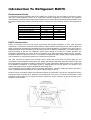
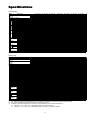
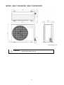
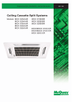
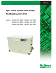
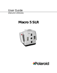
Your Climate. We're There. R407C Air Cooled Condensing Unit Models: M4LC M4LC M4LC M4LC M4LC M4LC M4LC 010B/BR 015B/BR 020B/BR 025B/BR 030C/CR 040C/CR 050C/CR IMPORTANT This air conditioners use new refrigerant R407C. Please refer to “Special Precautions” when dealing with refrigerant R407C unit. REGISTERED ISO 9002 TM: R407C – 2250A Contents Introduction To Refrigerant R407C .....................................................................................2 Specifications ......................................................................................................................3 Outlines And Dimensions ...............................................................................................4 - 5 Wiring Diagrams ............................................................................................................6 - 9 Special Precautions ...................................................................................................10 - 11 Installation ..................................................................................................................12 - 16 Servicing and Maintenance.........................................................................................17 - 18 Troubleshooting ..........................................................................................................19 - 24 Parts List.....................................................................................................................25 - 28 Note: Installation and maintenance are to be performed only by qualified personnel who are familiar with local codes and regulations, and experienced with this type of equipment. Caution: Sharp edges and coil surfaces are a potential injury hazard. Avoid contact with them. Warning: Moving machinery and electrical power hazards. May cause severe personal injury or death. Disconnect and lock off power before servicing equipment. "McQuay" is a registered trademark of McQuay International. All rights reserved throughout the world. 1999 McQuay International "Bulletin illustrations cover the general appearance of McQuay International products at the time of publication and we reserve the right to make changes in design and construction at any time without notice." 1 Introduction To Refrigerant R407C Environmental friendly The Montreal Protocol regulation calls for the phase-out of HCFCs by the year 2030 to prevent the ozone layer from further depletion. R407C is an environment friendly refrigerant to replace R22. The operating characteristics of R407C system bears close similarity to that of R22. R407C thermophysical properties such as pressure-temperature behavior, and heat-transfer characteristic are somewhat similar to the properties of R22. Physical Property Molecular Wt (g/mol) Vapor Density (kg/m3) Liquid Density (kg/m3) Boiling Point (°C) Latent Heat Vap (kJ/kg) Ozone Depletion Potential Global Warming Potential R407C 86.2 42.0 1134 -37.1 to -44.3 245 0.00 1600 R22 86.5 44.2 1195 -40.8 234 0.05 1700 R407C characteristics R407C is a ternary mixture of R32, R125, and R134a with weight composition of 23%, 25% and 52% respectively. These three components have different vapor pressure and boiling points. R407C liquid and vapor components have different compositions when the fluid evaporates or condenses. This gives rise to a temperature glide where the bubble point and dew point are of different temperatures. The effect of glide in heat exchangers is that as the refrigerant mixture flows through the tubing at constant pressure, the evaporating temperature will change as the composition of the liquid and vapor phases change. Typically, the glide for R407C is about 5°C to 10°C. The extend of temperature glide actually varies with the pressure and composition of components present in the mixture during the leak. The main concerns for R407C is its zeotropic nature. When leak occurs and only vapor leaks out, the composition of the refrigerant mixture left in the system will change. Especially, when the system is idle, R32 being the lightest component will leak out more than the other components. What remains in the system will be of different composition. If the leaked system is subsequently top-up with R407C, the mixture in the system will varies from the original composition percentage ratio. This composition shift will slightly affect the system performance. However, study has shown that after a series of repeated leaks and top-ups, the system capacity drops up to 6%. Another concern for R407C system is the lubricant used for its compressor. Like all HFC refrigerants, R407C uses polyol ester oil (POE) as its lubricant. This hydroscopic oil is prone to moisture contamination. Extra precaution must be taken not to expose the R407C system too long to moist air; as the oil will soak up the moisture into the system. 2 Specifications Cooling Only COIL FIN PIPE OUTDOOR UNIT TUBE FAN COMP MODEL OUTDOOR UNIT NOMINAL COOLING CAPACITY REFRIGERANT / CONTROL POWER SOURCE COMPRESSOR TYPE CAPACITOR RATED RUNNING CURRENT RATED INPUT POWER PROTECTION DEVICE FAN TYPE / DRIVE BLADE MATERIAL DIAMETER RATED RUNNING CURRENT RATED INPUT POWER MATERIAL DIAMETER THICKNESS MATERIAL THICKNESS ROW FIN PER INCH FACE AREA HEIGHT DIMENSION WIDTH DEPTH WEIGHT MATERIAL CASING THICKNESS FINISHING TYPE SIZE LIQUID GAS PACKING HEIGHT DIMENSION WIDTH DEPTH REFRIGERANT CHARGE kcal/h W Btu/h V/Ph/Hz µF A W mm/in A W mm/in mm/in mm/in m2/ft2 mm/in mm/in mm/in kg mm/in mm/in mm/in mm/in mm/in mm/in kg M4LC 010B 2,268 2,637 9,000 M4LC 015B M4LC 020B M4LC 025B M4LC 030C M4LC 040C M4LC 050C 2,772 4,612 5,292 7,560 9,576 12,600 3,223 5,363 6,155 8,792 11,134 14,650 11,000 18,300 21,000 30,000 38,000 50,000 R407C / CAPILLARY TUBE (OUTDOOR) R407C / CAPILLARY TUBE (OUTDOOR) + (TXV) 240 / 1 / 50 415 / 3 / 50 ROTARY HERMATIC SCROLL 30 30 45 50 50 4.00 6.20 9.91 12.50 11.40 6.30 8.20 900 1,350 2,112 2,660 2,560 3,741 4,328 OVERLOAD PROTECTION PROPELLER / DIRECT GLASS REINFORCED ACRLY STYRENE RESIN 335 / 14 406 / 16 610 / 24 0.28 0.56 1.09 62 133 241 SEAMLESS COPPER 9.52 / 3/8 0.36 / 0.014 ALUMINIUM (SLIT FIN TYPE) 0.127 / 0.005 1 2 2 1 19 14 16 16 0.32 / 3.50 0.51 / 5.53 0.87 / 9.33 494 / 19.4 646 / 25.4 850 / 33.5 740 / 29.1 840 / 33.1 1,030 / 40.6 270 / 10.6 330 / 13.0 400 / 15.7 31.0 34.0 57.0 58.0 92.5 98.9 115 GALVANIZED MILD STEEL 1.0 ~ 2.3 (0.0393 - 0.0905) 0.8 / 0.031 EPOXY POLYESTER POWDER FLARE VALVE / AEROQUIP FLARE VALVE 6.35 / 1/4 6.35 / 1/4 6.35 / 1/4 9.52 / 3/8 9.52 / 3/8 9.52 / 3/8 9.52 / 3/8 9.52 / 3/8 12.70 / 1/2 15.88 / 5/8 15.88 / 5/8 15.88 / 5/8 19.05 / 3/4 19.05 / 3/4 1,000 / 39.4 558 / 22.0 710 / 28.0 851 / 33.5 957 / 37.7 1,200 / 47.2 560 / 22.0 401 / 15.8 461 / 18.1 0.78 0.93 1.65 1.65 1.90 3.13 3.15 Heat pump 1) 2) 3) TUBE FIN COIL PIPE OUTDOOR UNIT FAN COMP MODEL OUTDOOR UNIT NOMINAL COOLING CAPACITY NOMINAL HEATING CAPACITY REFRIGERANT / CONTROL POWER SOURCE COMPRESSOR TYPE CAPACITOR RATED RUNNING CURRENT (COOLING) RATED RUNNING CURRENT (HEATING) RATED INPUT POWER (COOLING) RATED INPUT POWER (HEATING) PROTECTION DEVICE FAN TYPE / DRIVE BLADE MATERIAL DIAMETER RATED RUNNING CURRENT RATED INPUT POWER MATERIAL DIAMETER THICKNESS MATERIAL THICKNESS ROW FIN PER INCH FACE AREA HEIGHT DIMENSION WIDTH DEPTH WEIGHT MATERIAL CASING THICKNESS FINISHING TYPE SIZE LIQUID GAS PACKING HEIGHT DIMENSION WIDTH DEPTH REFRIGERANT CHARGE kcal/h W Btu/h kcal/h W Btu/h V/Ph/Hz µF A A W W mm/in A W mm/in mm/in mm/in 2 2 m /ft mm/in mm/in mm/in kg mm/in mm/in mm/in mm/in mm/in mm/in kg M4LC 010BR 2,268 2,637 9,000 2,394 2,784 9,500 M4LC 015BR M4LC 020BR M4LC 025BR M4LC 030CR M4LC 040CR M4LC 050CR 2,772 4,536 5,170 7,310 9,830 12,100 3,223 5,274 6,008 8,499 11,430 14,068 11,000 18,000 20,500 29,000 39,000 48,000 3,150 4,790 6,050 7,812 10,332 12,600 3,663 5,569 7,034 9,083 12,013 14,654 12,500 19,000 24,000 31,000 41,000 50,000 R407C / CAPILLARY TUBE (OUTDOOR) R407C / CAPILLARY TUBE (OUTDOOR) + (TXV) 240 / 1 / 50 415 / 3 / 50 ROTARY HERMATIC SCROLL 30 30 45 50 50 NIL NIL 4.00 6.20 9.50 12.60 11.50 6.20 8.80 3.30 5.70 10.10 12.50 11.40 5.90 7.80 900 1,350 2,002 2,571 2,424 3,565 4,615 750 1,200 2,096 2,549 2,407 3,280 3,734 OVERLOAD PROTECTION PROPELLER / DIRECT GLASS REINFORCED ACRLY STYRENE RESIN 335 / 14 406 / 16 610 / 24 0.28 0.56 1.09 62 133 241 SEAMLESS COPPER 9.52 / 3/8 0.36 / 0.014 ALUMINIUM (SLIT FIN TYPE) 0.127 / 0.005 1 2 2 19 14 16 0.32 / 3.50 0.51 / 5.53 0.77 / 8.29 0.56 / 6.00 494 / 19.4 646 / 25.4 960 / 37.80 772 / 30.40 740 / 29.1 840 / 33.1 1,095 / 43.10 991 / 39.00 270 / 10.6 330 / 13.0 437 / 17.20 400 / 15.75 31.0 34.0 57.0 58.0 92.5 98.9 115.0 GALVANIZED MILD STEEL 0.8 / 0.031 1.0 - 2.3 ( 0.0393 - 0.0905 ) EPOXY POLYESTER POWDER FLARE VALVE / AEROQUIP FLARE VALVE 6.35 / 1/4 6.35 / 1/4 6.35 / 1/4 9.52 / 3/8 9.52 / 3/8 9.52 / 3/8 9.52 / 3/8 9.52 / 3/8 12.70 / 1/2 15.88 / 5/8 15.88 / 5/8 15.88 / 5/8 19.05 / 3/4 19.05 / 3/4 558 / 22.0 710 / 28.0 1,016 / 40.0 851 / 33.5 957 / 37.7 1,207 / 47.5 401 / 15.8 461 / 18.1 559 / 22.0 0.98 1.00 1.70 1.65 2.35 3.10 3.35 ALL SPECIFICATIONS ARE SUBJECTED TO CHANGE BY THE MANUFACTURER WITHOUT PRIOR NOTICE. ALL UNITS ARE BEING TESTED AND COMPLY TO ARI 210/240-89. NOMINAL COOLING AND HEATING CAPACITY ARE BASED ON THE CONDITIONS BELOW : a) COOLING – 26.7°C DB / 19.4°C WB INDOOR AND 35°C DB OUTDOOR. b) HEATING – 21.1°C DB / 15.6°C WB INDOOR AND 8.3°C DB / 6.1°C WB OUTDOOR. 3 Outlines And Dimensions Model : M4LC 010B/015B, 010BR/015BR All dimensions in mm Model : M4LC 030/040/050C, M4LC 030/040/050CR All dimensions in mm 4 MODEL : M4LC 030/040/050C, M4LC 030/040/050CR All dimensions in mm Caution Sharp edges and coil surfaces may cause injury. Wear protective gloves when handling the unit. 5 Wiring Diagrams Model : M4LC 010B/015B Model : M4LC 010BR/015BR 6 Model : M4LC 020B/025B Model : M4LC 020BR/025BR 7 Model : M4LC 030C Model : M4LC 030CR 8 Model : M4LC 040C/050C Model : M4LC 040CR/050CR 9 Special precautions when dealing with refrigerant R407C unit 1) What is new refrigerant R407C? R407C is a zeotropic refrigerant mixture which has zero ozone depletion potential and thus conformed to the Montreal Protocol regulation. It requires Polyol ester oil (POE) oil for its compressor's lubricant. Its refrigerant capacity and performance are about the same as the refrigerant R22. 2) Components Mixture weight composition R32(23%), R125(25%), R134a(52%) 3) Characteristic • R407C liquid and vapor components have different compositions when the fluid evaporates or condenses. Hence, when leak occurs and only vapor leaks out, the composition of the refrigerant mixture left in the system will change and subsequently affect the system performance. If just additional refrigerant is added to leaked system, system performance will dop. It is recommended that the system should be evacuated thoroughly before recharging with R407C. • When refrigerant R407C is used, the composition will differ depending on whether it is in gaseous or liquid phase. Hence when charging R407C, ensure that only liquid is being withdrawn from the cylinder or can. This is to make certain that only original composition of R407C is being charged into the system. • POE oil is used as lubricant for R407C compressor, which is different from the mineral oil used for R22 compressor. Extra precaution must be taken not to expose the R407C system too long to moist air. 4) Check list before installation/servicing • Tubing Refrigerant R407C is more easily affected by dust of moisture compared with R22, make sure to temporarily cover the ends of the tubing prior to installation • Compressor oil No additional charge of compressor oil is permitted. • Refrigerant No other refrigerant other that R407C • Tools Tools specifically for R407C only (must not be used for R22 or other refrigerant) i) Manifold gauge and charging hose ii) Gas leak detector iii) Refrigerant cylinder/charging cylinder iv) Vacuum pump c/w adapter v) Flare tools vi) Refrigerant recovery machine 5) Handling and installation guidelines Like R22 system, the handling and installation of R407C system are closely similar. All precautionary measures; such as ensuring no moisture, no dirt or chips in the system, clean brazing using nitrogen, and thorough leak check and vacuuming are equally important requirements. However, due to zeotropic nature of R407C and its hydroscopic POE oil, additional precautions must be taken to ensure optimum and trouble-free system operation. a) Filter-dryer must be installed along the liquid line for all R407C air conditioners. This is to minimise the contamination of moisture and dirt in the refrigerant system. Filter-dryer must be of molecular sieve type. For a heat-pump system, install a two-way flow filter dryer along the liquid line. b) During installation or servicing, avoid prolong exposure of the internal part of the refrigerant system to moist air. Residual POE oil in the piping and components can absorb moisture from the air. 10 c) Ensure that the compressor is not expose to open air for more than the recommended time specified by its manufacturer (typically less than 10 minutes). Removed the seal-plugs only when the compressor is about to be brazed. d) The system should be thoroughly vacuumed to 1.0 Pa (-700mmHg) or lower. This vacuuming level is more stringent than R22 system so as to ensure no incompressible gas and moisture in the system. e) When charging R407C, ensure that only liquid is being withdrawn from the cylinder or can. This is to ensure that only the original composition of R407C is being delivered into the system. The liquid composition can be different from the vapor composition. R32/R125/R134 33% / 33% / 34% 23% / 25% / 52% Composition of R407C in vapor phase is different from liquid phase. f) Normally, the R407C cylinder or can is being equipped with a dip-pipe for liquid withdrawal. However, if the dip-pipe is not available, invert the cylinder or can so as to withdraw liquid from the valve at the bottom. Invert cylinder without dip-pipe Dip-pipe Liquid withdrawal g) When servicing leak, the top-up method, commonly practiced for R22 system, is not recommended for R407C system. Unlike R22 where the refrigerant is of a single component, the composition of R407C, which made-up of three different components, may have changed during the leak. Consequently, a top-up may not ensure that the R407C in the system is of original composition. This composition shift may adversely affect the system performance. It is recommended that the system should be evacuated thoroughly before recharging with R407C. 11 Installation Caution Sharp edges and coil surface are potential injury hazard. Avoid from contact with them. (1) Installation of indoor unit For installation of indoor unit, please refer to the indoor unit technical manual. (2) Installation of outdoor unit As condensing temperature rises, evaporating temperature rises and cooling capacity drops. In order to achieve maximum cooling capacity, the location selected for outdoor unit should fulfill the following requirements :• Install the condensing (outdoor) unit in a way such that hot air distributed by the outdoor condensing unit cannot be drawn in again (as in the case of short circuit of hot discharge air). Allow sufficient space for maintenance around the unit. • Ensure that there is no obstruction of air flow into or out of the unit. Remove obstacles that block air intake or discharge. • The location must be well ventilated, so that the unit can draw in and distribute plenty of air thus lowering the condensing temperature. • A place capable of bearing the weight of the outdoor unit and isolating noise and vibration. • A place protected from direct sunlight. Otherwise use an awning for protection, if necessary. • The location must not be susceptible to dust or oil mist. 12 Installation clearance • Outdoor units must be installed such that there is no short circuit of the hot discharge air or obstruction to smooth air flow. Select the coolest possible place where intake air should not be hotter than the outside temperature (max. 45°C) A B C D Series I Minimum Distance 150 mm 1,000 mm 150 mm 500 mm Series II 300 mm 1,000 mm 300 mm 500 mm (3) Refrigerant piping Caution Must install a molecular-sieve type filter dryer along the liquid line. Maximum pipe length and maximum number of bends • When the pipe length becomes too long, both the capacity and reliability drop. As the number of bends increases, system piping resistance to the refrigerant flow increases. This will lower the cooling capacity and as a result, the compressor may become defective. Always choose the shortest path and follow the recommendation as tabulated below : MODELS DATA Max. Length (m) Max. Elevation (m) Max. No of Bends 10 15 20 25 30 40 50 7 5 10 10 5 10 15 8 10 15 8 10 20 10 10 20 10 10 20 10 10 Piping sizes (flare connection type) • Piping sizes are as follows : MODELS Liquid (mm/in) Suction (mm/in) 10 15 20 25 30 40 50 6.35 (1/4) 9.52 (3/8) 6.35 (1/4) 12.70 (1/2) 6.35 (1/4) 15.88 (5/8) 9.52 (3/8) 15.88 (5/8) 9.52 (3/8) 15.88 (5/8) 9.52 (3/8) 19.05 (3/4) 9.52 (3/8) 19.05 (3/4) PIPING CONNECTION TO THE UNITS • Align the centre of the piping and sufficiently tighten the flare nut with fingers. • Finally, tighten the flare nut with torque wrench until the wrench clicks. • When tightening the flare nut with torque wrench, ensure the direction for tightening follows the arrow on the wrench. PIPE SIZE (mm/in) 6.35 (1/4) 9.52 (3/8) 12.70 (1/2) 15.88 (5/8) 19.05 (3/4) TORQUE (Nm) 18 42 55 65 78 13 (4) Wiring Electrical connections • Wiring regulations on wire diameters differ from country to country. Please refer to your LOCAL ELECTRICAL CODES for field wiring rules. Be sure that installation comply with such rules and regulations. General precautions • Ensure that the rated voltage of the unit corresponds to the name plate before carrying out proper wiring according to the wiring diagram. • Provide a power outlet to be used exclusively for each unit. A power supply disconnect and a circuit breaker for over-current protection should be provided in the exclusive line. • The unit must be GROUNDED to prevent possible hazards due to insulation failures. • All wiring must be firmly connected. • All wiring must not touch the hot refrigerant piping, compressor or any moving parts of fan motors. (5) Vacuuming and charging • The pre-charged outdoor unit does not need any vacuuming or charging. However once it is connected, the connecting pipe line and the indoor need to be vacuumed before releasing R407C from the outdoor unit. 1) Open the service port core cap. 2) Connect pressure gauge to the service port. 3) Connect the line to vacuum pump. Open the charging manifold valve and turn the pump on. Vacuum to -0. 1 MPa (-760mmHg) or lower. Evacuation time varies by the capacity of the pump but average time is approximately 1 hour. Diagram 1 4) After evacuation, unscrew the spindle (Diagram 2B) for the gas to run to indoor unit. Diagram 2 14 Caution R407C must be charged as liquid. Usually R407C cylinder is equipped with a dip-pipe for liquid withdrawal. If there is no dip-pipe, the cylinder should be inverted so as to withdraw liquid R407C from the valve. Caution Do not top-up when servicing leak, as this will reduce the unit performance. Vacuum the unit thoroughly and then charge the unit with fresh R407C according to the amount recommended in the specification. (6) Additional charge • The refrigerant gas has already been pre-charged into the outdoor unit. For the piping length of 5m and below, additional refrigerant charge after vacuuming is not necessary. • When the piping length is more than 5m, please use the table below (unit in grams). MODEL 10 15 20 25 30 40 50 7m 40 40 40 80 90 90 90 10m 100 100 100 200 225 225 225 15 15m 200 200 200 400 450 450 450 20m 675 675 675 Caution Avoid prolong exposure of an opened compressor, or the internal part of refrigerant piping to moist air. The POE oil in the compressor and piping can absorb moisture from air. (7) Overall checking • Ensure the following, in particular : 1) The unit is mounted solidly and rigid in position. 2) Piping and connections are leak proof after charging. 3) Proper wiring has been done. • Drainage check - pour some water into drain pan. • Test run 1) Conduct a test run after water drainage test and gas leakage test. 2) Watch out for the following : a) Is the electric plug firmly inserted into the socket? b) Is there any abnormal sound from unit? c) Is there any abnormal vibrations with regard to unit itself or piping? d) Is there smooth drainage of water? • Check that : 1) Condenser fan is running, with warm air blowing off the condensing unit. 2) Evaporator blower is running and discharge cool air. 3) Suction (low side) pressure as recommended. 4) The remote controller incorporate a 3 minute delay in the circuit. Thus, it requires about 3 minutes before the condensing unit can start up. (8) Standard operating condition COOLING ONLY UNIT Temperature Minimum indoor temperature Maximum indoor temperature Minimum outdoor temperature Maximum outdoor temperature Ts °C 19.4 26.7 19.4 46.0 Th °C 13.9 19.4 13.9 24.0 Ts °C 10.0 26.7 -8.0 24.0 Th °C -9.0 18.0 HEAT PUMP UNIT Temperature Minimum indoor temperature Maximum indoor temperature Minimum outdoor temperature Maximum outdoor temperature Ts : Dry bulb temperature Th : Wet bulb temperature 16 Servicing And Maintenance Caution Disconnect from Main Supply before Servicing the air conditioner The unit is designed to give a long life operation with minimum maintenance required. However, it should be regularly checked and the following items should be given due attention. Components Air Filters (Indoor unit) Maintenance Procedure 1. Clean with a vacuum cleaner, or by tapping lightly on any hard surface and then washing in lukewarm water (below 40°C) With neutral soap. Recommended Schedule Every 2 weeks. More frequently if required. 2. Rinse well to dry before re-installing. 3. Note : Never use petrol, thinner, benzene or any other chemicals. Indoor Unit 1. Clean away dirt or dust on grille or panel by wiping with a soft cloth soaked in lukewarm (or cold) water or neutral detergent solution. Every 2 weeks. More frequently if required. 2. Note: Never use petrol, thinner, benzene or any other volatile chemicals, which may cause plastic surface to deform. Condensate Drain 1. Check and clean. Every 3 months. 2. Check for unusual noise. As necessary. Pan & Pipe Indoor Fan Indoor/Outdoor Coil 1. Check and remove dirt which are clogged between fins. 2. Check and remove obstacles which hinder air flow in and out of indoor/outdoor unit. Electrical Every month. Every month. 1. Check voltage, current and wiring. Every 2 months. 2. Check faulty contacts caused by loose connections, foreign matters, etc. Every 2 months. Compressor 1. No maintenance needed if refrigerant circuit remains sealed. However, check for refrigerant leak at joints & fittings. Every 6 months. Compressor Lubrication 1. Oil is factory charged. Not necessary to add oil if circuit remains sealed. No maintenance required. Fan Motors Lubrication 1. All motors pre-lubricated and sealed at factory. No maintenance required. 17 Pre-start up maintenance (after extended shutdown) - Inspect thoroughly and clean indoor and outdoor units. Clean or replace air filters. Clean condensate drain line. Clean clogged indoor and outdoor coils. Check fan imbalance before operation. Tighten all wiring connections and panels. Check for refrigerant leakage The design of the outdoor series allows servicing to be carried out readily and easily. The removal of the top side, front and back panel make almost every part accessible. CAUTION! Do not charge OXYGEN, ACETYLENE OR OTHER FLAMMABLE and poisonous gases into the unit when performing a leakage test or an airtight test. These gases could cause severe explosion and damage if expose to high temperature and pressure. It is recommended that only nitrogen or refrigerant be charged when performing the leakage or airtight test. 18 Troubleshooting When any air-conditioner malfunction is noted, immediately switch off the power supply to the unit, and contact the local dealer, if necessary. Some simple troubleshooting tips are given below : Fault Cause 1. Fan does not work 3 minutes • Protection against the frequent starting. Wait 3 or 4 minutes. after starting 2. The air conditioning unit does not • work • • • Power failure or you must be replaced the fuse. The power plug is disconnected. Possibility of making a programming error in the controller. If the fault persist after these verifications, contact your installer. 3. The air conditioning unit does not • blow sufficiently • • • The air filter is dirty. The doors or windows are open. The air entrance and exit are clogged. The regulate temperature is not high enough. 4. The remote deficient control light is • The batteries are discharge. • The batteries are not correctly inserted. • The assembly is not good. 5. Air discharge flow has a bad • This odor can be caused by cigarette smoke particles, perfume, odor sweat, which stick to the coil. • Check if there is any moisture on the walls, garment, other. • Check the drain pan. 6. Condensation on the air grille of • This is due to air humidity after a long time of operation. indoor unit • The unit has a lower temperature point, increase the point and operate at high speed. 7. The water flow of air conditioning • Check the condensate evacuation. unit 8. The air conditioning unit are • <<Air flow noise>> : refrigerant fluid admission in evaporator. noisy 19 For cooling only models or heat pump models (cooling cycle) Diagnosis by flow chart The following chart are efficient checking procedures for troubleshooting when these fan-coil units, are coupled with the condensing units using standard wiring. For dual circuited models, perform the procedures for each circuit. No Cooling : Check : Faulty : Cause Remedy No Cooling ( Compressor Does Not Start ) Evaporator Fan Motor Stop Unit Power Supply Running Faulty Fuse For Operation Circuit Blown Overcurrent Relay For Evaporator Fan Tripped Evaporator Fan Contactor No Voltage or Low Voltage Get the Right Voltage Single-Phase Repair the Power Line Components Shorted Connections Loose High Volage or Low Voltage Single-Phase Faulty Coil Burnt Contact Faulty Faulty Fan Motor Defective Operation Switch Condenser Fan Motor Repair or Replace The Components Tighten The Connections Get The Right Voltage Check The Power Supply To The Motor : Repair When Necessary Change The Contactor Repair The Contacts Repair Or Change The Motor Repair Or Replace The Switch Stop Overcurrent Relay For Condenser Fan Tripped High Voltage or Low Voltage Single-Phase Get The Right Voltage Check The Power Supply To The Motor : Repair When Necessary Running Condenser Fan Contactor Faulty Coil Burnt Contact Faulty Fan Motor Faulty Other Electrical Component Faulty Compressor Contactor Faulty Coil Burnt Contact Faulty Open Compressor Windings Incorrect Wiring 20 Change The Contactor Change The Contacts Repair or Change The Motor Repair or Change If Necessary Change The Contactor Repair The Contacts Change The Compressor Correct The Wiring Insufficient Cooling Insufficient Cooling Compressor Cycling Cycling On Dual Pressure Switch Tripping High Discharge Pressure or Low Suction Pressure Clogged Capillary or Pressure Switch Switch Faulty Running Overcurrent Relay For Compressor Tripping High Voltage or Low Voltage Single-Phase High Discharge Pressure And High Suction Pressure Loose Connections Discharge Gas Thermostat or Internal Thermostat Tripping High Discharge Pressure And Low Suction Pressure Refrigerant Short Charge or Refrigerant Leakage High Suction Pressure High Discharge Pressure or Low Suction Pressure See "High Discharge Pressure" or "Low Suction Pressure" Repair Clogging and Replace The Switch If Required Repair or Change If Necessary Get The Right Voltage Check The Power Line To The Compressor : Repair When Necessary See "High Discharge Pressure" or "High Suction Pressure" Tighten The Connections See "High Discharge Pressure" or "Low Suction Pressure" Add Refrigerant. Repair Leakage If Detected. See "High Suction Pressure" See "High Discharge Pressure" or "Low Suction Pressure" High Discharge Pressure High Discharge Pressure Restricted Condenser Air Flow Clogged Condenser Coil Low Fan Speed Condenser Air Inlet Temperature High Malfunction Of Fan Cycling System Circulating Air Flow Overcharged Refrigerant Non-Condensable Gas Restricted Liquid Line High Suction Pressure Clean The Condenser Check The Voltage And Get The Right Voltage Check The System And Repair If Required Secure Space For Required Air Flow Purge The Refrigerant Purge The Gas Remove The Restriction See "High Suction Pressure" Low Discharge Pressure Low Discharge Pressure Condenser Air Flow Excessive Malfunction Of Fan Cycling System Low Refrigerant Charge Low Ambient Temperature 21 Check The System And Repair The Components If Required Add Refrigerant See The Unit Working Range High Suction Pressure High Suction Pressure Low Evaporator Air Inlet Temperature Excessive Fresh Air Intake Reduce The Fresh Air Intake Insufficient Duct Insulation Reinforce The Duct Insulation Defective Compressor Valve Overcharged Refrigerant Change Or Repair The Compressor Purge The Refrigerant Low Suction Pressure Low Suction Pressure Evaporator Air Flow Restricted Evaporator Air Inlet Temperature Clogged Air Filter Low Clean The Air Filter Restricted Duct Remove The Restriction Low Fan Speed Adjust The Fan Speed Short Cycling Faulty Thermostat Restricted Liquid LIne And Suction Line Remove Obstacles To Air Circulation Repair Or Replace If Necessary Remove The Restriction Low Refrigerant Charge Add Refrigerant Low Discharge Pressure See "Low Discharge Pressure" Noisy Operation Noisy Operation Compressor Noisy Shipping Bolt(s) Noisy Unremoved Shipping Bolt(s) Overcharged Refrigerant Liquid Refrigerant Backing Up Low Suction Pressure Worn Compressor Parts Evaporator Fan Liquid Line Noisy Knocking Runner Noisy Strainer Whistling Worn Bearing Remove The Bolt(s) Purge The Refrigerant See "Low Suction Pressure" Replace Or Repair The Compressor Fix The Runner Or Casing Properly Change The Bearing Partially Clogged Clean The Dryer Refrigerant Short Charge Add Refrigerant Loose Fixed Screws Inadequate Duct Work 22 Tighten All Fixed Screws Check Flexible Ducts For Heat Pump Models By means of pressure readings : Pressure Probable Cause High Side Low Side 1. 2. 3. 4. = = High Side Low Side High Side Low Side Too High A Little High Normal Circuit A Little Low Too Low Data 1. Poor compression/no compression (compressor defective.) 2. Check valve stick in open position. 3. Reversing valve leaking. 1. Undercharged with refrigerant. 2. Refrigerant leakage. 3. Air filter clogged/dirty (indoor unit). 4. Indoor fan locked.(cooling) 5. Defective defrost control, outdoor coil freezed up (heating). 6. Outdoor fan locked (heating). 1. Outdoor fan blocked (cooling). 2. Outdoor coil dirty (cooling). 3. Indoor fan locked (heating). 4. Indoor filter clogged/dirty (heating). 5. Non-condensable gases in refrigerant circuit (e.g. air) 1. Air intake temperature of indoor unit too high. = = = = = High Side Low Side = = High Side Low Side Overcharged with refrigerant. Non-condensable gases in refrigerant circuit (e.g. oil). Obstructed air-intake/discharge. Short circuiting of hot air outdoor unit. = By means of diagnosis flow chart Generally, there are two kinds of problems, i.e. starting failure and insufficient cooling/heating. "Starting Failure" is caused by electrical defect while "Insufficient Cooling/Heating" is caused by improper application or defects in refrigerant circuit. i) Diagnosis of Electric Circuit No Cooling / Heating Unit fail to start Check power supply - voltage - phase - frequency Check settings of remote control box Check power source cord Check circuit breaker & fuse Fan fails to start Compressor fails to start Fan Motor Capacitor defective Loose Connections, Contactors Irregular motor resistance (Ω) & insulation (M Ω) Thermostat setting too high Protection Device Actuated Voltage supply not within range Loose Connections, Improper wiring Compressor Capacitor Defective Reset Check motor resistance (Ω ) and insulation (MΩ) Replace Fan Motor Regular but fails to start Irregular Compressor locked (to replace compressor) Compressor Motor damaged ( to replace compressor) 23 The most common causes of air conditioner failure to “start" are:a) Voltage not within ±10% of rated voltage. b) Power supply interrupted. c) Control settings improper. d) Air conditioner is disconnected from main power source. e) Fuse blown or circuit breaker off. II) Diagnosis of refrigerant circuit / application There might be some cases where the unit starts running but does not perform satisfactory, i.e. insufficient cooling. Judgment could be made by measuring temperature difference of indoor unit's intake and discharge air as well as running current. Insufficient Cooling Unit Starts Check air circulation High cooling load Refrigerant circuit Indoor/Outdoor coil dirty (clogged) Air filters dirty Fan Malfunction Leakage Excessive heat source e.g. electric kettle Restriction e.g. at strainer, capillary, filter dryer, etc. Room overcrowded with people Compressor Windows / doors wide open Obstruction at air inlet/outlet of indoor/outdoor unit Less or no compression (Low running current) Satisfactory operation with temperature difference of air intake & discharge of indoor unit 8°C - 13°C Insufficient Heating Unit Starts Check air circulation High heating load Refrigerant circuit Indoor/Outdoor coil dirty (clogged) Leakage Air filters dirty Restriction e.g. at strainer, capillary, filter dryer, etc. Fan Malfunction Compressor Obstruction at air inlet/outlet of indoor/outdoor unit Less or no compression (Low running current) Satisfactory operation with temperature difference of air intake & discharge of indoor unit 14°C - 20°C 24 Windows / doors wide open Parts List Model : M4LC 010B/015B/020B/025B 1. BACK PANEL 16. ROTARY COMPRESSOR 2. TOP PANEL 17. RUBBER GROMMET 3. CONDENSER COIL ASSY. 18. COMPRESSOR NUT 4. FAN MOTOR BRACKET 19. BASE PAN ASSY. 5. FAN MOTOR 20. CAPILLARY TUBE ASSY. 6. FLINGER 21. PARTITION 7. RING WASHER 22. TERMINAL BOX PANEL ASSY. 8. FAN BLADE 23. SIDE PANEL 9. SQUARE WASHER 24. ACCESS PANEL 10. HEX NUT 25. FLARE VALVE MOUNTING PLATE 11. BLACK LABEL 26. SUCTION VALVE (5/8”) 12. FRONT PANEL 27. LIQUID VALVE 13. OUTER NOZZLE 14. SUCTION PIPE ASSY. 15. DISCHARGE PIPE ASSY. 25 Model : M4LC 010BR/015BR/020BR/025BR 1. BACK PANEL 16. ROTARY COMPRESSOR 2. TOP PANEL 17. RUBBER GROMMET 3. CONDENSER COIL ASSY. 18. COMPRESSOR NUT 4. FAN MOTOR BRACKET 19. BASE PAN ASSY. 5. FAN MOTOR 20. CAPILLARY TUBE ASSY. 6. FLINGER 21. PARTITION 7. RING WASHER 22. TERMINAL BOX PANEL ASSY. 8. FAN BLADE 23. SIDE PANEL 9. SQUARE WASHER 24. ACCESS PANEL 10. HEX NUT 25. FLARE VALVE MOUNTING PLATE 11. BLACK LABEL 26. SUCTION VALVE (5/8”) 12. FRONT PANEL 27. LIQUID VALVE 13. OUTER NOZZLE 28. DEFROST SENSOR AND CLIP 14. 4-WAY VALVE ASSY. 15. DISCHARGE PIPE ASSY. 26 Model : M4LC 030C/040C/050C 1. ASSY. BASE PAN 10. BACK RIGHT PANEL 2. SUCTION VALVE 11. TOP PANEL 3. LIQUID VALVE 12. CONDENSER COIL ASSY. 4. PARTITION PANEL 13. MOTOR BRACKET 5. CRANKCASE HEATER 14. SIDE LEFT PANEL 6. COMPRESSOR ASSY. 15. FAN MOTOR ASSY. 7. SERVICE PANEL 16. FAN BLADE 8. TERMINAL BOARD MAIN ASSY. 17. FRONT PANEL ASSY. 9. ACCUMULATOR 27 Model : M4LC 030CR/040CR/050CR 1. ASSY. BASE PAN 11. 4 WAY VALVE ASSY. 2. SUCTION VALVE 12. BACK RIGHT PANEL 3. LIQUID VALVE 13. DEFROST SENSOR AND CLIP 4. PARTITION PANEL 14. TOP PANEL 5. CRANKCASE HEATER 15. CONDENSER COIL ASSY. 6. COMPRESSOR ASSY. 16. MOTOR BRACKET 7. TXV ASSY. 17. SIDE LEFT PANEL 8. SERVICE PANEL 18. FAN MOTOR ASSY. 9. TERMINAL BOARD MAIN ASSY. 19. FAN BLADE 10. ACCUMULATOR 20. FRONT PANEL ASSY. 28 DOP: 042000 Americas - 13600 Industrial Park Boulevard, P.O. Box 1551, Minneapolis, MINI 55440 USA (612) 553-5330 Asia - Jalan Pengapit 15/19, P.O. Box 7072, 40702 Shah Alam, Selangor Darul Eshan, Malaysia - Tel: 6-03-55194922 - Fax: 6-03-55106980 - Telex: MA 38521 Europe - 42 Cours Jean Jaurès - 17800 Pons - France - Tél: (33) 46 92 33 33 - Télex: 790 536 F - Télecopie: (33) 46 91 38 33