1
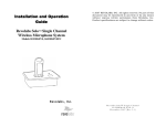
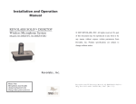
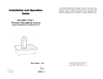
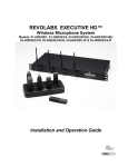
Installation and Operation Manual
SOLO – EXECUTIVE
Wireless Microphone System
(01-EXESYS and 03-EXESYSEU)
© 2006 REVOLABS, INC. All rights reserved.
No part of this document may be reproduced in
any form or by any means without express written
permission
from
Revolabs,
Inc.
Product
specifications are subject to change without
notice.
Solo – Executive Manual 01-EXEMAN-PAP-11 Mfg. #91-8562-30N00 August 2006 (Rev 2.2)
i
Table of Contents
Safety and General Information................................................ 2
FCC User Information ..................................................................... 2
European Compliance..................................................................... 3
Safety Compliance .......................................................................... 3
System Components ................................................................ 4
Solo Executive Charger Base................................................... 5
Power Module ................................................................................. 5
System Mute Switch........................................................................ 5
Solo Personal Microphone Modules ......................................... 5
Charging the Batteries .................................................................... 6
Using the Microphone ..................................................................... 6
Solo Executive Base Station .................................................... 7
Installation....................................................................................... 8
Connections .................................................................................... 8
Set-up ............................................................................................. 8
Pairing Wireless Microphones to Base Station ............................... 8
Pairing Charger Base to Base Station............................................. 9
System Mute Function Switch....................................................... 10
DB25 Control Port ......................................................................... 10
System Functions ......................................................................... 12
Indicator LEDs .............................................................................. 13
Warranty ................................................................................ 15
System Specifications ............................................................ 16
Safety and General Information
IMPORTANT INFORMATION ON SAFE AND EFFICIENT OPERATION. READ THIS
INFORMATION BEFORE USING YOUR DEVICE.
FCC User Information
FCC Registration Number: 0014898290
FCC ID Number: T5V01EXESYS
Solo Executive Base Station
FCC ID Number: T5V01EXEMIC
Solo Executive Microphone
FCC Notice to Users
Users are not permitted to make changes or modify the equipment in any way. Changes
or modifications not expressly approved by Revolabs, Inc. could void the user’s authority
to operate the equipment.
This device complies with Part 15 of the FCC Rules. Operation is subject to the following
two conditions: (1) this device may not cause harmful interference, and (2) this device
must accept any interference received, including interference that may cause undesired
operation.
IMPORTANT NOTE: Federal Communications Commission (FCC) Radiation Exposure
Statement – This equipment complies with FCC radiation exposure limits set forth for an
uncontrolled environment.
Professional Installation
This product must be professionally installed.
Industry Canada Notice to Users
Operation is subject to the following two conditions: (1) This device may not cause interference
and (2) This device must accept any interference, including interference that may cause
undesired operation of the device Ref IC: RSS 210 Sec. 5.11. The term “IC:” before the
certification/registration number only signifies that registration was performed based on a
Declaration of Conformity indicating that Industry Canada technical specifications were met. It
does not imply that Industry Canada approved the equipment. See Ref IC Self-Marking 6(f) and
RSP-100 Sec. 4.
IC ID Number: 6455A-01EXESYS
IC ID Number: 6455A-01EXEMIC
Solo Executive Base Station
Solo Executive Microphone
Restricted use with certain medical devices
Hearing Aids
Some devices may interfere with some hearing aids. In the event of such interference, you may
want to consult with your hearing aid manufacturer to discuss alternatives.
Other Medical Devices
If you use any other personal medical device, consult the manufacturer of your device to
determine if it is adequately shielded from RF energy. Your physician may be able to assist you in
obtaining this information.
2
Export Law Assurances
This product is controlled under the export regulations of the United States of America and
Canada. The Governments of the United States of America and Canada may restrict the
exportation or re-exportation of this product to certain destinations. For further information contact
the U.S. Department of Commerce or the Canadian Department of Foreign Affairs and
International Trade. The use of wireless devices and their accessories may be prohibited or
restricted in certain areas. Always obey the laws and regulations on the use of these products.
01-EXESYS North America UPCS Usage Restriction
Due to the UPCS frequencies used, this product is licensed for operation only in the United
States of America and Canada.
03-EXESYSEU European Union Usage Restriction
Due to the frequencies used, this product is licensed for operation only in the European Union
countries.
European Compliance
This equipment has been approved in accordance with Council Directive 1999/5/EC “Radio
Equipment and telecommunications Equipment.”
Conformity of the Equipment with the guidelines below is attested by the CE mark.
Model Numbers:
03-EXERACEU-BLK-11
03-EXEMICEU-BLK-11
03-EXECHGEU-BLK-11
Solo Executive Base Station
Solo Executive Microphone
Solo Executive Charger
Standards to which Conformity is declared:
ETSI EN 301 489-6 v1.2.1 (2002-04)
Title:
Electromagnetic compatibility and Radio spectrum matters (ERM); ElectroMagnetic Compatibility
(EMC) standard for radio equipment and services; Part 6: Specific conditions for Digital Enhanced
Cordless Telecommunications (DECT) equipment.
Safety Compliance
TUV Rheinland of North America, Inc.
3
Introduction
Congratulations on the purchase of a Revolabs digital wireless communication system! We are
pleased that you have chosen the Solo Executive Wireless Microphone System with 1.9 GHz
DECT technology. The Solo Executive provides high band-width audio from multiple wireless
microphones enabling reliable, un-tethered communications in audio and video conferences.
The Solo Executive Wireless Microphone System is a unique marriage of innovative technology
and ergonomic stylish design. The system uses Multi-Carrier, Time Division Multiple Access and
Time Division Duplex (MC/TDMA/TDD) radio transmissions both to and from the microphone.
This technology allows the microphones to co-exist with other wireless products such as wireless
LANs (802.11B&G), as well as allowing digital encryption technology to ensure secure
communications, and eliminates “buzzing” in the audio from cell phones.
System Components
Your Solo Executive System package contains a rackmountable Base Station, a Charger Base
and eight wireless microphones. The Base Station houses the processor and one end of the
wireless connection. It has two sets of diversity antennas and provides individual line-level audio
in and out for each microphone channel. This allows for additional post processing by external
multi-channel equipment. The Charger Base unit stores and charges the wireless microphones
when not in use. There are many features that this system provides that increase the productivity
of a conference call including consistent audio input from all participants, decreased room noise,
auto and manual mute, wireless encryption, re-synchronization and full duplex audio.
4
Solo Executive Charger Base
The Charger Base is used for storage and charging the microphone when not in use.
Microphones must be properly inserted into the base and seated flush for charging to occur.
4
1. System MUTE Switch — overrides individual Microphone
mute function.
2. LED indicator — power / mute status indicator.
3. Charger Bays — charges up to 8 Microphones.
4. Line Cord Receptacle — power supply input (on rear).
2
1
3
Power Module
The Charger Base requires 5VDC power. Plug the supplied AC adapter into an appropriate power
outlet 110-220 AC, 50-60Hz. The power LED on the Charger Base will illuminate.
System Mute Switch
There is a system MUTE button on the Charger Base. In normal operation the LED will be solid
GREEN (power on). In this mode, the microphone devices can individually mute themselves.
Pressing the system MUTE button will mute “all” wireless microphones in the system and the
Charger Base LED will turn RED. All microphones active in the system will also change to
flashing RED LED status indicating muted microphone audio. To un-mute all microphones, press
the system MUTE button again. The Charger Base LED will return to solid GREEN, and all
microphones will return to their previous state prior to the system mute.
Note: Pressing the MUTE button on a microphone while the system mute is active (solid RED
LED on Charger Base) will NOT un-mute the microphone.
Solo Personal Microphone Modules
The wireless personal microphone modules are synchronized to the rackmounted Base Station
and can be worn on the user’s shirt pocket, lapel or on a lanyard. They provide high quality full
duplex audio between each user and the conferencing phone/system. This system allows
attendees to step out of the conference room area and still participate in the call.
1. Mute Button — controls multiple microphone functions.
2. Charging Port — accepts the storage base battery charger.
3. LED Indicator — provides a visual status about wireless
module.
4. Earpiece Jack — accepts the 2.5mm plug for the earpiece.
5. Pocket Clip — attaches microphone to user.
5
1
4
5
3
2
Charging the Batteries
How to Charge
1. Place microphone(s) into the Executive Charger Base.
2. During charging, the LED indicator turns on (RED) and remains on until charging completes.
The microphones are muted while in the Charger Base. In normal use, batteries should fully
charge in about 2 hours, and can be “quick-charged” to 80% capacity in 45 minutes.
3. When charging completes, the LED turns off and the microphone is ready for use.
Note: A fully charged module battery provides approximately 8 hours of talk time.
When to Charge
First-time use — before using the wireless microphones the first time, charge the self-contained
battery for eight hours (or overnight) in the Charger Base.
Recharging — when the yellow light starts to flash on the microphone the battery needs
recharging. Over time (years), batteries gradually wear down and require longer charging times.
This is normal.
The Lithium Polymer rechargeable batteries that power the microphones are not user
serviceable. Please contact your AV service provider for replacement instructions and to assure
the proper disposal method is used. Warning: Never dispose of batteries in a fire because
they may explode.
Using the Microphone
1. Remove the microphone from the Charger Base. The
microphones turn on and mute themselves automatically
when removed from Charger Base, to reduce noise while
being attached to clothing.
2. The wireless microphone has a clip on the back which allows
the microphone to be easily clipped onto a shirt pocket,
blouse or lapel. The microphone can also be clipped on to a
lanyard and be worn around the neck. Attach the microphone
to clothing or to a lanyard, as close to the mouth as possible
(within 6 - 12 inches is recommended).
3. With the microphone in the wearing position, un-mute the microphone by pressing and
releasing the MUTE button (confirm by viewing flashing GREEN LED).
4. To turn microphones off, return the microphone unit to the Charger Base or press and hold the
MUTE button for ~10 seconds until the LED turns solid RED and release button.
5. If the microphones are moved out of range of the Base Station (~30 meters) the connection will
be dropped (LED flashes all colors) and the microphone will mute. After 15 seconds the
microphone will beep 5 times, and will continue beeping every 30 seconds to remind the user
to return the microphone to the conference room. When the microphone is moved back into
range the connection will automatically be re-established to its original state, and the beeping
will cease.
6
Adjusting the Volume
The volume of the microphone is set at the factory and cannot be adjusted on the wireless
microphone. Access to each channel is provided on the Base Station for external amplification.
Note: Moving the wireless microphone closer to the mouth will
increase the volume.
To change the volume on the earpiece, use the dial on the earpiece
wire. Turning the dial towards the earpiece will increase the volume,
and turning the dial towards the microphone will decrease the volume.
Use the attached clothing clip to secure the earpiece wire.
Solo Executive Base Station
4
1
2
5
3
6
7
9
8
11 12
13
14
10
1. Channel LED indicators: Displays
microphone and pairing states
8. Mini-Phoenix Connectors: Audio in and out
connections (8 channels in, 8 channels out)
9. Pairing LEARN Button and Signal LED: For
pairing Charger Mute to Base Station
2. Diversity Antennae: Two sets
3. Pairing Push Buttons: For pairing
microphones to Base Station
10. Local/remote selector switch
4. Muting Antenna
11. USB and Ethernet Ports (Future use)
5. Power On LED
12. Mini-Phoenix Connectors: Multi-base
station (BUS) synchronization connector
6. On/Off Switch: Powers up unit
13. System Mute function switch
7. Power In Connector (AC In)
14. DB25 Control Port (Parallel IO Port)
7
Installation
The Executive Base Station is easily installed into a standard 19” AV rack system using the
supplied rack ears and standard rack screws. The equipment requires 110-220V AC, 50-60 Hz,
power. Plug the power cord into an appropriate outlet and turn the circuit breaker-protected power
switch on the back panel to Reset. The GREEN power LED on the front panel will illuminate.
Attach the four diversity antennas (two on each side) and the system mute antenna (SMA male
connector) in the center.
Connections
There are eight mini-phoenix input and output ports on the back panel of the unit providing
access to each channel’s audio signal. The provided mini-phoenix connectors are designed for
easy wiring. The three terminals (from left to right) correspond to positive +, negative −, and
ground
. Use the screws on top of the connector to first loosen the terminal to insert an
appropriate 3 conductor cable (3 separate conductors, or 2 conductors and shield), and then
tighten the screw to secure. Push the connector onto the pins centered under the desired input or
output port until firmly secured.
There are eight output channels representing a separate channel for each microphone. Likewise,
there are eight input channels to the unit. The microphone output connectors need to be attached
to the line-level input connectors of an audio mixer. The Base Station input connectors should
then be attached to mixer channel outputs. Because the system is full-duplex, the input
connections provide the ability to hear program audio using the provided earpiece attached to the
microphone. Depending on the application, it is possible to feed a single mixed channel back to
all earpieces or, alternatively, each user can receive a separate and unique channel. This would
allow for translation or other services to be incorporated into an application.
Set-up
The Base Station has eight indicator LEDs (one for each channel) and pairing push buttons on
the front panel. When the LED is flashing GREEN or RED, that channel is active and connected
to a wireless microphone (GREEN is for live audio, RED is for muted). When the LED is off, the
channel is inactive (the microphone is out of range or turned off).
The front panel also has two sets of diversity antennae for best reception, and a fifth antenna for
system mute reception. These antennae are removable for relocation by installation
professionals, based on the installation environment and coverage optimization requirements.
Pairing Wireless Microphones to Base Station
“Pairing” creates a link between the wireless microphone and the Base Station with a unique
electronic serial number. When the microphone and Base Station have been previously paired,
the microphone will automatically try to connect to the Base Station whenever it is lifted from the
Charger Base.
Remember, microphones are always muted (flashing RED LED) when they are removed
from the Charger Base and the MUTE button needs to be pressed to make it “live” (flashing
GREEN LED).
Microphones in new systems come paired to the Base Station with each microphone assigned to
a unique channel on the base unit. However, if a replacement microphone is ever required, it will
need to be manually “paired.”
8
If a microphone is lifted from the Charger Base and the LEDs continuously flash alternating RED
and GREEN, and/or the Base Station LED flashes alternating RED and GREEN, the microphone
needs to be paired to the system. Make sure that all other microphones are properly paired, and
that the Base Station is powered on, before proceeding to pair an individual microphone. By
noting which microphone channels are already in use (paired), it will be obvious which channel to
use for pairing the microphone.
Microphone Pairing Instructions
1. First make sure the microphone is turned OFF (no LED activity). If the unit is ON, press and
hold the MUTE button for 10 seconds until the LED turns solid RED (do not release when you
hear two beeps). Release the button to turn the unit off.
2. Next, place the microphone unit into pairing mode by holding the MUTE button down for seven
seconds. The LED will turn solid GREEN and then solid RED. Release the MUTE button. The
microphone unit is now in pairing mode.
3. Within one minute, push and hold the button for the desired channel on the Base Station for
seven seconds to enter into pairing mode. The LED for that channel will be solid RED until
pairing starts, as indicated by Solid RED followed by a quick GREEN flash, then switching to
flashing RED on both the microphone and the Base Station (muted audio). Pairing is now
complete.
Pairing Charger Base to Base Station
“Pairing” is also used to create a link between the Charger Base system MUTE control and the
Base Station. When the Charger Base and Base Station are paired, the system mute function
may be used.
The Charger Base in new systems come paired to the Base Station. However, if a replacement
Charger Base is ever required, it will need to be manually “paired.”
System Mute Button Pairing Instructions
1. First, power-on the Charger Base and Base Station (power LEDs on both units are GREEN).
2. Next, place the Base Station system into pairing mode by briefly pressing the LEARN button on
the rear connection panel. The pairing LED next to the LEARN button will illuminate.
3. Now press the MUTE button on the Charger Base once. The pairing LED on the back of the
Base Station panel will go off and the power LED on the Charger Base will turn solid RED.
4. Press the MUTE button on the Charger Base again. The pairing LED on the Base Station will
flash twice and the power LED on the Charger Base will turn solid GREEN.
5. Once the pairing LED on the Base Station stops flashing, pairing is complete and the MUTE
button on the Charger Base will mute all the microphones in the system.
9
System Mute Function Switch
In certain circumstances it is preferable to use the muting capabilities in a DSP based automated
microphone mixer instead of the Charger Base system mute. This is the case when the mixer is
providing acoustic echo cancellation and needs a continuous signal to maintain a near-end audio
reference. The two position System Mute switch located on the back panel controls how the Base
Station handles the audio output for muted channels.
Position 1 (left side - default): Base Station completely shuts off audio out of each channel that is
in the mute state.
Position 2 (right side): Base Station leaves audio output of muted channel at the same level and
signals the appropriate “mute out” pin on DB25 connector for line muting on external hardware
(see DB25 below).
Warning: The Executive system will not mute when the switch is in Position 2 (right side).
Neither the microphone MUTE button, nor the System Mute button on the Charger Base will mute
audio. Muting is only controlled by the third party mixer.
DB25 Control Port
In connection with the System Mute switch, the DB25 Control Port allows the use of third party
control systems using parallel port IO (active low, open collector). The pin-out status functions
shown below can be used to provide system muting operations via third party products. The
System Mute switch should be pushed all the way to the right for this feature to operate. The
MUTE OUT indicators are used to determine muted channels and the SYS MUTE IN mutes all
channels by using a programmable muting macro in the control device.
DB25 Connector Pin
Function
Pin 1
Pin 2
Pin 3
Pin 5
Pin 7
Pin 9
Pin 11
Pin 13
Pin 15
Pin 25
Pin All Others
Mute – Channel 1 output
System Mute – Input
Mute – Channel 2 output
Mute – Channel 3 output
Mute – Channel 4 output
Mute – Channel 5 output
Mute – Channel 6 output
Mute – Channel 7 output
Mute – Channel 8 output
Ground
NA
Please see the operating manual for the third party control device for more information on setup
and programming.
10
Using Multiple Systems
If more than one Base Station is required for an area, each unit needs to be interconnected with a
sync cable using the supplied mini-phoenix connector. The three terminals correspond to positive
+, negative −, and ground
. Use the screws on top of the connector to first loosen the terminal to
insert an appropriate three conductor cable (3 conductors, or 2 conductors and shield), and then
tighten the screw to secure. Push the connector onto the pins labeled BUS. Each addition system
should be connected by paralleling the conductors through the phoenix terminals. For example,
there would be two conductors in each of the three terminals of the second Base Station in a
three Base Station system
One Station needs to be set as the LOCAL (Master) unit by sliding the switch next to the BUS port
to the left. The other units should remain in the REMOTE setting to the right (default position). The
LOCAL unit manages the entire system and distributes microphone transmission across the
available channels to maintain frequency integrity, and also coordinates system muting.
Note: The switch must be in the REMOTE position for a single Base Station system. Microphones
will not function if the switch is in the LOCAL position.
The maximum number of systems for a given area is three 01-EXESYS in North America (24
channels) and four 03-EXESYSEU for EU (32 channels).
11
System Functions
The following table shows the functions supported by the Solo Executive System:
Function
Base
Wireless
Station
Microphone
Status
Status
Enter Pairing Mode
On
Action
Off
Press the Microphone MUTE button for about 7 seconds (LED solid
RED), and then press the MUTE button on the Charger Base for
about 7 seconds (LED solid RED).
On
A short press of the Microphone MUTE button or Charger Base MUTE
button causes flashing RED LED on each unit indicating that the
Microphone has audio muted. Pressing either MUTE button again will
un-mute Microphone (flashing GREEN LED on each unit).
Mute
On
Turn Off Microphones
On
On
Press and hold the Microphone MUTE button for about 10 seconds,
until the LED stays solid RED, and then release.
Or
Dock the Microphone into the Charge Base for less than 2 seconds.
Turn On Microphones
Off
Off
Press and hold the Microphone MUTE button for about 3 seconds,
until the LED shows solid GREEN.
Or
Dock the Microphone into the Charge Base for at least 4 seconds.
12
Indicator LEDs
The following tables show activities associated with the various states shown by the LEDs:
Equipment Use
Microphone LED
Microphone in
Charger Base
Microphone not in
Charger Base
Solid RED
OFF
Base Station
Channel LEDs
OFF
OFF
OFF
OFF
Two RED flashes
every 1.5 seconds
GREEN flash every
1.5 seconds
Meaning
Charging in Progress
Charging Complete
Microphone powered
OFF or battery
discharged
RED Flashing
Microphone muted
GREEN Flashing
Microphone “live”
Pairing mode or
confirmation of
powering-down.
Microphone pairing
complete
Solid RED
Solid RED
RED / GREEN
Flashing
RED Flashing
Alternating slow
GREEN and RED
OFF
or Alternating slow
GREEN and RED
Microphone or
channel not paired
YELLOW flash
alternating with
GREEN or two RED
flashes
Solid GREEN
Microphone low
battery
Alternating RED,
YELLOW, GREEN,
YELLOW
OFF
Rapid RED flashes
continuing for more
than a few seconds
OFF
Groups of five rapid
RED flashes
OFF
Note: The Base Station power LED will be green when power is on.
13
Searching for a
connection, or out of
radio range. The
Microphone will try to
re-establish the link
for about 5 minutes,
and then turn off
automatically.
Radio congestion – it
is not possible to
make a radio
connection because
there are already too
many nearby users, or
there is heavy radio
interference.
Possibilities include
some types of digital
cordless phones, and
other Solo
installations.
Unit is faulty. Contact
your AV service
provider for advice.
Equipment Use
Microphone LED
Charger Base LED
Meaning
Microphone in
Charger Base
OFF
OFF
Charger Base is
unplugged
GREEN Flashing
Solid GREEN
RED Flashing
Solid RED
Equipment Use
Microphone
Earpiece
Microphone not in
Charger Base
Five rapid tones
repeated every 30
seconds
No audio or
deteriorating audio
quality
Five rapid tones
repeated every 20
seconds
Microphone not in
Charger Base
Microphone is “live”
Microphones muted
using Charger mute
Audio Indicators
14
Meaning
Microphone out of
range
Low battery
Warranty
Revolabs, Inc. warrants this product to be free of manufacturing defects. Repair or replacement of
any defective part or unit (at the discretion of the Seller) will be free of charge for the period of
one year.
Any attempt by the user to alter the equipment, or equipment damaged by negligence, accident,
or Acts of God voids this warranty.
The Seller shall not be liable for any consequential damage resulting from the malfunction of this
product. Should the user experience unsatisfactory performance from this equipment, contact the
Seller to obtain instructions for return, or replacement, as deemed necessary.
This warranty is not transferable by the original end user.
Revolabs, Inc.
63 Great Road
Maynard, MA 01754
www.revolabs.com
15
System Specifications
Dimensions, (L, W, H) and Weight
Executive Base Station 16.9” (43.03 cm) x 8.0” (20.32 cm) x 1.7” (4.42 cm), 6.5 lbs (2.95 kg)
Charger Base
8.3” (21.1 cm) x 4.3” (10.9 cm) x 1.0” (2.56 cm), 1.0 lb (0.45 kg)
Wireless Microphones 0.9” (2.4 cm) x 0.8” (1.95 cm) x 2.6” (6.68 cm), 0.05 lb (0.01 kg)
Shipping Weight
12.0 lbs (5.45 kg)
Radio Frequency
01-EXESYS
03-EXESYSEU
Connectors
Base Station
Charger Base
Microphone
1.92 to 1.93 GHz (UPCS North America)
315 MHz (System Mute North America)
1.88 to 1.90 GHz (DECT EU)
433.92 MHz (System Mute EU)
Audio In/Out (8/8) - Phoenix (3.5mm) quick connect terminal blocks
Sync BUS In/Out - Phoenix (3.5mm) quick connect terminal block
Diversity Antennae - SMA Plug (50 ohm)
System Mute Antenna – SMA Jack (50 ohm)
Control Port - DB25 Socket
Ethernet - RJ45 (future use)
USB – Type A (future use)
DC power input port
Proprietary 4 pin microphone charge jacks
Proprietary 4 pin charge plugs
2.5mm mono audio (8 ohm)
Power Requirements
Executive Base Station 100-240V AC, 50-60 Hz, 5W (Universal Inputs)
Charger Base
5V DC, 2 Amps (switching power supply varies by country)
Range
100’ (30 meters) approx. (no obstructions)
Channels
01-EXESYS
03-EXESYSEU
8 per Solo Executive System
24 channels maximum (3 systems)
32 channels maximum (4 systems)
Battery
Lithium Polymer
8 hours approx. talk time
Charge Time
2 hours approx.
Audio Bandwidth
100-6800 Hz
Encryption
128-bit proprietary (per microphone channel)
Included Accessories 8 Earpiece with inline volume control, 8 Lanyard
Environmental Requirements
Temperature
5 to 100 F (5° to 40° C) operating
Humidity
20% to 85%
16