1
User Manual
This page intentionally left blank
Table Of Contents
Introduction..........................................................3
Welcome!...................................................................................................... 3
About the GRIP ...................................................................4
GRIP Key Features .................................................................................... 4
How to Use This Manual ...................................................5
Important Safety Instructions..........................7
Important Safety Instructions (English).......................7
Safety symbols used in this product......................................................... 7
Please follow these precautions when using this product:.................... 7
Instructions de Sécurité Importantes
(French) ................................................................................9
Symboles utilisés dans ce produit............................................................. 9
Veuillez suivre ces précautions lors de l’utilisation de
l’appareil: ...................................................................................................... 9
Lesen Sie bitte die folgende
Sicherheitshinweise (German)........................................11
Sicherheit Symbole verwendet in diesem Produkt................................. 11
Folgen Sie bitte diesen Vorkehrungen, wenn dieses
Produkt verwendet wird: ........................................................................... 11
CE Declaration Of Conformity ........................................13
FCC Compliance Statement .............................................13
Getting Started.....................................................15
Hooking Up the GRIP ........................................................15
Applications .........................................................................15
DJ Setup....................................................................................................... 16
Recording ..................................................................................................... 16
Live Performance (Club/Concert)........................................................... 16
Important Notes on Using the GRIP ..............................16
Rack-Mounting the GRIP ......................................................................... 16
Connecting Instruments Safely................................................................. 16
Maintaining Proper Levels......................................................................... 16
Stabilizing Your Turntable and CD Player.............................................. 17
A Tour of the Grip................................................19
Front Panel ..........................................................................19
POWER Button.......................................................................................... 19
INPUT Knob.............................................................................................. 19
Crossover (XOVER) Knob....................................................................... 19
XOVER OUT Button................................................................................ 20
SUB BASS LEVEL knob .......................................................................... 20
BASS DRIVE Knob .................................................................................. 20
GAIN REDUCTION LED Meter.......................................................... 21
BASS LEVEL Knob .................................................................................. 21
BASS LEVEL LED Meter........................................................................ 21
INPUT LEVEL LED Meter .................................................................... 19
CLIP LED Indicator.................................................................................. 19
1
Table Of Contents
LO CUT Knob ........................................................................................... 21
OUTPUT Knob ......................................................................................... 21
BYPASS Button .......................................................................................... 21
Rear Panel............................................................................22
INPUT Jacks ............................................................................................... 22
OUTPUT Jacks ........................................................................................... 22
XOVER OUTPUT Jack ............................................................................ 22
IEC POWER Jack ...................................................................................... 22
Suggested Settings ..............................................23
Troubleshooting...................................................25
Troubleshooting Index............................................................................... 25
Specifications .......................................................27
Audio Input ................................................................................................. 27
Audio Output .............................................................................................. 27
Audio Performance .................................................................................... 27
Mechanical ................................................................................................... 27
Index .......................................................................31
Warranty/Contact Alesis ....................................33
Alesis Limited Warranty............................................................................. 33
Alesis Contact Information....................................................................... 34
2
1 Introduction
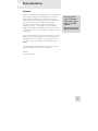
Welcome!
Thank you for making the Alesis GRIP a part of your setup. Since
1984, we've been designing and building creative tools for the
audio community. We believe in our products, because we've
heard the results that creative people like you have achieved with
them. One of Alesis' goals is to make high-quality studio
equipment available to everyone, and this User Manual is an
important part of that. After all, there's no point in making
equipment with all kinds of capabilities if no one explains how to
use them. So, we try to write our manuals as carefully as we build
our products.
For more effective
service and product
update notices, please
register your GRIP
online at:
http://www.alesis.com/
support/warranty.htm
The goal of this manual is to get you the information you need as
quickly as possible, with a minimum of hassle. We hope we've
achieved that. If not, please drop us an email and give us your
suggestions on how we could improve future editions of this
manual.
We hope your investment will bring you many years of creative
enjoyment and help you achieve your musical goals.
Sincerely,
The people of Alesis
3
1
Introduction
About the GRIP
The GRIP offers you advanced methods for processing and
generating low frequencies for live or recorded music. It
does this via two different methods of signal processing.
First, it gives you several different means of adjusting the
character and level of the low frequencies of the input
signal. Second, it includes a proprietary sub-harmonic
synthesizer that creates sub-bass signals harmonically related
to—but not present in—the original signal. In short, it
improves the bass that is there, and creates sub-bass where
none exists.
We created the GRIP so that it adjusts only the low
frequencies of an input signal so that you can improve the
bass without sacrificing the quality of the middle or upper
ranges. Furthermore, you have precise control over which
low frequencies are processed by the GRIP. This can add a
high-fidelity sound to any musical scenario: a DJ setup, a
club PA system, sound reinforcement at a concert and even
studio or home recording projects involving any sort of
instrument.
GRIP Key Features
4
1.
Digital signal processing with stereo input and stereo
output
2.
Simple front-panel interface that gives you quick and
easy access to all functions
3.
LO CUT control that protects speakers from damage
caused by ultra-low frequencies
4.
Proprietary digital sub-harmonic synthesis algorithm
adds bass not present in the original signal
5.
A crossover output that allows you to route the lowest
frequencies to a subwoofer
6.
LED meters that provide constant visual indication of
input level, gain reduction and bass level
Getting Started
1
How to Use This Manual
This manual is divided into the following sections
describing the various functions and applications for the
GRIP. While it's a good idea to read through the entire
manual once carefully, those having general knowledge
about studio equipment should use the table of contents to
look up specific functions.
Helpful tips and advice are
highlighted in a shaded box
like this.
Chapter 3: Getting Started. If you're already experienced with
signal processing, this will get you started using the GRIP
right away. It's a short guide to the essential elements of
hooking it up and using it for the first time. We’ve included
a hookup diagram plus some applications for which the
GRIP is most appropriate. The chapter ends with some
important notes on operating the unit.
Chapter 4: A Tour of the GRIP features diagrams of the front
and rear panels, along with descriptions of each of the
controls and features found there.
Chapter 5: Suggested Settings provides some suggested frontpanel settings for several usage scenarios.
Chapter 6: Troubleshooting can give you a hand if you’re
experiencing problems with the GRIP. You’ll find that most
issues can be resolved simply and quickly.
When something important
appears in the manual, an
exclamation mark (like the
one shown at left) will appear
with some explanatory text.
This symbol indicates that
this information is vital when
operating the GRIP.
Near the end of the manual are specifications, and an index
to help you find what you're looking for.
5
1
Introduction
This page intentionally left blank
6
2 Important Safety
Instructions
Important Safety Instructions (English)
Safety symbols used in this product
This symbol alerts the user that there are important
operating and maintenance instructions in the literature
accompanying this unit.
This symbol warns the user of un-insulated voltage
within the unit that can cause dangerous electric shocks.
This symbol warns the user that output connectors contain
voltages that can cause dangerous electrical shock.
Please follow these precautions when using
this product:
1. Read these instructions.
2. Keep these instructions.
3. Heed all warnings.
4. Follow all instructions.
5. Do not use this apparatus near water.
6. Clean only with a damp cloth. Do not spray any liquid
cleaner onto the faceplate, as this may damage the front
panel controls or cause a dangerous condition.
7. Install in accordance with the manufacturer's
instructions.
8. Do not install near any heat sources such as radiators,
heat registers, stoves, or other apparatus (including
amplifiers) that produce heat.
9. Do not defeat the safety purpose of the polarized or
grounding-type plug. A polarized plug has two blades
with one wider than the other. A grounding-type plug
has two blades and a third grounding prong. The wide
blade or the third prong is provided for your safety.
7
2
Important Safety Instructions
When the provided plug does not fit into your outlet,
consult an electrician for replacement of the obsolete
outlet.
10. Protect the power cord from being walked on or
pinched, particularly at plugs, convenience receptacles,
and the point where they exit from the apparatus.
11. Use only attachments or accessories specified by the
manufacturer.
12. Use only with a cart, stand, bracket, or table designed
for use with professional audio or music equipment. In
any installation, make sure that injury or damage will not
result from cables pulling on the apparatus and its
mounting. If a cart is used, use caution when moving
the cart/apparatus combination to avoid injury from tipover.
13. Unplug this apparatus during lightning storms or when
unused for long periods of time.
14. Refer all servicing to qualified service personnel.
Servicing is required when the apparatus has been
damaged in any way, such as when the power-supply
cord or plug is damaged, liquid has been spilled or
objects have fallen into the apparatus, the apparatus has
been exposed to rain or moisture, does not operate
normally, or has been dropped.
15. This unit produces heat when operated normally.
Operate in a well-ventilated area with at least six inches
of clearance from peripheral equipment.
16. This product, in combination with an amplifier and
headphones or speakers, may be capable of producing
sound levels that could cause permanent hearing loss.
Do not operate for a long period of time at a high
volume level or at a level that is uncomfortable. If you
experience any hearing loss or ringing in the ears, you
should consult an audiologist.
17. Do not expose the apparatus to dripping or splashing.
Do not place objects filled with liquids (flower vases,
soft drink cans, coffee cups) on the apparatus.
18. WARNING: To reduce the risk of fire or electric
shock, do not expose this apparatus to rain or moisture.
8
Important Safety Instructions
2
Instructions de Sécurité Importantes (French)
Symboles utilisés dans ce produit
Ce symbole alèrte l’utilisateur qu’il existe des
instructions de fonctionnement et de maintenance dans la
documentation jointe avec ce produit.
Ce symbole avertit l’utilisateur de la présence d’une
tension non isolée à l’intérieur de l’appareil pouvant
engendrer des chocs électriques.
Ce symbole prévient l'utilisateur de la présence de
tensions sur les raccordements de sorties, représentant un
risque d'électrocution.
Veuillez suivre ces précautions lors de
l’utilisation de l’appareil:
1. Lisez ces instructions.
2. Gardez ces instructions.
3. Tenez compte de tous les avertissements.
4. Suivez toutes les instructions.
5. N’utilisez pas cet allareil à proximité de l’eau.
6. Ne nettoyez qu’avec un chiffon humide. Il est
potentiellement dangereux d'utiliser des pulvérisateurs
ou nettoyants liquides sur cet appareil.
7. Installez selon les recommandations du constructeur.
8. Ne pas installer à proximilé de sources de chaleur
comme radiateurs, cuisinière ou autre appareils (don’t les
amplificateurs) produisant de la chaleur.
9. Ne pas enlever la prise de terre du cordon secteur. Une
prise murale avec terre deux broches et une troisièrme
reliée à la terre. Cette dernière est présente pour votre
9
2
Important Safety Instructions
sécurité. Si le cordon secteur ne rentre pas dans la prise
de courant, demandez à un électricien qualifié de
remplacer la prise.
10. Evitez de marcher sur le cordon secteur ou de le pincer,
en particulier au niveau de la prise, et aux endroits où il
sor de l’appareil.
11. N’utilisez que des accessoires spécifiés par le
constructeur.
12. N’utilisez qu’avec un stand, ou table conçus pour
l’utilisation d’audio professionnel ou instruments de
musique. Dans toute installation, veillez de ne rien
endommager à cause de câbles qui tirent sur des
appareils et leur support.
13. Débranchez l’appareil lors d’un orage ou lorsqu’il n’est
pas utilisé pendant longtemps.
14. Faites réparer par un personnel qualifié. Une réparation
est nécessaire lorsque l’appareil a été endommagé de
quelque sorte que ce soit, par exemple losrque le cordon
secteur ou la prise sont endommagés, si du liquide a
coulé ou des objets se sont introduits dans l’appareil, si
celui-ci a été exposé à la pluie ou à l’humidité, ne
fonctionne pas normalement ou est tombé.
15. Puisque son fonctionement normale génère de la chaleur,
placez cet appareil au moins 15cm. des équipments
péripheriques et assurez que l’emplacement permet la
circulation de l’air.
16. Ce produit, utilisé avec un amplificateur et un casque ou
des enceintes, est capable de produite des niveaux
sonores pouvant engendrer une perte permanente de
l’ouïe. Ne l’utilisez pas pendant longtemps à un niveau
sonore élevé ou à un niveau non confortable. Si vous
remarquez une perte de l’ouïe ou un bourdonnement
dans les oreilles, consultez un spécialiste.
17. N'exposez pas l'appareil à l'égoutture ou à
l'éclaboussement. Ne placez pas les objets remplis de
liquides (vases à fleur, boîtes de boisson non alcoolique,
tasses de café) sur l'appareil.
18. AVERTISSEMENT: Pour réduire le risque du feu ou de
décharge électrique, n'exposez pas cet appareil à la pluie
ou à l'humidité.
10
Important Safety Instructions
2
Lesen Sie bitte die folgende Sicherheitshinweise (German)
Sicherheit Symbole verwendet in diesem
Produkt
Dieses Symbol alarmiert den Benutzer, daß es
wichtige Funktionieren und Wartung Anweisungen in der
Literatur gibt, die diese Maßeinheit begleitet.
Dieses Symbol warnt den Benutzer der nicht
isolierten Spannung innerhalb der Maßeinheit, die
gefährliche elektrische Schläge verursachen kann.
Dieses Symbol warnt den Benutzer, dem
Ausgabestecker Spannungen enthalten, die gefährlichen
elektrischen Schlag verursachen können.
Folgen Sie bitte diesen Vorkehrungen, wenn
dieses Produkt verwendet wird:
1. Lesen Sie die Hinweise.
2. Halten Sie sich an die Anleitung.
3. Beachten Sie alle Warnungen.
4. Beachten Sie alle Hinweise.
5. Bringen Sie das Gerät nie mit Wasser in Berührung.
6. Verwenden Sie zur Reinigung nur ein weiches Tuch.
Verwenden Sie keine flüssigen Reinigungsmittel. Dies
kann gefährliche Folgen haben.
7. Halten Sie sich beim Aufbau des Gerätes an die
Angaben des Herstellers.
8. Stellen Sie das Gerät nich in der Nähe von Heizkörpern,
Heizungsklappen oder anderen Wärmequellen
(einschließlich Verstärkern) auf.
11
2
Important Safety Instructions
9. Verfehlen Sie nicht den Zweck des grounging Terminals
auf dem Netzstecker. Dieses Terminal wird für Ihre
Sicherheit zur Verfügung gestellt.
10. Verlegen Sie das Netzkabel des Gerätes niemals so, daß
man darüber stolpern kann oder daß es gequetscht wird.
11. Benutzen Sie nur das vom Hersteller empfohlene
Zubehör.
12. Verwenden Sie ausschließlich Wagen, Ständer, oder
Tische, die speziell für professionelle Audio- und
Musikinstrumente geeignet sind. Achten Sie immer
darauf, daß die jeweiligen Geräte sicher installiert sind,
um Schäden und Verletzungen zu vermeiden. Wenn Sie
einen Rollwagen benutzen, achten Sie darauf, das dieser
nicht umkippt, um Verletzungen auszuschließen.
13. Ziehen Sie während eines Gewitters oder wenn Sie das
Gerät über einen längeren Zeitraum nicht benutzen den
Netzstecher aus der Steckdose.
14. Die Wartung sollte nur durch qualifiziertes Fachpersonal
erfolgen. Die Wartung wird notwendig, wenn das Gerät
beschädigt wurde oder aber das Stromkabel oder der
Stecker, Gegenstände oder Flüssigkeit in das Gerät
gelangt sind, das Gerät dem Regen oder Feuchtigkeit
ausgesetzt war und deshalb nicht mehr normal arbeitet
oder heruntergefallen ist.
15. Dieses Gerät produziert auch im normalen Betrieb
Wärme. Achten Sie deshalb auf ausreichende Lüftung
mit mindestens 15 cm Abstand von anderen Geräten.
16. Dieses Produkt kann in Verbindung mit einem
Verstärker und Kopfhörern oder Lautsprechern
Lautstärkepegel erzeugen, die anhaltende Gehörschäden
verursachen. Betreiben Sie es nicht über längere Zeit
mit hoher Lautstärke oder einem Pegel, der Ihnen
unangenehm is. Wenn Sie ein Nachlassen des Gehörs
oder ein Klingeln in den Ohren feststellen, sollten Sie
einen Ohrenarzt aufsuchen.
17. Setzen Sie den Apparat nicht Bratenfett oder dem
Spritzen aus. Plazieren Sie die Nachrichten, die mit
Flüssigkeiten (gefüllt werden Blumevases, Getränkdosen,
Kaffeetassen) nicht auf den Apparat.
18. WARNING: um die Gefahr des Feuers oder des
elektrischen Schlages zu verringern, setzen Sie diesen
Apparat nicht Regen oder Feuchtigkeit aus.
12
Important Safety Instructions
2
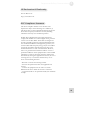
CE Declaration Of Conformity
See our Web site at:
http://www.alesis.com
FCC Compliance Statement
This device complies with Part 15 of the FCC rules.
Operation is subject to the following two conditions: (1)
This device may not cause harmful interference and (2) this
device must accept any interference received, including
interference that may cause undesired operation.
NOTE: This equipment has been tested and found to
comply with the limits for a Class B digital device, pursuant
to Part 15 of the FCC Rules. These limits are designed to
provide reasonable protection against harmful interference
in a residential installation. This equipment generates, uses
and can radiate radio frequency energy and, if not installed
and used in accordance with the instructions, may cause
harmful interference to radio communications. However,
there is no guarantee that interference will not occur in a
particular installation. If this equipment does cause harmful
interference to radio or television reception, which can be
determined by turning the equipment off and on, the user is
encouraged to try to correct the interference by one or
more of the following measures:
-- Reorient or relocate the receiving antenna.
-- Increase the separation between the equipment and
receiver.
-- Connect the equipment into an outlet on a circuit
different from that to which the receiver is connected.
-- Consult the dealer or an experienced radio/TV technician
for help.
13
2
Important Safety Instructions
This page intentionally left blank.
14
3 Getting Started
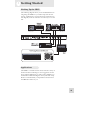
Hooking Up the GRIP
The following diagram shows you the standard method of
integrating the GRIP into your audio setup. See the next
section, “Applications,” for more about the connections in
this diagram, as well as some hints on other ways to use the
unit.
R
C
LI S
T ED
US
XXXXXXX
Applications
The GRIP is a versatile tool that can be used in a variety of
musical scenarios. Following are a few suggestions for the
most common applications, as well as some guidelines you
should follow when including the unit in your audio setup.
We also recommend that you experiment to find out how
the GRIP best works for you.
15
3
Getting Started
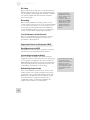
DJ Setup
When using the unit in a DJ setup, you should connect the
GRIP between the main outs of your mixer and the inputs
of your amplifier. The XOVER OUT should be connected
to a separate amplifier and subwoofer that can handle
very low frequencies.
Recording
When using the GRIP in a recording scenario, you can
connect the unit to the inserts on one or two mixer channels,
or to the mixer’s main inserts to cover the entire mix. You
can also plug an instrument directly into the GRIP and
connect the GRIP’s output to a mixer or recording device
such as a 4-track, ADAT or digital audio workstation.
Connecting the GRIP’s
XOVER OUT to a speaker
that can’t handle very low
frequencies could
permanently damage your
speakers if the SUB BASS
LEVEL setting is too high.
Always make sure you’re
outputting this signal to a
speaker system that can
handle it.
Live Performance (Club/Concert)
When using the GRIP for a live performance, connect it
between your mixer and amplifier in the same way as
described for a DJ setup above.
Important Notes on Using the GRIP
Rack-Mounting the GRIP
The GRIP fits in a 1U rack space. It’s perfectly normal for
the unit itself to get a little warm during operation.
Connecting Instruments Safely
When connecting the GRIP to instruments and other
equipment, always turn down the levels of the signals going
to your speakers or headphones. Also make sure that the
GRIP’s INPUT LEVEL knob is set fully counterclockwise.
These steps will prevent any unexpected, loud noises that
could damage your speakers (or your hearing).
Maintaining Proper Levels
Never use the GRIP at extreme levels, as this also could
damage speakers. Your speakers should be safe as long as
you keep the unit at a comfortable listening volume. The
GRIP creates incredible low-end even when the volume
isn’t at maximum. If you plan on using the unit at a
considerable volume, you will need an amplifier and
speakers built to handle very low frequencies.
16
It’s a good idea to turn off all
your equipment before
making connections. One of
the best ways to avoid
harmful transients is to turn
on your amplifier last, and
turn it off before all other
equipment.
Getting Started
3
Stabilizing Your Turntable and CD Player
Because a turntable is a delicate instrument, it is extremely
susceptible to audio vibrations that occur nearby, especially
low-frequency vibrations. The increased levels of bass
produced by the GRIP could cause your turntable to vibrate,
producing unwanted feedback. To avoid this problem, make
sure your turntable is a good distance away from your
speakers. You can take further precaution by installing shock
absorbers on your turntable. These can be found in stores
that sell DJ equipment.
CD players are also notorious for their susceptibility to lowfrequency rumble. To prevent your CD player from
skipping, make sure you place it far away from your speakers.
17
3
Getting Started
This page intentionally left blank.
18
4 A Tour of the GRIP
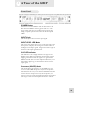
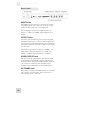
Front Panel
POWER Button
Press this to turn the GRIP on and off. The button is lit
blue when the GRIP is receiving power. This is a “soft”
power switch that does not actually interrupt power, but
simply suspends operation and turns off the front-panel
LEDs.
INPUT Knob
This knob adjusts the level of the input signal.
INPUT LEVEL LED Meter
This is the green meter that you see on the right side of the
front panel. It displays the average level of the louder of
the Right or Left input signals. It lights from left to right as
the level of the input signal increases.
CLIP LED Indicator
This indicator is the red light located to the right of the
INPUT meter. When lit it indicates that the input signal is
clipping, which means that the signal is too great for the
GRIP to handle. This can cause unpleasant distortion, so if
this indicator lights up, you should lower the level of the
input signal.
Crossover (XOVER) Knob
This knob adjusts the frequency of the GRIP’s two-way
crossover. The GRIP will process only those frequencies
that fall below the one you set with the XOVER knob. This
ensures that the unit processes only the frequencies you
want it to process, leaving the higher frequencies untouched.
The range of this control sweeps from 40 Hz to 160 Hz.
19
4
A Tour of the GRIP
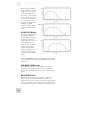
When using the GRIP on
program material – such as
a CD or LP - you should
set the XOVER knob to a
low setting so that the unit
doesn’t process the vocals
or other lead instruments.
For your reference, the
graphs at the right provide
examples of typical
frequency response curves
for bass, kick drums and
vocals.
XOVER OUT Button
This button toggles a highpass filter on the main
outputs. When you engage
the button, frequencies
falling below the setting of
the XOVER knob are
removed from the main
outputs (but are still
present in the XOVER
output). This allows you to
separately route the subbass present in the GRIP’s
signal.
When the XOVER button is not engaged, the main outputs
carry the GRIP’s total output signal, limited only by the LO
CUT knob.
SUB BASS LEVEL Knob
This controls output level of the GRIP’s sub-harmonic
synthesizer. This signal consists of the bass frequencies
produced by the GRIP that were not present in the original
signal.
BASS DRIVE Knob
This knob controls the action of a pair of multi-band
limiters acting on the Bass and Sub-Bass signals. You
should treat it as a tone control. Turning the knob clockwise
gives you a rounder sound with longer sustain, and turning
it counterclockwise gives you a faster, more dynamic sound.
20
A Tour of the GRIP
4
GAIN REDUCTION LED Meter
The red LED meter displays the amount of gain reduction
applied by the bass limiters. An increase in gain reduction –
by turning the BASS DRIVE Knob clockwise - will cause
the meter to light from right to left.
BASS LEVEL Knob
This knob adjusts the level of the frequencies that fall
below the crossover point set by the XOVER knob, except
for the sub-bass.
BASS LEVEL LED Meter
This meter indicates the level of the GRIP’s main output
signal. As you increase the level by turning the BASS
LEVEL knob clockwise, this meter lights amber from left
to right.
LO CUT Knob
This adjusts the cutoff frequency of a steep (6-pole) highpass filter, effectively limiting the lowest frequencies that the
GRIP can output. The unit will output only those
frequencies that are higher than the one set with the LO
CUT knob. This knob is useful for protecting your speakers
from ultra-low frequencies that may cause damage.
OUTPUT Knob
This knob controls the level of the GRIP’s total output
signal from both the bass and sub-bass channels.
BYPASS Button
When you activate this button, the audio signal bypasses the
Grip without being processed. This is useful when you want
to compare the processed signal with the unprocessed signal.
This button lights red when you enter BYPASS mode.
21
4
A Tour of the GRIP
Rear Panel
INPUT Jacks
The GRIP’s two input jacks give you analog stereo inputs
using TRS balanced 1/4” connectors. If you are using a
mono instrument, plug it into the left input jack.
The nominal input level, with the INPUT knob at 12
o’clock, is +4 dBu (1.23 VRMS). Input impedance is 10
kOhms.
OUTPUT Jacks
These two jacks provide analog stereo output using TRS
impedance-balanced 1/4” connectors. These outputs carry
the total signal from the GRIP, including the sub-harmonic
synthesizer’s channel. If you want to output a mono signal,
use either jack.
The nominal output level is +4 dBu (1.23 VRMS) = -15
dBFS, and the maximum output level is +19 dBu (6.9
VRMS) = -0 dBFS. Output impedance is 150 Ohms.
XOVER OUTPUT Jack
This jack carries the combined bass and sub-bass signals –
as determined by the XOVER Frequency and LO CUT
Frequency knobs.. This jack is a TRS impedance-balanced
1/4” connector, and has the same maximum output,
nominal output and impedance as the OUTPUT jacks.
IEC POWER Jack
Here’s where you plug in the GRIP’s IEC power cord. This
jack is made to accept most IEC power cords. It has a
universal input of 100 – 260 VAC.
22
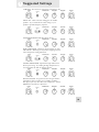
5 Suggested Settings
LARGE PA: Give those big sub-woofers something to do!
SMALL PA: A little extra bass embiggens the smallest
speakers. Try to match the LO CUT setting to your
speakers’ specified frequency response.
SYNTH BASS/BASS GUITAR: More is better.
BASS EXTENSION: Add clear, natural sub-bass to older
CDs and LPs. Mastering for vinyl meant stripping away the
lowest frequencies. Bring them back.
STUDIO CROSSOVER: Separate the highs and lows for
discreet processing. Try sending the high frequencies to a
reverb and then mix back in with the dry bass.
HEAVY GUITAR: You guitar not have enough “chunk”?
Tuned down and your strings are too flabby sounding?
Bass player quit? Try this! Most users will prefer to run the
GRIP before any effects or distortion.
23
This page intentionally left blank
24
6 Troubleshooting
Troubleshooting Index
Symptoms
Cause
Solution
Unit does not function (no
display or audio).
Unit not plugged in.
Make sure the power cord
is connected to the GRIP
and plugged into an
electrical outlet.
Audio distorted, even in
BYPASS.
Input level too high.
Reduce input level.
Output level too high.
Turn down master
volume.
Incorrect input/output
connections.
Refer to chapter 3.
Master volume set too low.
Change level setting.
Bass level or sub-bass level
set too low.
Change level settings.
LO CUT knob setting too
high.
Turn LO CUT knob
counterclockwise.
Not enough bass present
in input signal.
Adjust settings of input
instrument to see if more
bass can be input.
BYPASS button engaged.
Disengage the BYPASS
button.
XOVER OUT button
engaged.
Disengage XOVER OUT
button.
No sound, level low.
Bass not present or too
low.
Sub-bass signal not
present in main output.
25
This page intentionally left blank.
26
7 Specifications
Audio Input
Input Connectors:
Nominal Input Level
(Input Knob at 12:00):
Input Impedance:
Stereo balanced 1/4” TRS jacks
+4 dBu (1.23 VRMS)
10 kOhms
Audio Output
Output Connectors:
Nominal Output Level:
dBFS
Maximum Output Level:
dBFS
Output Impedance:
All measurements done with
INPUT knob turned fully
clockwise with a 1kHz sine
wave at -1.78 dBu (-1 dBFS)
input. Impedances are
measured at 1 kHz.
3 balanced 1/4” TRS jacks
+4 dBu (1.23 VRMS) = -1
+19 dBu (6.9 VRMS) = -0
150 Ohms
Audio Performance
Signal to Noise Ratio:
THD+N:
Frequency Response:
Power Consumption:
Hz)
> 108dB
< 0.0033%
20 Hz – 22 kHz ±1.0 dB
7 W max. (100-240 VAC/50-60
Mechanical
Size:
D
Rack Spaces:
Weight:
1.75” H x 19.0” W x 6.38” D
45mm H x 483mm W x 162mm
1 space
4 lbs (1.8 kg)
27
This page intentionally left blank.
28
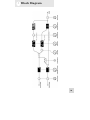
8 Block Diagram
29
Index
4-track, 16
ADAT, 16
amplifier, 16
BASS DRIVE knob, 20
BASS LEVEL knob, 20
BASS LEVEL meter, 20
BYPASS button, 21
CD player, 17
CLIP indicator, 20
connecting the GRIP, 16
controls
BASS LEVEL knob, 20
BASS-DRIVE knob, 20
BYPASS button, 21
INPUT knob, 19
LO CUT knob, 20
OUTPUT knob, 21
POWER button, 19
SUB-BASS LEVEL knob, 19
XOVER knob, 19
XOVER OUT button, 19
digital audio workstation (DAW), 16
DJ setup, 15
effect loop, 16
feedback, 17
front panel, 19
GAIN REDUCTION meter, 20
grounding, 7
high-pass filter, 20
hookup diagram, 15
IEC POWER jack, 22
INPUT jacks, 22
INPUT knob, 19
INPUT LEVEL meter, 20
levels
maintaining proper, 16
live performance, 16
LO CUT knob, 20
mixer, 15, 16, 22
OUTPUT knob, 21
outputs
main outputs, 22
XOVER OUT, 16
XOVER OUTPUT jack, 22
PA system, 16
POWER button, 19
Power cable, 8
R OUT button, 19
rack-mounting the GRIP, 16
rear panel, 22
recording, 16
RMS limiter, 20
safety instructions
English, 7
French, 9
German, 11
specifications, 27
SUB-BASS LEVEL knob, 19
subharmonic synthesizer, 4
subharmonic synthesizer, 22
transients, 16
troubleshooting, 25
turntable
stabilizing, 17
woofer, 15
XOVER knob, 19
XOVER OUT, 16
XOVER OUT button, 15
XOVER OUTPUT jack, 22
31
Warranty / Contact Alesis
Alesis Limited Warranty
ALESIS CORPORATION ("ALESIS") warrants this product to be free of defects
in material and workmanship for a period of one (1) year for parts and for a period of
one (1) year for labor from the date of original retail purchase. This warranty is
enforceable only by the original retail purchaser and cannot be transferred or assigned.
For the most effective service, the purchaser should register the purchase on the
ALESIS website at http://www.alesis.com/support/warranty.htm.
During the warranty period ALESIS shall, at its sole and absolute option, either repair
or replace free of charge any product that proves to be defective on inspection by
ALESIS or its authorized service representative. In all cases disputes concerning this
warranty shall be resolved as prescribed by law.
To obtain warranty service, the purchaser must first call or write ALESIS at the
address and telephone number available on the Alesis Website to obtain a Return
Authorization Number and instructions concerning where to return the unit for
service. All inquiries must be accompanied by a description of the problem. All
authorized returns must be sent to ALESIS or an authorized ALESIS repair facility
postage prepaid, insured and properly packaged. Proof of purchase must be
presented in the form of a bill of sale, canceled check or some other positive proof
that the product is within the warranty period. ALESIS reserves the right to update
any unit returned for repair. ALESIS reserves the right to change or improve design
of the product at any time without prior notice.
This warranty does not cover claims for damage due to abuse, neglect, alteration or
attempted repair by unauthorized personnel, and is limited to failures arising during
normal use that are due to defects in material or workmanship in the product.
THE ABOVE WARRANTIES ARE IN LIEU OF ANY OTHER
WARRANTIES OR REPRESENTATIONS WHETHER EXPRESS OR
IMPLIED OR OTHERWISE, WITH RESPECT TO THE PRODUCT, AND
SPECIFICALLY EXCLUDE ANY IMPLIED WARRANTIES OF FITNESS
FOR A PARTICULAR PURPOSE OR MERCHANTABILITY OR OTHER
IMPLIED WARRANTIES. Some states do not allow limitations on how long an
implied warranty lasts, so the above limitation may not apply to you.
IN NO EVENT WILL ALESIS BE LIABLE FOR INCIDENTAL,
CONSEQUENTIAL, INDIRECT OR OTHER DAMAGES RESULTING
FROM THE BREACH OF ANY EXPRESS OR IMPLIED WARRANTY,
INCLUDING, AMONG OTHER THINGS, DAMAGE TO PROPERTY,
DAMAGE BASED ON INCONVENIENCE OR ON LOSS OF USE OF THE
PRODUCT, AND, TO THE EXTENT PERMITTED BY LAW, DAMAGES
FOR PERSONAL INJURY. Some states do not allow the exclusion or limitation of
incidental or consequential damages, so the above limitation or exclusion may not
apply to you.
THIS CONTRACT SHALL BE GOVERNED BY THE INTERNAL LAWS OF
THE STATE OF CALIFORNIA WITHOUT REFERENCE TO CONFLICTS
OF LAWS. This warranty gives you specific legal rights, and you may also have other
rights required by law which vary from state to state.
This warranty only applies to products sold to purchasers in the United States of
America or Canada. The terms of this warranty and any obligations of Alesis under
this warranty shall apply only within the country of sale. Without limiting the
foregoing, repairs under this warranty shall be made only by a duly authorized Alesis
service representative in the country of sale. For warranty information in all other
countries please refer to your local distributor.
For more effective
service and product
update notices, please
register your GRIP
online at:
http://www.alesis.com/
support/warranty.htm
33