1
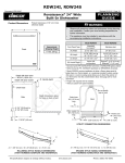
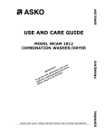
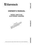
Installation Instructions
24 - Inch Built-in Dishwasher
Models: EDWH24S and IDWH24
Part No. 106842 Rev. C
Table of Contents
Important Safety Instructions.......................... 1
Important Information About Safety Instructions... 1
Safety Symbols and Labels............................. 1
General Safety Precautions............................. 2
Product Specifications..................................... 3
Product Dimensions......................................... 3
Planning the Installation................................... 4
Electrical Specifications................................... 4
Water Supply Specifications............................ 4
Preparing the Location..................................... 4
Preparing the Drain.......................................... 6
Installation Instructions.................................... 7
Verify the Package Contents............................ 7
Installation Preparation.................................... 8
Installing the Unit in the Cabinet.................... 10
Water Line Connection................................... 11
Verifying Operation......................................... 11
Final Leveling................................................. 12
Attaching the Anti-tip Brackets....................... 13
Installing the Toe Kick.................................... 13
Installation Checklist...................................... 14
Before You Begin...
Important:
Installer: In the interest of safety and to minimize problems, read these installation instructions completely and
carefully before you begin the installation process. Leave these installation instructions with the customer.
Customer: Keep these installation instructions for future reference and the local electrical inspector’s use.
Customer Service Information
If You Need Help...
Product Data Label Location
If you have questions or problems with installation,
contact your Dacor ® dealer or the Dacor Customer
Service Team. For repairs to Dacor appliances
under warranty call the Dacor Distinctive Service
line. Whenever you call, have the model and serial
number of the appliance ready. The model and serial
number are printed on the product data label.
The product data label is located on the right door
jamb. Open the door to expose it.
Dacor Distinctive Service
(repairs under warranty only)
Phone: (877) 337-3226 (U.S.A. and Canada)
Monday — Friday 6:00 a.m. to 4:00 p.m. Pacific Time
Dacor Customer Service
Phone: (800) 793-0093 (U.S.A. and Canada)
Monday — Friday 6:00 a.m. to 5:00 p.m. Pacific Time
Web site: www.Dacor.com
All specifications are subject to change without notice.
Dacor assumes no liability for changes to specifications.
© 2010 Dacor, all rights reserved.
II
Important Safety Instructions
Important Information About
Safety Instructions
•
•
The Important Safety Instructions and
warnings in these instructions are not meant
to cover all possible problems and conditions
that can occur. Use common sense and caution
when installing, maintaining or operating this or
any other appliance.
Always contact the Dacor Customer Service
Team about problems and conditions that you
don’t understand. See Customer Service
Information.
Safety Symbols and Labels
DANGER
Immediate hazards that WILL result in severe
personal injury or death.
warning
Hazards or unsafe practices that COULD result in
severe personal injury or death.
caution
Hazards or unsafe practices that COULD result in
minor personal injury or property damage.
DANGER
To avoid the possibility of explosion or fire, do not store or use combustible, flammable or explosive vapors
and liquids (such as gasoline) inside or in the vicinity of this or any other appliance. Do not store flammable
or explosive materials in adjacent cabinets or areas.
warning
A qualified technician must complete the installation of this built-in appliance. The owner is responsible to
make sure the dishwasher is properly installed. Improper connection of the electrical wiring may create an
electric shock or fire hazard and may result in damage to the dishwasher’s electrical system.
READ AND SAVE THESE INSTRUCTIONS
1
Important Safety Instructions
General Safety Precautions
WARNING - To reduce the risk of fire, electric shock, serious injury or death when using your appliance, follow
basic safety precautions, including the following:
Warning
Warning
• Use this dishwasher only for its intended
purpose as outlined in the use and care
manual. It is not intended for commercial use.
Read the use and care manual completely
before use.
• Do not tamper with the controls.
• Do not install or operate this dishwasher if it
has been damaged, dropped, has damaged
electrical wires or is not working properly. If
you receive a damaged product, immediately
contact your dealer or builder.
• Do not leave children alone or unattended in
the area where the dishwasher is in use.
• Keep all packaging materials away from
children. Plastic bags and sheets can cause
suffocation.
• To prevent child entrapment, always remove the
door from an old dishwasher when removing it
from service. Leave the racks in place. Cut the
prongs off of the power cord. Cut off the power
cord completely and discard.
• To avoid personal injury or property damage,
this dishwasher must be installed and grounded
in a completely enclosed cabinet according to
these installation instructions.
• All installation work, plumbing connections
and electrical wiring must be performed in
accordance with all applicable codes and
standards.
• Install or locate this appliance only in
accordance with these installation instructions.
• The installer must show the customer the
location of the electrical outlet or circuit breaker
panel so that the customer knows where and
how to disconnect power.
• Before installing or servicing the dishwasher,
disconnect the power plug from the electrical
outlet or turn off power at the circuit breaker.
• To prevent personal injury and damage to the
unit due to it tipping over, do not push down
on the door anytime it is open. To reduce the
chance of tipping, attach the anti-tip brackets to
the cabinet before use.
• The customer should not install, repair or
replace any part of the dishwasher unless
specifically recommended in the literature
accompanying it. A qualified service technician
should perform all other service. Contact the
nearest Dacor authorized service representative
for examination, repair or adjustment.
2
• This appliance is designed for installation by
more than one person. To avoid personal injury,
do not attempt to move or lift the dishwasher
without assistance.
• Use only detergents and rinse aids
recommended for use in a residential
dishwasher. Keep them out of the reach of
children.
• Never allow anyone, including children, to sit or
stand on any part of the dishwasher. Stepping
or sitting on any part of it may result in tipping,
damage and serious injury.
• If the dishwasher drain outlet is connected to
a garbage disposer, make sure the disposer
is completely empty before running the
dishwasher.
• Do not operate the dishwasher without the door
completely closed and all enclosure panels
properly in place.
• Many surfaces within the dishwasher can
achieve high temperatures. Do not touch interior
surfaces or items inside the dishwasher during
or immediately after use. Exercise caution when
opening the door. Let hot air and steam escape
before looking or reaching inside.
• During loading, insert all sharp or pointed
objects with the handles up. Locate these items
where they will not damage the door seal or
cause personal injury.
• To avoid damage to the racks, do not let sharp
edges come into contact with them.
• Under certain conditions hydrogen gas may be
produced in a hot water system that has not
been used for two weeks or more. Hydrogen
gas is explosive. If the hot water system has not
been used for a period of time, turn on all hot
water faucets and let the water flow for several
minutes to release any accumulated hydrogen
gas. Do not smoke or use an open flame during
this process.
• To prevent household mold and mildew
damage, periodically check the inlet and drain
hoses for leaks.
Product Specifications
Product Dimensions
Product tolerances: ±1/16” (±1.6 mm)
Style varies, model EDWH24S shown
Depth with door open
49 3/4” (126.4 cm)
Depth with door closed
C
A
D Handle depth
Drain hose
Depth dimensions allow
for hose on back of unit
Side
Front
B
5 1/4” (13.5 cm) to
7 1/4” (18.5 cm)
2” (50.0 cm)
Shipping weight: 108 lbs. (49 Kg)
Model
Description
A
B
C
Stainless steel
24”
34 3/8” (87.4 cm) to
EDWH24S
front panel
(61.0 cm) 36 1/2” (92.7 cm)
Integrated
3
front panel
IDWH24
22 7/8”
(58.1 cm)
23 1/2” 34 1/8” (86.7 cm) to
4
(59.7 cm) 36 1/8” (91.8 cm)
22 7/8”
5
(58.1 cm)
1
2
D
1
Epicure ®: 2 1/2” (6.4 cm)
2
Millennia ®: 2” (5.1 cm)
Varies with configuration
Epicure handle kit PN: ADWE24H
Millennia handle kit PN: ADWM24H
3
Do not modify
loop in hose
Drain hose
54" (137.0 cm)
long
Back
Model IDWH24 requires installation of a
customer provided, custom overlay door
panel. A custom overlay panel allows you to
blend the exterior of your dishwasher into
the overall kitchen décor. See page 6 for
more information.
4
Height with required trim kit installed.
5
Without custom front panel installed.
Power cord
44" (112.0 cm)
long
Water supply
line 60”
(152.0 cm) long
3 1/4" (8.3 cm)
2 3/4"
(7.0 cm)
Utility Connection Dimensions
3
Planning the Installation
warning
Observe all governing codes and ordinances during
planning and installation. Contact your local building
department for further information.
Electrical Specifications
warning
Electrical and grounding connections must comply
with the applicable portions of the national electrical
code and/or other local electrical codes.
The dishwasher comes with an electrical cord with
a three prong grounding plug
for 120 Vac, 15 Amp. supplied.
This cord should be plugged
only into a 120 Vac, three
prong, grounding electrical
outlet located to either side of
the dishwasher cutout.
If the cord is not long enough, or if a hard-wire
installation is needed, follow the instructions on
page 11.
Grounding Instructions for a
Permanently-Connected Appliance
This unit must be grounded to operate properly. It
must be connected to a grounded metal, permanent
wiring system, or an equipment-grounding conductor
must be run with the circuit conductors and
connected to the equipment-grounding terminal or
lead of the appliance. Damage to the dishwasher
could occur if it is not properly grounded.
A three conductor electrical cable or conduit meeting
local codes and ordinances is required. A UL listed
strain relief is required if non-metalic cable is used.
Suggested color coding: Black, white and green.
Circuit Requirements
The wiring from the electrical outlet or junction box
shall be connected to a circuit protected by a 15
Amp. circuit breaker or time delay fuse, installed by a
licensed electrician.
Water Supply Specifications
•
The dishwasher can be connected to a cold or
hot water supply (maximum 140°F, 60°C). Dacor
recommends using a hot water supply of 120°F
(49°C) to 140°F (60°C). If a cold water supply is
used, the washing times will be longer, but the
performance will not be affected.
•
The water supply pressure must be between 4.2
and 125 p.s.i. (30 - 862 kPa). The water supply
line and the shut-off valve must supply a flow
volume of at least 3 gallons (12 liters) per minute.
•
Install a 3/8” water supply valve for connection to
the dishwasher’s water supply line in a location
where it is easily accessible after the dishwasher
is installed.
•
The dishwasher water supply line is equipped
with a 3/8” (1.0 cm) NPT female compression
fitting on the end.
Electrical Requirements
Electrical Circuit
Requirements
15 Amp. 120 Vac, 60 Hz.
dedicated, grounded, circuit.
Total Connected Load 11 Amp. @ 120 Vac, 60 Hz.*
* For reference only. For exact specifications see the
product data label, located inside the right door jamb.
Grounding Instructions for a CordConnected Appliance
This appliance must be grounded. In the event of a
malfunction, grounding will reduce the risk of electric
shock by providing a path of least resistance for
electric current. This appliance is equipped with a
cord having an equipment-grounding conductor and
a grounding plug. The plug must be plugged into an
appropriate outlet that is installed and grounded in
accordance with all local codes and ordinances.
warning
•
Improper connection of the equipmentgrounding conductor can result in a risk
of electric shock. Check with a qualified
electrician or service representative if you are
in doubt whether the appliance is properly
grounded. Do not modify the plug provided with
the appliance, if it will not fit the outlet, have a
proper outlet installed by a qualified electrician.
•
Do not use an extension cord for this
appliance.
4
Planning the Installation
Preparing the Location
Cutout tolerances: +1/16” (+1.6 mm), -0
warning
Follow all cabinet dimensions shown to insure safe
operation. All minimum product dimensions must be
met or exceeded (see page 3). Dimensions
shown on the right provide the required clearances.
•
•
•
•
Drain line access
hole 2” x 2”
(5.1 cm x 5.1 cm)
Carefully check the location where the
dishwasher is to be installed. Put it in a location
with convenient access, close to the kitchen sink
for easy water supply and drain connection.
E
The electrical outlet or junction box must meet
the Electrical Specifications. The electrical
service must also be installed close by in a
cabinet adjacent to the location selected so that
the power cable can be disconnected without
removing the appliance from the cutout.
The opening through the partition between the
water supply valve/electrical service location and
the dishwasher cabinet cutout shall be located
near the floor and shall be large enough for
the water supply line and power plug to pass
through. The longest dimension of the opening
shall not be more than 1 1/2” (3.8 cm). If the
partition is wood, the edges of the opening shall
be smooth and rounded. If the partition is metal,
the edges of the opening shall be covered with
an edge protector. Call Dacor for the part number
of an approved edge protector.
The opening (E) through the partition between
the drain connection and the dishwasher cutout
must be higher than the disposer or waste tee
connection (see page 6) and lower than 30”
(76.0 cm). If the partition is wood, the edges of
the opening shall be smooth and rounded. If the
partition is metal, the edges of the opening shall
be covered with an edge protector.
Power cable/water
supply access hole(s)
1 ½” x 1 ½” max.
(3.8 cm x 3.8 cm)
F
23 5/8”
(60.0 cm)
24” (61.0 cm)
Dishwasher Cutout - Front View
Model
(F)**
EDWH24S
34 1/2” (87.6 cm) to 36 1/2” (92.7 cm)
IDWH24*
34 1/8” (86.7 cm) to 36 1/8” (91.8 cm)
*Model IDWH24 requires installation of a trim kit
(Dacor PN 106925) to fill the space between the edge
of the cutout and the dishwasher.
** If the height of the existing cutout is too low:
•
Check to see if the cabinet face can be trimmed
at the top. In many cases, when a non-standard
size dishwasher has been installed previously,
there is enough room inside the cabinet once the
cabinet face is modified.
•
Plan the installation so that the appliance can be
removed easily if service is required.
•
•
If the dishwasher is
installed in a corner,
there must be a
minimum clearance of
2” (5.1 cm) from the
side wall so the door
can open.
The dishwasher can be shortened 1/4” (6.0 mm)
by not installing the plastic feet on the unit as
shown on page 9. Extra care must be taken if the
feet are not installed. Dacor is not responsible for
floor damage during installation.
•
The dishwasher can be shortened 1/4” (6.0 mm)
by removing the trim pieces that surround the
wash compartment opening. NOTE: Doing so will
create a gap of 1/4” (6.0 mm) on the right and left
side of the door.
•
The floor must be
solid, level and all
cutout surfaces must
2”2”
(5.1(5.1
cm) Min.cm) min.
clearance
be at right angles. In
clearance
the interest of safety,
the surrounding cabinet must have sufficient
material for attachment of the anti-tip brackets
(see page 14).
5
Planning the Installation
Custom Door Panel/Handle for
Model IDWH24
•
•
The custom panel mounting screws are provided
with the dishwasher. Follow the template included
with the dishwasher to ensure that the panel and
the accompanying fasteners will fit properly.
The handle and handle mounting hardware
are not included with model IDWH24. A handle
designed for use with an appliance should
produce satisfactory results. Do not use a knob
or handle attached by a single fastener. Instead
use a handle with a larger D-style pull. The panel
craftsman must determine and obtain the proper
handle fasteners for the application. Handle
screw heads must be countersunk into the panel
before panel installation.
Preparing the Drain
CAUTION
Keep the factory installed high loop drain hose in
place to ensure proper dishwasher operation. Do
not modify or move the mounting bracket in any
manner. If it is necessary to lengthen the hose,
install an aftermarket drain extension kit, available
at most home improvement stores.
See facing page for drain installation examples.
IMPORTANT: Should a drain hose longer than the
one provided be required, use a hose extension
approved for detergents and high temperature water.
The drain hose supplied with the dishwasher meets
an AHAM DW-1 test standard. Total drain hose length
(including factory installed hose) must not exceed
14 ft. 9 in. (450.0 cm) from the top of the drain loop
on the back of the unit. Joints and joint tubes must
have a minimum inside diameter of 5/8” (1.6 cm).
•
The drain hose supplied with the dishwasher
must be connected to a minimum 1/2” inside
diameter drain connection.
•
The drain hose is
equipped with a coneshaped connector on
the end that is ready to
be cut to the desired drain connection size. Only
a clamp (not provided) is required. It fits drain
connections with an internal diameter of 1/2, 5/8,
23/32 and 7/8 inches (1.3, 1.6, 1.8 and 2.2 cm).
•
* Based on 24” (61.0 cm) wide cutout. Recommended
panel width is 1/4” (6.4 mm) less than cutout width.
You must install an air gap in the drain system
if required by local codes. Plan for the air
gap in the sink or countertop area adjacent to
the dishwasher. A section of drain hose (not
provided) needs to be installed from the air gap
to the waste disposer inlet or waste tee.
•
IMPORTANT: If the door panel weighs more than 15
pounds, you must order the optional heavy duty door
spring kit (Dacor PN 701385). Maximum panel weight
with heavy duty springs: 23 pounds.
If an air gap is not required, the drain hose must
be installed to a disposer inlet or waste tee above
the drain trap in the household plumbing.
•
The drain connection must be a minimum of 20”
(50.8 cm) above the floor.
•
No part of the drain hose can be lower than the
disposer or waste tee connection or higher than
37 1/2” (95.0 cm) above the floor.
G
H
J
Overall Custom Panel Specifications
for Model IDWH24
6
(G) Height
(H) Width
(J) Thickness
30 1/8”
(76.5 cm)
23 3/4”*
(60.3 cm)
3/4”
(1.9 cm) min.
Planning the Installation
Disposer connection
Disposer
connection
Air gap
Keep higher
than disposer
connection
Keep higher
than disposer
connection
20” min.
Sink trap
20” min.
Sink trap
Floor
Floor
Disposer Installation without Air Gap
Disposer Installation with Air Gap
Waste tee
Waste tee
Air gap
Keep higher
than tee
connection
Keep higher
than tee
connection
20” min.
Sink trap
Floor
Waste Tee Installation without Air Gap
Sink trap
20” min.
Floor
Waste Tee Installation with Air Gap
7
Installation Instructions
Verify the Package Contents
•
•
Remove all styrofoam and plastic wrap from the
dishwasher. Be sure to remove the toe kick from
the top of the dishwasher packaging. With the
assistance of at least one person, remove the
dishwasher from the shipping pallet. Place the
unit to the side of the cabinet opening.
A
Remove the “O” ring attached to the water line
in a plastic bag. Set it aside for use during the
Water Line Connection.
•
Remove all of the packing materials from inside
and outside of the unit. DO NOT allow any of
the shipping materials, loose screws or plastic to
remain inside.
•
Verify that all required components have been
provided. Inspect the unit for shipping damage
(including cosmetic damage). If any item is
missing or damaged, please contact the dealer
immediately. Do not install a damaged or
incomplete appliance.
C
B
D
E
F
Included
A
Toe kick
B
Mounting hardware
(2 screws, 2 spacers, 2 plastic plugs)
C
Plastic feet (3)
D
O ring (comes attached to the water line)
E
Product literature
F
Door panel mounting screws,
(2) 3/8” and (6) 1 3/4” (model IWDH24 only)
G
J
H
Tools required for installation
G
Level
H
Crescent wrench
J
Wire strippers (permanent electrical
connections only)
K
Flat blade screwdriver
L
Phillips screwdriver
M
Tape measure
K
L
M
Materials required for installation (not provided)
N
Hose clamp (select the correct size clamp for
the drain connection...see page 6)
Additional hose and clamps may be required for
installation of an air gap according to local code
Make sure you have everything necessary for proper
installation before proceeding.
8
N
Installation Instructions
Installation Preparation
warning
• Before working on wiring for any electrical appliance, be sure the electrical power has been turned off at
the breaker/fuse box. Place a tag at the disconnect switch indicating that you are working on the circuit.
• Moving this appliance requires two people. Do not attempt to install or lift it without assistance.
• To prevent personal injury, wear hand protection when moving this appliance.
• Do not allow any material, including the hoses or electrical wiring to be directly behind the dishwasher
while pushing it into the cutout opening. Carefully pull the slack out of both hoses and the wiring from
outside the cutout during push back to prevent pinching. An electric shock hazard or water damage may
result from pinched wires or hoses. Damage due to improper installation is not covered under warranty.
Door Panel Installation (IDWH24 Only)
IMPORTANT:
•
The front panel must be installed before
proceeding with installation of the dishwasher.
•
For proper operation and to prevent cabinet or
panel damage, do not allow the panel to obstruct
the exhaust vent on the bottom of the door.
•
For custom door panels, fabricate the panel
according to the included template and attach the
handle before proceeding with panel installation.
3. Hang the panel on the front of the door by
hooking the screws installed in step 2 over the
keyholes on the door.
Hang door
on keyhole,
2 places
Custom Door Panel Installation:
1. Install the Dacor trim kit (PN 106925) on
the dishwasher according to the instructions
accompanying it.
2. Install the two (2) supplied 3/8” screws on the
back of the door panel in the locations shown,
leaving 1/8” (3.0 mm) of space between the
screw head and the panel.
Exhaust vent,
do not block
4. Center the panel on the door.
15 7/16 "
39.2 cm
5. Open the door slightly and use the six (6)
supplied 1 3/4” screws to secure the panel to the
door through the back.
10
26. 7/8"
6 cm
CL
3/8” screw,
included,
2 places
Attach custom panel with
1 3/4” screw through
back of door, 6 places
10
26. 7/8"
6 cm
Door Panel Screw Locations - 3/8” Screws
9
Installation Instructions
Handle Installation (Model EDWH24S)
Install the door handle according to the handle
installation instructions.
Adjust the Door Springs
Before installation, open the door to check the door
springs. If it tends to fall open or pull shut quickly
on its own, adjust the springs. If the door opens and
closes properly, skip to Level the Dishwasher on
page 11.
IMPORTANT: On model IDWH24, if the door panel
is between 15 and 23 lbs., the optional heavy duty
spring kit (PN 701385) is required.
The door springs are on the sides of the dishwasher.
If adjustment is necessary, try making small
adjustments on only one side first.
4. To make larger tension adjustments to the door
springs, remove the back of the springs from the
dishwasher by turning them outwards.
Move them one hole farther back or forward, then
make small adjustments as outlined in step 3 as
necessary.
Door
spring
Side of Dishwasher
1. Be sure the door is closed.
2. Grab the front end of the spring and pull it up and
forward to release it from the forward mount.
Increase spring
tension
Door
spring
Decrease
spring tension
Side of Dishwasher
5. To reinstall the back end of the spring, hold it at
a right angle to the side of the dishwasher and
push the end into the hole, then turn the spring
in, toward the front of the dishwasher.
3. To make small tension adjustments to the
spring, hold the back end of the spring with one
hand and turn the front part one or more times.
Turn it clockwise to increase spring tension,
counterclockwise to reduce spring tension.
Increase spring
tension
Decrease
spring tension
6. Reattach the front end of the spring by pulling it
up and forward to fasten it in the mount.
7. Open the door and check the spring tension
again. If necessary, make further adjustments.
10
Installation Instructions
Level the Dishwasher
caution
A level unit is very important to proper operation.
Be sure to level the unit front to back and side to
side.
4. Open the door and pull the bottom rack out of the
dishwasher. Check to make sure the dishwasher
floor is level left to right using a level. Adjust the
front legs as necessary.
5. Using a flat blade screwdriver, turn the rear leg
adjustment screw until the floor of the dishwasher
is level front to back.
The unit comes with white plastic feet for the legs to
protect the kitchen floor from being damaged when
you slide the unit into place. They snap onto the
bottom of all three legs. Install them before leveling
the appliance.
Do not attach the plastic feet if the installation space
is the minimum required height.
6. Leave the retaining nuts loose to allow for final
leveling after the unit is pushed into place.
Connecting the Electric Cable
Permanently Connected Appliance Only:
To level the dishwasher:
1. Loosen the retaining nuts on the dishwasher’s
two front steel feet using a crescent wrench. Turn
the nuts until they are as close to the floor as
possible.
If the cord is not long enough, or if a hard-wire
installation is needed, follow the steps below to
complete the electrical connection. Otherwise skip
to Installing the Unit in the Cabinet. NOTE: When
doing a hard-wire installation, you must remove the
supplied power cord.
warning
• Before starting this procedure, be sure the
power is turned off at the breaker/fuse box.
• Make sure the water supply line, drain line and
outside of the electrical cable do not touch any
exposed terminals of the dishwasher wiring.
1. Remove the toe kick brackets from the front of
the electrical access panel, below the door.
2. Measure the height of the front and back of the
cut-out with a tape measure.
2. Remove the electrical access panel.
Electrical
Catch access panel
3. Gently push back on the front of the dishwasher
and turn the feet, until the front of the dishwasher
measures 1/8” (3.0 mm) shorter than the cutout
height.
Toe kick
bracket
3. Disconnect the factory installed power cord from
the terminal block and
ground connection screw
inside the access panel.
Remove the cord.
Terminal block location
11
Installation Instructions
4. If a nonmetallic cable is being used, install a
UL-listed strain relief bushing on the back of the
dishwasher.
5. Connect the white wire on the cable to the “N”
terminal on the dishwasher terminal block as
shown below.
6. Connect the black wire on the cable to the “L”
terminal on the terminal block.
3. Slowly and gently slide the unit into the
dishwasher opening. As you do this, have
someone gently pull the drain hose, water supply
line and power cable through the access hole(s)
into the adjacent cabinets. Exercise care to make
sure that the wiring and plumbing lines do not
become damaged.
7. Connect the ground (green) wire on the cable
using a loop or spade terminal to the ground
connection screw located on the dishwasher
chassis.
Junction
box
To house power supply
Drain hose
White to
white
(neutral)
Black to
black (line)
Green to
green
(ground)
Terminal
block
Ground
connection
screw (chassis)
Power cable and
water supply line
Neutral (N)
terminal
Line (L)
terminal
Permanent Wiring Connection
8. Re-install the electrical access panel and the toe
kick brackets.
Installing the Unit in the Cabinet
1. Position the dishwasher in front of the cabinet
opening.
2. Before sliding the unit into the cutout, make sure
the drain hose, water supply line and power cable
are positioned in the utility cutouts as shown
below. Make sure each is routed to the side it will
be connected.
Drain house
Water supply
line
Power
cable
12
4. Once the dishwasher is in place check to make
sure all slack is pulled out of the power cable,
water supply line and drain hose. Check to make
sure none of them are pinched or kinked.
NOTE: Do not attach the mounting screws until after
Verifying Operation.
Water Line Connection
caution
The unit has a float switch in the base pan to
protect against flooding. If the inlet valve connection
is not seated properly, water may leak into the base
pan and activate the float switch.
1. Before connecting the water supply, line make
sure the water pressure and flow rate meet the
specification on page 4.
2. Flush the water supply line prior to connecting it
to the dishwasher’s water supply line.
3. Insert the provided
“O” ring in the end
of the water supply
line. Make sure it
is evenly seated on
the end of the tubing.
4. Connect the end of the water supply line to the
water line. Tighten the connection by hand plus a
quarter turn with a crescent wrench.
continued...
Installation Instructions
Drain Connection
caution
• For proper dishwasher operation and drainage,
the drain line must be routed through the bottom
of the cabinet and up to the drain or air gap
connection. The drain hose or air gap outlet
must connect above the sink trap.
• If required, the air gap must be installed at
countertop level.
1. If the drain will connect to a waste disposer,
see the disposer manufacturer’s installation
instructions for correct drain hose mounting
techniques. Most disposers have a plug on the
drain line connection that must be removed prior
to attaching the
drain line. Also, any
joints must have a
minimum 5/8” (1.6
cm) inside diameter.
2. Cut the drain hose adapter on the end of the
drain hose to the appropriate size for the air
gap, waste tee, disposer connection or hose
extension.
3. Connect the drain hose to the air gap or directly
to the waste tee or disposer above the sink trap
as shown in one of the examples on page 6.
4. Tighten the holding clamp.
5. For installations with an air gap, make sure that
the drain line between the air gap and the waste
tee or disposer is in place and that it is clamped
tightly on both ends.
6. To ensure proper operation, inspect the drain
system to make sure that:
• No part of the drain hose is higher than 35”
(88.9 cm) from the bottom of the dishwasher.
• The connection to the waste tee or disposer is
a minimum of 20” (50.8 cm) above the bottom
of the dishwasher base.
5. Check again that the entire length of the power
cable, water line and drain hose are free of
pinches or kinks.
6. Verify that the dishwasher is level front to back
and side to side inside the cutout. Re-level if
necessary before testing the unit.
Wet Test Checklist
1. Turn on the water supply and wait for five
minutes. Check for plumbing leaks. Tighten
connections if necessary. NOTE: Improper
installation of the water supply line “O” ring can
cause the water line to leak at the connection.
2. Turn on power to the dishwasher at the circuit
breaker panel or fuse box. Make sure the power
cord is connected to the electrical outlet (if
applicable).
3. Test dishwasher operation by running a rinse
cycle (which takes about four minutes). See
the use and care manual for specific operating
instructions. Check to make sure that the
dishwasher takes in water and drains.
4. Check for leaks under the dishwasher and under
the sink. If any leaks are found, immediately push
the START/STOP button and disconnect power.
If there are leaks under the sink, check the water
supply and drain connections. Reconnect power
and restart the cycle. If the leak is elsewhere,
and a hose extension is installed, check for
a loose connection. If the leak is under the
dishwasher itself, disconnect power and contact
Dacor Distinctive Service (see inside cover of
these instructions).
5. If the dishwasher functions normally, complete
the installation as instructed in the following
sections.
If the dishwasher fails to operate
properly:
•
Verify that power is supplied to the dishwasher.
•
Check all plumbing connections.
Verifying Operation
•
Check for kinks in the water supply line and the
drain hose.
Pre-verification Check List
•
Repeat the Wet Test Checklist.
1. Confirm that the power cable is disconnected.
•
If the appliance still does not work, contact Dacor
Distinctive Service at (877) 337-3226. Do not
attempt to repair the appliance yourself. If you
need service, be sure to have the model and
serial numbers available when you call. See the
inside cover for location.
2. Make sure all packing material has been
removed from inside the dishwasher.
3. Familiarize yourself with operation of the
dishwasher by reading the use and care manual.
4. Remove any protective film, if present from the
control panel, door panel, etc.
Dacor is not responsible for the cost of correcting
problems caused by a faulty installation.
13
Installation Instructions
Final Leveling
1. Check to make sure that adjacent drawers and
cupboards can be opened when the dishwasher
door is open. Reposition the dishwasher if
necessary.
2. Check that there is a 1/8” (3.0 mm) space
between the top of the dishwasher door and the
underside of the cabinet.
1/8” (3.0 mm)
Attaching the Anti-tip
Brackets
CAUTION
Make sure to anchor one anti-tip bracket on each
side of the dishwasher.
1. The anti-tip brackets protect against possible
tipping caused by heavy bottom rack loads on
the door. Use only the stainless steel screws
provided with the machine.
2. Open the door and remove the top rack. Pull the
rack out. Turn both rack stops outwards on the
rack mounting rails (see diagram). Pull the rack
toward you to remove.
Rack
stop
3. If necessary adjust the front leveling legs until
the dishwasher is the correct height. Use a
screwdriver to adjust the rear leg adjustment
screw. Both front legs must contact the floor
solidly.
4. Check to make sure the unit is level side to
side and front to back. Also check to make sure
both front legs are contacting the floor securely.
Readjust the leveling legs as necessary. NOTE:
The unit may have an inclination of 3/16” (5.0
mm) maximum without affecting performance.
5. Once level, hand tighten the front leg retaining
nuts into place. Tighten them into place using a
crescent wrench.
3. The anti-tip brackets may be secured either
through the top or the sides. Installations
with a hard material (like granite) may require
attachment through the sides.
4. When installing the screws, place the included
spacer over the screw. Insert the screws into the
holes in the anti-tip brackets through the access
holes in the top or sides of the door jamb as
shown below. Tighten the screws in place.
Attachment methods
Anti-tip
bracket
or
Screw
continued...
14
Spacer
Access
hole
Installation Instructions
Anti-tip Brackets (cont.)
5. Cover the screw holes on the sides with the
supplied plastic plugs. Push in the plugs
diagonally to fit them in place.
4. Hang the toe kick on the brackets as shown.
Check to make sure that the toe kick is even with
the kitchen cabinet toe kick. If necessary, remove
the toe kick and readjust the brackets.
Installation Checklist
6. Replace the top rack.
Installing the Toe Kick
WARNING
•
To ensure a safe and proper installation, the
following checklist should be completed by the
installer to ensure that no part of the installation
has been overlooked and the unit is working
properly.
•
Proper installation is the responsibility of
the homeowner. The importance of proper
installation of your Dacor dishwasher cannot be
overemphasized.
1. Loosen the brackets for the toe kick by moving
the gray catches toward the center of the
dishwasher.
Catch
□□ Has the unit been inspected for cosmetic
damage?
Toe kick
bracket
2. Adjust the brackets (pull out or push in) until they
are flush with the kitchen toe kick on both sides
as shown below.
3. Lock the brackets in place by pushing both
catches into the appropriate notch in the holder.
□□ Has all packaging and literature been removed
from the dishwasher?
□□ Is the power cable connected to a three prong
grounded electrical outlet or grounded junction
box that meets the electrical specifications?
□□ Has the “O” ring been installed on the water
supply line?
□□ Have the water supply line and the drain
hose been properly installed according to
specifications?
□□ Has the unit been properly leveled?
□□ Has the unit been attached to the surrounding
cabinets using the anti-tip brackets?
□□ Has proper operation been verified?
□□ Have the water supply line and the drain hose
been properly installed and checked for leaks?
□□ Has the warranty been activated on line or the
warranty card filled out and mailed?
15
Notes
16
Item No., 80 895 92 Rev. 03
Dacor ● 600 Anton Blvd. Suite 1000 Costa Mesa, CA 92626 ● Phone: (800) 793-0093 ● Fax: (626) 403-3130 ● www.Dacor.com