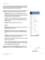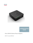
1
ADSL2+ Gateway
with VoIP
Model No.
AG310
User Guide
ADSL2+ Gateway with VoIP
Copyright and Trademarks
Specifications are subject to change without notice. Linksys is a registered trademark or trademark of Cisco
Systems, Inc. and/or its affiliates in the U.S. and certain other countries. Copyright © 2007 Cisco Systems, Inc. All
rights reserved. Other brands and product names are trademarks or registered trademarks of their respective
holders.
How to Use this Guide
Your Guide to the ADSL Gateway has been designed to make understanding networking with the Gateway easier
than ever. Look for the following items when reading this User Guide:
This checkmark means there is a Note of interest and
is something you should pay special attention to while
using the Gateway.
This exclamation point means there is a Caution or
Warning and is something that could damage your
property or the Gateway.
This question mark provides you with a reminder about
something you might need to do while using the Gateway.
In addition to these symbols, there are definitions for technical terms that are presented like this:
word: definition.
Also, each figure (diagram, screenshot, or other image) is provided with a figure number and description, like
this:
Figure 0-1: Sample Figure Description
Figure numbers and descriptions can also be found in the “List of Figures” section in the “Table of Contents”.
AG310-UG-61020NC RR
ADSL2+ Gateway with VoIP
Table of Contents
Chapter 1: Introduction
1
Welcome
What’s in this User Guide?
1
2
Chapter 2: Planning Your Network
3
The Gateway’s Functions
IP Addresses
Chapter 3: Getting to Know the ADSL Gateway
Back Panel
LEDs on the Front and Side Panel
Chapter 4: Connecting the ADSL2+ Gateway with VoIP
Overview
Connecting the Gateway to a Computer
Chapter 5: Using the Interactive Voice Response Menu
Overview
Accessing the Interactive Voice Response Menu
Using the Interactive Voice Response Menu
Entering a Password
Configuring the Settings for Your Internet Phone Service
Chapter 6: Configuring the ADSL2+ Gateway
Overview
How to Access the Web-Based Utility
The Setup - Basic Setup Tab
The Setup - DDNS Tab
The Setup - Advanced Routing Tab
The Setup - Voice Tab
The Security - Firewall Tab
The Security - VPN Tab
The Access Restriction - Internet Access Tab
The Applications & Gaming - Single Port Forwarding Tab
The Applications & Gaming - Port Range Forwarding Tab
The Applications & Gaming - Port Triggering Tab
3
3
5
5
6
7
7
7
8
9
9
9
9
13
13
14
14
16
16
22
23
25
33
34
37
39
40
40
ADSL2+ Gateway with VoIP
The Applications & Gaming - DMZ Tab
The Applications & Gaming - QoS Tab
The Administration - Management Tab
The Administration - Reporting Tab
The Administration - Diagnostics Tab
The Administration - Backup & Restore Tab
The Administration - Factory Defaults Tab
The Administration - Firmware Upgrade Tab
The Administration - Reboot Tab
The Status - Gateway Tab
The Status - Local Network Tab
The Status - DSL Connection Tab
Appendix A: Troubleshooting
Common Problems and Solutions
Frequently Asked Questions
Appendix B: Finding the MAC Address and IP Address
for Your Ethernet Adapter
Windows 98 or Me Instructions
Windows 2000 or XP Instructions
Appendix C: Upgrading Firmware
Appendix D: Glossary
Appendix E: Specifications
Appendix F: Warranty Information
Appendix G: Regulatory Information
Appendix H: Contact Information
41
41
43
46
47
47
48
48
49
49
49
50
51
51
60
64
64
65
66
67
72
74
75
81
ADSL2+ Gateway with VoIP
List of Figures
Figure 2-1: Network
Figure 3-1: Back Panel
Figure 3-2: Front Panel
Figure 4-1: Connect the ADSL Line
Figure 4-2: Connect the Voice Line
Figure 4-3: Connect a Phone
Figure 4-4: Connect a PC
Figure 4-5: Connect the Power
Figure 6-1: Login Screen
Figure 6-2: Basic Setup
Figure 6-3: RFC 1483 Bridged - Dynamic IP
Figure 6-4: RFC 1483 Bridged - Static IP
Figure 6-5: RFC 1483 Routed
Figure 6-6: IPoA
Figure 6-7: RFC 2516 PPPoE
Figure 6-8: RFC 2364 PPPoA
Figure 6-9: Bridged Mode Only
Figure 6-10: Optional Settings
Figure 6-11: Advanced DHCP
Figure 6-12: DynDNS.org
Figure 6-13: TZO.com
Figure 6-14: Advanced Routing
Figure 6-15: Routing Table
Figure 6-16: PVC Routing
Figure 6-17: Setup - Voice - Info
Figure 6-18: Setup - Voice - System
Figure 6-19: Setup - Voice - User 1
Figure 6-20: Setup - Voice - PSTN User
Figure 6-21: Firewall
Figure 6-22: Firewall Log
Figure 6-23: The VPN Panel
Figure 6-24: VPN Settings Summary
3
5
6
7
7
8
8
8
16
16
17
18
18
18
19
19
20
20
21
22
22
23
24
24
25
29
30
32
33
33
34
34
ADSL2+ Gateway with VoIP
Figure 6-25: Advanced VPN Settings
Figure 6-26: VPN Log
Figure 6-27: Internet Access
Figure 6-28: Internet Policy Summary
Figure 6-29: List of PCs
Figure 6-30: Add/Edit Service
Figure 6-31: Single Port Forwarding
Figure 6-32: Port Range Forwarding
Figure 6-33: Port Triggering
Figure 6-34: DMZ
Figure 6-35: QoS
Figure 6-36: Edit List of QoS Settings
Figure 6-37: Management
Figure 6-38: Allowed IP - IP Range
Figure 6-39: Reporting
Figure 6-40: System Log
Figure 6-41: Ping Test
Figure 6-42: Backup&Restore
Figure 6-43: Factory Defaults
Figure 6-44: Firmware Upgrade
Figure 6-45: Reboot
Figure 6-46: Gateway
Figure 6-47: Local Network
Figure 6-48: DHCP Active IP Table
Figure 6-49: ARP/RARP Table
Figure 6-50: Status - DSL Connection
Figure B-1: IP Configuration Screen
Figure B-2: MAC Address/Adapter Address
Figure B-3: MAC Address/Physical Address
Figure C-1: Firmware Upgrade
36
36
37
37
38
38
39
40
40
41
41
42
43
44
46
46
47
47
48
48
49
49
49
50
50
50
64
64
65
66
ADSL2+ Gateway with VoIP
Chapter 1: Introduction
Welcome
Thank you for choosing the AG310 ADSL2+ Gateway with VoIP. This Gateway will provide your computers with a
high-speed Internet connection as well as access to local resources, including files and printers.
How does the Gateway do all of this? By connecting the Internet, as well as your computers and peripherals, to
the Gateway, you create a LAN, or Local Area Network. The Gateway lets devices on the network communicate
with each other, and it can direct and control communications for your network.
lan (local area network): The computers and
networking products that make up the network in
your home or office.
To protect your data and privacy, the Gateway features an advanced firewall to keep out Internet intruders.
Sensitive communications can be protected by powerful data encryption. In addition, you can safeguard your
family with parental control features such as Internet access restrictions and keyword blocking. You can
configure the Gateway’s settings through the easy-to-use, browser-based utility.
But what does all of this mean?
Networks are useful tools for sharing Internet access and computer resources. You can access one printer from
different computers and access data located on another computer’s hard drive. Networks are even used for
playing multiplayer video games. So, networks not only are useful in homes and offices, but also can be fun.
With your PCs and peripherals all connected to each other and to the Internet, you can now share files and
Internet access—and even play games. All the while, the ADSL Gateway protects your network from
unauthorized and unwelcome users.
Linksys recommends using the Setup CD-ROM for first-time installation of the Gateway. If you do not wish to run
the Setup Wizard on the Setup CD-ROM, then use the instructions in this Guide to help you connect the Gateway,
set it up, and configure it to bridge your network and the Internet. These instructions should be all you need to get
the most out of the ADSL Gateway.
Chapter 1: Introduction
Welcome
network: a series of computers or devices
connected for the purpose of data sharing,
storage, and/or transmission between users
1
ADSL2+ Gateway with VoIP
What’s in this User Guide?
This user guide covers the steps for setting up and using the ADSL Gateway.
• Chapter 1: Introduction
This chapter describes applications of the ADSL Gateway and this User Guide.
• Chapter 2: Planning Your Network
This chapter describes the basics of networking.
• Chapter 3: Getting to Know the ADSL Gateway
This chapter describes the physical features of the Gateway.
• Chapter 4: Connecting the ADSL Gateway
This chapter instructs you on how to connect the Gateway to your network.
• Chapter 5: Using the Interactive Voice Response Menu
This chapter explains how to use the Interactive Voice Response Menu.
• Chapter 6: Configuring the ADSL2+ Gateway
This chapter explains how to use the Web-based Utility to configure the settings on the Gateway.
• Appendix A: Troubleshooting
This appendix describes some problems and solutions, as well as frequently asked questions, regarding
installation and use of the ADSL Gateway.
• Appendix B: Finding the MAC Address and IP Address for your Ethernet Adapter.
This appendix describes how to find the MAC address for your computer’s Ethernet adapter so you can use
the MAC filtering and/or MAC address cloning feature of the Gateway.
• Appendix C: Upgrading Firmware
This appendix instructs you on how to upgrade the firmware on the Gateway if you should need to do so.
• Appendix D: Glossary
This appendix gives a brief glossary of terms frequently used in networking.
• Appendix E: Specifications
This appendix provides the technical specifications for the Gateway.
• Appendix F: Warranty Information
This appendix supplies the warranty information for the Gateway.
• Appendix G: Regulatory Information
This appendix supplies the regulatory information regarding the Gateway.
• Appendix H: Contact Information
This appendix provides contact information for a variety of Linksys resources, including Technical Support.
Chapter 1: Introduction
What’s in this User Guide?
2
ADSL2+ Gateway with VoIP
Chapter 2: Planning Your Network
The Gateway’s Functions
A Gateway is a network device that connects two networks together.
In this instance, the Gateway connects your Local Area Network (LAN), or the group of computers in your home or
office, to the Internet. The Gateway processes and regulates the data that travels between these two networks.
The Gateway’s NAT feature protects your network of computers so users on the public, Internet side cannot “see”
your computers. This is how your network remains private. The Gateway protects your network by inspecting
every packet coming in through the Internet port before delivery to the appropriate computer on your network.
The Gateway inspects Internet port services like the web server, ftp server, or other Internet applications, and, if
allowed, it will forward the packet to the appropriate computer on the LAN side.
Remember that the Gateway’s ports connect to two sides. The LAN ports connect to the LAN, and the ADSL port
connects to the Internet. The LAN ports transmit data at 10/100Mbps.
IP Addresses
What’s an IP Address?
IP stands for Internet Protocol. Every device on an IP-based network, including computers, print servers, and
Gateways, requires an IP address to identify its “location,” or address, on the network. This applies to both the
Internet and LAN connections. There are two ways of assigning an IP address to your network devices. You can
assign static IP addresses or use the Gateway to assign IP addresses dynamically.
Static IP Addresses
A static IP address is a fixed IP address that you assign manually to a computer or other device on the network.
Since a static IP address remains valid until you disable it, static IP addressing ensures that the device assigned
it will always have that same IP address until you change it. Static IP addresses must be unique and are
commonly used with network devices such as server computers or print servers.
Chapter 2: Planning Your Network
The Gateway’s Functions
Figure 2-1: Network
ip (internet protocol): a protocol used to send data
over a network
NOTE: Since the Gateway is a device that connects
two networks, it needs two IP addresses—one for
the LAN, and one for the Internet. In this User Guide,
you’ll see references to the “Internet IP address”
and the “LAN IP address.”
Since the Gateway uses NAT technology, the only IP
address that can be seen from the Internet for your
network is the Gateway’s Internet IP address.
However, even this Internet IP address can be
blocked, so that the Gateway and network seem
invisible to the Internet—see the Block WAN
Requests description under Security in “Chapter 6:
Configuring the ADSL2+ Gateway.”
3
ADSL2+ Gateway with VoIP
Since you use the Gateway to share your DSL Internet connection, contact your ISP to find out if they have
assigned a static IP address to your account. If so, you will need that static IP address when configuring the
Gateway. You can get that information from your ISP.
Dynamic IP Addresses
A dynamic IP address is automatically assigned to a device on the network, such as computers and print servers.
These IP addresses are called “dynamic” because they are only temporarily assigned to the computer or device.
After a certain time period, they expire and may change. If a computer logs onto the network (or the Internet) and
its dynamic IP address has expired, the DHCP server will automatically assign it a new dynamic IP address.
DHCP (Dynamic Host Configuration Protocol) Servers
Computers and other network devices using dynamic IP addressing are assigned a new IP address by a DHCP
server. The computer or network device obtaining an IP address is called the DHCP client. DHCP frees you from
having to assign IP addresses manually every time a new user is added to your network.
A DHCP server can either be a designated computer on the network or another network device, such as the
Gateway. By default, the Gateway’s DHCP Server function is enabled.
If you already have a DHCP server running on your network, you must disable one of the two DHCP servers. If you
run more than one DHCP server on your network, you will experience network errors, such as conflicting IP
addresses. To disable DHCP on the Gateway, see the DHCP section in “Chapter 6: Configuring the ADSL2+
Gateway.”
Chapter 2: Planning Your Network
IP Addresses
4
ADSL2+ Gateway with VoIP
Chapter 3: Getting to Know the ADSL Gateway
Back Panel
The Gateway’s ports and Reset button are located on the back panel.
Figure 3-1: Back Panel
DSL
The DSL port connects to the ADSL line from your telephone wall jack.
Line
The Line port connects your standard telephone and converts the signal to VoIP technology.
Phone
The Phone port connects to an analog phone (or fax machine) with an RJ-11 telephone cable. The
primary purpose of this port is to allow a phone to be connected that will function during power outages,
in case of an emergency.
Ethernet (1-4)
The Ethernet ports connect to your computers and other network devices.
Reset Button
There are two ways to reset the Gateway's factory defaults. Either press the Reset Button, for
approximately ten seconds, or restore the defaults from the Factory Defaults screen of the
Administration tab in the Gateway’s web-based utility.
Power
The Power port is where you will connect the power adapter.
Chapter 3: Getting to Know the ADSL Gateway
Back Panel
IMPORTANT: Resetting the Gateway to factory
defaults will erase all of your settings
(including Internet connection and other
settings) and replace them with the factory
defaults. Do not reset the Gateway if you want
to retain these settings.
5
ADSL2+ Gateway with VoIP
LEDs on the Front and Side Panel
The Gateway's LEDs, which indicate network activity, are located on the front and side panel.
Figure 3-2: Front Panel
POWER
Green. The POWER LED lights up when the Gateway is powered on.
ETHERNET (1-4) Green. The ETHERNET LED serves two purposes. If the LED is continuously lit, the Gateway is
successfully connected to a device through the LAN port. If the LED is flashing, it is an
indication of any network activity.
PHONE
Green. The PHONE LED is lit solid when a telephone or fax machine has an active or registered
connection to your Internet Telephony Service Provider (ITSP) through the PHONE port. It
flashes when the phone is being used or is off the hook.
LINE
Green. The LINE LED lights up when the a telephone or fax machine has an active connection
to traditional phone service through the LINE port.
DSL
Green. The DSL LED lights up whenever there is a successful DSL connection. The LED blinks
while the Gateway is establishing the ADSL connection.
INTERNET
Green. The INTERNET LED lights up green when an Internet connection to the Internet Service
Provider (ISP) is established. The INTERNET LED lights up red when the connection to the ISP
fails.
Chapter 3: Getting to Know the ADSL Gateway
LEDs on the Front and Side Panel
6
ADSL2+ Gateway with VoIP
Chapter 4: Connecting the ADSL2+ Gateway with VoIP
Overview
The installation technician from your ISP should have left the setup information for the modem with you after
installing your broadband connection. If not, you can call your ISP to request that data.
After you have the setup information you need for your specific type of Internet connection, you can begin
installation and setup of the Gateway. Continue to “Connecting the Gateway to a Computer.”
Connecting the Gateway to a Computer
1. Make sure that all of your network’s hardware is powered off, including the Gateway and all computers.
2. Connect a phone cable from the DSL port on the Gateway’s back panel to the wall jack of the ADSL line. A
small device called a microfilter (not included) may be necessary between each phone and wall jack to
prevent interference. Contact your ISP if you have any questions.
3. Connect another phone cable from the Line port on the Gateway’s back panel to the Voice connection on the
DSL microfilter or wall jack.
Figure 4-1: Connect the ADSL Line
NOTE: A small device called a microfilter (not included) may be necessary between each phone
and wall jack to prevent interference. Contact your ISP if you have any questions.
IMPORTANT: For countries that have phone jacks with RJ-11 connectors, make sure to only place
the microfilters between the phone and the wall jack and not between the Gateway and the wall
jack or your ADSL will not connect.
For countries that do not have phone jacks with RJ-11 connectors (e.g. France, Sweden,
Switzerland, United Kingdom, etc.), except for ISDN users, the microfilter has to be used between
the Gateway and the wall jack, because the microfilter will have the RJ-11 connector.
Annex B users (E1 and DE versions of the Gateway) must use the included special cable to connect
the Gateway to the wall jack (RJ-45 to RJ-12). If you require splitters or special jacks, please
contact your service provider.
Chapter 4: Connecting the ADSL2+ Gateway with VoIP
Overview
Figure 4-2: Connect the Voice Line
7
ADSL2+ Gateway with VoIP
4. Connect an analog telephone to the Phone port on the Gateway’s back panel.
5. Connect one end of an Ethernet network cable to one of the Ethernet ports (labeled 1-4) on the back of the
Gateway, and the other end to an Ethernet port on a computer.
Repeat this step to connect more computers, a switch, or other network devices to the Gateway.
6. Connect the power adapter to the Gateway’s Power port, and then plug the power adapter into a power outlet.
NOTE: You should always plug the Gateway’s power adapter into a power strip with
surge protection.
The Power LED will immediately light up green. The Power LED will flash for a few seconds, and then it will be
solidly lit when the self-test is complete. If the LED flashes for one minute or longer, see “Appendix A:
Troubleshooting.”
Figure 4-3: Connect a Phone
7. Power on one of your computers that is connected to the Gateway.
Figure 4-4: Connect a PC
Figure 4-5: Connect the Power
Chapter 4: Connecting the ADSL2+ Gateway with VoIP
8
ADSL2+ Gateway with VoIP
Chapter 5: Using the Interactive Voice Response Menu
Overview
NOTE: If your ITSP sent you the Voice Gateway, then it may be pre-configured for you, and you do
not need to change any settings. Refer to the instructions supplied by your service provider for
more information.
You may need to manually configure the Voice Gateway by entering the settings provided by your Internet
Telephony Service Provider (ITSP). This chapter explains how to use the Interactive Voice Response Menu to
configure the Voice Gateway’s network settings. You will use the telephone’s keypad to enter your commands and
select choices, and the Voice Gateway will use voice responses.
For more advanced configuration, refer to “Chapter 6: Configuring the ADSL2+ Gateway”
Accessing the Interactive Voice Response Menu
1. Use a telephone connected to the PHONE port of the Voice Gateway. (You can only access the Interactive
Voice Response Menu through an analog telephone, not any of the Internet phones.)
2. Press **** (in other words, press the star key four times).
3. Wait until you hear “Linksys configuration menu. Please enter the option followed by the # (pound) key or
hang up to exit.”
4. Refer to the following table that lists actions, commands, menu choices, and descriptions. After you select an
option, press the # (pound) key. To exit the menu, hang up the telephone.
Using the Interactive Voice Response Menu
While entering a value, such as an IP address, you may exit without entering any changes. Press the * (star) key
twice within half a second. Otherwise, the * will be treated as a decimal point or dot.
After entering a value, such as an IP address, press the # (pound) key to indicate you have finished your selection.
To save the new setting, press 1. To review the new setting, press 2. To re-enter the new setting, press 3. To
cancel your entry and return to the main menu, press * (star).
Chapter 5: Using the Interactive Voice Response Menu
Overview
9
ADSL2+ Gateway with VoIP
For example, to enter the IP address 191.168.1.105 by keypad, press these keys: 191*168*1*105. Press the #
(pound) key to indicate that you have finished entering the IP address. Then press 1 to save the IP address or
press the * (star) key to cancel your entry and return to the main menu.
If the menu is inactive for more than one minute, the Voice Gateway will time out. You will need to re-enter the
menu by pressing ****.
The settings you have saved will take effect after you have hung up the telephone. The Voice Gateway may reboot
at this time.
Table 1: Interactive Voice Response Menu
Action
Command (press these
keys on the telephone)
Enter Interactive Voice
Response Menu
****
Use this command to enter the
Interactive Voice Response
Menu. Do not press any other
keys until you hear, “Linksys
configuration menu. Please
enter the option followed by
the # (pound) key or hang up to
exit.”
Check Internet Connection
Type
100
Hear the Internet connection
type of the Voice Gateway.
Check Internet IP Address
110
Hear the IP address assigned
to the Voice Gateway’s Internet
(external) interface.
Check Network Mask (or
Subnet Mask)
120
Hear the network or subnet
mask assigned to the Voice
Gateway.
Check Gateway IP Address
130
Hear the IP address of the
Voice Gateway (usually the
network router).
Check MAC Address
140
Hear the MAC address of the
Voice Gateway in hexadecimal
string format.
Check Firmware Version
150
Hear the version number of the
firmware currently running on
the Voice Gateway.
Chapter 5: Using the Interactive Voice Response Menu
Using the Interactive Voice Response Menu
Choices
Description
10
ADSL2+ Gateway with VoIP
Table 1: Interactive Voice Response Menu
Action
Command (press these
keys on the telephone)
Check Primary DNS Server IP
Address
160
Hear the IP address of the
primary DNS (Domain Name
Service) server.
Check Internet Web Server Port
170
Hear the port number of the
Internet Web server used for
the web-based utility.
Check Local IP Address
210
Hear the local IP address of the
Voice Gateway.
Set Internet Connection Type
101
Press 0 to use DHCP.
Press 1 to use a static IP
address.
Press 2 to use PPPoE.
Select the type of Internet
connection you are using.
Refer to the documentation
supplied by your Internet
Service Provider (ISP).
Set Static IP Address
111
Enter the IP address using
numbers on the telephone
keypad. Use the * (star) key
when entering a decimal point.
First, set the Internet
Connection Type to static IP
address; otherwise, you will
hear, “Invalid Option,” if you try
to set the static IP address.
Set Network (or Subnet) Mask
121
Enter the network or subnet
mask using numbers on the
telephone keypad. Use the *
(star) key when entering a
decimal point.
First, set the Internet
Connection Type to static IP
address; otherwise, you will
hear, “Invalid Option,” if you try
to set the network or subnet
mask.
Set Gateway IP Address
131
Enter the IP address using
numbers on the telephone
keypad. Use the * (star) key
when entering a decimal point.
First, set the Internet
Connection Type to static IP
address; otherwise, you will
hear, “Invalid Option,” if you try
to set the gateway IP address.
Set Primary DNS Server IP
Address
161
Enter the IP address using
numbers on the telephone
keypad. Use the * (star) key
when entering a decimal point.
First, set the Internet
Connection Type to static IP
address; otherwise, you will
hear, “Invalid Option,” if you try
to set the IP address of the
primary DNS server.
Chapter 5: Using the Interactive Voice Response Menu
Using the Interactive Voice Response Menu
Choices
Description
11
ADSL2+ Gateway with VoIP
Table 1: Interactive Voice Response Menu
Action
Command (press these
keys on the telephone)
Choices
Description
Set the Mode
201
Press 0 to select the router/
NAT mode.
Press 1 to select the bridge/
switch mode.
If the Voice Gateway acts as
the router for your network,
use the router/NAT mode.
If your network already has a
router, use the bridge/switch
mode.
Enable/Disable WAN Access to
the Web-based Utility
7932
Manual Reboot
732668
Factory Reset
73738
User Factory Reset
877778
Chapter 5: Using the Interactive Voice Response Menu
Using the Interactive Voice Response Menu
Press 1 to enable.
Press 0 to disable.
Use this setting to enable or
disable WAN access to the
web-based utility. (This Utility
lets you configure the Voice
Gateway.)
After you hear, “Option
successful,” hang up the
phone. The Voice Gateway will
automatically reboot.
Press 1 to confirm.
Press * (star) to cancel.
Press 1 to confirm.
Press * (star) to cancel.
If necessary, enter the
password. The Voice Gateway
will request confirmation; enter
1 to confirm. You will hear,
“Option successful.” Hang up
the phone. The Voice Gateway
will reboot, and all settings will
be reset to their factory default
settings.
NOTE: This feature may be protected by a
password available only from your ITSP.
If you need to enter a password, refer to the
following section, “Entering a Password.”
The Voice Gateway will request
confirmation; enter 1 to
confirm. You will hear, “Option
successful.” Hang up the
phone. The Voice Gateway will
reboot and all userconfigurable settings will be
reset to their factory default
settings.
12
ADSL2+ Gateway with VoIP
Entering a Password
NOTE: These bulleted instructions only apply when you are entering a password. At all other
times, pressing a number only selects a number, not a letter or punctuation mark.
You may be prompted to enter a password when you want to reset the Voice Gateway to its factory default
settings. To enter the password, use the phone’s keypad, and follow the appropriate instructions.
• To enter A, B, C, a, b, or c — press 2.
• To enter D, E, F, d, e, or f — press 3.
• To enter G, H, I, g, h, or i — press 4.
• To enter J, K, L, j, k, or l — press 5.
• To enter M, N, O, m, n, or o — press 6.
• To enter P, Q, R, S, o, q, r, or s — press 7.
• To enter T, U, V, t, u, or v — press 8.
• To enter W, X, Y, Z, w, x, y, or z — press 9.
• To enter all other characters, press 0.
For example, to enter the password phone@321 by keypad, press these keys: 746630321. Then press the #
(pound) key to indicate that you have finished entering the password. To cancel your entry and return to the main
menu, press * (star).
Configuring the Settings for Your Internet Phone Service
If you want to change the settings for your Internet phone service, refer to the instructions provided by your ITSP
and “Chapter 6: Configuring the ADSL2+ Gateway”
Chapter 5: Using the Interactive Voice Response Menu
Entering a Password
13
ADSL2+ Gateway with VoIP
Chapter 6: Configuring the ADSL2+ Gateway
Overview
Follow the steps in this chapter and use the Gateway’s web-based utility to configure the ADSL2+ Gateway with
VoIP. This chapter will describe each web page in the Utility and each page’s key functions. The utility can be
accessed via your web browser through use of a computer connected to the Gateway. For a basic network setup,
most users only have to use the following screens of the Utility:
HAVE YOU: Enabled TCP/IP on your
computers? Computers communicate over the
network with this protocol. Refer to Windows
Help for more information on TCP/IP.
• Basic Setup. On the Basic Setup screen, enter the settings provided by your ISP.
• Management. Click the Administration tab and then the Management tab. The Gateway’s default username
and password is admin. To secure the Gateway, change the Password from its default.
NOTE: For added security, you should change
the password through the Administration tab.
There are six main tabs: Setup, Security, Access Restrictions, Applications & Gaming, Administration, and Status.
Additional tabs will be available after you click one of the main tabs.
Setup
• Basic Setup. Enter the Internet connection and network settings on this screen.
• DDNS. To enable the Gateway’s Dynamic Domain Name System (DDNS) feature, complete the fields on this
screen.
• Advanced Routing. On this screen, you can alter NAT and routing configurations.
• Voice. This option has four different screens, the default is Info.
• Info. This screen displays voice-related status information about the Gateway.
• System. Use this screen to configure the user password.
• User 1. Use this screen to configure call forward, speed dial, supplementary service, and ring settings for
the Internet phone line.
• PSTN User. PSTN stands for Public Switched Telephone Network, which is the network that traditional
phone service uses. Use this screen to configure call forward, speed dial, and ring settings for the PSTN
line.
Chapter 6: Configuring the ADSL2+ Gateway
Overview
14
ADSL2+ Gateway with VoIP
Security
• Firewall. To disable or enable the firewall, set up filters, and block WAN requests, click this tab.
• VPN. To enable or disable Virtual Private Network (VPN) passthrough, or to set up an IPSec VPN tunnel, use
this screen.
vpn (virtual private network): a security
measure to protect data as it leaves one
network and goes to another over the Internet.
Access Restrictions
• Internet Access. This screen allows you to control the Internet usage and traffic on your local network.
Applications & Gaming
• Single Port Forwarding. Use this screen to set up common services or applications that require forwarding on
a single port.
• Port Range Forwarding. To set up public services or other specialized Internet applications that require
forwarding on a range of ports, use this screen.
• Port Triggering. To set up triggered ranges and forwarded ranges for Internet applications, click this tab.
• DMZ. To allow one local computer to be exposed to the Internet for use of special-purpose services, use this
screen.
• QoS. Use Quality of Service (QoS) to assign different priority levels to different types of data transmissions.
Administration
• Management. On this screen, alter Gateway access, Simple Network Management Protocol (SNMP), Universal
Plug and Play (UPnP), IGMP-Proxy (IGMP stands for Internet Group Multicast Protocol), and IGMP-Snooping
settings.
• Reporting. If you want to view or save activity logs, click this tab.
• Diagnostics. Use this screen to run a Ping test.
• Backup&Restore. On this screen, you can back up or restore the Gateway’s configuration.
• Factory Defaults. If you want to restore the Gateway’s factory default settings, use this screen.
• Firmware Upgrade. Click this tab if you want to upgrade the Gateway’s firmware.
Chapter 6: Configuring the ADSL2+ Gateway
Overview
15
ADSL2+ Gateway with VoIP
• Reboot. If you need to do a hard or soft reboot of the Gateway, use this screen.
Status
• Gateway. This screen provides status information about the Gateway.
• Local Network. This provides status information about the local network.
• DSL Connection. This screen provides status information about the DSL connection.
Figure 6-1: Login Screen
How to Access the Web-Based Utility
To access the web-based utility, launch Internet Explorer or Netscape Navigator, and enter the Gateway’s default
IP address, 192.168.1.1, in the Address field. Then press Enter.
A login screen will appear (Windows XP users will see a similar screen). Enter admin (the default user name) in
the User Name field, and enter admin (the default password) in the Password field. Then click the OK button.
The Setup - Basic Setup Tab
The first screen that appears is the Basic Setup tab. This tab allows you to change the Gateway's general
settings. Change these settings as described here and click the Save Settings button to save your changes, or
click the Cancel Changes button to cancel your changes.
Internet Setup
PVC Connection. If your ADSL account provides multiple permanent virtual circuits (PVCs), use this control to
specify the one you will configure. The Gateway can handle up to eight PVCs. They may be used to carry different
services or connect to different networks. Each PVC is identified by a unique combination of VCI and VPI numbers
(see “Virtual Circuit,” below).
Internet Connection Type. The Gateway supports six Encapsulation methods: RFC 1483 Bridged, RFC 1483
Routed, IPoA, RFC 2516 PPPoE, RFC 2364 PPPoA, and Bridge Mode Only. Select the appropriate type of
encapsulation from the drop-down menu. Each Basic Setup screen and available features will differ depending
on what type of encapsulation you select.
Figure 6-2: Basic Setup
Chapter 6: Configuring the ADSL2+ Gateway
How to Access the Web-Based Utility
16
ADSL2+ Gateway with VoIP
VC Settings
You will configure your Virtual Circuit (VC) settings in this section.
Multiplexing. Select LLC or VC, depending on your ISP.
QoS Type. Select from the drop-down menu:
• UBR (Unspecific Bit Rate) for applications that are none-time sensitive, such as e-mail.
• CBR (Continuous Bit Rate) to specify fixed bandwidth for voice or data traffic.
• VBR (Variable Bite Rate) for bursty traffic and bandwidth-sharing with other applications.
Pcr Rate. For the Peak Cell Rate, divide the DSL line rate by 424 to get the maximum rate the sender can send
cells. Enter the rate in the field (if required by your service provider).
Scr Rate. The Sustain Cell Rate sets the average cell rate that can be transmitted. The SCR value is normally less
than the PCR value. Enter the rate in the field (if required by your service provider).
Autodetect. Select Enable to have the settings automatically entered, or select Disable to enter the values
manually.
Virtual Circuit. These fields consist of two items: VPI (Virtual Path Identifier) and VCI (Virtual Channel Identifier).
Your ISP will provide the correct settings for these fields.
DSL Modulation. Select the appropriate DSL Modulation as provided by your ISP. The default is Multimode, other
available options are T1.413, G.dmt, G.lite, ADSL2, and ADSL2+.
IP Settings
Follow the instructions in the section for your type of encapsulation.
RFC 1483 Bridged
Dynamic IP
IP Settings. Select Obtain an IP Address Automatically if your ISP says you are connecting through a
dynamic IP address.
Figure 6-3: RFC 1483 Bridged - Dynamic IP
Chapter 6: Configuring the ADSL2+ Gateway
The Setup - Basic Setup Tab
17
ADSL2+ Gateway with VoIP
Static IP
If you are required to use a permanent (static) IP address to connect to the Internet, then select Use the
following IP Address.
• Internet IP Address. This is the Gateway’s IP address, when seen from the WAN, or the Internet. Your ISP
will provide you with the IP Address you need to specify here.
• Subnet Mask. This is the Gateway’s Subnet Mask. Your ISP will provide you with the Subnet Mask.
• Gateway. Your ISP will provide you with the default Gateway Address, which is the ISP server’s IP
address.
• Primary DNS (Required) and Secondary DNS (Optional). Your ISP will provide you with at least one DNS
(Domain Name System) Server IP Address.
Figure 6-4: RFC 1483 Bridged - Static IP
RFC 1483 Routed
If you are required to use RFC 1483 Routed, then select RFC 1483 Routed.
• Internet IP Address. This is the Gateway’s IP address, when seen from the WAN, or the Internet. Your ISP
will provide you with the IP Address you need to specify here.
• Subnet Mask. This is the Gateway’s Subnet Mask. Your ISP will provide you with the Subnet Mask.
• Gateway. Your ISP will provide you with the default Gateway Address, which is the ISP server’s IP
address.
• Primary DNS (Required) and Secondary DNS (Optional). Your ISP will provide you with at least one DNS
(Domain Name System) Server IP Address.
Figure 6-5: RFC 1483 Routed
IPoA
If you are required to use Internet Protocol over ATM (Asynchronous Transfer Mode), then select IPoA.
• Internet IP Address. This is the Gateway’s IP address, when seen from the WAN, or the Internet. Your ISP
will provide you with the IP Address you need to specify here.
• Subnet Mask. This is the Gateway’s Subnet Mask. Your ISP will provide you with the Subnet Mask.
• Gateway. Your ISP will provide you with the default Gateway Address, which is the ISP server’s IP
address.
Chapter 6: Configuring the ADSL2+ Gateway
The Setup - Basic Setup Tab
Figure 6-6: IPoA
18
ADSL2+ Gateway with VoIP
• Primary DNS (Required) and Secondary DNS (Optional). Your ISP will provide you with at least one DNS
(Domain Name System) Server IP Address.
RFC 2516 PPPoE
Some DSL-based ISPs use PPPoE (Point-to-Point Protocol over Ethernet) to establish Internet connections. If
you are connected to the Internet through a DSL line, check with your ISP to see if they use PPPoE. If they do,
you will have to enable PPPoE.
• Service Name. Enter the name of your PPPoE service in this field.
• User Name and Password. Enter the User Name and Password provided by your ISP.
• Connect on Demand: Max Idle Time. You can configure the Gateway to disconnect the Internet
connection after it has been inactive for a specified period of time (Max Idle Time). If your Internet
connection has been terminated due to inactivity, Connect on Demand enables the Gateway to
automatically re-establish your connection as soon as you attempt to access the Internet again. To use
this option, click the Connect on Demand radio button. In the Max Idle Time field, enter the number of
minutes you want to have elapsed before your Internet connection terminates.
Figure 6-7: RFC 2516 PPPoE
• Keep Alive: Redial Period. If you select this option, the Gateway will periodically check your Internet
connection. If you are disconnected, then the Gateway will automatically re-establish your connection. To
use this option, click the Keep Alive radio button. In the Redial Period field, specify how often you want
the Gateway to check the Internet connection. The default Redial Period is 20 seconds.
• Second PPPoE. This option can be enabled if you have a second PPPoE login provided by your ISP. The
options for the Second PPPoE login include the options listed above and the Match Domain Name option
described below.
• Match Domain Name. This option appears when Second PPPoE is enabled. Enter the domain name
provided by your ISP.
RFC 2364 PPPoA
Some DSL-based ISPs use PPPoA (Point-to-Point Protocol over ATM) to establish Internet connections. If you
are connected to the Internet through a DSL line, check with your ISP to see if they use PPPoA. If they do, you
will have to enable PPPoA.
• User Name and Password. Enter the User Name and Password provided by your ISP.
Figure 6-8: RFC 2364 PPPoA
Chapter 6: Configuring the ADSL2+ Gateway
The Setup - Basic Setup Tab
19
ADSL2+ Gateway with VoIP
• Connect on Demand: Max Idle Time. You can configure the Gateway to disconnect the Internet
connection after it has been inactive for a specified period of time (Max Idle Time). If your Internet
connection has been terminated due to inactivity, Connect on Demand enables the Gateway to
automatically re-establish your connection as soon as you attempt to access the Internet again. To use
this option, click the Connect on Demand radio button. In the Max Idle Time field, enter the number of
minutes you want to have elapsed before your Internet connection terminates.
• Keep Alive: Redial Period. If you select this option, the Gateway will periodically check your Internet
connection. If you are disconnected, then the Gateway will automatically re-establish your connection. To
use this option, click the Keep Alive radio button. In the Redial Period field, specify how often you want
the Gateway to check the Internet connection. The default Redial Period is 20 seconds.
Bridged Mode Only
If you are using your Gateway as a bridge, which makes the Gateway act like a stand-alone modem, select
Bridged Mode Only. All NAT and routing settings are disabled in this mode.
Optional Settings (required by some ISPs)
• Host Name and Domain Name. These fields allow you to supply a host and domain name for the Gateway.
Some ISPs require these names as identification. You may have to check with your ISP to see if your
broadband Internet service has been configured with a host and domain name. In most cases, you can leave
these fields blank.
Figure 6-9: Bridged Mode Only
• MTU and Size. The MTU (Maximum Transmission Unit) setting specifies the largest packet size permitted for
network transmission. Select Manual and enter the value desired in the Size field. It is recommended that
you leave this value in the 1200 to 1500 range. By default, MTU is configured automatically.
Network Setup
• Router IP. The values for the Gateway’s Local IP Address and Subnet Mask are shown here. In most cases,
keep the default values.
• Local IP Address. The default value is 192.168.1.1.
• Subnet Mask. The default value is 255.255.255.0.
• Network Address Server Settings (DHCP). Configure the Gateway’s Dynamic Host Configuration Protocol
(DHCP) settings in this section.
Chapter 6: Configuring the ADSL2+ Gateway
The Setup - Basic Setup Tab
Figure 6-10: Optional Settings
20
ADSL2+ Gateway with VoIP
• Local DHCP Server. A Dynamic Host Configuration Protocol (DHCP) server automatically assigns an IP
address to each computer on your network for you. Unless you already have one, it is highly
recommended that you leave the Gateway enabled as a DHCP server. You can also use the Gateway in
DHCP Relay mode.
• DHCP Relay Server. If you enable the DHCP Relay mode for the Local DHCP Server setting, enter the IP
address for the DHCP server in the fields provided.
• Advanced. This button displays a window that lets you reserve addresses in the DHCP range for
particular machines.
• Autodetect LAN DHCP Server. Enable this function if you already have a DHCP server on your LAN and
you wish to continue using it.
• Starting IP Address. Enter a value for the DHCP server to start with when issuing IP addresses. This
value must be 192.168.1. 2 or greater, because the default IP address for the Gateway is 192.168.1.1.
• Maximum Number of DHCP Users. Enter the maximum number of users/clients that can obtain an IP
address. The number will vary depending on the starting IP address entered.
Figure 6-11: Advanced DHCP
• Client Lease Time. The Client Lease Time is the amount of time a computer will be allowed connection to
the Gateway with its current dynamic IP address. Enter the amount of time, in minutes, that the computer
will be “leased” this dynamic IP address.
• Static DNS 1-3. The Domain Name System (DNS) is how the Internet translates domain or website names
into Internet addresses or URLs. Your ISP will provide you with at least one DNS Server IP Address. You
can enter up to three DNS Server IP Addresses here. The Gateway will use these for quicker access to
functioning DNS servers.
• WINS. The Windows Internet Naming Service (WINS) converts NetBIOS names to IP addresses. If you use
a WINS server, enter that server’s IP address here. Otherwise, leave this field blank.
• Time Setting.
• Time Zone. Select the appropriate time zone for the Gateway’s location.
• Time Interval. Select the time interval for clock synchronization. The default value is 3600 seconds (1
hour).
• Automatically adjust clock for daylight saving changes checkbox. Select this if your location
observes daylight saving time.
Chapter 6: Configuring the ADSL2+ Gateway
The Setup - Basic Setup Tab
21
ADSL2+ Gateway with VoIP
• Time Server Address. The default value is Auto. To designate a specific NTP time server, select Manual
and enter the NTP server address in the appropriate field.
When finished making your changes on this tab, click the Save Settings button to save these changes, or click
the Cancel Changes button to undo your changes.
The Setup - DDNS Tab
The Gateway offers a Dynamic Domain Name System (DDNS) feature. DDNS lets you assign a fixed host and
domain name to a dynamic Internet IP address. It is useful when you are hosting your own website, FTP server, or
other server behind the Gateway.
Before you can use this feature, you need to sign up for DDNS service at DynDNS.org or TZO.com.
DDNS
DDNS Service. If your DDNS service is provided by DynDNS.org, then select DynDNS.org from the drop-down
menu. If your DDNS service is provided by TZO.com, then select TZO.com from the drop-down menu.To disable
DDNS Service, select Disabled.
DynDNS.org
• User Name, Password, and Host Name. Enter the User Name, Password, and Host Name of the account you
set up with DynDNS.org.
• Internet IP Address. The Gateway’s current Internet IP Address is displayed here. Because it is dynamic, it
will change.
Figure 6-12: DynDNS.org
• Status. The status of the DDNS service connection is displayed here.
TZO.com
• E-mail Address, Password, and Domain Name. Enter the E-mail Address, Password, and Domain Name of
the account you set up with TZO.
• Internet IP Address. The Gateway’s current Internet IP Address is displayed here. Because it is dynamic, this
will change.
• Status. The status of the DDNS service connection is displayed here.
When finished making your changes on this tab, click the Save Settings button to save these changes, or click
the Cancel Changes button to undo your changes.
Chapter 6: Configuring the ADSL2+ Gateway
The Setup - DDNS Tab
Figure 6-13: TZO.com
22
ADSL2+ Gateway with VoIP
The Setup - Advanced Routing Tab
The Advanced Routing screen allows you to configure the NAT, dynamic routing, and static routing settings.
Advanced Routing
Operating Mode.
In this section, you will configure the Gateway’s general routing settings.
NAT. NAT is a security feature that is enabled by default. It enables the Gateway to translate IP addresses of your
local area network to a different IP address for the Internet. To disable NAT, click the Disabled option.
Dynamic Routing
With Dynamic Routing you can enable the Gateway to automatically adjust to physical changes in the network’s
layout. Using RIP, the Gateway determines the network packets’ route based on the fewest number of hops
between the source and the destination. The RIP protocol regularly broadcasts routing information to other
Gateways on the network.
Figure 6-14: Advanced Routing
RIP. If you have multiple routers, you may want to use the Routing Information Protocol (RIP) so the routers can
exchange routing information with each other. To use RIP, select the Enabled option. Otherwise, keep the default,
Disabled.
Transmit RIP Version. To transmit RIP messages, select the protocol you want: RIP1, RIP1-Compatible (RIP1
broadcasts and RIP2 multicasts), or RIP2. If you don’t want to transmit RIP messages, select None.
Receive RIP Version. To receive RIP messages, select the protocol you want: RIP1 or RIP2. If you don’t want to
receive RIP messages, select None.
Static Routing
If the Gateway is connected to more than one network, it may be necessary to set up a static route between
them. A static route is a pre-determined pathway that network information must travel to reach a specific host or
network. To create a static route, change the following settings:
Select set number. Select the number of the static route from the drop-down menu. The Gateway supports up to
20 static route entries. If you need to delete a route, then select the entry and click the Delete This Entry button.
Chapter 6: Configuring the ADSL2+ Gateway
The Setup - Advanced Routing Tab
23
ADSL2+ Gateway with VoIP
Destination IP Address. The Destination IP Address is the address of the remote network or host to which you
want to assign a static route. Enter the IP address of the host for which you wish to create a static route. If you are
building a route to an entire network, be sure that the network portion of the IP address is set to 0.
Subnet Mask. Enter the Subnet Mask (also known as the Network Mask), which determines which portion of an
IP address is the network portion, and which portion is the host portion.
Figure 6-15: Routing Table
Gateway. Enter the IP address of the gateway device that allows for contact between the Gateway and the
remote network or host.
Hop Count. Hop Count is the number of hops to each node until the destination is reached (16 hops maximum).
Enter the Hop Count in the field provided.
Click the Show Routing Table button to open a screen displaying how data is routed through your local network.
For each route, the Destination LAN IP address, Subnet Mask, Gateway, and Interface are displayed. Click the
Refresh button to update the information. Click the Close button to return to the previous screen.
PVC Routing Policy
If you have multiple PVCs, click the PVC Routing Setting button to configure which outgoing traffic will be routed
over which PVC. A window titled PVC Selection Table will appear.
Please select Active Connection. Open this drop-down list and specify the PVC for which you will select traffic.
Traffic can be selected on the basis of any of the following criteria, alone or in combination:
• Destination (IP address, netmask, and FQDN)
• Source (IP address and netmask)
Figure 6-16: PVC Routing
• Source MAC (MAC address)
• Destination MAC (MAC address)
• Transport protocol (TCP, UDP, or All)
• Dst Port/Scr Port (Destination port and/or source port). If protocol is set to TCP or UDP.
• ALG. Triggering of a particular Application Layer Gateway (FTP, TFTP, H.323, IRC, MMS, GRE, PPTP, SIP, or
RTSP)
• Presence of a specified IEEE 802.1D user priority marker
Chapter 6: Configuring the ADSL2+ Gateway
The Setup - Advanced Routing Tab
24
ADSL2+ Gateway with VoIP
• IEEE 802.3 Type/Length value (the value in the 13th and 14th octets of an Ethernet frame)
• Presence of a specified IEEE 802.1Q virtual LAN (VLAN) ID
• Packet length between specified minimum and maximum numbers of octets.
• Presence of a specified DSCP (Diffserv Code Point) value (one kind of QoS marker)
Apply. To enable the selection criteria on one line of the table, click that line’s Apply box so a check appears in it.
To disable the line’s criteria, click the box to clear.
When you have finished making changes in this window, click the Save button to save the changes, or click the
Cancel button to undo your changes. Then click Close. You will be returned to the Advanced Routing panel. Click
the Save Settings button to save your changes, or click the Cancel Changes button to undo your changes.
The Setup - Voice Tab
The Voice - Info Screen
This screen shows voice-related settings for the Gateway.
Product Information
Product Name. Shown here is the model number of the Gateway.
Serial Number. Shown here is the serial number of the Gateway.
Software Version. Shown here is the version number of the Gateway software.
Figure 6-17: Setup - Voice - Info
Hardware Version. Shown here is the version number of the Gateway hardware.
MAC Address. Shown here is the MAC address of the Gateway.
Client Certificate. Shown here is the status of the client certificate, which indicates that the Gateway has been authorized by
your ITSP.
System Status
Current Time. Displayed here is the current date and time of the Gateway.
Elapsed Time. Displayed here is the amount of time elapsed since the last reboot of the Gateway.
RTP Packets Sent. Displayed here is the number of RTP packets sent by the Gateway.
Chapter 6: Configuring the ADSL2+ Gateway
The Setup - Voice Tab
25
ADSL2+ Gateway with VoIP
RTP Bytes Sent. Displayed here is the number of RTP bytes sent by the Gateway.
RTP Packets Recv. Displayed here is the number of RTP packets received by the Gateway.
RTP Bytes Recv. Displayed here is the number of RTP bytes received by the Gateway.
SIP Messages Sent. Displayed here is the number of SIP messages sent by the Gateway.
SIP Bytes Sent. Displayed here is the number of SIP bytes sent by the Gateway.
SIP Messages Recv. Displayed here is the number of SIP messages received by the Gateway.
SIP Bytes Recv. Displayed here is the number of SIP bytes received by the Gateway.
External IP. Displayed here is the external IP address used for NAT mapping.
Line 1 Status
Hook State. Displayed here is the status of the Internet phone line’s readiness. On indicates that it is ready for use, while Off
indicates that it is in use.
Registration State. Shown here is the status of the line’s registration with the ITSP.
Last Registration At. Shown here are the last date and time the line was registered.
Next Registration In. Shown here is the number of seconds until the next registration.
Message Waiting. This indicates whether you have new voicemail waiting.
Call Back Active. This indicates whether a call back request is in progress.
Last Called Number. Displayed here is the last number called.
Last Caller Number. Displayed here is the number of the last caller.
Mapped SIP Port. Shown here is the port number of the NAT mapped SIP port.
Calls 1 and 2 have the same status information available.
Call 1/2 State. Displayed here is the status of the call.
Call 1/2 Tone. Displayed here is the type of tone used by the call.
Call 1/2 Encoder. Displayed here is the codec used for encoding.
Call 1/2 Decoder. Displayed here is the codec used for decoding.
Chapter 6: Configuring the ADSL2+ Gateway
The Setup - Voice Tab
26
ADSL2+ Gateway with VoIP
Call 1/2 FAX. Displayed here is the status of the fax pass-through mode.
Call 1/2 Type. Displayed here is the direction of the call.
Call 1/2 Remote Hold. This indicates whether the far end has placed the call on hold.
Call 1/2 Callback. This indicates whether the call was triggered by a call back request.
Call 1/2 Peer Name. Displayed here is the name of the internal phone.
Call 1/2 Peer Phone. Displayed here is the phone number of the internal phone.
Call 1/2 Duration. Displayed here is the duration of the call.
Call 1/2 Packets Sent. Displayed here is the number of packets sent.
Call 1/2 Packets Recv. Displayed here is the number of packets received.
Call 1/2 Bytes Sent. Displayed here is the number of bytes sent.
Call 1/2 Bytes Recv. Displayed here is the number of bytes received.
Call 1/2 Decode Latency. Displayed here is the number of milliseconds for decoder latency.
Call 1/2 Jitter. Displayed here is the number of milliseconds for receiver jitter.
Call 1/2 Round Trip Delay. Displayed here is the number of milliseconds for delay.
Call 1/2 Packets Lost. Displayed here is the number of packets lost.
Call 1/2 Packet Error. Displayed here is the number of invalid packets received.
Call 1/2 Mapped RTP Port. Displayed here is the number of the NAT mapped RTP port.
PSTN Line Status
Hook State. Displayed here is the status of the LINE port. On indicates that it is ready for use, while Off indicates that it is in
use.
Line Voltage. Displayed here is the tip-to-ring voltage of the LINE port.
Loop Current. Displayed is the loop current to the LINE port.
Registration State. Shown here is the status of the line’s registration.
Last Registration At. Shown here are the last date and time the line was registered.
Chapter 6: Configuring the ADSL2+ Gateway
The Setup - Voice Tab
27
ADSL2+ Gateway with VoIP
Next Registration In. Shown here is the number of seconds until the next registration.
Last Called VoIP Number. VoIP stands for Voice over Internet Protocol, which is used by Internet phone calls. Displayed here
is the last Internet phone number called from the landline.
Last Called PSTN Number. Displayed here is the last landline number dialed by the Gateway.
Last VoIP Caller. The VoIP caller is the one who calls the Gateway via VoIP to obtain traditional phone service. Displayed here
is the number of the last VoIP caller.
Last PSTN Caller. The PSTN caller is the one who calls the Gateway from the traditional phone service to obtain VoIP service.
Displayed here are the name and number of the last PSTN caller.
Last PSTN Disconnect Reason. Displayed here is why the Gateway terminated the LINE port connection.
PSTN Activity Timer. Displayed here is the number of milliseconds before the Gateway disconnects the current gateway
unless the landline has some audio activity.
Mapped SIP Port. Shown here is the port number of the NAT mapped SIP port.
Call Type. Displayed here is the direction of the call.
VoIP State. Displayed here is the status of Line 1, Call 1.
PSTN State. Displayed here is the status of the PSTN call.
VoIP Tone. Displayed here is the tone playing to the VoIP call leg.
PSTN Tone. Displayed here is the tone playing to the PSTN call leg.
VoIP Peer Name. Displayed here is the name of the party at the VoIP call leg.
PSTN Peer Name. Displayed here is the name of the party at the PSTN call leg.
VoIP Peer Number. Displayed here is the phone number of the party at the VoIP call leg.
PSTN Peer Number. Displayed here is the phone number of the party at the PSTN call leg.
The following are the same as the status information for Line 1, Call 1 in the Line 1 Status section.
VoIP Call Encoder. Displayed here is the codec used for encoding the VoIP call leg.
VoIP Call Decoder. Displayed here is the codec used for decoding the VoIP call leg.
VoIP Call FAX. Displayed here is the status of the fax pass-through mode.
VoIP Call Remote Hold. This indicates whether the far end has placed the call on hold.
Chapter 6: Configuring the ADSL2+ Gateway
The Setup - Voice Tab
28
ADSL2+ Gateway with VoIP
VoIP Call Duration. Displayed here is the duration of the call.
VoIP Call Packets Sent. Displayed here is the number of packets sent.
VoIP Call Packets Recv. Displayed here is the number of packets received.
VoIP Call Bytes Sent. Displayed here is the number of bytes sent.
VoIP Call Bytes Recv. Displayed here is the number of bytes received.
VoIP Call Decode Latency. Displayed here is the number of milliseconds for decoder latency.
VoIP Call Jitter. Displayed here is the number of milliseconds for receiver jitter.
VoIP Call Round Trip Delay. Displayed here is the number of milliseconds for delay.
VoIP Call Packets Lost. Displayed here is the number of packets lost.
VoIP Call Packet Error. Displayed here is the number of invalid packets received.
VoIP Call Mapped RTP Port. Displayed here is the number of the NAT mapped RTP port.
When you have finished making changes, click the Submit All Changes button to save the changes, or click the Undo All
Changes button to undo your changes.
The Voice - System Screen
This screen lets you change the password for user access to the web-based utility.
System Configuration
User Password. Enter the password for the user. (By default, there is no password.)
When you have finished making your change, click the Submit All Changes button to save the changes, or click the Undo All
Changes button to undo your change.
Chapter 6: Configuring the ADSL2+ Gateway
The Setup - Voice Tab
Figure 6-18: Setup - Voice - System
29
ADSL2+ Gateway with VoIP
The Voice - User 1 Screen
This screen lets you configure the settings for the Internet phone line.
Call Forward Settings
Enter the call forwarding numbers you want to use.
Cfwd All Dest. Enter the number for the Call Forward All Service feature (when you want to forward all calls).
Cfwd Busy Dest. Enter the number for the Call Forward Busy feature (when the line is busy).
Cfwd No Ans Dest. Enter the number for the Call Forward No Answer feature (when the line is not answered).
Cfwd No Ans Delay. Enter the number of seconds to wait before the Call Forward No Answer feature is triggered.
Selective Call Forward Settings
Enter the caller numbers that will be forwarded to specific phone numbers.
Cfwd Sel(1-8) Caller. Enter the caller number pattern to trigger the Call Forward Selective (1-8) feature.
Cfwd Sel(1-8) Dest. Enter the forward number for the Call Forward Selective (1-8) feature.
Figure 6-19: Setup - Voice - User 1
Cfwd Last Caller. Enter the caller number that is actively forwarded to the Cfwd Last Dest number when the Call Forward Last
activation code is used.
Cfwd Last Dest. Enter the forward number for the Cfwd Last Caller feature.
Block Last Caller. Enter the ID of the caller blocked via the Block Last Caller service.
Accept Last Caller. Enter the ID of the caller accepted via the Accept Last Caller service.
Supplementary Service Settings
CW Setting. Select whether you want to use the call waiting feature for all calls, yes or no. The default is yes.
Block CID Setting. Select whether you want to block caller ID for all calls, yes or no. The default is no.
Block ANC Setting. Select whether you want to block anonymous calls, yes or no. The default is no.
DND Setting. Select whether you want to use the Do Not Disturb (DND) feature, yes or no. The default is no.
CID Setting. Select whether you want to enable caller ID generation, yes or no. The default is yes.
CWCID Setting. Select whether you want to enable caller ID for call waiting, yes or no. The default is yes.
Chapter 6: Configuring the ADSL2+ Gateway
The Setup - Voice Tab
30
ADSL2+ Gateway with VoIP
Dist Ring Setting. Select whether you want to use the distinctive ring feature, yes or no. The default is yes.
Message Waiting. Select whether you want to use the message waiting feature, yes or no. The default is no.
Distinctive Ring Settings
Ring(1-8) Caller. Enter the caller number pattern to play Distinctive Ring/Call Waiting Tone (1-8).
Ring Settings
Default Ring. Select the default ringing pattern for all callers.
Default CWT. Select the default CWT pattern for all callers.
Hold Reminder Ring. Select the ring pattern that will remind you of a call on hold when the phone is on-hook.
Call Back Ring. Select the ring pattern for call back notification.
Cfwd Ring Splash Len. Enter the duration of the ring splash when a call is forwarded. The range is 0 to
10.0 seconds.
Cblk Ring Splash Len. Enter the duration of the ring splash when a call is blocked. The range is 0 to
10.0 seconds.
VMWI Ring Splash Len. Enter the duration of the ring splash when new messages arrive before the VoiceMail Waiting
Indication (VMWI) signal is applied. The range is 0 to 10.0 seconds.
When you have finished making your change, click the Submit All Changes button to save the changes, or click the Undo All
Changes button to undo your change.
Chapter 6: Configuring the ADSL2+ Gateway
The Setup - Voice Tab
31
ADSL2+ Gateway with VoIP
The Voice - PSTN User Screen
This screen lets you configure the settings for the LINE port service, which can be a PSTN service or a second VoIP service.
PSTN-To-VoIP Selective Call Forward Settings
Enter the landline caller numbers that will be forwarded to specific Internet phone numbers.
Cfwd Sel(1-8) Caller. Enter the caller number pattern that will be forwarded to the Cfwd Sel(1-8) Dest number.
Cfwd Sel(1-8) Dest. Enter the forward number for the Cfwd Sel(1-8) Caller. If this is blank, then the landline caller is blocked
for Internet phone service.
PSTN Ring Thru Line 1 Distinctive Ring Settings
Enter the landline caller numbers that will trigger the corresponding ring tones for Line 1.
Figure 6-20: Setup - Voice - PSTN User
Ring(1-8) Caller. Enter the caller number pattern to play Distinctive Ring/Call Waiting Tone (1-8).
PSTN Ring Thru Line 1 Ring Settings
This ring tone will be used to ring through Line 1.
Default Ring. Select the default ringing pattern for all callers. If you select Follow Line 1, then the ring selection will be
determined by Line 1’s distinctive ring settings.
When you have finished making your change, click the Submit All Changes button to save the changes, or click the Undo All
Changes button to undo your change.
Chapter 6: Configuring the ADSL2+ Gateway
The Setup - Voice Tab
32
ADSL2+ Gateway with VoIP
The Security - Firewall Tab
This panel shows firewall and filter settings. Use these features to enhance the security of your network.
Firewall
You can enable or disable the firewall, select filters to block specific Internet data types, and block anonymous
Internet requests.
To use the firewall, click Enable. If you do not want to use the firewall, click Disable.
Additional Filters
Figure 6-21: Firewall
Filter Proxy. Use of WAN proxy servers may compromise the Gateway's security. Denying Filter Proxy will
disable access to any WAN proxy servers. To enable proxy filtering, click the checkbox.
Filter Cookies. A cookie is data stored on your computer and used by Internet sites when you interact with them.
To enable cookie filtering, click the checkbox.
Filter Java Applets. Java is a programming language for websites. If you deny Java Applets, you run the risk of
not having access to Internet sites created using this programming language. To enable Java Applet filtering,
click the checkbox.
Filter ActiveX. ActiveX is a programming language for websites. If you deny ActiveX, you run the risk of not
having access to Internet sites created using this programming language. To enable ActiveX filtering, click the
checkbox.
Block WAN Requests
Block Anonymous Internet Requests. This keeps your network from being “pinged” or detected and reinforces
your network security by hiding your network ports, so it is more difficult for intruders to discover your network.
Select Block Anonymous Internet Requests to block anonymous Internet requests or de-select it to allow
anonymous Internet requests.
If you want to see activity logs for your security measures, then click the View Logs button. Click the Clear
button to clear the log information. Click the pageRefresh button to refresh the information. Click the Previous
Page button to go to the previous page of information. Click the Next Page button to move to the next page of
information.
Figure 6-22: Firewall Log
When finished making your changes on this tab, click the Save Settings button to save these changes, or click
the Cancel Changes button to undo your changes.
Chapter 6: Configuring the ADSL2+ Gateway
The Security - Firewall Tab
33
ADSL2+ Gateway with VoIP
The Security - VPN Tab
This panel shows VPN (virtual private network) settings. You can disable or enable passthrough for four kinds of
VPNs. You can also set up IPSec (Internet Protocol Security) VPN tunnels for secure remote access.
VPN Passthrough
Virtual Private Networking (VPN) is a security measure that basically creates a secure connection between two
remote locations. Configure these settings so the Gateway will permit VPN tunnels to pass through.
• IPSec Passthrough. Internet Protocol Security (IPSec) is a suite of protocols used to implement secure
exchange of packets at the IP layer. To allow IPSec Passthrough, click the Enable button. To disable IPSec
Passthrough, click the Disable button.
• PPPoE Passthrough. PPPoE Passthrough allows your PC(s) to use the PPPoE client software provided by your
ISP. Some ISPs may request that you use this feature on the Gateway. To allow PPPoE Passthrough, click the
Enable button. To disable PPPoE Passthrough, click the Disable button.
• PPTP Passthrough. Point-to-Point Tunneling Protocol Passthrough is the method used to enable VPN
sessions to a Windows NT 4.0 or 2000 server. To allow PPTP Passthrough, click the Enable button. To disable
PPTP Passthrough, click the Disable button.
• L2TP Passthrough. Layering 2 Tunneling Protocol Passthrough is an extension of the Point-to-Point
Tunneling Protocol (PPTP) used to enable the operation of a VPN over the Internet.To allow L2TP Passthrough,
click the Enable button. To disable L2TP Passthrough, click the Disable button.
IPSec VPN Tunnel
Use this section of the VPN panel to set up, enable, and disable secure IPSec tunnels between the Gateway and
remote IPSec gateways and clients. Note that you must have a working ADSL connection to complete the settings
in this section.
Figure 6-23: The VPN Panel
Select Tunnel Entry: You can enable up to five IPSec tunnels. Each has a number and a name. Use this control to
select the one you want to enable, disable, edit, or delete.
Delete: Click this button to delete the selected tunnel.
Summary: Click this button to see a summary of your IPSec settings and the tunnels’ status.
Figure 6-24: VPN Settings Summary
IPSec VPN Tunnel: Click Enabled to enable the selected tunnel, or Disabled to disable it.
Chapter 6: Configuring the ADSL2+ Gateway
The Security - VPN Tab
34
ADSL2+ Gateway with VoIP
Tunnel Name: Click and type in this box to give the selected tunnel a name. A name is required, but is only for
your reference and need not match the name used at the remote gateway or client.
Local Secure Group: To give an entire local network access to the tunnel, select Subnet and enter the network
address and mask. To give a particular host access to the tunnel, select IP Address and enter the host’s address
and mask.
Local Security Gateway: If you have multiple PVCs, open this list and select the PVC you wish to use for the VPN
tunnel.
Remote Secure Group: Use this control to specify the remote device or devices that will be granted access to
the tunnel. This can be the public IP address of a network or host; the IP address and mask of a remote subnet;
Host, that is, identical to the Remote Security Gateway setting; or Any, which allows any device with permission
from the remote security gateway to access the tunnel.
Remote Security Gateway: Use the controls in this section to specify the remote endpoint of the IPSec tunnel,
whether it will be a gateway or a client. Select IP Address or FQDN (fully qualified domain name) and input the
correct address or name; or select Any, which allows any machine with the correct IPSec settings to act as the
remote endpoint of the tunnel.
• Encryption: To have communication through the tunnel encrypted, select DES (Data Encryption Standard)
or 3DES (Triple DES). To leave communication unencryped, select Disable.
• Authentication: Authentication verifies the identity of the remote machine and the integrity of the data
received. Set this control to MD5 (Message Digest 5) or SHA (Secure Hash Algorithm). SHA is newer, and
generally considered more secure, than MD5.
Key Management: A key is a string of letters and/or numbers that is used for authentication or encryption. Key
management can be automatic (performed by IKE, the Internet Key Exchange protocol) or manual.
• To use automatic key management, select Auto.(IKE), enter the pre-shared key and the key lifetime, and
enable or disable PFS (perfect forward secrecy). The key should be a string of 8 to 23 characters
representing no dictionary word or numeric pattern. PFS enhances security by enabling automatic
re-keying. The settings must exactly match those at the remote end of the tunnel.
• To use manual key management, select Manual, enter authentication and encryption keys (these must be
identical to those entered at the remote end), and enter inbound and outbound SPIs (security parameter
indexes). The SPIs must be exactly complementary to those entered at the remote end.
Chapter 6: Configuring the ADSL2+ Gateway
The Security - VPN Tab
35
ADSL2+ Gateway with VoIP
When you select automatic key management, an Advanced Settings button appears. Click this button if there are
special requirements for this IPSec tunnel. The Advanced IPSec VPN Tunnel Setup window will appear. (Help for
this window can be displayed by clicking More on the right side of the VPN panel.)
In this window you can set parameters for IKE phases 1 and 2, and other settings. Phase 1 is when the two ends
negotiate parameters for key exchange; phase 2 is when they negotiate parameters for data exchange.
• Operation mode: Key exchange parameters can be negotiated in Main mode, which is more secure, or
Aggressive mode, which is quicker. The Gateway will accept requests in either mode, but some gateways
and clients will accept requests only in the mode specified by the user.
• Proposal 1: A proposal is a set of parameters that the initiator sends and the responder examines for
acceptability. You can specify encryption and authentication algorithms, Diffie-Hellman group, and key
lifetime for the first proposal.
• Phase 2 Proposal: Select the desired Diffie-Hellman group, 768-bit or 1024-bit.
• Other Settings
NAT Traversal: Enable this feature if the machine or machines being accessed through the tunnel stand
behind a NAT (Network Address Translation) server.
NetBIOS broadcast: Enable this feature if the local network does not include a WINS server and the
remote machine or machines will need to find local machines by their NetBIOS (Windows Networking)
names.
Anti-replay: Packets sent through an IPSec tunnel contain sequencing numbers to let the receiver detect
if a substitution has occurred. You can enable this function for greater security.
Figure 6-25: Advanced VPN Settings
Keep-alive: This feature, enabled by default, makes the Gateway check the tunnel connection periodically
and attempt to re-establish it if it goes down.
If IKE failed . . . : IKE failure may signify an unwanted intrusion attempt. You can set a limit on the number
of consecutive failed requests that the Gateway will allow from the same IP address, and the amount of
time that the Gateway will ignore further requests from that address.
When finished making changes in this panel, click the Save Settings button to save your changes, or click
Cancel Changes to undo the changes. Use the VPN panel’s Connect and View Logs buttons to test the tunnel.
Figure 6-26: VPN Log
Chapter 6: Configuring the ADSL2+ Gateway
The Security - VPN Tab
36
ADSL2+ Gateway with VoIP
The Access Restriction - Internet Access Tab
The Internet Access tab allows you to block or allow specific kinds of Internet usage. You can set up Internet
access policies for specific computers and block websites by URL address or keyword.
Internet Access Policy. Access can be managed by a policy. Use the settings on this screen to establish an
access policy (after the Save Settings button is clicked). Selecting a policy from the drop-down menu will
display that policy’s settings. To delete a policy, select that policy’s number and click the Delete button. To view
all the policies, click the Summary button. (Policies can be deleted from the Summary screen by selecting the
policy or policies and clicking the Delete button. To return to the Internet Access screen, click the Close button.)
Status. Policies are disabled by default. To enable a policy, select the policy number from the drop-down menu,
and click the radio button beside Enable.
To create an Internet Access policy:
1. Select a number from the Internet Access Policy drop-down menu.
2. To enable this policy, click the option beside Enable.
3. Enter a Policy Name in the field provided.
4. Click the Edit List of PCs button to select which PCs will be affected by the policy. The List of PCs screen will
appear. You can select a PC by MAC Address or IP Address. You can also enter a range of IP Addresses if you
want this policy to affect a group of PCs. After making your changes, click the Save Settings button to apply
your changes or Cancel Changes to cancel your changes.
Figure 6-27: Internet Access
5. Click the appropriate option, Deny or Allow, depending on whether you want to block or allow Internet access
for the PCs you listed on the List of PCs screen.
6. Decide which days and what times you want this policy to be enforced. Select the individual days during
which the policy will be in effect, or select Everyday. Then enter a range of hours and minutes during which
the policy will be in effect, or select 24 Hours.
7. If you want to block websites with specific URL addresses, enter each URL in a separate field next to Website
Blocking by URL Address.
8. If you want to block websites using specific keywords, enter each keyword in a separate field next to Website
Blocking by Keyword.
9. You can filter access to various services accessed over the Internet, such as FTP or telnet, by selecting
services from the drop-down menus next to Blocked Services.
Chapter 6: Configuring the ADSL2+ Gateway
The Access Restriction - Internet Access Tab
Figure 6-28: Internet Policy Summary
37
ADSL2+ Gateway with VoIP
Then enter the range of ports you want to filter.
If the service you want to block is not listed or you want to edit a service’s settings, then click the Add/Edit
Service button. Then the Port Services screen will appear.
To add a service, enter the service’s name in the Service Name field. Select its protocol from the Protocol
drop-down menu, and enter its range in the Port Range fields. Then click the Add button.
To modify a service, select it from the list on the right. Change its name, protocol setting, or port range. Then
click the Modify button.
To delete a service, select it from the list on the right. Then click the Delete button.
When you are finished making changes on the Port Services screen, click the Apply button to save changes.
If you want to cancel your changes, click the Cancel button. To close the Port Services screen and return to
the Access Restrictions screen, click the Close button.
10. Click the Save Settings button to save the policy’s settings. To undo the policy’s settings, click the Cancel
Changes button.
Figure 6-29: List of PCs
Figure 6-30: Add/Edit Service
Chapter 6: Configuring the ADSL2+ Gateway
The Access Restriction - Internet Access Tab
38
ADSL2+ Gateway with VoIP
The Applications & Gaming - Single Port Forwarding Tab
Single Port Forwarding
Use the Single Port Forwarding screen when you want to open a specific port so users on the Internet can see the
servers behind the Gateway (such servers may include FTP or e-mail servers). When users send this type of
request to your network via the Internet, the Gateway will forward those requests to the appropriate computer.
Any computer whose port is being forwarded should have its DHCP client function disabled and should have a
new static IP address assigned to it because its IP address may change when using the DHCP function.
PVC Connection Select. If the service requests you wish to configure will be coming in over a PVC other than
PVC 1, select the correct PVC from this list.
PortMap List. In this section you will customize the port service for your applications.
• Application. Enter the name of the application in the field provided.
• External Port and Internal Port. Enter the External and Internal Port numbers.
• Protocol. Select the protocol you wish to use for each application: TCP or UDP.
• IP Address. Enter the IP Address of the appropriate computer.
• Enabled. Click Enabled to enable forwarding for the chosen application.
Figure 6-31: Single Port Forwarding
When finished making your changes on this tab, click the Save Settings button to save these changes, or click
the Cancel Changes button to undo your changes.
Chapter 6: Configuring the ADSL2+ Gateway
The Applications & Gaming - Single Port Forwarding Tab
39
ADSL2+ Gateway with VoIP
The Applications & Gaming - Port Range Forwarding Tab
The Port Range Forwarding screen sets up public services on your network, such as web servers, ftp servers,
e-mail servers, or other specialized Internet applications. (Specialized Internet applications are any applications
that use Internet access to perform functions such as videoconferencing or online gaming. Some Internet
applications may not require any forwarding.)
When users send this type of request to your network via the Internet, the Gateway will forward those requests to
the appropriate computer. Any computer whose port is being forwarded should have its DHCP client function
disabled and should have a new static IP address assigned to it because its IP address may change when using
the DHCP function.
Application. Enter the name of the application in the field provided.
Start to End. Enter the starting and ending numbers of the port range you wish to forward.
Protocol. Select the protocol you wish to use for each application: TCP, UDP, or Both.
Figure 6-32: Port Range Forwarding
IP Address. Enter the IP Address of the appropriate computer.
Enable. Click the Enable checkbox to enable forwarding for the chosen application.
When finished making your changes on this tab, click the Save Settings button to save these changes, or click
the Cancel Changes button to undo your changes.
The Applications & Gaming - Port Triggering Tab
Port Triggering is used for special applications that can request a port to be opened on demand. For this feature,
the Gateway will watch outgoing data for specific port numbers. The Gateway will remember the IP address of the
computer that sends a transmission requesting data, so that when the requested data returns through the
Gateway, the data is pulled back to the proper computer by way of IP address and port mapping rules.
Application. Enter the name you wish to give each application.
Triggered Range. Enter the starting and ending port numbers of the Triggered Range.
Forwarded Range. Enter the starting and ending port numbers of the Forwarded Range.
Enable. Click the Enable checkbox to enable port triggering for the chosen application.
When finished making your changes on this tab, click the Save Settings button to save these changes, or click
the Cancel Changes button to undo your changes.
Chapter 6: Configuring the ADSL2+ Gateway
The Applications & Gaming - Port Range Forwarding Tab
Figure 6-33: Port Triggering
40
ADSL2+ Gateway with VoIP
The Applications & Gaming - DMZ Tab
The DMZ screen allows one local user to be exposed to the Internet for use of a special-purpose service such as
Internet gaming and videoconferencing through DMZ Hosting. DMZ hosting forwards all the ports for one
computer at the same time, which differs from Port Range Forwarding, which can only forward a maximum of 10
ranges of ports.
DMZ Hosting. This feature allows one local user to be exposed to the Internet for use of a special-purpose
service such as Internet gaming and videoconferencing. To use this feature, select Enable. To disable DMZ, select
Disable.
Figure 6-34: DMZ
DMZ Host IP Address. To expose one computer, enter the computer’s IP address. To get the IP address of a
computer, refer to “Appendix B: Finding the MAC Address and IP Address for Your Ethernet Adapter.”
When finished making your changes on this tab, click the Save Settings button to save these changes, or click
the Cancel Changes button to undo your changes.
The Applications & Gaming - QoS Tab
QoS
Quality of Service (QoS) ensures better service to high-priority types of network traffic, which may involve
demanding, real-time applications, such as Internet phone calls or videoconferencing.
Enabled/Disabled. To use QoS, select Enabled. Otherwise, keep the default, Disabled.
PVC QoS Priority
PVC-based QoS assigns different levels of priority, or precedence, to different permanent virtual circuits. This is
useful when you have, for example, one PVC set up for traditional Internet services (Web browsing, e-mail, and
the like) and another PVC set up to carry time-sensitive data such as VoIP or IPTV streams. Giving the second PVC
a higher QoS level helps ensure the best possible voice or picture quality.
Figure 6-35: QoS
Chapter 6: Configuring the ADSL2+ Gateway
The Applications & Gaming - DMZ Tab
41
ADSL2+ Gateway with VoIP
Edit list of QoS Settings
In addition to PVC-based QoS, you can assign different levels of priority to different packets based on information
in the packets. To do this, click the Edit list of QoS Settings button. A window titled QoS Function will appear.
This window lets you set the priority for packets selected by any of the following criteria, alone or in combination:
• Destination. IP address and Netmask (address mask), FQDN (Fully Qualified Domain Name).
• Source. IP address and Netmask (address mask).
• Source MAC. Source MAC address.
• Destination MAC. Destination MAC address.
• Protocol (Transport). TCP, UDP, ICMP, or All.
• Dst Port/Scr Port (Destination port and/or source port). If protocol is set to TCP or UDP.
• Ethernet Type. The value in the 13th and 14th octets of an Ethernet frame.
• ALG. Triggering of a particular Application Layer Gateway (FTP, TFTP, H.323, IRC, MMS, GRE, PPTP, SIP, or
RTSP).
• 802.1D User Priority. Presence of a specified IEEE 802.1D user priority marker.
• 802.1Q VID. Presence of a specified IEEE 802.1Q virtual LAN (VLAN) ID.
Figure 6-36: Edit List of QoS Settings
• Packet length Min/Max. Packet length between specified minimum and maximum numbers of octets.
• Priority. Set the priority of None, Low, Medium, or High.
Fragment packets’ size of AF and BE traffic to be equal to the size of EF traffic: Enable this option and input a
packet size to have large Assured Forwarding (medium priority) and Best Effort (low priority) packets fragmented
so they will not uduly delay Expedited Forwarding (high priority) packets. The value you enter should be from 68
to 1492.
When you have finished making changes in this window, click the Save button to save the changes, or click the
Cancel button to undo your changes. Then click Close. You will be returned to the QoS panel. Click the Save
Settings button to save your changes, or click the Cancel Changes button to undo your changes.
Chapter 6: Configuring the ADSL2+ Gateway
The Applications & Gaming - QoS Tab
42
ADSL2+ Gateway with VoIP
The Administration - Management Tab
The Management screen allows you to change the Gateway’s access settings as well as configure the SNMP
(Simple Network Management Protocol), UPnP (Universal Plug and Play), IGMP (Internet Group Multicast
Protocol)-Proxy, and WLAN management features.
Gateway Access
Local Gateway Access. To ensure the Gateway’s security, you will be asked for your password when you access
the Gateway’s web-based utility. The default username and password is admin.
Gateway Username. It is recommended that you change the username to one of your own choosing.
Gateway Password. It is recommended that you change the password to one of your own choosing.
Re-enter to confirm. Re-enter the Gateway’s new password to confirm it.
Remote Gateway Access
This feature allows you to access the Gateway from a remote location, via the Internet.
Remote Management. This feature allows you to manage the Gateway from a remote location via the Internet.
To enable Remote Management, click Enable.
IMPORTANT: Enabling remote management allows anyone with your password to configure the
Gateway from somewhere else on the Internet.
Remote Username. The default username for remove management is tech. It is recommended that you change
the remote username to one of your own choosing.
Remote Password. The default remote password is admin. It is recommended that you change this to a
password of your own choosing.
Re-enter to confirm. Re-enter the new remote password to confirm it.
Figure 6-37: Management
Management Port. Enter the port number you will use to remotely access the Gateway.
Allowed IP. Specify the IP address(es) allowed to remotely manage the Gateway. To allow all IP addresses with
no restrictions, select All. To specify a single IP address, select IP address and enter the IP address in the fields
provided. To specify a range of IP addresses, select IP range and enter the range of IP addresses in the fields
provided.
Chapter 6: Configuring the ADSL2+ Gateway
The Administration - Management Tab
43
ADSL2+ Gateway with VoIP
Use https. This checkbox enables HTTPS (HyperText Transport Protocol Secure) - An extension to the standard
HTTP protocol that provides confidentiality by encrypting the traffic from the website. By default this protocol
uses TCP port 443.
Remote Upgrade
Remote Upgrade. This feature allows the Gateway’s firmware to be upgraded remotely by a TFTP server. To
enable Remote Upgrade, click Enable.
SNMP
SNMP is a popular network monitoring and management protocol. To enable SNMP, click Enabled. To disable
SNMP, click Disabled.
If enabled, then specify the IP address(es) allowed to have SNMP access. Select All to allow all IP addresses
with no restrictions, IP address to specify a single IP address, or IP range to specify a range of IP addresses.
Figure 6-38: Allowed IP - IP Range
Device Name. Enter the name of the Gateway.
SNMPv1/v2c
Get Community. Enter the password that allows read-only access to the Gateway’s SNMP information.
Set Community. Enter the password that allows read/write access to the Gateway’s SNMP information.
SNMPv3 Security
SNMPv3. Click Enable if you wish to manage the Gateway using SNMP version 3.
R/W User. Enter a name for the user who will have read/write access to the Gateway’s settings. The default name
is v3rwuser.
Auth-Protocol and Auth-Password (Authentication protocol and password). Select an authentication protocol
and enter a password. It is recommended that the password be at least eight characters long.
Priv-Protocol and Priv-Password (Privacy protocol and password). To enable encryption of SNMP version 3
communications, select CBC-DES and enter a password. If encryption is not desired, select None.
Trap Management
Trap to. Enter the IP address of the computer that will receive trap messages.
Chapter 6: Configuring the ADSL2+ Gateway
The Administration - Management Tab
44
ADSL2+ Gateway with VoIP
UPnP
UPnP allows Windows Me and XP to automatically configure the Gateway for various Internet applications, such
as gaming and videoconferencing.
UPnP. To enable UPnP, click Enable. Otherwise, click Disable.
Please select a PVC connection to bind. Select the number of the PVC over which the applications requiring
UPnP will run.
IGMP-Proxy
If your multimedia application or device is not working properly behind the Gateway, then you can enable IGMPProxy to allow multicast traffic through the Gateway.
PVC Available. Select the number of the PVC over which you wish IGMP-Proxy to work.
IGMP Proxy. To use this feature, select Enable. Otherwise, select Disable.
IGMP-Snooping
The multicast packets used by some multimedia applications are treated as broadcast packets and sent to all of
the Gateway’s LAN ports. If this results in too much traffic going to ports over which the application is not being
used, you can enable IGMP snooping to ensure correct routing of multicast traffic.
IGMP Snooping. To use this feature, select Enable. Otherwise, select Disable.
TR064
TR064. To use this feature, select Enable. Otherwise, select Disable.
Telnet
Telnet. To use this feature, select Enable. Otherwise, select Disable.
When finished making your changes on this tab, click the Save Settings button to save these changes, or click
the Cancel Changes button to undo your changes.
Chapter 6: Configuring the ADSL2+ Gateway
The Administration - Management Tab
45
ADSL2+ Gateway with VoIP
The Administration - Reporting Tab
The Reporting screen provides you with a log of all incoming and outgoing URLs or IP addresses for your Internet
connection. It also provides logs for VPN and firewall events.
Reporting
Log. To enable log reporting, click Enable.
Logviewer IP Address. Enter the IP Address of the computer that will receive logs. You will need Logviewer
software to view these logs. This free software is available for download from www.linksys.com.
Email Alerts
Figure 6-39: Reporting
E-Mail Alerts. To enable E-Mail Alerts, click Enable.
Denial of Service Thresholds. Enter the number of Denial of Service attacks that will trigger an e-mail alert.
SMTP Mail Server. Enter the IP address of the SMTP server.
E-Mail Address for Alert Logs. Enter the e-mail address that will receive alert logs.
Return E-Mail address. Enter the return address for the e-mail alerts.
To view the logs, click the View Logs button. A new screen will appear. From the drop-down menu, you can
select which log you want to view. Click the Clear button to clear the log information. Click the pageRefresh
button to refresh the information. Click the Previous Page button to go to the previous page of information. Click
the Next Page button to move to the next page of information.
Figure 6-40: System Log
When finished making your changes on this tab, click the Save Settings button to save these changes, or click
the Cancel Changes button to undo your changes.
Chapter 6: Configuring the ADSL2+ Gateway
The Administration - Reporting Tab
46
ADSL2+ Gateway with VoIP
The Administration - Diagnostics Tab
Ping Test
Ping Test Parameters
Ping Target IP. Enter the IP address that you want to ping. This can be either a local (LAN) IP or an Internet (WAN)
IP address.
Ping Size. Enter the size of the packet.
Number of Pings. Enter the number of times that you want to ping.
Ping Interval. Enter the ping interval (how often the target IP address will be pinged) in milliseconds.
Figure 6-41: Ping Test
Ping Timeout. Enter the ping timeout (how long before the ping test times out) in milliseconds.
Click the Start Test button to start the Ping Test.
Ping Result. The results of the ping test will be shown here.
When finished making your changes on this tab, click the Save Settings button to save these changes, or click
the Cancel Changes button to undo your changes.
The Administration - Backup & Restore Tab
The Backup&Restore tab allows you to back up and restore the Gateway’s configuration file.
Backup Configuration
To back up the Gateway’s configuration file, click the Backup button. Then follow the on-screen instructions.
Restore Configuration
To restore the Gateway’s configuration file, click the Browse button. Then follow the on-screen instructions to
locate the file. After you have selected the file, click the Restore button.
Chapter 6: Configuring the ADSL2+ Gateway
The Administration - Diagnostics Tab
Figure 6-42: Backup&Restore
47
ADSL2+ Gateway with VoIP
The Administration - Factory Defaults Tab
Factory Defaults
Restore Factory Defaults. If you wish to restore the Gateway to its factory default settings and lose all your
settings, click Yes.
To begin the restore process, click the Save Settings button to save these changes, or click the Cancel
Changes button to undo your changes.
Figure 6-43: Factory Defaults
The Administration - Firmware Upgrade Tab
The Gateway allows you to upgrade firmware from the LAN (Local Area Network) side of the Gateway.
Upgrade from LAN
To upgrade the Gateway’s firmware from the LAN:
1. Download the Gateway’s firmware upgrade file from www.linksys.com.
2. Extract the file on your computer.
3. Click the Browse button to find the firmware upgrade file.
Figure 6-44: Firmware Upgrade
4. Double-click the firmware file that you have downloaded and extracted.
5. Click the Upgrade button, and follow the on-screen instructions.
To cancel the firmware upgrade, click the Cancel Upgrade button.
IMPORTANT: Do not turn off the power or press the reset button while the upgrade is in
process.
Chapter 6: Configuring the ADSL2+ Gateway
The Administration - Factory Defaults Tab
48
ADSL2+ Gateway with VoIP
The Administration - Reboot Tab
This screen allows you to do a soft or hard reboot of the Gateway. In most cases you should use the hard reboot.
The soft reboot is similar to restarting your computer without physically powering down the computer.
Reboot
Reboot Mode. To reboot your Gateway, select Hard or Soft. Choose Hard to power cycle the Gateway or Soft.
to restart it without a power cycle.
Figure 6-45: Reboot
To begin the reboot process, click the Save Settings button. When a screen appears asking you if you really want
to reboot the Gateway, click OK.. Click the Cancel Changes button if you want to cancel the reboot.
The Status - Gateway Tab
This screen displays information about the Gateway and its Internet connection.
Gateway Information
This section displays the Gateway’s Firmware Version, MAC Address, and Current Time.
Internet Connection
This section shows the following information: the Connection, Login Type, Interface, IP Address, Subnet Mask,
Default Gateway, DNS 1, 2, and 3 server IP addresses, and WINS address. Depending on the login type, other
information about the connection may also appear.
Figure 6-46: Gateway
Connect and Disconnect buttons appear when an ADSL connection is available. Use these buttons to bring the
connection up or down.
Click the Refresh button if you want to update the displayed information.
The Status - Local Network Tab
The Local Network information that is displayed is the local MAC address, IP address, subnet mask, DHCP server
status, and DHCP start and end IP addresses. To view the DHCP Clients Table, click the DHCP Clients Table
button. To view the ARP/RARP Table, click the ARP/RARP Table button.
DHCP Client Table. The DHCP Active IP Table shows the current DHCP Client data. You will see the computer
name, IP address, MAC address, and expiration time of the dynamic IP address for the clients using the DHCP
Chapter 6: Configuring the ADSL2+ Gateway
The Administration - Reboot Tab
Figure 6-47: Local Network
49
ADSL2+ Gateway with VoIP
server. (This data is stored in temporary memory and changes periodically.) Click the Refresh button if you want
to refresh the displayed information. To delete a client from the DHCP server, select the client, and then click the
Delete button. Click the Close button to return to the Local Network screen.
ARP/RARP Table. The ARP/RARP Table shows the current data for the local network clients that have sent an
ARP request to the Gateway. You will see their IP addresses and MAC addresses. (This data is stored in
temporary memory and changes periodically.) An ARP request is a request sent by the Gateway asking clients
with IP addresses for their MAC addresses, so the Gateway can map IP addresses to MAC addresses. RARP is the
reverse of ARP. Click the Refresh button if you want to refresh the displayed information. Click the Close button
to return to the Local Network screen.
Figure 6-48: DHCP Active IP Table
Figure 6-49: ARP/RARP Table
Click the Refresh button if you want to refresh the displayed information.
The Status - DSL Connection Tab
This screen shows information about the DSL connection and PVC connections.
DSL Status
This section shows the following: DSL Status, DSL Modulation Mode, DSL Path Mode, Downstream Rate,
Upstream Rate, Downstream Margin, Upstream Margin, Downstream Line Attenuation, Upstream Line
Attenuation, Downstream Transmit Power, and Upstream Transmit Power.
PVC Connection
Connection: To view information about a particular PVC, select that PVC’s number from this list.
This section displays the following information: Encapsulation, Multiplexing, QoS, Pcr Rate, Scr Rate, Autodetect,
VPI, VCI, Enable status, and PVC Status.
Click the Refresh button if you want to refresh the displayed information.
Figure 6-50: Status - DSL Connection
Chapter 6: Configuring the ADSL2+ Gateway
The Status - DSL Connection Tab
50
ADSL2+ Gateway with VoIP
Appendix A: Troubleshooting
This appendix consists of two parts: “Common Problems and Solutions” and “Frequently Asked Questions.”
Provided are possible solutions to problems that may occur during the installation and operation of the Gateway.
Read the descriptions below to help you solve your problems. If you can’t find an answer here, check the Linksys
international website at www.linksys.com/international.
Common Problems and Solutions
1. I don’t hear a dial tone, and the PHONE LED is not lit.
Go through this checklist until your problem is solved:
• Make sure the telephone is plugged into the PHONE port.
• Disconnect and re-connect the RJ-11 telephone cable between the Gateway and telephone.
• Make sure your telephone is set to its tone setting (not pulse).
• Make sure your network has an active Internet connection. Try to access the Internet. If you do not have a
connection, power off your network devices, including the Gateway and cable/DSL modem. Wait
30 seconds, and power on the cable/DSL modem first. Then power on the Gateway and other network
devices.
• Verify your account information and confirm that the phone line is registered with your ITSP.
1. I’m trying to access the Gateway’s web-based utility, but I do not see the login screen. Instead, I see
a screen saying, “404 Forbidden.”
If you are using Windows Explorer, perform the following steps until you see the web-based utility’s login
screen (Netscape Navigator will require similar steps):
A. Click File. Make sure Work Offline is NOT checked.
B. Press CTRL + F5. This is a hard refresh, which will force Windows Explorer to load new webpages, not
cached ones.
C. Click Tools. Click Internet Options. Click the Security tab. Click the Default level button. Make sure the
security level is Medium or lower. Then click the OK button.
2. I need to set a static IP address on a PC.
The Gateway, by default, assigns an IP address range of 192.168.1.100 to 192.168.1.150 using the DHCP
server on the Gateway. To set a static IP address, you can only use the ranges 192.168.1.2 to 192.168.1.99
and 192.168.1.151 to 192.168.1.254. Each PC or network device that uses TCP/IP must have a unique address
to identify itself in a network. If the IP address is not unique to a network, Windows will generate an IP conflict
error message. You can assign a static IP address to a PC by performing the following steps:
Appendix A: Troubleshooting
Common Problems and Solutions
51
ADSL2+ Gateway with VoIP
For Windows 2000:
A. Click Start, Settings, and Control Panel. Double-click Network and Dial-Up Connections.
B. Right-click the Local Area Connection that is associated with the Ethernet adapter you are using, and
select the Properties option.
C. In the Components checked are used by this connection box, highlight Internet Protocol (TCP/IP), and
click the Properties button. Select Use the following IP address option.
D. Enter a unique IP address that is not used by any other computer on the network connected to the
Gateway. You can only use an IP address in the ranges 192.168.1.2 to 192.168.1.99 and 192.168.1.151 to
192.168.1.254.
E. Enter the Subnet Mask, 255.255.255.0.
F. Enter the Default Gateway, 192.168.1.1 (Gateway’s default IP address).
G. Toward the bottom of the window, select Use the following DNS server addresses, and enter the
Preferred DNS server and Alternative DNS server (provided by your ISP). Contact your ISP or go on its
website to find the information.
H. Click the OK button in the Internet Protocol (TCP/IP) Properties window, and click the OK button in the
Local Area Connection Properties window.
I. Restart the computer if asked.
For Windows XP:
The following instructions assume you are running Windows XP with the default interface. If you are using the
Classic interface (where the icons and menus look like previous Windows versions), please follow the
instructions for Windows 2000.
A. Click Start and Control Panel.
B. Click the Network and Internet Connections icon and then the Network Connections icon.
C. Right-click the Local Area Connection that is associated with the Ethernet adapter you are using, and
select the Properties option.
D. In the This connection uses the following items box, highlight Internet Protocol (TCP/IP). Click the
Properties button.
E. Enter a unique IP address that is not used by any other computer on the network connected to the
Gateway. You can only use an IP address in the ranges 192.168.1.2 to 192.168.1.99 and 192.168.1.151 to
192.168.1.254.
F. Enter the Subnet Mask, 255.255.255.0.
G. Enter the Default Gateway, 192.168.1.1 (Gateway’s default IP address).
H. Toward the bottom of the window, select Use the following DNS server addresses, and enter the
Preferred DNS server and Alternative DNS server (provided by your ISP). Contact your ISP or go on its
website to find the information.
I. Click the OK button in the Internet Protocol (TCP/IP) Properties window. Click the OK button in the Local
Area Connection Properties window.
Appendix A: Troubleshooting
Common Problems and Solutions
52
ADSL2+ Gateway with VoIP
3. I want to test my Internet connection.
A. Check your TCP/IP settings.
For Windows 2000:
1. Click Start, Settings, and Control Panel. Double-click Network and Dial-Up Connections.
2. Right-click the Local Area Connection that is associated with the Ethernet adapter you are using,
and select the Properties option.
3. In the Components checked are used by this connection box, highlight Internet Protocol (TCP/IP),
and click the Properties button. Make sure that Obtain an IP address automatically and Obtain
DNS server address automatically are selected.
4. Click the OK button in the Internet Protocol (TCP/IP) Properties window, and click the OK button in the
Local Area Connection Properties window.
5. Restart the computer if asked.
6. Click the OK button in the Internet Protocol (TCP/IP) Properties window, and click the OK button in the
Local Area Connection Properties window.
7. Restart the computer if asked.
For Windows XP:
The following instructions assume you are running Windows XP with the default interface. If you are using the
Classic interface (where the icons and menus look like previous Windows versions), please follow the
instructions for Windows 2000.
1. Click Start and Control Panel.
2. Click the Network and Internet Connections icon and then the Network Connections icon.
3. Right-click the Local Area Connection that is associated with the Ethernet adapter you are using,
and select the Properties option.
4. In the This connection uses the following items box, highlight Internet Protocol (TCP/IP), and click
the Properties button. Make sure that Obtain an IP address automatically and Obtain DNS server
address automatically are selected.
B. Open a command prompt.
• For Windows 98 and Millennium, click Start and Run. In the Open field, type command. Press the
Enter key or click the OK button.
• For Windows 2000 and XP, click Start and Run. In the Open field, type cmd. Press the Enter key or
click the OK button.
C. In the command prompt, type ping 192.168.1.1 and press the Enter key.
• If you get a reply, the computer is communicating with the Gateway.
Appendix A: Troubleshooting
Common Problems and Solutions
53
ADSL2+ Gateway with VoIP
•
If you do NOT get a reply, check the cable, and make sure Obtain an IP address automatically is
selected in the TCP/IP settings for your Ethernet adapter.
D. In the command prompt, type ping followed by your Internet IP address and press the Enter key. The
Internet IP Address can be found in the web interface of the Gateway. For example, if your Internet IP
address is 1.2.3.4, you would enter ping 1.2.3.4 and press the Enter key.
• If you get a reply, the computer is connected to the Gateway.
• If you do NOT get a reply, try the ping command from a different computer to verify that your original
computer is not the cause of the problem.
E. In the command prompt, type ping www.linksys.com and press the Enter key.
• If you get a reply, the computer is connected to the Internet. If you cannot open a webpage, try the
ping command from a different computer to verify that your original computer is not the cause of the
problem.
• If you do NOT get a reply, there may be a problem with the connection. Try the ping command from a
different computer to verify that your original computer is not the cause of the problem.
4. I am not getting an IP address on the Internet with my Internet connection.
A. Refer to “Problem #4, I want to test my Internet connection” to verify that you have connectivity.
B. If you need to register the MAC address of your Ethernet adapter with your ISP, please see “Appendix B:
Finding the MAC Address and IP Address for Your Ethernet Adapter.” If you need to clone the MAC address
of your Ethernet adapter onto the Gateway, see the Router - WAN Setup - MAC Clone Settings section of
“Chapter 6: Configuring the ADSL2+ Gateway” for details.
C. Verify you are using the right Internet settings. Contact your ISP to see if your Internet connection type is
DHCP, Static IP Address, or PPPoE (commonly used by DSL consumers). Please refer to the Router - WAN
Setup - Internet Connection Settings section of “Chapter 6: Configuring the ADSL2+ Gateway” for details
on Internet Connection Type settings.
D. Make sure you use the right cable. Check to see if the Ethernet LED is solidly lit.
E. Make sure the cable connecting from your cable or DSL modem is connected to the Gateway’s Internet
port. Verify that the Router - Status page of the Gateway’s web-based utility shows a valid IP address from
your ISP.
F. Turn off the computer, Gateway, and cable/DSL modem. Wait 30 seconds, and then turn on the Gateway,
cable/DSL modem, and computer. Check the Router - Status page of the Gateway’s web-based utility to
see if you get an IP address.
5. I am not able to access the Gateway’s web-based utility Setup page.
A. Refer to “Problem #4, I want to test my Internet connection” to verify that your computer is properly
connected to the Gateway.
B. Refer to “Appendix B: Finding the MAC Address and IP Address for Your Ethernet Adapter” to verify that
your computer has an IP Address, Subnet Mask, Gateway, and DNS.
Appendix A: Troubleshooting
Common Problems and Solutions
54
ADSL2+ Gateway with VoIP
C. Set a static IP address on your system; refer to “Problem #3: I need to set a static IP address on a PC.”
D. Refer to “Problem #10: I am a PPPoE user, and I need to remove the proxy settings or the dial-up pop-up
window.”
6. I need to set up a server behind my Gateway.
To use a server like a web, ftp, or mail server, you need to know the respective port numbers they are using.
For example, port 80 (HTTP) is used for web; port 21 (FTP) is used for FTP, and port 25 (SMTP outgoing) and
port 110 (POP3 incoming) are used for the mail server. You can get more information by viewing the
documentation provided with the server you installed. Follow these steps to set up port forwarding through
the Gateway’s web-based utility. We will be setting up web, ftp, and mail servers.
A. Access the Gateway’s web-based utility by going to http://192.168.1.1 or the IP address of the Gateway.
Go to the Router > Application tab.
B. Select yes from the Enable drop-down menu.
C. Enter any name you want to use for the service.
D. Enter the port range of the service you are using. For example, if you have a web server, you would enter
the range 80 (in the Starting Port field) to 80 (in the Ending Port field).
E. Select the protocol you will be using, TCP or UDP, or select Both.
F. Enter the IP address of the PC or network device that you want the port server to go to. For example, if the
web server’s Ethernet adapter IP address is 192.168.1.100, you would enter 100 in the field provided.
Check “Appendix B: Finding the MAC Address and IP Address for Your Ethernet Adapter” for details on
getting an IP address.
G. Follow the instructions in steps B-F for the port services you want to use. Consider the examples below:
Enable
Service Name
Starting and Ending Ports
Protocol
IP Address
yes
Web server
80 to 80
Both
192.168.1.100
yes
FTP server
21 to 21
TCP
192.168.1.101
yes
SMTP (outgoing)
25 to 25
Both
192.168.1.102
yes
POP3 (incoming)
110 to 110
Both
192.168.1.102
When you have completed the configuration, click the Submit All Changes button.
Appendix A: Troubleshooting
Common Problems and Solutions
55
ADSL2+ Gateway with VoIP
7. I need to set up online game hosting or use other Internet applications.
If you want to play online games or use Internet applications, most will work without port forwarding or DMZ
hosting. There may be cases when you want to host an online game or Internet application. This would
require you to set up the Gateway to deliver incoming packets or data to a specific computer. This also applies
to the Internet applications you are using. The best way to get the information on what port services to use is
to go to the website of the online game or application you want to use. Follow these steps to set up online
game hosting or use a certain Internet application:
A. Access the Gateway’s web-based utility by going to http://192.168.1.1 or the IP address of the Gateway.
Go to the Router > Application tab.
B. Select yes from the Enable drop-down menu.
C. Enter any name you want to use for the service.
D. Enter the port range of the service you are using. For example, if you have a web server, you would enter
the range 80 (in the Starting Port field) to 80 (in the Ending Port field).
E. Select the protocol you will be using, TCP or UDP, or select Both.
F. Enter the IP address of the PC or network device that you want the port server to go to. For example, if the
web server’s Ethernet adapter IP address is 192.168.1.100, you would enter 100 in the field provided.
Check “Appendix B: Finding the MAC Address and IP Address for Your Ethernet Adapter” for details on
getting an IP address.
G. Follow the instructions in steps B-F for the port services you want to use. Consider the examples below:
Enable
Service Name
Starting and Ending Ports
Protocol
IP Address
yes
UT
7777 to 27900
Both
192.168.1.100
yes
Halflife
27015 to 27015
Both
192.168.1.105
yes
PC Anywhere
5631 to 5631
UDP
192.168.1.102
yes
VPN IPSec
500 to 500
UDP
192.168.1.100
When you have completed the configuration, click the Submit All Changes button.
Appendix A: Troubleshooting
Common Problems and Solutions
56
ADSL2+ Gateway with VoIP
8. I can’t get the Internet game, server, or application to work.
If you are having difficulties getting any Internet game, server, or application to function properly, consider
exposing one PC to the Internet using DeMilitarized Zone (DMZ) hosting. This option is available when an
application requires too many ports or when you are not sure which port services to use. Make sure you
disable all the forwarding entries if you want to successfully use DMZ hosting, since forwarding has priority
over DMZ hosting. (In other words, data that enters the Gateway will be checked first by the forwarding
settings. If the port number that the data enters from does not have port forwarding, then the Gateway will
send the data to whichever PC or network device you set for DMZ hosting.) Follow these steps to set DMZ
hosting:
A. Access the Gateway’s web-based utility by going to http://192.168.1.1 or the IP address of the Gateway.
Go to the Router > Application tab.
B. Disable or remove the entries you have entered for forwarding. Keep this information in case you want to
use it at a later time.
C. Select yes from the Enable DMZ drop-down menu.
D. Enter the Ethernet adapter’s IP address of the computer you want exposed to the Internet. This will bypass
the NAT security for that computer. Please refer to “Appendix B: Finding the MAC Address and IP Address
for Your Ethernet Adapter” for details on getting an IP address.
Once completed with the configuration, click the Submit All Changes button.
9. I am a PPPoE user, and I need to remove the proxy settings or the dial-up pop-up window.
If you have proxy settings, you need to disable these on your computer. Because the Gateway is the gateway
for the Internet connection, the computer does not need any proxy settings to gain access. Please follow
these directions to verify that you do not have any proxy settings and that the browser you use is set to
connect directly to the LAN.
For Microsoft Internet Explorer 5.0 or higher:
A.
B.
C.
D.
E.
Click Start, Settings, and Control Panel. Double-click Internet Options.
Click the Connections tab.
Click the LAN settings button and remove anything that is checked.
Click the OK button to go back to the previous screen.
Click the option Never dial a connection. This will remove any dial-up pop-ups for PPPoE users.
For Netscape 4.7 or higher:
A. Start Netscape Navigator, and click Edit, Preferences, Advanced, and Proxies.
B. Make sure you have Direct connection to the Internet selected on this screen.
C. Close all the windows to finish.
Appendix A: Troubleshooting
Common Problems and Solutions
57
ADSL2+ Gateway with VoIP
10. When I enter a URL or IP address, I get a time-out error or am prompted to retry.
Go through this checklist until your problem is solved:
• Check if other PCs work. If they do, ensure that your workstation’s IP settings are correct (IP Address,
Subnet Mask, Default Gateway, and DNS). Restart the computer that is having a problem.
• If the PCs are configured correctly, but still not working, check the Gateway. Ensure that it is connected
and powered on. Connect to it and check its settings. (If you cannot connect to it, check the LAN and
power connections.)
• If the Gateway is configured correctly, check your Internet connection (DSL/cable modem, etc.) to see if it
is working correctly. You can remove the Gateway to verify a direct connection.
• Manually configure the TCP/IP with a DNS address provided by your ISP.
• Make sure that your browser is set to connect directly and that any dial-up is disabled. For Internet
Explorer, click Tools, Internet Options, and then the Connection tab. Make sure that Internet Explorer is
set to Never dial a connection. For Netscape Navigator, click Edit, Preferences, Advanced, and Proxy.
Make sure that Netscape Navigator is set to Direct connection to the Internet.
11. I forgot my password, or the password prompt always appears when I am saving settings to the
Gateway.
• Reset the Gateway to the factory default settings by pressing the Reset button for ten seconds and then
releasing it. If you are still getting prompted for a password when saving settings, then perform the
following steps:
A. Access the Gateway’s web-based utility by going to http://192.168.1.1 (default IP address of the
Gateway) and enter the username and password (default is admin). Click the Administration >
Management tab.
B. Enter a different password in the Gateway Password field and enter the same password in the second
field to confirm the password.
C. Click the Save Settings button.
12. To start over, I need to set the Gateway to the factory default settings.
Hold the Reset button for ten seconds and then release it. This will return the Internet settings, password,
forwarding, and other settings on the Gateway to the factory default settings. In other words, the Gateway will
revert to its original factory configuration.
13. I need to upgrade the firmware.
In order to upgrade the firmware with the latest features, you need to go to the Linksys international website
and download the latest firmware at www.linksys.com/international.
Follow the steps below to access the firmware:
A. Go to the Linksys international website at http://www.linksys.com/international and select your region or
country.
B. Click the Products tab and select the Gateway.
C. On the Gateway’s webpage, click Firmware, and then download the latest firmware for the Gateway.
Appendix A: Troubleshooting
Common Problems and Solutions
58
ADSL2+ Gateway with VoIP
D. To upgrade the firmware, follow the steps in the Administration section found in “Chapter 6: Configuring
the ADSL2+ Gateway”.
14. The firmware upgrade failed, and/or the Power LED is flashing.
The upgrade could have failed for a number of reasons. Follow these steps to upgrade the firmware and/or
make the Power LED stop flashing:
• If the firmware upgrade failed, use the TFTP program (it was downloaded along with the firmware). Open
the pdf that was downloaded along with the firmware and TFTP program, and follow the pdf’s
instructions.
• Set a static IP address on the computer; refer to “Problem #1, I need to set a static IP address.” Use the
following IP address settings for the computer you are using:
IP Address: 192.168.1.50
Subnet Mask: 255.255.255.0
Gateway: 192.168.1.1
• Perform the upgrade using the TFTP program or the Gateway’s web-based utility through its
Administration tab.
15. My DSL service’s PPPoE is always disconnecting.
PPPoE is not actually a dedicated or always-on connection. The DSL ISP can disconnect the service after a
period of inactivity, just like a normal phone dial-up connection to the Internet.
• There is a setup option to “keep alive” the connection. This may not always work, so you may need to reestablish connection periodically.
1. To connect to the Gateway, go to the web browser, and enter http://192.168.1.1 or the IP address of
the Gateway.
2. Enter the username and password, if asked. (The default username and password is admin.)
3. On the Setup screen, select the option Keep Alive, and set the Redial Period option at 20 (seconds).
4. Click the Save Settings button. Click the Status tab, and click the Connect button.
5. You may see the login status display as Connecting. Press the F5 key to refresh the screen, until you
see the login status display as Connected.
6. Click the Save Settings button to continue.
• If the connection is lost again, follow steps 1- 6 to re-establish connection.
16. I can’t access my e-mail, web, or VPN, or I am getting corrupted data from the Internet.
The Maximum Transmission Unit (MTU) setting may need to be adjusted. By default, the MTU is set
automatically.
• If you are having some difficulties, perform the following steps:
1. To connect to the Gateway, go to the web browser, and enter http://192.168.1.1 or the IP address of
the Gateway.
2. Enter the username and password, if asked. (The default username and password is admin.)
3. Look for the MTU option, and select Manual. In the Size field, enter 1492.
Appendix A: Troubleshooting
Common Problems and Solutions
59
ADSL2+ Gateway with VoIP
4. Click the Save Settings button to continue.
• If your difficulties continue, change the Size to different values. Try this list of values, one value at a time,
in this order, until your problem is solved:
1462
1400
1362
1300
Frequently Asked Questions
Can I make calls if my Internet connection is down?
When you make Internet phone calls, your high-speed Internet connection must be active. However, you can
make calls using your landline.
Can I make calls while I’m browsing the Internet?
Yes. You can make calls while browsing the Internet. However, your web browsing may affect the quality of your
Internet calls, depending on the amount of upstream data traffic passing through your Internet connection.
What is the maximum number of IP addresses that the Gateway will support?
The Gateway will support up to 253 IP addresses.
Where is the Gateway installed on the network?
In a typical environment, the Gateway is installed between the cable/DSL modem and the local area network
(LAN). Plug the Gateway into the cable/DSL modem’s Ethernet port.
What is Network Address Translation and what is it used for?
Network Address Translation (NAT) translates multiple IP addresses on the private LAN to one public address that
is sent out to the Internet. This adds a level of security since the address of a PC connected to the private LAN is
never transmitted on the Internet. Furthermore, NAT allows the Gateway to be used with low cost Internet
accounts, such as DSL or cable modems, when only one TCP/IP address is provided by the ISP. The user may have
many private addresses behind this single address provided by the ISP.
Does the Gateway support any operating system other than Windows 2000 or XP?
Yes, but Linksys does not, at this time, provide technical support for setup, configuration or troubleshooting of
any non-Windows operating systems.
Is IPSec Passthrough supported by the Gateway?
Yes, it is a built-in feature that is enabled by default.
Appendix A: Troubleshooting
Frequently Asked Questions
60
ADSL2+ Gateway with VoIP
Does the LAN connection of the Gateway support 100Mbps Ethernet?
The Gateway supports 100Mbps over the auto-sensing Fast Ethernet 10/100 switch on the LAN side of the
Gateway.
Does the Gateway support ICQ send file?
Yes, with the following fix: click ICQ menu > preference > connections tab>, and check I am behind a
firewall or proxy. Then set the firewall time-out to 80 seconds in the firewall setting. The Internet user can then
send a file to a user behind the Gateway.
I set up an Unreal Tournament Server, but others on the LAN cannot join. What do I need to do?
If you have a dedicated Unreal Tournament server running, you need to create a static IP for each of the LAN
computers and forward ports 7777, 7778, 7779, 7780, 7781, and 27900 to the IP address of the server. You can
also use a port forwarding range of 7777 to 27900. If you want to use the UT Server Admin, forward another port
(8080 usually works well but is used for remote admin. You may have to disable this.), and then in the
[UWeb.WebServer] section of the server.ini file, set the ListenPort to 8080 (to match the mapped port above) and
ServerName to the IP assigned to the Gateway from your ISP.
Can multiple gamers on the LAN get on one game server and play simultaneously with just one public IP
address?
It depends on which network game or what kind of game server you are using. For example, Unreal Tournament
supports multi-login with one public IP.
How will I be notified of new Gateway firmware upgrades?
All Linksys firmware upgrades are posted on the Linksys international website at www.linksys.com/international,
where they can be downloaded for free. To upgrade the Gateway’s firmware, use the Administration tab of the
Gateway’s web-based utility. If the Gateway’s Internet connection is working well, there is no need to download a
newer firmware version, unless that version contains new features that you would like to use.
Does the Gateway pass PPTP packets or actively route PPTP sessions?
The Gateway allows PPTP packets to pass through.
How many ports can be simultaneously forwarded?
Theoretically, the Gateway can establish 520 sessions at the same time, but you can only forward 10 ranges of
ports.
What is the maximum number of VPN sessions allowed by the Gateway?
The maximum number depends on many factors. At least one IPSec session will work through the Gateway;
however, simultaneous IPSec sessions may be possible, depending on the specifics of your VPNs.
Appendix A: Troubleshooting
Frequently Asked Questions
61
ADSL2+ Gateway with VoIP
How can I check whether I have static or DHCP IP Addresses?
Consult your ISP to obtain this information.
Can the Gateway act as my DHCP server?
Yes. The Gateway has DHCP server software built-in.
What is a MAC Address?
The Media Access Control (MAC) address is a unique number assigned by the manufacturer to any Ethernet
networking device, such as a network adapter, that allows the network to identify it at the hardware level. For all
practical purposes, this number is usually permanent. Unlike IP addresses, which can change every time a
computer logs onto the network, the MAC address of a device stays the same, making it a valuable identifier for
the network.
How do I get Half-Life: Team Fortress to work with the Gateway?
The default client port for Half-Life is 27005. The computers on your LAN need to have “+clientport 2700x” added
to the HL shortcut command line; the x would be 6, 7, 8, and on up. This lets multiple computers connect to the
same server. One problem: Version 1.0.1.6 won’t let multiple computers with the same CD key connect at the
same time, even if on the same LAN (not a problem with 1.0.1.3). As far as hosting games, the HL server does not
need to be in the DMZ. Just forward port 27015 to the local IP address of the server computer.
How can I block corrupted FTP downloads?
If you are experiencing corrupted files when you download a file with your FTP client, try using another FTP
program.
The web page hangs; downloads are corrupt, or nothing but junk characters are being displayed on the
screen. What do I need to do?
Force your Ethernet adapter to 10Mbps or half duplex mode, and turn off the “Auto-negotiate” feature of your
Ethernet adapter as a temporary measure. (Please look at the Network Control Panel in your Ethernet adapter’s
Advanced Properties tab.) Make sure that your proxy setting is disabled in the browser. Check our website at
www.linksys.com for more information.
Will the Gateway function in a Macintosh environment?
Yes, but the Gateway’s setup pages are accessible only through Internet Explorer 5.0 or Netscape Navigator 5.0 or
higher for Macintosh.
Appendix A: Troubleshooting
Frequently Asked Questions
62
ADSL2+ Gateway with VoIP
I am not able to get the web configuration screen for the Gateway. What can I do?
You may have to remove the proxy settings on your Internet browser, e.g., Netscape Navigator or Internet
Explorer. Or remove the dial-up settings on your browser. Check with your browser documentation, and make
sure that your browser is set to connect directly and that any dial-up is disabled. Make sure that your browser is
set to connect directly and that any dial-up is disabled. For Internet Explorer, click Tools, Internet Options, and
then the Connection tab. Make sure that Internet Explorer is set to Never dial a connection. For Netscape
Navigator, click Edit, Preferences, Advanced, and Proxy. Make sure that Netscape Navigator is set to Direct
connection to the Internet.
What is DMZ Hosting?
Demilitarized Zone (DMZ) allows one IP address (computer) to be exposed to the Internet. Some applications
require multiple TCP/IP ports to be open. It is recommended that you set your computer with a static IP if you
want to use DMZ Hosting. To get the LAN IP address, see “Appendix B: Finding the MAC Address and IP Address
for Your Ethernet Adapter.”
If DMZ Hosting is used, does the exposed user share the public IP with the Gateway?
No.
Is the Gateway cross-platform compatible?
Any platform that supports Ethernet and TCP/IP is compatible with the Gateway.
Does the Gateway replace a modem? Is there a cable or DSL modem in the Gateway?
No, this version of the Gateway must work in conjunction with a cable or DSL modem.
Which modems are compatible with the Gateway?
The Gateway is compatible with virtually any cable or DSL modem that supports Ethernet.
How do I get mIRC to work with the Gateway?
Use the Router - Application screen. Configure an entry and set the Starting and Ending Ports to 113 for the PC on
which you are using mIRC.
How do I reset the Gateway?
Refer to “Chapter 5: Using the Interactive Voice Response Menu” for instructions.
Appendix A: Troubleshooting
Frequently Asked Questions
63
ADSL2+ Gateway with VoIP
Appendix B: Finding the MAC Address and IP Address for Your
Ethernet Adapter
This section describes how to find the MAC address for your computer’s Ethernet adapter so you can use the MAC
filtering feature of the Gateway. You can also find the IP address of your computer’s Ethernet adapter. This IP
address is used for the Gateway’s filtering, forwarding, and/or DMZ features. Follow the steps in this appendix to
find the adapter’s MAC or IP address in Windows 98, Me, 2000, or XP.
Windows 98 or Me Instructions
1. Click Start and Run. In the Open field, enter winipcfg. Then press the Enter key or the OK button.
2. When the IP Configuration screen appears, select the Ethernet adapter you have connected to the Gateway
via a CAT 5 Ethernet network cable. See Figure C-1.
Figure B-1: IP Configuration Screen
3. Write down the Adapter Address as shown on your computer screen (see Figure C-2). This is the MAC address
for your Ethernet adapter and is shown in hexadecimal as a series of numbers and letters.
The MAC address/Adapter Address is what you will use for MAC filtering. The example in Figure D-2 shows
the Ethernet adapters’s MAC address as 00-00-00-00-00-00. Your computer will show something different.
The example in Figure C-2 shows the Ethernet adapter’s IP address as 192.168.1.100. Your computer may
show something different.
Note: The MAC address is also called the Adapter Address.
Figure B-2: MAC Address/Adapter
Address
Appendix B: Finding the MAC Address and IP Address for Your Ethernet Adapter
Windows 98 or Me Instructions
64
ADSL2+ Gateway with VoIP
Windows 2000 or XP Instructions
1. Click Start and Run. In the Open field, enter cmd. Press the Enter key or click the OK button.
Note: The MAC address is also called the Physical Address.
2. At the command prompt, enter ipconfig /all. Then press the Enter key.
3. Write down the Physical Address as shown on your computer screen (Figure C-3); it is the MAC address for
your Ethernet adapter. This appears as a series of numbers and letters.
The MAC address/Physical Address is what you will use for MAC filtering. The example in Figure C-3 shows
the Ethernet adapters’s MAC address as 00-00-00-00-00-00. Your computer will show something different.
Figure B-3: MAC Address/Physical Address
The example in Figure C-3 shows the Ethernet adapter’s IP address as 192.168.1.100. Your computer may
show something different.
Appendix B: Finding the MAC Address and IP Address for Your Ethernet Adapter
Windows 2000 or XP Instructions
65
ADSL2+ Gateway with VoIP
Appendix C: Upgrading Firmware
To upgrade the Gateway’s firmware:
1. Download the Gateway’s firmware upgrade file from www.linksys.com.
2. Extract the file on your computer.
3. Open the Gateway’s web-based utility and click the Administration tab.
4. Click the Firmware Upgrade tab.
5. Click the Browse button to find the extracted file, and then double-click it.
6. Click the Upgrade button, and follow the on-screen instructions.
Figure C-1: Firmware Upgrade
Appendix C: Upgrading Firmware
66
ADSL2+ Gateway with VoIP
Appendix D: Glossary
This glossary contains some basic networking terms you may come across when using this product. For more
advanced terms, see the complete Linksys glossary at http://www.linksys.com/glossary.
Access Point - A device that allows wireless-equipped computers and other devices to communicate with a
wired network. Also used to expand the range of a wireless network.
Ad-hoc - A group of wireless devices communicating directly with each other (peer-to-peer) without the use of
an access point.
AES (Advanced Encryption Standard) - A security method that uses symmetric 128-bit block data encryption.
Bandwidth - The transmission capacity of a given device or network.
Bit - A binary digit.
Boot - To start a device and cause it to start executing instructions.
Broadband - An always-on, fast Internet connection.
Browser - An application program that provides a way to look at and interact with all the information on the
World Wide Web.
Byte - A unit of data that is usually eight bits long
Cable Modem - A device that connects a computer to the cable television network, which in turn connects to the
Internet.
Daisy Chain - A method used to connect devices in a series, one after the other.
DDNS (Dynamic Domain Name System) - Allows the hosting of a website, FTP server, or e-mail server with a
fixed domain name (e.g., www.xyz.com) and a dynamic IP address.
Default Gateway - A device that forwards Internet traffic from your local area network.
DHCP (Dynamic Host Configuration Protocol) - A networking protocol that allows administrators to assign
temporary IP addresses to network computers by "leasing" an IP address to a user for a limited amount of time,
instead of assigning permanent IP addresses.
Appendix D: Glossary
67
ADSL2+ Gateway with VoIP
DMZ (Demilitarized Zone) - Removes the Router's firewall protection from one PC, allowing it to be "seen" from
the Internet.
DNS (Domain Name Server) - The IP address of your ISP's server, which translates the names of websites into IP
addresses.
Domain - A specific name for a network of computers.
Download - To receive a file transmitted over a network.
DSL (Digital Subscriber Line) - An always-on broadband connection over traditional phone lines.
Dynamic IP Address - A temporary IP address assigned by a DHCP server.
EAP (Extensible Authentication Protocol) - A general authentication protocol used to control network access.
Many specific authentication methods work within this framework.
Encryption - Encoding data transmitted in a network.
Ethernet - IEEE standard network protocol that specifies how data is placed on and retrieved from a common
transmission medium.
Firewall - A set of related programs located at a network gateway server that protects the resources of a
network from users from other networks.
Firmware - The programming code that runs a networking device.
FTP (File Transfer Protocol) - A protocol used to transfer files over a TCP/IP network.
Full Duplex - The ability of a networking device to receive and transmit data simultaneously.
Gateway - A device that interconnects networks with different, incompatible communications protocols.
Half Duplex - Data transmission that can occur in two directions over a single line, but only one direction at a
time.
HTTP (HyperText Transport Protocol) - The communications protocol used to connect to servers on the World
Wide Web.
Infrastructure - A wireless network that is bridged to a wired network via an access point.
IP (Internet Protocol) - A protocol used to send data over a network.
Appendix D: Glossary
68
ADSL2+ Gateway with VoIP
IP Address - The address used to identify a computer or device on a network.
IPCONFIG - A Windows 2000 and XP utility that displays the IP address for a particular networking device.
IPSec (Internet Protocol Security) - A VPN protocol used to implement secure exchange of packets at the IP layer.
ISP (Internet Service Provider) - A company that provides access to the Internet.
LAN - The computers and networking products that make up your local network.
MAC (Media Access Control) Address - The unique address that a manufacturer assigns to each networking
device.
Mbps (MegaBits Per Second) - One million bits per second; a unit of measurement for data transmission.
NAT (Network Address Translation) - NAT technology translates IP addresses of a local area network to a different
IP address for the Internet.
Network - A series of computers or devices connected for the purpose of data sharing, storage, and/or
transmission between users.
Packet - A unit of data sent over a network.
Passphrase - Used much like a password, a passphrase simplifies the WEP encryption process by automatically
generating the WEP encryption keys for Linksys products.
Ping (Packet INternet Groper) - An Internet utility used to determine whether a particular IP address is online.
POP3 (Post Office Protocol 3) - A standard mail server commonly used on the Internet.
Port - The connection point on a computer or networking device used for plugging in cables or adapters.
Power over Ethernet (PoE) - A technology enabling an Ethernet network cable to deliver both data and power.
PPPoE (Point to Point Protocol over Ethernet) - A type of broadband connection that provides authentication
(username and password) in addition to data transport.
PPTP (Point-to-Point Tunneling Protocol) - A VPN protocol that allows the Point to Point Protocol (PPP) to be
tunneled through an IP network. This protocol is also used as a type of broadband connection in Europe.
RADIUS (Remote Authentication Dial-In User Service) - A protocol that uses an authentication server to control
network access.
Appendix D: Glossary
69
ADSL2+ Gateway with VoIP
RJ-45 (Registered Jack-45) - An Ethernet connector that holds up to eight wires.
Roaming - The ability to take a wireless device from one access point's range to another without losing the
connection.
Router - A networking device that connects multiple networks together.
Server - Any computer whose function in a network is to provide user access to files, printing, communications,
and other services.
SMTP (Simple Mail Transfer Protocol) - The standard e-mail protocol on the Internet.
SNMP (Simple Network Management Protocol) - A widely used network monitoring and control protocol.
SPI (Stateful Packet Inspection) Firewall - A technology that inspects incoming packets of information before
allowing them to enter the network.
SSID (Service Set IDentifier) - Your wireless network's name.
Static IP Address - A fixed address assigned to a computer or device that is connected to a network.
Static Routing - Forwarding data in a network via a fixed path.
Subnet Mask - An address code that determines the size of the network.
Switch - 1. A data switch that connects computing devices to host computers, allowing a large number of
devices to share a limited number of ports. 2. A device for making, breaking, or changing the connections in an
electrical circuit.
TCP (Transmission Control Protocol) - A network protocol for transmitting data that requires acknowledgement
from the recipient of data sent.
TCP/IP (Transmission Control Protocol/Internet Protocol) - A set of instructions PCs use to communicate over a
network.
Telnet - A user command and TCP/IP protocol used for accessing remote PCs.
TFTP (Trivial File Transfer Protocol) - A version of the TCP/IP FTP protocol that has no directory or password
capability.
Throughput - The amount of data moved successfully from one node to another in a given time period.
Appendix D: Glossary
70
ADSL2+ Gateway with VoIP
TKIP (Temporal Key Integrity Protocol) - a wireless encryption protocol that provides dynamic encryption keys for
each packet transmitted.
Topology - The physical layout of a network.
TX Rate - Transmission Rate.
Upgrade - To replace existing software or firmware with a newer version.
Upload - To transmit a file over a network.
URL (Uniform Resource Locator) - The address of a file located on the Internet.
VPN (Virtual Private Network) - A security measure to protect data as it leaves one network and goes to another
over the Internet.
WAN (Wide Area Network)- The Internet.
WEP (Wired Equivalent Privacy) - A method of encrypting network data transmitted on a wireless network for
greater security.
WLAN (Wireless Local Area Network) - A group of computers and associated devices that communicate with
each other wirelessly.
WPA (Wi-Fi Protected Access) - a wireless security protocol using TKIP (Temporal Key Integrity Protocol)
encryption, which can be used in conjunction with a RADIUS server.
Appendix D: Glossary
71
ADSL2+ Gateway with VoIP
Appendix E: Specifications
Model Number
AG310
Standards
ANSI T1.413 Issue 2, ITU G.992.1 (G.dmt), G.992.2 (G.lite),
G.992.3 (ADSL2), G.992.4 (ADSL2 Lite), G.992.5 (ADSL2+),
G.994.1 (G.hs), G.996.1 (G.test)
Ports
Power, DSL, Ethernet (1-4), Phone, Line
Buttons
Power, Reset
Cabling Type
Category 5 UTP/STP
LEDs
Power, Ethernet (1-4), Voice Status, Phone, Line, DSL, Internet
UPnP able/cert
Able
Security Features
Password protected configuration for web access
PAP and CHAP authentication
Denial of Service (DoS) Prevention
URL filtering, and keyword, Java, ActiveX, Proxy, Cookie blocking
ToD filter (Blocks Access by Time)
VPN Passthrough for IPSec, PPTP, and L2TP Protocols
Access restriction by MAC and IP addresses
Dimensions
170 x 170 x 31 mm
(6.69 x 6.69 x 1.22 in)
Unit Weight
0.408 kg (0.90 lb)
Power
12VDC 1.25A
Appendix E: Specifications
72
ADSL2+ Gateway with VoIP
Certifications
CE, UL, A-tick, UPnP
FCC Part 15B Subpart B Class B, FCC Part 15C Subpart B, FCC Part 68,
Operating Temp.
0º~40ºC (32º~104ºF)
Storage Temp.
-20º~70ºC (-4º~158ºF)
Operating Humidity
10~85% Non-Condensing
Storage Humidity
5~90% Non-Condensing
Appendix E: Specifications
73
ADSL2+ Gateway with VoIP
Appendix F: Warranty Information
Linksys warrants to You that, for a period of two years (the “Warranty Period”), your Linksys Product will be substantially free
of defects in materials and workmanship under normal use. Your exclusive remedy and Linksys' entire liability under this
warranty will be for Linksys at its option to repair or replace the Product or refund Your purchase price less any rebates. This
limited warranty extends only to the original purchaser.
If the Product proves defective during the Warranty Period call Linksys Technical Support in order to obtain a Return
Authorization Number, if applicable. BE SURE TO HAVE YOUR PROOF OF PURCHASE ON HAND WHEN CALLING. If You are
requested to return the Product, mark the Return Authorization Number clearly on the outside of the package and include a
copy of your original proof of purchase. RETURN REQUESTS CANNOT BE PROCESSED WITHOUT PROOF OF PURCHASE. You are
responsible for shipping defective Products to Linksys. Linksys pays for UPS Ground shipping from Linksys back to You only.
Customers located outside of the United States of America and Canada are responsible for all shipping and handling charges.
ALL IMPLIED WARRANTIES AND CONDITIONS OF MERCHANTABILITY OR FITNESS FOR A PARTICULAR PURPOSE ARE LIMITED
TO THE DURATION OF THE WARRANTY PERIOD. ALL OTHER EXPRESS OR IMPLIED CONDITIONS, REPRESENTATIONS AND
WARRANTIES, INCLUDING ANY IMPLIED WARRANTY OF NON-INFRINGEMENT, ARE DISCLAIMED. Some jurisdictions do not
allow limitations on how long an implied warranty lasts, so the above limitation may not apply to You. This warranty gives You
specific legal rights, and You may also have other rights which vary by jurisdiction.
This warranty does not apply if the Product (a) has been altered, except by Linksys, (b) has not been installed, operated,
repaired, or maintained in accordance with instructions supplied by Linksys, or (c) has been subjected to abnormal physical
or electrical stress, misuse, negligence, or accident. In addition, due to the continual development of new techniques for
intruding upon and attacking networks, Linksys does not warrant that the Product will be free of vulnerability to intrusion or
attack.
TO THE EXTENT NOT PROHIBITED BY LAW, IN NO EVENT WILL LINKSYS BE LIABLE FOR ANY LOST DATA, REVENUE OR PROFIT,
OR FOR SPECIAL, INDIRECT, CONSEQUENTIAL, INCIDENTAL OR PUNITIVE DAMAGES, REGARDLESS OF THE THEORY OF
LIABILITY (INCLUDING NEGLIGENCE), ARISING OUT OF OR RELATED TO THE USE OF OR INABILITY TO USE THE PRODUCT
(INCLUDING ANY SOFTWARE), EVEN IF LINKSYS HAS BEEN ADVISED OF THE POSSIBILITY OF SUCH DAMAGES. IN NO EVENT
WILL LINKSYS’ LIABILITY EXCEED THE AMOUNT PAID BY YOU FOR THE PRODUCT. The foregoing limitations will apply even if
any warranty or remedy provided under this Agreement fails of its essential purpose. Some jurisdictions do not allow the
exclusion or limitation of incidental or consequential damages, so the above limitation or exclusion may not apply to You.
This Warranty is valid and may be processed only in the country of purchase.
Please direct all inquiries to: Linksys, P.O. Box 18558, Irvine, CA 92623.
74
Appendix F: Warranty Information
ADSL2+ Gateway with VoIP
Appendix G: Regulatory Information
FCC Statement
This product has been tested and complies with the specifications for a Class B digital device, pursuant to Part 15
of the FCC Rules. These limits are designed to provide reasonable protection against harmful interference in a
residential installation. This equipment generates, uses, and can radiate radio frequency energy and, if not
installed and used according to the instructions, may cause harmful interference to radio communications.
However, there is no guarantee that interference will not occur in a particular installation. If this equipment does
cause harmful interference to radio or television reception, which is found by turning the equipment off and on,
the user is encouraged to try to correct the interference by one or more of the following measures:
•
•
•
•
Reorient or relocate the receiving antenna
Increase the separation between the equipment or devices
Connect the equipment to an outlet other than the receiver's
Consult a dealer or an experienced radio/TV technician for assistance
Safety Notices
Caution: To reduce the risk of fire, use only No.26 AWG or larger telecommunication line cord.
Do not use this product near water, for example, in a wet basement or near a swimming pool.
Avoid using this product during an electrical storm. There may be a remote risk of electric shock from lightning.
Industry Canada (Canada)
This device complies with Industry Canada ICES-003 rule.
Cet appareil est conforme à la norme NMB003 d'Industrie Canada.
EC Declaration of Conformity (Europe)
In compliance with the EMC Directive 89/336/EEC, Low Voltage Directive 73/23/EEC, and Amendment Directive
93/68/EEC, this product meets the requirements of the following standards:
• EN55022 Emission
• EN55024 Immunity
Appendix G: Regulatory Information
75
ADSL Gateway
User Information for Consumer Products Covered by EU Directive 2002/96/EC on Waste Electric and Electronic
Equipment (WEEE)
This document contains important information for users with regards to the proper disposal and recycling of
Linksys products. Consumers are required to comply with this notice for all electronic products bearing the
following symbol:
Appendix G: Regulatory Information
76
ADSL Gateway
Appendix G: Regulatory Information
77
ADSL Gateway
Appendix G: Regulatory Information
78
ADSL Gateway
Appendix G: Regulatory Information
79
ADSL Gateway
For more information, visit www.linksys.com.
Appendix G: Regulatory Information
80
ADSL2+ Gateway with VoIP
Appendix H: Contact Information
Internet Service Provider (ISP)
For support, contact your ISP.
Linksys
Visit Linksys online for information on the latest products and updates to your existing products at:
http://www.linksys.com/international
Appendix H: Contact Information
81