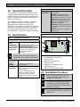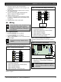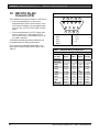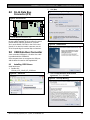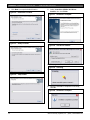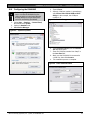
1
DX4010V2
Installation Instructions
EN
RS-232/USB Serial
Interface Module
DX4010V2 | Installation Instructions | Trademarks
Trademarks
•
2
BlackBox® is either a registered trademark or a
trademark of BlackBox Corporation in the United
States and/or other countries.
Bosch Security Systems, Inc. | 9/08 | F01U083036-01
DX4010V2 | Installation Instructions | Contents
Contents
1.0
2.0
3.0
4.0
5.0
5.1
5.2
5.3
6.0
7.0
8.0
9.0
9.1
General Information ....................................4
Specifications ..............................................4
Installation Standards .................................4
Wiring........................................................... 5
DX4010V2 Jumper Pin Settings ................ 6
Enable LED Jumper Pins (P2) ..................... 6
DB9 Ground Enable Pins (P1) ..................... 6
Address DIP Switches.................................. 7
Remote Programming Direct Connection 7
DB9 DTE RS-232 Connector (P6) ............ 10
RJ-16 Data Bus Connector (P3) .............. 11
USB Data Bus Connector ........................ 11
Installing USB Drivers ................................ 11
Figures
Figure 1:
Figure 2:
Figure 3:
Figure 4:
Figure 5:
Figure 6:
Figure 7:
Figure 8:
Figure 9:
Figure 10:
Figure 11:
Figure 12:
Figure 13:
Figure 14:
Figure 15:
Figure 16:
Figure 17:
Figure 18:
Figure 19:
Figure 20:
Figure 21:
Figure 22:
Figure 23:
DX4010V2 Component Layout .............. 4
Control Panel Connections .................... 5
External Power Supply Connections...... 5
Serial Device Connections..................... 5
Parallel Device Connections .................. 6
P2 Jumper Settings ............................... 6
DIP Switch Location and Orientation ..... 7
DB9 Connector Layout ........................ 10
P3 Connector....................................... 11
Select File ............................................ 11
Security Warning ................................. 11
Install Shield ........................................ 11
Security Warning ................................. 11
Destination Location ............................ 12
Ready to Install .................................... 12
Setup Status ........................................ 12
Installation Complete ........................... 12
USB Driver Installer ............................. 12
Scanning.............................................. 12
Installation Complete ........................... 12
System Properties ............................... 13
Device Manager................................... 13
Panel Communication.......................... 13
Tables
Table 1:
Table 2:
Table 3:
Table 4:
Table 5:
DX4010V2 Specifications ...................... 4
Diagnostic LED Functions ..................... 6
Option Bus Address DIP Switch Settings8
SDI Bus Address DIP Switch Settings ... 9
Alternate Wiring Configuration ............. 10
Bosch Security Systems, Inc. | 9/08 | F01U083036-01
3
DX4010V2 | Installation Instructions | 1.0
General Information
1.0 General Information
The DX4010V2 is a data terminal equipment (DTE)
configured RS-232/USB serial device interface. This
module is designed to operate with compatible control
panels. It connects to the control panel through the
Option or SDI data bus.
Table 1: DX4010V2 Specifications (continued)
Application
Compatibility
The DX4010V2 is used to connect a PC with RPS,
BIS, PC 9000, CMS 7000, or other third party
software that uses a serial connection to the
supported control panels. The module also supports a
serial printer (or parallel printer with a converter box)
for control panels that support a serial printer. The
compatibility lists in Table 1 show support information.
2.0 Specifications
RPS: Supported on all compatible
control panels.
PC 9000: Supported on SDI Bus
control panels (D9412G, D7412G,
D7212G, D9112, D7412, and D7212).
BIS: Supported on SDI Bus control
panels, v6.3 and higher (D9412GV2,
D7412GV2, D7212GV2, D9412G,
D7412G, and D7212G).
CMS 7000: Supported on DS7400Xi
Control Panels set at Mode 18 (v3.09
or higher).
Printers: Supported on compatible
control panel.
Figure 1: DX4010V2 Component Layout
Table 1: DX4010V2 Specifications
5
6
LED
Operating
Voltage
Current Draw
Communication
Configuration
12 VDC nominal
55 mA nominal, 60 mA with
diagnostic LEDs enabled
Programmable through the control
panel. Refer to the appropriate
control panel programming
instructions.
The baud rate for the printer output on a
DS7400Xi must be greater than 300 baud.
Operating
Temperature
Relative
Humidity
Control Panel
Compatibility
0°C to +50°C (+32°F to +122°F)
5 to 85% @ +30°C (+86°F)
non-condensing
Option bus control panels: D6412,
D4412, DS7240, DS7220, DS7400Xi
(v2.02 or higher)
SDI bus control panels (v6.0 or
higher): D9412GV2, D7412GV2,
D7212GV2, D9412G, D7412G,
D7212G, D9124, D9112, D7412, and
D7212
Rx Tx
BUS
4
7
Tx Rx
SER
8
3
2
P1
DB9 GND
ENABLE
P3
1
12345678-
DB9 GND enable pins (P1)
RJ-16 data bus connector (P3)
Data bus (TS1)
Address DIP switches (S1)
Diagnostic LEDs
Diagnostic LED enable pins (P2)
USB Connector (P7)
DB9 DTE RS-232 connector (P6)
3.0 Installation Procedure
Failure to follow the instructions in this
manual can result in personal injury or
damage to the equipment.
The DX4010V2 contains static-sensitive
components and must be handled with
care. Follow anti-static procedures when
handling the modules.
Test according to NFPA 72 if used in fire
applications.
4
Bosch Security Systems, Inc. | 9/08 | F01U083036-01
DX4010V2 | Installation Instructions | 4.0
1. Disconnect power to the control panel by
unplugging the transformer and removing the red
battery lead.
2. Remove screws from enclosure cover to access
the DX4010V2 board.
3. Connect circuit wiring and install jumper pins.
Refer to Section 4.0 Wiring on page 5.
4. Replace enclosure cover.
5. Connect a serial cable to the serial device. Refer
to Section 7.0 DB9 DTE RS-232 Connector (P6)
on page 10.
6. Reapply power to the control panel.
Figure 3: External Power Supply Connections
1
2
3
4
5
6
4.0 Wiring
+
Remove all power to the control panel (AC
and standby battery) before making or
breaking any connections. Failure to do so
can result in personal injury or damage to
the equipment.
Wire Length Restrictions
•
0.8 mm (#22 AWG): 305 m (1000 ft)
•
1.2 mm (#18 AWG): 610 m (2000 ft)
•
USB or Serial Cables are not to exceed 2 meters
(6 ft) in length.
SDI option bus wiring is limited to 305 m
(1000 ft).
Wiring
-
7
1234567-
DX4010V2 data bus
Control panel data bus
Option AUX common/SDI common (black)
Option data/SDI B (green)
Option data/SDI A (yellow)
Option AUX power +/SDI power (red)
External 12 VDC power supply
Figure 4 shows serial device-to-DX4010V2
connections using the DB9 DTE RS-232 connector
(P6).
Figure 4: Serial Device Connections
Connect the DX4010V2 to the control panel data and
auxiliary power sources as shown in Figure 2.
LED
Rx Tx
BUS
Tx Rx
SER
P2
Figure 2: Control Panel Connections
2
1
B
123456-
3
P1
G
4
Y
5
R
6
DX4010V2 data bus
Control panel data bus
Option AUX common/SDI common (black)
Option data/SDI B (green)
Option data/SDI A (yellow)
Option AUX power +/SDI power (red)
DB9 GND
ENABLE
P3
1
1- Serial (RS-232) device such as a PC (with
RPS, BIS, PC9000, or other third party
application) or a serial printer for supported
control panels.
Refer to Section 7.0 DB9 DTE RS-232
Connector (P6) on page 10 for additional
information.
If an external 12 VDC power supply is used, wire as
shown in Figure 3.
Bosch Security Systems, Inc. | 9/08 | F01U083036-01
5
DX4010V2 | Installation Instructions | 5.0
DX4010V2 Jumper Pin Settings
Figure 5 shows a parallel printer connected to the
serial output of the DX4010V2. This type of
connection requires the use of a serial to parallel
converter, such as the BlackBox PI045A serial to
Centronics parallel converter cable. The cable is
available from BlackBox® (www.blackbox.com).
Figure 6: P2 Jumper Settings
2
LED
Rx Tx
BUS
Tx Rx
SER
P2
Figure 5: Parallel Device Connections
LED
Rx Tx
BUS
Tx Rx
SER
P2
P1
DB9 GND
ENABLE
P3
1
P1
DB9 GND
ENABLE
P3
3
2
1
Printers are not supported on the USB
bus.
1- Parallel converter cable box (BlackBox P/N:
PI045A
2- Parallel printer (compatible option bus control
panels only)
5.0 DX4010V2 Jumper Pin
Settings
5.1
Enable LED Jumper Pins (P2)
Use the diagnostic LEDs for troubleshooting. To
enable the LEDs, place a jumper plug across the
jumper pins labeled P2.
Refer to Figure 6 for jumper pin settings.
The DX4010V2 draws more current when
the diagnostic LEDs are enabled. Do not
enable the diagnostic LEDs under normal
operating conditions.
1234-
4
DB9 GND enable pins (P1)
Diagnostic LED enable pins (P2)
Disabled
Enabled
Table 2: Diagnostic LED Functions
Diagnostic
LED
BUS RX
BUS TX
SER RX
SER TX
5.2
Function
Data bus receives data from control
panel
Data bus transmits data to control
panel
RS-232 receives data from serial
device
RS-232 transmits data to serial device
DB9 Ground Enable Pins (P1)
Some devices connected to the DB9 DTE RS-232
connector (P6) can cause a ground fault condition on
the control panel. If this occurs, removing the plug
across the P1 jumper pins clears the ground fault
condition.
Some devices might still cause a ground
fault even if the P1 jumper plug is
removed.
Refer to Figure 6 for jumper pin settings.
6
Bosch Security Systems, Inc. | 9/08 | F01U083036-01
DX4010V2 | Installation Instructions | 6.0
5.3
Address DIP Switches
The address DIP switches are used to assign an
address to the DX4010V2.
Refer to Table 3 on page 8 for DIP switch option bus
address settings.
Refer to Table 4 on page 9 for DIP switch SDI bus
address settings.
Refer to Figure 7 for proper DIP switch orientation.
Figure 7: DIP Switch Location and Orientation
LED
Rx Tx
BUS
1
Tx Rx
SER
Remote Programming Direct Connection
6.0 Remote Programming
Direct Connection
The DX4010V2 can be used to create a local direct
connection for remote programming of a compatible
control panel.
Option Bus: Set the address DIP switches to
Address 0. Refer to Table 3 on page 8.
SDI Bus: Set the address DIP switches to Address
88. Refer to Table 4 on page 9.
Consult your control panel’s installation guide for
specific wiring connections.
P2
A DB9 to DB9 null-modem cable is
required when using the direct
connection method.
P1
DB9 GND
ENABLE
P3
ON
3
1
2
3
4
5
6
1
2
4
8
16
32
7
4
8
64 128
2
1234-
Address DIP switches
Address example (option bus Address 0)
OFF position
ON position
Bosch Security Systems, Inc. | 9/08 | F01U083036-01
7
DX4010V2 | Installation Instructions | 6.0
Remote Programming Direct Connection
Table 3: Option Bus Address DIP Switch Settings
Some automation software packages might require that you restart the application if USB
connection is lost during use.
DIP Switch Settings
DIP
Switches
Module
Address
S1
S2
S3
S4
S5
S6
S7
S8
1
2
4
8
16
0*
1
2
3
4
5
6
7
8
9
10
11
12
13**
14**
15
134
135
136
137
138
139
140
141
142
143
144
145
250
251
252
253
ON
OFF
ON
OFF
ON
OFF
ON
OFF
ON
OFF
ON
OFF
ON
OFF
ON
OFF
ON
OFF
ON
OFF
ON
OFF
ON
OFF
ON
OFF
ON
OFF
ON
OFF
ON
OFF
ON
ON
OFF
OFF
ON
ON
OFF
OFF
ON
ON
OFF
OFF
ON
ON
OFF
OFF
ON
ON
OFF
OFF
ON
ON
OFF
OFF
ON
ON
OFF
OFF
ON
ON
OFF
OFF
ON
ON
ON
ON
OFF
OFF
OFF
OFF
ON
ON
ON
ON
OFF
OFF
OFF
OFF
OFF
OFF
OFF
OFF
ON
ON
ON
ON
OFF
OFF
OFF
OFF
ON
ON
ON
ON
ON
ON
ON
ON
ON
ON
ON
ON
OFF
OFF
OFF
OFF
OFF
OFF
OFF
OFF
ON
ON
ON
ON
OFF
OFF
OFF
OFF
OFF
OFF
OFF
OFF
ON
ON
ON
ON
ON
ON
ON
ON
ON
ON
ON
ON
ON
ON
ON
ON
ON
ON
ON
ON
ON
ON
ON
ON
ON
ON
ON
ON
ON
ON
ON
ON
ON
ON
ON
ON
32
(Mode)
OFF
OFF
OFF
OFF
OFF
OFF
OFF
OFF
OFF
OFF
OFF
OFF
OFF
OFF
OFF
OFF
ON
ON
ON
ON
ON
ON
ON
ON
ON
ON
ON
ON
ON
ON
ON
ON
64
(Option/SDI)
ON
ON
ON
ON
ON
ON
ON
ON
ON
ON
ON
ON
ON
ON
ON
ON
ON
ON
ON
ON
ON
ON
ON
ON
ON
ON
ON
ON
ON
ON
ON
ON
128
(Checksum +1)
OFF
OFF
OFF
OFF
OFF
OFF
OFF
OFF
OFF
OFF
OFF
OFF
OFF
OFF
OFF
OFF
ON
ON
ON
ON
ON
ON
ON
ON
ON
ON
ON
ON
ON
ON
ON
ON
* Installer’s mode: Use for direct connection of remote programming and diagnostic tools.
** DS7412 emulation
The DS7400Xi (USA) only supports one DX4010V2.
Option bus control panels: D6412, D4412, DS7240, DS7220, DS7400Xi (v2.02 or higher).
8
Bosch Security Systems, Inc. | 9/08 | F01U083036-01
DX4010V2 | Installation Instructions | 6.0
Remote Programming Direct Connection
Table 4: SDI Bus Address DIP Switch Settings
SDI DIP Switch Settings
SDI DIP
Switches
Module
Address
S1
S2
S3
S4
S5
S6
S7
S8
1
2
4
8
16
80*
81
82
83
84
85
86
87
88**
89
8A
8B
8C
8D
8E
8F
ON
OFF
ON
OFF
ON
OFF
ON
OFF
ON
OFF
ON
OFF
ON
OFF
ON
OFF
ON
ON
OFF
OFF
ON
ON
OFF
OFF
ON
ON
OFF
OFF
ON
ON
OFF
OFF
ON
ON
ON
ON
OFF
OFF
OFF
OFF
ON
ON
ON
ON
OFF
OFF
OFF
OFF
ON
ON
ON
ON
ON
ON
ON
ON
OFF
OFF
OFF
OFF
OFF
OFF
OFF
OFF
OFF
OFF
OFF
OFF
OFF
OFF
OFF
OFF
OFF
OFF
OFF
OFF
OFF
OFF
OFF
OFF
32
(Mode)
OFF
OFF
OFF
OFF
OFF
OFF
OFF
OFF
OFF
OFF
OFF
OFF
OFF
OFF
OFF
OFF
64
(Option/SDI)
OFF
OFF
OFF
OFF
OFF
OFF
OFF
OFF
OFF
OFF
OFF
OFF
OFF
OFF
OFF
OFF
128
(Checksum +1)
OFF
OFF
OFF
OFF
OFF
OFF
OFF
OFF
OFF
OFF
OFF
OFF
OFF
OFF
OFF
OFF
Positions 5, 6, and 8 are not used for SDI bus.
* Used for BIS, PC 9000, and other third party applications.
** Used for RPS and alternate communication.
SDI bus control panels (v6.0 or higher): D9412GV2, D7412GV2, D7212GV2, D9412G, D7412G,
D7212G, D9124, D9112, D7412, and D7212.
Bosch Security Systems, Inc. | 9/08 | F01U083036-01
9
DX4010V2 | Installation Instructions | 7.0
DB9 DTE RS-232 Connector (P6)
7.0 DB9 DTE RS-232
Connector (P6)
Figure 8: DB9 Connector Layout
1
The DX4010V2 serial port is wired as a DTE device.
•
If the connected device is a data carrier
equipment (DCE) device (most common, such
as an external modem), use a straight through
9-pin to 9-pin, or (DTE to DCE) 9-pin to 25-pin
cable.
•
If the connected device is a DTE device (such
as a PC serial port), a null-modem (DTE to
DTE) 9-pin to 9-pin, or null-modem 9-pin to 25pin cable is required.
Consult the operating manual provided with your
compatible device for wiring requirements.
If you are using an alternate configuration, you
must make a custom cable (refer to Figure 8 and
Table 5).
10
2
6
12345-
DCD
RxD
TxD
DTR
GND
3
7
4
5
8
9
6789-
DSR
RTS
CTS
RI
Table 5: Alternate Wiring Configuration
DX4010V2
9-Pin DTE
Connector
1: DCD
(not used)
2: RxD
3: TxD
4: DTR
DCE
(9-pin)
DTE
(9-pin)
DCE
(25-pin)
DTE
(25-pin)
1: DCD
1: DCD
8: DCD
8: DCD
2: RxD
3: TxD
4: DTR
3: TxD
2: RxD
6: DSR
3: RxD
2: TxD
2: TxD
3: RxD
6: DSR
5: GND
6: DSR
7: RTS
8: CTS
9: RI
(not used)
5: GND
6: DSR
7: RTS
8: CTS
9: RI
5: GND
4: DTR
8: CTS
7: RTS
9: RI
20:
DTR
7: GND
6: DSR
4: RTS
5: CTS
22: RI
7: GND
20: DTR
5: CTS
4: RTS
22: RI
Bosch Security Systems, Inc. | 9/08 | F01U083036-01
DX4010V2 | Installation Instructions | 8.0
RJ-16 Data Bus Connector (P3)
2. Click Run.
Figure 11: Security Warning
8.0 RJ-16 Data Bus
Connector (P3)
Figure 9: P3 Connector
LED
Rx Tx
BUS
Tx Rx
SER
1
P2
P1
P3
DB9 GND
ENABLE
1- RJ-16 data bus connector (P3)
For remote programming connection, use one of
the two cables supplied: RJ-16 to molex for control
panels with the data bus provided on a header
(such as the D6412, DS7240, or the GV2 control
panels). If no data bus header is present, use the
RJ-16 to spade lugs for terminal strip connections.
3. Click Next to continue.
Figure 12: Install Shield
9.0 USB Data Bus Connector
Uses a standard USB type A→B cable. One cable
is provided with the DX4010V2.
If the computer does not recognize the USB port,
add the drivers located on the supplied disk.
9.1
Installing USB Drivers
Install the drivers.
1. Double-click
CP210x_VCP_Win2K_XP_S2K3.exe.
2
Figure 10: Select File
4. Click I accept the terms of the license
agreement. Then click Next.
Figure 13: Security Warning
Bosch Security Systems, Inc. | 9/08 | F01U083036-01
11
DX4010V2 | Installation Instructions | 9.0
5. Click Next to accept the default location.
Figure 14: Destination Location
USB Data Bus Connector
8. Select Launch the CP210x VCP Driver
Installer, then click Finish.
Figure 17: Installation Complete
6. Click Install.
Figure 15: Ready to Install
9. Click Install.
Figure 18: USB Driver Installer
10. The program will look for the file location.
Figure 19: Scanning
7. The drivers install.
Figure 16: Setup Status
11. When the installation completes successfully,
click OK.
Figure 20: Installation Complete
12
Bosch Security Systems, Inc. | 9/08 | F01U083036-01
DX4010V2 | Installation Instructions | 9.0
10.0
Configuring the DX4010V2
Before configuring the DX4010V2, be
sure to connect the DX4010V2 to the
USB port and the control panel. Be sure
that the address is correct and that the
red LEDs are flashing (if enabled).
USB Data Bus Connector
4. Expand Ports.
5. Note the COM port number, in parentheses,
after Silicon Labs CP210x USB to UART
Bridge. In this example, the COM port
number is 3.
Figure 22: Device Manager
1. Select Start → Settings → Control Panel,
then double-click System.
2. Select the Hardware tab.
3. Click Device Manager.
Figure 21: System Properties
6. Select Enhanced Direct from the Connect
Via drop down menu.
7. Enter the COM Port number from Step 5 in
the Com Port field.
8. Make sure the DX4010V2 is connected to
a USB Port, then click Connect.
9. The installation process is complete.
Figure 23: Panel Communication
Bosch Security Systems, Inc. | 9/08 | F01U083036-01
13
Bosch Security Systems, Inc.
130 Perinton Parkway
Fairport, NY 14450-9199
(800) 289-0096
© 2008 Bosch Security Systems, Inc.
F01U083036-01