1
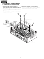
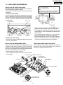
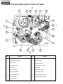
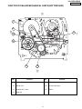
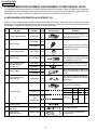
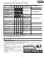
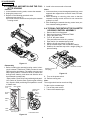
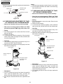
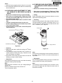
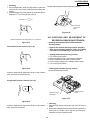
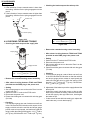
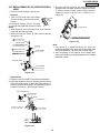
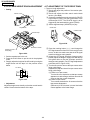
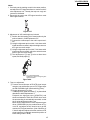
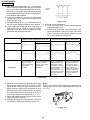
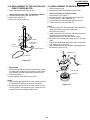
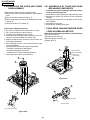
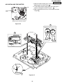
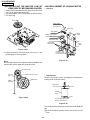
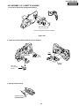
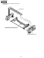
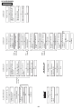
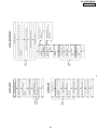
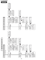
VC-A565U/H965U
SUPPLEMENT
SERVICE MANUAL
S62K8VC-A565U
SUPPLEMENT
VIDEO CASSETTE RECORDER
VC-A565U
MODELS
VC-H965U
VC-A565U
VC-H965U
In the interests of user-safety (Required by safety regulations in some countries) the set should be restored to its
original condition and only parts identical to those specified be used.
OUTLINE
This Supplement describes corrections of the mechanism in the VC-A565U/H965U Service Manual already
issued. For the items which are not described in this Supplement, refer to the VC-A565U/H965U Service Manual
(S32G5VC-A565U).
CONTENTS
2.
3.
4.
6.
Page
DISASSEMBLY AND REASSEMBLY ........................................................................................... 2
FUNCTION OF MAJOR MECHANICAL PARTS ........................................................................... 4
ADJUSTMENT, REPLACEMENT AND ASSEMBLY OF MECHANICAL UNITS .......................... 6
MECHANISM OPERATION FLOWCHART AND TROUBLESHOOTING GUIDE ...................... 25
VC-A565U/H965U ............................ Models for U.S.A/CANADA
SHARP CORPORATION
This document has been published to be used for
after sales service only.
1 The contents are subject to change without notice.
VC-A565U/H965U
SUPPLEMENT
2. DISASSEMBLY AND REASSEMBLY
2-2 DISASSEMBLING THE MECHANISM
2. Removing the mechanism and cassette housing.
1. When removing the mechanism from the set.
Remove 2 screws 3 fixing the cassette housing to the
Remove the screw 2 which connecting the PWB and
mechanism, and remove the cassette housing.
the mechanism.
Remove the screw 4 which connecting mechanism and
main frame.
Take out vertically the mechanism so that it does not
damage the adjacent parts.
4
3
MECHANISM CHASSIS
CASSETTE
HOUSING
2
VC-A565U
VC-H965U
MAIN FRAME
2
VC-A565U/H965U
SUPPLEMENT
2-3 CARES WHEN REASSEMBLING
Rotate the flange of worm gear by using thin stick.
CW • • • Loading direction
CCW • • • Ejection direction
Note
Be careful not to damage the gear of worm gear and
worm wheel gear. It might cause a strange sound.
INSTALLING THE CASSETTE HOUSING
When the cassette housing is installed on the mechanism,
the initial setting is essential condition.
There are two initial setting methods, namely electrical and
mechanical.
1. Electrical initial setting
So as to perform initial setting of mechanism execute the
Step 1 of Installation of cassette housing. After ascertaining
the return to the initial setting position install the cassette
housing. (Conditions: When mechanism and PWB have
been installed)
Main Chassis
Pinch Drive Cam
Synchro Gear
• When apply power supply to rotate the loading motor,
please remove/unsolder at least one terminal wire.
• If voltage applied to loading motor without disconnecting
the terminal wire, there is a possibility the capstan motor
IC will damage.
• The maximum applied voltage is 9V. If more than 9V,
there is a possibility the mechanism will damage.
• After ascertaining the return to the initial set position
install the cassette housing in the specified position.
(This method is applied only for the mechanism.)
Drive Lever
Master cam
2. Mechanical initial setting
• Rotate the worm gear by pushing the flange manually until
return to initial position.
PARTS WHICH NEED PARTICULAR CARE
When installing the mechanism chassis on the PWB unit,
take care so as to prevent deformation due to contact of
mechanism chassis with REC TIP SW.
INSTALLING THE MECHANISM ON PWB
Lower vertically the mechanism, paying attention to the
mechanism edge mode SW position, (Set the mode SW
position to 270° and make sure the master cam position
hole also in 270° position) and install the mechanism with
due care so that the parts are not damaged.
* Please make sure to insert correctly.
If not, strange moving will occur and will couse mechanism damage.
END SENSOR
AE CONNECTOR
AH CONNECTOR
AA CONNECTOR
AD CONNECTOR
AC CORD
VC-A565U
VC-H965U
START SENSOR
END TIP SW
90°
0°
180°
This positioning hole
should be at front side.
MASTER CAM POSITION
3
270°
MODE SW
VC-A565U/H965U
SUPPLEMENT
3. FUNCTION OF MAJOR MECHANICAL PARTS (TOP VIEW)
17
15
18
26
10
16
14
1
9
2
11
3
5
7
8
6
No.
4
12
Function
13
No.
Function
1
Full erase head
11
Reverse guide lever ass’y
2
Supply pole base ass’y
12
Reel relay gear
3
Tension arm
13
Take-up reel disk
4
Idler wheel ass’y
14
Pinch roller lever ass’y
5
Open guide
15
Drum ass'y
6
Supply reel disk
16
Loading motor block
7
Supply main brake
17
Drum driver motor
8
Take-up main brake
18
Take-up pole base ass'y
9
Pinch drive cam
26
Auto head cleaner Ass'y
10
A/C head ass’y
4
VC-A565U/H965U
SUPPLEMENT
FUNCTION OF MAJOR MECHANICAL PARTS (BOTTOM VIEW)
21
22
25
19
20
23
No.
24
Function
No.
Function
19
Syncro Gear
23
Clutch lever
20
Master cam
24
Limiter pulley ass’y
21
Capstan D.D. motor
25
Shifter
22
Reel belt
5
VC-A565U/H965U
SUPPLEMENT
4. ADJUSTMENT, REPLACEMENT AND ASSEMBLY OF MECHANICAL UNITS
The explanation given below relates to the on-site general service (field service) but it does not relates to the adjustment
and replacement which need high-grade equipment, jigs and skill. For example, the drum assembling, replacement and
adjustment service must be performed by the person who have finished the technical courses.
4-1 MECHANISM CONFIRMATION ADJUSTMENT JIG
So as to perform completely the mechanism adjustment prepare the following special jigs. So as to maintain the initial
performance of the machine the maintenance and check are necessary. Utmost care must be taken so that the tape is
not damaged. If adjustment needs any jig, be sure to use the required jig.
No.
Jig ltem
Part No.
Code
1.
Torque Cassette Meter
JiGVHT-063
CZ
JiGTG0090
CM
2.
Torque Gauge
JiGTG1200
CN
3.
Torque Gauge Head
JiGTH0006
AW
4.
Torque Driver
JiGTD1200
CB
Master Plane Jig and
Reel Disk Height
Adjusting Jig
JiGRH0002
BR
5.
JiGMP0001
BY
JiGSG2000
BS
JiGSG0300
BF
JiGADP003
BK
6.
7.
Configuration
This cassette torque meter is used for checking and adjusting the torque of take-up for
measuring tape back tension.
These Jigs are used for checking
and adjusting the torque of take-up
and supply reel disks.
When fixing any part to the threaded
hole using resin with screw, use the
jig. (Specified torque 5 kg)
These Jigs are used for checking
and adjusting the reel disk height.
There are two gauges used for the
tension measurements, 300 g and
2.0 kg.
Tension Gauge
Pinch pressing force
measuring jig
Remarks
This Jig is used with the tension
gauge. Rotary transformer clearance
adjusting jig.
These tapes are especially used for
electrical fine adjustment.
Video
8.
9.
Alignment Tape
Guide roller height
adjustment driver
10.
X value adjustment
gear driver
11.
Tension Pole
Adjustment Driver
VROATSV
CD
VROEFZCS
OR
VROEFZHS
BG
HiFi Audio
Track
525 Monoscope
7k
—
58µm
NTSC Color Bar
1k
—
58µm
—
19µm
Black Level
(only SYNC) signal
BH
1k
2.3k
This screwdriver is used for adjusting the
guide roller height.
JiGDRiVERH-4 AP
JiGDRiVER-6
Audio
For X value adjustment
BM
This Jig is used for adjustment
of tension pole.
JiGHMEC-M005 CK
6
VC-A565U/H965U
SUPPLEMENT
4-2 MAINTENANCE CHECK ITEMS AND EXECUTION TIME
Perform the maintenance with the regular intervals as follows so as to maintain the quality of machine.
Maintained 500 1000 1500 2000 Possible symptom
Remarks
encountered
hrs. hrs. hrs. hrs.
Parts
Abnormal rotation or significant
Guide roller ass’y
vibration requires replacement.
Sup guide shaft
Reverse guide
Lateral noises Head
occasionally blocked
Clean tape contact part with the
specified cleaning liquid.
Slant pole on pole base
Full erase head
A/C head
Upper and lower drum ass’y
Capstan D.D. motor
Pinch roller
Reel belt
Colour and beating
Small sound or sound
distortion
Poor S/N ratio, no colour
Poor flatness of the
envelope with alignment
tape
No tape running,
uneven colour
No tape running, tape
slack
No tape running, tape
slack, no fast forward/
rewind motion
Tension band ass’y
Screen swaying
Loading motor
Cassette not loaded or
unloaded
Idler ass’y
Limiter pulley
Supply/take-up main brake levers
Clean tape contact area with the
specified cleaning liquid.
Clean rubber and rubber contact
area with the specified cleaning
liquid.
No tape running, tape
slack
Tape slack
NOTE
: Part replacement.
: Cleaning
: Apply grease
<Specified> Cleaning liquid Industrial ethyl alcohol
* This mechanism does not need electric adjustment with variable resistor. Check parts. If any deviation is found,
clean or replace parts.
Video head cleaning procedure
1. Apply one drop of cleaning liquid to the cleaning paper with the baby oiler.
2. Gently press the cleaning paper against the video head to fix your finger, and move the upper drum so that each head
is passed to and fro 5 times (do not move the cleaning paper).
3. Wipe with the dry cleaning paper.
Rotate the upper drum
with one hand.
Notes :
• Use the commercially available ethanol of Class 1 as
cleaning liquid.
• Since the video head may be damaged, do not move up
and down the cleaning paper.
• Whenever the video head is cleaned, replace the cleaning paper.
• Do not apply this procedure for the parts other than the
video head.
Gently press the cleaning paper to
fix with your finger, and rotate the
upper drum to clean.
Move to and fro 5 times for each head.
(Do not move the cleaning paper.)
Parts Code
ZPAPRA56-001E
ZOiLR-02-24TE
7
Description
Cleaning Paper
Babe Oiler (Spoit)
Code
AW
AH
VC-A565U/H965U
SUPPLEMENT
4-3 REMOVING AND INSTALLING THE CASSETTE HOUSING
2. Install in the reverse order of removal.
• Removal
1. In the cassette removing mode, remove the cassette.
2. Unplug the power cord.
3. Remove in the following numerical order.
a) Remove two screws 1.
b) Pull and circle the drive lever and pull up the cassette
housing control.
Notes
1. In the case when you use the magnet screw driver, never
approach the magnet driver to the A/C head, FE head,
and drum.
2. When installing or removing, take care so that the
cassette housing control and tool do not contact the
guide pin or drum.
3. After installing the cassette housing control once perform cassette loading operation.
1
4-4 TO RUN A TAPE WITHOUT THE CASSETTE
HOUSING CONTROL ASSEMBLY
1.
2.
3.
4.
5.
6.
7.
8.
Remove the full-surface panel.
Short-circuit between TP803 and TP802.
Plug in the power cord.
Turn off the power switch.
(The pole bases move into U.L.position.)
Open the lid of a cassette tape by hand.
Hold the lid with two pieces of vinyl tape.
Set the cassette tape in the mechanism chassis.
Stabilize the cassette tape with a weight (500g) to
prevent floating.
500g
Figure 4-1.
• Reassembly
1. Before installing the cassette housing control, shortcircuit between TP803 and TP802 provided at main
PWB, press the eject button. The master cam turns and
stop in eject position. Fit the drive lever to master cam
through main chassis, push down and slide the drive
lever towards to master cam.
*Eject position: Pinch Drive Cam positioning hole parallel to center of Synchro Gear (Synchro gear marking
line). Synchro Gear positioning mark parallel to center
of master cam.
Pinch Drive
Cam
Hole of Pinch
drive cam.
Phase
matching
Master
cam
Line of
synchro
gear.
Master cam
Drive
Lever
From top view
Figure 4-3.
9. Turn on the power switch.
10. Perform running test.
Note:
The weight should not be more than 500g.
To take out the cassette tape.
1. Turn off the power switch.
2. Take out the cassette tape.
Main chassis
Synchro
Gear
Mechanism chassis
Weight to prevent
float (500g)
From Bottom View
Figure 4-2.
8
VC-A565U/H965U
SUPPLEMENT
4-5 REEL DISK REPLACEMENT AND HEIGHT
CHECK
• Removal
1. Remove the cassette housing control assembly.
2. Remove the Supply/Take-up main brake ass'y.
3. Remove tension band from the tension arm ass'y.
4. Remove the reel disk.
Note:
Take care so that the tension band ass'y and main brake
ass'y are not deformed.
Tension
Take-up main brake ass'y
Ten arm ass'y
Supply main brake
Tension band
ass'y
Supply reel disk
Take-up reel disk
Notes:
1. When installing the reel disk, take due care so that the
tension band ass'y is not deformed and grease does no
adhere.
2. Do not damage the Supply main brake ass'y. Be careful
so that grease does not adhere to the brake surface.
• Reassembly (Take-up reel disk)
1. Clean the reel disk shaft and apply grease (SC-141) to
it.
2. Align the phase of the reel disk to that of the reel relay
gear and to install a new take-up reel disk onto the shaft.
3. Check the reel disk height and reassemble the take-up
main brake ass'y.
Note:
1. Take care so that the Take-up main brake ass'y is not
damaged. Take care so that grease does not adhere the
brake surface.
2. After reassembly, check the video search rewind back
tension (see 4-10), and check the brake torque (see 414).
• Height checking and adjustment
Note:
1. Set the master plane with due care so that it does not
contact the drum.
2. When putting the master plane, shift the reverse guide
a little in the loading direction. Care must be taken since
excessive shift results in damage.
• Reassembly (Supply reel disk)
1. Clean the reel disk shaft and apply grease (SC-141) to
it.
2. Match the phases of reel disk and reel relay gear, and set
the new reel disk.
3. After checking the reel disk height, wind the tension
band ass'y around the reel disk, and hook to tension arm
ass'y.
4. Assemble the Supply main brake ass'y.
Master plane
Supply reel disk
Cassette lock
release shaft
Take-up reel disk
Figure 4-4.
Note:
• Check that the reel disk is lower than part A but higher
than part B. If the height is not correct, readjust the reel
disk height by changing the poly-slider washer under the
reel disk.
9
VC-A565U/H965U
SUPPLEMENT
Note:
Whenever replacing the reel disk, perform the height checking and adjustment.
Reel disk height
adjusting jig
Master plane
10 ± 0.2mm
4-7 CHECKING AND ADJUSTMENT OF TAKEUP TORQUE IN REWIND MODE
Mechanism chassis
Reel disk
Notes:
1. Hold the torque gauge by hand so that it is not moved.
2. Do not keep the reel disk in lock state. Do not allow longtime measurement.
• Remove the cassette housing control assembly.
A
B
• After short-circuiting between TP803 and TP802
provided at operation PWB, plug in the power cord.
Reel disk
Figure 4-5.
4-6 CHECKING AND ADJUSTMENT OF TAKEUP TORQUE IN FAST FORWARD MODE
• Remove the cassette housing control assembly.
• After short-circuiting between TP803 and TP802
provided at operation PWB, plug in the power cord.
• Setting
1. Set a torque gauge to zero on the scale. Place it on the
take-up reel disk.
2. Press the FF button.
3. To calculate the remaining capacity of the play back
mode, slowly rotate the supply reel disk, and then shift
it into the forward mode.
• Checking
1. Turn the torque gauge slowly (one rotation every 2 to 3
seconds) by hand in the CW direction.
2. Make sure that the indication of torque gauge is not less
than 25mN·m (255gf·cm).
Torque gauge
• Setting
1. Set a torque gauge to zero on the scale. Place it on the
supply reel disk.
2. Press the rewind button.
3. To calculate the remaining capacity, slowly rotate the
take-up reel disk, and then shift it into the rewind mode.
• Checking
1. Turn the torque gauge slowly (one rotation every 2 to 3
seconds) by hand in the CCW direction.
2. Make sure that the indication of torque gauge is not less
than 25mN·m (255gf·cm).
Torque gauge
25mN·m (255gf·cm)
or more
CCW
The gauge is held at
its maximum value.
(Red mark)
Supply reel disk
CW
25mN·m (255gf·cm)
or more
The gauge is held at
its maximum value.
(Red mark)
Idler ass'y
Figure 4-7.
Idler ass'y
Figure 4-6.
• Adjustment
1. If the FF winding-up torque is less than the specified
value, clean the capstan D.D. pulley, reel belt, and
limiter pulley with cleaning liquid, and check again.
2. If the torque is less than the set value, replace the reel
belt.
10
• Adjustment
1. If the rewind winding-up torque is less than the specified
value, clean the capstan D.D. pulley, reel belt, and
limiter pulley with cleaning liquid, rewind again, and
check the winding-up torque.
2. If the winding-up torque is still out of range, replace the
drive belt.
VC-A565U/H965U
SUPPLEMENT
Notes:
1. Hold the torque gauge by hand so that it is not moved.
2. Do not keep the reel disk in lock state. Do not allow longtime measurement.
4-9 CHECKING AND ADJUSTMENT OF TAKEUP TORQUE IN VIDEO SEARCH REWIND
MODE
4-8 CHECKING AND ADJUSTMENT OF TAKEUP TORQUE IN RECORD/PLAYBACK
MODE
• After short-circuiting between TP803 and TP802
provided at operation PWB, plug in the power cord.
• Remove the cassette housing control assembly.
• After short-circuiting between TP803 and TP802
provided at operation PWB, plug in the power cord.
• Turn off the power switch.
• Open the cassette torque meter lid, and fix it with
tape.
• Load the cassette torque meter into the unit.
• Put the weight (500g) on the cassette torque meter.
• Turn on the power switch.
• Press the picture record button, and set EP picture
record mode (x3).
• Remove the cassette housing control assembly.
• Setting
Press the playback button and rewind button to set the
video search rewinding mode.
• Checking
Place the torque gauge on the supply reel disk, and turn it
counterclockwise very slowly (one rotation every 1 to 2
seconds) and check that the torque is within the set value
14.1 ± 3.5mN⋅m. (144 ± 35gf⋅cm)
Torque gauge
+20
Set value EP 6.9 +2.0
–2.5mN⋅m (70 –25gf⋅cm)
CCW
500g
Cassette torque meter
Supply reel disk
Figure 4-8.
• Checking
1. Make sure that value is within the setting 6.9 +2.0
–2.5 mN·m
(70+20
–25 gf·cm).
2. The winding-up torque fluctuates due to variation of
rotation torque of limiter pulley ass'y. Read the center
value of fluctuation as setting.
3. Set the EP record mode (x3) and make sure that the
winding-up torque is within setting.
• Adjustment
If the playback winding-up torque is not within the setting,
replace the limiter pulley assembly.
Note:
When the torque cassette is set, put a weight (500g) to
prevent rise.
When the cassette torque meter is taken out.
Turn off the power switch.
Figure 4-9.
Note:
Surely put the torque gauge on the reel disk to measure. If
the torque gauge is raised, accurate measurement is
impossible.
• Adjustment
If the rewinding playback winding-up torque is not within the
setting, replace the limiter pulley assembly.
Note:
The winding-up torque fluctuates due to variation of rotation torque of supply reel disk. Read the center value of
fluctuation as setting.
11
VC-A565U/H965U
SUPPLEMENT
4-10 CHECKING THE VIDEO SEARCH REWIND
BACK TENSION
• Remove the cassette housing control assembly.
• After short-circuiting between TP803 and TP802
provided at main PWB, plug in the power cord.
Tension gauge
900 - 1,200gf
Pinch roller
• Checking
1. After pressing the play button, press the rewind button,
and set the video search rewind mode.
2. Place the torque gauge on the take-up reel disk, and turn
it counterclockwise very slowly (one rotation every 2 to
3 seconds) and check that the torque is within the set
value 3.7 ± 1.5mN⋅m (38 ± 15gf⋅cm).
Capstan shaft
Tension gauge adapter
Figure 4-11.
Torque gauge
4-12 CHECKING AND ADJUSTMENT OF
TENSION POLE POSITION
CCW
* Checking can be perform with or without cassette
housing contorl.
Take-up reel disk
• Remove the cassette housing contorol assembly.
Figure 4-10.
Notes:
Set the torque gauge securely on the take-up reel disk.
If it is not secure, the measurement will be incorrect.
4-11 C H E C K I N G T H E P I N C H R O L L E R
PRESSURE
* Checking can be perform with or without cassette
housing contorl.
•
After short-circuiting between TP803 and TP802
provided at main PWB, plug in the power cord.
•
1.
2.
3.
4.
5.
6.
Setting (with cassette housing contorl)
Turn off the power switch.
Open the cassette tape (T-120), and fix with tape.
Set the cassette tape in loading state.
Put the weight (500g) on the cassette tape.
Turn on the power switch.
Make the adjustment with the beginning of a T-120 tape.
•
Setting (with cassette housing contorl)
1. Insert cassette tape (T-120)
2. Make the adjustment with the beginning of a T-120
tape.
• Remove the cassette housing control assembly.
(T-120)
• After short-circuiting between TP803 and TP802
provided at main PWB, plug in the power cord.
• Checking
Press the play button to set the playback mode.
1. Detach the pinch roller from the capstan shaft.
Do not separate excessively. Or the pinch lever and
pinch double action lever may disengage.
2. Engage the tension gauge adapter with the pinch roller
shaft, and pull in the arrow direction.
3. Gradually return the pinch roller, and measure the
pulling force when the pinch roller contacts the capstan
shaft.
4. Make sure that the measured value is within setting
change to 9.8 ± 2N (1.0 ± 0.2kgf).
500g
Weight to prevent
float (500g)
Figure 4-12.
12
VC-A565U/H965U
W
CC
CW
• Checking
1. Set a cassette tape, push the REC button to place the
unit in the SP record mode. Now check the tension pole
position.
2. Visually check to see if the position of the tension pole is
within the 0 +0.5
–0.2 mm from the left side line.
SUPPLEMENT
Tension pole adjustment driver adjusting direction
Standard A = 0
+ 0.5
mm
- 0.2
Tension pole
adjustment
driver
Figure 4-16.
A
Make the adjustment with the beginning of a T-120 tape.
Figure 4-13.
At left side from the reference line. (A).
4-13 CHECKING AND ADJUSTMENT OF
RECORD/PLAYBACK BACK TENSION
* Checking can be perform with or without cassette
housing contorl.
• Remove the cassette housing contorol assembly.
• After short-circuiting between TP803 and TP802
provided at main PWB, plug in the power cord.
•
1.
2.
3.
4.
5.
A
Figure 4-14.
Setting (with cassette housing contorl)
Turn off the power switch.
Open the cassette torque meter and fix with tape.
Set the cassette torque meter in loading state.
Put the weight (500g) on the cassette torque meter.
Turn on the power switch.
• Setting (with cassette housing contorl)
1. Insert cassette torque meter.
Insert the tension pole adjustment driver to main chassis
hole, and rotate counterclockwise.
At right side from the reference line. (A).
500g
Cassette torque
meter
Weight to prevent
float (500g)
A
Figure 4-17.
Figure 4-15.
Insert the tension pole adjustment driver to main chassis
hole, and rotate clockwise.
• Checking
1. Push the REC button to place the unit in the SP record
mode.
2. At this time ascertain that the back tension is within the
setting 3.9 to 5.5mN⋅m (40 to 56gf·cm) by seeing the
indication of torque cassette meter.
13
VC-A565U/H965U
SUPPLEMENT
• Adjustment
1. If the indication of torque cassette meter is lower than
the setting, shift the tension spring engagement to the
part A.
2. If the indication of torque cassette meter is higher than
the setting, shift the tension spring engagement to the
part B.
A
• Checking the brake torque at the take-up side
Torque gauge
Tension arm
B
CW
CCW
Take-up reel
disk
Tension spring
CCW: 4.41 ± +2.0
–1.5 mN⋅m (45 ±
CW:
4.12 ± +1.5
–1.2 mN⋅m (42 ±
Figure 4-18.
4-14 CHECKING THE BRAKE TORQUE
• Checking the brake torque at the supply side
+20 gf⋅cm)
–15
+15 gf⋅cm)
–12
Figure 4-20.
• Remove the cassette housing control assembly.
Torque gauge
CCW
• After short-circuiting between TP803 and TP802
provided at main PWB, plug in the power cord.
CW
•
1.
2.
3.
Setting
Switch from the FF mode to the STOP mode.
Disconnect the power cord.
Set a torque gauge to zero on the scale. Place it on the
take-up reel disk.
4. Please check Idler gear not contact with reel relay gear
(TU side)
Supply reel disk
CCW: 4.41 ± +2.0
mN⋅m (45 ± +20
gf⋅cm)
–1.5
–15
+1.5
CW:
4.12 ± –1.2 mN⋅m (42 ± +15 gf⋅cm)
–12
Figure 4-19.
• Remove the cassette housing control assembly.
• After short-circuiting between TP803 and TP802
provided at main PWB, plug in the power cord.
• Setting
1. Set a torque gauge to zero on the scale. Place it on the
supply reel disk.
2. Switch from the FF mode to the STOP mode.
3. Disconnect the power cord.
4. Please check Idler gear not contact with reel relay gear
(SU side)
• Checking
Turn the torque gauge at a rate of about one turn/2 sec
in the CW direction/CCW direction with respect to the
supply reel disk so that the reel disk and torque gauge
pointer rotate at equal speed, and make sure that the
value is within the setting (CW direction: 4.12 ± +1.5
–1.2 mN·m
+2.0
+20
(42+15
gf·cm);
CCW
direction:
4.41
mN·m
(45
15gf·cm).
–1.5
–15
–12
14
• Checking
1. Turn the torque gauge at a rate of about one turn/2 sec
in the CCW direction/CW direction so that the reel disk
and torque gauge pointer rotates at equal speed and
make sure that the value is within the setting (CCW
+2.0
direction: 4.41 –1.5
± 1mN·m (45 +20
± gf·cm), CW direction:
–15
+1.5
4.12 ±–1.21.mN·m (42 +15
to
gf·cm).
–12
2. Adjustment of the brake torque at the supply side and the
take-up side
• Unless the supply side brake torque or take-up side
brake torque is within the setting, clean the felt surface
of reel disk (supply, take-up) brake lever, check again
the brake torque.
• If value cannot be set within the setting yet, replace the
main brake ass'y or main brake spring.
VC-A565U/H965U
SUPPLEMENT
3. Align the left end of gear of A/C head arm with the
punched mark of chassis, tentatively tighten the screws
1 so as to ensure smooth motion of A/C head arm.
Tightening torque must be 0.45 ± 0.05N·m (4.5 ±
0.5kgf·cm).
4-15 REPLACEMENT OF A/C (AUDIO/CONTROL)
HEAD
1. In eject position unplug the power cord.
• Removal
1. Take out FFC holder from main chassis.
AC Head
FFC
(Push 3 hooking point and pull-up the
Holder
holder).
2. Remove the screws 123, Tilt screw.
3. Unsolder the PWB fitted to the A/C head.
Notes:
1. When replacing, never touch the head. If you touched,
clean with the cleaning liquid.
2. When removing the screw 3, take care so that the
spring may out.
Height screw
1
3 A/C head screw
Left end of A/C head arm gear
Punched line mark on chassis
Figure 4-23.
Azimuth spring
*Derection designation.
(The bottom part is big.)
Tilt screw
2 Azimuth adj. screw
A/C head PWB
A/C head PWB ass'y
(with A/E)
Note:
1. If the screw 1 is tighten tentatively too loose, the
azimuth and height of A/C head may change when they
are finally tightened. Therefore care must be taken.
2. After completion of A/C head be sure to adjust tape
running. (Execute the running adjustment by the method
described in 4-17.)
Height adj. screw
1
A/C head plate
Height Adj. spring
Figure 4-21.
• Replacement
1. Solder the removed PWB to the new head assembly.
2. Adjust the height from the A/C head arm (lower surface)
to the A/C head plate to 10.8mm with slide calipers. (3
places of azimuth screw section, tilt screw section and A/
C head front section) (See the figure below.)
New A/C head ass'y
A/C head PWB
Solder
A/C head plate
*Fit the groove of FFC to
the boss of the holder.
A/C head FFC
A/C FFC holder
10.8mm
Figure 4-22.
15
VC-A565U/H965U
SUPPLEMENT
4-16 A/C HEAD HEIGHT ROUGH ADJUSTMENT
4-17 ADJUSTMENT OF TAPE DRIVE TRAIN
1. Tape run rough adjustment
1 Check and adjust the position of the tension pole.
(See 4-12.)
2 Check and adjust the video search rewind back
tension. (See 4-10.)
3 Connect the oscilloscope to the test point for PB ATR
signal output (TP201). Set the synchronism of the
oscilloscope to EXT. The PB ATR signal is to be
triggered by the head switching pulse (TP202).
4 Set the alignment tape (VROATSV) to play.
• Setting
Azimuth screw
TiH screw
Height screw
Guide roller
Cassette Tape
Cassette tape
500g
Figure 4-26.
Mechanism chassis
Weight to prevent
float (500g)
Figure 4-24.
1. Set the cassette tape in the unit.
2. Press the PLAY button to put the unit in the playback
mode.
3. Roughly adjust the height of the A/C head by turning the
height screw until the tape is in the position shown
below.
A/C head
Tape
0.3mm
Figure 4-25.
• Adjustment
Adjust the height screw visually so that the control head is
visible 0.3mm below the bottom of the tape.
16
5 Press the tracking button (+), (–) and change the
ATR signal waveform from max to min and from min
to max. At this time make sure that the ATR signal
waveform changes nearly parallel.
6 Unless the ATR signal waveform changes nearly
parallel, adjust the height of supply side and take-up
side guide roller so that the envelope waveform
changes nearly parallel. (For ATR signal adjustment
procedure refer to Figure 4-30.)
7 Turn the tilt screw to remove the tape crease at the
fixing guide flange.
Playback the tape and check for tape crease at the
fixing guide flange.
(1) If there is no tape crease
Turn the tilt screw clockwise so that tape crease
appears once at the flange, and then return the tilt
screw so that the crease disappears.
(2) If there is tape crease
Turn counterclockwise the tilt screw so that the
tape crease disappears.
(Reference) If the tilt screw is turned clockwise
crease appears at the lower flange.
VC-A565U/H965U
SUPPLEMENT
Notes:
1. Previously set the tracking control in the center position,
and adjust the ATR signal waveform to maximum with X
value adjustment nut. Thereby the tape run rough adjustment is facilitated.
2. Especially the outlet side ATR signal waveform must
have higher flatness.
Figure 4-27.
2. Adjustment of A/C head height and azimuth
1 Perform the initial setting of A/C head position by the
method stated in "4-15 Replacement 3".
2 Connect the oscilloscope to the audio output terminal.
3 Using the alignment tape in which 1 kHz linear audio
signal has been recorded, adjust the height screw so
as to get max audio output.
4 Using the alignment tape in which 7 kHz linear audio
signal has been recorded, adjust the azimuth screw
so as to get max audio output.
5 The adjustment of 3 and 4 twice or three times
repeat, and finally adjust 4.
For X value adjustment
Adjust the X value, turning the geartype screwdriver.
Figure 4-28.
3. Tape run adjustment
1 Connect the oscilloscope to PB ATR signal output
test point, set oscilloscope sync to EXT, trigger-input
the PB CHROMA signal (head switching pulse).
2 Rough adjustment of X value
Tentatively fix A/C head arm screws 1 by the method
described in 4-15 "Replacement 3".
Playback the alignment tape (VROATSV) and
shortcircuit between TP801 and TP802. As a result
the auto-tracking is automatically cancelled, so that
the X value adjustment mode is set.
Move the A/C head with the X value adjustment gear
driver (JiGDRiVER-6) by the method shown in Figure 4-33, and adjust the A/C head so as to get the
maximum ATR signal waveform. (Note: When the A/
C head is adjusted, adjust so that the maximum ATR
signal waveform is obtained nearest the position of
initial setting made in 4-15.)
17
VC-A565U/H965U
SUPPLEMENT
3 Next, press the tracking button (+), (–) and change
the ATR signal waveform from max to min and from
min to max. At this time adjust the height of supply
and take-up side guide roller with the adjustment
driver (JiGDRiVERH-4) so that the ATR signal waveform changes nearly parallel.
4 If the tape is lifted or sunk from the helical lead
surface, the PB ATR signal waveform appears as
shown in Figure 4-30.
5 Press the tracking button (+), (–) and make sure that
the ATR signal waveform changes nearly parallel.
6 Finally, check tape crease near the reverse guide. If
tape crease is found, adjust tilt screw 45˚ counter
clockwise. Small tape crcase will appear at retain
guide after this adjustment finished.
PB ATR
Signal
Head switching pulse
Figure 4-29.
4. A/C head X value adjustment
1 Fix A/C head arm screws 1 by the method described
in 4-15 "Replacement 3".
2 Playback the alignment tape (VROATSV), and
shortcircuit between TP801 and TP802. As a result
the auto-tracking is automatically cancelled, so that
the X value adjustment mode is set.
When the tape is above the helical lead.
Supply side
Adjustment
Supply side guide roller
rotated in clockwise
direction (lowers guide
roller) to flatten
ATR signal.
Take-up side
Take-up side guide roller
rotated in clockwise
direction (lowers guide
roller) to flatten
ATR signal.
When the tape is below the helical lead.
Supply side
Take-up side
Supply side guide roller
rotated in counterclockwise direction (raises
guide roller) to make the
tape float above the helical
lead. The supply
side guide roller is then
rotated in the clockwise
direction to flatten the
ATR signal.
Take-up side guide roller
rotated in counterclockwise direction (raises
guide roller) to make the
tape float above the
helical lead. The take-up
side guide roller is then
rotated in the clockwise
direction to flatten the
ATR signal.
Figure 4-30.
3 Move the A/C head with the X value adjustment gear
driver by the method shown in Figure 4-33, and
adjust the A/C head so as to get the maximum ATR
signal waveform. (Note: At this time adjust so as to
get the maximum ATR signal waveform nearest the
A/C head position which has been set in case of X
value rough adjustment as stated in 4-17, 3- 2.)
4 Adjust the playback switching point (Refer to the
electric adjustment method.)
5 Playback the self-picture-recorded tape, and check
the flatness of ATR signal waveform and sound.
Notes:
When the A/C head X value adjustment is performed, be
sure to perform at first X value rough adjustment (refer to 417, 3-2).
1
Figure 4-31.
18
VC-A565U/H965U
SUPPLEMENT
4-18 REPLACEMENT OF THE CAPSTAN D.D.
(DIRECT DRIVE) MOTOR
• Remove the mechanism from the set.
•
1.
2.
3.
Removal (Follow the order of indicated numbers.)
Unsolder loading motor wire and drum FFC.
Remove the reel belt 1.
Remove the three screws 2.
2
Main chassis
Solder loading
motor wire
Capstan
D.D. motor
Solder drum FFC
4-19 REPLACEMENT OF DRUM D.D. MOTOR
1. Set the ejection mode.
2. Withdraw the main power plug from the socket.
•
1.
2.
3.
4.
5.
Removal (Perform in numerical order.)
Disconnect the FFC cable 1.
Unscrew the D.D. stator assembly fixing screws 2.
Take out the D.D. stator assembly 3.
Unscrew the D.D. rotor assembly fixing screws 4.
Take out the D.D. rotor assembly 5.
Notes:
1. In removing the D.D. stator assembly, part of the drum
earth spring pops out of the pre-load collar.
Be careful not to lose it.
2. Install, so that the D.D. rotor ass'y and upper drum ass'y
mounting direction check holes align.
(Align the upper drum dent with the rotor hole.)
3. Be careful not to damage the upper drum or the video
head.
4. Protect the hole elements from shock due to contact with
D.D. stator or D.D. rotor ass'y.
5. After installation adjust the playback switching point for
adjustment of servo circuit.
2
D.D.stator ass'y
2
1 Reel belt
1
4
Figure 4-32.
4
FFC
• Reassembly
1. Taking care so that the capstan shaft does not contact
the mechanism chassis, set its position on the mechanism chassis, and then install with the three screws.
2. Install the reel belt.
3. Solder loading motor wire and drum FFC.
5
D.D. rotor ass'y
Upper drum
Notes:
1. After installing the capstan D.D. motor, be sure to rotate
the capstan D.D. motor and check the movement.
2. Set the tape, and check for the tape crease near the
reverse guide in the playback mode. Adjust the A/C
head and azimuth as stated in 4-17 item 2.
Figure 4-33.
19
VC-A565U/H965U
SUPPLEMENT
4-20 REPLACING THE UPPER AND LOWER
DRUM ASSEMBLY
4-21 ASSEMBLING OF PHASE MATCHING
MECHANISM COMPONENTS
• Replacement (Perform in the numerical order)
1 Remove the motor as stated in 4-19 D.D. motor replacement.
2 Remove the drum earth brush ass’y 2.
3 Remove the upper and lower drum assembly from main
chassis 1.
4 Remove the drum FFC holder 3.
• Assemble the phase matching mechanism components in the following order.
1. Assemble the reverse guide lever and pinch drive cam.
2. Mounting the shifter (on the back of the mechanism
chassis).
3. Mounting the master cam (on the back of the mechanism chassis).
4. Assemble synchro gear.
5. Assemble the loading motor parts.
[Cares when replacing the drum]
1. Be careful so that the drum earth brush is not lost.
2. Do not touch directly the drum surface.
3. Fit gently the screwdriver to the screws.
4. Since the drum assembly is an extremely precise assembly, it must be handled with utmost care.
5. Make sure that the drum surface is free from dust, dirt
and foreign substances.
6. After replacing the drum be sure to perform the tape
running adjustment.
After that, perform also the electrical adjustment.
• Playback switching point adjustment
• X-position adjustment and check
• Standard and x-3 slow tracking adjustment
7. After replacing the drum clean the drum.
• PINCH DRIVE CAM AND REVERSE GUIDE
LEVER ASSEMBLING METHOD.
(Place the following parts in position in numerical order.)
(1)Pinch drive cam 1
(2)Reverse guide spring 2
(3)Reverse guide lever ass’y 3
(4)Open guide 4
4
Insert it into the
groove of the shaft
3
Don't run up
on the spring
2
2
1
1
Dot A
Dot B
Figure 4-35.
1
3
3
Synchro gear
2
From Top View
Lower drum bottom side
Figure 4-34.
20
VC-A565U/H965U
SUPPLEMENT
1. Make sure that the loading arm T and S are at the PhaseMatching point as shown below a .
2. Fix the shifter position setting part to the roading arm T
position setting part as shown in figure .b
3. Make sure tension arm not run on the shifter as shown
in figure c .
4-22 INSTALLING THE SHIFTER
Drum
Capstan D.D.
motor
(Bottom side of mechanism chassis)
Figure 4-36.
a
Loading arm (T)
Loading arm (S)
Insert point
b
Loading arm (T)
Phase matting
Shifter
*Not run on the
sifter.
Sifter
Tension arm
c
Figure 4-37.
21
VC-A565U/H965U
SUPPLEMENT
4-23 INSTALLING THE MASTER CAM (AT
REAR SIDE OF MECHANISM CHASSIS)
4-24 REPLACEMENT OF LOADING MOTOR
• Removal
1. Make sure beforehand that the shifter is at initial position. (Right side from bottom view)
2. Place the master cam in the position as shown below.
3. Fix the E ring.
E-ring
Apply grease
*Apply grease to
the tip as well.
Worm gear
Apply grease
Loading
motor.
Leading connect gear.
Apply grease
Worm wheel gear.
Red
Apply grease
Wire
+ : Red
- : White
Insert
Figure 4-38-1.
4. Adjust the master cam and pinch drive cam, fix the
synchro gear in correct position.
L-M-Block.
Figure 4-39.
Note:
See the figure below for the phase matching between the
master cam synchro gear and pinch drive cam.
Pinch Drive Cam
Synchro
gear
Hole of Pinch Drive Cam
Phase
matching
Master Cam
• Replacement
Remove the loading motor, and install the replacement
loading motor as shown below.
Worm gear
6.95 +0
-0.15 mm
Loading
motor
A part
Figure 4-38-2.
To press the motor in, first
receive it by portion A.
Figure 4-40.
The loading motor pressing-in must be less than 196N (20
kgf).
Adjust the distance between motor and pulley to 6.95
+0. 2
–0.15 mm.
22
VC-A565U/H965U
SUPPLEMENT
4-25 ASSEMBLY OF CASSETTE HOUSING
1. Proof lever Proof lever spring and Holder R
MSPRD0215AJFJ
*Proof lever spring fixing direction designated.
Figure 4-41.
2. Open lever, Sensor Plate and Drive Lever to Frame R
Outer
Top
Outside
Inner
Bottom
Take care
not to damage
this part
3. Spring to Drive Arm R
MSPRD0212AJFJ
23
VC-A565U/H965U
SUPPLEMENT
4. Frame R, Frame L, Drive Arm R, Drive Arm L,
Upper Plate.
LANGF9661AJFW
Top surface should be free from scratches or soil.
When assemble drive lever to frame R,
make sure the hole synchronize.
24
25
S Sensor
Close
Open
0
0
0
0
1
1
0
SLOW
FF
STOP
1
1
PU2
VSR
1
1
1
0
0
0
0
0
1
1
ULD
PB
1
1
0
1
0
1
PU2
PU2
180
PU
Code 2
1
PU1
0
0
1
1
Code 1
0 1
1
CS/EJ
1 1 or 0
1
120
PU1
Mecha Mode
0
0
1
1
1
1
Code 1
S Sensor
Code 2
0
UL
0
1 1
0
0
60
UL
0
CS/EJ
EJ
Code 2
Code 1
Mode check
Cam mark
Mecha Mode
H Mechanical Timing
0
0
240
PB
0 0 0 0
1 1 0 1
VSR
VSR
0 0
0 0
PB
0
1
SLW
STILL
SLOW
0
1
0
0
300
0 0
1 1
FF
REW
FF
0
0
STP
STOP
360
Fullloading
Cassette
inserting
Insert cassette.
End
YES
Loading motor stop.
Mode switch is at PB position.
Pinch roller comes into contact.
Is drum FG pulse outputted ?
Tape loading.
Drum motor starts.
YES
Loading motor turns in reverse
direction and master cam
clockwise.
Start sensor close.
(Cassette is judged
caught halfway.)
NO
End
NO
Unloading
Are start/end sensors at low level NO
before cassette insertion ?
(Cassette LED or some other part
is judged defective.)
YES
Does mechanism position sw.
come off within 2.5 sec.?
STOP
Cassette is ejected and loading
motor stops.
CASSETTE INSERTION
Loading motor starts in forward
direction and master cam counter
clockwise.
* This flowchart describes the outline of the mechanism’s operation, but does not give its details.
MECHANISM OPERATION FLOWCHART
6. MECHANISM OPERATION FLOWCHART AND TROUBLESHOOTING GUIDE
VC-A565U/H965U
SUPPLEMENT
REC/PLAY
26
VSF
End
Set capstan motor to search
speed.
Press FF key.
PLAY
Unloading
End
YES
Is take-up reel sensor signal
outputted ?
Picture appears.
Capstan motor turns
counterclockwise.
Press REC/PLAY key.
STOP
NO
Slow brake
pressing
STILL
STOP
End
Stop capstan motor.
Capstan motor turns in
reverse direction.
Press STOP key.
REC/PLAY
End
Capstan motor stops.
Loading motor stops.
Mode switch is at STILL
position.
Slow brake comes into
contact with capstan motor.
Loading motor turns in
forward direction and master
cam CCW.
Press STILL key.
PLAY
Pinch
roller
pressing
Idler
swinging
Pinch
roller
releasing
VSR
Unloading
End
YES
Is take-up reel sensor signal
outputted ?
Set capstan motor to search
speed.
Stop loading motor.
Mode switch is at VSR
position.
Press pinch roller.
Turn loading motor forward
direction.
Mode switch is at PU1 position.
Release the supply main
brake.
Loading motor turns reverse
direction
Turn capstan motor in
reverse direction.
Stop loading motor.
Mode switch is at PU2 position.
Release pinch roller.
Loading motor turns reverse
direction and master cam
clockwise.
Press REW key.
PLAY
NO
PLAY
End
Mode switch is at PB position.
Capstan motor turns
counterclockwise. PB speed.
Loading motor turns forward
direction and master cam
CCW.
Press PLAY Key.
VSR
VC-A565U/H965U
SUPPLEMENT
Brake
function
FF/REW
operation
FF/REW
STOP
27
End
Loading Motor stop rotate.
Mode SW at PB position.
Loading motor reverse direction.
Loading motor stops.
Mode switch is at Stop
position.
Stop capstan motor.
Loading motor turns forward
direction.
Press STOP key.
FF/REW
End
Turn capstan motor in
normal or reverse direction,
after the remaining tape has
been detected.
Loading Motor stop rotate.
Mode SW is at FF/REW
position.
Loading motor rotate forward.
Press FF/REW key.
STOP
Cassette
eject
Tape
unloading
CASSETTE EJECT
End
Capstan motor
stops.
Loading motor
stops.
Mode switch is at
Eject position.
Loading motor turns
reverse direction.
Capstan motor turns
clockwise.
YES
Does the take-up
reel pulse output
two edges ?
YES
4 supply reel pulses
outputted ?
NO
NO
Capstan motor turns
counterclockwise in about
2 seconds.
Capstan motor turns
clockwise.
Stop loading motor.
Mode switch is at UL position.
Capstan motor turns in reverse direction.
Loading motor turns in reverse direction and master cam
clockwise.
Press EJECT key.
STOP
VC-A565U/H965U
SUPPLEMENT
NO
28
The cassette tape
is presumably
damaged.
YES
Is the pulse
NO
outputted from reel
sensor ?
YES
Are idler wheel
NO
ass’y and reel disk
in mesh ?
YES
Does capstan
NO
motor turn in FF (or
REW) direction ?
YES
Is master cam at
FF position ?
Replace the reel
sensor.
Replace the idler
ass’y.
Replace the
capstan motor.
YES
Are Vco 23V and
Vcc 5V applied ?
Loading motor
control system
in trouble.
YES
Modes changing
smoothly through
mode switch ?
YES
Does loading
motor operate ?
Press FF key.
1. FF/REW FAILURE (NO TAPE WINDING)
NO
NO
NO
Voltage supply
system in trouble.
Mode SW in
trouble or master
cam malpositioned.
Loading motor is
damaged. Replace
it.
YES
Is voltage applied NO
to loading motor ?
MECHANISM TROUBLESHOOTING
Voltage supply
system in trouble.
NO
Check main PWB.
YES
Is the pulse
NO
outputted from reel
sensor ?
YES
Are idler wheel
NO
ass'y and reel disk
in mesh ?
YES
Does capstan
motor turn ?
YES
Is the master cam NO
at PB position ?
Replace the reel
sensor.
Replace the idler
ass’y.
Replace the
capstan motor.
YES
Are Vco 23V and
Vcc 5V applied ?
Loading motor
control system
in trouble.
YES
Modes changing
smoothly through
mode switch ?
YES
Does loading
motor operate ?
2. REC/PLAY FAILURE (MODE RELEASE)
NO
NO
Voltage supply
system in trouble.
Loading motor is
damaged. Replace
it.
YES
Is voltage applied NO
to loading motor ?
Voltage supply
system in trouble.
VC-A565U/H965U
SUPPLEMENT
NO
NO
29
Check main PWB.
YES
Is pulse outputted NO
from reel sensor ?
YES
Is supply reel disk NO
winding torque
normal ?
YES
Are idler wheel
NO
ass’y and supply
reel disk in mesh ?
YES
Master cam
shifting to VSR
position ?
Press REW key.
YES
Is Playback
function normal ?
Replace reel
sensor.
Replace limiter
pulley ass’y.
Replace idler
gear ass’y.
Go to 2. REC/
PLAY FAILURE
routine.
Go to 2. REC/
PLAY FAILURE
routine.
3. WINDING FAILURE AT VSR
Replace loading motor block.
YES
Is unusual sound heard during
loading/unloading ?
NO
Unusual sound heard with pinch
roller lever going up or down ?
NO
Is unusal sound heard during
cassette control running ?
4-i) Unusual sound in cassette
insertion and ejection mode
YES
YES
4. UNUSUAL SOUND IN EACH MODE
Check pinch drive cam, pinch roller ass'y
and reverse guide for their actions.
Replace damaged one with new one.
Replace cassette control ass’y.
VC-A565U/H965U
SUPPLEMENT
30
Check drive system’s gears for
damage. Replace damaged gear
with new one.
• Reel disk
• Limiter pulley ass’y
• Idler gear ass’y
NO
Turn capstan motor by hand.
Unusual sound heard ?
NO
Drive system out of contact with any
part on main PWB ?
YES
Thrust gap found at reel disk ?
YES
Is reel disk height as specified ?
4-ii) Unusual sound in FF/REW mode
YES
YES
NO
NO
Replace capstan motor.
Rearrange the parts on main PWB.
Check reel disk and main chassis.
And replace defective parts.
Adjust reel disk height.
VC-A565U/H965U
SUPPLEMENT
VC-A565U/H965U
SUPPLEMENT
31
VC-A565U/H965U
SUPPLEMENT
COPYRIGHT © 2002 BY SHARP CORPORATION
ALL RIGHTS RESERVED.
No part of this publication may be reproduced,
stored in a retrieval system, or transmitted in
any form or by any means, electronic, mechanical,
photocopying, recording, or otherwise, without
prior written permission of the publisher.
SHARP CORPORATION
AV Systems Group
Quality & Reliability Control Center
Yaita, Tochigi 329-2193, Japan
D SEM P SMM TQ1283-S
Mar. 2002 Printed in JAPAN
NA. DS
32