1
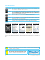
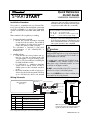
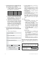
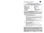
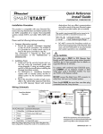
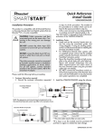
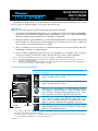
Quick Reference
User's Guide
DSM200/250, 3000/5000-series
Congratulations on the purchase of your state-of-the-art Directed SmartStart system. Reading this user’s guide
prior to using your system will get you off to a quick and smooth start.
Start Here
Before you can start using your system, the following steps must be performed:
1. Download the free SmartStart application to your smartphone from the iTunes App Store, BlackBerry
App World or Android Market site depending on which brand you own. Links to download BlackBerry
and Android apps are also available at www.directed.com/SmartStart
2. Have the SmartStart system installed by your authorized Directed dealer. Once installed and activated
by the installer, you will receive an e-mail prompting you to activate your account. Your installer can
also provide you with information about your system.
3. After you activate your account, enter your username and password on the More/Settings tab of the
handset app to activate your SmartStart app.
4. Once you have completed the log-in process on your smartphone, you can begin using your app to
control your vehicle(s). From the Car screen, select the vehicle you wish to send commands to.
Note 1:
Note 2:
Note 3:
Accessing SmartStart GPS features in the app requires installation of DSM250 SmartStart GPS module.
Accessing Home Control features in the app requires compatible home security panel. See www.alarm.com for more
details on compatible hardware.
Smartphone coverage for GPS and other features may differ by platform. Please visit www.directed.com/SmartStart for
the most current information on app/smartphone coverage.
Basic Commands at a Glance
System
Commands
Description
Select this icon to lock the vehicle. When a confirmation message is received, select it to clear.
Select this icon to unlock the vehicle. When a confirmation message is received, select it to clear.
Select this icon to remote start* your vehicle. When a confirmation message is received, select it to clear. The vehicle remote
starts and stays running for the programmed run time*. Select
this icon again to turn off the engine during the run time.
Select this icon to open trunk. A dialog box will open, asking
you to confirm you want to open the trunk. Select "Yes" to confirm, or "No" to cancel the request. If you selected "Yes", select
again to clear the confirmation message when it pops up.
System
Commands
*
Menu Bar
Select this icon to activate panic mode for 30 seconds. Select
again during this time to turn off. This feature is used to attract
attention if in a threatened position.
See your Remote Start system user's guide or installer for important information about starting a manual transmission vehicle and
how long the engine will run when remote started.
Your vehicle responds exactly the same, with audible and visual confirmations, for both Smartstart and remote control commands.
For more information on app features, use the in-app Help function.
QRGDSM250 2011-03
Menu Bar and Screens
Menu Bar
Description
Home
This screen is the default screen for direct access to all your remote commands. Select
any command on the Home screen to perform it.
Alerts
This screen provides alerts and notifications from the system. New alerts or notifications are indicated by a red circle above the Alerts icon which also indicates the number of uncleared notifications received. The available Alerts may vary depending on
the type of system installed in your vehicle.
Cars
This screen allows you to access and personalize your vehicle settings.
Track
This screen allows you to access SmartStart GPS features (requires SmartStart GPS
hardware and GPS Secure service plans).
More
Access settings and other advanced app features. Go to More/Settings to log in to
SmartStart, and use in-app Help function to explore additional feature details.
Screens
Home Screen
Alerts Screen
Cars Screen
Track Screen
More Screen
Please visit www.directed.com/SmartStart for the latest updates and information about your SmartStart system.
Note:
The amount of time it takes for your vehicle to respond to a command can be affected by cellular
coverage or network congestion.
Note:
Your SmartStart module automatically checks for updates once every 24 hours. During updates, system
operation is disrupted for approximately one minute.
2
© 2011 Directed Electronics. All rights reserved.
Quick Reference
Install Guide
VSM200/250, DSM200/250
obstructions that can affect communications
and within reach of the main Directed system
using the provided cables (do not extend).
Installation Procedure
This product is compatible with most Directed Electronics Security, Remote Start and hybrid systems that
are ESP2 compatible (3 or 4-pin). Non-compatible
systems include 3001L and older AM1/AM5 models.
The module's signal strength (RSSI) can be viewed in the
activation portal after a successful transmission test.
-50 to -90 dB
-91 to -100 dB
> -100 dB
Please read the following before proceeding
1. Customer Information required:
• Record the customer information requested
in step 4a of this procedure. The module ID
# is provided on a sticker which can be affixed to the space provided in step 4a.
This information is required for final verification/activation of the VSM200/250 or
DSM200/250.
2. Installation Points:
• Install and test the security/remote start system first using the associated guides and
wiring diagram. If using an existing system,
verify it is fully functional before installing the
Directed SmartStart module.
• For 3000-series or standalone SmartStart
systems with no remote control, test the installed system via the SmartStart activation
portal.
• Mount the SmartStart module as high as possible in the vehicle (the engraved side faces
up for GPS devices). Mount with minimal
= good signal strength
= borderline/inconsistent signal strength
= weak, insufficient signal strength
• DO NOT connect the SmartStart module until the final programming of the Remote Start
main unit and verification of security/remote
start system operations are completed.
CAUTIONS
The white plug is ONLY for RSR (Remote Start
Ready) and RXT applications using certain Xpresskit
interfaces (go to www.xpresskit.com for details on
supported devices & vehicles).
For systems with combined 4-pin ESP/D2D ports,
you CANNOT use an interface module in D2D
mode when using a SmartStart module. You must
use W2W on the bypass module.
DO NOT connect the black 3-pin ESP connector to
white Door Lock port on Directed systems.
There should NEVER be more than one data plug
connected from the 3-way harness.
Wiring Schematic
SmartStart Module
(Top view)
Configuration wires
Gray & White
5 pin (see table below)
Directed System
(Top view)
ESP (4 pin, brn)
or
ESP (3 pin, blk)
4 pin
LED
2 pin
Fuse
Not used here:
D2D (4 pin, wht)
Red: +12V
Black: Ground
5-pin Cable
Wire Color
Connection/Description
1
White/Blue
(-) RS (Remote Start)/AUX output
2
Brown
(-) Factory horn/Alert input
3
Green
(-) Lock
4
Blue
(-) Unlock
CPU1
Pin #
NOTE: The appearance and connector/port
arrangement on the Directed/Avital/Xpresskit
system may differ to the examples shown .
5
Red/White (-) Trunk/AUX output
Note: The analog output wires are only active if the device has
been configured for Analog Wire mode in the installation portal.
SmartStart Module to Xpresskit
✂
cut loop (see table)
QRNDSM250 2011-10
3. Install the VSM200/250 or DSM200/250 using
the information in the wiring diagram and steps
(Note CAUTIONS during installation).
a. Configuration Wires: Connect the loose gray
or white configuration wire(s) to match the
desired application (see table below).
MODE
GRAY WIRE
WHITE WIRE
ESP2
Open
Open
D2D, RSR/RXT
GND
Open
Autostart/AstroStart
Open
GND
b. Connect the serial data cable and adapter to
the correct port of the main module. For D2D
RSR/RXT applications, connect the serial
data cable and adapter to Xpresskit module.
c. Complete the main power connections.
d. When power is connected, the module begins an initialization procedure that may
take several minutes. During this procedure,
progress is reported via the flashing Amber/
Green LEDs next to the module cable. When
both LEDs turn on solid, the initialization procedure is completed (See Status LEDs for a
description of the various LED states).
4. Verify and Activate the SmartStart module:
The following steps need to be performed for the
Verification/Activation of the Directed SmartStart
module.
a. Collect Customer Information:
Customer's Full Name:
Customer's E-mail Address:
Customer's mobile phone # and phone carrier
Record/place Module ID # here:
b. Log on to: www.directechs.com, and click on
the SmartStart link.
c. Follow the on-screen directions to activate
and test a SmartStart device. If this is the customer's first SmartStart system, you will be
prompted to enter their information as collected in step 4a.
d. Set configuration for commands to match the
installed application.
e. Test the SmartStart system from the website
using the supplied function links.
f. The customer is sent log-in information via
e-mail. After logging into the site at www.
mysmartstart.com, they must select and pay
for the service plan in order to start using the
system.
Status LEDs
Amber LED states:
• Off: No cellular communication. Check
connections such as module harness.
• Flashing slowly: The module is seeking
cellular system communication.
If no cell coverage is available the Amber
LED continues to flash slowly, move the
vehicle to a location with better reception.
• Flashing quickly: The module is negotiating with a cellular system.
• On solid: Communication successfully established.
Green LED states:
• Off: Communication not established with
the remote start main unit or no serial device is connected.
Check connection at the Bitwriter port,
once connected properly the LED turns on
after resetting the power to the SmartStart
module.
• On solid: Communication successfully established with the remote start main unit.
Please return this guide and point the customer to
steps 4a and 4f after successfully completing the installation as it contains details required for account
setup.
Directed Logo Usage
New Account:
Existing Account:
If this is an existing account, are you:
adding a new system:
or replacing an existing one:
Notes: SmartStart response time can vary depending on cellular coverage and network congestion.
Operating temperature range: -30°C to + 70°C.
Logo, Directed with designed in USA.eps
Additional information
can be found at:
www.directechs.com
Logo, Directed Electronics w-driven.eps
2
© 2011 Directed Electronics. All rights reserved.
Logo, Directed with Distributed By.eps
/i:\ Warning! Safety first~---------~---~---~-~-----~~---~---~----The following safety warnings must be observed at all times:
Due to the complexity of this system, installation of this product must only be performed by an authorized
Directed dealer.
When properly installed, this system can start the vehicle via a command signal from the remote control transmitter. Therefore, never operate the system in an enclosed area or partially enclosed area without ventilation
(such as a garage). When parking in an enclosed or partially enclosed area or when having the vehicle
serviced, the remote start system must be disabled using the installed toggle switch. It is the user's sole responsibility to properly handle and keep out of reach from children all remote control transmitters to assure that the
system does not unintentionally remote start the vehicle. WE RECOMMEND THE USER INSTALL A CARBON
MONOXIDE DETECTOR IN OR ABOUT THE LIVING AREA ADJACENT TO THE VEHICLE. ALL DOORS LEADING FROM ADJACENT LIVING AREAS TO THE ENCLOSED OR PARTIALLY ENCLOSED VEHICLE STORAGE
AREA MUST AT ALL TIMES REMAIN CLOSED. These precautions are the sole responsibility of the user.
Remote starters on manual transmission vehicles operate differently than those with automatic transmission
because you must leave your car in neutral. You must read this Owner's Guide to familiarize yourself with
the proper procedures regarding manual transmission remote starters. If you have any questions, ask your
installer or contact Directed at 1-800-753-0600.
Before remote starting a manual transmission vehicle, please note and follow these instructions:
•
Leave the vehicle in neutral and be sure no one is standing in front or behind the vehicle.
• WARNING! Only remote start on a flat surface
•
Have the parking brake fully engaged
WARNING! It is the responsibility of the owner to ensure the parking/emergency brake properly functions.
Failure to do so can result in personal injury or property damage. We recommend the owner have the parking/emergency brake system inspected and adjusted by a qualified automotive shop biannually.
Use of this product in a manner contrary to its intended mode of operation may result in property damage,
personal injury, or death. (1) Never remotely start the vehicle with the vehicle in gear, and (2) Never remotely
start the vehicle with the keys in the ignition. The user must also have the neutral safety feature of the vehicle
periodically checked, wherein the vehicle must not remotely start while the car is in gear. This testing should
be performed by an authorized Directed dealer in accordance with the Safety Check outlined in the product
installation guide. If the vehicle starts in gear, cease remote start operation immediately and consult with the
authorized Directed dealer to fix the problem.
After the remote start module has been installed, contact your authorized dealer to have him or her test the
remote start module by performing the Safety Check outlined in the product installation guide. If the vehicle
starts when performing the Neutral Safety Shutdown Circuit test, the remote start unit has not been properly
installed. The remote start module must be removed or the installer must properly reinstall the remote start
system so that the vehicle does not start in gear. All installations must be performed by an authorized Directed
dealer.
OPERATION OF THE REMOTE START MODULE IF THE VEHICLE STARTS IN GEAR IS CONTRARY TO ITS INTENDED MODE OF OPERATION. OPERATING THE REMOTE START SYSTEM UNDER THESE CONDITIONS
MAY RESULT IN PROPERTY DAMAGE OR PERSONAL INJURY. YOU MUST IMMEDIATELY CEASE THE USE
OF THE UNIT AND SEEK THE ASSISTANCE OF AN AUTHORIZED DIRECTED DEALER TO REPAIR OR DISCONNECT THE INSTALLED REMOTE START MODULE. DIRECTED WILL NOT BE HELD RESPONSIBLE OR PAY
FOR INSTALLATION OR REINSTALLATION COSTS.
This product is designed for fuel injected vehicles only. Use of this product in a standard transmission vehicle
must be in strict accordance with this guide.
This product should not be installed in any convertible vehicles, soft, or hard top with a manual transmission.
Installation in such vehicles may pose certain risk.
2
© 2009 Directed Electronics. All rights reserved.
UMITED ONE YEAR CONSUMEBJIJIARRANTY:_ ________
_
For a period of ONE YEAR from the date of purchase of a Directed Electronics SmartStart remote start
product, Directed Electronics ["DIRECTED"] promises to the original purchaser, to repair or replace with
a comparable reconditioned piece, the SmartStart remote start module [here inafter the "Part"]. which
proves to be defective in workmanship or material under normal use, provided the following conditions
are met: the Part was purchased from an authorized DIRECTED dealer; and the Part is returned to DIRECTED, postage prepaid, along with a clear, legible copy of the receipt or bill of sale bearing the following information: consumer's name, address, telephone number, the authorized licensed dealer's name
and complete product and Part description.
This warranty is nontransferable and is automatically void if the Part has been modified or used in a manner contrary to its intended purpose or the Part h_as been damaged by accident, unreasonable use, neglect, improper service, installation or other causes not arising out of defect in materials or construction .
TO THE MAXIMUM EXTENT ALLOWED BY LAW, EXCEPT AS STATED ABOVE, ALL WARRANTIES, INCLUDING BUT NOT LIMITED TO EXPRESS WARRANTY, IMPLIED WARRANTY, WARRANTY OF MERCHANTABILITY, FITNESS FOR PARTICULAR PURPOSE AND WARRANTY OF NONINFRINGEMENT OF INTELLECTUAL
PROPERTY, ARE EXPRESSLY EXCLUDED; AND DIRECTED NEITHER ASSUMES NOR AUTHORIZES ANY
PERSON OR ENTITY TO ASSUME FOR IT ANY DUTY, OBLIGATION OR LIABILITY IN CONNECTION WITH
ITS PRODUCTS. DIRECTED HEREBY DISCLAIMS AND HAS ABSOLUTELY NO LIABILITY FOR ANY AND ALL
ACTS OF THIRD PARTIES INCLUDING DEALERS OR INSTALLERS. IN THE EVENT OF A CLAIM OR A DISPUTE INVOLVING DIRECTED OR ITS SUBSIDIARY, THE PROPER VENUE SHALL BE SAN DIEGO COUNTY IN
THE STATE OF CALIFORNIA. CALIFORNIA STATE LAWS AND APPLICABLE FEDERAL LAWS SHALL APPLY
AND GOVERN THE DISPUTE . THE MAXIMUM RECOVERY UNDER ANY CLAIM AGAINST DIRECTED SHALL
BE STRICTLY LIMITED TO THE AUTHORIZED DIRECTED DEALER'S PURCHASE PRICE OF THE PART. DIRECTED SHALL NOT BE RESPONSIBLE FOR ANY DAMAGES WHATSOEVER. INCLUDING BUT NOT LIMITED TO , ANY CONSEQUENTIAL DAMAGES, INCIDENTAL DAMAGES, DAMAGES FOR THE LOSS OF TIME,
LOSS OF EARNINGS, COMMERCIAL LOSS, LOSS OF ECONOMIC OPPORTUNITY AND THE LIKE. NOTWITHSTANDING THE ABOVE, THE MANUFACTURER DOES OFFER A LIMITED WARRANTY TO REPLACE OR
REPAIR AT DIRECTED 'S OPTION THE PART AS DESCRIBED ABOVE.
Some states do not allow limitations on how long an implied warranty will last or the exclusion or limitat ion of incidental or consequential damages. This warranty gives you specific legal rights and you may
also have other rights that vary from State to State . DIRECTED does not and has not authorized any person or entity to create for it any other obligation, promise , duty or obligation in connection with this Part.
VSM 100 2009-09warranty