1
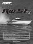
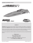
™
™
2008 and 2009 World Champion!
WARNING:
• NEVER attempt to swim after a stalled RC boat!
• Never operate your RC boat while standing in the water.
• Never operate your RC boat in the presence of swimmers.
• Always use a Personal Flotation Device (PFD) when boarding and operating your retrieval craft, i.e. Jon boat or duck boat.
NOTE: Because of the sharp running hardware included with this RC boat, we do not recommend a rubber blow up raft.
• RC boat running hardware is very sharp. Be very careful when working on and around the metal parts.
• While the engine is running pay close attention to the propeller. Do not come in contact with the propeller at any time the
engine is running or serious injury will result.
• AquaCraft products are to be used by ages 14 and over.
aquacraftmodels.com
INTRODUCTION & DESCRIPTION CHANGES
Thank you for purchasing the AquaCraft Top Speed 3 (TS3). We at
AquaCraft want the time you spend with your boat to be safe, fun
and successful. If for any reason you feel this R/C model is not for
you return it to your place of purchase immediately. Your hobby
dealer cannot accept returns on any model after final assembly or
after your boat has been operated.
AquaCraft products are to be used by ages 14 and over.
All pictures, descriptions, and specifications found in this instruction
manual are subject to change without notice. AquaCraft maintains
no responsibility for inadvertent errors in this manual.
ITEMS INCLUDED
➧ Pre-Painted Top Speed 3 Hull and Cowl
➧ Radio Box, Fuel Tank and Fuel Tank Mount
➧ Running Hardware
➧ Decals
PARTS NEEDED TO COMPLETE YOUR MODEL
AND OPTION PARTS
RADIO SYSTEM: Most any radio equipment will work quite well in
your new boat, but to aid in selection we have provided you with
three possible options.
OPTION 1: (This option is the least expensive of the three but still
has plenty of range and power for tunnel boat racing.)
❏ 1-TACJ0245 Tactic™ 2.4 Radio system less servos
❏ 1-FUTM0031 Futaba® 3003 Standard Servo (Throttle)
❏ 1-FUTM0045 Futaba 3305 High-Torque Standard Servo with
Metal Gears (Steering)
❏ 2-FUGP7300 Fuji AA batteries (4 pack)
OPTION 2: (This option has a transmitter that has multiple model
memory, allowing you to easily grow as your racing program
grows.)
❏ 1-FUTK2021 Futaba 3PM-X Radio system less servos
❏ 1-FUTM0031 Futaba 3003 Standard Servo (Throttle)
❏ 1-FUTM0102 Futaba S9402 High-Speed Coreless BB
(Steering)
❏ 3-FUGP7300 Fuji AA batteries (4 pack)
OPTION 3: (This option costs the most money and is top of the
line equipment.)
❏ 1-FUTK4900 Futaba 4PK Radio system less servos
❏ 1-FUTM0031 Futaba 3003 Standard Servo (Throttle)
❏ 1-FUTM0236 S9315 Digital High Torque Servo (Steering)
❏ 1-FUTM1383 Futaba NRT5 5Cell NiCd RX battery
2
ENGINE:
❏ O.S.® 21XM Marine Outboard Engine (OSMG1721)
ACCESSORIES NEEDED TO OPERATE YOUR MODEL:
❏ AquaCraft Fuel Line (AQUB6903)
❏ TorqMaster™ Electric Starter (HCAP3200)
❏ 30% Boat Fuel, Quart (AQUP2230)
or
❏ 50% Boat Fuel, Quart (AQUP2250)
❏ Hot Shot 2™ Glow Igniter (HCAP2520)
❏ Hand Crank Fuel Pump (HCAP3015)
❏ Fuel Line (AQUB6903)
❏ Fuel Filter (GPMQ4150)
❏ Glow Plug Wrench (GPMP2000)
❏ AquaCraft GrimRacer™ Pro Radio Box Tape (AQUB9514)
❏ AquaCraft GrimRacer Speed Grease (AQUB9500)
EXTRAS:
#ODOG0309 ❏ O’Donnell™ OD-9 Glow Plug (ODOG0309)
or
#OSMG2690 ❏ O.S. #6 A3 Glow Plug Hot (OSMG2690)
TOOLS NEEDED TO COMPLETE YOUR MODEL:
❏ Boat Stand (see how to make a Boat Stand on page 4)
❏ Setup board (see how to make a setup board on page 4)
❏ Medium CA glue or 12 minute epoxy
❏ #1 “Small” Phillips screwdriver
❏ 1.5mm hex wrench
❏ 2.5mm hex wrench
❏ 4mm nut driver
❏ Pliers
❏ Hand drill
❏ Drill bits, 1/16", 5/64", 1/8" and 9/64"
❏ Silicone sealer
❏ Household cement (like Goop)
❏ Masking tape
❏ Moto Tool with cut off wheel
❏ 6" machinist ruler
❏ Hobby Knife
❏ Scissors
❏ Thread locking compound
WARRANTY SERVICE
SAFETY PRECAUTIONS
AquaCraft will warrant your model for 90 days after the purchase
from defects in materials or workmanship of original manufacture.
AquaCraft, at their option, will repair or replace at no charge, the
incorrectly made part. This warranty does not cover damage caused
by crash, abuse, misuse, alteration or accident. To return your boat
for service you need to provide proof of purchase, your store receipt
or product invoice will suffice.
• Never, ever, attempt to swim after a stalled RC boat. DO NOT
get in the water for any reason to retrieve your boat. Your TS3
has flotation added to the interior of the hull and the cowl. They
will not sink. To aid you in retrieving a stalled RC boat you can
use a fishing reel with a tennis ball tied to the end of the line. Or
better yet, get yourself a small Jon boat so you can row out and
pick up your boat. Remember to use a PFD any time you enter
your retrieval craft.
IN NO EVENT SHALL THE PURCHASER BE ENTITLED TO ANY
INCIDENTAL, SPECIAL, INDIRECT OR CONSEQUENTIAL DAMAGES,
WHETHER RESULTING FROM THE USE, MISUSE OR INABILITY TO
USE THE PRODUCT OR FROM DEFECTS IN THE PRODUCT.
This warranty gives you specific legal rights and you may also have
other rights, which vary from state to state.
Outside USA and Canada, contact local importer for warranty
information.
Hobby Services
3002 N. Apollo Drive, Suite 1
Champaign, Illinois 61822
Attn: Service Department
Phone: (217) 398-0007 9:00 am - 5:00 pm Central Time M-F
E-mail: [email protected]
FEATURES & SPECIFICATIONS
BOAT SPECIFICATIONS:
Hull Length: 30" (765mm)
Overall Length: 36" (915mm)
Width: 10.5" (265mm)
Height: 6" (154mm)
Weight (less fuel): 5 lbs (2.3 kg)
• AquaCraft products are to be used by ages 14 and over.
• Do not touch the propeller anytime the engine is running. Pay
equally close attention to items such as loose clothing, shirtsleeves,
ties, scarves, long hair or anything that may become entangled in
the spinning prop. If your fingers, hands, etc. come in contact with
the spinning propeller, you may be severely injured.
• The speed and mass of this boat can inflict property damage and
severe personal injury if a collision occurs. Never run this boat
in the presence of swimmers or where the possibility of collision
with people or property exists.
• Glow engines produce heat. Do not touch any part of your engine
until it has cooled.
• This boat is controlled by radio signals, which are susceptible to
possible interference from other R/C transmitters, paging systems,
or other electrical noise. Before turning your radio transmitter and
receiver on, make sure no one else in the area is operating a radio
on the same frequency (channel).
• If your TS3 should happen to stall, water currents will slowly carry
it to shore. The bad news is that the boat could be carried to the
opposite shore. When surveying areas to run your model, keep
variables in mind such as wind direction, size of the lake, etc. It is
not advisable to run R/C boats on any free-flowing bodies of water
such as creeks or rivers.
BOAT FEATURES:
Race-winning heritage
Fiberglass construction
High gloss, fuel-resistant painted finish
Water-resistant radio box
8 oz molded plastic fuel tank
3
BOAT STAND
You are going to want to build the boat stand as soon as you can. It makes assembling the boat easier and the stand can be used as the
starting stand for the boat as well.
There are a lot of ways to build a boat stand, but we would like to show you one way that is inexpensive and durable.
PARTS YOU WILL NEED:
❏ (8) 1" PVC T’s
❏ (2) Lengths of 1" PVC piping 16" long
❏ 2 – Lengths of 1" PVC piping 11-1/2" long
❏ 4 – Lengths of 1" PVC piping 2" long
❏ 2 – Lengths of 1" pipe insulation 11-1/2" long
❏ PVC cement (like the tube kind for boat stand building)
Pre-assemble the parts without using any cement first. Then
disassemble and reassemble using the cement.
Assembly is easy, as the long 16" lengths of PVC piping run the
length of the boat and the shorter 11-1/2" lengths side-to-side.
Glue the Ts to the ends of the tubing, making sure the Ts are
parallel to each other. Join the completed parts together using the
short 2" lengths of piping. You will have to work fast as the cement
sets the parts almost instantly.
SETUP BOARD
Your setup board is going to be a very important tool in getting your boat to perform at its best. Here is a simple how to:
Using MDF or common shelf board (do not use plywood or a media with a grain), cut the board 25" long and 11" wide. Place a slot 1/2"
wide on one end of the board, aligning it in the center of the 11" width.
The nice thing about this setup board is it fits between the Ts of
the boat stand you just made, making boat setup even easier by
keeping the skeg of the engine a safe distance from the table top.
GrimRacer says: It’s a good idea to
place a hole in one end of the setup
board and hang it from a hook or nail for
storage. This will help keep the setup board true.
4
PREPARING THE ENGINE
FOR THIS STEP YOU ARE GOING TO NEED:
➧ #1 Phillips screwdriver
➧ 4mm nut driver
➧ Thread locking compound
Prepare the engine by installing the metal ball links to the
engine tiller arm. You are going to want to install the ball
links in the inner most holes of the tiller arm. You might have
to enlarge the holes of the aluminum tiller arm to allow the
screw to pass through. It’s a good idea to use a little thread
locker on the screw to help secure the parts. Now is also a
good time to check the direction of the mount plate to make
sure it’s positioned with the pivot boss near the bottom.
You can also install the throttle cable clamp at this time.
FOR THIS STEP YOU ARE GOING TO NEED:
➧ Scissors or hobby knife
➧ Hand drill with both 1/8" and 9/64" drill bits
➧ 2.5mm hex wrench
➧ Masking tape
Cut engine mounting template from the back of this manual.
Center the template on the transom and tape in place. Use a 1/8"
drill bit and drill the center marks on the template. Remove the
template and enlarge the holes by re-drilling with a 9/64" drill bit.
5
Slip the metal backing plate into the opening in the back of the
boat. You will have to rotate it 90° to align the screw holes.
Attach the engine to the boat using the 3mm bolts
and washers supplied in the kit. Don’t worry about
setting the engine height at this time as we will get
to that during the “setup” part of the manual.
FOR THIS STEP YOU ARE GOING TO NEED:
➧ Medium CA glue or 12 minute epoxy
➧ Hand drill with 1/16” drill bit
➧#1 Phillips screwdriver
Glue the fuel tank tray together. Waterproof
the tray by applying a coat of epoxy.
6
Center the tray on the back tank platform. Using a
1/16” drill bit, pre-drill the mounting holes.
Screw the tray in place using the provided 2mm wood screws.
Install the fuel tank to the mount using the supplied O rings.
7
RADIO BOX ASSEMBLY
FOR THIS STEP YOU ARE GOING TO NEED:
➧ Medium CA glue or 12 minute Epoxy
➧ #1 Phillips screwdriver
➧ 1.5mm hex wrench
➧ Moto tool with cut off wheel
➧ Hobby knife
➧ Household cement or silicone sealer ➧ Pliers
➧ Hand drill with 1/16" and 5/64" drill bits
With the switch mounting feature towards the starboard
side (right side of the box when viewed from behind), glue
the servo tray onto the standoffs inside the radio box.
Install the two waterproof boot mounting plastics
by sliding them in from the inside of the box.
Use medium CA to glue them in place.
8
Use a 5/64" drill bit to enlarge the hole in the
switch for the ON/OFF switch pushrod.
Slip the switch (ON facing to the front of the
boat) through the throttle servo opening.
Place the switch plate in place.
Slide the ON/OFF pushrod in the box, positioning the
hook in the end of the wire through the switch. It is
best to install the wire through the hole in the switch
from the box side so it cannot fall out during use.
9
Screw the switch in place; do not overtighten the screws.
Install and glue in the small rubber rod seal by slipping
it over the ON/OFF wire and gluing it in place.
Install the servos next. The front opening is for the throttle
servo and the rear for the steering servo. Install the servos
so the output shafts are towards the front of the radio box.
GrimRacer Says: The metal eyelets that
come with the servos are inserted from
the bottom side of the servo; this way the
rubber grommet is captured by the flange of the eyelet and
the built-in washer of the servo screw. This provides the best
vibration protection and strongest mounting for the servo.
Remove the servo arms from the servo and
clip the spokes as shown in the picture.
10
On the dual servo arm only, use a 5/64" drill bit to
enlarge the holes furthest out on the servo arm spokes.
Do not enlarge the hole on the single servo arm.
Here are the parts we need for the next step.
Slip the 90° end of the short steering pushrod
into the servo arm from the bottom.
Add the pushrod keeper and snap it into place. Repeat
with the other side to complete the assembly
11
Slide the completed steering servo arm
into the radio box from the inside.
The rods protrude through the pushrod rubber seal mounts.
Slip the rubber seals over the rods. Be careful not
to puncture the seals, and glue them in place.
This is what the radio box looks like thus far.
12
Install the screw lock connector onto the servo arm
with the one remaining spoke. Slip it onto the servo
for safe keeping. At this time it’s a good idea to loosely
install the servo arm screws so as not to lose them.
Next we are going to install the throttle cable. Begin by
cutting the white outer housing to 17-1/4" (438mm)
long. Next take the remaining small rod seal and
remove half of the pointed end with a sharp knife.
Slip the outer housing through the seal, positioning it about
2-1/2" (64mm) from the opposite end of the housing.
Glue the seal in the radio box, being careful not to get
any glue on the white outer housing. We are going
to adjust the position and glue the housing to the
seal later in the setup portion of the manual.
13
Although not necessary, we recommend tack gluing
the radio box into the boat with a few small dabs
of household cement or silicone sealer.
Install the steering rods onto the engine by
snapping the ball link over the metal ball.
Slip the lock collars over the long rods and then back
over the short rods protruding from the radio box. Snug
the lock collars in place. We will make final adjustments
to the steering rods in the setup part of the manual.
Slip the white outer housing in the clamping portion of the
cable clamp and snug the other housing in place. If you
find the cable is not held well, you can carefully sand some
of the thickness of the upper portion of the clamp to allow
better clamping. (Do not overtighten the clamp screw).
14
Using a moto-tool and cut off wheel, cut the stainless
throttle cable 20-3/4" (527mm) long. It’s best to place a
short length of masking tape over the cable and place the
mark on the tape. Cut the mark with the tape in place.
Slip the short length of fuel tubing over the
cable and up to the metal clevis.
Next slide the cable into the white outer housing; as you
do this, get ready to guide the cable through the screw
lock connector (do not tighten the connector).
Attach the metal clevis to the throttle arm of the engine
and slip the silicone tubing over the metal clevis.
15
Next we are going to install the ON/OFF pushrod guide.
Slip the guide over the pushrod and
position it as shown in the picture.
Using a 1/16" drill pre-drill a pilot hole for the
2mm wood screw. Screw the guide in place.
Next, using a set of pliers, put a 90° bend in the end of the rod.
16
If your receiver has an external antenna you can use
the include antenna to extend it from the radio box.
Drill a 1/4" hole approximately 1" from one end of the
radio box lid and install the antenna using a dab of
silicone between the hole and the base mount.
GrimRacer Says: If you are using a
2.4GHz radio system you can shorten
the antenna tube to 5" long. Do not drill
a hole in the top of the cowl but rather allow the antenna
to gently bend under the cowl for a neat and clean look.
Glue the plastic washers on the cowl. Use a
small amount of CA to hold them in place.
17
FINAL CHECKS AND SETUP
Position the lower unit into the slot on the set up board.
Using a small machinist rule (you can get one at your local
home store), adjust the engine so the distance between
the boat stand and the bottom of the cavitation plate are
30mm at the front and 28mm at the back. This will get you
close in both the height and tilt for your first test runs.
Having completed this, remove one engine mount bolt
at a time and place some silicone sealer on the bolt and
re-install it. Do this with all 4 engine mount bolts.
Place the provided foam into the bottom of the radio
box and insert the receiver battery pack. Place the
receiver in the box as well. Do your best to place the
receiver so as not to stress the servo plugs.
18
Detach the servo arms from the top of the servos and
turn the radio system on. Adjust the steering arm to
center and the throttle arm to the position shown in the
photo and re-install the arms and servo arm screws.
Check the direction of both the steering and throttle
movement. NOTE: The throttle arm will move forward (front
of boat) to open the carburetor. Adjust the lock collar on the
steering arms so the engine is centered with the steering
wheel in the center position. Tighten the lock collars.
With the metal clevis attached to the throttle arm,
make sure you are getting a full range of motion.
GrimRacer Says: Adjusting the throttle
can be a tad more difficult so please
follow along closely. IMPORTANT:
After you have the throttle movement adjusted, you are
going to want to glue the white outer cable housing to
the rubber seal as it exits the radio box. The two must
be secure to maintain the throttle adjustment.
Make sure the carburetor barrel can fully open as
well as fully close.NOTE: If you are not getting a full
range of motion you might need to loosen the set
screw (1.5mm hex wrench) on the carburetor arm and
reposition the arm on the barrel of the carburetor.
19
Squeeze the throttle trigger on the transmitter as well
as push the throttle barrel into the full throttle position.
Snug the set screw on the screw lock connector.
Carburetor Closed
Release the throttle trigger and the carburetor
barrel should go to high idle.
Carburetor Partially Open (Idle)
Push the throttle trigger forward and the carburetor
barrel should FULLY close. Make any necessary small
adjustments to make sure that the barrel FULLY closes.
Carburetor Fully Open
Hook up your fuel and pressure line using the picture
for reference. The use of a fuel filter is not required
but is recommended for the first few runs.
20
STARTING AND OPERATION
CARE AND MAINTENANCE
Check and adjust the high-speed needle on your engine for a safe
break in setting (2 turns out for the OS XM Outboard Engine) The
prop that is supplied with the OS engine will operate the boat just fine
but most boaters use metal props as they provide better handling as
well as speed and power.
1. Using a hand or electric fuel pump (hand crank is recommended)
fill the fuel tank through the line that attaches to the carburetor.
2. Turn the transmitter on and then the receiver, in that order.
3. Attach the hand held electric starter to a 12V battery and choke
the engine by placing your thumb over the barrel of the carburetor.
Turn (Crank) the engine over with the starter 3 or 4 times in short 2
second bursts.
4. Install the glow igniter and crank the engine. It should start in less
than 10 seconds. If it takes longer than that, re-prime the engine
by removing the igniter and re-choking the engine. Repeat this if
needed until you have the engine running.
GrimRacer Says: It is VERY important to NEVER run the engine
with the carburetor fully open with no load
on the propeller. The engine can, however,
sustain high idle for a minute or two and not
be damaged. Bottom line, you are going to want to launch the boat
into the water as soon as practical.
5. After the engine is running, launch the boat, applying a little more
throttle before the boat touches the water. Drive the boat straight
way from you at around half throttle to check the steering center. If
needed, adjust the steering trim on your transmitter for straight and
true tracking.
➧ Your Top Speed 3 can turn either left or right quite well but due
to prop torque the boat turns best to the right (Clockwise). You can
start breaking the engine in by making large, right-hand, oval shaped
circuits. Throttle up and down during the run to keep the engine
running and to load the engine throughout the throttle range. Before
the boat runs out of fuel (about 4 minutes), bring in the boat and allow
the engine to fully cool. Repeat the same break-in run one more time
before we start to lean down the engine for the final break-in runs.
➧ When you’re ready to bring the boat in, drive it parallel to shore and
push back on the trigger to stop the engine. Never bring your boat
to shore by driving it straight at you. Always drive parallel to shore,
stop the engine and then retrieve the boat. This way if your engine
does not stop you can still go around and make another attempt.
➧ Finish breaking in the engine per the engine manufacturer’s
recommendations.
➧ If you should happen to flip your TS3, you are going to need
to remove any water that might have entered the engine. We
recommend removing the glow plug and turning the engine over a
few times by hand to remove water. After most of the water has been
removed, leave the glow plug out and turn the engine over with the
electric starter expelling the rest of the water.. Make sure you hold a
rag over the glow plug hole. NOTE: Be careful to keep your rag and
fingers away from the spinning prop. Re-install the glow plug and
start the engine. It is best to start the engine after you have flipped
the boat to make sure ALL THE WATER IS OUT OF THE ENGINE. It
is also a good idea to inspect the radio box to make sure no water
entered the radio compartment.
If you should happen to drip or spill fuel on the finish of your TS3,
carefully wipe it off as soon as you can. Some fuels, especially high
nitro fuels and special oil additives can damage your boats finish.
After you’re done boating for the day, you are going to want to add
some after-run oil to the engine to protect the internal parts. We
recommend removing the glow plug, opening the carburetor all the
way, and placing 10 to 12 drops of after-run oil down the barrel of
the carburetor. Place a rag over the glow plug hole and turn the
engine over with the electric starter. Repeat this step a least one
more time to make sure the inside of the engine is fully coated.
Replace the plug and wipe the boat down with cleaner.
It is also a good idea to open the radio box and unplug the battery
from the switch harness. Leave the lid off the radio box overnight to
make sure any water that might have entered can evaporate.
Clean the exterior of the boat and check over the mounting hardware.
HULL TUNING TIPS
PERFORMANCE PROPS WORTH NOTING:
AquaCraft GrimRacer
40x52/3 Metal Prop
AQUB9720
AquaCraft GrimRacer
40x53 Metal Prop
AQUB9715
MAJOR TUNING AREAS OF YOUR TS3:
➧ Propeller Shaft (Stub Shaft) Height
➧ Propeller Shaft (Stub Shaft) Angle
➧ Hinge Pin Angle
➧ Center of Gravity (CG)
➧ Propeller
➧ Rudder Deflection
Propeller Shaft (Stub Shaft) Height: To simplify, what we are trying
to do with propeller shaft height is to “raise the propeller to a height
that gives us the greatest speed with the least loss in stability”. Let’s
expand on this.
To measure the height of the shaft most racers use a setup board. A
typical tunnel hull setup board can be a simple piece of shelf board
with a slot cut into on end so the user can reference the height of the
prop to the bottom riding surface of the sponsons.
Adjusting the shaft height plays a huge part in the speed as well as
the handling of the boat. Typically, adjusting the propeller higher
21
makes the boat run faster but at a greater risk of blowing the boat
off the water (flipping it over backwards). It also can cause loss of
steering in the corners if set too high. Lowering the shaft has the
opposite effect and makes the boat more stable but can slow the
boat considerably. It is also important to note that having the shaft
too low can cause the boat to stuff or tuck under going around the
corner. Setting the shaft (prop height) is a very important part of
tuning your boat. It is also good to note that even 1/16" higher or
lower can make or break a good running tunnel boat.
Propeller Shaft Angle: Changing the propeller shaft angle causes
the bow of the boat to either run higher or lower depending on the
angle. What we are trying to accomplish by changing the shaft angle
is to loosen up the boat on the water to make it go as fast as possible
More positive (+) shaft angle lifts the bow, causing the boat’s tunnel
to capture more air, hence less drag and more speed. The risk of
having too much positive shaft angle is the possibility of blowing the
boat off the water. Too much negative (–) and the boat will run too
wet. Typical modern RC tunnel boats run with about 1/2° of negative
(–) shaft angle.
Hinge Pin Angle: (shimming required) Not all outboard engine
mounting systems allow you to change the hinge pin angle
separately from the stub shaft angle. It is worth noting, however,
that outboard engines that do have a distinct advantage over the
ones that don’t. Let me explain. When the servo swings your engine
left or right, the stub shaft follows the arc that the hinge pin has set
for it. If you have a positive hinge pin angle your stub shaft swings in
a positive, neutral, positive motion ( + 0 + ). If your hinge pin angle is
set negative, your stub shaft swings in a negative, neutral, negative
motion ( – 0 – ). It’s important to note this as the more positive angle
the hinge is set at, the higher the bow raises in the corners and the
opposite regarding negative pin angle. These can be a huge tuning
advantage for the way you drive. To adjust the hinge pin angle you
must shim either the top or the bottom of the engine mount plate
from the transom.
boat can become an instant winner just by using the right propeller.
As a rule of thumb, non-lifting propellers are best-suited for your
tunnel hull. Some lifting propellers can work but typically need to
be “re-worked” to work well on a Tunnel Hull. For the best overall
performance stick with a low lift propeller like the AquaCraft
GrimRacer 40X53 or AquaCraft GrimRacer 40X52/3. Testing your
propeller is best done with a stopwatch. The most important reading
is the time the boat takes to go from buoy one (1) to buoy three (3)
IMPBA and buoys one (1) through five (5) NAMBA. Second most
important time to capture is over all lap speed. Your boat may sound
or look faster with a prop change, but don’t let that fool you. Course
timing is the best way to determine what if any changes your prop
change as made.
Rudder Deflection: Your TS3 needs very little rudder deflection to
make it around a corner. Obviously your boat will turn tighter with
more rudder deflection but the truth is this can upset the boat in the
corners. It is best to have just enough rudder deflection to make a
nice sweeping corner PLUS just a tad tighter. To set the amount of
rudder deflection, run your boat on the race course and half throttle.
Adjust the steering dual rate until the boat makes a nice sweeping
corner a few feet off the buoys. Next: Run the boat at top speed
(remember to lift off the throttle just a little going into the corner)
and drive the course. Add in more dual rate until the boat runs the
course smooth and fast. Give a few more clicks on the dual rate
adjustment. The extra movement might be needed to get you out of
danger in the middle of a race.
TOP SPEED 3 BASIC SETUP PARAMETERS
You are going to want to avoid engine mounts that set the hinge
pin past the back of the sponsons. Having the pin in front of the
sponson we call under steer, and behind the back of the sponsons
over steer. The TS3 likes the pin in the under steer position.
Center Of Gravity (CG): The center of gravity “balance” of your
boat is just as important as other adjustments you make. Adding
or removing weight from the front of the boat ultimately decides the
stability of the boat as it flies over the top of the water. The further
forward you have the CG, the more speed the hull can handle, but like
other adjustments to your boat comes with a price. As a model tunnel
boat operates the boat’s ride can become disrupted. Any “acting
forces” i.e. wind, waves, drag and or acceleration/deceleration can
cause the boat to lose its balance. A properly set CG gives you the
best overall balance regarding all those changing conditions.
Propeller: First and foremost you need to balance or use a balanced
propeller. Not only will this provide the best performance but it is
necessary to avoid damaging your engine. You can learn more about
how to balance your propeller at www.aquacraftmodels.com
The propeller is probably the most important aspect of how fast
your boat goes and/or how well it handles. A poor handing, slow
22
ENGINE
HEIGHT
PROPELLER
THRUST ANGLE
HINGE PIN
ANGLE
C.G.
RANGE
PROP
RUDDER
DEFLECTION
.200" Center of the prop shaft
to the bottom of the sponsons
.5° Negative
Parallel to the transom
7.5" (27%) to 8.6" (31%)
from the back of the sponsons
AQUB9720 – 40X52/3
1-3/4" left
1-3/4" right
DRIVING AND RACING TIPS FROM 12-TIME
NATIONAL & WORLD RACING CHAMPION
MIKE “GRIMRACER” ZABOROWSKI
GrimRacer Says: Don’t just drive your TS3
around, drive your TS3 around something! To
reach the full potential this boat has to offer,
you need to get it on the water running around the race course.
Running your boat on the race course allows you to build depth
perception as well as get to know the needs of the boat.
➧ The TS3 responds best if you drive it as if you were driving a car
or any other type of wheeled vehicle. Your lap times will go down if
you lift off the throttle and set the boat as you enter the corner and
accelerate out. Driving “white knuckled” you will likely not be paying
attention to your entry point, losing valuable seconds off your lap time.
➧ If the pond you test at has an elevated driver’s platform, make sure
you stand on it even during testing. Also stand in multiple locations.
This way if you do not get your favorite spot on race day, you will not
be surprised by what you experience. It is also good to take a quick
look at the water and race course before you launch the boat for
your heat. If you see a buoy out of place or an obstacle in the water,
it’s best to identify it before you launch the boat.
➧ Starting and launching the boat later in clock time is far better
than starting and launching at the beginning. If your clock time is
2:30 like most, be warned, if you go out early you are adding to the
seconds your boat can get into trouble. During the race it’s best to
be on the water ONLY as long as you need to be.
➧ Also have your caller show you the back of the boat before he or
she launches it. Move your rudder back and forth and make SURE it
is working before he or she launches the boat.
ORDERING REPLACEMENT PARTS
To order replacement parts for the AquaCraft TS3 use the order
numbers in the replacement parts list that follows. Replacement
parts can be purchased from your local hobby shop or by mail
order. If you need assistance locating a dealer to purchase parts,
visit www.aquacraft.com and click on “Where to buy”.
If you are missing parts, contact Hobbico Product Support at:
Phone: 217.398.8970
Fax: 217.398.7721
E-mail: [email protected]
REPLACEMNET PART NUMBERS
AQUB0007 ......TS3 Tunnel Hull, Orange
AQUB0008 ......TS3 Tunnel Hull, Yellow
AQUB0009 ......TS3 Tunnel Hull, Red
AQUB0010 ......TS3 Tunnel Hull, White
AQUB9005 ......Throttle Cable Outboard 36" with Pushrod Tube
AQUB9782 ......Steering Linkages
AQUB9047 ......Transom Cover
AQUB6897 ......Fuel Tank Mount
AQUB6229 ......Cowl Orange
AQUB6230 ......Cowl Red
AQUB6231 ......Cowl Yellow
AQUB6232 ......Cowl White
AQUB6330 ......Decal Sheet
AQUB7899 ......Engine Mount Plate, Aluminum
AQUB8602 ......Radio Box with Lid, Servo Tray
AQUB9506 ......Rubber Hull Plugs
AQUB9535 ......GrimRacer Fuel Tank
AQUB6899 ......O-Rings for Fuel Tank Mount
AQUB7802 ......L-Link Pushrod Connector
AQUB9503 ......Radio Box Seal Boots
AQUB9537 ......GrimRacer Antenna Mount
AQUB9505 ......Antenna Exit Boot Seals
AQUB9509 ......Foam Pad
NATIONAL ORGANIZATIONS & ON-LINE HELP
Transom Top
www.impba.net
www.namba.com
www.aquacraftmodels.com
OS Max 21
www.futaba-rc.com
www.osengines.com
www.odonnellracing.com
www.intlwaters.com
www.rcuniverse.com
www.rcgroups.com
C
L
www.metimeliverc.com
Transom Bottom
23
GRIMRACER HIGH-PERFORMANCE METAL PROPELLERS
Give your Top Speed 3 an added burst of speed—as easily as bolting
on a high-quality copper-beryllium-titanium GrimRacer metal prop!
Racer-designed and USA-made, these are the most accurately cast
metal props available. Ultra-clean casting and true center-bore hubs
place each prop near its balance point right out of the package.
You can fine-tune them using less effort than stainless steel props
require—and they hold their shape better for balancing, sharpening,
and changing pitch.
Stock #
AQUB9720
AQUB9715
Description
40 x 52/3
40 x 53
Type
3-Blade
2-Blade
Diameter
40mm
40mm
Pitch
52mm
53mm
Bore
3/16"
3/16"
Precision cast from Copper-Beryllium-Titanium!
GRIMRACER PRECISION PROP BALANCER
To maximize performance—and minimize damage to on-board
electronics and parts—balance your props with the GrimRacer
Precision Prop Balancer. It’s easy to use. Three thumb screws
provide perfect level adjustment, and a precise bubble level is built
into the one-piece extruded aluminum base. The balancer includes
balancing shafts for 1/8" (3.2mm), 3/16" (4.8mm) and 1/4" (6.4mm)
bore prop hubs. Propeller not included. AQUB9575
AQUB0007-0010 Mnl
© 2010 Hobbico®, Inc.