1
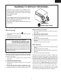
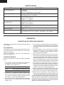
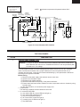
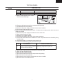
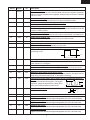
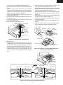
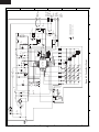
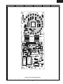
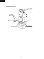
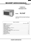
R-21JCA
SUPPLEMENTAL SERVICE MANUAL
S8213R21HCPA/
LIGHT DUTY
COMMERCIAL
MICROWAVE OVEN
1000W/ R-21JCA
TIME GUIDE FOR ONE
15 - 30 sec.
Bagel, Roll
Muffin, Pastry
Pie Slice
40 50
30 D E
20 C
10
2 - 3 min.
Casserole, Stew
Chili, Chowder
Popcorn, 3.5 oz.
1
F
G
1.5
I
2
J
K
L
M
ERCIA
N
L MICR
O
T
WAVE O
VEN
R-21JCA
H
B
A
0
COMM
MODEL
SERVING
30 - 60 sec.
Hot Dog
Pizza Slice
Small Sandwich
1 - 2 min.
Beverage, Soup
Large Sandwich
Popcorn, 1.5 oz.
6
O
S
R
Q
5
INSTRUCTIO
P
2.5
In the interest of user-safety the oven should be restored to its original
condition and only parts identical to those specified should be used.
3
4
NS
With the door
closed,turn the
timer to
the desired
time. Oven
will begin
operating immedia
tely.
WARNING TO SERVICE PERSONNEL: Microwave ovens contain circuitry capable of producing very high voltage and
current. Contact with the following parts may result in a
severe, possibly fatal, electrical shock. (High Voltage Capacitor, High Voltage Power Transformer, Magnetron, High Voltage Rectifier Assembly, High Voltage Harness etc..)
To shut oven
off manually,return
to "0".
timer
This is a supplemental Service Manual for Model R-21JCA. This model is quite similar to base
model R-21HC. Use this supplemental manual together with the Base Model Service Manual
(Reference No. is S7813R21HCP//) for complete operation, service information, etc..
TABLE OF CONTENTS
Page
PRECAUTIONS TO BE OBSERVED BEFORE AND DURING SERVICING TO
AVOID POSSIBLE EXPOSURE TO EXCESSIVE MICROWAVE ENERGY ................... INSIDE FRONT COVER
BEFORE SERVICING ...................................................................................................... INSIDE FRONT COVER
WARNING TO SERVICE PERSONNEL ................................................................................................................ 1
MICROWAVE MEASUREMENT PROCEDURE ................................................................................................... 2
FOREWORD AND WARNING ............................................................................................................................... 3
PRODUCT SPECIFICATIONS .............................................................................................................................. 4
OPERATION .......................................................................................................................................................... 4
SCHEMATIC DIAGRAM ........................................................................................................................................ 5
TEST PROCEDURE .............................................................................................................................................. 5
CONTROL PANEL ASSEMBLY ............................................................................................................................ 8
COMPONENT REPLACEMENT AND ADJUSTMENT PROCEDURE ................................................................ 11
CONTROL PANEL CIRCUIT ............................................................................................................................... 14
PRINTED WIRING BOARD ................................................................................................................................. 15
PARTS LIST ........................................................................................................................................................ 16
PACKING AND ACCESSORIES ......................................................................................................................... 20
This document has been published to be used for after
sales service only.
The contents are subject to change without notice.
SHARP CORPORATION
23
R-21JCA
PRECAUTIONS TO BE OBSERVED BEFORE AND
DURING SERVICING TO AVOID POSSIBLE
EXPOSURE TO EXCESSIVE MICROWAVE
ENERGY
(a) Do not operate or allow the oven to be operated with the door open.
(b) Make the following safety checks on all ovens to be serviced before activating the magnetron or other
microwave source, and make repairs as necessary: (1) interlock operation, (2) proper door closing, (3)
seal and sealing surfaces (arcing, wear, and other damage), (4) damage to or loosening of hinges and
latches, (5) evidence of dropping or abuse.
(c) Before turning on microwave power for any service test or inspection within the microwave generating
compartments, check the magnetron, wave guide or transmission line, and cavity for proper alignment,
integrity, and connections.
(d) Any defective or misadjusted components in the interlock, monitor, door seal, and microwave
generation and transmission systems shall be repaired, replaced, or adjusted by procedures described
in this manual before the oven is released to the owner.
(e) A microwave leakage check to verify compliance with the Federal Performance Standard should be
performed on each oven prior to release to the owner.
BEFORE SERVICING
Before servicing an operative unit, perform a microwave emission check as per the Microwave
Measurement Procedure outlined in this service manual.
If microwave emissions level is in excess of the specified limit, contact SHARP ELECTRONICS
CORPORATION immediately @1-800-237-4277.
If the unit operates with the door open, service person should 1) tell the user not to operate the oven
and 2) contact SHARP ELECTRONICS CORPORATION and The Food and Drug Administration's
Center for Devices and Radiological Health immediately.
Service personnel should inform SHARP ELECTRONICS CORPORATION of any certified unit found
with emissions in excess of 4mW/cm2. The owner of the unit should be instructed not to use the unit
until the oven has been brought into compliance.
24
R-21JCA
WARNING TO SERVICE PERSONNEL
Microwave ovens contain circuitry capable of producing very high voltage and current, contact with
following parts may result in a severe, possibly
fatal, electrical shock.
(Example)
High Voltage Capacitor, High Voltage Power Transformer, Magnetron, High Voltage Rectifier Assembly, High Voltage Harness etc..
Read the Service Manual carefully and follow all
instructions.
Don't Touch !
Danger High Voltage
When the testing is completed,
1. Disconnect the power supply cord, and then remove
outer case.
2. Open the door and block it open.
3. Discharge high voltage capacitor.
4. Reconnect the leads to the primary of the power
transformer.
5. Reinstall the outer case (cabinet).
6. Reconnect the power supply cord after the outer case is
installed.
7. Run the oven and check all functions.
Before Servicing
1. Disconnect the power supply cord
outer case.
2. Open the door and block it open.
3. Discharge high voltage capacitor.
, and then remove
WARNING:RISK OF ELECTRIC SHOCK.
DISCHARGE THE HIGH-VOLTAGE
CAPACITOR BEFORE SERVICING.
The high-voltage capacitor remains charged about 60
seconds after the oven has been switched off. Wait for 60
seconds and then short-circuit the connection of the highvoltage capacitor (that is the connecting lead of the highvoltage rectifier) against the chassis with the use of an
insulated screwdriver.
After repairing
1. Reconnect all leads removed from components during
testing.
2. Reinstall the outer case (cabinet).
3. Reconnect the power supply cord after the outer case is
installed.
4. Run the oven and check all functions.
Whenever troubleshooting is performed the power supply
must be disconnected. It may in, some cases, be necessary
to connect the power supply after the outer case has been
removed, in this event,
1. Disconnect the power supply cord, and then remove
outer case.
2. Open the door and block it open.
3. Discharge high voltage capacitor.
4. Disconnect the leads to the primary of the power
transformer.
5. Ensure that the leads remain isolated from other
components and oven chassis by using insulation tape.
6. After that procedure, reconnect the power supply cord.
Microwave ovens should not be run empty. To test for the
presence of microwave energy within a cavity, place a cup
of cold water on the oven turntable, close the door and set
the power to HIGH and set the microwave timer for two (2)
minutes. When the two minutes has elapsed (timer at zero)
carefully check that the water is now hot. If the water
remains cold carry out Before Servicing procedure and reexamine the connections to the component being tested.
When all service work is completed and the oven is fully
assembled, the microwave power output should be checked
and a microwave leakage test should be carried out.
1
R-21JCA
MICROWAVE MEASUREMENT PROCEDURE
A. Requirements:
1) Microwave leakage limit (Power density limit): The power density of microwave radiation emitted by a microwave oven
should not exceed 1mW/cm2 at any point 5cm or more from the external surface of the oven, measured prior to acquisition
by a purchaser, and thereafter (through the useful life of the oven), 5 mW/cm2 at any point 5cm or more from the external
surface of the oven.
2) Safety interlock switches: Primary interlock relay and door sensing switch shall prevent microwave radiation emission
in excess of the requirement as above mentioned, secondary interlock switch shall prevent microwave radiation emission
in excess of 5 mW/cm2 at any point 5cm or more from the external surface of the oven.
B. Preparation for testing:
Before beginning the actual measurement of leakage, proceed as follows:
1) Make sure that the actual instrument is operating normally as specified in its instruction booklet.
Important:
Survey instruments that comply with the requirement for instrumentation as prescribed by the performance standard for
microwave ovens, 21 CFR 1030.10(c)(3)(i), must be used for testing.
2) Place the oven tray in the oven cavity.
3) Place the load of 275±15 ml (9.8 oz) of tap water initially at 20±5˚C (68˚F) in the center of the oven cavity.
The water container shall be a low form of 600 ml (20 oz) beaker with an inside diameter of approx. 8.5 cm (3-1/2 in.)
and made of an electrically nonconductive material such as glass or plastic.
The placing of this standard load in the oven is important not only to protect the oven, but also to insure that any leakage
is measured accurately.
4) Set the cooking control on Full Power Cooking Mode.
5) Close the door and select a cook cycle of several minutes. If the water begins to boil before the survey is completed,
replace it with 275 ml of cool water.
C. Leakage test:
Closed-door leakage test (microwave measurement)
1) Grasp the probe of the survey instrument and hold it perpendicular to the gap between the door and the body of the oven.
2) Move the probe slowly, not faster than 1 in./sec. (2.5 cm/sec.) along the gap, watching for the maximum indication on
the meter.
3) Check for leakage at the door screen, sheet metal seams and other accessible positions where the continuity of the metal
has been breached (eg., around the switches, indicator, and vents).
While testing for leakage around the door pull the door away from the front of the oven as far as is permitted by the closed
latch assembly.
4) Measure carefully at the point of highest leakage and make sure that the highest leakage is no greater than 4mW/cm2,
and that the secondary interlock switch does turn the oven OFF before any door movement.
NOTE: After servicing, record data on service invoice and microwave leakage report.
2
R-21JCA
SERVICE MANUAL
LIGHT DUTY
COMMERCIAL
MICROWAVE OVEN
R-21JCA
FOREWORD
This Manual has been prepared to provide Sharp Electronics Corp. Service Personnel with Operation and Service
Information for the SHARP MICROWAVE OVEN, R-21JCA.
The model R-21JCA is quite similar to base model R-21HC (Refer No. is S7813R21HCP//).
It is recommended that service personnel carefully study the entire text of this manual and the base model's manual so
that they will be qualified to render satisfactory customer service.
Check the interlock switches and the door seal carefully. Special attention should be given to avoid electrical shock and
microwave radiation hazard.
WARNING
Never operate the oven until the following points are ensured.
(A) The door is tightly closed.
(B) The door brackets and hinges are not defective.
(C) The door packing is not damaged.
(D) The door is not deformed or warped.
(E) There is no other visible damage with the oven.
Servicing and repair work must be carried out only by trained service personnel.
DANGER
Certain initial parts are intentionally not grounded and present a risk of electrical shock only during servicing.
Service personnel - Do not contact the following parts while the appliance is energized;
High Voltage Capacitor, Power Transformer, Magnetron, High Voltage Rectifier Assembly, High Voltage
Harness;
If provided, Vent Hood, Fan assembly, Cooling Fan Motor.
All the parts marked “*” on parts list are used at voltages more than 250V.
Removal of the outer wrap gives access to voltage above 250V.
All the parts marked “∆” on parts list may cause undue microwave exposure, by themselves, or when they are
damaged, loosened or removed.
SHARP ELECTRONICS CORPORATION
SHARP PLAZA, MAHWAH,
NEW JERSEY 07430-2135
3
R-21JCA
SPECIFICATION
ITEM
DESCRIPTION
Power Requirements
120 Volts
14 Amperes
60 Hertz / Single phase, 3 wire grounded
Power Output
1000 watts (IEC 705 Test Procedure)
Operating frequency of 2450MHz
Case Dimensions
Width 20-1/2" (520mm)
Height 12-1/8" (309mm)
Depth 16"
(406mm)
Cooking Cavity Dimensions
(1.0 Cubic Feet )
Width 13-7/8" (353mm)
Height 8-1/8" (207mm)
Depth 14-5/8" (370mm)
Control Complement
Light Up Dial (6 minutes)
No cooking control
Oven Cavity Light
Yes
Safety Standard
UL Listed
FCC Authorized
DHHS Rules, CFR, Title 21, Chapter 1, Subchapter J, NSF Certified
OPERATION
DESCRIPTION OF OPERATING SEQUENCE
The following is a description of component functions during
oven operation.
4. The microwave energy produced by the magnetron is
channelled through the waveguide into the cavity feedbox, and then into the cavity where the food is placed to
be cooked.
5. Upon completion of the cooking time, the power
transformer, oven lamp, etc. are turned off, and the
generation of microwave energy is stopped. The oven
will revert to the OFF condition.
6. When the door is opened during a cook cycle, monitor
switch, door sensing switch, secondary interlock switch,
relay (RY2) and primary interlock relay(RY1) are activated
with the following results. The circuits to the antenna
motor, the cooling fan motor, the oven lamp and the high
voltage components are de-energized, and the cooking
program will be canceled when the door was opened.
7. The monitor switch electrically monitors the operation of
the secondary interlock switch and primary interlock
relay(RY1) and is mechanically associated with the door
so that it will function in the following sequence.
(1) When the door opens from the closed position, the primary
interlock relay(RY1) and secondary interlock switch open
their contacts. Then the monitor switch contacts close.
(2) When the door is closed from the open position, the
monitor switch contacts open first. Then the contacts of the
secondary interlock switch and door sensing switch close.
If the secondary interlock switch and primary interlock relay (RY1)
fail with the contacts closed when the door is opened, the closing
of the monitor switch contacts will form a short circuit through the
monitor fuse, secondary interlock switch, and primary interlock
relay(RY1), causing the monitor fuse to blow.
OFF CONDITION
Closing the door activates door sensing switch and secondary interlock switch. (In this condition, the monitor switch
contacts are opened.)
When oven is plugged in, 120 volts A.C. is supplied to the
control unit (Figure O-1).
COOKING CONDITION
When the Light Up Dial is turned, the following operations
occur:
1. The contacts of relays are closed and components
connected to the relays are turned on as follows.
(For details, refer to Figure O-2)
RELAY
RY-1
RY-2
CONNECTED COMPONENTS
Oven lamp/ Antenna motor/ Fan motor
Power transformer
2. 120 volts A.C. is supplied to the primary winding of the
power transformer and is converted to about 3.2 volts
A.C. output on the filament winding, and approximately
2150 volts A.C. on the high voltage winding.
3. The filament winding voltage heats the magnetron
filament and the H.V. winding voltage is sent to a voltage
doubler circuit.
4
R-21JCA
SCHEMATIC
NOTE: CONDITION OF OVEN
1. LIGHT UP DIAL OFF.
2. DOOR CLOSED.
THERMAL
THERMAL
CUT-OUT
CUT-OUT
125˚C (OVEN) 145˚C (MAG.)
MONITOR SWITCH
RY2
COOK
RELAY
RY1
PRIMARY
INTERLOCK
RELAY
AC120V
60 Hz
CONTROL UNIT
A3
A1
OL
DOOR SENSING
SWITCH
OVEN
LAMP
FM
FAN
MOTOR
CAPACITOR
0.94 µF
2400V
MAGNETRON
POWER
TRANSFORMER
A5
RECTIFIER
MONITOR
FUSE 20A
Indicates components with potential above 250 V.
NOTE:
AM
ANTENNA
MOTOR
SECONDARY
INTERLOCK SWITCH
Figure O-1 Oven Schematic-OFF Condition
TEST PROCEDURES
PROCEDURE
LETTER
I
COMPONENT TEST
CONTROL PANEL ASSEMBLY TEST
WARNING : To prevent an electric shock do not touch the electrical parts and the printed wiring
board. Because the control unit is "TRANSLESS CIRCUIT" and many electrical parts
are used at A.C. line voltage.
The control panel consists of circuits including semiconductors such as LSI, ICs, etc. Therefore,
unlike conventional microwave ovens, proper maintenance cannot be performed with only a
voltmeter and ohmmeter. In this service manual troubleshooting by unit replacement is described
according to the symptoms indicated.
Before testing,
1) Disconnect the power supply cord and then remove outer case.
2) Open the door and block it open.
3) Discharge high voltage capacitor.
4) Disconnect the leads to the primary of the power transformer.
5) Ensure that these leads remain isolated from other components and oven chassis by using
insulation tape.
6) After that procedure, re-connect the power supply cord.
1. Control Panel
The following symptoms indicate a defective control unit.
1-1 In connection with LEDs
a) At a certain LED, all or some LEDs do not light up.
b) At a certain LED, brightness is low.
c) Only one LED does not light up.
d) All or some LEDs continue to light up.
e) A certain group of LEDs do not light up.
f) The LEDs flicker.
5
R-21JCA
TEST PROCEDURES
PROCEDURE
LETTER
COMPONENT TEST
1-2 Other possible troubles caused by defective control unit.
a) Buzzer does not sound or continues to sound.
b) Clock is not possible.
c) Cooking time can not be set.
When testing is completed,
1) Disconnect the power supply cord and then remove outer case.
2) Open the door and block it open.
3) Discharge high voltage capacitor.
4) Reconnect all leads removed from components during testing.
5) Re-install the outer case (cabinet).
6) Reconnect the power supply cord after the outer case is installed.
7) Run the oven and check all functions.
J
RELAY TEST
1. Disconnect the power supply cord and then remove outer case.
2. Open the door and block it open.
3. Discharge high voltage capacitor.
4. Disconnect the leads to the primary of the power transformer.
5. Ensure that these leads remain isolated from other components and oven chassis by using insulation
tape.
6. After that procedure, re-connect the power supply cord.
7. Remove the outer case and check voltage between Pin No. 5 of the 3 pin connector (A) and the
common terminal of the relay RY1 on the control unit with an A.C. voltmeter.
The meter should indicate 120 volts, if not check oven circuit.
RY1 AND RY2 Relay Test
These relays are operated by D.C. voltage
Check voltage at the relay coil with a D.C. voltmeter during the microwave cooking operation.
DC. voltage indicated ................. Defective relay.
DC. voltage not indicated ........... Check diode which is connected to the relay coil. If diode is
good, control unit is defective.
RELAY SYMBOL
OPERATIONAL VOLTAGE
CONNECTED COMPONENTS
RY1
Approx. 19.2V D.C.
Oven lamp / Antenna motor / Cooling fan motor
RY2
Approx. 19.9V D.C.
Power transformer
The voltage under the condition when all LEDs light up.
8. Disconnect the power supply cord and then remove outer case.
9. Open the door and block it open.
10.Discharge high voltage capacitor.
11.Reconnect all leads removed from components during testing.
12.Re-install the outer case (cabinet).
13.Reconnect the power supply cord after the outer case is installed.
14.Run the oven and check all functions.
K
FOIL PATTERN ON THE PRINTED WIRING BOARD TEST
To protect the electronic circuits, this model is provided with a fine foil pattern added to the primary on
the PWB, this foil pattern acts as a fuse.
1. Foil pattern check and repairs.
1) Disconnect the power supply cord and then remove outer case.
2) Open the door and block it open.
3) Discharge high voltage capacitor.
4) Follow the troubleshooting guide given below for repair.
6
R-21JCA
TEST PROCEDURES
PROCEDURE
LETTER
COMPONENT TEST
STEPS
OCCURRENCE
CAUSE OR CORRECTION
1
Only pattern at "a" is broken.
*Insert jumper wire J1 and solder.
2
Pattern at "a" and "b" are broken.
*Insert the coil RCILF2003YAZZ between "c" and "d".
5) Make a visual inspection of the varistor.
Check for burned damage.
c
5
RY2
RY1
a
VRS1
J1
d
CNA
b
6) Reconnect all leads removed from components during testing.
7) Re-install the outer case (cabinet).
8) Reconnect the power supply cord after the outer case is installed.
9) Run the oven and check all function.
2. Follow the troubleshooting guide given below, if indicator does not light up after above check and
repairs are finished.
1) Disconnect the power supply cord and then remove outer case.
2) Open the door and block it open.
3) Discharge high voltage capacitor.
4) Disconnect the leads to the primary of the power transformer.
5) Ensure that these leads remain isolated from other components and oven chassis by using
insulation tape.
6) After that procedure, re-connect the power supply cord.
7) Follow the troubleshooting guide given below for repair.
STEPS
1
OCCURRENCE
CAUSE OR CORRECTION
The rated AC voltage is not present between
Pin No. 5 of the 3-pin connector (A) and the
common terminal of the relay RY1.
Check supply voltage and oven power cord.
8) Disconnect the power supply cord and then remove outer case.
9) Open the door and block it open.
10) Discharge high voltage capacitor.
11) Reconnect all leads removed from components during testing.
12) Re-install the outer case (cabinet).
13) Reconnect the power supply cord after the outer case is installed.
14) Run the oven and check all functions.
7
R-21JCA
CONTROL PANEL ASSEMBLY
OUTLINE OF CONTROL PANEL
4) Reset Circuit
A circuit to generate a signals which resets the LSI to the
initial state when power is supplied.
Control Unit
Control unit consists of LSI, power source circuit, synchronizing signal circuit, reset circuit, buzzer circuit, encoder
circuit and indicator circuit.
5) Buzzer Circuit
The buzzer is responsive to signals from the LSI to emit
audible sounds (completion sound).
1) LSI
This LSI controls the encoder signal, relay driving signal
for oven function, buzzer signal and LED signal.
6) Door Sensing Switch
A switch to “tell” the LSI if the door is open or closed.
2) Power Source Circuit
This circuit generates voltage necessary in the control
unit.
Symbol
Voltage
Application
VC
+5V (*)
LSI(I-1)
VR
+20V (*)
RELAY(RY1, RY2)
7) Relay Circuit
To drive the magnetron, fan motor, antenna motor and
light the oven lamp.
8) Encoder
The encoder generates the pulse signal, and the pulse
signal is sent to the LSI.
(*) The voltage under the condition when all LEDs light
up. The voltage VR will vary according to the quantity
of the LEDs which light up.
9) Indicator Circuit
Indicator elements are the Light-emitting diodes (LD1LD20).
This circuit consists of 4-digits and 5 segments.
3) Synchronizing Signal Circuit
The power source synchronizing signal is available in
order to compose a basic standard time in the clock
circuit. It accompanies a very small error because it
works on commercial frequency.
DESCRIPTION OF LSI
LSI (IXA167DR)
The I/O signal of the LSI (IXA167DR) are detailed in the following table.
Pin No.
Signal
I/O
Description
1
D3
OUT
Segment data signal.
Signal is input to the cathodes of the light-emitting diodes (LD1, LD6, LD11 and LD16).
2
D4
OUT
Digit selection signal.
Signal is input to the anodes of the light-emitting diodes (LD16 - LD20).
3
D5
OUT
Digit selection signal.
Signal is input to the anodes of the light-emitting diodes (LD11 - LD15).
4
D6
OUT
Digit selection signal.
Signal is input to the anodes of the light-emitting diodes (LD6 - LD10).
5
D7
OUT
Digit selection signal.
Signal is input to the anodes of the light-emitting diodes (LD1 - LD5).
6
P20
IN
Connected to VDD terminal.
7
8
P21
P22
IN
IN
Connected to VSS terminal.
Signal coming from encoder.
When the encoder is turned, the contacts of encoder make pulse signals. And
pulse signals are input into P22.
8
R-21JCA
Pin No.
Signal
I/O
Description
9
RESET
IN
Auto clear terminal.
Signal is input to reset the LSI to the initial state when power is applied. Temporarily
set to "L" level the moment power is applied, at this time the LSI is reset. Thereafter
set at "H" level.
10
CNVSS
IN
Power source voltage.
The power source voltage to drive the LSI is input to CNVSS terminal.
11
XOUT
OUT
12
XIN
IN
Internal clock oscillation frequency input setting.
The internal clock frequency is set by inserting the ceramic filter oscillation circuit with
respect to XOUT terminal.
13
VSS
IN
Power source voltage: 0V.
The power source voltage to drive the LSI is input to VSS terminal. Connected to VC.
14
VDD
IN
Power source voltage: +5V.
The power source voltage to drive the LSI is input to VDD terminal.
15
16
N.F
INT0
IN
IN
Connected to VSS terminal.
Signal coming from encoder.
Signal similar to P22. Pulse signals are input into INT0.
17
INT1
IN
Signal to synchronize LSI with commercial power source frequency.
This is basic timing for all real time
processing of LSI.
Internal clock oscillation frequency control output.
Output to control oscillation input of XIN.
H : +5V
L: 0V
16.7 msec
18
AIN0
IN
Input signal which communicates the door open/close information to LSI.
Door closed; "L" level signal.
Door opened; "H" level signal.
AIN1-AIN3
IN
Terminal to change functions according to the model.
Signal in accordance with the model in operation is applied to set up its function.
22
23
P00
P01
OUT
OUT
Terminal not used.
Magnetron high-voltage circuit driving signal.
To turn on and off the cook relay (RY2). In 100% power operation, the signals hold "H"
level during microwave cooking and "L" level while not cooking.
24
P02
OUT
Oven lamp, turntable motor and fan motor driving signal(Square Waveform :
16.7 msec
60Hz).
H
To turn on and off shut-off relay (RY1). The square
waveform voltage is delivered to the relay (RY1)
L
driving circuit and relay(RY2) control circuit.
During cooking
25
P03
OUT
Signal to sound buzzer.
Completion sound.
19-21
2.0 sec
H: +5V
L:
26
27-29
0V
P10
P11-P13
OUT
OUT
Terminal not used.
Segment data signal.
Signal is input to the cathodes of the light-emitting diodes (LD5, LD10, LD15 and LD20).
30
D0
OUT
Segment data signal.
Signal is input to the cathodes of the light-emitting diodes (LD4, LD9, LD14 and LD19).
31
D1
OUT
Segment data signal.
Signal is input to the cathodes of the light-emitting diodes (LD3, LD8, LD13 and LD18).
32
D2
OUT
Segment data signal.
Signal is input to the cathodes of the light-emitting diodes (LD2, LD7, LD12 and LD17).
9
R-21JCA
SERVICING
1. Precautions for Handling Electronic Components
This unit uses CMOS LSI in the integral part of the
circuits. When handling these parts, the following
precautions should be strictly followed. CMOS LSI have
extremely high impedance at its input and output
terminals. For this reason, it is easily influenced by the
surrounding high voltage power source, static electricity
charge in clothes, etc., and sometimes it is not fully
protected by the built-in protection circuit.
In order to protect CMOS LSI.
1) When storing and transporting, thoroughly wrap them
in aluminium foil. Also wrap PW boards containing
them in aluminium foil.
2) When soldering, ground the technician as shown in
the figure and use grounded soldering iron and work
table.
5) Re-connect the power supply cord after the outer
case is installed.
6) Run the oven and check all functions.
A. On some models, the power supply cord between the
touch control panel and the oven itself is so short that the
two can't be separated. For those models, check and
repair all the controls (sensor-related ones included) of
the touch control panel while keeping it connected to the
oven.
B. On some models, the power supply cord between the
touch control panel and the oven proper is so long
enough that they may be separated from each other. For
those models, therefore, it is possible to check and repair
the controls of the touch control panel while keeping it
apart from the oven proper; in this case you must short
both ends of the door sensing switch (on PWB) of the
touch control panel with a jumper, which brings about an
operational state that is equivalent to the oven door
being closed. As for the sensor-related controls of the
touch control panel, checking them is possible if the
dummy resistor(s) with resistance equal to that of the
controls are used.
(2) Servicing the touch control panel with power supply
from an external power source:
Disconnect the touch control panel completely from the
oven proper, and short both ends of the door sensing
switch (on PWB) of the touch control panel, which brings
about an operational state that is equivalent to the oven
door being closed. Connect an external power source to
the power input terminal of the touch control panel, then
it is possible to check and repair the controls of the touch
control panel; it is also possible to check the sensorrelated controls of the touch control panel by using the
dummy resistor(s).
approx. 1M ohm
2. Shapes of Electronic Components
C
B
E
Transistor
KTA1504SGRRTK
KRC105S
KRA101S
KRC101S
Transistor
KTC3198A
E
CB
3. Servicing of Touch Control Panel
We describe the procedures to permit servicing of the
touch control panel of the microwave oven and the
precautions you must take when doing so. To perform
the servicing, power to the touch control panel is available
either from the power line of the oven itself or from an
external power source.
(1) Servicing the touch control panel with power supply
of the oven :
CAUTION:
THE HIGH VOLTAGE TRANSFORMER OF THE MICROWAVE OVEN IS STILL LIVE DURING SERVICING AND PRESENTS A HAZARD .
Therefore, before checking the performance of the touch
control panel,
1) Disconnect the power supply cord and then remove
outer case.
2) Open the door and block it open.
3) Discharge high voltage capacitor.
4) Disconnect the leads to the primary of the power
transformer.
5) Ensure that these leads remain isolated from other
components and oven chassis by using insulation
tape.
6) After that procedure, re-connect the power supply
cord.
After checking the performance of the touch control
panel,
1) Disconnect the power supply cord.
2) Open the door and block it open.
3) Re-connect the leads to the primary of the power
transformer.
4) Re-install the outer case (cabinet).
4. Servicing Tools
Tools required to service the touch control panel
assembly.
1) Soldering iron: 30W
(It is recommended to use a soldering iron with a
grounding terminal.)
2) Oscilloscope: Single beam, frequency range: DC 10MHz type or more advanced model.
3) Others: Hand tools
5. Other Precautions
1) Before turning on the power source of the control unit,
remove the aluminium foil applied for preventing
static electricity.
2) Connect the connector of the key unit to the control
unit being sure that the lead wires are not twisted.
3) After aluminium foil is removed, be careful that
abnormal voltage due to static electricity etc. is not
applied to the input or output terminals.
4) Attach connectors, electrolytic capacitors, etc. to
PWB, making sure that all connections are tight.
5) Be sure to use specified components where high
precision is required.
10
R-21JCA
COMPONENT REPLACEMENT AND ADJUSTMENT PROCEDURE
WARNING AGAINST HIGH VOLTAGE:
Microwave ovens contain circuitry capable of producing very high voltage and current, contact with following parts may
result in severe, possibly fatal, electric shock.
(Example)
High Voltage Capacitor, Power Transformer, Magnetron, High Voltage Rectifier Assembly, High Voltage Harness etc..
WARNING:
Avoid possible exposure to microwave energy. Please follow the instructions below before
operating the oven.
1. Disconnect the power supply cord.
2. Visually check the door and cavity face plate for damage
(dents, cracks, signs of arcing etc.).
3. The door gasket or seal is damaged.
4. The door is bent or warped.
5. There are defective parts in the door interlock system.
6. There are defective parts in the microwave generating
and transmission assembly.
7. There is visible damage to the oven.
Carry out any remedial work that is necessary before
operating the oven.
Do not operate the oven if any of the following conditions
exist;
1. Door does not close firmly.
2. Door hinge, support or latch hook is damaged.
Do not operate the oven:
1. Without the RF gasket (Magnetron).
2. If the wave guide or oven cavity are not intact.
3. If the door is not closed.
4. If the outer case (cabinet) is not fitted.
WARNING FOR WIRING
To prevent an electric shock, take the following precautions.
1. Before wiring,
1) Disconnect the power supply cord.
2) Open the door and block it open.
3) Discharge the high voltage capacitor and wait for 60
seconds.
2. Don’t let the wire leads touch to the followiong parts;
1) High voltage parts:
Magnetron, High voltage transformer, High voltage
capacitor and High voltage rectifier assembly.
2) Hot parts:
Oven lamp, Magnetron, High voltage transformer,
and Oven cavity.
3) Sharp edge:
Bottom plate, Oven cavity, Waveguide flange,
Chassis support and other metallic plate.
4) Movable parts (to prevent a fault)
Fan blade, Fan motor, Switch, Switch lever and
antenna motor.
3. Do not catch the wire leads in the outer case cabinet.
4. Insert the positive lock connector until its pin is locked
and make sure that the wire leads do not come off even
if the wire leads are pulled.
5. To prevent an error function, connect the wire leads
correctly, referring to the Pictorial Diagram.
Please refer to ‘OVEN PARTS, CABINET PARTS, CONTROL PANEL PARTS, DOOR PARTS’, when carrying out any of
the following removal procedures:
DOOR PARTS REMOVAL
CHOKE COVER
1. Disconnect the power supply cord.
2. Open the door slightly.
3. Insert a putty knife (thickness of about 0.5mm) into the
gap between the choke cover and door frame as shown
in Figure C-6 to free engaging parts.
4. Pry the choke cover by inserting a putty knife as shown
in Figure C-6.
5. Release choke cover from door panel.
6. Now choke cover is free.
NOTE: When carrying out any repair to the door, do not
bend or warp the slit choke (tabs on the door
panel assembly) to prevent microwave leakage.
Choke Cover
Putty Knife
Door Frame
Figure C-6. Door Disassembly
11
R-21JCA
7. Release two (2) pins of door panel from two (2) holes of
upper and lower oven hinges by lifting up.
8. Now, door sub assembly is free from oven cavity.
NOTE: After any service to the door;
(A) Make sure that door sensing switch and secondary
interlock switch are operating properly. (Refer to
chapter "Test Procedures".).
(B) An approved microwave survey meter should be
used to assure compliance with proper microwave
radiation emission limitation standards. (Refer to
Microwave Measurement Procedure.)
DOOR PANEL REMOVAL
9. Remove the four (4) screws holding the door panel to the
door frame.
10.Release door panel from seven (7) tabs of door frame by
sliding door panel downward.
11.Now, the door panel is free.
After any service, make sure of the following :
1. Door latch heads smoothly catch latch hook through
latch holes and that latch head goes through center of
latch hole.
2. Deviation of door alignment from horizontal line of cavity
face plate is to be less than 1.0mm.
3. Door is positioned with its face pressed toward cavity
face plate.
4. Check for microwave leakage around door with an
approved microwave survey meter. (Refer to Microwave
Measurement Procedure.)
Note: The door on a microwave oven is designed to act as
an electronic seal preventing the leakage of microwave
energy from oven cavity during cook cycle. This
function does not require that the door be air-tight,
moisture (condensation)-tight or light-tight. Therefore,
occasional appearance of moisture, light or sensing
of gentle warm air movement around oven door is not
abnormal and do not in themselves indicate a leakage
of microwave energy from oven cavity.
DOOR HANDLE REMOVAL
12.Release the latch spring from the tab of the latch angle
assembly.
13.Remove the two (2) screws holding the door handle and
the latch angle assembly through the door frame.
14.Now, door handle is free.
LATCH HEADS REMOVAL
15.Remove the one (1) screw holding the latch angle
assembly to the door frame.
16.Remove the latch angle assembly together with the latch
lever, latch spring and the upper and lower latch heads
from the door frame.
17.Release the latch lever together with the latch spring and
the latch heads from the latch angle assembly.
18.Release the two (2) latch heads from the latch lever.
19.Now, the upper and lower latch heads are free.
FRONT DOOR GLASS OR SEALER PLATE REMOVAL
(After DOOR PANEL REMOVAL)
12.Remove the four (4) screws holding the glass stopper U
to the door frame and remove the glass stopper U.
13.Remove the two (2) screws holding the glass stopper R
to the door frame and remove the glass stopper R.
14.Slide the front door glass and the sealer plate left at first
and then slide upwards to release them from the tabs
holding it.
17.Now, the front door glass or the sealer plate free.
Pin
Upper
Oven
Hinge
Upper Oven
Hinge
DOOR CASE REMOVAL
(After DOOR PANEL REMOVAL)
12.Straighten all tabs of the door case holding the door case
to the door frame.
13.Release door case from the door frame.
17.Now, the door case is free
NOTE: At this moment, the door badge is attached on the
door case.
Door
Panel
Lower
Oven
Hinge
Slit
Chok
Choke Cover
RE-INSTALL OF THE DOOR
1. Re-install all door parts except the choke cover.
2. Catch two (2) pins of door panel on two (2) holes of upper
and lower oven hinges.
3. Re-install choke cover to door panel by pushing.
Pin
Lower
Oven
Hinge
Figure C-7. Door Replacement
ANTENNA MOTOR SHAFT REPLACEMENT
REMOVAL
3. To discharge the high voltage capacitor, wait for 60
seconds.
4. Remove the antenna motor from the oven cavity bottom
1. Disconnect the power supply cord.
2. Open the door and block it open.
12
R-21JCA
plate, referring to "ANTENNA MOTOR REMOVAL" .
5. Remove the ceramic shelf from the oven cavity bottom
plate.
6. Remove the one (1) screw and the one (1) washer
holding the antenna holder of the stirrer antenna assembly
to the oven cavity bottom plate through the square hole
of the stirrer antenna. Refer to Figure C-8.
7. Release the antenna holder from the one (1) tab of the
oven cavity bottom plate.
8. Remove the stirrer antenna assembly from the oven
cavity bottom plate.
9. Remove the antenna motor shaft from the hole of the
oven cavity bottom plate.
10.Now, the antenna motor shaft is free.
Screw
Washer
3. Hook the hole of the antenna holder on the tab of the
oven cavity bottom plate. Refer to Figure C-10.
4. Insert the antenna holder into the hole of the oven cavity
bottom plate and fit the hole of the antenna holder with
an antenna motor shaft. Refer to Figure C-10.
5. Install the antenna holder to the oven cavity bottom plate
with the one (1) screw and the one (1) washer. Refer to
Figure C-8.
6. Install the antenna motor to the oven cavity bottom plate
with one (1) screw. Refer to Figure C-8.
7. Connect the wire leads to the antenna motor, referring to
the pictorial diagram.
8. Install the base plate cover to the base plate with one (1)
screw.
9. Install the ceramic shelf to the oven cavity bottom plate.
Refer to "INSTALLATION OF CERAMIC SHELF" .
Antenna holder
Square
hole
Stirrer antenna
Tab
To left wall of
oven cavity
Antenna
motor shaft
Flat face
Antenna
motor shaft
Oven cavity
bottom plate
To right wall
of oven cavity
Antenna motor
Flat face
Screw
Antenna holder
Figure C-8. Antenna Motor Shaft Removal
INSTALLATION
1. Install the antenna motor shaft into the hole of the oven
cavity bottom plate, and turn the flat faces of antenna
motor shaft to the left and right side walls of oven cavity
(to fit the stirrer antenna holder). Refer to Figure C-9.
2. Set the direction of the stirrer antenna and antenna
holder so that the hole of the antenna holder fit to the
centre of the stirrer antenna's big blade. Refer to Figure
C-9.
Centre
Hole
Stirrer antenna
Stirrer antenna's
big blade
Figure C-9. Derection of Antenna Motor Shaft and
Stirrer Antenna Assembly
Stirrer antenna assembly
Tab
Antenna
motor shaft
Oven cavity
bottom plate
Antenna holder
Antenna holder
Stirrer antenna
Stirrer antenna
Tab
Tab
Antenna
motor shaft
Antenna
motor shaft
Oven cavity bottom plate
Figure C-10. Stirrer Antenna Assembly Installation
13
AC
A5
VRS1
10G471K
R11
2W 100
R12
1/2W 100K
D1
1
3
14
4
B
C
C2
A
0.1µ/50 V
C3
R63 4.7K
R62 4.7K
3
Model Chg.
9
220µ/16V
5
27K
(40S)
(20S)
LD1
LD1 _ LD20 LTL-1CHE-011A x 20
LD2
(.)
(3M)
(1M)
LD6
LD7
D70
LD11
D74 (6M)
(.)
LD3
7
R10 4.7K
6
C6
5
Q70
KRA101S
4
CF1 4MHz
Q71
KRA101S
INT0
N.F
VDD
VSS
XIN
XOUT
CNVSS
RESET
C60
16
15
14
13
12
11
10
9
R5 1K
Q72
KRA101S
LD16 Q73
D78( . )
KRA101S
D82
LD8
D71
D10
I-1
IXA167DR
14
Q1
C30
4.7K
R21
C20
0.1µ
/50V
ZD1
HZ11A3 x 3
D22
D21
RY1
Q21
KRA101S
Q22
KRC105S
RY2
: IF NOT SPECIFIED 1SS270A
: IF NOT SPECIFIED 0.01µ/50V
: IF NOT SPECIFIED 1/10W 5%
0.1µ/50 V
C31
R31
47K
D30
D20
Q20
KRC101S
4.7K
R22
ZD3
ZD2
R30
4.7K
C21
10µ
/35V
R3
1W 1K
R20 4.7K
ZD5
ZD4
KTC3198A
R2
1W 510 x 2
R1
A3
A1
AC
COM
CN-A3
Pin5mm
Pitch
DOOR
SENSING
SWITCH
120V/60Hz
OVEN LAMP
ANTENNA
MOTOR
FAN MOTOR
POWER
TRANSFORMER
N.O
COM
N.O
5
Figure S-2. Control Unit Circuit
(2M)
D72
(.)
(5M)
LD12
D75 (7M)
LD13
LD4
(4M)
LD10
LD5
LD9
(10M)
D73
LD14
D77 (9M)
LD15
8
25
26
27
28
29
30
31
32
C4
0.1µ/50V
C61
R6
4.7K
Q2
KTA1504
VC
4
D76 (8M)
LD17
D79( . )
LD18
D80( . )
(15M)
LD19
D81( . )
R70
430
LD20
R71
330
D83
R72
240
D84
R73
150
R74
100
10
P03
P10
P11
P12
P13
D0
D1
D2
D85
12
R9
Q40
KRC101S
SP1
C7
P22
P21
P20
D7
D6
D5
D4
D3
13
11
R42
3.3K
R41
1.5K
27K
D11
8
7
6
5
4
3
2
1
R60
10K
2
1000µ/35V
R50
10K
C5
R40
4.7K
27K
R8
3
SW1
R61
10K
D2
D4
(J7)
1N4005E x 4
C1
D3
2.2µ/160VAC
VR
(J5) 6.2K
(J6) 4.7K
ICP1
(J3)
2
(J4) 4.7K
B
(J2) 4.7K
1
0.1µ/50V
G
P02
P01
P00
AIN3
AIN2
AIN1
AIN0
INT1
E
HZ4C1
R7
A
24
23
22
21
20
19
18
17
D
ZD6
F
2
(JF)
1
4.7K
C
HZ6C3 x 2
(J1)
R-21JCA
6
A
B
C
D
H
6
E
F
G
H
R-21JCA
1
2
4
3
5
6
A
A
D80
D76
JP36
JP39
D72
LD2
LD9
JP34
JP35
B
JP37
LD7
LD8
D71
LD3
JP38
LD6
LD5
LD4
D79
B
LD10
D75
SW1
JP33
LD1
LD11
D78
D74
B
JP30
D70
JP31
JP32
D81
D77
D73
A
JP29
C
LD12
LD13
C
D83
JP28
D84
C
JP27
D85
LD14
JP26
JP25
D82
LD15
LD20
JP23
JP24
LD16
LD17
LD18
1
2
3
4
5
6
7
8
9
10
11
12
13
14
LD19
D
D
1
32
8 9
24
JP10
JP12
2
JP11
JP14
CNC
ZD6
JP16
JP17
JP15
16
17
E
JP21
1
JP13
JP18
JP22
JP20
JP19
E
CF1
JP9
JP8
ZD3
SP1
C5
JP6
Q1
ZD2
R2
B
R3
JP4
ZD4
E
ZD5
JP7
ZD1
JP5
R1
JP1
JP2
JP3
C21
D10
R12
D11
D21
C3
C1
D20
F
F
ICP1
D1
D3
1
2
R11
D2
1
5
RY2
RY1
G
WHA
D30
D4
1
2
WHA
VRS1
G
CNA
D22
J1
SW2
H
H
Figure S-3. Printed Wiring Board
1
2
4
3
15
5
6
R-21JCA
PARTS LIST
Note: The parts marked “∆” may cause undue microwave exposure.
The parts marked “*” are used in voltage more than 250V.
REF. NO.
PART NO.
DESCRIPTION
Q'TY
CODE
1
1
1
1
1
1
1
1
1
1
1
1
1
1
1
1
AK
AF
AH
AV
AV
AV
AU
AG
AG
AY
AE
AQ
AP
AK
BM
BN
1
1
1
2
1
AX
AS
AQ
AC
AF
1
1
1
1
1
1
5
BF
BA
AH
BA
AB
AL
AA
1
1
1
1
1
3
1
1
1
1
1
1
1
1
2
1
2
1
1
5
4
1
1
3
1
2
1
1
1
1
1
1
1
BL
—
AF
AF
AF
AC
AC
AG
BA
AY
AQ
AK
AM
BB
AB
AN
AG
AH
AQ
AD
AD
AF
AF
AA
AC
AC
AB
AF
AD
AD
AL
AF
AM
ELECTRIC PARTS
*
*
*
*
∆*
1- 1
1- 2
1- 3
1- 4
1- 5
1- 6
1- 7
1- 8
1- 9
1-10
1-10
1-11
1-12
1-13
1-14
1-15
FFS-BA015WRK0
QSW-MA051WRE0
QSW-MA135WRE0
FACCDA078WRE0
FH-DZA084WRK0
RC-QZA242WRE0
RMOTEA376WRE0
QFSHDA009WRE0
QSOCLA021WRE0
RLMPTA072WRE0
RLMPTA030WRE0
RMOTDA233WRE0
RTHM-A080WRE0
RTHM-A096WRE0
RTRN-A570WRE0
RV-MZA197WRE0
Monitor fuse and monitor switch assembly
Door sensing switch
Secondary interlock switch
Power supply cord
High voltage rectifier assembly
High voltage capacitor
Fan motor
Fuse holder
Oven lamp socket
Oven lamp
Oven lamp (Interchangeable)
Antenna motor
Thermal cut-out 145 deg. (MAG)
Thermal cut-out 125 deg. (OVEN)
Power transformer
Magnetron
CABINET PARTS
22222-
1
2
3
4
5
GCABUA674WRP0
GDAI-A311WRW0
GCOVHA406WRW0
GLEGPA074WRE0
GLEGPA076WRF0
Outer case cabinet
Base plate
Base plate cover
Foot
Leg
3333333-
1
2
2-1
2-2
3
4
5
DPWBFC288WRUZ
FPNLCB434WRK0
HPNLTA137WRE0
GCOVAA260WRP0
TCAUAA076WRR0
JKNBKA606WRM0
XEPSD30P08XS0
Control unit assembly
Panel sub assembly
Timer sheet
C/P case
User caution label
Timer knob
Screw; 3mm X 8mm
CONTROL PANEL PARTS
OVEN PARTS
4- 1
∆ 4- 2
∆
∆
∆
∆
∆
∆
4- 3
4- 4
4- 5
4- 6
4- 7
4- 8
4- 9
4-10
4-11
4-12
4-13
4-14
4-15
4-16
4-17
4-18
4-19
4-20
4-21
4-22
4-23
4-24
4-25
4-26
4-27
4-28
4-29
4-30
4-31
4-32
4-33
FGLSPA062WRE0
*************
MLEVPA227WRF0
MLEVPA228WRF0
MLEVPA229WRF0
MSPRCA108WRE0
MSPRTA191WRE0
PHOK-A121WRFZ
FDUC-A341WRY0
PSKR-A351WRP0
LBNDKA136WRP0
NFANJA029WRE0
PDUC-A697WRF0
FPLT-A007WRY0
PCUSGA504WRP0
PSKR-A348WRW0
GCOVHA404WRE0
LANGFA199WRWZ
NSFTPA035WRFZ
PCLICA032WRE0
PCLICA033WRE0
PCOVPA344WRF0
PCOVPA345WRF0
PCUSGA249WRP0
PCUSUA511WRP0
PCUSUA194WRP0
PCUSUA514WRP0
PDUC-A722WRF0
PFILWA060WRP0
PSHEPA644WRE0
PSKR-A347WRW0
PSKR-A349WRP0
PSKR-A359WRW0
Ceramic shelf
Oven cavity (Not a replaceable part)
Latch switch lever A
Latch switch lever B
Latch switch lever C
Latch lever spring
Switch lever B spring
Latch hook
Steam duct sub assembly
Steam guide
HV capacitor holder
Fan blade
Fan duct
Stirrer antenna assembly
Insertion cushion
Insertion plate A
VCP cap
Chassis support
Antenna motor shaft
Hand clip 4
Hand clip 5
Side splash cover
Back splash cover
Cushion
Cushion
Cushion
Cushion
Air intake duct
Lamp filter
Insertion sheet
Insertion plate B
Steam duct barrier
Air guide
16
R-21JCA
REF. NO.
4-34
4-35
4-36
4-37
4-38
4-39
4-40
4-41
∆
∆
∆
∆
∆
PART NO.
DESCRIPTION
PSPA-A112WRE0
PCUSGA378WRP0
PCUSUA507WRP0
PCUSUA517WRP0
PSHEPA674WRE0
PPACGA171WRE0
PSHEPA673WRE0
PCUSUA518WRP0
Mica washer
Cushion
Cushion
Cushion
Cover
Cushion
S/ film
Cushion
Q'TY
CODE
1
1
1
1
1
1
1
1
AC
AL
AC
AE
AL
AK
AD
AC
1
1
1
1
1
1
1
1
1
6
1
1
1
2
1
1
1
2
1
1
1
4
2
1
1
1
BP
AZ
AB
AW
BQ
AK
AN
AU
BB
AA
AQ
AN
AR
AL
AD
AC
AB
AK
AK
AK
AC
AB
AB
AC
AM
AL
1
1
1
1
1
1
1
1
1
AM
BB
AB
AE
AC
AC
AE
AC
AE
7
2
4
2
2
1
4
2
1
1
12
1
4
AA
AA
AA
AA
AB
AB
AA
AB
AA
AA
AA
AA
AA
DOOR PARTS
5- 1
5-1-1
5-1-2
5-1-3
5-1-4
5-1-4-1
5-1-4-2
5-1-4-3
5-1-4-4
5-1-4-5
5-1-5
5-1-6
5-1-7
5-1-8
5-1-9
5-1-10
5-1-11
5-1-12
5-1-13
5-1-14
5-1-15
5-1-16
5-1-17
5-1-18
5- 2
5- 3
CDORFA804WRK0
FDORFA322WRT0
PSHEPA649WRE0
FANGKA206WRY0
FCOV-A002WRK0
LSTPPA180WRF0
LSTPPA182WRF0
PGLSPA516WRE0
PSLDMA198WREZ
XCPSD40P08000
GWAKPA580WRM0
JHNDMA040WRW0
LANGKA874WRW0
LSTPPA181WRF0
MSPRTA190WRE0
PCUSUA506WRP0
XEPSD40P06000
PSHEPA686WRE0
PSHEPA687WRE0
PCUSGA514WRP0
PCUSUA505WRP0
XEPSD40P08000
XEPSD40P25K00
PCUSUA508WRP0
GCOVHA407WRF0
HBDGCA107WREZ
Door assembly
Door panel assembly
Sealer film
Latch angle assembly
Door case assembly
Glass stopper R
Glass stopper U
Front door glass
Sealer plate
Screw : 4mm x 8mm
Door handle
Handle lever
Latch lever
Latch head
Latch spring
Cushion
Screw : 4mm x 6mm
Panel sheet
Panel sheet
Cushion
Cushion
Screw : 4mm x 8mm
Screw : 4mm x 25mm
Cushion
Choke cover
Door badge
MISCELLANEOUS
666666666-
1
2
3
4
5
6
7
8
9
TINSEA954WRRZ
FW-VZB684WRE0
TCAUAA166WRR0
TCAUAA241WRR0
TCAUAA243WRR0
TCAUAA245WRR0
TMAPCA759WRR0
LHLDWA013WRE0
TCAUAA249WRR0
Instruction book
Main wire harness
DHHS caution label
Monitor caution
Earth caution
Cover caution
Schematic diagram
Purse lock LL
Caution label
7- 1
7- 2
7- 3
7- 4
7- 5
7- 6
7- 7
7- 8
7- 9
7-10
7-11
7-12
7-13
XHPSD40P08K00
XEPSD40P25000
LX-CZA038WRE0
LX-CZA052WRE0
LX-EZA042WRE0
XBPWW40P04000
XFPSD40P08000
XHTSD40P08000
XHPSD30P06000
XHTSD40P08RV0
XOTSD40P12000
XOTSF40P08000
XOTWW40P10000
Screw :
Screw :
Special
Special
Special
Screw :
Screw :
Screw :
Screw :
Screw :
Screw :
Screw :
Screw :
SCREWS,NUTS AND WASHERS
4mm x
4mm x
screw
screw
screw
4mm x
4mm x
4mm x
3mm x
4mm x
4mm x
4mm x
4mm x
8mm
25mm
4mm
8mm
8mm
6mm
8mm
12mm
8mm
10mm
HOW TO ORDER REPLACEMENT PARTS
To have your order filled promptly and correctly, please furnish the following information.
1. MODEL NUMBER
2. REF. NO.
3. PART NO.
4. DESCRIPTION
Order Parts from the authorized SHARP parts Distributor for your area.
Defective parts requiring return should be returned as indicated in the Service Policy.
17
R-21JCA
2
1
4
3
6
5
7-3
7-3
2-1
OVEN AND CABINET PARTS
A
A
7-3
1-10
1-9
4-28
7-13
7-3
6-6
4-9
B
B
4-10
7-13
6-7
4-25
7-6
7-12
4-32
1-4
6-5
1-13
4-26
4-34
7-13
7-1
4-26
6-3
C
4-24
6-4
4-27
1-4
C
4-15
4-14
7-7
4-19
7-7
4-15
4-36
1-1
4-16
4-2
7-9
7-10
1-8
4-40
7-11
D
D
1-12
4-23
4-21
4-24
4-20
4-21
4-22
4-18
7-8
7-7
4-21
4-20
1-7
E
E
4-33
6-9
7-2
4-13
7-4
7-1
7-4
4-29
1-11
7-1
4-31
1-15
7-7
4-6
7-1
1-6
4-3
4-8
4-30
1-3
F
4-12
F
1-1
2-2
4-1
4-7
4-38
4-4
4-20
4-39
1-2
4-11
4-6
4-37
1-5
4-5
7-5
4-20
7-1
4-41
G
4-35
7-11
G
1-14
2-4
4-24
2-4
7-11 x2
2-3
H
4-17
H
2-5
7-8
1
2
7-11
4
3
18
5
6
R-21JCA
2
1
4
3
6
5
CONTROL PANEL PARTS
A
A
3-1
3-5
3-2
B
B
3-5
3-2-1
3-2-2
C
C
3-3
DOOR PARTS
3-4
5-2
5-1-15
5-1-16
D
D
5-1-14
5-1
5-1-2
5-1-12
5-1-16
5-1-18
5-1-4-2
E
5-1-16
5-1-13
5-1-4-5
x4
5-1-4-4
E
5-1-4
5-1-4-3
5-1-1
5-1-4-1
5-1-4-5
x2
5-1-16
5-1-12
5-1-8
F
F
5-1-7
5-1-17
5-1-9
5-1-11
5-3
5-1-3
5-1-8
5-1-17
5-1-5
G
G
5-1-6
MISCELLANEOUS
6-2
6-8
5-1-10
Actual wire harness may be different from illustration.
H
1
2
4
3
19
5
H
6
R-21JCA
PACKING AND ACCESSORIES
TOP PAD ASSEMBLY
(FPADBA385WRK0)
WRAP COVER
(SSAKHA034WRE0)
TRAY HOLDER
DOOR PROTECTION SHEET
(SPADFA435WRE0)
(SPADPA204WRE0)
6-1 INSTRUCTION BOOK
the avity
Into en C
v
O
BOTTOM PAD ASSEMBLY
(FPADBA386WRK0)
PACKING CASE
Not Replaceable Items.
SPAKCD803WREZ
20
R-21JCA
21
R-21JCA
COPYRIGHT © 2002 BY SHARP CORPORATION
ALL RIGHTS RESERVED.
No part of this publication may be reproduced,
stored in retrieval systems, or transmitted in any form
or by any means, electronic, mechanical, photocopying, recording, or otherwise, without prior written permission of the publisher.
'02 SHARP CORP. (8S0.730E) Printed in U.S.A
22