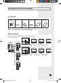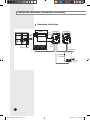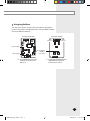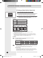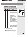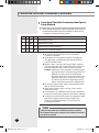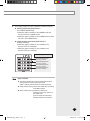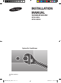
1
INSTALLATION MANUAL Centralized Controller MCM-A202A MCM-A202AU System Air Conditioner E DB98-29495A(1) MCM-A202A_IM_E_29495-1.indd 21 2008-02-14 ソタネト 2:58:30 Safety Precautions This installation manual indicates you to install the centralized controller which is connected to the indoor unit. For installation of other optional accessories, see an appropriate installation manual. WARNING CAUTION Read carefully this installation manual before installation and check whether the centralized controller is installed correctly after installation. Do not attempt to install or repair this centralized controller by yourself. This centralized controller contains no user-serviceable parts. Always consult authorized service personnel for repairs. When moving, consult authorized service personnel for disconnection and installation of the centralized controller. Ensure that the wall is strong enough to support the weight of the centralized controller. The centralized controller must be installed according to the national electrical rules by an installation specialist. When you want to disuse the centralized controller, consult authorized installation center. Do not use inflammable gases near the centralized controller. Do not install the centralized controller in a location where it will come into contact with the combustible gases, machine oil, sulphide gas, etc. Avoid a location where acid/alkali solution or special spray is used. Choose a location that is dry and sunny, but not exposed to direct sunlight. Available temperature is between 0°C(32°F) and 39°C(102°F). Do not spill water into the centralized controller. Do not give tensile strength to the cable to avoid disconnection. Do not press buttons with a pointed thing. Do not connect the power cable to the control terminal. If the centralized controller is installed in a hospital or other special places, it should not affect other electronic devices. E-2 MCM-A202A_IM_E_29495-1.indd 2 2008-02-14 ソタネト 2:57:55 Centralized Controller Installation Accessories Centralized Controller (1) Note Cable-tie (2) Cable Clamp (5) M4x16 Tapped Screw (7) User’s manual (1) Installation manual (1) If you would like to install the centralized controller, you must install the optional transmitter in the outdoor unit. Wiring Diagram Each outdoor unit connected to the same centralized controller must have its own transmitter. Centralized controller Channel 1 Outdoor unit 1 Indoor unit Indoor unit Indoor unit MAIN 0 RMC(1) 0 RMC(2) 0 MAIN 1 RMC(1) 0 RMC(2) 1 MAIN 2 RMC(1) 0 RMC(2) 2 Transmitter Channel 1 Transmitter Channel 1 Outdoor unit 2 Transmitter Indoor unit Indoor unit Indoor unit MAIN 3 RMC(1) 0 RMC(2) 3 MAIN 4 RMC(1) 0 RMC(2) 4 MAIN 5 RMC(1) 0 RMC(2) 5 E-3 MCM-A202A_IM_E_29495-1.indd 3 2008-02-14 ソタネト 2:57:56 Centralized Controller Installation (Continued) Transmitter Installation 5V (BLK) 12V (BLUE) CN03 (BLUE) Transmitter 1 Transmitter 2 �� �� �� �� CN04 (BLK) Outdoor unit PCB Red Transmitter 3 Blue Centralized controller AC power supply E-4 MCM-A202A_IM_E_29495-1.indd 4 2008-02-14 ソタネト 2:57:59 Assigning Address Turn the arrow of rotary switch on the transmitter to appropriate position. Transmitters controlled with the same centralized controller must have different addresses. Transmitter MAIN PCB Transmitter SUB PCB Channel 3 �� �� �� �� Channel 2 DC 12V supply DC 5V supply Transmitter ADDRESS rotary switch �� �� Channel 1 Install MAIN PCB only if the number of indoor units is below 16. Install both of MAIN PCB and SUB PCB if the number of indoor units is over 16. E-5 MCM-A202A_IM_E_29495-1.indd 5 2008-02-14 ソタネト 2:58:01 Centralized Controller Installation (Continued) Setting up Option Switches (Indoor Unit) In Case of Installing Centralized Controller Only K1 K2 K3 K4 SW05 1 Adjust K2 DIP switch(SW05) on the indoor unit PCB to the 'OFF' position. It means use of the centralized controller. 2 Set the RMC(1) and RMC(2) switch among the address setup switches of indoor unit main PCB as below. RMC(1) Setting Meaning 0 Select transmitter 'channel 0' 1 Select transmitter 'channel 1' 2 Select transmitter 'channel 2' Indoor unit address setup switch MAIN(TEN) MAIN(ONE) SW01 SW02 RMC(1) RMC(2) SW03 SW04 If the RMC (1) switch is set to other numbers besides 0, 1, and 2, communication error occurs. According to the number of installed indoor units, transmitter connection setup is changed. For detailed installation structure, refer to the installation example of central controller + transmitter (pages 7 to 17). RMC(2) Note The number of button on the centralized controller is decided by the RMC(2) addresses of indoor units. Refer to the table below. RMC(2) Address 0 1 2 3 4 5 6 7 8 9 A B C D E F Button No. Note 0 1 2 3 4 5 6 7 8 9 10 11 12 13 14 15 Individual control means a centralized controller controls only 1 indoor unit. In this case, you should assign the RMC address to the indoor unit. Group control means a centralized controller controls more than 2 indoor units. In this case, you should assign the RMC address to each indoor unit to be controlled by the centralized controller and cannot use a wireless remote controller. E-6 MCM-A202A_IM_E_29495-1.indd 6 2008-02-14 ソタネト 2:58:02 Different Levels of the Centralized Controller Adjust the DIP switch in the centralized controller PCB and set a level. This will enable the user to control the indoor units connected to the centralized controller according to the set level. Switch SW1 SW2 SW3 SW4 No. Meaning LEVEL 0 OFF OFF - - Among the various controllers, such as the centralized controller, wired/wireless controller and the indoor unit button, the air conditioner will only be able to operate with the most recently used controller LEVEL 1 ON OFF - - The wired/wireless controller can only be used when the centralized controller is powered on. LEVEL 2 OFF ON - - The air conditioner can only be operated with the centralized controller. DIP Switch DS01 Cooling/Heating switch Rotary switch MCM-A202A If the 'All ON' button of the - LEVEL 3 ON ON Note - centralized controller is pressed once, the operating lamp turns on, the indoor unit falls into a standby state, and the indoor unit can be turned ON/OFF using the wired/ wireless remote controller and the indoor unit button. (The indoor units cannot be operated with the 'All ON/OFF' button) If the 'All ON' button of the centralized controller is pressed twice, the operating lamp turns off, and it is not possible to control the indoor unit with a wired/wireless remote controller or an indoor unit button. The LEVEL of the centralized controller is ‘0’ when all the switches are in the 'OFF' position. The power is reset when the ADDRESS of the centralized controller is changed. When attempting to change the LEVEL of the centralized controller, reset the main system’s power or turn off and then on the power of all the indoor units using the 'All ON/OFF' button. E-7 MCM-A202A_IM_E_29495-1.indd 7 2008-02-14 ソタネト 2:58:03 Centralized Controller Installation (Continued) Centralized Controller Communication Option Setup Method 1 When setting the option by operating the DIP switch (DS01) of Centralized Controller PCB, the Centralized Controller can be controlled according to the setup option. SW1 SW2 SW3 SW4 Contents - - ON - ROOM Mode tracking - - OFF - GROUP Mode tracking - - - ON Communication speed of 2400 bps - - - OFF Communication speed of 9600 bps All DIP switches are set to OFF when a Centralized Controller is delivered. If the option of a Centralized Controller is changed, the changed option is applied only when the power of the central controller is reset. When the option is changed, the changed option is applied only when the indoor unit is controlled at least once by using the all room ON/OFF button of the Centralized Controller. Example) If the indoor unit is operated, send the changed signal to the indoor unit by pressing the all room ON button. Or press the all room OFF button. (But, when pressing the all room OFF button, the operating indoor unit is turned off.) If not using an indoor unit, send the changed signal to the indoor unit by pressing the all room OFF button. The communication option setup is executed without the relation with the level setup. If the communication option is wrong, an error mark is displayed as below. If transmitters have a different communication speed each other, the communication speed must be fixed to 2400 bps. However, the communication speed must be fixed to 2400 bps without relation with transmitter models when function controller (MCM-A100) is connected to the Centralized Controller. Caution If there are more than one centralized controllers installed, the communication option settings in the centralized controller must all be set as same. E-8 MCM-A202A_IM_E_29495-1.indd 8 2008-02-14 ソタネト 2:58:03 2 Error Display (Displayed on the Centralized Controller front LED) Tracking mode setting DIP S/W no. 3 : Set to GROUP/ROOM mode When the upper controller is set to ROOM mode and the DIP S/W is set to GROUP mode When the upper controller is set to GROUP mode and the DIP S/W is set to ROOM mode Communication speed setting DIP S/W no. 4 : 9600 bps/2400 bps When the upper controller is set to 2400 bps and the DIP S/W is set to 9600 bps When the upper controller is set to 9600 bps and the DIP S/W is set to 2400 bps Error Display Method Rotated flickering when error is occurred Rotated flickering when error is occurred Rotated flickering when error is occurred Rotated flickering when error is occurred Note Upper Controller This device controls the several Centralized Controllers through the PC control or Ethernet control. (SNET-i, SNET-II, SNET-III, SNET-mini, DMS and so on) Group mode tracking: Control the indoor units according to the RMC address. Room mode tracking: Control the indoor units according to the main address of the indoor units. (In room mode, the centralized controller buttons are disabled.) E-9 MCM-A202A_IM_E_29495-1.indd 9 2008-02-14 ソタネト 2:58:04 Centralized Controller Installation (Continued) To install 48 Indoor units for 1 Outdoor unit (Individual control of indoor units) Centralized controller Outdoor unit Controls 16 indoor units which have the indoor unit RMC(1) switch set to '2'. Channel 3 �� �� �� �� Centralized controller Channel 2 Power cable(DC 12V) Power cable(DC 5V) Communication Cable Transmitter �� �� Channel 1 Controls 16 indoor units which have the indoor unit RMC(1) switch set to '1'. Centralized controller DIP 1 OFF : 12V, 5V Supply Controls 16 indoor units which have the indoor unit RMC(1) switch set to '0'. Transmitter ADDRESS switch setting should be set respectively. Caution When setting the indoor unit address If the MAIN address is set incorrectly, the communication error occurs. E-10 MCM-A202A_IM_E_29495-1.indd 10 2008-02-14 ソタネト 2:58:05 When setting the indoor unit address MAIN(TEN) MAIN(ONE) SW01 SW02 RMC(1) RMC(2) SW03 SW04 Indoor unit 3~12 Indoor unit 0 Indoor unit 1 MAIN(TEN) Indoor unit MAIN(ONE) ADDRESS RMC(1) RMC(2) Indoor unit 2 Indoor unit 13 Indoor unit 14 0 0 0 0 0 0 0 0 0 0 1 1 1 1 1 1 0 1 2 3 4 5 6 7 8 9 0 1 2 3 4 5 0 0 1 2 3 4 5 6 7 8 9 A B C D E F Indoor unit 15 RMC(1) SW03 Indoor unit 19~28 Indoor unit 31 Indoor unit 30 MAIN(TEN) Indoor unit MAIN(ONE) ADDRESS RMC(1) RMC(2) Indoor unit 29 Indoor unit 18 Indoor unit 17 1 1 1 1 2 2 2 2 2 2 2 2 2 2 3 3 6 7 8 9 0 1 2 3 4 5 6 7 8 9 0 1 1 0 1 2 3 4 5 6 7 8 9 A B C D E F Indoor unit 16 RMC(1) SW03 Indoor unit 35~44 Indoor unit 32 Indoor unit 33 MAIN(TEN) MAIN(ONE) Indoor unit ADDRESS RMC(1) RMC(2) Indoor unit 34 Indoor unit 45 Indoor unit 46 3 3 3 3 3 3 3 3 4 4 4 4 4 4 4 4 2 3 4 5 6 7 8 9 0 1 2 3 4 5 6 7 2 0 1 2 3 4 5 6 7 8 9 A B C D E F Indoor unit 47 RMC(1) SW03 E-11 MCM-A202A_IM_E_29495-1.indd 11 2008-02-14 ソタネト 2:58:08 Centralized Controller Installation (Continued) To install 32 indoor units for 1 outdoor unit (Individual control of indoor units) Centralized controller Outdoor unit Controls 16 indoor units which have the indoor unit RMC(1) switch set to '1'. Channel 3 �� �� �� �� Channel 2 Centralized controller Power cable(DC 12V) Power cable(DC 5V) Communication Cable Transmitter �� �� Channel 1 Controls 16 indoor units which have the indoor unit RMC(1) switch set to '0'. DIP 1 OFF : 12V, 5V Supply Transmitter ADDRESS switch setting should be set respectively. Caution When setting the indoor unit address If the MAIN address is set incorrectly, the communication error occurs. E-12 MCM-A202A_IM_E_29495-1.indd 12 2008-02-14 ソタネト 2:58:11 When setting the indoor unit address MAIN(TEN) MAIN(ONE) SW01 SW02 RMC(1) RMC(2) SW03 SW04 Indoor unit 3~12 Indoor unit 0 Indoor unit 1 MAIN(TEN) Indoor unit MAIN(ONE) ADDRESS RMC(1) RMC(2) Indoor unit 2 Indoor unit 13 Indoor unit 14 0 0 0 0 0 0 0 0 0 0 1 1 1 1 1 1 0 1 2 3 4 5 6 7 8 9 0 1 2 3 4 5 0 0 1 2 3 4 5 6 7 8 9 A B C D E F Indoor unit 15 RMC(1) SW03 Indoor unit 19~28 Indoor unit 31 Indoor unit 30 MAIN(TEN) Indoor unit MAIN(ONE) ADDRESS RMC(1) RMC(2) Indoor unit 29 Indoor unit 18 Indoor unit 17 1 1 1 1 2 2 2 2 2 2 2 2 2 2 3 3 6 7 8 9 0 1 2 3 4 5 6 7 8 9 0 1 1 0 1 2 3 4 5 6 7 8 9 A B C D E F Indoor unit 16 RMC(1) SW03 E-13 MCM-A202A_IM_E_29495-1.indd 13 2008-02-14 ソタネト 2:58:14 Centralized Controller Installation (Continued) To install 16 indoor units for 1 outdoor unit (Individual control of indoor units) Outdoor unit Channel 3 �� �� �� �� Centralized controller Channel 2 Power cable(DC 12V) Power cable(DC 5V) Communication Cable Transmitter �� �� Channel 1 Controls 16 indoor units which have the indoor unit RMC(1) switch set to '0'. DIP 1 OFF : 12V, 5V Supply Transmitter ADDRESS switch setting should be set respectively. Caution When setting the indoor unit address If the MAIN address is set incorrectly, the communication error occurs. E-14 MCM-A202A_IM_E_29495-1.indd 14 2008-02-14 ソタネト 2:58:16 When setting the indoor unit address MAIN(TEN) MAIN(ONE) SW01 SW02 RMC(1) RMC(2) SW03 SW04 Indoor unit 3~12 Indoor unit 0 Indoor unit 1 MAIN(TEN) Indoor unit MAIN(ONE) ADDRESS RMC(1) RMC(2) Indoor unit 2 Indoor unit 13 Indoor unit 14 0 0 0 0 0 0 0 0 0 0 1 1 1 1 1 1 0 1 2 3 4 5 6 7 8 9 0 1 2 3 4 5 0 0 1 2 3 4 5 6 7 8 9 A B C D E F Indoor unit 15 RMC(1) SW03 E-15 MCM-A202A_IM_E_29495-1.indd 15 2008-02-14 ソタネト 2:58:18 Centralized Controller Installation (Continued) To install 64 indoor units for 1 outdoor unit (Group control of indoor units) Outdoor unit Channel 3 �� �� �� �� Channel 2 Centralized controller Power cable(DC 12V) Power cable(DC 5V) Communication Cable Transmitter �� �� Channel 1 Controls 64 indoor units which have the indoor unit RMC(1) switch set to '0'. DIP 1 OFF : 12V, 5V Supply Transmitter ADDRESS switch setting should be set respectively. Caution When setting the indoor unit address If the MAIN address is set incorrectly, the communication error occurs. E-16 MCM-A202A_IM_E_29495-1.indd 16 2008-02-14 ソタネト 2:58:20 When setting the indoor unit address MAIN(TEN) MAIN(ONE) SW01 SW02 RMC(1) RMC(2) SW03 SW04 Indoor unit 3~12 Indoor unit 0 Indoor unit 1 MAIN(TEN) Indoor unit MAIN(ONE) ADDRESS RMC(1) RMC(2) Indoor unit 2 Indoor unit 13 Indoor unit 14 0 0 0 0 0 0 0 0 0 0 1 1 1 1 1 1 0 1 2 3 4 5 6 7 8 9 0 1 2 3 4 5 0 0 1 2 3 4 5 6 7 8 9 A B C D E F Indoor unit 15 RMC(1) SW03 Indoor unit 19~28 Indoor unit 30 Indoor unit 31 MAIN(TEN) Indoor unit MAIN(ONE) ADDRESS RMC(1) RMC(2) Indoor unit 29 Indoor unit 18 Indoor unit 17 1 1 1 1 2 2 2 2 2 2 2 2 2 2 3 3 6 7 8 9 0 1 2 3 4 5 6 7 8 9 0 1 0 0 1 2 3 4 5 6 7 8 9 A B C D E F Indoor unit 16 RMC(1) SW03 Indoor unit 35~44 Indoor unit 33 Indoor unit 32 Outdoor unit ADDRESS MAIN(TEN) MAIN(ONE) RMC(1) RMC(2) Indoor unit 34 Indoor unit 45 Indoor unit 46 3 3 3 3 3 3 3 3 4 4 4 4 4 4 4 4 2 3 4 5 6 7 8 9 0 1 2 3 4 5 6 7 0 0 1 2 3 4 5 6 7 8 9 A B C D E F Indoor unit 47 RMC(1) SW03 Indoor unit 51~60 Indoor unit 63 Outdoor unit ADDRESS Indoor unit 62 MAIN(TEN) MAIN(ONE) RMC(1) RMC(2) Indoor unit 61 Indoor unit 50 Indoor unit 49 4 4 5 5 5 5 5 5 5 5 5 5 6 6 6 6 8 9 0 1 2 3 4 5 6 7 8 9 0 1 2 3 0 0 1 2 3 4 5 6 7 8 9 A B C D E F Indoor unit 48 RMC(1) SW03 E-17 MCM-A202A_IM_E_29495-1.indd 17 2008-02-14 ソタネト 2:58:22 Centralized Controller Installation (Continued) To install 19 indoor units for 1 outdoor unit + 13 indoor units for 1 DVM PLUS outdoor unit Outdoor unit Power cable(DC 12V) Power cable(DC 5V) Communication Cable Channel 3 �� �� �� �� Channel 2 Centralized controller Transmitter DIP 1 OFF : 12V, 5V Supply �� �� Channel1 Transmitter ADDRESS switch setting should be set respectively. Controls 16 indoor units which have the indoor unit RMC(1) switch set to '0'. DVM PLUS Outdoor unit Centralized controller Transmitter MIM-B04A Controls 13 indoor units connected to DVM PLUS outdoor unit, which have the indoor unit RMC switch set to '0~C'. Controls 3 indoor units connected to outdoor unit, which have the indoor unit RMC switch set to '1'. E-18 MCM-A202A_IM_E_29495-1.indd 18 2008-02-14 ソタネト 2:58:25 When setting the indoor unit address MAIN(TEN) MAIN(ONE) SW01 SW02 RMC(1) RMC(2) SW03 SW04 Indoor unit 3~12 Indoor unit 0 Indoor unit 1 MAIN(TEN) Indoor unit MAIN(ONE) ADDRESS RMC(1) RMC(2) Indoor unit 2 Indoor unit 13 Indoor unit 14 Indoor unit 15 0 0 0 0 0 0 0 0 0 0 1 1 1 1 1 1 0 1 2 3 4 5 6 7 8 9 0 1 2 3 4 5 0 0 1 2 3 4 5 6 7 8 9 A B C D E F Indoor unit 18 RMC(1) SW03 Indoor unit 17 MAIN(TEN) Indoor unit MAIN(ONE) ADDRESS RMC(1) RMC(2) Indoor unit 16 1 1 1 6 7 8 1 D E F RMC(1) SW03 When setting the indoor unit address MAIN SW01 RMC SW02 SW03 Indoor unit 3~ 9 Indoor unit 0 Indoor unit 1 Indoor unit 2 Indoor unit 10 Indoor unit 11 Indoor unit 12 Indoor unit K9 K10 Indoor unit ADDRESS MAIN 0 1 2 3 4 5 6 7 8 9 10 11 12 RMC 0 1 2 3 4 5 6 7 8 9 A B C SW06 K10 : ON (Transmitter selecting switch) E-19 MCM-A202A_IM_E_29495-1.indd 19 2008-02-14 ソタネト 2:58:28 MCM-A202A_IM_E_29495-1.indd 20 2008-02-14 ソタネト 2:58:30