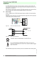
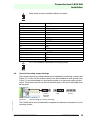
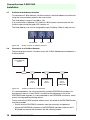
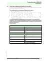
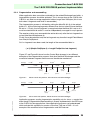
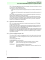
1
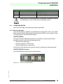
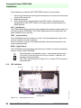
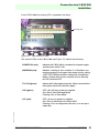
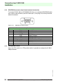
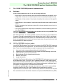
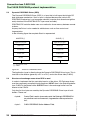
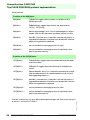
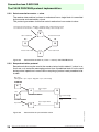
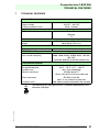
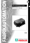
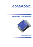
FACTORY AUTOMATION Instruction Manual connection box C-Box 300 With regard to the supply of products, the current issue of the following document is applicable: The General Terms of Delivery for Products and Services of the Electrical Industry, published by the Central Association of the Electrical Industry (Zentralverband Elektrotechnik und Elektroindustrie (ZVEI) e.V.) in its most recent version as well as the supplementary clause: "Expanded reservation of proprietorship" We at Pepperl+Fuchs/VISOLUX recognize a duty to make a contribution to the future. For this reason, this printed matter is produced on paper bleached without the use of chlorine. Date od issue 07/25/2003 Connection box C-BOX 300 Contents 1 Safety precautions . . . . . . . . . . . . . . . . . . . . . . . . . . . . . . . . . . 5 1.1 Power supply . . . . . . . . . . . . . . . . . . . . . . . . . . . . . . . . . . . . . . . . . . . . . 5 1.2 Safety notes . . . . . . . . . . . . . . . . . . . . . . . . . . . . . . . . . . . . . . . . . . . . . . 5 2 General View . . . . . . . . . . . . . . . . . . . . . . . . . . . . . . . . . . . . . . . 7 3 General features . . . . . . . . . . . . . . . . . . . . . . . . . . . . . . . . . . . 10 3.1 Description . . . . . . . . . . . . . . . . . . . . . . . . . . . . . . . . . . . . . . . . . . . . . . 10 4 Installation. . . . . . . . . . . . . . . . . . . . . . . . . . . . . . . . . . . . . . . . 11 4.1 Package contents . . . . . . . . . . . . . . . . . . . . . . . . . . . . . . . . . . . . . . . . . 11 4.2 Opening the device. . . . . . . . . . . . . . . . . . . . . . . . . . . . . . . . . . . . . . . . 11 4.3 Mechanical installation . . . . . . . . . . . . . . . . . . . . . . . . . . . . . . . . . . . . . 12 4.4 Electrical connections and setup . . . . . . . . . . . . . . . . . . . . . . . . . . . . . 13 4.5 Power Supply . . . . . . . . . . . . . . . . . . . . . . . . . . . . . . . . . . . . . . . . . . . . 14 4.6 Chassis Grounding Jumper Settings . . . . . . . . . . . . . . . . . . . . . . . . . . 15 4.7 Profibus Node Address Selection . . . . . . . . . . . . . . . . . . . . . . . . . . . . . 16 4.8 Connection to a Profibus Network . . . . . . . . . . . . . . . . . . . . . . . . . . . . 16 4.9 C-BOX 300 Configuration for Profibus DP Slave Node . . . . . . . . . . . . 17 4.10 4.10.1 4.10.2 Configuration switch and 9-pin internal connector . . . . . . . . . . . . . . . . 18 Switch position "NORMAL OPERATION" (default): . . . . . . . . . . . . . . 18 Switch position "CONFIGURATION": . . . . . . . . . . . . . . . . . . . . . . . . . . 18 4.11 4.11.1 OPERATING MODES . . . . . . . . . . . . . . . . . . . . . . . . . . . . . . . . . . . . . 19 Normal Operation: . . . . . . . . . . . . . . . . . . . . . . . . . . . . . . . . . . . . . . . . 19 4.12 LED Indicators . . . . . . . . . . . . . . . . . . . . . . . . . . . . . . . . . . . . . . . . . . . 20 4.13 PROFIBUS connector (9-pin female external connector) . . . . . . . . . . . 22 4.14 Configuration (CFG): . . . . . . . . . . . . . . . . . . . . . . . . . . . . . . . . . . . . . . 22 5 The C-BOX PROFIBUS protocol implementation . . . . . . . . 23 5.1 Definitions . . . . . . . . . . . . . . . . . . . . . . . . . . . . . . . . . . . . . . . . . . . . . . . 23 5.2 C-BOX's PROFIBUS functional modes . . . . . . . . . . . . . . . . . . . . . . . . 23 5.3 Dynamic PROFIBUS Driver (DPD) . . . . . . . . . . . . . . . . . . . . . . . . . . . . 24 5.4 Structure of exchange areas when DPD is used . . . . . . . . . . . . . . . . . 24 5.5 5.5.1 5.5.2 5.5.3 Control field . . . . . . . . . . . . . . . . . . . . . . . . . . . . . . . . . . . . . . . . . . . . . 25 Data transmission slave --> master . . . . . . . . . . . . . . . . . . . . . . . . . . . 27 Data transmission master --> slave . . . . . . . . . . . . . . . . . . . . . . . . . . . 28 Resynchronization protocol . . . . . . . . . . . . . . . . . . . . . . . . . . . . . . . . . 28 Subject to reasonable modifications due to technical advances. Copyright Pepperl+Fuchs, Printed in Germany Pepperl+Fuchs Group • Tel.: Germany (06 21) 7 76-0 • USA (330) 4 25 35 55 • Singapore 7 79 90 91 • Internet http://www.pepperl-fuchs.com 3 Passive connection box C-BOX 100 General information 5.5.4 Fragmentation and reassembling. . . . . . . . . . . . . . . . . . . . . . . . . . . . . 29 5.6 C-BOX PROFIBUS station address field . . . . . . . . . . . . . . . . . . . . . . . 30 5.7 SAP field . . . . . . . . . . . . . . . . . . . . . . . . . . . . . . . . . . . . . . . . . . . . . . . 30 5.8 Length field. . . . . . . . . . . . . . . . . . . . . . . . . . . . . . . . . . . . . . . . . . . . . . 30 5.9 Application data buffer . . . . . . . . . . . . . . . . . . . . . . . . . . . . . . . . . . . . . 30 5.10 DPD internal queues . . . . . . . . . . . . . . . . . . . . . . . . . . . . . . . . . . . . . . 30 5.11 Application data area with SAP = 0 . . . . . . . . . . . . . . . . . . . . . . . . . . . 31 5.12 Services available with SAP = 255. . . . . . . . . . . . . . . . . . . . . . . . . . . . 31 6 C-BOX data collection using minimum flow control . . . . . . 32 6.1 Definitions . . . . . . . . . . . . . . . . . . . . . . . . . . . . . . . . . . . . . . . . . . . . . . 32 6.2 What to Implement . . . . . . . . . . . . . . . . . . . . . . . . . . . . . . . . . . . . . . . . 33 6.3 Example of exchanges . . . . . . . . . . . . . . . . . . . . . . . . . . . . . . . . . . . . . 33 7 TECHNICAL FEATURES . . . . . . . . . . . . . . . . . . . . . . . . . . . . . 37 General Information This symbol warns the user of possible danger. Failure to heed this warning can lead to personal injury or death and/or damage to equipment This symbol warns the user of possible failure. Failure to heed this warning can lead to total failure of the equipment or any other connected equipment. This symbol gives the user important hints ISO9001 4 Subject to reasonable modifications due to technical advances. Copyright Pepperl+Fuchs, Printed in Germany Pepperl+Fuchs Group • Tel.: Germany (06 21) 7 76-0 • USA (330) 4 25 35 55 • Singapore 7 79 90 91 • Internet http://www.pepperl-fuchs.com Date od issue 07/25/2003 The Pepperl+Fuchs GmbH in D-68301 Mannheim possesses a certified quality assurance system in accordance with ISO 9001. Connection box C-BOX 300 Safety precautions 1 Safety precautions 1.1 Power supply Read this information before installing the product • This product is intended to be installed by Qualified Personnel only. The C-BOX 300 is intended to be supplied either by a UL Listed NEC Class 2 power source, or a UL Listed ITE Limited Power Source (LPS), rated 10 ... 30 VDC, minimum 0.5 A. 1.2 Safety notes Observe the general rules for PROFIBUS components when planning the C-BOX installation. Please observe the following to avoid risk to personnel and damage to equipment and to ensure that the C-BOX 300 operates correctly: Safety regulations Observe the guidelines in the VDE 0100 regulations for handling electrical components, Observe the applicable safety and accident prevention regulations. The C-BOX must only be installed or uninstalled by qualified technical personnel with appropriate electrotechnical qualifications. Observe the guidelines in the PROFIBUS standard EN 50 170. Bus cable Bus wiring should only take place using special shielded, twisted pair PROFIBUS cable. The high data transfer rates can only be guaranteed with the correct cable type. Cable lengths Refer to the manual for the DP master for information on maximum cable lengths for PROFIBUS. Terminating resistors Terminating resistors must be used if the C-BOX is installed at the beginning or end of the PROFIBUS cable segment. In this case, it is recommended to use PROFIBUS connectors which contain an integrated terminating resistor. If the bus is incorrectly terminated, this can lead to errors in data transfer or to damage to other stations on the bus. Date od issue 08/15/2003 PROFIBUS standard Subject to reasonable modifications due to technical advances. Copyright Pepperl+Fuchs, Printed in Germany Pepperl+Fuchs Group • Tel.: Germany (06 21) 7 76-0 • USA (330) 4 25 35 55 • Singapore 7 79 90 91 • Internet http://www.pepperl-fuchs.com 5 Connection box C-BOX 300 Safety precautions Bus connectors It is recommended to use only commercially available PROFIBUS connectors for connecting the bus. Cable shield Shielded cables are less sensitive to interference due to electromagnetic fields. With shielded cables, the interference currents are led to ground through the shielding rail, which is electrically connected to the case. To ensure that the interference currents which flow through the shielding do not themselves interfere with other devices, it is important to provide a low impedance connection to the protective ground. Observe the following rules for the shields of the PROFIBUS cable and the serial interface cable: • The braiding of the shielding should have a degree of coverage of more than 80%. • The shielding should include a braided shield and should not consist solely of foil shielding, since the latter can be easily damaged by cable tension and pressure. • To ensure good immunity to interference at high frequencies as well, the shielding of the cable should be attached to the shielding rail at both ends of the cable. Date od issue 08/15/2003 When connecting up the C-BOX 300, it is recommended to observe the guidelines in the VDE 0100 regulations for handling electrical equipment. 6 Subject to reasonable modifications due to technical advances. Copyright Pepperl+Fuchs, Printed in Germany Pepperl+Fuchs Group • Tel.: Germany (06 21) 7 76-0 • USA (330) 4 25 35 55 • Singapore 7 79 90 91 • Internet http://www.pepperl-fuchs.com Connection box C-BOX 300 General View 2 General View 1 4 3 2 1 25-pin scanner connector 2 Cable glands 3 Cover screws (4) 4 PROFIBUS connector C-BOX 300 Date od issue 08/15/2003 Figure 2.1 Subject to reasonable modifications due to technical advances. Copyright Pepperl+Fuchs, Printed in Germany Pepperl+Fuchs Group • Tel.: Germany (06 21) 7 76-0 • USA (330) 4 25 35 55 • Singapore 7 79 90 91 • Internet http://www.pepperl-fuchs.com 7 Connection box C-BOX 300 General View 2 3 4 5 6 1 7 1 Configuration switch 4 Diagnostic LED 1 2 Power on LED 5 Diagnostic LED 2 3 Tx LED 6 Diagnostic LED 3 7 Node address selector Housing cover inside view Date od issue 08/15/2003 Figure 2.2 8 Subject to reasonable modifications due to technical advances. Copyright Pepperl+Fuchs, Printed in Germany Pepperl+Fuchs Group • Tel.: Germany (06 21) 7 76-0 • USA (330) 4 25 35 55 • Singapore 7 79 90 91 • Internet http://www.pepperl-fuchs.com Connection box C-BOX 300 General View 4 5 6 7 8 3 2 9 1 1 Power on switch 6 SEND button 2 Chassis grounding selector 7 Auxiliary port connector 3 Spring clamp terminal blocks 8 not used 4 GET button 9 Warning LED 5 TEST button Housing base inside view Date od issue 08/15/2003 Figure 2.3 Subject to reasonable modifications due to technical advances. Copyright Pepperl+Fuchs, Printed in Germany Pepperl+Fuchs Group • Tel.: Germany (06 21) 7 76-0 • USA (330) 4 25 35 55 • Singapore 7 79 90 91 • Internet http://www.pepperl-fuchs.com 9 Connection box C-BOX 300 General features 3 General features 3.1 Description The C-BOX 300 is a connection box without display. It can be used as an accessory of the P+F Scanners to perform the following functions: • Facilitate the connection of the scanner signals using a spring clamp connector. • Perform a conversion from RS232 to Profibus to connect a RS232 scanner to a Profibus network. • Get the scanner configuration and store it in memory. • Force the scanner to the Test operating mode. • Send the configuration stored in memory to the scanner. Electrical connection is provided through spring clamp terminal blocks inside the C-BOX 300. The scanner is connected to the C-BOX 300 through a 25-pin female connector placed on the left side of the housing. A 9-pin connector placed inside the C-BOX 300 facilitates connection between an external PC and the auxiliary serial interface of the scanner. Date od issue 08/15/2003 The external 9-pin female connector is used to connect the C-BOX 300 to a Profibus network. 10 Subject to reasonable modifications due to technical advances. Copyright Pepperl+Fuchs, Printed in Germany Pepperl+Fuchs Group • Tel.: Germany (06 21) 7 76-0 • USA (330) 4 25 35 55 • Singapore 7 79 90 91 • Internet http://www.pepperl-fuchs.com Connection box C-BOX 300 Installation 4 Installation 4.1 Package contents Verify that the C-BOX 300 and all the parts supplied with the equipment are present and intact when opening the packaging; the list of parts includes: 1. 2. 3. C-BOX 300 2 mounting screws 1 adhesive label A CD-ROM with the required software and drivers comes separately with each delivery 4.2 Opening the device To install the C-BOX 300 or during normal maintenance, it is necessary to open it by unscrewing the four cover screws: The C-BOX 300 must be disconnected from the power supply during this operation. Figure 4.1 The opened C-BOX 300 It is possible to perform the following operations: • Proceed with the cable connections. • Set the Profibus node address selection on the rotary switches. Date od issue 08/15/2003 • Mount the C-BOX 300 to a wall or panel. Subject to reasonable modifications due to technical advances. Copyright Pepperl+Fuchs, Printed in Germany Pepperl+Fuchs Group • Tel.: Germany (06 21) 7 76-0 • USA (330) 4 25 35 55 • Singapore 7 79 90 91 • Internet http://www.pepperl-fuchs.com 11 Connection box C-BOX 300 Installation 4.3 Mechanical installation The diagram below gives the overall dimensions of the C-BOX 300 and may be used for its installation. Figure 4.2 Mechanical dimensions C-BOX 300 can be installed to operate in different positions. The two screw holes inside the housing of the C-BOX 300 are for mechanical fixture (Figure 4.3). 1. 2. 12 Open the C-BOX 300 by unscrewing the 4 cover screws. If necessary, using the two mounting holes inside the device as a pattern, mark the panel with an appropriate object and then drill two holes in the panel. Align the C-BOX 300 and insert two screws and screw them into the panel until tight (see Figure 4.3). Subject to reasonable modifications due to technical advances. Copyright Pepperl+Fuchs, Printed in Germany Pepperl+Fuchs Group • Tel.: Germany (06 21) 7 76-0 • USA (330) 4 25 35 55 • Singapore 7 79 90 91 • Internet http://www.pepperl-fuchs.com Date od issue 08/15/2003 To mount the C-BOX 300: Connection box C-BOX 300 Installation Figure 4.3 4.4 Mounting the C-BOX 300 Electrical connections and setup The following figure shows the typical layout. PROFIBUS Master C-Box 300 Scanner TX DATA EXT TRIG GOOD READ POWER ON System wiring Figure 4.4 System layout Date od issue 08/15/2003 A PC can be connected to the C-BOX 300 (and consequently to the scanner auxiliary interface) through the internal 9-pin connector. This allows monitoring of the data transmitted by the scanner or configuration through the VisoSetup utility (see scanner Installation Manual for more details). The scanner auxiliary interface signals are also available on the internal spring clamp connectors. After making system cabling and switch settings connect the scanner to the 25-pin female connector on the left side of the C-BOX 300 housing. Switch ON the C-BOX 300 power switch (Figure 4.5). By default, after power on, an automatic connection procedure takes place between Subject to reasonable modifications due to technical advances. Copyright Pepperl+Fuchs, Printed in Germany Pepperl+Fuchs Group • Tel.: Germany (06 21) 7 76-0 • USA (330) 4 25 35 55 • Singapore 7 79 90 91 • Internet http://www.pepperl-fuchs.com 13 Connection box C-BOX 300 Installation the C-BOX 300 and the scanner. During this phase, requiring a few seconds, the warning LED is turned ON. Once the procedure had been completed successfully, the warning LED is turned OFF. After sucessful system check, close the C-BOX 300 using the 4 cover screws making sure the rubber seal is fitted correctly between the parts of the housing. 4.5 Power Supply Power is supplied to the C-BOX 300 through the pins provided on the spring clamp connector. The power switch (see Figure 4.5) switches the power supply ON or OFF for both the C-BOX 300 and the connected scanner. S1 ON OFF Figure 4.5 Power switch ON/OFF positions USER INTERFACE C-BOX 1 VS V+ (10 ... 30 V DC) 2 GND GND Figure 4.6 Power supply connections The power supply must be between 10 and 30 VDC only. The C-BOX 300 spring clamp connector pinouts are indicated in the following table. 14 Subject to reasonable modifications due to technical advances. Copyright Pepperl+Fuchs, Printed in Germany Pepperl+Fuchs Group • Tel.: Germany (06 21) 7 76-0 • USA (330) 4 25 35 55 • Singapore 7 79 90 91 • Internet http://www.pepperl-fuchs.com Date od issue 08/15/2003 Pin 1 is also electrically connected to pins 3 and 5, just as pin 2 is electrically connected to pins 4 and 6. This is useful for external trigger/ inputs connections. Connection box C-BOX 300 Installation Refer to the scanner Installation Manual for details. Pin 1, 3, 5 2, 4, 6 7, 8 9 ... 12, 20, 33, 34, 40 21 23 27 28 35 37 39 VB10, VB12, VB14 22, 24 25, 26, 29, 30, 31, 32 36 38 Description VS GND EARTH GROUND Reserved OUT1+ OUT2+ EXT TRIG+ EXT TRIGTXA RXA SGND OUT REF NC RTSA CTSA Pin 7 or 8 should be connected to the earth ground. 4.6 Chassis Grounding Jumper Settings The scanner chassis grounding method can be selected by positioning a jumper (see Figure 4.7). In this way the scanner chassis can be connected to earth ground (only if pins 7 or 8 are connected to a good earth ground) or to the power supply ground signal. The scanner chassis can also be left floating but, in this case, the jumper must be removed. EARTH GROUND (default) Date od issue 08/15/2003 Figure 4.7 GND floating Jumper settings for chassis grounding The C-BOX 300 is now installed which completes the electrical connections for your scanning system. Subject to reasonable modifications due to technical advances. Copyright Pepperl+Fuchs, Printed in Germany Pepperl+Fuchs Group • Tel.: Germany (06 21) 7 76-0 • USA (330) 4 25 35 55 • Singapore 7 79 90 91 • Internet http://www.pepperl-fuchs.com 15 Connection box C-BOX 300 Installation 4.7 Profibus Node Address Selection To interface the C-BOX 300 with a Profibus network, the Node Address should be set using the rotary switches placed in the cover inside. The valid address range is from 000 to 126. If an invalid value is detected (127-199) the C-BOX cannot communicate with the Profibus network and the green LED remains off. The Node Address can also be assigned through VisoSetup. Refer to Help on-Line. HUNDREDS Figure 4.8 4.8 TENS UNITS Rotary switches for address selection Connection to a Profibus Network The following figure shows a Profibus layout with C-BOX 300 devices connected to a Profibus Master: PROFIBUS DP Master PROFIBUS DP Slave node #1 Figure 4.9 PROFIBUS DP Slave node #2 PROFIBUS DP Slave node #n C-Box 300 Profibus connection of C-BOX 300 To ensure that the C-BOX operates without errors, the shield of the PROFIBUS cable must be grounded. • Ensure that the PROFIBUS connector uses the correct pin assignments. • Attach the PROFIBUS connector to the PROFIBUS interface socket on the CBOX 300 and secure the connector with the retaining screws. 16 Subject to reasonable modifications due to technical advances. Copyright Pepperl+Fuchs, Printed in Germany Pepperl+Fuchs Group • Tel.: Germany (06 21) 7 76-0 • USA (330) 4 25 35 55 • Singapore 7 79 90 91 • Internet http://www.pepperl-fuchs.com Date od issue 08/15/2003 It is recommended to use only commercially available PROFIBUS connectors for connecting to the bus. If the C-BOX is installed at the beginning or end of the PROFIBUS cable segment, it is recommended to use PROFIBUS connectors, which contain an integrated terminating resistor. Connection box C-BOX 300 Installation 4.9 C-BOX 300 Configuration for Profibus DP Slave Node In order to setup the C-BOX 300, you need to install the function blocks in your PLC programming software and configure it. The procedure below can be generally applied for this purpose: 1. 2. 3. 4. Start the PROFIBUS configurator on the DP Master. The .GSD-file is extracted automatically with the installation of the VisoSetup software. It can be found under ...\Visosetup\CBox3x0. Load the .GSD file HMS_1810.GSD in the configurator. Configure the C-BOX 300 (through VisoSetup) setting the parameters according to the PROFIBUS network application as described in the configurator's Help On-Line or User's Manual. For standard applications please choose „Universalmodul“ in your PROFIBUSconfigurator. The I/O-area must be defined in the same way, done with the VisoSetupsoftware (for example 32 byte output, 8 byte input). It’s necessary to choose the whole data-area as consistent. I/O-area of PLC: Input Byte 0 Byte 1 Byte 2 Byte 3 starting Byte 4 Output Byte 0 Byte 1 Byte 2 Byte 3 state byte (has to be toggled at every new action) Profibus adress C-Box 300 always 0 real length of user data (incl. LF, CR, start, stop) user data (for example <STX> or <ETX> as start/stop for softwaretrigger) Date od issue 08/15/2003 starting Byte 4 state byte (toggling at every new action) Profibus adress C-Box 300 Service Access Point real length of user data (incl. LF, CR, start, stop) user data Subject to reasonable modifications due to technical advances. Copyright Pepperl+Fuchs, Printed in Germany Pepperl+Fuchs Group • Tel.: Germany (06 21) 7 76-0 • USA (330) 4 25 35 55 • Singapore 7 79 90 91 • Internet http://www.pepperl-fuchs.com 17 Connection box C-BOX 300 Installation 4.10 Configuration switch and 9-pin internal connector The 9-pin internal connector may have two different functions according to the position of the configuration switch. Figure 4.10 Configuration switch 9-pin male connector 4.10.1 Switch position "NORMAL OPERATION" (default): In this position, the C-BOX 300 is in the normal operating mode. It communicates with the scanner through the 9-pin internal connector and the scanner auxiliary serial interface. The internal connector pinout is illustrated in the following table: Pin Name 1 2 RXA 3 TXA 4 5 SGND 6 9 VB10, VB12, VB14 7 CTSA 8 RTSA 9-pin connector pinout Description N.C. Auxiliary RS232 Auxiliary RS232 N.C. Signal Ground N.C. N.C. Auxiliary Handshake RS232 Auxiliary Handshake RS232 When the switch is in this position, the C-BOX 300 is in configuration mode. The communication with the scanner is interrupted and pins 2 and 3 are no longer dedicated to the scanner auxiliary interface but to the C-BOX 300 configuration (see table below). The system enters configuration mode and waits to be configured through VisoSetup. Once the C-BOX 300 configuration is completed, it is necessary to replace the switch in the Normal Operation position. At the end of the reboot phase, the C-BOX 300 is ready to operate with the new configuration. 18 Subject to reasonable modifications due to technical advances. Copyright Pepperl+Fuchs, Printed in Germany Pepperl+Fuchs Group • Tel.: Germany (06 21) 7 76-0 • USA (330) 4 25 35 55 • Singapore 7 79 90 91 • Internet http://www.pepperl-fuchs.com Date od issue 08/15/2003 4.10.2 Switch position "CONFIGURATION": Connection box C-BOX 300 Installation Pin 2 3 5 Name RX TX SGND 9-pin connector pinout Description C-BOX 300 Configuration C-BOX 300 Configuration Signal Ground When the C-BOX 300 configuration is completed, remember to replace the Configuration switch in the Normal Operation position. 4.11 OPERATING MODES With the C-BOX 300, three operating modes are possible: 4.11.3 Normal Operation: Once the connection procedure is completed (the warning LED is OFF), the C-BOX 300 is ready to receive code strings from the scanners RS 232 main interface. Then, it converts them to the Profibus DP network. GET/TEST/SEND: Through the C-BOX 300 internal buttons it is possible to communicate with the scanner to perform one of the following operations: • Get scanner configuration • Force the scanner in TEST mode • Send a configuration to the scanner At the end of each operation the scanner returns to the previous operating mode. GET/TEST/SEND Functions The C-BOX 300 has three internal function buttons. Buttons GET/TEST/SEND Date od issue 08/15/2003 Figure 4.11 Subject to reasonable modifications due to technical advances. Copyright Pepperl+Fuchs, Printed in Germany Pepperl+Fuchs Group • Tel.: Germany (06 21) 7 76-0 • USA (330) 4 25 35 55 • Singapore 7 79 90 91 • Internet http://www.pepperl-fuchs.com 19 Connection box C-BOX 300 Installation The procedure to enable the GET/TEST/SEND function is the following: 1. 2. 3. Press both the buttons left and right simultaneously for at least one second; the warning LED turnes ON. Release the buttons. Press the left button corresponding to the GET function, the center button corresponding to the TEST function or the right button corresponding to the SEND function. GET – (left button): The C-BOX 300 reads the current scanner configuration and permanently copies it in its internal memory (EEPROM). The C-BOX 300 preserves this configuration also when switched off (non volatile). TEST - (center button): The C-BOX 300 forces the scanner to run the "Test Operating Mode" (refer to the scanner installation manual for details). Press any button to quit the "Test Operating Mode" and return the scanner to the normal operating mode. SEND - (right button): The C-BOX 300 sends the configuration previously stored in its internal permanent memory to the scanners EEPROM. Once the buttons are released in step 1, a ten-second timeout starts. If no button is pressed within this time (no function is selected), the procedure will be cancelled. The C-Box 300 warning LED (Figure 4.12) is turned OFF at the end of each procedure. LED Indicators Power on Tx LD1 LD2 LD3 Date od issue 08/15/2003 4.12 Warning LED Figure 4.12 20 LED Indicators in cover Subject to reasonable modifications due to technical advances. Copyright Pepperl+Fuchs, Printed in Germany Pepperl+Fuchs Group • Tel.: Germany (06 21) 7 76-0 • USA (330) 4 25 35 55 • Singapore 7 79 90 91 • Internet http://www.pepperl-fuchs.com Connection box C-BOX 300 Installation In the C-BOX 300 the warning LED is repeated in the base. Warning LED Figure 4.13 LED Indicators in base The internal LEDs of the C-BOX 300 (see Figure 17) indicate the following: indicates the C-BOX 300 is connected to the power supply and the power switch is ON. WARNING (red): indicates a warning or error condition. It is ON when a connection procedure is in progress (the system is busy), during a GET/TEST/SEND procedure or during the Configuration Mode. It flashes when an error condition occurs. Normally this LED should be OFF. TX, LD3 (green): indicate the Profibus Network activity. When communication takes place, these LEDs will blink slightly. LD2 (green): OFF = Bus off-line or power not supplied. ON = Bus in Data Exchange Mode. Flashing = Bus in Clear Mode. LD1 (red): OFF = No error or power not supplied. ON = Error in initialisation of Profibus ASIC. Flashing = Error in configuration data and / or in user parameter data. Date od issue 08/15/2003 POWER ON (red): Subject to reasonable modifications due to technical advances. Copyright Pepperl+Fuchs, Printed in Germany Pepperl+Fuchs Group • Tel.: Germany (06 21) 7 76-0 • USA (330) 4 25 35 55 • Singapore 7 79 90 91 • Internet http://www.pepperl-fuchs.com 21 Connection box C-BOX 300 Installation 4.13 PROFIBUS connector (9-pin female external connector) To connect C-BOX 300 as a PROFIBUS DP Slave, use a standard PROFIBUS cable with a 9-pin male connector (see DIN 19245 part 1) and plug it into the 9-pin female external connector. Figure 4.14 PROFIBUS connector pinout 9-pin external female connector pinout Pin Name Description 1 N.C. not connected 2 N.C. not connected 3 B-LINE (RS485+) 4 RTS Ready To Send 5 GND RS485 Bus Reference 6 +5 V (galvanically isolated) RS485 Bus Power Supply 7 N.C. not connected 8 A-Line (RS485-) 9 N.C. not connected 4.14 Configuration (CFG): Date od issue 08/15/2003 When the CFG switch is in CFG position (left) it is possible to configure the C-BOX 300 parameters. 22 Subject to reasonable modifications due to technical advances. Copyright Pepperl+Fuchs, Printed in Germany Pepperl+Fuchs Group • Tel.: Germany (06 21) 7 76-0 • USA (330) 4 25 35 55 • Singapore 7 79 90 91 • Internet http://www.pepperl-fuchs.com Connection box C-BOX 300 The C-BOX PROFIBUS protocol implementation 5 The C-BOX PROFIBUS protocol implementation 5.1 Definitions In the following description we will use the following definitions: • Input field: is the set of master inputs that can be modified by the specific slave • Output field: is the set of master outputs that can be read by the specific slave. • MaxInBytes: is the number of input bytes shared by the master and the specific slave. • MaxOutBytes: is the number of output bytes shared by the master and the specific slave. • IN[ Nin ] represent the input byte number Nin, where numbering starts from 0 to MaxInBytes-1 • OUT[ Nout ] represent the output byte number Nout, where numbering starts from 0 to MaxOutBytes-1 Obviously, MaxInBytes and MaxOutBytes are respectively the configured INPUT and OUTPUT AREA sizes. The Exchange Areas are actually updated and read every 30 ms at the C-BOX side. So when a barcode is generated the worst delivery time from C-BOX to the Master station is about 30 ms plus the intrinsic DP PROFIBUS delay and the Master delay (here we neglect the case in which the internal input queue was previously used, see the paragraph DPD internal queues). 5.2 C-BOX's PROFIBUS functional modes Using PROFIBUS protocol Flow Control, four bytes of the PROFIBUS DP exchange areas are reserved for driver operation. So the information field must begin at the fifth byte. These four overhead bytes are used to implement the following features: 1. 2. 3. 4. 5. 6. flow-control and corresponding buffering in both directions; fragmentation and reassembling of data longer than the exchange area sizes; synchronization of flow control numbers; Service Access Point oriented communication; Address Information; Length Information. Date od issue 07/25/2003 Using No Flow Control, all the bytes of the PROFIBUS DP exchange areas are used by the application layer. The input area is updated whenever a new reading event must be transferred to the Master station. Since flow control is not implemented, the Master station must be fast enough to get all the barcode events, reading the input area before it changes due to a new barcode occurrence. In addition, if application data is longer than input area sizes, data is automatically truncated. Since the No Flow Control Mode does not require any particular implementation at the Master side, in the following sections we will examine only the flow controlled version. This will be referred to as Dynamic PROFIBUS Driver (DPD). Subject to reasonable modifications due to technical advances. Copyright Pepperl+Fuchs, Printed in Germany Pepperl+Fuchs Group • Tel.: Germany (06 21) 7 76-0 • USA (330) 4 25 35 55 • Singapore 7 79 90 91 • Internet http://www.pepperl-fuchs.com 23 Connection box C-BOX 300 The C-BOX PROFIBUS protocol implementation 5.3 Dynamic PROFIBUS Driver (DPD) The Dynamic PROFIBUS Driver (DPD) is a layer that is built upon the intrinsic DP data exchange mechanism. Such a layer is required because the intrinsic DP PROFIBUS mechanism is not message oriented (a service that otherwise might be easily obtained if the PROFIBUS FDL layer were available). PROFIBUS DP could be better seen as a method to share memory between remote stations. Anyway the Driver is also needed to add features such as flow control and fragmentation. In the following figure the complete Stack is represented: MASTER (*) SLAVE (**) Application program Application program DPD Layer DPD Layer Profibus DP Profibus DP Profibus FDL Profibus FDL RS 485 RS 485 (*) generally PC or PLC (**) C-BOX Figure 5.1 Structure of PROFIBUS driver The Application Layer is directly above the Dynamic PROFIBUS Driver Layer. This is true both at the Master (generally a PC or a PLC) and at the Slave side (C-BOX). 5.4 Structure of exchange areas when DPD is used In order to implement the flow controlled version of the driver, DP Exchange Areas must be congruently compiled in both directions. INPUT Area is the Exchange buffer from C-BOX to the Master while OUTPUT Area is the exchange buffer from the Master to the C-BOX. Only the first four bytes are used by the Dynamic PROFIBUS Driver layer in both buffers. These are: 24 Control Field, used to issue and control the Datalogic PROFIBUS Driver primitives such as flowcontrol, fragmentation and resynchronization; • byte 1: C-BOX PROFIBUS Station Address Field; Subject to reasonable modifications due to technical advances. Date od issue 07/25/2003 • byte 0: Copyright Pepperl+Fuchs, Printed in Germany Pepperl+Fuchs Group • Tel.: Germany (06 21) 7 76-0 • USA (330) 4 25 35 55 • Singapore 7 79 90 91 • Internet http://www.pepperl-fuchs.com Connection box C-BOX 300 The C-BOX PROFIBUS protocol implementation • byte 2: Service Access Point Field, used to distinguish among different services but also to provide future expandability. Since this SAP definition is introduced by the Datalogic PROFIBUS Driver, it must not be confused with the PROFIBUS SAP that is defined by the international standard. • byte 3: Length Field, that contains the number of bytes used by the application layer. This number must always be less than or equal to MaxInBytes-4 for the IN[] buffer and less than or equal to MaxOutBytes-4 for the OUT[] buffer. 0 1 2 3 ... ... Application Data Buffer [Length Bytes] Exchange Area Buffer [Max (IN/OUT Bytes] byte 3 = Length Field byte 2 = SAP Field byte 1 = Profibus Station Address Field byte 0 = Control Field Figure 5.2 5.5 Data frame structure Control field The Input field structure reserves IN[0] for handshake purposes: bit 0 and bit 1 are used for this. Bit 6 and 7 are set to 0 in order to specify the messaging protocol number 0 is in use. They cannot be used for other purposes. The Output field structure is symmetrical, and reserves bit 0 and 1 for handshake purposes. Bit 6 and 7 are set to 0 to indicate the messaging protocol number 0 is in use. Bit 2 of the Output buffer is used to request a clear of the synchronization numbers (bit 0 and bit 1 of both Input and Output buffers). This is called a resynchronization request and it is always initiated by the Master Station. The Slave must acknowledge the request, using bit 2 of the Input buffer. Date od issue 07/25/2003 Bit 3 is used to control a fragmentation sequence in both directions. Subject to reasonable modifications due to technical advances. Copyright Pepperl+Fuchs, Printed in Germany Pepperl+Fuchs Group • Tel.: Germany (06 21) 7 76-0 • USA (330) 4 25 35 55 • Singapore 7 79 90 91 • Internet http://www.pepperl-fuchs.com 25 Connection box C-BOX 300 The C-BOX PROFIBUS protocol implementation More precisely: Function of the IN[0] byte: IN[0].bit0 = TxBufferFull, toggles when new data is available on IN[1] .. IN[Nin] input area IN[0].bit1 = RxBufferEmpty, toggles when rx block has been read on OUT[1] .. OUT[ Nout] IN[0].bit2 = Resync Acknowledge, set to 1 as an acknowledge to a resync request. With this bit, the master can detect a slave is on line. IN[0].bit3 = More Bit, it must be set to 1 when this is not the last piece of a fragmentation sequence. It must be set to 0 when this is the last piece of a fragmentation sequence. IN[0].bit4,5 = set to 0,0 when this messaging protocol is used. IN[0].bit6,7 = set to 0,0 when this messaging protocol is used (they correspond to the driver version). OUT[0].bit0 = TxBufferEmpty, toggles when transmitted data block has been read from master. OUT[0].bit1 = RxBufferFull, toggles when new data block is available from master. OUT[0].bit2 = Resync Request, set to 1 for 1 second to resynchronize a slave. After resynchronization, all 4 handshake bits are set to 0 and next toggle brings them to 1. OUT[0].bit3 = More Bit, it must be set to 1 when this is not the last piece of a fragmentation sequence. It must be set to 0 when this is the last piece of a fragmentation sequence. OUT[0].bit4,5 = set to 0,0 when this messaging protocol is used. OUT[0].bit6,7 = set to 0,0 when this messaging protocol is used (they correspond to the driver version). Figure 5.3 shows how it is possible to exchange messages with flow control using bit 0 and bit 1 in the IN/OUT buffers. 26 Subject to reasonable modifications due to technical advances. Copyright Pepperl+Fuchs, Printed in Germany Pepperl+Fuchs Group • Tel.: Germany (06 21) 7 76-0 • USA (330) 4 25 35 55 • Singapore 7 79 90 91 • Internet http://www.pepperl-fuchs.com Date od issue 07/25/2003 Function of the OUT[0] byte: Connection box C-BOX 300 The C-BOX PROFIBUS protocol implementation MASTER Profibus DP 0 tx_buffer_full (bit 0) rx_buffer_empty (bit 1) SLAVE 0 1 1 2 2 IN handshake (byte 0) tx buffer (byte 1 ... NIN) tx data NIN NIN tx_buffer_empty (bit 0) rx_buffer_full (bit 1) 0 0 1 1 2 2 handshake (byte 0) rx buffer (byte 1 ... NOUT) OUT rx data NOUT Figure 5.3 NOUT Message exchange with flow control 5.5.1 Data transmission slave --> master The transmission state machine is shown to understand how a single block is transmitted and received. This protocol guarantees a basic flow control mechanism from slave to master. First bit shown in transition --> IN[0].0 / TX Buffer Full = data written by slave Second bit shown in transition --> OUT[0].0 /TX Buffer Empty = data read by master 0,0 A master read tx buff 1,0 D B slave write tx buff Date od issue 07/25/2003 slave write tx buff 0,1 1,1 master read tx buff C Figure 5.4 State machine for block tx slave --> master with PROFIBUS DP Subject to reasonable modifications due to technical advances. Copyright Pepperl+Fuchs, Printed in Germany Pepperl+Fuchs Group • Tel.: Germany (06 21) 7 76-0 • USA (330) 4 25 35 55 • Singapore 7 79 90 91 • Internet http://www.pepperl-fuchs.com 27 Connection box C-BOX 300 The C-BOX PROFIBUS protocol implementation 5.5.2 Data transmission master --> slave The receive state machine is shown to understand how a single block is transmitted by the master and received by a slave. This protocol guarantees a basic flow control mechanism from master to slave. First bit shown in transition --> OUT[0].1 / RX Buffer Full = data written by master Second bit shown in transition --> IN[0].1 /RX Buffer Empty = data read by slave 0,0 A slave read rx buff master write rx buff 0,1 1,0 D B master write rx buff 1,1 slave read rx buff C Figure 5.5 State machine for block rx ( slave <-- master ) with PROFIBUS DP 5.5.3 Resynchronization protocol Resynchronization may be used at the master startup, both to detect if a slave is on line or not, or to restart the messaging protocol from a predefined state. It is also used during normal operations in case of errors requiring a protocol reset procedure to be started. Bits order: -OUT [0].bit2 = Sync request -IN[0].bit2 = Sync acknowledge STARTUP 0 error Sync request 1,X B UNSYNCRONIZED E Sync acknowledge 1,1 IN[0], IN[1], OUT[0], OUT[1] reset SYNCRONIZED Sync finish ack 0,0 Figure 5.6 28 D Sync request finish 0,1 C Date od issue 07/25/2003 A State machine for syncronization action Subject to reasonable modifications due to technical advances. Copyright Pepperl+Fuchs, Printed in Germany Pepperl+Fuchs Group • Tel.: Germany (06 21) 7 76-0 • USA (330) 4 25 35 55 • Singapore 7 79 90 91 • Internet http://www.pepperl-fuchs.com Connection box C-BOX 300 The C-BOX PROFIBUS protocol implementation 5.5.4 Fragmentation and reassembling When application data cannot be contained into the related Exchange Area buffer, a fragmentation process should be activated. This is always done at the C-BOX side. C-BOX is not able to manage application buffers longer than 256 bytes (this is true both when it fragments and when it reassembles). The fragmentation process is initiated by setting the More Bit (bit 3) of the related buffer to 1. All the following fragments different from the last one still have the More Bit set to 1. Finally, the last fragment is recognized since the More Bit is set to 0. It must be noted that bit 0 and bit 1 must be independently managed for any fragment. The receiver station may reassemble the entire data only after the last fragment has arrived (the More Bit becomes 0). Finally it must be noted that only the last fragment may have the Length Field different from Max(In/Out)Bytes-4. So if n fragments have been used, the length of the reassembled data is: ( n-1)*(Max(In/Out)Bytes-4) + Length Field(of the last fragment) Figure 5.7 and Figure 5.8 show how the Control Byte changes in two different examples of the fragmentation process. Note how the More Bit changes and the correlation between fragment and the normal handshake mechanism. p OUT[0] g 0 x 00 0 x 0a 0 x 00 IN[0] 0 x 08 0 x 02 0 x 02 0 x 00 0 x 02 time piece 1 (first) Figure 5.7 piece 2 ack piece 1 ack piece 2 ack piece 3 Master sends data packets, Slave receives and acknowledges p OUT[0] piece 3 (last) g 0 x 00 0 x 00 0 x 00 IN[0] 0 x 01 0 x 09 0 x 01 0 x 00 0 x 08 0 x 01 time piece 1 (first) Date od issue 07/25/2003 Figure 5.8 ack piece 1 piece 2 ack piece 2 piece 3 (last) ack piece 3 Slave sends data packets, Master receives and acknowledges: Application programs use the fragmentation capability only for slave --> master flow even though Fragmentation/Reassembling is already implemented in the DPD layer at the C-BOX for the opposite flow. New application programs can be developed which activate this capability for master->slave flow. The use of SAP = 2 is an example of the combined use of fragmentation and SAP features. Subject to reasonable modifications due to technical advances. Copyright Pepperl+Fuchs, Printed in Germany Pepperl+Fuchs Group • Tel.: Germany (06 21) 7 76-0 • USA (330) 4 25 35 55 • Singapore 7 79 90 91 • Internet http://www.pepperl-fuchs.com 29 Connection box C-BOX 300 The C-BOX PROFIBUS protocol implementation 5.6 C-BOX PROFIBUS station address field The INPUT and OUTPUT buffers keep the information of the selected PROFIBUS address in this field. 5.7 SAP field SAP (Service Access Point) is an identifier that is used to share the same communication channel between processes of two remote stations. This allows splitting the single PROFIBUS DP service into different services. The SAP is introduced by Datalogic and it must not be confused with analogous definitions introduced by PROFIBUS itself. Datalogic has defined the following values: • SAP = 0 is actually used by the slave to transfer acquisition information; it should also be used to transfer application data from Master to Slave (but this is possible only after agreement between the application programs) • SAP = 2 host mode programming. • SAP = 255 for Driver Management Only SAP 255 and 2 are reserved for DPD management. All other SAPs are free and may be used by new application programs after agreement between the application programs themselves. 5.8 Length field The Application layer uses all or a part of the remaining bytes of the Exchange Area buffers that are not used by the Datalogic PROFIBUS Driver. The Length Field is introduced to keep the information of how many bytes are really used by the Application Layer. A fragment that is not the last one of a fragmentation sequence must fill this field with Max(In/Out)Bytes-4, depending on whether it is an INPUT/ OUTPUT fragment. Otherwise this field is filled with a number that is less than or equal to Max(In/Out)Bytes-4. 5.9 Application data buffer The Application data buffer holds useful information processed by the application program. 5.10 DPD internal queues The input queue is used when a new application event (generally a barcode event) has to be transmitted from the C-BOX before the Master station has generated all the acknowledge handshakes for each previous transmission. The output queue is rarely used at the moment. The implementation of new SAPs (i.e. 30 Subject to reasonable modifications due to technical advances. Copyright Pepperl+Fuchs, Printed in Germany Pepperl+Fuchs Group • Tel.: Germany (06 21) 7 76-0 • USA (330) 4 25 35 55 • Singapore 7 79 90 91 • Internet http://www.pepperl-fuchs.com Date od issue 07/25/2003 C-BOX has two internal queues (one for each direction) to keep the application events: input queue and output queue. Connection box C-BOX 300 The C-BOX PROFIBUS protocol implementation SAP=2) will permit application events to be queued in the opposite direction, waiting for use by the C-BOX application layer. The queues are sized in the following way: • X elements of 32 bytes each for input queue (flow from C-BOX to the Master station); • Y elements of 32 bytes each for output queue (flow from the Master station to CBOX). The number of 32-byte elements X and Y are application dependent. Contact your Pepperl+Fuchs distributor for further information. The queues may be flushed by the Master station through the SAP=255 primitive. This is generally done at the Master startup if the Master station wants to cancel all the previous buffers that were generated before its startup. However, the Master station is free to decide not to cancel them. 5.11 Application data area with SAP = 0 SAP = 0 is at the moment used only to transfer barcode events from C-BOX 300 towards the Master station. In IN[4] we can find the first significant byte of the application buffer (the same first byte we would have seen if C-BOX 300 had transmitted the barcode buffer onto a normal serial line instead of the PROFIBUS line). Obviously the structure of the application buffer and its length strictly depends on the selected format on the C-BOX 300. If the length of the application buffer is larger than MaxInBytes-4 the application buffer is split into more pieces through an automatic fragmentation process. 5.12 Services available with SAP = 255 This value of SAP is used for management of the link from the master to the slaves. At the moment only one DPD management service may be issued: the flush of the internal queues. This may be issued anytime. FLUSH QUEUE Service Description: Flush data buffers (issued by the Master station to C-BOX) ACTION: Flush all information from previous decoding phases RESPONSE: Command accepted, Command rejected (generated by C-BOX as response to a previous request from the Master station). Date od issue 07/25/2003 REQUEST: Subject to reasonable modifications due to technical advances. Copyright Pepperl+Fuchs, Printed in Germany Pepperl+Fuchs Group • Tel.: Germany (06 21) 7 76-0 • USA (330) 4 25 35 55 • Singapore 7 79 90 91 • Internet http://www.pepperl-fuchs.com 31 Connection box C-BOX 300 C-BOX data collection using minimum flow control Application data areas are to be formatted as follows: Request Format Command Flush data buffer byte 4 '[' byte 5 'F' Response Format depending on the Retcode Retcode byte 4 byte 5 Command accepted 'A' '' Command rejected 'C' '' All other bytes are insignificantly. 6 C-BOX data collection using minimum flow control Some examples of the Datalogic PROFIBUS Driver (DPD) managing C-BOX are described for the following cases. These are simplified examples using minimum flow control where: • fragmentation/reassembling are not used: the precondition for this is that the input area is large enough (INPUT AREA LENGTH >= barcode string length + 4, see definitions below); 6.1 Definitions • INPUT AREA is one of the two PROFIBUS DP EXCHANGE AREAS. More precisely it is the one that is updated by the C-BOX Slave and read by the Master (generally a PC or a PLC); • OUTPUT AREA is one of the two PROFIBUS DP EXCHANGE AREAS. More precisely it is the one that is updated by the Master and read by the C-BOX Slave station; • INPUT AREA LENGTH length of the input area (must be configured at the Master side with a value greater than or equal to 8); • OUTPUT AREA LENGTH length of the output area (must be configured at the Master side with a value greater than or equal to 8); • Barcode string, all the characters that belong to a barcode event (i.e. the same sequence of characters that would be sent to the asynchronous serial line, if an asynchronous line were used to send barcode data instead of PROFIBUS). This string will be inserted in the input area starting from the fifth byte. 32 Subject to reasonable modifications due to technical advances. Copyright Pepperl+Fuchs, Printed in Germany Pepperl+Fuchs Group • Tel.: Germany (06 21) 7 76-0 • USA (330) 4 25 35 55 • Singapore 7 79 90 91 • Internet http://www.pepperl-fuchs.com Date od issue 07/25/2003 • DPD overhead bytes, these are the first four bytes of both the input and output areas. These bytes are reserved for DPD information. It is composed of: 1. control byte 2. station address byte, it corresponds to the C-BOX station address; 3. SAP byte 4. length byte, in practice it is the significant length of the barcode string; Connection box C-BOX 300 C-BOX data collection using minimum flow control 6.2 What to Implement As a result of the previous definitions we have that: 1. 2. 3. 4. 5. 6. 7. 6.3 C-BOX toggles the first bit of the first byte of the input area whenever a new barcode event is inserted in the input area; this will happen if and only if the previous barcode event had been acknowledged by the Master. If not, data are kept in an internal queue and will be sent only after an explicit acknowledge is received; A Master PLC/PC toggles the first bit of the first byte of the output area in order to acknowledge the reception of the new barcode. The second bytes of both the input and output areas are equal to the PROFIBUS station address of the CBOX; The third bytes of both the input and output areas are equal to SAP (either 0 or 2 in these examples). The fourth byte of the input area is equal to the effective barcode string length inserted in the input area itself. The barcode string is inserted starting from the fifth byte of the input area. All the other bytes of the output area are not relevant. Example of exchanges In the example case we set: • INPUT AREA LENGTH = 16 ; • OUTPUT AREA LENGTH = 8; • PROFIBUS C-BOX station address = 3 Start of DPD exchanges with SAP=0 Before any relative update, the input and output areas are generally full of 0 Input Area 0x00 0x00 0x00 0x00 0x00 0x00 0x00 0x00 0x00 0x00 0x00 0x00 0x00 0x00 0x00 0x00 Output Area 0x00 0x00 0x00 0x00 0x00 0x00 0x00 0x00 Data sent from C-BOX to host Date od issue 07/25/2003 ...... // C-BOX receives a barcode string equal to "0123456" from the scanner // and sends it to Master. Input Area 0x01 0x03 0x00 0x07 0x30 0x31 0x32 0x33 0x34 0x35 0x36 0x00 0x00 0x00 0x00 0x00 Output Area 0x00 0x00 0x00 0x00 0x00 0x00 0x00 0x00 Subject to reasonable modifications due to technical advances. Copyright Pepperl+Fuchs, Printed in Germany Pepperl+Fuchs Group • Tel.: Germany (06 21) 7 76-0 • USA (330) 4 25 35 55 • Singapore 7 79 90 91 • Internet http://www.pepperl-fuchs.com 33 Connection box C-BOX 300 C-BOX data collection using minimum flow control .... // Master receives and acknowledges the barcode event "0123456"; Input Area 0x01 0x03 0x00 0x07 0x30 0x31 0x32 0x33 0x34 0x35 0x36 0x00 0x00 0x00 0x00 0x00 Output Area 0x01 0x03 0x00 0x00 0x00 0x00 0x00 0x00 ..... // C-BOX sends the barcode string equal to "5678" received from the scanner. Input Area 0x00 0x03 0x00 0x04 0x35 0x36 0x37 0x38 0x00 0x00 0x00 0x00 0x00 0x00 0x00 0x00 Output Area 0x01 0x03 0x00 0x00 0x00 0x00 0x00 0x00 .... // Master receives and acknowledges the barcode event "5678"; Input Area 0x00 0x03 0x00 0x04 0x35 0x36 0x37 0x38 0x00 0x00 0x00 0x00 0x00 0x00 0x00 0x00 Output Area 0x00 0x03 0x00 0x00 0x00 0x00 0x00 0x00 ..... // C-BOX sends the barcode string equal to "10DL" received from the scanner. Input Area 0x01 0x03 0x00 0x04 0x31 0x30 0x44 0x52 0x00 0x00 0x00 0x00 0x00 0x00 0x00 0x00 Output Area 0x00 0x03 0x00 0x00 0x00 0x00 0x00 0x00 .... // Master receives and acknowledges the barcode event "10DL"; Input Area 0x01 0x03 0x00 0x04 0x31 0x30 0x44 0x4C 0x00 0x00 0x00 0x00 0x00 0x00 0x00 0x00 Output Area 0x01 0x03 0x00 0x00 0x00 0x00 0x00 0x00 ..... // C-BOX sends the barcode string equal to "P+F" from the scanner. Input Area Output Area 0x01 0x03 0x00 0x00 0x00 0x00 0x00 0x00 .... // Master receives and acknowledges the barcode event "P+F" 34 Subject to reasonable modifications due to technical advances. Copyright Pepperl+Fuchs, Printed in Germany Pepperl+Fuchs Group • Tel.: Germany (06 21) 7 76-0 • USA (330) 4 25 35 55 • Singapore 7 79 90 91 • Internet http://www.pepperl-fuchs.com Date od issue 07/25/2003 0x00 0x03 0x00 0x03 0x44 0x50 0x2B 0x46 0x00 0x00 0x00 Connection box C-BOX 300 C-BOX data collection using minimum flow control Input Area 0x00 0x03 0x00 0x03 0x44 0x50 0x2B 0x46 0x00 0x00 0x00 Output Area 0x00 0x03 0x00 0x00 0x00 0x00 0x00 0x00 Host command sent to C-BOX - C-BOX reply to host request ....(continued from previous exchange) // Master sends a 0x1B 0x02 0x31 0x10 command (as a sample) to the C-BOX. Input Area 0x00 0x03 0x00 0x03 0x44 0x50 0x2B 0x46 0x00 0x00 0x00 Output Area 0x02 0x03 0x00 0x04 0x1B 0x02 0x31 0x10 .... //C-BOX acknowledges the sample command string. Input Area 0x00 0x03 0x00 0x03 0x44 0x50 0x2B 0x46 0x00 0x00 0x00 Output Area 0x02 0x03 0x00 0x04 0x1B 0x02 0x31 0x10 ... // Master sends the Enter Host mode string ESC[C to C-BOX. SAP = 2 Input Area 0x00 0x03 0x00 0x03 0x44 0x50 0x2B 0x46 0x00 0x00 0x00 Output Area 0x00 0x03 0x02 0x03 0x1B 0x5B 0x43 0x00 .... // C-BOX receives, acknowledges and replies to the Enter Host mode string. Input Area 0x01 0x03 0x02 0x04 0x1B 0x48 0x0D 0x0A 0x00 0x00 0x00 0x00 0x00 0x00 0x00 0x00 Output Area 0x00 0x03 0x02 0x03 0x1B 0x5B 0x43 0x00 ... // Master sends the Exit Host mode string ESC[A to C-BOX Input Area 0x01 0x03 0x02 0x04 0x1B 0x48 0x0D 0x0A 0x00 0x00 0x00 0x00 0x00 0x00 0x00 0x00 Date od issue 07/25/2003 Output Area 0x03 0x03 0x02 0x03 0x1B 0x5B 0x41 0x00 .... // C-BOX receives, acknowledges and replies to the Exit Host mode string. Input Area Subject to reasonable modifications due to technical advances. Copyright Pepperl+Fuchs, Printed in Germany Pepperl+Fuchs Group • Tel.: Germany (06 21) 7 76-0 • USA (330) 4 25 35 55 • Singapore 7 79 90 91 • Internet http://www.pepperl-fuchs.com 35 Connection box C-BOX 300 C-BOX data collection using minimum flow control 0x02 0x03 0x02 0x04 0x1B 0x58 0x0D 0x0A 0x00 0x00 0x00 0x00 0x00 0x00 0x00 0x00 Output Area 0x03 0x03 0x02 0x03 0x1B 0x5B 0x41 0x00 .... // Master acknowledges the Exit Host mode string. Input Area 0x02 0x03 0x02 0x04 0x1B 0x58 0x0D 0x0A 0x00 0x00 0x00 0x00 0x00 0x00 0x00 0x00 Output Area 0x02 0x03 0x02 0x03 0x1B 0x5B 0x41 0x00 Host request to C-BOX for resynchronization This example is introduced as a possible solution for monitoring the C-BOX. Resynchronization protocol in this document. The Host requests resynchronization (changes byte [0] bit 2) and monitors the C-BOX response. ...(continued from previous exchange) // Request for Resynchronization by Master //bit 2 to 1 Input Area 0x02 0x03 0x02 0x04 0x1B 0x58 0x0D 0x0A 0x00 0x00 0x00 0x00 0x00 0x00 0x00 0x00 Output Area 0x06 0x03 0x02 0x03 0x1B 0x5B 0x41 0x00 ... // Resynchronization acknowledged by C-BOX //bit 2 to 1; bit 0,1 to 0 Input Area 0x04 0x03 0x02 0x04 0x1B 0x58 0x0D 0x0A 0x00 0x00 0x00 0x00 0x00 0x00 0x00 0x00 Output Area 0x06 0x03 0x02 0x03 0x1B 0x5B 0x41 0x00 ... // End of Resynchronization from Master //bit 2 to 0 Input Area 0x04 0x03 0x02 0x04 0x1B 0x58 0x0D 0x0A 0x00 0x00 0x00 0x00 0x00 0x00 0x00 0x00 Output Area 0x00 0x03 0x02 0x03 0x1B 0x5B 0x41 0x00 ... // End of Resynchronization acknowledged by C-BOX //bit 2 to 0 0x00 0x03 0x02 0x04 0x1B 0x58 0x0D 0x0A 0x00 0x00 0x00 0x00 0x00 0x00 0x00 0x00 Output Area 0x00 0x03 0x02 0x03 0x1B 0x5B 0x41 0x00 36 Subject to reasonable modifications due to technical advances. Copyright Pepperl+Fuchs, Printed in Germany Pepperl+Fuchs Group • Tel.: Germany (06 21) 7 76-0 • USA (330) 4 25 35 55 • Singapore 7 79 90 91 • Internet http://www.pepperl-fuchs.com Date od issue 07/25/2003 Input Area Connection box C-BOX 300 TECHNICAL FEATURES 7 TECHNICAL FEATURES Electrical Features Power Supply voltage Power consumption max. User interface LED indicators Physical features Mechanical dimensions Weight Software features Parameter storage PROFIBUS interface Interface type Data transfer rate [bit/s] Environmental features Operating temperature Storage temperature Humidity max. Vibration resistance Shock resistance Protection class 10 V DC ... 30 V DC 2.9 W + scanner Power ON, Warning, Tx 167 x 115 x 61 mm (6.57 x 4.53 x 2.40 in.) about 440 g. (15.51 oz.) Non-volatile internal memory RS 485 9600, 19200, 93750, 187500, 0.5M, 1.5M, 3M, 6M, 12M, automatic detection of the data transfer rate -10 °C ... 50 °C (14 °F ... 122 °F) -20 °C ... 70 °C (-4 °F ... 158 °F) 90 % (non condensing) IEC 68-2-6 test FC 1.5 mm; 10 to 55 Hz; 2 hours on each axis IEC 68-2-27 test EA 30 G; 11 ms; 3 shocks on each axis IP64 (when correctly connected to the scanner) Date od issue 07/25/2003 The features given are typical at a 25 °C ambient temperature (if not otherwise indicated). Subject to reasonable modifications due to technical advances. Copyright Pepperl+Fuchs, Printed in Germany Pepperl+Fuchs Group • Tel.: Germany (06 21) 7 76-0 • USA (330) 4 25 35 55 • Singapore 7 79 90 91 • Internet http://www.pepperl-fuchs.com 37 Date od issue 07/25/2003 Connection box C-BOX 300 TECHNICAL FEATURES 38 Subject to reasonable modifications due to technical advances. Copyright Pepperl+Fuchs, Printed in Germany Pepperl+Fuchs Group • Tel.: Germany (06 21) 7 76-0 • USA (330) 4 25 35 55 • Singapore 7 79 90 91 • Internet http://www.pepperl-fuchs.com With regard to the supply of products, the current issue of the following document is applicable: The General Terms of Delivery for Products and Services of the Electrical Industry, published by the Central Association of the Electrical Industry (Zentralverband Elektrotechnik und Elektroindustrie (ZVEI) e.V.) in its most recent version as well as the supplementary clause: "Expanded reservation of proprietorship" We at Pepperl+Fuchs/VISOLUX recognize a duty to make a contribution to the future. For this reason, this printed matter is produced on paper bleached without the use of chlorine. gn f d e worl of autom ati on Si s al th or www.pepperl-fuchs.com Worldwide Headquarters Pepperl+Fuchs GmbH · Königsberger Allee 87 68307 Mannheim · Germany Tel. +49 621 776-0 · Fax +49 621 776-1000 e-mail: [email protected] Asia Pacific Headquarters Pepperl+Fuchs Pte Ltd. · P+F Building 18 Ayer Rajah Crescent · Singapore 139942 Tel. +65 67799091 · Fax +65 68731637 e-mail: [email protected] USA Headquarters Pepperl+Fuchs Inc. · 1600 Enterprise Parkway Twinsburg, Ohio 44087 · USA Tel. +1 330 4253555 · Fax +1 330 4254607 e-mail: [email protected] SIGNALS FOR THE WORLD OF AUTOMATION Subject to reasonable modifications due to technical advances Copyright PEPPERL+FUCHS Printed in Germany 129362 07/03 00