1
MT Book #3.qxd
3/19/03
5:02 PM
Page a1
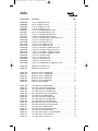
Table of Contents
Introduction
Overview . . . . . . . . . . . . . . . . . . . . . . . . . . . . . . . . . . . . . . . . . . . . . . . . . . . . . . . . . . . . . . . . . . . 1
ALTINEX Technology . . . . . . . . . . . . . . . . . . . . . . . . . . . . . . . . . . . . . . . . . . . . . . . . . . . . . . . . 1
How to Configure a MultiTasker System . . . . . . . . . . . . . . . . . . . . . . . . . . . . . . . . . . . . . . . . . . 2
How to Read an ALTINEX Block Diagram . . . . . . . . . . . . . . . . . . . . . . . . . . . . . . . . . . . . . . . . 4
How to Choose Components in a MultiTasker System . . . . . . . . . . . . . . . . . . . . . . . . . . . . . . . 6
Enclosures
19-Slot Enclosure . . . . . . . . . . . . . . . . . . . . . . . . . . . . . . . . . . . . . . . . . . . . . . . . . . . . . . . . . . . . 8
19-Slot Front Panel Options . . . . . . . . . . . . . . . . . . . . . . . . . . . . . . . . . . . . . . . . . . . . . . . . . . . . 9
8-Slot Enclosure . . . . . . . . . . . . . . . . . . . . . . . . . . . . . . . . . . . . . . . . . . . . . . . . . . . . . . . . . . . . 10
8-Slot Front Panel Options . . . . . . . . . . . . . . . . . . . . . . . . . . . . . . . . . . . . . . . . . . . . . . . . . . . . 11
Video Distribution Amplifiers
Video Distribution Amplifiers . . . . . . . . . . . . . . . . . . . . . . . . . . . . . . . . . . . . . . . . . . . . . . . . .
Video Distribution Amplifier Expansion . . . . . . . . . . . . . . . . . . . . . . . . . . . . . . . . . . . . . . . . .
Video Line Driver/GLI . . . . . . . . . . . . . . . . . . . . . . . . . . . . . . . . . . . . . . . . . . . . . . . . . . . . . . .
S-Video Distribution Amplifiers . . . . . . . . . . . . . . . . . . . . . . . . . . . . . . . . . . . . . . . . . . . . . . . .
Dual Video/S-Video Distribution Amplifiers . . . . . . . . . . . . . . . . . . . . . . . . . . . . . . . . . . . . . .
VGA-Type Distribution Amplifiers . . . . . . . . . . . . . . . . . . . . . . . . . . . . . . . . . . . . . . . . . . . . .
VGA-Type Distribution Amplifier Expansion . . . . . . . . . . . . . . . . . . . . . . . . . . . . . . . . . . . . .
VGA-Type Line Driver/GLI . . . . . . . . . . . . . . . . . . . . . . . . . . . . . . . . . . . . . . . . . . . . . . . . . . .
12
14
16
18
20
22
24
26
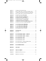
Video Switchers
Video Switchers . . . . . . . . . . . . . . . . . . . . . . . . . . . . . . . . . . . . . . . . . . . . . . . . . . . . . . . . . . . .
Video Switcher Expansion . . . . . . . . . . . . . . . . . . . . . . . . . . . . . . . . . . . . . . . . . . . . . . . . . . . .
S-Video Switcher . . . . . . . . . . . . . . . . . . . . . . . . . . . . . . . . . . . . . . . . . . . . . . . . . . . . . . . . . . .
Dual Video/S-Video Switcher . . . . . . . . . . . . . . . . . . . . . . . . . . . . . . . . . . . . . . . . . . . . . . . . . .
VGA-Type Switchers . . . . . . . . . . . . . . . . . . . . . . . . . . . . . . . . . . . . . . . . . . . . . . . . . . . . . . . .
VGA-Type Switcher Expansion . . . . . . . . . . . . . . . . . . . . . . . . . . . . . . . . . . . . . . . . . . . . . . . .
28
30
32
34
36
38
Video Matrix Switchers
Small Video Matrix Switchers . . . . . . . . . . . . . . . . . . . . . . . . . . . . . . . . . . . . . . . . . . . . . . . . . 40
Mid-Size Video Matrix Switchers . . . . . . . . . . . . . . . . . . . . . . . . . . . . . . . . . . . . . . . . . . . . . . 42
Small VGA-Type Matrix Switchers . . . . . . . . . . . . . . . . . . . . . . . . . . . . . . . . . . . . . . . . . . . . . 44
Special Functions
VGA-Type CAT-5 Transmitter/Receiver . . . . . . . . . . . . . . . . . . . . . . . . . . . . . . . . . . . . . . . . .
Scan Reducer . . . . . . . . . . . . . . . . . . . . . . . . . . . . . . . . . . . . . . . . . . . . . . . . . . . . . . . . . . . . . .
Scan Doubler . . . . . . . . . . . . . . . . . . . . . . . . . . . . . . . . . . . . . . . . . . . . . . . . . . . . . . . . . . . . . . .
Scaler . . . . . . . . . . . . . . . . . . . . . . . . . . . . . . . . . . . . . . . . . . . . . . . . . . . . . . . . . . . . . . . . . . . . .
46
48
50
52
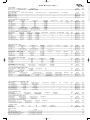
Audio
Stereo Audio Distribution Amplifier — Unbalanced . . . . . . . . . . . . . . . . . . . . . . . . . . . . . . . .
Stereo Audio Distribution Amplier — Balanced . . . . . . . . . . . . . . . . . . . . . . . . . . . . . . . . . . .
Stereo Audio Line Driver + GLI — Unbalanced/Balanced . . . . . . . . . . . . . . . . . . . . . . . . . . .
Stereo Audio Switcher — Unbalanced In . . . . . . . . . . . . . . . . . . . . . . . . . . . . . . . . . . . . . . . .
Stereo Audio Switcher — Balanced In . . . . . . . . . . . . . . . . . . . . . . . . . . . . . . . . . . . . . . . . . .
Audio Matrix Switchers . . . . . . . . . . . . . . . . . . . . . . . . . . . . . . . . . . . . . . . . . . . . . . . . . . . . . .
Audio Power Amplifiers . . . . . . . . . . . . . . . . . . . . . . . . . . . . . . . . . . . . . . . . . . . . . . . . . . . . . .
54
56
58
60
62
64
66
MT Book #3.qxd
3/19/03
5:02 PM
Page a2
Control
Control Cards . . . . . . . . . . . . . . . . . . . . . . . . . . . . . . . . . . . . . . . . . . . . . . . . . . . . . . . . . . . . . . 68
Accessories
Patch Cables . . . . . . . . . . . . . . . . . . . . . . . . . . . . . . . . . . . . . . . . . . . . . . . . . . . . . . . . . . . . . . . 70
Sample Configurations
Sample Configuration #1
Sample Configuration #2
Sample Configuration #3
Sample Configuration #4
Sample Configuration #5
Sample Configuration #6
Sample Configuration #7
.....................................................
.....................................................
.....................................................
.....................................................
.....................................................
.....................................................
.....................................................
72
74
76
78
80
82
84
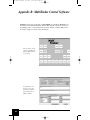
Appendix A: Controlling a MultiTasker System . . . . . . . . . . . . . . . . . . . . . . . . . . . . . . . . . . . 86
Appendix B: MultiTasker Control Software . . . . . . . . . . . . . . . . . . . . . . . . . . . . . . . . . . . . . . 90
ALTINEX, Signal Management Solutions, and MultiTasker are registered trademarks of ALTINEX, Inc. Windows, Windows
95, Windows 98, Windows NT, Windows 2000, and Windows XP are registered trademarks of Microsoft Corporation. All
other registered trademarks and trademarks are the property of their respective companies.
While ALTINEX, Inc. believes the information contained herein to be accurate and current as of publication, it makes no warranty of any kind, expressed or implied. ALTINEX, Inc. assumes no liability or obligation of any kind, and the reader is cautioned to abide by all national and local codes, rules, and regulations, and to use common sense in utilizing this information.
Information in this catalog is subject to change at any time without notice.
© 2002 ALTINEX, Inc. All rights reserved.
MT Book #3.qxd
3/19/03
5:02 PM
Page 1
MultiTasker Design Guide
®
The ALTINEX MultiTasker is the new, modular system for customizing signal management
solutions for a variety of audio, video, and control signals. With MultiTasker, you can accomplish
distribution, switching, matrix switching, and signal conversion in one comprehensive rack-based
system. And, as a modular system, you can change the configuration and re-program functionality with a minimum of component change.
This Design Guide will provide you with a comprehensive overview of the MultiTasker system
— how it works, what options are available, and how to design a MultiTasker-based signal management system to meet your audio-visual requirements. It is organized into four basic sections
— an Introduction, Product Information, Sample Configurations, and a Quick Reference guide.
Introduction
The introduction provides a quick tutorial on the conventions used throughout the guide, as well
as a procedural guide to designing a MultiTasker System. It explains the symbols used in each
product’s block diagram, and describes the various function groupings of MultiTasker cards to
help you identify the right ones for your signal management system.
Product Information
In the Product Information section, the products have been grouped according to the functionality
that they share, with the differences in specific features listed in the initial product comparison at
the head of each product group page. A line drawing of the front panel follows, alongside a representative photo, which illustrates the input and output connector placement. On the facing page
are the functional block diagrams for each card. These diagrams illustrate the signal flow through
the card, and define such options as expandability, switching, and special options such as on/off
control or signal detect. The Design Tips part of each product group will mention design requirements and dependencies, suggest alternative usages for extending the functionality of the products in that group, and list important accessories for full utilization of those products.
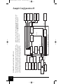
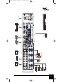
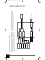
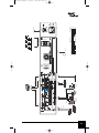
Sample Configurations
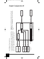
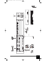
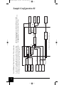
Sample Configurations show how various signal management challenges can be efficiently, effectively, and comprehensively met with a MultiTasker solution. Each one starts by defining input
and output requirements using signal block diagrams. The components necessary to achieve the
desired objectives are then chosen and shown in the assembled MultiTasker configuration.
Quick Reference
The Quick Reference fold-out chart provides a single-page view of all the MultiTasker products
profiled in this guide, and allows side-by-side comparison of their distinguishing specifications.
ALTINEX Technology
ALTINEX is at the forefront of developing new technologies to solve the more persistent challenges in signal distribution. Following are some terms you will encounter frequently in this guide:
• GLI on-board was developed to eliminate ground loops, thereby removing the symptoms of
TM
rolling hum bars and other artifacts in video signals, and hum in unbalanced audio.
• Screen Blanking prevents the annoying “No Signal Present” message from appearing on displays while allowing the user to turn off, or “blank” the actual computer signal.
• Sync Delay promotes graceful switching between computer video signal sources, without the
visual “glitch” that commonly occurs during the transition from one source to another.
ALTINEX, Inc. • Toll Free: 800-ALTINEX • Tel: 714-990-2300 • Fax: 714-990-3303 • Web: www.altinex.com
MT Book #3.qxd
3/19/03
5:02 PM
Page 2
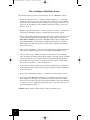
How to Configure a MultiTasker System
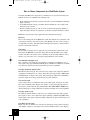
The following design steps provide a basic methodology to create a MultiTasker solution:
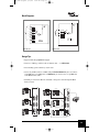
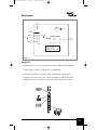
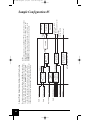
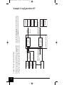
1. Identify all of the signal sources — computers, cameras, microphones, etc.— their signal
formats and connector types. If there are computer sources, make note of what resolutions
and refresh rates they will be used at. In the example on the facing page, note that the computer source has been defined to deliver an XGA resolution video signal, as well as stereo
audio (see Figure 1).
2. Identify all of the signal destinations — monitors, projectors, or recorders — and make note
of their signal compatibility, connectors, resolutions and refresh rates they support.
3. Choose a video format standard. Just as broadcast video can be routed in composite, S-Video
or component signal formats (Y, Pr, Pb/Y, R-Y, B-Y), computer video can be routed as
RGsB, RGBS or RGBHV analog formats or DVI digital formats. Choose standards reflecting the minimal number of format changes, and with which the displays are compatible.
With computer video, make sure that the sync signal format is compatible with all display
and conversion devices.
4. Verify scan rate compatibility — make sure that the output devices can display the input signals, or that the appropriate signal converter is specified into the MultiTasker system.
5. Choose a connector type to minimize the number of conversions necessary, and thereby
reduce the potential for signal degradation. In the example on the facing page the 15-pin HD
connector type from the source computer output is maintained throughout the signal flow
diagram. The audio signal, however, is converted from 3.5mm connector output to RCA
jacks, for better connectivity to a variety of output devices.
6. Create a signal flow diagram, noting any special features required from each component of
the block diagram. In the example on the facing page, all signals are defined and identified
by type and connector.
7. Select a control method and user interface — push-button, controller, computer, or none.
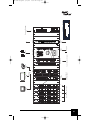
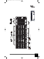
8. Select the appropriate MultiTasker components to accomplish the required signal routing.
In the example on the facing page, the signal function, resolution and connector requirements were used to pick the appropriate cards from the VGA DA card group and Audio DA
card group (see Figure 2). Finally, the eight-slot enclosure was chosen as the best size to fit
the system requirements (Figure 3).
ALTINEX technical support is available to help you with any step in this process.
2
ALTINEX, Inc. • Toll Free: 800-ALTINEX • Tel: 714-990-2300 • Fax: 714-990-3303 • Web: www.altinex.com
MT Book #3.qxd
3/19/03
5:02 PM
Page 3
®
HD15
1x6DA
Figure 1
System flow diagram
XGA
Monitor
HD15
HD15
1x6DA
XGA
Monitor
RCA
HD15
HD15
XGA
XGA
Computer
Amplified
Speaker
System
RCA
3.5mm
Stereo
Audio
Stereo Audio
1x6DA
Enclosure + Front Panel
MT103-103
MT103-104
MT108-100
INPUT
RED POWER/
GREEN SIGNAL PRESENT
INPUT
OUTPUT
1
OUTPUT
R
L
R
L
R
L
R
L
R
L
R
L
Figure 2
MultiTasker cards
103-103, 103-104,
and 108-100
2
4
1
4
1
3
4
5
2
5
2
5
6
3
6
OUTPUT
3
AUDIO DA
Figure 3
MultiTasker cards (above), front panel (right),
and 8-slot enclosure
TM
RS-232
MT108-100
RED POWER/
GREEN SIGNAL PRESENT
R
R
R
R
R
OUTPUT
R
AUDIO DA
INPUT
OUTPUT
4
5
6
MT103-103
INPUT
1
2
3
4
5
6
MultiTasker
TM
Pins
2-Tx
3-Rx
5-GND
RS-232
L
L
L
L
L
L
MT100-101
1
2
3
4
2
1
MT103-104
5
3
OUTPUT
6
100-240V~ 2.5A
6
ALTINEX, Inc. • Toll Free: 800-ALTINEX • Tel: 714-990-2300 • Fax: 714-990-3303 • Web: www.altinex.com
!
3
MT Book #3.qxd
3/19/03
5:02 PM
Page 4
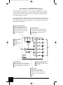
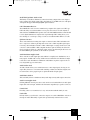
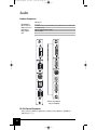
How To Read an ALTINEX Block Diagram
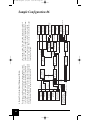
This Design Guide uses block diagrams to describe the functions of MultiTasker cards. These
diagrams provide useful insight into the connections available, and flow of the signal through
each individual product. In the following section, the various symbols used in these block diagrams will be identified and explained.
By following the signal lines from the inputs to the outputs, block diagrams can be used to determine the number and type of cards and connections needed to complete your configuration. Additional card functionality is also listed here. Opposite is a list of symbols describing components
and features inside each diagram.
Internal Connection Feature
This part of the diagram indicates if a
card can be expanded, or connected
to other cards internally. This example
shows the ability to connect up to four
additional cards internally.
EXP 1
EXP 2
Internal Components
This example shows the outputs as buffered
and switched. Each “triangle” is an amplifier,
and the broken line terminated by a circle
represents a switch.
EXP 3
EXP 4
OUTPUT 1
Number and Type
of Inputs
This example shows
a BNC connector on
the input.
OUTPUT 2
OUT PUT 3
BNC
INPUT
BNC
GLI
OUTPUT 4
SIGNAL
DETECT
OUTPUT
ON/OFF
CONTROL
Special Functions
Software-activated features are indicated in
”function boxes” like this one. This example
shows the capability to turn outputs on or off.
POWER
OUTPUT 5
OUTPUT 6
Number and Type of Outputs
This example shows BNC connectors
on the output.
Indicator Light
If an LED is present on the card, then
it is shown here, with the functions
indicated on either side. This LED performs
two functions — indicating signal detect
and power.
4
ALTINEX, Inc. • Toll Free: 800-ALTINEX • Tel: 714-990-2300 • Fax: 714-990-3303 • Web: www.altinex.com
MT Book #3.qxd
3/19/03
5:02 PM
Page 5
®
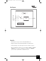
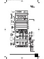
Amplifier
buffers either the input, or output, or both
Jumpers
show where manual signal routing can be performed during installation
GLI
j
PLUG AND PLAY
GLI (Ground Loop Isolation)
protects system against humming and rolling bars in video
Audio Mixer
allows simultaneous output of all inputs, with input level control of each
Plug and Play
Plug and Play circuitry (on 15-pin HD connectors)
On-off Control
requires software commands to enable/disable signal
Switch
switches between multiple signals; chooses one at a time for output
Sliding Switch
usually a hardware switch located on faceplate of card
Contact-NO
contact “normally open” switch
Contact-NC
contact “normally closed” switch
H/W
EQ
S/W
EQ
H/W
GAIN
S/W
GAIN
H/W
HPos
Hardware Equalization
manual control of output video signal through on-board potentiometer
Software Equalization
software control of output video signal through RS-232 or front panel control
Hardware Gain Control
manual control of audio signal gain through on-board potentiometer
Software Gain Control
software control of audio signal gain through RS-232 or front panel control
HPos
potentiometer-based horizontal position control
ALTINEX, Inc. • Toll Free: 800-ALTINEX • Tel: 714-990-2300 • Fax: 714-990-3303 • Web: www.altinex.com
5
MT Book #3.qxd
3/19/03
5:02 PM
Page 6
How to Choose Components in a MultiTasker System
To find the right Multitasker component for each function in your system, the following determinations need to be accomplished in the following order:
1. Decide which basic function that a particular card needs to perform: Distribution? Switching?
Signal conversion?
2. Look within that function group to determine which card handles the correct signal format
and has the proper connector.
3. From the resulting sub-group of cards, choose the one that has the appropriate number of
inputs and outputs, and meets the performance specifications and special functions required.
MultiTasker components have been organized into the following function groups:
Enclosures
These are the starting points in any MultiTasker system. They hold the other components of the
system and provide power and control signals to them. Multiple enclosures can be “ganged” to
accomplish more extensive signal management. Although listed separately, a front panel must
always be ordered with an enclosure.
Front Panels
The front panel is typically chosen to support the level of functionality required by the cards
being used in the MultiTasker system. For simple audio and video distribution, just a simple
faceplate will suffice. For external control of switching, a front panel with an RS-232 control
interface is necessary. There is also a front panel with push-button control available.
Video Distribution Amplifier Cards
These cards take a video signal input and condition it or amplify it for distribution to one or
many outputs. They support different bandwidth signals, and different combinations of distribution, expansion, output on-off control, and ground-loop protection capabilities.
VGA-Type Distribution Amplifier Cards
Much like the Video DA group, these cards take in one computer video signal and condition it
or amplify it for distribution to one or many outputs. They offer support VGA to QXGA-bandwidth distribution of computer video signals, along with varying combinations of distribution,
expansion, output on-off control, and ground-loop protection capabilities.
Video Switcher Cards
A video switcher allows you switch between two or more input signals, choosing one for output.
These cards work directly with composite video, S-Video, or can be ganged in groups of three to
five in order to switch component video (Y, Pb, Pr/Y, R-Y, B-Y), RGsB, RGBS or RGBHV. Also
offered in this group are varying combinations of expansion and output on-off control capabilities.
VGA-Type Switcher Cards
The VGA-type Switcher family of cards allows you to switch between many input computer
video signals to choose one for output. They support switching of VGA through QXGA bandwidth computer video signals, along with varying combinations of expansion and output on-off
control capabilities.
Video Matrix Switcher Cards
Matrix cards allow for simultaneous connections of many inputs to many outputs. Using these
cards, multiple computer or video inputs can be routed to multiple monitors or other displays.
6
ALTINEX, Inc. • Toll Free: 800-ALTINEX • Tel: 714-990-2300 • Fax: 714-990-3303 • Web: www.altinex.com
MT Book #3.qxd
3/19/03
5:02 PM
Page 7
®
Small VGA-Type Matrix Switcher Cards
This family of cards allows simultaneous connection of many computer video source inputs to
many computer video display outputs. They offer VGA-type 15-pin HD connectors on all inputs
and outputs and support VGA through QXGA signal resloutions.
CAT-5 Transmitters/Receivers
These MultiTasker cards are used to transmit analog computer video signals over CAT-5 type
UTP cable. They are used in transmitter-reciever pairs, and can also be used in conjunction
with stand-alone ALTINEX CAT-5 products such as the DA1920SX transmitter or DA1921SX
receiver. Signal distribution of computer video signals through CAT-5 cabling allows you to
take advantage of cost and space savings over the use of traditional multi-channel coax cable.
Up/Down Converters
These cards translate the incoming video signals to alternate formats. The Scan Doubler will
take a composite or S-Video signal input and convert it into a VGA-compatible signal output.
Conversely, the Scan Reducer will take a VGA or XGA signal of varying refresh rates in, and
convert it to either an NTSC or PAL-compatible broadcast signal out. Finally, the Scaler will
take in a broadcast, VGA-type or DVI video signal, switch to the desired input and convert it to
the VGA-UXGA signal you define, at the refresh rate you define.
Audio Distribution Amplifier Cards
These cards take an audio signal input, and condition it or amplify it for distribution to one or
many outputs. Available with a variety of I/O connectors and balanced or unbalanced configurations, these cards offer different combinations of distribution, expansion, output on-off control, and ground-loop protection features.
Audio Switcher Cards
An audio switcher allows you to switch between two or more input signals, choosing one for
output. They allow stereo or monaural audio switching of balanced or unbalanced signals, and
in some instances can be ganged in pairs to expand the number of input signals.
Audio Matrix Switchers
This card family allows for simultaneous many-audio-input to many-audio-output connections.
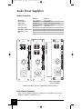
Audio Power Amplifier Cards
Utilizing additional external power, these cards can mix several standard line-level audio signal
inputs with a mic-level input, and deliver the final audio output directly to speakers or line out.
Control Cards
Exercising control over external devices is easy and convenient with this family of cards.
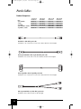
Patch Cables
In many instances you will need to connect the output of one card in a MultiTasker enclosure to
the input of another. This family of patch cables provides handy solutions for those needs.
ALTINEX, Inc. • Toll Free: 800-ALTINEX • Tel: 714-990-2300 • Fax: 714-990-3303 • Web: www.altinex.com
7
MT Book #3.qxd
3/19/03
5:02 PM
Page 8
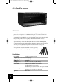
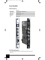
19-Slot Enclosure
MT100-100
The MT100-100 enclosure consists of 19 slots, a power supply, and a backplane to route
power and control signals to the cards. On the back panel of the 19-slot enclosure is an
IEC-320 male power connector, an on-off switch, and a 9-pin D-sub female connector for
external RS-232 control. (RS-232 control is activated only when used in conjunction with a
front panel that provides control capability to the cards installed in the enclosure).
A front panel must be chosen with this enclosure; three are available, each with different
capabilities to complement the functionality of the cards used in the enclosure. Optionally, a
second power supply may be installed, either for redundancy in mission-critical applications
or if more power is required by a large number of scan conversion or scaling cards.
To keep dust out, unused slots should be covered by separately
available slot covers (MT200-105: package of five blank covers).
MT200-105
Specifications
Slots Available
Weight (empty, no slot covers)
Ship Weight (approx.)
MTBF (calc.)
Rack Space (19")
Power Input
Power to Cards
Power Consumption
Approvals
8
19 (20 for custom applications)
15 lb (6.8 kg)
20 lb (9.1 kg)
60,000 hrs
4U high, 1 rack wide, 12" (30.5 cm) deep
100-240 V AC (50/60 Hz), 2.0 A maximum
–13V, –6V, +6V, +13V
45 W maximum per power supply,
90 W with 2 power supplies installed; other options available
20 W minimum/250 W maximum,
depending on power supply options installed
FCC and CE
ALTINEX, Inc. • Toll Free: 800-ALTINEX • Tel: 714-990-2300 • Fax: 714-990-3303 • Web: www.altinex.com
MT Book #3.qxd
3/19/03
5:02 PM
Page 9
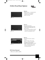
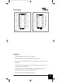
19-Slot Front Panel Options
®
MT101-102
• Blank front panel — no controller included
• Primarily for no-control-required
applications such as distribution
• Includes cooling fans
MT101-102
MT101-100
MT101-101
MT101-100
• Front panel with controller
• Required for applications using external
control, such as switching, which use the
RS-232 interface
• Includes cooling fans, microprocessor-based
control interface, and 9-pin D-sub female
connector for external RS-232 control
MT101-101
• Front panel with controller, 36-button
interface
• Allows front-panel control of cards
• Buttons are completely configurable
through RS-232 control interface
• Includes cooling fans, microprocessor-based
interface, 9-pin D-sub female connector
for RS-232 control/programming, and
36 programmable buttons
RS-232 Control Commands
[RESUi], [CnUi], [VERCnUi], [SETUi]
ALTINEX, Inc. • Toll Free: 800-ALTINEX • Tel: 714-990-2300 • Fax: 714-990-3303 • Web: www.altinex.com
9
MT Book #3.qxd
3/19/03
5:02 PM
Page 10
8-Slot Enclosure
MT100-101
The MT100-101 enclosure consists of 8 slots and a backplane to route power and control signals to the cards. On the back panel of the 8-slot enclosure is an IEC-320 male power connector, an on-off switch, and a 9-pin D-sub female connector for external RS-232 control. (RS-232
control is activated only when used in conjunction with a front panel that provides control capability to the cards installed in the enclosure).
A front panel must be chosen with this enclosure; three are available, each with different
capabilities to complement the functionality of the cards used in the enclosure. Each front
panel includes the power supply for the unit.
To keep dust out, unused slots should be covered by separately
available slot covers (MT200-105: package of five blank covers).
MT200-105
Specifications
Slots Available
Weight (empty, no slot covers)
Ship Weight (approx.)
MTBF (calc.)
Rack Space (19")
Power Input
Power to Cards
Power Consumption
Approvals
10
8
11 lb (5 kg)
15 lb (6.8 kg)
100,000 hrs
2U high, 1 rack wide, 12" (30.5 cm) deep
100-240 V AC (50/60 Hz), 2.0 A maximum
–13V, –6V, +6V, +13V
45 W maximum per power supply,
90 W with 2 power supplies installed
10 W minimum/160 W maximum,
depending on power supply options installed
FCC and CE
ALTINEX, Inc. • Toll Free: 800-ALTINEX • Tel: 714-990-2300 • Fax: 714-990-3303 • Web: www.altinex.com
MT Book #3.qxd
3/19/03
5:02 PM
Page 11
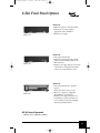
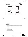
8-Slot Front Panel Options
MT101-103
MT101-104
MT101-105
®
MT101-103
• Blank front panel-no controller included
• Primarily for no-control-required
applications such as distribution
• Includes power supply
MT101-104
• Front panel with controller
• Required for applications using external
control, such as switching, which use the
RS-232 interface
• Includes power supply, microprocessor-based
control interface, and 9-pin D-sub female
connector for external RS-232 control
MT101-105
• Front panel with controller, 36 button
interface
• Allows front-panel control of cards
• Buttons are completely configurable
through RS-232 control interface
• Includes power supply, microprocessorbased interface, 9-pin D-sub female connector for RS-232 control/programming,
and 36 programmable buttons
RS-232 Control Commands
[RESUi], [CnUi], [VERCnUi], [SETUi]
ALTINEX, Inc. • Toll Free: 800-ALTINEX • Tel: 714-990-2300 • Fax: 714-990-3303 • Web: www.altinex.com
11
MT Book #3.qxd
3/19/03
5:03 PM
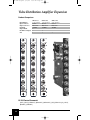
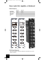
Page 12
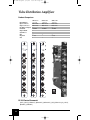
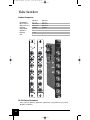
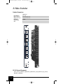
Video Distribution Amplifiers
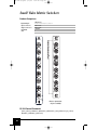
Product Comparison
Inputs/Outputs
Input Connectors
Output Connectors
Ind. Buffered Outputs
Bandwidth
Output On/Off
Signal Detect
GLI
Expansion
Slots
MT103-100
1-in 6-out
BNC female
BNC female
9
350 MHz
9
9
9
4 cards
1
MT103-105
1-in 6-out
BNC female
BNC female
250 MHz
9
1
MT103-105
MT103-100
RED POWER/
GREEN SIGNAL
POWER
POWER
IN
IN
OUT
OUT
OUT
1
1
1
2
2
2
3
3
3
4
4
4
5
5
5
6
VIDEO DA
9
4 cards
1
MT103-111
IN
6
MT103-111
1-in 6-out
BNC female
BNC female
9
350 MHz
6
VIDEO DA
VIDEO DA
RS-232 Control Commands
[CnUi], [GkUi], [VERCnUi], [ONmCnUi], [OFFmCnUi], [SW], [WRCnCoCpCq...GkUi],
[RDGkUi], [CLRGkUi]
12
ALTINEX, Inc. • Toll Free: 800-ALTINEX • Tel: 714-990-2300 • Fax: 714-990-3303 • Web: www.altinex.com
MT Book #3.qxd
3/19/03
5:03 PM
Page 13
®
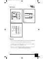
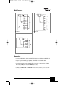
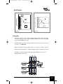
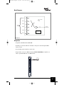
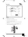
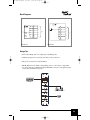
Block Diagrams
EXP 1
EXP 2
EXP 3
EXP 4
OUTPUT 1
POWER
OUTPUT 2
OUTPUT 1
OUTPUT 2
OUTPUT 3
OUTPUT 3
BNC
INPUT
BNC
GLI
INPUT 1
BNC
GLI
BNC
OUTPUT 4
OUTPUT 4
OUTPUT 5
SIGNAL
DETECT
POWER
OUTPUT 6
OUTPUT 5
OUTPUT
ON/OFF
CONTROL
OUTPUT 6
MT103-100
EXP 1
EXP 2
MT103-105
EXP 3
EXP 4
POWER
OUTPUT 1
OUTPUT 2
OUTPUT 3
BNC
INPUT
BNC
GLI
OUTPUT 4
OUTPUT 5
OUTPUT 6
MT103-111
Design Tips
• Economical NTSC, PAL, SECAM, and HDTV (Y, Pb, Pr) signal distribution with MT103-105
• Computer-grade bandwidth (up to QXGA) with MT103-100 and MT103-111
• Use multiple cards side by side to handle S-Video (two cards), component video or RGsB
(three cards), RGBS (four cards), and RGBHV (five cards)
• Expand up to 38 outputs on MT103-100 and MT103-111 through internal connection of up
to four expansion cards — see MT103-101, MT103-106, and MT103-112
ALTINEX, Inc. • Toll Free: 800-ALTINEX • Tel: 714-990-2300 • Fax: 714-990-3303 • Web: www.altinex.com
13
MT Book #3.qxd
3/19/03
5:03 PM
Page 14
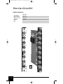
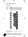
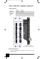
Video Distribution Amplifier Expansion
Product Comparison
Inputs/Outputs
Input Connectors
Output Connectors
Bandwidth
Output On/Off
Ind. Buffered Outputs
Slots
MT103-101
8-out expansion
internal
BNC female
350 MHz
9
9
1
MT103-106
MT103-101
1
1
2
2
2
3
3
3
4
4
4
5
5
5
6
6
6
7
7
7
8
VIDEO DA
9
1
1
OUT
1
8
MT103-112
8-out expansion
internal
BNC female
250 MHz
MT103-112
OUT
OUT
MT103-106
8-out expansion
internal
BNC female
350 MHz
8
VIDEO DA
VIDEO DA
RS-232 Control Commands
[CnUi], [GkUi], [VERCnUi], [ONmCnUi], [OFFmCnUi], [SW], [WRCnCoCpCq...GkUi],
[RDGkUi], [CLRGkUi]
14
ALTINEX, Inc. • Toll Free: 800-ALTINEX • Tel: 714-990-2300 • Fax: 714-990-3303 • Web: www.altinex.com
MT Book #3.qxd
3/19/03
5:03 PM
Page 15
®
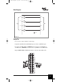
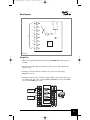
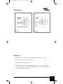
Block Diagrams
EXP 1
EXP 2
EXP 3
EXP 4
EXP 1
EXP 2
POWER
EXP 3
EXP 4
POWER
OUTPUT 1
OUTPUT 1
OUTPUT 2
OUTPUT 2
OUTPUT 3
OUTPUT 3
OUTPUT 4
OUTPUT 4
BNC
BNC
OUTPUT 5
OUTPUT 5
OUTPUT 6
OUTPUT 6
OUTPUT
ON/OFF
CONTROL
OUTPUT 7
OUTPUT 7
OUTPUT 8
OUTPUT 8
MT103-101
EXP 1
EXP 2
MT103-106
EXP 3
EXP 4
POWER
OUTPUT 1
OUTPUT 2
OUTPUT 3
OUTPUT 4
OUTPUT 5
BNC
OUTPUT 6
OUTPUT 7
OUTPUT 8
MT103-112
Design Tips
• Economical NTSC, PAL, SECAM and HDTV (Y, Pb, Pr) signal distribution with MT103-112
• Computer-grade bandwidth (up to QXGA), with MT103-101 and MT103-106
• Use multiple cards side by side to handle S-Video (two cards), component video or RGsB
(three cards), RGBS (four cards), and RGBHV (five cards)
• Normally uses MT103-100 or MT103-111 for internal input, but may also be used with
video switching expansion cards
ALTINEX, Inc. • Toll Free: 800-ALTINEX • Tel: 714-990-2300 • Fax: 714-990-3303 • Web: www.altinex.com
15
MT Book #3.qxd
3/19/03
5:03 PM
Page 16
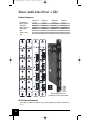
Video Line Driver/GLI
Product Comparison
MT103-113
4-in 4-out
BNC female
BNC female
350 MHz
9
1
Inputs/Outputs
Input Connectors
Output Connectors
Bandwidth
GLI
Slots
MT103-113
IN
1
OUT
IN
2
OUT
IN
3
OUT
IN
4
OUT
VIDEO DRIVER
16
ALTINEX, Inc. • Toll Free: 800-ALTINEX • Tel: 714-990-2300 • Fax: 714-990-3303 • Web: www.altinex.com
MT Book #3.qxd
3/19/03
5:03 PM
Page 17
®
Block Diagrams
IINPUT 1
GLI
OUTPUT 1
INPUT 2
GLI
OUTPUT 2
BNC
BNC
INPUT 3
GLI
OUTPUT 3
INPUT 4
GLI
OUTPUT 4
POWER
MT103-113
Design Tips
• Use to prevent or remove “hum bars” in video image
• Compatible with NTSC, PAL and SECAM (Composite, S-Video, and HDTV) signals
• To convert 15-pin HD to BNCs use MS8102CA (six foot/1.8 meter, 15-pin HD male to
five-BNC male) or MS8106CA (six foot/1.8 meter, 15-pin HD male to five-BNC female)
• Supports RGBHV, RGBS, and RGsB format signals as well (may require multiple cards)
MT103-113
IN
MT103-113
IN
R
1
OUT
1
OUT
V
IN
IN
G
2
OUT
2
OUT
MAIN OUTPUT
COMPUTER
INPUT
V SYNC
GREEN
LOCAL MONITOR
OUTPUT
RED
H/C SYNC
BLUE
IN
IN
B
3
Workstation +
VA6803SX Interface
OUT
3
OUT
IN
IN
OUT
OUT
Projector
H
4
VIDEO DRIVER
4
VIDEO DRIVER
ALTINEX, Inc. • Toll Free: 800-ALTINEX • Tel: 714-990-2300 • Fax: 714-990-3303 • Web: www.altinex.com
17
MT Book #3.qxd
3/19/03
5:03 PM
Page 18
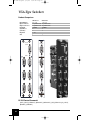
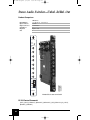
S-Video Distribution Amplifiers
Product Comparison
Inputs/Outputs
Input Connectors
Output Connectors
Bandwidth
Ind. Buffered Outputs
Output On/Off
Slots
MT103-117
1-in 6-out
4-pin mini DIN female
4-pin mini DIN female
60MHz
1
MT103-117
IN
MT103-119
1-in 6-out
4-pin mini DIN female
4-pin mini DIN female
60 MHz
9
9
1
MT103-119
OUT6
OUT 6
OUT5
OUT5
OUT4
OUT4
OUT 3
OUT 3
OUT2
OUT2
OUT 1
OUT 1
IN
S-VIDEO
DA
S-VIDEO
DA
RS-232 Control Commands
[CnUi], [GkUi], [VERCnUi], [ONmCnUi], [OFFmCnUi], [SW], [WRCnCoCpCq...GkUi],
[RDGkUi], [CLRGkUi]
18
ALTINEX, Inc. • Toll Free: 800-ALTINEX • Tel: 714-990-2300 • Fax: 714-990-3303 • Web: www.altinex.com
MT Book #3.qxd
3/19/03
5:03 PM
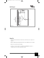
Page 19
®
Block Diagrams
OUTPUT 1
SIGNAL
PRESENT
OUTPUT 1
POWER
SIGNAL
PRESENT
POWER
OUTPUT 2
OUTPUT 2
OUTPUT 3
OUTPUT 3
4 PIN
MINI-DIN
INPUT 1
4 PIN
MINI DIN
OUTPUT 4
4 PIN MINI-DIN
INPUT 1
OUTPUT 4
4 PIN MINI DIN
OUTPUT 5
OUTPUT 5
OUTPUT 6
OUTPUT
ON/OFF
CONTROL
MT103-117
OUTPUT 6
MT103-119
Design Tips
• Use the MT103-117 for high-quality S-Video distribution
• Use the MT103-119 for applications requiring output on-off control
• Can also be used as dual composite distribution amplifier with 4-pin mini-DIN to BNC
adapter
• Adapt S-Video connectors to female BNC ends using ALTINEX MS8135MG (12 inch/30.5
centimeter, four-pin mini DIN male to two-BNC female)
Video
Luma
Composite Video
#1
Composite Video
#2
OUT6
OUT6
OUT5
OUT5
OUT4
OUT4
OUT3
OUT3
OUT2
OUT2
OUT 1
Video
Chroma
MT103-117
IN
OUT1
MT103-117
IN
S-VIDEO
DA
S-VIDEO
DA
ALTINEX, Inc. • Toll Free: 800-ALTINEX • Tel: 714-990-2300 • Fax: 714-990-3303 • Web: www.altinex.com
19
MT Book #3.qxd
3/19/03
5:03 PM
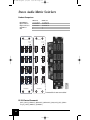
Page 20
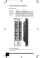
Dual Video/S-Video Distribution Amplifiers
Product Comparison
MT103-118
Dual separate 1-in 3-out
BNC female & 4-pin mini DIN female
BNC female & 4-pin mini DIN female
60 MHz
Inputs/Outputs
Input Connectors
Output Connectors
Bandwidth
Ind. Buffered Outputs
Output On/Off
Slots
1
MT103-118
IN
MT103-120
Dual separate 1-in 3-out
BNC female & 4-pin mini DIN female
BNC female & 4-pin mini DIN female
60 MHz
9
9
1
MT103-120
OUT3
OUT 3
OUT2
OUT 2
OUT 1
OUT 1
IN
IN
IN
OUT1
OUT1
OUT2
OUT2
OUT3
OUT3
VIDEO / S-VIDEO
DA
VIDEO / S-VIDEO
DA
RS-232 Control Commands
[CnUi], [GkUi], [VERCnUi], [ONmCnUi], [OFFmCnUi], [SW], [WRCnCoCpCq...GkUi],
[RDGkUi], [CLRGkUi]
20
ALTINEX, Inc. • Toll Free: 800-ALTINEX • Tel: 714-990-2300 • Fax: 714-990-3303 • Web: www.altinex.com
MT Book #3.qxd
3/19/03
5:03 PM
Page 21
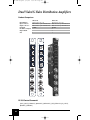
®
Block Diagrams
POWER
POWER
OUTPUT 1
OUTPUT 1
INPUT 1
OUTPUT 2
INPUT 1
4 PIN
MINI-DIN
4 PIN
MINI-DIN
4 PIN
MINI-DIN
OUTPUT 2
4 PIN
MINI-DIN
OUTPUT 3
OUTPUT 3
OUTPUT 1
OUTPUT 1
INPUT 1
OUTPUT 2
INPUT 1
VIDEO
BNC
OUTPUT 2
VIDEO
BNC
VIDEO
BNC
VIDEO
BNC
OUTPUT 3
OUTPUT 3
OUTPUT
ON/OFF
MT103-118
MT103-120
Design Tips
• Use the MT103-118 for high-quality composite and S-Video distribution
• Use the MT103-120 for applications requiring output on-off control
• Adapt S-Video connectors to female BNC ends using ALTINEX MS8135MG
(12 inch/30.5 centimeter, four-pin mini DIN male to two-BNC female)
MT103-120
Chroma
IN
OUT3
OUT2
OUT 1
Luma
IN
OUT1
OUT2
OUT3
VIDEO / S-VIDEO
DA
ALTINEX, Inc. • Toll Free: 800-ALTINEX • Tel: 714-990-2300 • Fax: 714-990-3303 • Web: www.altinex.com
21
MT Book #3.qxd
3/19/03
5:03 PM
Page 22
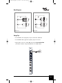
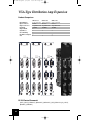
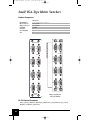
VGA-Type Distribution Amplifiers
Product Comparison
MT103-102
1-in 3-out
15-pin HD female
15-pin HD female
350 MHz
9
9
9
9
1 card
1
Inputs/Outputs
Input Connectors
Output Connectors
Bandwidth
Output On/Off
Signal Detect
Screen Blanking
Ind. Buffered Outputs
Expansion
Slots
MT103-102
MT103-103
MT103-103
1-in 6-out
15-pin HD female
15-pin HD female
350 MHz
9
9
9
9
1 card
2
MT103-107
MT103-107
1-in 3-out
15-pin HD female
15-pin HD female
250 MHz
MT103-108
1-in 6-Out
15-pin HD female
15-pin HD female
250 MHz
9
1
2
MT103-108
INPUT
INPUT
INPUT
INPUT
RED POWER/
GREEN SIGNAL
RED POWER/
GREEN SIGNAL
POWER
OUTPUT
RED POWER/
GREEN SIGNAL
OUTPUT 1
OUTPUT 1
OUTPUT
1
5
2
6
3
4
1
5
2
6
3
OU TPUT 3
OU TPUT 3
OUT PU T 2
OUT PU T 2
4
RS-232 Control Commands
[CnUi], [GkUi], [VERCnUi], [ONmCnUi], [OFFmCnUi], [SW], [WRCnCoCpCq...GkUi],
[RDGkUi], [CLRGkUi]
22
ALTINEX, Inc. • Toll Free: 800-ALTINEX • Tel: 714-990-2300 • Fax: 714-990-3303 • Web: www.altinex.com
MT Book #3.qxd
3/19/03
5:03 PM
Page 23
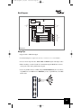
®
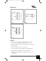
Block Diagrams
EXP 1
EXP 1
SIGNAL
DETECT
POWER
OUTPUT 1
OUTPUT 1
OUTPUT 2
OUTPUT 3
15-PIN HD
INPUT
15-PIN HD
OUTPUT 2
15-PIN HD
INPUT
15-PIN HD
OUTPUT 4
PLUG AND PLAY
PLUG AND PLAY
SIGNAL
DETECT
POWER
OUTPUT 5
ON/OFF
CONTROL,
ON/OFF
CONTROL,
OUTPUT 3
SCREEN
BLANKING
OUTPUT 6
SCREEN
BLANKING
MT103-102
MT103-103
SIGNAL
POWER
POWER
OUTPUT 1
OUTPUT 1
OUTPUT 2
OUTPUT 3
INPUT
15-PIN HD
OUTPUT 2
15-PIN HD
15-PIN
HD
INPUT
15-PIN HD
OUTPUT 4
PLUG AND PLAY
PLUG AND PLAY
OUTPUT 5
OUTPUT 6
OUTPUT 3
MT103-107
MT103-108
Design Tips
• Economical, high-quality VGA through UXGA distribution with MT103-107 (three-out)
and MT103-108 (six-out)
• High-bandwidth (VGA through QXGA) distribution, expansion, screen blanking, and output on-off control with MT103-102 (three-out) and MT103-103 (six-out)
• Convert 15-pin HD connectors to BNCs using ALTINEX MS8102CA (six foot, 15-pin
HD male to five-BNC male) or MS8106CA (six foot/1.8 meter, 15-pin HD male to five-BNC
female) cables
• Expand total available outputs using VGA-Type Distribution Amplifier Expansion Cards
(MT103-104, MT103-109, MT103-110; see next page for more info)
• True VESA Plug and Play on inputs for graphics-mode compatibility
ALTINEX, Inc. • Toll Free: 800-ALTINEX • Tel: 714-990-2300 • Fax: 714-990-3303 • Web: www.altinex.com
23
MT Book #3.qxd
3/19/03
5:03 PM
Page 24
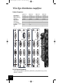
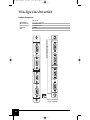
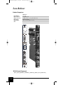
VGA-Type Distribution Amp Expansion
Product Comparison
Inputs/Outputs
Input Connectors
Output Connectors
Bandwidth
Output On/Off
Signal Detect
Screen Blanking
Ind. Buffered Outputs
Slots
MT103-104
6-out (expansion)
internal
15-pin HD female
350 MHz
9
9
9
9
2
MT103-109
MT103-104
MT103-110
6-out (expansion)
internal
15-pin HD female
350 MHz
9
9
2
9
2
MT103-110
RED POWER/
GREEN SIGNAL
RED POWER/
GREEN SIGNAL
RED POWER/
GREEN SIGNAL
OUTPUT
OUTPUT
MT103-109
6-out (expansion)
internal
15-pin HD female
250 MHz
OUTPUT
4
1
4
1
4
1
5
2
5
2
5
2
6
3
6
3
6
3
RS-232 Control Commands
[CnUi], [GkUi], [VERCnUi], [ONmCnUi], [OFFmCnUi], [SW], [WRCnCoCpCq...GkUi],
[RDGkUi], [CLRGkUi]
24
ALTINEX, Inc. • Toll Free: 800-ALTINEX • Tel: 714-990-2300 • Fax: 714-990-3303 • Web: www.altinex.com
MT Book #3.qxd
3/19/03
5:03 PM
Page 25
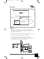
®
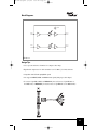
Block Diagrams
EXP 1
SIGNAL
POWER
OUTPUT 1
EXP 1
OUTPUT 2
OUTPUT 1
SIGNAL
POWER
OUTPUT 2
OUTPUT 3
OUTPUT 3
15-PIN HD
15-PIN HD
OUTPUT 4
OUTPUT 5
OUTPUT 4
OUTPUT 6
OUTPUT 5
ON/OFF
CONTROL,
OUTPUT 6
SCREEN
BLANKING
MT103-104
MT103-109
EXP 1
SIGNAL
POWER
OUTPUT 1
OUTPUT 2
OUTPUT 3
15-PIN HD
OUTPUT 4
OUTPUT 5
OUTPUT 6
MT103-110
Design Tips
• Must be used together with main VGA Distribution Amplifier card offering
expansion capability (see MT103-102 and MT103-103 on previous page)
• Expansion accomplished with internal cable bus (single expansion cable included
with expansion card)
• Only one VGA Expansion Card may be used per main card
• Economical, high-quality VGA through UXGA distribution with MT103-109
• High-bandwidth (VGA through QXGA) distribution with MT103-110
• High-bandwidth (QXGA) distribution, screen blanking, and output on-off control
with MT103-104
ALTINEX, Inc. • Toll Free: 800-ALTINEX • Tel: 714-990-2300 • Fax: 714-990-3303 • Web: www.altinex.com
25
MT Book #3.qxd
3/19/03
5:03 PM
Page 26
VGA-Type Line Driver/GLI
Product Comparison
Inputs/Outputs
Input Connectors
Output Connectors
Bandwidth
Slots
MT103-114
2-in 2-out + equalization
15-pin HD female
15-pin HD female
350 MHz
1
MT103-114
MT103-114
OUT
OUT
RED POWER/
GREEN SIGNAL
RED POWER/
GREEN SIGNAL
RED POWER/
GREN SIGNAL
IN
RED POWER/
GREN SIGNAL
IN
IN
IN
OUT
OUT
Advance information;
call for availability
26
ALTINEX, Inc. • Toll Free: 800-ALTINEX • Tel: 714-990-2300 • Fax: 714-990-3303 • Web: www.altinex.com
MT Book #3.qxd
3/19/03
5:03 PM
Page 27
®
Block Diagrams
POWER
INPUT 1
15-PIN HD
GLI
INPUT 2
15-PIN HD
GLI
EQ
OUTPUT 1
15-PIN HD
EQ
OUTPUT 2
15-PIN HD
HW
HW
MT103-114
Design Tips
• Use to prevent and remove “hum bars” in computer video image
• Equalization compensates for cable attenuation over 25–300 ft. (7.6–91m) cable runs
• Compatible with VGA through QXGA signals
• Also supports RGBHV, RGBS, and RGsB format signals (with proper cable adapter)
• To convert 15-pin HD to BNCs use MS8102CA (six foot/1.8 meter, 15-pin HD male to
five-BNC male) or MS8106CA (six foot/1.8 meter, 15-pin HD male to five-BNC female)
MT103-114
OUT
R
G
IN
B
H
V
IN
OUT
ALTINEX, Inc. • Toll Free: 800-ALTINEX • Tel: 714-990-2300 • Fax: 714-990-3303 • Web: www.altinex.com
27
MT Book #3.qxd
3/19/03
5:03 PM
Page 28
Video Switchers
Product Comparison
MT104-100
6-in 1-out
BNC female
BNC female
350 MHz
9
9
2 cards
1
Inputs/Outputs
Input Connectors
Output Connectors
Bandwidth
Output On/Off
Signal Detect
Expansion
Slots
MT104-100
MT104-103
6-in 1-out
BNC female
BNC female
350 MHz
9
1
MT104-103
RED POWER/
GREEN SIGNAL
POWER
OUT
OUT
IN
IN
1
1
2
2
3
3
4
4
5
5
6
6
VIDEO SW
VIDEO SW
RS-232 Control Commands
[CnUi], [GkUi], [VERCnUi], [ONmCnUi], [OFFmCnUi], [SW], [WRCnCoCpCq...GkUi],
[RDGkUi], [CLRGkUi]
28
ALTINEX, Inc. • Toll Free: 800-ALTINEX • Tel: 714-990-2300 • Fax: 714-990-3303 • Web: www.altinex.com
MT Book #3.qxd
3/19/03
5:03 PM
Page 29
®
Block Diagrams
INPUT 1
INPUT 1
SIGNAL
POWER
POWER
INPUT 2
INPUT 2
INPUT 3
INPUT 3
BNC
BNC
OUTPUT
BNC
INPUT 4
OUTPUT
BNC
INPUT 4
INPUT 5
INPUT 5
INPUT 6
INPUT SELECT
CONTROL
INPUT SELECT
CONTROL
INPUT 6
OUTPUT ON/OFF
OUTPUT ON/OFF
INPUT 7
INPUT 8
MT104-100
MT104-103
Design Tips
• Designed for composite video switching and (using multiple cards installed side-by-side)
can switch S-Video (two cards), component, HDTV and RGsB video (three cards), RGBS
(four cards) and RGBHV (five cards)
• Use MT104-100 to expand up to 22 inputs through internal connection of up to two expansion cards — see MT104-101
• Output can be disabled, allowing multiple outputs to be looped for even further expansion
• VIS (Vertical Interval Switching — eliminates switching “glitch”) available by special order
• Switching is controlled via RS-232 commands through the MultiTasker enclosure, or
through push-button front panel
Y
Pb
MT104-100
RED POWER/
GREEN SIGNAL
MT104-100
RED POWER/
GREEN SIGNAL
OUT
HD-VTR
HD-VTR
MT104-100
RED POWER/
GREEN SIGNAL
OUT
IN
HD-VTR
Pr
OUT
IN
IN
1
1
1
2
2
2
3
3
3
4
4
4
5
5
5
6
6
VIDEO SW
HDTV Projector
6
VIDEO SW
VIDEO SW
ALTINEX, Inc. • Toll Free: 800-ALTINEX • Tel: 714-990-2300 • Fax: 714-990-3303 • Web: www.altinex.com
29
MT Book #3.qxd
3/19/03
5:03 PM
Page 30
Video Switcher Expansion
Product Comparison
Inputs/Outputs
Input Connectors
Output Connectors
Bandwidth
Output On/Off
Slots
MT104-101
8-in expansion
BNC female
internal
350 MHz
9
1
MT104-101
IN
1
2
3
4
5
6
7
8
VIDEO SW
RS-232 Control Commands
[CnUi], [GkUi], [VERCnUi], [ONmCnUi], [OFFmCnUi], [SW], [WRCnCoCpCq...GkUi],
[RDGkUi], [CLRGkUi]
30
ALTINEX, Inc. • Toll Free: 800-ALTINEX • Tel: 714-990-2300 • Fax: 714-990-3303 • Web: www.altinex.com
MT Book #3.qxd
3/19/03
5:03 PM
Page 31
®
Block Diagrams
EXP 2
EXP 1
INPUT 1
INPUT 2
INPUT 3
INPUT 4
BNC
INPUT 5
POWER
INPUT 6
INPUT SELECT
CONTROL
OUTPUT ON/OFF
INPUT 7
INPUT 8
MT104-101
Design Tips
• Must be used together with main Video Switcher Card (MT104-100) offering expansion
capability
• Expansion accomplished with internal cable bus (single expansion cable included with
expansion card)
• Switching controlled via RS-232 commands or front panel control through the
MultiTasker enclosure
• Designed for composite video switching, and (using multiple cards installed side-by-side)
can switch S-Video (two cards), component, HDTV and RGsB video (three cards), RGBS
(four cards) and RGBHV (five cards)
Workstation 1
MT104-101
1
1
2
2
3
3
S-VHS
DVD
Workstation 4
MT104-100
IN
4
4
5
5
RED POWER/
GREEN SIGNAL
RED POWER/
GREEN SIGNAL
OUT
OUT
IN
IN
S-Video
Workstation 3
MT104-100
MT104-101
IN
1
1
2
2
3
3
4
4
5
5
6
6
Projector
Hi-8
6
6
7
7
Workstation 2
8
Internal IDC Cable
8
VIDEO SW
S-Video
VIDEO SWITCH
VIDEO SWITCH
VIDEO SW
ALTINEX, Inc. • Toll Free: 800-ALTINEX • Tel: 714-990-2300 • Fax: 714-990-3303 • Web: www.altinex.com
31
MT Book #3.qxd
3/19/03
5:03 PM
Page 32
S-Video Switcher
Product Comparison
Inputs/Outputs
Input Connectors
Output Connectors
Bandwidth
Output On/Off
Slots
MT104-108
6-in 1-out
4-pin mini DIN female
4-pin mini DIN female
60 MHz
9
1
MT104-108
OUT
IN1
IN2
IN3
IN4
IN5
IN6
S-VIDEO
SWITCHER
RS-232 Control Commands
[CnUi], [GkUi], [VERCnUi], [ONmCnUi], [OFFmCnUi], [SW], [WRCnCoCpCq...GkUi],
[RDGkUi], [CLRGkUi]
32
ALTINEX, Inc. • Toll Free: 800-ALTINEX • Tel: 714-990-2300 • Fax: 714-990-3303 • Web: www.altinex.com
MT Book #3.qxd
3/19/03
5:03 PM
Page 33
®
Block Diagrams
INPUT 1
POWER
INPUT 2
INPUT3
4-PIN
MINI DIN
OUTPUT
4-PIN MINI DIN
INPUT4
INPUT5
INPUT SELECT,
OUTPUT ON/OFF
CONTROL
INPUT 6
MT104-108
Design Tips
• Compatible with NTSC, PAL and SECAM
• Switching is controlled via RS-232 commands or front panel control through the MultiTasker enclosure
• Auto-switching option available by custom order
• Adapt S-Video connectors to BNC ends using ALTINEX MS8135MG (12 inch/30.5 centimeter, 4-pin mini-DIN male to two-BNC female)
MT104-108
OUT
IN1
Chroma
Luma
IN2
IN3
IN4
IN5
IN6
S-VIDEO
SWITCHER
ALTINEX, Inc. • Toll Free: 800-ALTINEX • Tel: 714-990-2300 • Fax: 714-990-3303 • Web: www.altinex.com
33
MT Book #3.qxd
3/19/03
5:03 PM
Page 34
Dual Video/S-Video Switcher
Product Comparison
Inputs/Outputs
Input Connectors
Output Connectors
Bandwidth
Input Off
Slots
MT104-107
Dual separate 3-in 1-out
BNC female/4-pin mini DIN female
BNC female/4-pin mini DIN female
60 MHz
9
1
MT104-107
OUT
IN1
IN2
IN3
IN1
IN2
IN3
OUT
VIDEO / S-VIDEO
SWITCHER
RS-232 Control Commands
[CnUi], [GkUi], [VERCnUi], [ONmCnUi], [OFFmCnUi], [SW], [WRCnCoCpCq...GkUi],
[RDGkUi], [CLRGkUi]
34
ALTINEX, Inc. • Toll Free: 800-ALTINEX • Tel: 714-990-2300 • Fax: 714-990-3303 • Web: www.altinex.com
MT Book #3.qxd
3/19/03
5:03 PM
Page 35
®
Block Diagrams
POWER
INPUT OFF
INPUT 1
4-PIN MINI DIN
OUTPUT
4-PIN MINI DIN
INPUT 2
INPUT 3
INPUT OFF
INPUT 1
BNC
OUTPUT
BNC
INPUT 2
INPUT 3
INPUT SELECT
CONTROL
MT104-107
Design Tips
• Compatible with NTSC, PAL and SECAM
• Independent composite video and S-Video channel switching
• Auto-switching option available by custom order
• Switching is controlled via RS-232 commands or front panel control through the MultiTasker enclosure
• Adapt S-Video connectors to BNC ends using ALTINEX MS8135MG (12 inch/30.5
centimeter, 4-pin mini DIN male to two BNC female)
MT104-107
OUT
IN1
S-VHS
IN2
IN3
DVD
Video Projector
IN1
Laserdisc
IN2
IN3
VHS
OUT
VIDEO / S-VIDEO
SWITCHER
ALTINEX, Inc. • Toll Free: 800-ALTINEX • Tel: 714-990-2300 • Fax: 714-990-3303 • Web: www.altinex.com
35
MT Book #3.qxd
3/19/03
5:04 PM
Page 36
VGA-Type Switchers
Product Comparison
MT104-102
6-in 1-out
15-pin HD female
15-pin HD female
350 MHz
9
9
1 card
2
Inputs/Outputs
Input Connectors
Output Connectors
Bandwidth
Signal Detect
Sync Delay
Expansion
Slots
MT104-102
MT104-105
3-in 1-out
15-pin HD female
15-pin HD female
350 MHz
9
9
1
MT104-105
OUTPUT
OUTPUT
INPUT 1
INPUT
INPUT 2
1
5
3
6
INPUT 3
2
RS-232 Control Commands
[CnUi], [GkUi], [VERCnUi], [ONmCnUi], [OFFmCnUi], [SW], [WRCnCoCpCq...GkUi],
[RDGkUi], [CLRGkUi]
36
ALTINEX, Inc. • Toll Free: 800-ALTINEX • Tel: 714-990-2300 • Fax: 714-990-3303 • Web: www.altinex.com
MT Book #3.qxd
3/19/03
5:04 PM
Page 37
®
Block Diagrams
SIGNAL
POWER
INPUT 1
SIGNAL
INPUT 1
Plug and Play
POWER
Plug and Play
15-PIN HD
OUTPUT
15-PIN HD
INPUT 2
Plug and Play
INPUT 2
Plug and Play
INPUT 3
Plug and Play
INPUT 3
Plug and Play
15-PIN HD
INPUT SELECT
CONTROL
OUTPUT
15-PIN
INPUT 4
Plug and Play
INPUT 5
Plug and Play
INPUT 6
Plug and Play
INPUT SELECT
CONTROL
INPUT 7
MT104-102
MT104-105
Design Tips
• Supports VGA through QXGA throughput
• Use MT104-102 if input expansion is required. The MT104-102 is expandable by one
card via an internal cable — see MT104-104 and MT104-106 VGA-Type Switcher
Expansion Cards
• Also capable of switching RGsB, RGBS and RGBHV formats (requires cable adapters)
• Auto-switching option available by custom order
• Convert 15-pin HD connectors to BNCs using ALTINEX MS8102CA (six foot/1.8 meter,
15-pin HD male to five-BNC male) or MS8106CA (six foot/1.8 meter, 15-pin HD male
to five-BNC female) cables
• Switching is controlled via RS-232 commands or front panel control through the MultiTasker enclosure
OUTPUT
MT104-105
SK2002DA
INPUT 1
Computer
Computer
INPUT 2
SK2002DA
Plasma Display
INPUT 3
SK2002DA
Computer
ALTINEX, Inc. • Toll Free: 800-ALTINEX • Tel: 714-990-2300 • Fax: 714-990-3303 • Web: www.altinex.com
37
MT Book #3.qxd
3/19/03
5:04 PM
Page 38
VGA-Type Switcher Expansion
Product Comparison
MT104-104
6-in (expansion)
15-pin HD female
internal
350 MHz
9
1 card
2
Inputs/Outputs
Input Connectors
Output Connectors
Bandwidth
Sync Delay
Expansion
Slots
MT104-106
3-in (expansion)
15-pin HD female
internal
350 MHz
9
1 card
1
MT104-104
MT104-106
POWER
POWER
INPUT 1
INPUT
1
5
2
INPUT 3
INPUT 2
4
6
VGA SW
RS-232 Control Commands
[CnUi], [GkUi], [VERCnUi], [ONmCnUi], [OFFmCnUi], [SW], [WRCnCoCpCq...GkUi],
[RDGkUi], [CLRGkUi]
38
ALTINEX, Inc. • Toll Free: 800-ALTINEX • Tel: 714-990-2300 • Fax: 714-990-3303 • Web: www.altinex.com
MT Book #3.qxd
3/19/03
5:04 PM
Page 39
®
Block Diagrams
EXP 1
EXP 1
POWER
POWER
INPUT 1
Plug and Play
INPUT 2
Plug and Play
INPUT 1
Plug and Play
INPUT 3
Plug and Play
15-PIN HD
15-PIN HD
INPUT 2
Plug and Play
INPUT 4
Plug and Play
INPUT 3
Plug and Play
INPUT 5
Plug and Play
INPUT SELECT
CONTROL
INPUT 6
INPUT SELECT
CONTROL
Plug and Play
MT104-104
MT104-106
Design Tips
• Supports VGA through QXGA throughput
• Connects to VGA-type switcher cards via internal cable — see MT104-102
• Auto-switching option available by custom order
• Convert 15-pin HD connectors to BNCs using ALTINEX MS8102CA (six foot/1.8 meter,
15-pin HD male to five-BNC male) or MS8106CA (six foot/1.8 meter, 15-pin HD male
to five-BNC female) cables
• Switching is controlled via RS-232 commands or front panel control through the MultiTasker enclosure
SK2002DA
MT104-104
SK2002DA
SK2002DA
MT104-102
OUTPUT
Computer
INPUT
Computer
SK2002DA
4
1
SK2002DA
Computer
INPUT
SK2002DA
1
4
Projector
Computer
5
2
SK2002DA
Computer
SK2002DA
6
Computer
IDC Cable
to
MT104-102
Computer
IDC Cable
from
MT104-104
3
Computer
2
5
3
6
SK2002DA
Computer
ALTINEX, Inc. • Toll Free: 800-ALTINEX • Tel: 714-990-2300 • Fax: 714-990-3303 • Web: www.altinex.com
39
MT Book #3.qxd
3/19/03
5:04 PM
Page 40
Small Video Matrix Switchers
Product Comparison
Inputs/Outputs
Input Connectors
Output Connectors
Bandwidth
Slots
MT105-106
2 x 6, 3 x 5, 4 x 4, 5 x 3, or 6 x 2
BNC female
BNC female
200 MHz
1
IN 2
IN 3/OUT 6
IN 4/OUT 5
IN 5/OUT 4
IN 6/OUT 3
OUT 2
OUT 1
MT105-106
IN 1
IN 2
IN 3/OUT 6
IN 4/OUT 5
IN 5/OUT 4
IN 6/OUT 3
OUT 2
OUT 1
MT105-106
IN 1
VIDEO MATRIX
VIDEO MATRIX
Advance information;
call for availability
RS-232 Control Commands
[CnUi], [GkUi], [VERCnUi], [ONmCnUi], [OFFmCnUi], [SW], [WRCnCoCpCq...GkUi],
[RDGkUi], [CLRGkUi], [IxOyCnUi]
40
ALTINEX, Inc. • Toll Free: 800-ALTINEX • Tel: 714-990-2300 • Fax: 714-990-3303 • Web: www.altinex.com
MT Book #3.qxd
3/19/03
5:04 PM
Page 41
®
Block Diagrams
POWER
MATRIX
CONTROL
OUTPUT
INPUT 1
1
1
INPUT 2
2
2
MALE BNC
OUTPUT 2
3
4
5
6
6
OUT 6
5
OUT 4
4
6x6
MATRIX SWITCHER
OUTPUT 1
OUT 3
3
OUT 5
MALE BNC
INPUT 6
IN 6/OUT 3
INPUT 5
IN 5/OUT 4
MALE BNC
INPUT 4
IN 4/OUT 5
INPUT 3
IN 3/OUT 6
MT105-106
Design Tips
• Use internal jumpers to set up for use as 2 x 6, 3 x 5, 4 x 4, 5 x 3, or 6 x 2 matrix
• Use multiple cards for multi-signal formats, i.e., two cards for S-Video, three for RGB or
component, five for RGBHV
• May be used as 1 x 3, 2 x 2 or 3x1 S-Video matrix using 2 BNCs per source (chroma/luma)
• Matrix switching is controlled via RS-232 commands through the MultiTasker enclosure,
or front panel control with a push-button front panel
• For S-Video sources, adapt two BNCs to a four-pin mini-DIN using ALTINEX
MS8132MG (12 inch/30.5 cm, four-pin mini-DIN male to two-BNC male) or ALTINEX
MS8133MG (12 inch/30.5 cm, four-pin mini-DIN female to two-BNC male)
MS8133MG
IN 5/OUT 4
S-VHS
IN 6/OUT 3
OUT 2
OUT 1
MT105-106
IN 3/OUT 6
IN 4/OUT 5
MS8133MG
IN 2
DVD
IN 1
Video Projector
MATRIX
S-VHS
ALTINEX, Inc. • Toll Free: 800-ALTINEX • Tel: 714-990-2300 • Fax: 714-990-3303 • Web: www.altinex.com
41
MT Book #3.qxd
3/19/03
5:04 PM
Page 42
Mid-Size Video Matrix Switchers
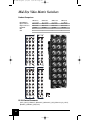
Product Comparison
MT105-100
16 x 8 matrix
BNC female
BNC female
350 MHz
9
3
Inputs/Outputs
Input Connectors
Output Connectors
Bandwidth
GLI
Slots
MT 105-100
MT105-101
16 x 8 matrix
BNC female
BNC female
200 MHz
3
1
1
1
1
10
2
2
2
2
11
3
3
3
3
12
4
4
4
4
13
5
5
5
5
14
6
6
6
6
15
7
7
7
7
8
8
INPUT
8
OUTPUT
OUTPUT
MT 105-103
9
1
1
1
1
10
2
2
2
2
11
3
3
3
3
12
4
4
4
4
13
5
5
5
5
14
6
6
6
6
15
7
7
7
7
8
8
INPUT
2
8
INPUT
MT 105-101
16
MT105-103
8 x 8 Matrix
BNC female
BNC female
200 MHz
MT 105-102
9
16
MT105-102
8 x 8 matrix
BNC female
BNC female
350 MHz
9
2
8
OUTPUT
8
INPUT
OUTPUT
RS-232 Control Commands
[CnUi], [GkUi], [VERCnUi], [ONmCnUi], [OFFmCnUi], [SW], [WRCnCoCpCq...GkUi],
[RDGkUi], [CLRGkUi], [IxOyCnUi]
42
ALTINEX, Inc. • Toll Free: 800-ALTINEX • Tel: 714-990-2300 • Fax: 714-990-3303 • Web: www.altinex.com
MT Book #3.qxd
3/19/03
5:04 PM
Page 43
®
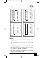
Block Diagrams
INPUT 1
GLI
INPUT 2
GLI
INPUT 3
GLI
INPUT 4
GLI
INPUT 5
GLI
INPUT 6
GLI
INPUT 7
GLI
INPUT 8
GLI
INPUT 9
GLI
INPUT 10
GLI
INPUT 11
GLI
INPUT 12
GLI
INPUT 13
GLI
INPUT 14
GLI
INPUT 15
GLI
INPUT 16
GLI
INPUT 1
OUTPUT 1
INPUT 2
OUTPUT 1
MATRIX
SWITCHER
INPUT 3
MATRIX
SWITCHER
OUTPUT 2
INPUT 4
OUTPUT 2
INPUT 5
OUTPUT 3
INPUT 6
OUTPUT 3
INPUT 7
OUTPUT 4
INPUT 8
OUTPUT 4
BNC
BNC
OUTPUT 5
INPUT 10
OUTPUT 5
INPUT 11
OUTPUT 6
INPUT 12
OUTPUT 6
INPUT 13
OUTPUT 7
INPUT 14
OUTPUT 7
INPUT 15
OUTPUT 8
INPUT 16
OUTPUT 8
MATRIX
CONTROL
MATRIX
CONTROL
MT105-100
INPUT 1
BNC
INPUT 9
BNC
MT105-101
GLI
INPUT 1
OUTPUT 1
OUTPUT 1
MATRIX
SWITCHER
MATRIX
SWITCHER
INPUT 2
GLI
OUTPUT 2
INPUT 2
OUTPUT 2
INPUT 3
GLI
OUTPUT 3
INPUT 3
OUTPUT 3
INPUT 4
GLI
OUTPUT 4
INPUT 4
OUTPUT 4
BNC
BNC
BNC
BNC
INPUT 5
GLI
OUTPUT 5
INPUT 5
OUTPUT 5
INPUT 6
GLI
OUTPUT 6
INPUT 6
OUTPUT 6
INPUT 7
GLI
OUTPUT 7
INPUT 7
OUTPUT 7
INPUT 8
GLI
OUTPUT 8
INPUT 8
MT105-102
OUTPUT 8
MATRIX
CONTROL
MATRIX
CONTROL
MT105-103
Design Tips
• Support composite, S-Video, component, HDTV, RGsB, RGBS, and RGBHV switching
up to UXGA resolutions
• MT105-100 and MT105-102 have GLI (ground loop protection), support up to QXGA
resolutions
• Use multiple cards for multi-signal formats, i.e., two cards for S-Video, three for RGB or
component, five for RGBHV
• Single card inputs can be “ganged” to support multi-signal formats, i.e., 16 x 8 supports
8 x 4 S-Video matrix, 5 x 2 HDTV-RGB, or 4 x 2 RGBS matrix
• Matrix switching is controlled via RS-232 commands through the MultiTasker enclosure,
or front panel control with a push-button front panel
ALTINEX, Inc. • Toll Free: 800-ALTINEX • Tel: 714-990-2300 • Fax: 714-990-3303 • Web: www.altinex.com
43
MT Book #3.qxd
3/19/03
5:04 PM
Page 44
Small VGA-Type Matrix Switchers
Product Comparison
MT105-108
2 x 6, 3 x 5, 4 x 4, 5 x 3, or 6 x 2
(4) 15-pin HD
(4) 15-pin HD
250 MHz
9
9
2
MT105-106
OUT 1
OUT 2
OUT 1
MT105-108
OUT 2
Inputs/Outputs
Input Connectors
Output Connectors
Bandwidth
Sync Delay
Screen Blanking
Slots
POWER
VGS-QXGA
MATRIX
IN 6/OUT 4
IN 4/OUT 6
IN 2
IN 5/OUT 3
IN 3/OUT 5
IN 1
IN 4/OUT 6
IN 2
IN 6/OUT 4
IN 3/OUT 5
IN 1
IN 5/OUT 3
POWER
VGS-QXGA
MATRIX
Advance information;
call for availability
RS-232 Control Commands
[CnUi], [GkUi], [VERCnUi], [ONmCnUi], [OFFmCnUi], [SW], [WRCnCoCpCq...GkUi],
[RDGkUi], [CLRGkUi], [IxOyCnUi]
44
ALTINEX, Inc. • Toll Free: 800-ALTINEX • Tel: 714-990-2300 • Fax: 714-990-3303 • Web: www.altinex.com
MT Book #3.qxd
3/19/03
5:04 PM
Page 45
®
Block Diagrams
POWER
MATRIX
CONTROL
OUTPUT
1
1
OUTPUT 1
PLUG AND PLAY
2
2
OUTPUT 2
PLUG AND PLAY
3
3
15PN HD
4
5
6
6
OUT 6
5
INPUT 6
PLUG AND PLAY
INPUT 5
OUT 3
4
6x6 RGBHV
MATRIX SWITCHER
OUT 4
INPUT 2
OUT 5
INPUT 1
15PN HD
IN 6/OUT 3
IN 5/OUT 4
PLUG AND PLAY
15PN HD
INPUT 4
IN 4/OUT 5
PLUG AND PLAY
INPUT 3
IN 3/OUT 6
PLUG AND PLAY
MT105-108
Design Tips
• Supports VGA to UXGA throughput
• Use internal jumpers to set up for use as 2 x 6, 3 x 5, 4 x 4, 5 x 3, or 6 x 2 matrix
• Can also switch component video, RGsB, RGBS and RGBHV signals with adapter cables
• Matrix switching is controlled via RS-232 commands through the MultiTasker enclosure,
or front panel control with a push-button front panel
• Convert 15-pin HD connectors to BNCs using ALTINEX MS8102CA (six foot/1.8 meter,
15-pin HD male to five-BNC male or MS8106CA (six foot, 15-pin HD male to five-BNC
female) cables
OUT 2
OUT 1
MT105-108
IN 4/OUT 6
IN 6/OUT 4
MS8102CA
IN 2
IN 1
IN 3/OUT 5
IN 5/OUT 3
POWER
MATRIX
ALTINEX, Inc. • Toll Free: 800-ALTINEX • Tel: 714-990-2300 • Fax: 714-990-3303 • Web: www.altinex.com
45
MT Book #3.qxd
3/19/03
5:04 PM
Page 46
CAT-5 Transmitter/Receiver
Product Comparison
MT103-115
2-in 2-out
(2) 15-pin HD
(2) RJ-45
350 MHz
9
9
1
Inputs/Outputs
Inputs Connectors
Output Connectors
Bandwidth
Plug and Play
Equalization
Slots
MT103-116
2-in 2-out
(2) RJ-45
(2) 15-pin HD
350 MHz
9
1
MT103-115
MT103-116
IN
RED POWER/
GREEN SIGNAL
RED POWER/
GREEN SIGNAL
1
1
OUT
OUT
IN
IN
2
2
RED POWER/
GREEN SIGNAL
46
OUT
RED POWER/
GREEN SIGNAL
IN
OUT
VGA TO CAT-5
TRANSMITTER
CAT-5 TO VGA
RECEIVER
ALTINEX, Inc. • Toll Free: 800-ALTINEX • Tel: 714-990-2300 • Fax: 714-990-3303 • Web: www.altinex.com
MT Book #3.qxd
3/19/03
5:04 PM
Page 47
®
Block Diagrams
POWER
POWER
HW
INPUT 1
OUTPUT 1
EQ
INPUT 1
PLUG AND PLAY
15-PIN HD
HW
OUTPUT 1
EQ
RJ-45
RJ-45
15-PIN HD
HW
HW
INPUT 2
INPUT 2
OUTPUT 2
EQ
OUTPUT 2
EQ
PLUG AND PLAY
MT103-115
MT103-116
Design Tips
• Designed for use with ALTINEX compact CAT-5 transmitters and receivers (such as
model numbers DA1920SX and DA1921SX)
• Dual inputs/outputs are completely independent; no switching or distribution occurs
• Supports VGA (at 400 foot/121m) through UXGA (at 250 foot/76m) video resolutions
• Can be used with composite, S-Video, RGsB, RGBS, and RGBHV signals as well; to convert
15-pin HD to BNCs, use ALTINEX MS8102CA (six foot/1.8 meter, 15-pin HD male to fiveBNC male) or MS8106CA (six foot/1.8 meter, 15-pin HD male to five-BNC female)
DA1920SX
MT103-116
CAT-5
OUTPUT
®
CAT-5 TRANSMITTER
OUT
CAT 5 / 5e Cable - Up to 400ft
XGA
XGA
Computer
LOCAL
MONITOR
OUTPUT
EQ
COMPUTER
INPUT
XGA
POWER 9V, 0.5A
RED-POWER
GREEN-SIGNAL
-
+
RED POWER/
GREEN SIGNAL
1
Projector
IN
IN
DVD
MS8135MG
MS8135MG
LOCAL
MONITOR
OUTPUT
CAT-5
OUTPUT
EQ
COMPUTER
INPUT
®
CAT-5 TRANSMITTER
VHS
POWER 9V, 0.5A
RED-POWER
GREEN-SIGNAL
S-Video
2
DA1920SX
MS6406VB
CAT 5 / 5e Cable
Up to 400ft
RED POWER/
GREEN SIGNAL
OUT
MS6406VB
Composite
+
S-Video
-
+
CAT-5 TO VGA
RECEIVER
Composite
ALTINEX, Inc. • Toll Free: 800-ALTINEX • Tel: 714-990-2300 • Fax: 714-990-3303 • Web: www.altinex.com
47
MT Book #3.qxd
3/19/03
5:04 PM
Page 48
Scan Reducer
Product Comparison
Inputs/Outputs
Input Connectors
Output Connectors
Input Signals
Output Signals
Slots
MT106-100
1-in 4-out
15-pin HD female
(3) BNC female + (1) 4-pin mini DIN female
VGA through XGA
Video + S-Video (NTSC and PAL)
1
MT106-100
RED POWER/
GREEN SIGNAL
COMPUTER
INPUT
OUT
S-VIDEO
COMPOSITE
VIDEO
1
2
3
SCAN
REDUCER
RS-232 Control Commands
[CnUi], [GkUi], [RDGkUi], [CLRGkUi], [VERCnUi], [WRxxyyCnUi], [RDxxCnUi]
48
ALTINEX, Inc. • Toll Free: 800-ALTINEX • Tel: 714-990-2300 • Fax: 714-990-3303 • Web: www.altinex.com
MT Book #3.qxd
3/19/03
5:04 PM
Page 49
®
Block Diagrams
SIGNAL
POWER
OUTPUT
4-PIN MINI-DIN
SCAN
REDUCER
INPUT
15-PIN HD
OUTPUT 1
HORIZ. & VERT. POSITION,
ZOOM, PICTURE FREEZE,
BRIGHTNESS,
OVERSCAN/UNDERSCAN,
ANTI-FLICKER
OUTPUT 2
BNC
OUTPUT 3
MT106-100
Design Tips
• Supports VGA (640 x 480) input signals with refresh rates up to 100 Hz, SVGA
(800 x 600) input signals with refresh rates up to 85 Hz, and XGA (1024 x 768) input
signals with refresh rates up to 80 Hz
• Converts non-interlaced computer video signals to interlaced NTSC/PAL video signals
• Four simultaneous outputs: three composite video and one S-Video
• Control of horizontal and vertical positioning, zoom, picture freeze, brightness,
overscan/underscan, and anti-flicker controls via RS-232 through the MultiTasker enclosure,
or through front panel control with a push-button front panel
MT106-100
RED POWER/
GREEN SIGNAL
COMPUTER
INPUT
SK2002DA
VHS
OUT
S-VIDEO
COMPOSITE
VIDEO
1
Video Monitor
Computer
2
Video Monitor
3
SCAN
REDUCER
Video Monitor
ALTINEX, Inc. • Toll Free: 800-ALTINEX • Tel: 714-990-2300 • Fax: 714-990-3303 • Web: www.altinex.com
49
MT Book #3.qxd
3/19/03
5:04 PM
Page 50
Scan Doubler
Product Comparison
Inputs/Outputs
Input Connectors
Output Connectors
Input Signals
Output Signals
Expansion
Slots
MT106-101
4-in 1-out (5th input from expansion)
(3) BNC female + (1) 4-pin mini DIN female
15-pin HD female
Video/S-Video (PAL or NTSC)
VGA (640 x 480)
input: 1 video card
1
MT106-101
RED POWER/
GREEN SIGNAL
INPUT
S-VIDEO
1
2
3
C-VIDEO
VGA OUT
SCAN
DOUBLER
RS-232 Control Commands
[CnUi], [GkUi], [RDGkUi], [CLRGkUi], [VERCnUi], [ONmCnUi], [WRxxyyCnUi],
[RDxxCnUi]
50
MT Book #3.qxd
3/19/03
5:04 PM
Page 51
®
Block Diagrams
EXP 1
SIGNAL
DETECT
POWER
INPUT 0
4-PIN MINI DIN
INPUT 1
BNC
INPUT 2
SCAN
DOUBLER
INPUT 3
OUTPUT
15-PIN HD
INPUT 4
BLACK LEVEL, COLOR,
CONTRAST, BRIGHTNESS,
AND INPUT SWITCHING CONTROL
MT106-101
Design Tips
• Switches between composite or S-video inputs, converts to VGA (640 x 480 @ 60 Hz)
• If other output resolutions are required, please see Scaler Card
• Expandable internally by one switcher card for eight additional composite inputs
• Provides control of black level, color, contrast, and brightness via RS-232 through the
MultiTasker enclosure, or through front panel control with a push-button front panel
MT106-101
RED POWER/
GREEN SIGNAL
INPUT
DVD
S-VIDEO
1
2
Document
Camera
3
C-VIDEO
VCR (Playback)
VGA OUT
SCAN
DOUBLER
Projector
ALTINEX, Inc. • Toll Free: 800-ALTINEX • Tel: 714-990-2300 • Fax: 714-990-3303 • Web: www.altinex.com
51
MT Book #3.qxd
3/19/03
5:04 PM
Page 52
Scaler
Product Comparison
Inputs/Outputs
Input Connectors
Output Connectors
Input Signals
Output Signals
Slots
MT106-102
4-in 1-out
(1) BNC female+(1) 4-pin mini DIN+(1) 15-pin HD female+(1) DVI-D female
15-pin HD female
Video/S-Video/DVI/ VGA-UXGA
VGA to UXGA
1
MT106-102
MT106-102
IN1
IN1
OUT
OUT
IN2
IN2
IN3
IN3
IN4
IN4
SCALER
SCALER
Advance information;
call for availability
RS-232 Control Commands
[CnUi], [GkUi], [VERCnUi], [ONmCnUi], [WRxxyyCnUi], [RDGkUi], [CLRGkUi],
[SELmCnUi], [+], [–]
52
ALTINEX, Inc. • Toll Free: 800-ALTINEX • Tel: 714-990-2300 • Fax: 714-990-3303 • Web: www.altinex.com
MT Book #3.qxd
3/19/03
5:04 PM
Page 53
®
Block Diagrams
SIGNAL
POWER
INPUT 1
DVI-D
INPUT 2
BNC
SCALER
UP/DOWN
INPUT 3
4-PIN MINI DIN
OUTPUT
15-PIN HD
INPUT 4
15-PIN HD
INPUT SELECT
OUTPUT SIGNAL-TYPE SELECT
MT106-102
Design Tips
• Different inputs for composite, S-Video, DVI and VGA-UXGA sources
• Outputs user-defined resolution (VGA through UXGA) on 15-pin HD connector
• Useful for matching a variety of input signals to the native resolution of a projector
• Either 15-pin HD input or output may be converted to BNCs for RGBHV via ALTINEX
MS8102CA (six foot/1.8 meter, 15-pin HD male to five BNC male) or MS8106CA
(six foot/1.8 meter, 15-pin HD male to five BNC female) cables
ALTINEX, Inc. • Toll Free: 800-ALTINEX • Tel: 714-990-2300 • Fax: 714-990-3303 • Web: www.altinex.com
53
MT Book #3.qxd
3/19/03
5:04 PM
Page 54
Stereo Audio Dist. Amplifier—Unbalanced
Product Comparison
MT108-100
1-in 6-out
3.5 mm
dual RCAs
9
9
2
Inputs/Outputs
Input Connectors
Output Connectors
Output On/Off
Signal Detect
Slots
MT108-101
1-in 6-out
3.5 mm
dual RCAs
9
2
MT108-101
MT108-100
RED POWER/
GREEN SIGNAL PRESENT
RED POWER/
GREEN SIGNAL PRESENT
INPUT
INPUT
1
1
R
L
R
L
R
L
R
L
R
L
R
L
R
L
2
2
R
L
3
3
R
L
4
4
R
L
5
5
R
L
6
6
R
L
OUTPUT
OUTPUT
AUDIO DA
AUDIO DA
RS-232 Control Commands
[CnUi], [GkUi], [VERCnUi], [ONmCnUi], [OFFmCnUi], [SW], [WRCnCoCpCq...GkUi],
[RDGkUi], [CLRGkUi]
54
ALTINEX, Inc. • Toll Free: 800-ALTINEX • Tel: 714-990-2300 • Fax: 714-990-3303 • Web: www.altinex.com
MT Book #3.qxd
3/19/03
5:04 PM
Page 55
®
Block Diagrams
SIGNAL
SIGNAL
POWER
POWER
OUTPUT 1
OUTPUT 1
OUTPUT 2
INPUT
3.5 MM
OUTPUT 2
OUTPUT 3
L + R RCA
INPUT
3.5 MM
OUTPUT 3
OUTPUT 4
L+R RCA
OUTPUT 4
OUTPUT 5
ON/OFF
CONTROL
OUTPUT 5
OUTPUT 6
OUTPUT 6
MT108-100
MT108-101
Design Tips
• Ideal for distributing audio to recording devices in dubbing racks
• Unbalanced outputs offer convenient connectivity for short cable runs
• May also be used for mono audio distribution
• MT108-100 also has the ability to independently turn on or off each stereo output under
the control of RS-232 commands through the MultiTasker enclosure, or through front panel
control with a push-button front panel
MT108-100
RED POWER/
GREEN SIGNAL PRESENT
INPUT
CD Audio
1
R
L
R
L
R
L
R
L
R
L
R
L
2
3
Amplified Speaker System
4
5
VCR
6
OUTPUT
AUDIO DA
ALTINEX, Inc. • Toll Free: 800-ALTINEX • Tel: 714-990-2300 • Fax: 714-990-3303 • Web: www.altinex.com
55
MT Book #3.qxd
3/19/03
5:04 PM
Page 56
Stereo Audio Dist. Amplifier—Balanced
Product Comparison
MT108-102
1-in 4-out bal.
terminal block
terminal block
Inputs/Outputs
Input Connectors
Output Connectors
Output On/Off
Signal Detect
Slots
MT108-103
1-in 4-out bal.
terminal block
terminal block
9
9
1
9
1
MT108-102
RED POWER/
GREEN SIGNAL
MT108-103
RED POWER/
GREEN SIGNAL
INPUT
INPUT
LL+
LL+
RR+
RR+
OUTPUT 1
OUTPUT 1
LL+
LL+
RR+
RR+
OUTPUT 2
OUTPUT 2
LL+
LL+
RR+
RR+
OUTPUT 3
OUTPUT 3
LL+
LL+
RR+
RR+
OUTPUT 4
OUTPUT 4
LL+
LL+
RR+
RR+
AUDIO DA
AUDIO DA
Shown with one connector;
all terminal block connectors included
RS-232 Control Commands
[CnUi], [GkUi], [VERCnUi], [ONmCnUi], [OFFmCnUi], [SW], [WRCnCoCpCq...GkUi],
[RDGkUi], [CLRGkUi]
56
ALTINEX, Inc. • Toll Free: 800-ALTINEX • Tel: 714-990-2300 • Fax: 714-990-3303 • Web: www.altinex.com
MT Book #3.qxd
3/19/03
5:04 PM
Page 57
®
Block Diagrams
SIGNAL
DETECT
SIGNAL
DETECT
POWER
POWER
OUTPUT 1
OUTPUT 1
OUTPUT 2
OUTPUT 2
TERMINAL
BLOCKS
INPUT
OUTPUT 3
TERMINAL BLOCKS
TERMINAL
BLOCKS
INPUT
OUTPUT 3
TERMINAL
BLOCKS
OUTPUT 4
OUTPUT 4
ON/OFF
CONTROL
MT108-102
MT108-103
Design Tips
• Balanced inputs and outputs allow longer cable runs and superior noise resistance
• May also be used for mono audio distribution
• Use multiple cards for surround sound
• MT108-103 also has the ability to independently turn on or off each stereo output under
the control of RS-232 commands through the MultiTasker enclosure, or through front panel
control with a push-button front panel
ALTINEX, Inc. • Toll Free: 800-ALTINEX • Tel: 714-990-2300 • Fax: 714-990-3303 • Web: www.altinex.com
57
MT Book #3.qxd
3/19/03
5:04 PM
Page 58
Stereo Audio Line Driver + GLI
Product Comparison
Inputs/Outputs
Input Connectors
Input Signal
Output Connectors
Output Signal
GLI
Volume Control
Slots
MT108-104
MT108-105
RED POWER/
GREEN SIGNAL
RED POWER/
GREEN SIGNAL
IN
IN
1
MT108-106
RED POWER/
GREEN SIGNAL
INPUT 1
LL+
IN
MT108-107
RED POWER/
GREEN SIGNAL
LL+
IN2
2
OUTPUT 1
2
LL+
OUT
OUT2
LL+
RR+
RR+
IN
MT108-107
4-in 4-out
3.5 mm
unbalanced
terminal block
balanced
9
9
1
RR+
RR+
OUT
MT108-106
2-in 2-out
terminal block
balanced
terminal block
balanced
9
9
1
OUT1
1
OUT
IN
MT108-105
4-in 4-out
3.5 mm
unbalanced
3.5 mm
unbalanced
9
9
1
IN1
1
OUT
MT108-104
4-in 4-out
3.5 mm
unbalanced
3.5 mm
unbalanced
9
IN
INPUT 2
3
3
OUT
OUT
IN
IN
4
OUT
AUDIO GLI
LL+
RR+
RR+
OUTPUT 2
4
OUT
OUT3
LL+
AUDIO GLI
LL+
RR+
AUDIO DRIVER
OUT4
LL+
RR+
AUDIO DRIVER
Shown without connectors;
terminal block connectors included
RS-232 Control Commands
[CnUi], [GkUi], [VERCnUi], [WRCnCoCpCq...GkUi], [RDGkUi], [CLRGkUi], [SELmCnUi],
[+], [-]
58
ALTINEX, Inc. • Toll Free: 800-ALTINEX • Tel: 714-990-2300 • Fax: 714-990-3303 • Web: www.altinex.com
MT Book #3.qxd
3/19/03
5:05 PM
Page 59
®
Block Diagrams
INPUT 1
INPUT 1
GLI
OUTPUT 1
INPUT 2
GLI
OUTPUT 2
INPUT 2
GLI
S/W
GLI
S/W
OUTPUT 1
GAIN
OUTPUT 2
GAIN
3.5 mm
3.5 mm
3.5 mm
3.5 mm
INPUT 3
INPUT 3
GLI
OUTPUT 3
INPUT 4
GLI
OUTPUT 4
POWER
OUTPUT 3
S/W
GLI
OUTPUT 4
GAIN
VOLUME
CONTROL
MT108-104
POWER
MT108-105
GLI
S/W
GAIN
OUTPUT 1
INPUT 2
GLI
S/W
OUTPUT 2
INPUT 3
GLI
S/W
GLI
S/W
INPUT 1
GLI
S/W
GAIN
GLI
S/W
OUTPUT 1
TERMINAL BLOCKS
STEREO
TERMINAL BLOCKS
STEREO
INPUT 2
S/W
GAIN
INPUT 4
INPUT 1
GLI
OUTPUT 2
GAIN
TERMINAL BLOCKS
STEREO
INPUT 4
VOLUME
CONTROL
OUTPUT 3
GAIN
VOLUME
CONTROL
POWER
MT108-106
GAIN
3.5 mm STEREO
OUTPUT 4
GAIN
POWER
MT108-107
Design Tips
• General purpose stereo audio ground loop isolator blocks hum, noise
• Use MT108-107 to convert unbalanced input to balanced output
• MT108-105, MT108-106, and MT108-107 have the ability to independently adjust the gain
of each stereo channel set through RS-232 control via the MultiTasker enclosure, using
15-step linear gain control, from +6 dB to –80 dB
• May also be used for mono audio distribution
ALTINEX, Inc. • Toll Free: 800-ALTINEX • Tel: 714-990-2300 • Fax: 714-990-3303 • Web: www.altinex.com
59
MT Book #3.qxd
3/19/03
5:05 PM
Page 60
Stereo Audio Switcher—Unbal. In/Bal. Out
Product Comparison
MT109-100
8-in unbalanced, 1-out balanced
3.5 mm
terminal block
9
Input: 2 cards
1
Inputs/Outputs
Input Connectors
Output Connectors
Signal Detect
Expansion
Slots
MT109-100
RED POWER/
GREEN SIGNAL
INPUT
1
2
3
4
5
6
7
8
LL+
RR+
OUTPUT
AUDIO SW
Terminal block connector included
RS-232 Control Commands
[CnUi], [GkUi], [VERCnUi], [ONmCnUi], [OFFmCnUi], [SW], [WRCnCoCpCq...GkUi],
[RDGkUi], [CLRGkUi]
60
ALTINEX, Inc. • Toll Free: 800-ALTINEX • Tel: 714-990-2300 • Fax: 714-990-3303 • Web: www.altinex.com
MT Book #3.qxd
3/19/03
5:05 PM
Page 61
®
Block Diagrams
EXP 1 EXP 2
SIGNAL
DETECT
POWER
INPUT 1
INPUT 2
INPUT 3
3.5 mm STEREO
INPUT 4
OUTPUT
INPUT 5
TERMINAL
BLOCK
INPUT 6
INPUT 7
INPUT 8
INPUT
SELECT
MT109-100
Design Tips
• Switches between eight stereo audio input sources to output balanced stereo signal
• Additional input through internal cable bus allows multiple cards to be “ganged”
• Output can be wired for either balanced or unbalanced audio
• May also be used for mono audio switching
• Switching is controlled via RS-232 commands through the MultiTasker enclosure, or
through front panel control with a push-button front panel
ALTINEX, Inc. • Toll Free: 800-ALTINEX • Tel: 714-990-2300 • Fax: 714-990-3303 • Web: www.altinex.com
61
MT Book #3.qxd
3/19/03
5:05 PM
Page 62
Stereo Audio Switcher Balanced In/Out
Product Comparison
Inputs/Outputs
Input Connectors
Output Connectors
Signal Detect
Expansion
Slots
MT109-101
4-in 1-out balanced
terminal block
terminal block
9
2-in or 2-out
1
MT109-101
RED POWER/
GREEN SIGNAL
INPUT
L1L1+
R1R1+
1
L2L2+
R2R2+
2
L3L3+
R3R3+
3
L4L4+
R4R4+
4
LL+
RR+
OUTPUT
AUDIO SW
Terminal block connectors included
RS-232 Control Commands
[CnUi], [GkUi], [VERCnUi], [ONmCnUi], [OFFmCnUi], [SW], [WRCnCoCpCq...GkUi],
[RDGkUi], [CLRGkUi]
62
ALTINEX, Inc. • Toll Free: 800-ALTINEX • Tel: 714-990-2300 • Fax: 714-990-3303 • Web: www.altinex.com
MT Book #3.qxd
3/19/03
5:05 PM
Page 63
®
Block Diagrams
EXP 1
EXP 2
SIGNAL
DETECT
POWER
INPUT 1
INPUT 2
OUTPUT
TERMINAL
BLOCK
INPUT 3
TERMINAL BLOCK
INPUT 4
INPUT 5
INPUT 6
MT109-101
Design Tips
• Switches between four balanced stereo audio sources, and connects one to a single receiving device
• Output or additional input through internal cable bus, allows multiple cards to be “ganged”
• May also be used for mono audio switching
• Switching is controlled via RS-232 commands through the MultiTasker enclosure, or
through front panel control with a push-button front panel
ALTINEX, Inc. • Toll Free: 800-ALTINEX • Tel: 714-990-2300 • Fax: 714-990-3303 • Web: www.altinex.com
63
MT Book #3.qxd
3/19/03
5:05 PM
Page 64
Stereo Audio Matrix Switchers
Product Comparison
Inputs/Outputs
Input Connectors
Output Connectors
Signal Detect
Slots
MT110-100
16 x 8 balanced
terminal block
terminal block
9
2
MT110-101
8 x 8 balanced
terminal block
terminal block
9
2
MT110-101
MT110-100
RED POWER/
GREEN SIGNAL
RED POWER/
GREEN SIGNAL
1-
1-
1-
1-
1+
1+
1+
1+
2-
2-
2-
2-
2+
2+
2+
2+
3-
3-
3-
3-
3+
3+
3+
3+
4-
4-
4-
4-
4+
4+
4+
4+
5-
55+
5-
5+
6-
6-
6+
6
5+
6-
6+
6+
7-
7-
7-
7+
7+
7+
8-
8
8-
8-
8+
8
8+
8+
INPUT
AUDIO SWITCH
OUTPUT
INPUT
OUTPUT
AUDIO SWITCH
Terminal block connectors included
RS-232 Control Commands
[CnUi], [GkUi], [VERCnUi], [ONmCnUi], [OFFmCnUi], [IxOyCnUi], [SW], [WRCnCoCpCq...GkUi], [RDGkUi], [CLRGkUi]
64
ALTINEX, Inc. • Toll Free: 800-ALTINEX • Tel: 714-990-2300 • Fax: 714-990-3303 • Web: www.altinex.com
MT Book #3.qxd
3/19/03
5:05 PM
Page 65
®
Block Diagrams
INPUT 1
INPUT 2
OUTPUT 1
INPUT 3
INPUT 1
OUTPUT 1
INPUT 2
OUTPUT 2
INPUT 2
OUTPUT 2
OUTPUT 2
INPUT 4
INPUT 5
INPUT 6
OUTPUT 3
INPUT 7
TERMINAL
BLOCKS
OUTPUT 4
INPUT 8
MATRIX
SWITCHER
INPUT 9
INPUT 4
TERMINAL
BLOCKS
INPUT 10
OUTPUT 4
MATRIX
SWITCHER
TERMINAL
BLOCKS
TERMINAL
BLOCKS
OUTPUT 5
INPUT 5
OUTPUT 5
OUTPUT 6
INPUT 6
OUTPUT 6
INPUT 7
OUTPUT 7
INPUT 11
INPUT 12
INPUT 13
INPUT 14
OUTPUT 7
INPUT 15
INPUT 8
INPUT 16
OUTPUT 8
OUTPUT 8
MATRIX
CONTROL
MATRIX
CONTROL
SIGNAL
DETECT
SIGNAL
DETECT
POWER
POWER
MT110-100
MT110-101
Design Tips
• Any input independently switches to any of the outputs
• All inputs and outputs can be wired for unbalanced or balanced audio
• Can operate as stereo switcher: a single 16 x 8 card can be used to create an 8 x 4 stereo
audio matrix
• Can be grouped for large applications: two 16 x 8 cards handle 16 x 8 stereo audio, six
cards can handle 5.1 surround sound
• Switching is controlled via RS-232 commands through the MultiTasker enclosure, or
through front panel control with a push-button front panel
• Input gain control (software) available by special order
ALTINEX, Inc. • Toll Free: 800-ALTINEX • Tel: 714-990-2300 • Fax: 714-990-3303 • Web: www.altinex.com
65
MT Book #3.qxd
3/19/03
5:05 PM
Page 66
Audio Power Amplifiers
Product Comparison
Input Signals
Input Connectors
Output Signals
Output Connectors
Input Signal Mixing
Input/Output Volume Control
Phantom Power (Mic)
Slots
MT113-100
1 mic, 2 balanced
terminal block
70V, 30W; line
compression terminal,
terminal block
9
9
9
3
70V
OUTPUT
15W/CHANNEL 8Ω
+
FIXED
OUT
L+
L-
L
R+
R-
-
+
PHANTOM
POWER
ON
R
30W OUTPUT
FIXED
OUT
COM
70V
L+
L-
R+
R-
R+
RPHANTOM
POWER
PHANTOM
POWER
ON
OFF
OFF
IN1
M+
M-
IN1
M+
M-
IN2
L+
L-
IN2
L+
L-
R+
R-
R+
R-
IN3
L+
L-
IN3
L+
L-
R+
R-
110-240V ~ 1A
FIXED
OUT
L+
L-
ON
OFF
110-240V ~ 1A
MT113-100
MT113-101
MT113-100
30W OUTPUT
COM
MT113-101
1 mic, 2 balanced
terminal block
15 W x 2 channel into 8 ohms; line
compression terminal,
terminal block
9
9
9
3
R+
R-
IN1
M+
M-
IN2
L+
LR+
RIN3
L+
L110-240V ~ 1A
R+
R-
70V AUDIO POWER AMPLIFIER
70V AUDIO POWER AMPLIFIER
STEREO AUDIO POWER AMPLIFIER
Advance information;
call for availability
Cards shown without connectors; terminal block connectors included
RS-232 Control Commands
[CnUi], [GkUi], [VERCnUi], [ONmCnUi], [OFFmCnUi], [SW], [WRCnCoCpCq...GkUi],
[RDGkUi], [CLRGkUi], [SELmCnUi], [+], [–]
66
ALTINEX, Inc. • Toll Free: 800-ALTINEX • Tel: 714-990-2300 • Fax: 714-990-3303 • Web: www.altinex.com
MT Book #3.qxd
3/19/03
5:05 PM
Page 67
®
Block Diagrams
INPUT 1
MIC/LINE
TERMINAL
BLOCKS
PHANTOM
POWER
INPUT 2
INPUT 3
S/W
Gain
S/W
INPUT 1
MIC/LINE
Gain
Σ
S/W
70V
TRANSFORMER
Gain
OUTPUT 1
TERMINAL
BLOCKS
INPUT 2
PHANTOM
POWER
Gain
COMPRESSION
TERMINALS
S/W
INPUT 3
Gain
S/W
Gain
Σ
S/W
S/W
OUTPUT 1
Gain
STEREO
COMPRESSION
TERMINALS
S/W
Gain
OUTPUT 2
OUTPUT 2
TERMINAL
BLOCKS
TERMINAL
BLOCKS
110-240V, 2A,
50/60 Hz
IEC 320
110-240V, 2A,
50/60 Hz
IEC 320
POWER
SUPPLY
POWER
SUPPLY
INPUT GAIN, TREBLE,
BASS, MIXER,
OUTPUT GAIN
CONTROL
INPUT GAIN, TREBLE,
BASS, MIXER,
OUTPUT GAIN
CONTROL
MT113-100
MT113-101
Design Tips
• Mixing and volume control are controlled via RS-232 commands through the MultiTasker
enclosure
• These cards require a separate AC power plug to power audio amplifier
• MT113-100 outputs standard 70V, 30W signal for distributed audio systems
• MT113-101: two 15-watt speaker outputs — 30W total output power
• MT113-101 designed for use with four-ohm or eight-ohm speakers
• Both cards offer microphone input with switchable phantom power
To Other
Transformers
70 V
MT113-100
30W OUTPUT
COM
70
FIXED
OUT
L+
L-
+
+
+
+
R+
RPHANTOM
POWER
ON
OFF
IN1
M+
M-
Microphone
IN2
L+
LR+
RIN3
L+
L-
VHS
110-240V ~ 1A
R+
R-
70V AUDIO POWER AMPLIFIER
ALTINEX, Inc. • Toll Free: 800-ALTINEX • Tel: 714-990-2300 • Fax: 714-990-3303 • Web: www.altinex.com
67
MT Book #3.qxd
3/19/03
5:05 PM
Page 68
Control Cards
Product Comparison
Connectors
Relays
I/O Ports
IR Ports
RS-232 Ports
RS-485 Ports
Expansion
Slots
MT112-104
MT112-105
terminal blocks
terminal blocks
6
6
4
4
4
4
2
2
See Design Tips for more information
1
(expansion card)
1
1
MT112-104
MT112-105
MT112-104
Rx1
Tx1
Rx2
Tx2
1
2
3
4
5
6
I/01
I/02
I/03
I/04
IR1
IR2
IR3
IR4
CONTROL
CONTROL
CONTROL
EXPANSION
Advance information;
call for availability
68
ALTINEX, Inc. • Toll Free: 800-ALTINEX • Tel: 714-990-2300 • Fax: 714-990-3303 • Web: www.altinex.com
MT Book #3.qxd
3/19/03
5:05 PM
Page 69
®
Block Diagrams
CONTACT CLOSURE
TERMINAL BLOCK
CONTACT CLOSURE
TERMINAL BLOCK
1
1
2
2
3
3
4
4
5
5
6
6
I/O PORT
TERMINAL BLOCK
I/O PORT
TERMINAL BLOCK
1
1
2
2
3
3
4
4
IR OUT
TERMINAL BLOCK
CONTROL
IR OUT
TERMINAL BLOCK
1
1
2
2
3
3
4
4
RS-232
TERMINAL BLOCK
RS-232
TERMINAL BLOCK
1
1
2
MT112-104
2
MT112-105
Design Tips
• I/O ports allow programmable voltage output levels, ramped voltage output, programmable
input voltage level to cue macros
• 2 RS-232 ports can be combined via internal jumper, used as one RS-422/RS-485 port
• IR ports are programmable
• Relays rated at 48 volts, 100 mA
• Real-time clock allows timed events
ALTINEX, Inc. • Toll Free: 800-ALTINEX • Tel: 714-990-2300 • Fax: 714-990-3303 • Web: www.altinex.com
69
MT Book #3.qxd
3/19/03
5:05 PM
Page 70
Patch Cables
Product Comparison
BNC
4-pin mini DIN
3.5 mm
15-pin HD
4-pin mini DIN to (2) BNC
15-pin HD to (5) BNC
3 in / 7.6 cm
MS6003BN
MS6103SV
MS6503SM
MS6303VM
6 in / 15 cm
MS6006BN
MS6106SV
MS6506SM
MS6306VM
MS6403VB
MS6406VB
12 in / 30 cm
MS6012BN
MS6112SV
MS6512SM
MS6312VM
MS8132MG
MS6412VB
18 in / 46 cm
MS6018BN
MS6118SV
MS6518SM
MS6318VM
MS6218SB
MS6418VB
Male BNC to Male BNC patch cable
Available in 3 in / 7.6 cm, 6 in / 15 cm, 12 in / 30 cm, and 18 in / 46 cm lengths
ALTINEX
ALTINEX
Male 4-pin mini-DIN to Male 4-pin mini-DIN patch cable
Available in 3 in / 7.6 cm, 6 in / 15 cm, 12 in / 30 cm, and 18 in / 46 cm lengths
Male 15-pin HD to Male 15-pin HD patch cable
Available in 3 in / 7.6 cm, 6 in / 15 cm, 12 in / 30 cm, and 18 in / 46 cm lengths
Male 4-pin mini-DIN to (2) Male BNC patch cable
Available in 12 in / 30 cm, and 18 in / 46 cm lengths
70
ALTINEX, Inc. • Toll Free: 800-ALTINEX • Tel: 714-990-2300 • Fax: 714-990-3303 • Web: www.altinex.com
MT Book #3.qxd
3/19/03
5:05 PM
Page 71
ALTINEX
®
Male 15-pin HD to (5) Male BNC patch cable
Available in 3 in / 7.6 cm, 6 in / 15 cm, 12 in / 30 cm, and 18 in / 46 cm lengths
Male 3.5mm to Male 3.5mm patch cable
Available in 3 in / 7.6 cm, 6 in / 15 cm, 12 in / 30 cm, and 18 in / 45 cm lengths
Design Tips
• Designed to connect the output of one MultiTasker card to the input of another
• Cable length does not include length of connectors on each end
ALTINEX, Inc. • Toll Free: 800-ALTINEX • Tel: 714-990-2300 • Fax: 714-990-3303 • Web: www.altinex.com
71
All Audio Inputs
(Up to 8)
Laptop+ISC2000
LineDriver
Workstation +
VA6803SX
Interface
Computer+
VA6803SX
Interface
DVD
VCR
CB4600MR
XGA
CB1206AV
MS8109CA
MS8102CA
XGA
XGA
S-V ideo
C-Video
Scan
Doubler
HD15
VGA
SW
66 xx 11 SW
MT109-100
8 x1
Audio SW
MT104-102
MT100-101 + MT101-105 or MT101-104
MT106-101
Stereo Audio
CB3750MR
XGA/VGA
Amplified Speaker
System
Projector
distribution or scan reduction for recording to tape. Choose the
MT101-104 if an external control panel is to be used to make
input selections, or the MT101-105 for front-panel push-button
control.
HD15
Pin mini
4 BNC
As a switching center for a variety of sources, this configuration
will accept many different kinds of signals, scan double the composite video and S-Video signals, and switch between them and
various computer inputs to output to a computer video projector.
Plenty of room is still left in the enclosure for options such as
5:05 PM
3.5 mm
Small Multimedia Presentation System
HD15
72
3/19/03
Term Blk
MT Book #3.qxd
Page 72
Sample Configuration #1
ALTINEX, Inc. • Toll Free: 800-ALTINEX • Tel: 714-990-2300 • Fax: 714-990-3303 • Web: www.altinex.com
MT Book #3.qxd
3/19/03
5:05 PM
Page 73
TM
MT101-105
TM
RS-232
RS-232
!
OR
Front Panel
RS-232
MT100-101
MultiTasker
TM
Control System
Pins
2-Tx
3-Rx
5-GND
MT101-104
®
100-240V~ 2.5A
MT106-101
RE D P OWER /
GREEN SIGNA L
INPUT
S-VIDEO
1
3
VCR
C-Video
C-VIDEO
DVD
S-Video
2
CB1206AV
VGA OUT
RE D P OWER /
GREEN SIGNA L
INPUT
All Audio
Inputs
OUTPUT
Stereo Audio
CB3750MR
MT109-100
MT104-102
XGA
Projector
SCAN
DOUBLE R
1
2
INPUT
3
4
1
4
Workstation +
VA6803SX Interface
MS8102CA
L+
T
T
ER
R-
6
AUDI O S W
CB4600MR
OUTPUT
3
Laptop +
ISC2000 Line Driver
R+
XGA
Stereo Audio
Amplified Speaker System
L-
COMPUT ER
INPU T
8
MPUTER
CO MPUT
INPU T
5
COMPUT ER
INPU T
7
2
MPUTER
CO MPUT
INPU T
6
Computer +
VA6803SX Interface
5
ALTINEX, Inc. • Toll Free: 800-ALTINEX • Tel: 714-990-2300 • Fax: 714-990-3303 • Web: www.altinex.com
73
T
ER
T
ER
ER
CB3706MR
CB9106AV
CB9106AV
XGA
XGA
XGA
C-Video
All Audio Inputs
(Up to 8)
Laptop
Laptop
Computer
Document
Camera
VCR
C-Video
C-Video
ALTINEX, Inc. • Toll Free: 800-ALTINEX • Tel: 714-990-2300 • Fax: 714-990-3303 • Web: www.altinex.com
VGA
MT104-102
6 x 1 SW
MT109-100
8x1
Audio SW
XGA/
VGA
MT103-107
1 x 3 DA
XGA/
VGA
MT106-100
Scan
Reducer
Speaker System
Projector
LCD Display
VCR
Stereo
Audio Amplified
CB5450PL
XGA/
VGA
CB3750MR
XGA/
VGA
C-Video
additional functionality such as audio distribution or scaling.
Choose the MT101-104 if an external control panel is to be used,
or the MT101-105 for front-panel push-button control.
MT100-101 + MT101-104/MT101-105
MT106-101
Doubler
Scan
MT105-106
Video
Matrix
C-Video
BNC
HD15
Video
Tele-Conference
4 BNC
Pin mini
BNC
As the variety of shared media in your videoconference system
increases, so can MultiTasker. Shown below is a typical system,
with plenty of capacity to spare for additional inputs and outputs.
Several slots are available for expansion of existing cards or
HD15
Small Multimedia Presentation System + Videoconferencing
HD15
3.5 mm
HD15
HD15
5:05 PM
Trm Blk
BNC
74
3/19/03
HD15
MT Book #3.qxd
Page 74
Sample Configuration #2
OU T P UT 3
8
L-
SCAN
REDUCER
MT103-107
L+
3
R-
R+
AUDIO SW
OUTPUT
MT104-102
INPUT
1
2
5
3
6
VGA OU T
SCAN
DOUBLER
VCR
7
ALTINEX, Inc. • Toll Free: 800-ALTINEX • Tel: 714-990-2300 • Fax: 714-990-3303 • Web: www.altinex.com
Computer
2
Video
Tele-Conference
OUT 2
OUT 1
All Audio
Inputs
C- Video Stereo Audio
IN 6/OUT 3
2
Laptop
4
IN 5/OUT 4
3
C-Video
6
IN 4/OUT 5
INPUT
Document
Camera
1
IN 3/OUT 6
COMPOSITE
VIDEO
IN 2
OU T
S-VIDEO
IN 1
C-Video
1
Laptop
Stereo Audio
COMPUTER
INPUT
CB3706MR
IN P U T
VCR
RED POWER/
GREEN SIGNAL
RED POWER/
GREEN SIGNAL
CB9106AV
XGA
OUT P UT 1
MS6312VM
Amplified Speaker System
MT106-100
XGA
OUT P U T 2
XGA
CB5450PL
Projector
MT100-101
RS-232
MultiTasker
TM
Control System
RS-232
RS-232
!
Pins
2-Tx
3-Rx
5-GND
TM
MT101-105
TM
MT101-104
5:05 PM
XGA
CB3750MR
LCD Display
OR
Front Panel
3/19/03
100-240V~ 2.5A
MT Book #3.qxd
Page 75
®
MT109-100 MT105-106
5
MATRIX
OUTPUT
RED POWER/
GREEN SIGNAL
MT106-101
INPUT
S-VIDEO
4
1
2
C-VIDEO
3
75
Preview Monitor
Computer
Laptop
Camer
Camera
a
Camera
DVD
XGA
CB3706MR
CB9106AV
All Audio Inputs
(Up to 8)
MX2100AV
XGA
C-V ideo
C-V ideo
C-V ideo
C-V ideo
CB3706MR
MT105-108
4 x 4 Matrix SW
XGA
MS6306VM
MT106-100
Scan
Reducer
C-Video
HD15
BNC
MT105-102
8x8
Video Matrix
ALTINEX, Inc. • Toll Free: 800-ALTINEX • Tel: 714-990-2300 • Fax: 714-990-3303 • Web: www.altinex.com
MT106-102
Scaler
MT103-107
1 x 3 DA
XGA
MT109-100
8x1
Audio SW
MS6306VM
XGA
MS6306VM
MT100-101 + MT104-105
MS6306VM
XGA
MS6012BN
C-V ideo
C-Video (Up to 3)
C-Video
C-Video (Up to 3)
BNC
VCR
(Playback)
CB3750MR
Stereo
Audio
CB5450PL
XGA
XGA
C-Video
C-Video
C-Video
Amplified Speaker
System
Projector ( R)
Projector ( L)
Main T.V .
VCR
(Recording)
Previe w T .V .
included is a scaler, to match the chosen output to the native resolution of a projector. Choose the MT101-104 if an external control panel is to be used, or the MT101-105 for front-panel
push-button control.
HD15
This configuration uses a video matrix switcher and VGA-type
switcher and distribution amplifier to connect any input to a monitor, recorder, or a set of projectors. A preview output signal in
composite format can display any input, to preview that input
before switching it to the projector or recording outputs. Also
3.5 mm
Multimedia Presentation System with Preview
BNC
HD15
BNC
HD15
HD15
5:05 PM
Term Blk
76
3/19/03
HD15
MT Book #3.qxd
Page 76
Sample Configuration #3
8
INPUT
4
4
5
5
6
6
7
7
L-
L+
R-
3
R+
AUDIO SW
OUTPUT
PWR
8
OUTPUT
MATRIX
Computer with
Preview Monitor &
MX2100AV Switch
2
Laptop
8
Camera
3
6
CB9106AV
5
All Audio
Inputs
Stereo Audio
IN2
Camera
3
4
CB9106AV
COMPOSITE
VIDEO
Internal Cables: MS6306VM x 4
MS6012BN x 1
IN3
XGA
OUT
S-VIDEO
XGA
OUT P UT 1
IN P U T
Stereo Audio
RS-232
TM
!
Pins
2-Tx
3-R x
5-GN D
TM
MT101-105
MT100-101
RS-23 2
MultiTasker
Control System
Front Panel
Amplified Speaker System
OUT
XGA
MT 105-102
OUT 2
OUT P U T 2
XGA
CB5450PL
Projector (R )
COMPUTER
INPUT
DVD
2
SCAN
REDUCER
IN 6/OUT 4
IN4
IN 4/OUT 6
SCALER
MT106-100
C- Video
2
OUT 1
1
IN 5/OUT 3
1
IN 3/OUT 5
OU T P UT 3
XGA
CB3750MR
Projector (L)
RED POWER/
GREEN SIGNAL
VCR (Playback)
C- Video
Up to 3
Main T.V .
MT106-102
IN 2
IN 1
C- Video
VCR (Record)
MT103-107
COMPUT EERR
INPU T
5:05 PM
MPUTER
CO MPUT
ER
INPU TT
3/19/03
C- Video
Up to 3
Preview T. V.
100-240V~ 2.5A
MT Book #3.qxd
Page 77
®
IN1
RE D P OWER /
GREEN SIGNA L
MT109-100
1
INPUT
2
3
1
7
MT105-108
ALTINEX, Inc. • Toll Free: 800-ALTINEX • Tel: 714-990-2300 • Fax: 714-990-3303 • Web: www.altinex.com
77
S-Video
C-Video
C-Video
All Audio Inputs (Up to 8)
Document
Camera
Laptop
XGA
CB3706MR
MS8102CA
Microphone Input
XGA
CB9106AV
Computer + XGA
VA6803SX
Interface
DVD
Camera
VCR
8 x1
Audio SW
ALTINEX, Inc. • Toll Free: 800-ALTINEX • Tel: 714-990-2300 • Fax: 714-990-3303 • Web: www.altinex.com
Audio
CB5450PL
MT113-100
Amplifier
Stereo Audio Power
XGA
C-Video
S-Video
Stereo
Audio
Mono Audio
70V 30W
C-Video
S-Video
XGA
Fixed Line Output
Speakers
Projector
microphone input, and the resulting mixed audio is output in
stereo at line level, and at 70V, 30W monaural from the integrated audio amplifier card. There is still room to spare in this configuration for future additions, such as a video scaler.
MT100-101 + MT101-105
(2) MT109-101
MT104-105
3 x1
XGA SW
BNC
BNC
3 x 1 Composite SW
3 x 1 S-Video SW
4-pin mini DIN in + out
MT104-107
Equipped with three composite, three S-Video, three high-resolution computer video inputs, and eight balanced audio inputs plus
a microphone input with phantom power, this system switches
between all the inputs to output composite, S-Video and VGAQXGA formats. The two audio input banks are mixed with the
Small Presentation System with Powered Amplifier
15-pin HD
Term Blk
5:05 PM
15-pin HD
78
3/19/03
Term Blk
MT Book #3.qxd
Page 78
Sample Configuration #4
MT Book #3.qxd
3/19/03
5:05 PM
Page 79
TM
MT101-105
RS-232
MT100-101
Control System
MultiTasker
TM
!
Pins
2-Tx
3-Rx
5-GND
®
Front Panel
Mono Audio
70V
Ceiling Speakers
RS-232
100-240V~ 2.5A
MT113-100
SPEAKER OUT
S+
S-
FIXED
OUT
L+
LR+
R-
70V
PHANTOM
POWER
Microphone
ON
OFF
Mono
Audio
IN 1
M+
M-
IN 2
L+
LR+
RIN 3
L+
LR+
R-
100-240V
!
R1-
R1+
1
L2-
L2+
L2+
R2-
All Audio
Inputs
R2-
CB3706MR
R2+
R2+
2
2
L3-
L3-
L3+
L3+
IN1
R3-
R3R3+
L4-
L4+
L4+
R4-
R4-
COMPUTER
INPUT
R4+
4
COMPUTER
INPUT
R4+
MS8102CA
4
L-
L-
L+
L+
R-
R-
R+
R+
OUTPUT
VIDEO / S-VIDEO
SWITCHER
AUDIO SW
OUTPUT
AUDIO SW
AUX
OUT
C-Video
INPUT 3
C-Video
IN3
ALTINEX, Inc. • Toll Free: 800-ALTINEX • Tel: 714-990-2300 • Fax: 714-990-3303 • Web: www.altinex.com
VCR
INPUT 2
IN2
Computer +
VA6803SX
Interface
3
3
L4-
XGA
R3+
Camera
INPUT 1
R1+
1
Laptop
R1-
L2-
Document
Camera
L1+
IN2
IN3
INPUT
L1-
L1+
CB9106AV
RED POWER/
GREEN SIGNAL
L1-
DVD
RED POWER/
GREEN SIGNAL
INPUT
IN1
AUX
MT109-101
Stereo Audio
MT109-101
S-Video
OUTPUT
XGA
MT104-107
OUT
CB5450PL
S-Video
XGA
MT104-105
C-Video
Projector
S-Video
70V Audio Power
Amplifier
79
Control
Microphone Input
Up to 8 Audio Inputs
Up to 6 RGBHV / XGA Sources
Up to 3 S-Video Sources
Up to 3 C-Video Sources
(2) MT109-101
8 x1
Audio SW
(5) MT104-100
6 x1
RGBHV
SW
MT104-107
3 x1
Dual SW
4P BNC
MD
5 BNC
Term Blk
4P
MD BNC
Stereo Audio
RGBHV
C-Video
S-Video
For high-end presentation facilities, the MultiTasker can deliver
high-end customized solutions. This configuration includes three
composite, three S-Video, and six RGBHV inputs, all of which
are switched and scaled to the native projector resolution. The
output is then distributed to three displays. Eight audio inputs are
taken in to two audio switching banks, which are mixed along
8-Input, Triple Output System Switcher with Video Scaling
MT106-102
Scaler
MT100-100 + MT101-101
MT112-104
Control
Contact Closure,
RS-232 & IR
MT113-101
XGA
1 x 3 DA
15W Stereo Audio
Speakers
Tape Deck/CD Recorder
Monitor
Projector
Plasma
Control
Line Level
Stereo Audio
XGA
with a
microphone input to an amplified 15W per channel stereo output,
with an additional line out available for recording. Choose the
MT101-100 if an external control system is to be used, or the
MT101-101 if additional push-button control is required.
Stereo Audio
Speaker Amplifier
Term Blk
5 BNC
Term Blk
HD15
BNC
4P MD
5:05 PM
HD15
80
3/19/03
Term Blk
MT Book #3.qxd
Page 80
Sample Configuration #5
ALTINEX, Inc. • Toll Free: 800-ALTINEX • Tel: 714-990-2300 • Fax: 714-990-3303 • Web: www.altinex.com
4
5
6
4
5
6
G
VIDEO SWITCH
6
5
4
3
2
1
B
VIDEO SWITCH
IN
OUT
RED POWER/
GREEN SIGNAL
MT104-100
6
5
4
3
2
1
H
VIDEO SWITCH
IN
OUT
RED POWER/
GREEN SIGNAL
MT104-100
6
5
4
3
2
1
V
VIDEO SWITCH
IN
OUT
RED POWER/
GREEN SIGNAL
MT104-100
Up to 6 RGBHV / XGA Inputs
3
3
R
2
2
VIDEO SWITCH
1
IN
IN
1
OUT
RED POWER/
GREEN SIGNAL
RED POWER/
GREEN SIGNAL
OUT
MT104-100
MT104-100
Monitor
MT104-107
IN4
IN3
IN2
OUT
SCALER
MT106-102 MT103-102
IN1
Up to 3 S-Video &
3 C-Video Inputs
C-Video
S-Video
VIDEO / S-VIDEO
SWITCHER
OUT
IN3
IN2
IN1
IN3
IN2
IN1
OUT
XGA
Plasma Display
IN P U T
O UT P UT 1
R2+
R2+
R4+
R4+
4
-
110-240V ~ 1A
+
R+
R-
IN3
L+
L-
R+
R-
IN2
L+
L-
IN1
M+
M-
OFF
ON
PHANTOM
POWER
R+
R-
L+
L-
Microphone
Mono
Audio
STEREO AUDIO POWER AMPLIFIER
R
L
Control
CONTROL CARD
MT112-104
FIXED
OUT
MT113-101
OUTPUT
15W/CHANNEL 8Ω
+
Control
Speakers
Stereo Audio
Up to 8 Stereo Audio Inputs
Stereo Audio
AUDIO SW
R+
AUDIO SW
R-
R+
L+
L+
R-
L-
3
2
1
OUTPUT
R4-
R4-
L-
OUTPUT
L4+
L4+
4
L4-
L4-
R3R3+
R3-
L3+
L3+
R3+
L3-
L3-
3
R2-
R22
L2L2+
R1+
R1+
L2+
R1-
R1-
L2-
L1+
L1+
1
L1-
L1-
INPUT
RED POWER/
GREEN SIGNAL
RED POWER/
GREEN SIGNAL
INPUT
MT109-101
MT109-101
Projector
Front Panel
100-240V~ 2.5A
!
MultiTasker
RS-232
RS-232
Control System
MT101-101
5:05 PM
OU T P U T 2
3/19/03
OU T P UT 3
MT Book #3.qxd
Page 81
®
ALTINEX, Inc. • Toll Free: 800-ALTINEX • Tel: 714-990-2300 • Fax: 714-990-3303 • Web: www.altinex.com
81
CB3706MR
XGA
XGA
XGA
CB4600MR
CB3750MR
S-Video
Laptops + DA2000TM
+ CB9106AV for
Prosecution, Aux.
Defense & Speaker
All Audio Inputs (Up to 8)
Computer +
DA1916SX
Auto Switcher
Preview
Monitor
Document
Camera
Auxillary
C-Video
4 BNC
MT104-102
6 x 1 SW
MS6306VM
VGA
MT106-101
Scan
Doubler
Pin
mini
HD15
C-Video
HD15
HD15
VCR
Playback
XGA/
VGA
MS6306VM
MT109-100
8 x1
Audio SW
MT103-103
1 x 6 DA
MT106-100
MS6506SM
MS6306VM
XGA/
VGA
MS6506VW
MT108-100
1 x 6 DA
CB5425PL or CB3725MR
6x EXP DA
XGA/VGA
MS6306VM
MT103-115
Dual CAT-5
Transmitter
HD15
C-Video
LCD Display
Judge, Reporter
Clerk & Witness
Plasma
Jury Monitors
Amplified Speaker
System
Monitor / Feed at Media Room
To VCR (Recording)
Stereo
Audio
XGA/VGA
XGA/VGA
CB3750MR
To Judges‘ Chambers
To Grand Jury Room
Video Printer
VCR
(Recording)
C-Video
C-Video
Monitor / Feed
at Media Room
C-Video
the courtroom setting. Up to eight audio inputs can be switched
with or independent of the video sources. Additional outputs
include two CAT-5 video outputs for Judge and Grand Jury chambers, and scan reduction for video output to video recording
devices and media feeds. Plenty of room is still available for additional inputs or outputs.
Scan Reducer
HD15
3.5 mm
For the more sophisticated courtroom settings requiring control
over multiple video feeds and outputs, the MultiTasker provides a
very capable customized solution. The following configuration
shows three composite and an S-Video input which are scan-doubled and then switched with up to five additional computer inputs
for individually controlled output to the various parties in
HD15
Advanced Courtroom Signal Management System
3.5 mm
BNC
HD15
Term Blk
RJ45
5:05 PM
HD15
82
3/19/03
RCA
MT Book #3.qxd
Page 82
Sample Configuration #6
ALTINEX, Inc. • Toll Free: 800-ALTINEX • Tel: 714-990-2300 • Fax: 714-990-3303 • Web: www.altinex.com
XGA
3
2
Computer +
Preview
Auxillary C-Video DA1916SX
Autoswitcher Monitor
Source
+ CB9106AV
VCR (Playback)
Lectern
3
C-Video
S-Video
SCAN
DOUBLER
VGA OUT
C-VIDEO
2
1
6
5
4
CB4600MR
XGA
CB3706MR
Document
Camera
6
5
4
OUTPUT
INPUT
OUTPUT
INPUT
MT103-103
MT104-102
6
5
4
VGA TO CAT-5
TRANSMITTER
IN
RED POWER/
GREEN SIGNAL
Auxillary
Prosecution
3
RED POWER/
GREEN SIGNAL
IN
OUT
OUT
1
2 2
1
C-Video
SCAN
REDUCER
COMPOSITE
VIDEO
OUT
S-VIDEO
3
2
1
+ (6) MS6306VM
+ (2) MS6506SM
COMPUTER
INPUT
RED POWER/
GREEN SIGNAL
MT103-115 MT106-100
All Laptop connect through
DA2000TM Line Drivers
Speaker
Defense
3
2
1
OUTPUT
MT103-104
XGA
Video Printer
MT109-100
INPUT
AUDIO SW
OUTPUT
R+
R-
L+
L-
8
7
6
5
4
3
2
1
RED POWER/
GREEN SIGNAL
All Audio
Inputs
6
5
4
3
2
1
INPUT
AUDIO DA
OUTPUT
R
R
R
R
R
R
RED POWER/
GREEN SIGNAL PRESENT
MT108-100
L
L
L
L
L
L
Stereo Audio
Amplified Speaker System
Stereo Audio
VCR (Recording)
100-240V~ 2.5A
!
MultiTasker
RS-232
Control System
5:05 PM
S-VIDEO
INPUT
1
MT106-101
XGA
CB3750MR
Jury Monitors
XGA on Cat 5 Cable to
Judge’s Chambers &
Grand Jury Room
3/19/03
RED POWER/
GREEN SIGNAL
XGA
Plasma Display
CB3725MR/CB5425PL
4 LCD Displays
(Judge, Reporter, Clerk, & Witness)
Monitor / Feed
at Media Room
MT Book #3.qxd
Page 83
®
ALTINEX, Inc. • Toll Free: 800-ALTINEX • Tel: 714-990-2300 • Fax: 714-990-3303 • Web: www.altinex.com
83
MS8102CA
CB4400MR
or
CB5100PL
RGBHV
PC
Balanced/Unbalanced
Stereo Audio
up to 16 inputs
PC
Notebook
+ Line Driver
Computer
+ Interface
Filling all 19 slots of the larger MultiTasker enclosure, this highperformance solution allows 16 x 8 switching of RGBHV-format
computer sources ranging from VGA to QXGA resolutions, all
with balanced or unbalanced audio. BNC connectors are used for
Computer Video and Audio Matrix Switching
5 BNC
(2) MT110-100
16 x 8
Audio
Matrix
(5) MT105-100
16 x 8
RGBHV
Matrix
RGBHV
LCD
Monitor
Plasma
Recorder
Amplifier
Balanced/Unbalanced
Stereo Audio
CB4400MR
or
CB5100PL
Projector
video and terminal block inputs for audio to maximize signal
quality. Choose the MT101-100 if an external control system is
to be used, or the MT101-101 for additional front-panel pushbutton control.
MT100-100 + MT 101-101
Term Blk
5:05 PM
5 BNC
84
3/19/03
Term Blk
MT Book #3.qxd
Page 84
Sample Configuration #7
ALTINEX, Inc. • Toll Free: 800-ALTINEX • Tel: 714-990-2300 • Fax: 714-990-3303 • Web: www.altinex.com
2
3
4
5
6
7
8
10
11
12
13
14
15
16
MT 105-100
8
7
6
5
4
3
2
1
R
OUTPUT
Computer + VA6803SX Interface
R
INPUT
1
9
INPU T T
INPU T T
COMPUT ERE R
MPUTERE R
CO MPUT
8
7
6
5
4
3
2
1
G
INPUT
Laptop +
DA2000TM
Line Driver
16
15
14
13
12
11
10
9
MT 105-100
8
7
6
5
4
3
2
1
2
3
4
5
6
7
8
10
11
12
13
14
15
16
B
INPUT
1
9
8
7
6
5
4
3
2
1
OUTPUT
B
16
15
14
13
12
11
10
9
Projector
CB4400MR or
CB5100PL or
MS8102CA
MT 105-100
Up to 8 RGBHV Outputs
Plasma Display
Computer + VA6803SX Interface
OUTPUT
G
Monitor
8
7
6
5
4
3
2
1
OUTPUT
H
16
15
14
13
12
11
10
9
V
INPUT
8
7
6
5
4
3
2
1
MT 105-100
Up to 16 RGBHV + Stereo Audio Inputs
H
INPUT
8
7
6
5
4
3
2
1
MT 105-100
CB4400MR/CB5100PL
LCD Display
8
7
6
5
4
3
2
1
OUTPUT
V
33+
44+
33+
44+
33+
44+
8-
AUDIO SWITCH
R
AUDIO SWITCH
INPUT
8+
7+
88+
7+
6+
7-
7-
6-
5+
6+
55+
6-
5-
OUTPUT
2+
2-
2+
2+
1+
1+
2-
2-
1-
R
OUTPUT
4+
4-
3+
3-
2+
2-
1+
1-
Front Panel
100-240V~ 2.5A
!
MultiTasker
RS-232
Control System
RED POWER/
GREEN SIGNAL
MT110-100
Amplifier
1+
1-
1-
INPUT
L
L
RED POWER/
GREEN SIGNAL
MT110-100
Up to 8 Stereo
Audio Outputs
Amplified Speaker System
ALTINEX, Inc. • Toll Free: 800-ALTINEX • Tel: 714-990-2300 • Fax: 714-990-3303 • Web: www.altinex.com
RS-232
MT101-101
5:05 PM
COMPUT ERE R
INPU T T
3/19/03
MPUTERE R
CO MPUT
INPU T T
MT Book #3.qxd
Page 85
®
85
MT Book #3.qxd
3/19/03
5:05 PM
Page 86
Appendix A:
Controlling a MultiTasker System
This section provides a brief overview of how the MultiTasker is controlled by any device capable
of delivering ASCII characters through an RS-232 (or compatible) port, including PC computers
and touch-panel control devices. This is not a comprehensive set of programming commands, nor
is it a reference for programming a MultiTasker front panel with push buttons. Also, some of the
commands listed here will behave differently from card to card. For a comprehensive list of commands for a particular card, see the ALTINEX website (http://www.altinex.com).
MultiTasker Control Software — available free from ALTINEX — is an excellent tool to control
MultiTasker units from a Windows® PC. See “Appendix B: MuktiTasker Control Software” for
more information on how that program is used.
In the following examples, all commands sent to the MultiTasker will appear in THIS FONT; feedback information from the MultiTasker will look LIKE THIS.
A typical command for the MultiTasker will consist of three parts: function, card ID, and unit ID.
For example, [ON5C3U0] enables the number 5 input (when used with a switching card) or output
(of a distribution amplifier with output on-off control) on the card in slot 3 in MultiTasker unit 0.
The slot number that a card is plugged into is an intrinsic part of any command sent to a MultiTasker system; once a control system has been programmed, the cards should not be moved into
different slots or MultiTasker enclosures, or else the system may need to be re-programmed. Note
the following rules when issuing commands to a MultiTasker unit:
1. Square brackets [ ] are required to start and end most commands; others (not discussed
here) use curly brackets { }.
2. Use uppercase letters for all commands.
3. Commands must be executed without any spaces.
The following syntax is used to describe how commands are sent to a MultiTasker unit:
• Specific input (or output) numbers are identified with the lower-case letter m after
a command
• Specific cards are identified following the upper-case letter C with the lower-case
letter n
• Groups of cards can be addressed simultaneously; specific groups are identified
following the upper-case letter G with the lower-case k
• Specific MultiTasker enclosures (Units) are identified following the upper-case letter U
with the lower-case letter i (when more than one MultiTasker enclosure is used)
Example: the [ON] command uses the syntax [ONmCnUi] or [ONmGkUi]
Note: when using only one enclosure in a MultiTasker configuration, the unit identifier (U0)
need not be included in a command.
Multiple Enclosure Setup
If your MultiTasker system will use more than one enclosure connected to the same control
port, you will need to set the “Unit ID” of each enclosure using the following procedure:
86
ALTINEX, Inc. • Toll Free: 800-ALTINEX • Tel: 714-990-2300 • Fax: 714-990-3303 • Web: www.altinex.com
MT Book #3.qxd
3/19/03
5:05 PM
Page 87
®
1. With the power to all units turned off, connect all MultiTasker units to the control unit
by “looping” a control cable (ALTINEX # RC5215MT recommended) from the RS232 port of one unit to the next.
2. Turn on the power switch to only one unit, then send the ASCII command
[SETU0] — this will set the powered unit ID to 0, even after the unit power is
turned off.
3. Turn off unit 0 and turn on the next unit.
4. Send the command [SETU1], thereby setting the second unit ID to 1.
5. Repeat steps 3 and 4 for the number of units you are using, and increment the unit
number for each successive unit. Up to 10 units may be looped this way.
Note: Since MultiTasker enclosures are pre-set from the factory with Unit ID=0, you may
start this process with the second enclosure and use ID=1.
Common Commands Used to Control the MultiTasker
To turn on an output of a distribution amplifier card with output on-off control, or to turn
on one input of a switcher card (which turns off the other inputs), use the [ON] command
as follows:
[ONmCnUi] to turn on one input or output, where
m = input or output number
n = card slot number
i = unit number
To turn off an output of a distribution amplifier card with output on-off control, or to turn off
the input of a switcher card, use the [OFF] command as follows:
[OFFmCnUi] to turn off one input or output, or [OFFCnUi] to turn off all inputs
or outputs
A command can be issued to a single card, or to a group of cards. (This is useful when using
several cards to manage a multi-channel signal, for instance when using five cards to manage
RGBHV signals.) Cards can be grouped using the [WR] command as follows:
[WRCnCoCpCq…GkUi] where
n, o, p, q = card slot numbers
k = group number
Other commands can now refer to the group as they would a single card, by substituting
G for C in the command string. Each enclosure can contain up to a maximum of nine groups.
Example: [WRC1C2C3G5U1]
After executing this command, card 1, 2, and 3 of unit 1 will be grouped as group 5. To clear
the members of a specified group, issue the command
[CLRG5U1]
ALTINEX, Inc. • Toll Free: 800-ALTINEX • Tel: 714-990-2300 • Fax: 714-990-3303 • Web: www.altinex.com
87
MT Book #3.qxd
3/19/03
5:05 PM
Page 88
Pre-setting Path Statements
Sometimes it’s useful to pre-set a series of commands (without executing them), and then issue
a switching command to execute all of the pre-set commands. The MultiTasker system allows
for this kind of control by offering the [...P] and [SW] commands.
Example: The following illustration uses all of the commands discussed thus far in performing simultaneous audio and video switching. Switching will occur between two
RGBHV sources, connected to five MT104-100 6-in 1-out switching cards, with each card
used for one of the R, G, B, H, and V channels of the computer inputs. All audio will be
switched using one MT109-100 unbalanced input audio switching card. To accomplish
this switching we will first group the video cards into one group — the “RGBHV” group,
then pre-set a series of commands to be executed all at once, in the order in which they
were pre-set. First, we create the RGBHV group and turn off all inputs to the video group
and audio card:
[WRC1C2C3C4C5G1U0] groups the five MT104-100s in slots 1 through 5 into Group #1
[OFFG1U0] turns off all inputs to the RGBHV group
[OFFC6U0] turns off all inputs to the audio card in slot 6
Now we are ready to select input #3 on both the audio and video cards simultaneously.
[ON3G1U0P] prepares to turn on input3 of the RGBHV group, but does not execute
the command
[ON3C6U0P] prepares to turn on input3 of the audio card in slot 6, but does not execute
the command
[SW] - Switches to input 3 of both the video group and audio card simultaneously
Getting Feedback from MultiTasker
The MultiTasker system is designed to provide feedback, should such a need arise. For instance,
to find out which cards are members of a group, issue the command [RDGkUi].
Example:
To read member data for group 3 of unit 2, send the command [RDG3U2]. The system
will return feedback as
C6C7C8C9C10 G3U2
where the members in the group are identified as card #6 through card #10, and the
group and unit number are returned as well.
Most of the aforementioned commands can also have the [...F] command added at the end of the
command string for feedback on the execution of a command. The return string will be either
OK or ERxx, where xx corresponds to an error code specific to the type of card receiving the
command. See that card’s user’s guide for a detailed explanation of a specific error code.
Another common command used for feedback is the Card status command:
[CnUi] returns status from card
Example:
To find out the status of the card in slot 2 of unit 3, send the command [C2U3]; the
MultiTasker will return:
ON456 C2 where
ON456 = inputs (or outputs, depending on card type) 4, 5, and 6 are on
C2 = Card ID # 2 (slot 2)
88
ALTINEX, Inc. • Toll Free: 800-ALTINEX • Tel: 714-990-2300 • Fax: 714-990-3303 • Web: www.altinex.com
MT Book #3.qxd
3/19/03
5:05 PM
Page 89
®
Following are additional commands commonly used with the MultiTasker:
Command/Format
Action/Result
[GkUi]
[RESUi]
[VERCnUi]
[IxOyCnUi]
[SELmCnUi][+][+][+]...
Returns feedback from a group. Example: ON12 G5U8
Resets MultiTasker enclosure, and all cards within it.
Displays the software version and card type of most (not all) cards
Matrix switch command: connects input “x” to output “y”
Adds one step per plus sign to multi-step range (Volume, Brightness, etc.
Subtracts 1 step per minus sign from multi-step range (Volume,
Brightness, etc.)
Writes data “yy” to register “xx” in card “n” (used in more complex cards)
[SELmCnUi][-][-][-]...
[WRxxyyCnUi]
As you can see, the MultiTasker command set is a robust, easy-to-use structure which can be
executed from any device capable of sending ASCII characters via RS-232.
ALTINEX, Inc. • Toll Free: 800-ALTINEX • Tel: 714-990-2300 • Fax: 714-990-3303 • Web: www.altinex.com
89
MT Book #3.qxd
3/19/03
5:05 PM
Page 90
Appendix B: MultiTasker Control Software
ALTINEX provides a free application, part #WS1004MT, for controlling a MultiTasker system directly from a Windows-based PC computer. This application allows for the custom
programming of up to 32 separate functions (or virtual “buttons”), with the ability to have
one “button” trigger one or more of the other buttons.
The user interface can be
customized, including the
ability to add a customer’s
logo to the top
Programming the user
interface is easy, with
point-and-click button
options and fields for
ASCII commands.
90
ALTINEX, Inc. • Toll Free: 800-ALTINEX • Tel: 714-990-2300 • Fax: 714-990-3303 • Web: www.altinex.com
MT Book #3.qxd
3/19/03
5:05 PM
Page 91
®
Programming the control of MultiTasker systems is easy with this user-friendly interface. Each
button is individually programmed with a combination of ASCII-based instructions, other button functions, dual-action instructions, and titling of the button. Even the interface can be customized with panel, button and text colors, and logo replacement.
Once configured, MultiTasker Control Software communicates with the MultiTasker Units
from the COM port of any Windows-based PC. You are given the choice of which COM port
to use; all other configuration is automatic.
Buttons can be programmed
to execute MultiTasker
instructions, or to hide
(for formatting purposes).
Communication is executed
through the COM port of a PC.
Requirements:
Operating System:
RAM:
Hard Disk Storage:
Processor:
I/O:
Graphics:
Security:
Windows 95, 98, NT, 2000 or XP
8 MB
4 megabytes
486, Pentium or faster
RS-232 (Serial COM Port)
800 x 600 pixels; 256 colors
Password-protected setup
ALTINEX, Inc. • Toll Free: 800-ALTINEX • Tel: 714-990-2300 • Fax: 714-990-3303 • Web: www.altinex.com
91
MT Book #3.qxd
3/19/03
5:05 PM
Page 93
Index
®
Model number
Description
Page
MS6003BN
MS6006BN
MS6012BN
MS6018BN
MS6103SV
MS6106SV
MS6112SV
MS6118SV
MS6218SB
MS6303VM
MS6306VM
MS6312VM
MS6318VM
MS6403VB
MS6406VB
MS6412VB
MS6418VB
MS6503SM
MS6506SM
MS6512SM
MS6518SM
MS8132MG
3-in./7.6 cm BNC Patch Cable . . . . . . . . . . . . . . . . . . . . . . . . . . . . . . . . .
6-in./15 cm BNC Patch Cable . . . . . . . . . . . . . . . . . . . . . . . . . . . . . . . . .
12-in./31 cm BNC Patch Cable . . . . . . . . . . . . . . . . . . . . . . . . . . . . . . . .
18-in./46 cm BNC Patch Cable . . . . . . . . . . . . . . . . . . . . . . . . . . . . . . . .
3-in/7.6 cm 4-Pin Mini DIN Patch Cable . . . . . . . . . . . . . . . . . . . . . . . .
6-in/15 cm 4-Pin Mini DIN Patch Cable . . . . . . . . . . . . . . . . . . . . . . . . .
12-in/31 cm 4-Pin Mini DIN Patch Cable . . . . . . . . . . . . . . . . . . . . . . . .
18-in/46 cm 4-Pin Mini DIN Patch Cable . . . . . . . . . . . . . . . . . . . . . . . .
18-in/46 cm 4-Pin Mini DIN to (2) BNC Patch Cable . . . . . . . . . . . . . .
3-in/7.6 cm 15-Pin HD Patch Cable . . . . . . . . . . . . . . . . . . . . . . . . . . . . .
6-in/15 cm 15-Pin HD Patch Cable . . . . . . . . . . . . . . . . . . . . . . . . . . . . .
12-in/31 cm 15-Pin HD Patch Cable . . . . . . . . . . . . . . . . . . . . . . . . . . . .
18-in/46 cm 15-Pin HD Patch Cable . . . . . . . . . . . . . . . . . . . . . . . . . . . .
3-in/7.6 cm 15-Pin HD to (5) BNC Patch Cable . . . . . . . . . . . . . . . . . . .
6-in/15 cm 15-Pin HD to (5) BNC Patch Cable . . . . . . . . . . . . . . . . . . .
12-in/31 cm 15-Pin HD to (5) BNC Patch Cable . . . . . . . . . . . . . . . . . .
18-in/46 cm 15-Pin HD to (5) BNC Patch Cable . . . . . . . . . . . . . . . . . .
3-in/7.6 cm 3.5mm Patch Cable . . . . . . . . . . . . . . . . . . . . . . . . . . . . . . . .
6-in/15 cm 3.5mm Patch Cable . . . . . . . . . . . . . . . . . . . . . . . . . . . . . . . .
12-in/31 cm 3.5mm Patch Cable . . . . . . . . . . . . . . . . . . . . . . . . . . . . . . .
18-in/46 cm 3.5mm Patch Cable . . . . . . . . . . . . . . . . . . . . . . . . . . . . . . .
12-in/31 cm 4-Pin Mini DIN to (2) BNC Patch Cable . . . . . . . . . . . . . .
MT100-100
MT100-101
MultiTasker 19-Slot Enclosure . . . . . . . . . . . . . . . . . . . . . . . . . . . . . . . . . 8
MultiTasker 8-Slot Enclosure . . . . . . . . . . . . . . . . . . . . . . . . . . . . . . . . . . 10
MT101-100
MT101-101
MT101-102
MT101-103
MT101-104
MT101-105
Blank Front Panel for MT100-100 . . . . . . . . . . . . . . . . . . . . . . . . . . . . . .
Front Panel Control for MT100-100 . . . . . . . . . . . . . . . . . . . . . . . . . . . .
Blank Front Panel for MT100-100 . . . . . . . . . . . . . . . . . . . . . . . . . . . . . .
Blank Front Panel for MT100-101 . . . . . . . . . . . . . . . . . . . . . . . . . . . . . .
Blank Front Panel for MT100-101 . . . . . . . . . . . . . . . . . . . . . . . . . . . . . .
Front Panel for MT100-101 . . . . . . . . . . . . . . . . . . . . . . . . . . . . . . . . . . .
9
9
9
11
11
11
MT103-100
MT103-101
MT103-102
MT103-103
MT103-104
MT103-105
MT103-106
MT103-107
MT103-108
MT103-109
MT103-110
MT103-111
MT103-112
MT103-113
MT103-114
MT103-115
MT103-116
1-In 6-Out Video DA (BNC In/Out) . . . . . . . . . . . . . . . . . . . . . . . . . . . .
8-Out Video DA Expansion (BNC Out) . . . . . . . . . . . . . . . . . . . . . . . . .
1-In 3-Out VGA DA (15-Pin HD In/Out) . . . . . . . . . . . . . . . . . . . . . . . .
1-In 6-Out VGA DA (15-Pin HD In/Out) . . . . . . . . . . . . . . . . . . . . . . . .
6-Out VGA DA Expansion (15-Pin HD Out) . . . . . . . . . . . . . . . . . . . . .
6-Out VGA DA Expansion (15-Pin HD Out) . . . . . . . . . . . . . . . . . . . . .
1-In 6-Out Video DA (BNC In/Out) . . . . . . . . . . . . . . . . . . . . . . . . . . . .
8-Out Video DA Expansion (BNC In/Out) . . . . . . . . . . . . . . . . . . . . . . .
4-In 4-Out Video GLI (BNC In/Out) . . . . . . . . . . . . . . . . . . . . . . . . . . . .
2-In 2-Out VGA Line Driver (15-Pin HD In/Out) . . . . . . . . . . . . . . . . . .
2-In 2-Out VGA to CAT-5 Transmitter . . . . . . . . . . . . . . . . . . . . . . . . . .
2-In 2-Out CAT-5 to VGA Receiver . . . . . . . . . . . . . . . . . . . . . . . . . . . .
12
14
22
22
24
12
14
22
22
24
24
12
14
16
26
46
46
70
70
70
70
70
70
70
70
70
70
70
70
70
70
70
70
70
70
70
70
70
70
MT Book #3.qxd
3/19/03
5:05 PM
Page 94
MT103-117
MT103-118
MT103-119
MT103-120
1-In 6-Out S-Video Distribution Amp . . . . . . . . . . . . . . . . . . . . . . . . . . .
Dual 1-In 3-Out S-Video/ 1-In 3-Out Video Distribution Amps . . . . . . .
1-In 6-Out S-Video Distribution Amp, EQ Control, Out On-Off . . . . . .
Dual 1-In 3-Out S-Video/1-In 3-Out Video Distribution Amps . . . . . . .
18
20
18
20
MT104-100
MT104-101
MT104-102
MT104-103
MT104-104
MT104-105
MT104-106
MT104-107
MT104-108
6-In 1-Out Video Switcher (BNC In/Out) . . . . . . . . . . . . . . . . . . . . . . . .
8-In Video Switcher Expansion (BNC In) . . . . . . . . . . . . . . . . . . . . . . . .
6-In 1-Out VGA Switcher (15-Pin HD In/Out) . . . . . . . . . . . . . . . . . . . .
6-In 1-Out Video Switcher (BNC In/Out) . . . . . . . . . . . . . . . . . . . . . . . .
6-In VGA Switcher Expansion (15-Pin HD In) . . . . . . . . . . . . . . . . . . . .
3-In 1-Out VGA Switcher (15-Pin HD In/Out) . . . . . . . . . . . . . . . . . . . .
3-In VGA Switcher Expansion (15-Pin HD In) . . . . . . . . . . . . . . . . . . . .
3-In 1-Out Video, S-Video Switcher (BNC, 4-Pin DIN In/Out) . . . . . . .
6-In 1-Out S-Video Switcher (4-Pin Mini DIN In/Out) . . . . . . . . . . . . . .
28
30
36
28
38
36
38
34
32
MT105-100
MT105-101
MT105-102
MT105-103
MT105-106
MT105-108
16 x 8 Video Matrix Switcher (BNC In/Out) . . . . . . . . . . . . . . . . . . . . . .
16 x 8 Video Matrix Switcher (BNC In/Out) . . . . . . . . . . . . . . . . . . . . . .
8 x 8 Video Matrix Switcher (BNC In/Out) . . . . . . . . . . . . . . . . . . . . . . .
8 x 8 Video Matrix Switcher (BNC In/Out) . . . . . . . . . . . . . . . . . . . . . . .
Small Video Matrix Switcher (BNC In/Out) . . . . . . . . . . . . . . . . . . . . . . . . .
Small VGA Matrix Switcher (15 Pin HD) . . . . . . . . . . . . . . . . . . . . . . . .
42
42
42
42
40
44
MT106-100
MT106-101
MT106-102
Scan Reducer Card . . . . . . . . . . . . . . . . . . . . . . . . . . . . . . . . . . . . . . . . . . 48
Scan Doubler Card . . . . . . . . . . . . . . . . . . . . . . . . . . . . . . . . . . . . . . . . . . 50
Scaler Card . . . . . . . . . . . . . . . . . . . . . . . . . . . . . . . . . . . . . . . . . . . . . . . . 52
MT108-100
MT108-101
MT108-102
MT108-103
MT108-104
MT108-105
MT108-106
MT108-107
Stereo Audio Distribution Amplifer — Unbalanced . . . . . . . . . . . . . . . .
Stereo Audio Distribution Amplifer — Unbalanced . . . . . . . . . . . . . . . .
Stereo Audio Distribution Amplifer — Balanced . . . . . . . . . . . . . . . . . .
Stereo Audio Distribution Amplifer — Balanced . . . . . . . . . . . . . . . . . .
Stereo Audio Line Driver + GLI . . . . . . . . . . . . . . . . . . . . . . . . . . . . . . .
Stereo Audio Line Driver + GLI . . . . . . . . . . . . . . . . . . . . . . . . . . . . . . .
Stereo Audio Line Driver + GLI . . . . . . . . . . . . . . . . . . . . . . . . . . . . . . .
Stereo Audio Line Driver + GLI . . . . . . . . . . . . . . . . . . . . . . . . . . . . . . .
MT109-100
MT109-101
Stereo Audio Switcher — Unbalanced In/Balanced Out . . . . . . . . . . . . . 60
Stereo Audio Switcher Balanced In/Out . . . . . . . . . . . . . . . . . . . . . . . . . 62
MT110-100
MT110-101
Stereo Audio Matrix Switchers . . . . . . . . . . . . . . . . . . . . . . . . . . . . . . . . 64
Stereo Audio Matrix Switchers . . . . . . . . . . . . . . . . . . . . . . . . . . . . . . . . 64
MT112-104
MT112-105
Control Cards . . . . . . . . . . . . . . . . . . . . . . . . . . . . . . . . . . . . . . . . . . . . . . 68
Control Cards . . . . . . . . . . . . . . . . . . . . . . . . . . . . . . . . . . . . . . . . . . . . . . 68
MT113-100
MT113-101
Audio Power Amplifiers . . . . . . . . . . . . . . . . . . . . . . . . . . . . . . . . . . . . . . 66
Audio Power Amplifiers . . . . . . . . . . . . . . . . . . . . . . . . . . . . . . . . . . . . . 66
MT200-105
MultiTasker Card Cage Slot Covers . . . . . . . . . . . . . . . . . . . . . . . . . . . .8, 10
WS1004MT
MultiTasker Control Software . . . . . . . . . . . . . . . . . . . . . . . . . . . . . . . . . 90
54
54
56
56
58
58
58
58
ENCLOSURES
Number of Slots
8
19
Built-In Power Supply
(In Front Panel)
9
®
Dimensions
1 Rack Wide x 2U High
1 Rack Wide x 4U High
9
9
36
9
9
36
Bandwidth
250 MHz
350 MHz
350 MHz
250 MHz
350 MHz
350 MHz
350 MHz
60 MHz
60 MHz
60 MHz
60 MHz
Bandwidth
250 MHz
350 MHz
250 MHz
350 MHz
250 MHz
350 MHz
350 MHz
350 MHz
Output Connectors
BNC
BNC
Internal
4-pin mini DIN
BNC+4-pin mini DIN
Output On/Off
GLI
9
9
9
9
Exp.
4 Cards
4 Cards
9
9
9
9
Output On/Off
Signal Detect
Screen Blanking
Exp.
9
9
1 Card
9
1 Card
9
9
9
9
9
9
9
Bandwidth
350 MHz
350 MHz
350 MHz
60 MHz
60 MHz
Output On/Off
9
9
9
9
Input On/Off
Signal Detect
9
9
9
Model
MT101-103
MT101-104
MT101-105
MT101-102
MT101-100
MT101-101
Page
11
11
11
9
9
9
Slots
1
1
1
1
1
1
1
1
1
1
1
Model
MT103-105
MT103-111
MT103-100
MT103-112
MT103-106
MT103-101
MT103-113
MT103-117
MT103-119
MT103-118
MT103-120
Page
12
12
12
14
14
14
16
18
18
20
20
Slots
1
1
2
2
2
2
2
1
Model
MT103-107
MT103-102
MT103-108
MT103-103
MT103-109
MT103-110
MT103-104
MT103-114
Page
22
22
22
22
24
24
24
26
Slots
1
1
1
1
1
Model
MT104-103
MT104-100
MT104-101
MT104-108
MT104-107
Page
28
28
30
32
34
Slots
1
2
1
2
Model
MT104-105
MT104-102
MT104-106
MT104-104
Page
36
36
38
38
Power Supply
9
9
9
9
Signal Detect
Expansion
9
2 Cards
VGA-TYPE SWITCHER CARDS
Inputs/Outputs
Input Connectors
3-in 1-out
15-pin HD
6-in 1-out
15-pin HD
3-in (Expansion)
15-pin HD
6-in (Expansion)
15-pin HD
Output Connectors
15-pin HD
15-pin HD
Internal
Internal
Bandwidth
350 MHz
350 MHz
350 MHz
350 MHz
VIDEO MATRIX SWITCHER CARDS
Inputs/Outputs
2 x 6, 3 x 5, 4 x 4, 5 x 3 6 x 2 Matrix
8 x 8 Matrix
8 x 8 Matrix
16 x 8 Matrix
16 x 8 Matrix
Input Connectors
BNC
BNC
BNC
BNC
BNC
Output Connectors
BNC
BNC
BNC
BNC
BNC
Bandwidth
200 MHz
200 MHz
350 MHz
200 MHz
350 MHz
Slots
1
2
2
3
3
Model
MT105-106
MT105-103
MT105-102
MT105-101
MT105-100
Page
40
42
42
42
42
VGA MATRIX SWITCHER CARDS
Inputs/Outputs
2 x 6, 3 x 5, 4 x 4, 5 x 3, 6 x 2 Matrix
Input Connectors
(4) 15-pin HD
Output Connectors
(4) 15-pin HD
Bandwidth
250 MHz
Slots
2
Model
MT105-108
Page
44
Slots
1
1
Model
MT103-115
MT103-116
Page
46
46
Slots
1
1
1
Model
MT106-100
MT106-101
MT106-102
Page
48
50
52
Slots
1
1
2
2
1
1
1
1
Model
MT108-102
MT108-103
MT108-101
MT108-100
MT108-106
MT108-104
MT108-105
MT108-107
Page
56
56
54
54
58
58
58
58
Slots
1
1
Model
MT109-101
MT109-100
Page
62
60
Slots
2
2
Model
MT110-101
MT110-100
Page
64
64
Slots
3
3
Model
MT113-100
MT113-101
Page
66
66
Slots
1
1
Model
MT112-104
MT112-105
Page
68
68
CAT-5 TRANSMITTER/RECEIVER CARDS
Input Connectors
Output Connectors
Bandwidth
(2) 15-pin HD
(2) RJ-45
350 MHz
(2) RJ-45
(2) 15-pin HD
350 MHz
UP/DOWN CONVERTER CARDS
Inputs/ Outputs
Input Connectors
1-in 4-out
15-pin HD
4-in 1-out
(3) BNC + (1) 4-pin DIN
4-in 1-out
(1) BNC + (1) 4-pin mini DIN
+ (1) 15-pin HD + (1) DVI-D
AUDIO DISTRIBUTION AMPLIFIER CARDS
Inputs/Outputs
Input Connectors
1-in 4-out Balanced
Terminal Block
1-in 4-out Balanced
Terminal Block
1-in 6-out Unbalanced
3.5 mm
1-in 6-out Unbalanced
3.5 mm
2-in 2-out Balanced
Terminal Block
4-in 4-out Unbalanced
3.5 mm
4-in 4-out Unbalanced
3.5 mm
4-in Unbal. 4-out Bal.
3.5 mm
AUDIO SWITCHER CARDS
Inputs/Outputs
4-in 1-out Balanced
8-in Unbalanced, 1-out Balanced
Output Connectors
Terminal Block
Terminal Block
Dual RCA
Dual RCA
Terminal Block
3.5 mm
3.5 mm
Terminal Block
Output Connectors
Terminal Block
Terminal Block
AUDIO POWER AMPLIFIER CARDS
Input Connectors
Output Connectors
(3) Terminal Block (1) AC Power
Terminal Block
(3) Terminal Block (1) AC Power
Terminal Block
CONTROL CARDS
Connectors
Terminal Block
Terminal Block
Relays
6
6
PATCH CABLES
Type
BNC, Male to Male
4-pin Mini-DIN, Male to Male
15-pin HD, Male to Male
Male 4-pin mini-DIN to (2) Male BNC
Male 15-pin HD to (5) Male BNC
3.5mm Stereo, Male to Male
I/O
4
4
Output Type
70V
2 x 15W
IR
4
4
Input Signals
VGA thru XGA
Video/S-Video
Video/S-Video/DVI/
VGA-UXGA
Output On/Off
Output Signal(s)
Video + S-Video
VGA (640 x 480)
VGA to UXGA
Signal Detect
9
9
9
9
9
9
Output Connectors
Terminal Block
Terminal Block
Signal Detect
9
9
Expansion
2-in or 2-out
2-in
Signal Detect
9
9
Signal Detect
9
9
RS232/485
2/1
2/1
Lengths
3, 6, 12, 18 in (7.6, 15, 30, 46 cm)
3, 6, 12, 18 in (7.6, 15, 30, 46 cm)
3, 6, 12, 18 in (7.6, 15, 30, 46 cm)
12, 18 in (7.6, 15, 30, 46 cm)
3, 6, 12, 18 in (7.6, 15, 30, 46 cm)
3, 6, 12, 18 in (7.6, 15, 30, 46 cm)
Expansion
1 Card
1 Card
1 Card
EQ
9
9
Output Connectors
(3) BNC + (1) 4-pin mini DIN
15-pin HD
15-pin HD
Input Connectors
Terminal Block
3.5 mm
AUDIO MATRIX SWITCHER CARDS
Inputs/Outputs
Input Connectors
8 x 8 Balanced
Terminal Block
16 x 8 Balanced
Terminal Block
Plug and Play
9
Sync Delay
9
9
9
9
Expansion
1
(expansion card)
Expansion
Input:1 Card
GLI
Gain Adj.
9
9
9
9
9
9
9
Page
70
70
70
70
72
72
Page 1
Output Conn.
BNC
BNC
BNC
BNC
BNC
BNC
BNC
4-pin mini DIN
4-pin mini DIN
BNC+4-pin mini DIN
BNC+4-pin mini DIN
VGA-TYPE DISTRIBUTION AMPLIFIER CARDS
Inputs/Outputs
Input Conn.
Output Conn.
1-in 3-out
15-pin HD
15-pin HD
1-in 3-out
15-pin HD
15-pin HD
1-in 6-out
15-pin HD
15-pin HD
1-in 6-out
15-pin HD
15-pin HD
6-out (Expansion)
Internal
15-pin HD
6-out (Expansion)
Internal
15-pin HD
6-out (Expansion)
Internal
15-pin HD
2-in 2-out+Gain Control
15-pin HD
15-pin HD
VIDEO SWITCHER CARDS
Inputs/Outputs
Input Connectors
6-in 1-out
BNC
6-in 1-out
BNC
8-in (Expansion)
BNC
6-in 1-out
4-pin mini DIN
Dual 3-in 1-out
BNC+4-pin mini DIN
Programmable Buttons
5:26 PM
VIDEO DISTRIBUTION AMPLIFIER CARDS
Inputs/Outputs
Input Conn.
1-in 6-out
BNC
1-in 6-out
BNC
1-in 6-out
BNC
8-out (Expansion)
Internal
8-out (Expansion)
Internal
8-out (Expansion)
Internal
4-in 4-out
BNC
1-in 6-out
4-pin mini DIN
1-in 6-out
4-pin mini DIN
Dual 1-in 3-out
BNC+4-pin mini DIN
Dual 1-in 3-out
BNC+4-pin mini DIN
9-pin Control Connector
Page
10
8
3/19/03
FRONT PANEL OPTIONS
Encl. Compatibility
RS-232 Control of Enclosure
MT100-101 (8-slot)
MT100-101 (8-slot)
9
MT100-101 (8-slot)
9
MT100-100 (19-slot)
MT100-100 (19-slot)
9
MT100-100 (19-slot)
9
Model
MT100-101
MT100-100
fold out inside.qxd
Quick Reference Chart