1
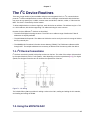
dsPIC
Elmer 166
An introduction to using the dsPIC
John J. McDonough, WB8RCR
Elmer 166
dsPIC Elmer 166
An introduction to using the dsPIC
Edition 1
Author
John J. McDonough, WB8RCR
[email protected]
The text of and illustrations in this document are licensed by John J. McDonough, WB8RCR under a
Creative Commons Attribution--Share Alike 3.0 Unported license ("CC-BY-SA"). An explanation of CC-BYSA is available at http://creativecommons.org/licenses/by-sa/3.0/. In accordance with CC-BY-SA, if you
distribute this document or an adaptation of it, you must provide the URL for the original version.
The 16-bit Microchip PIC parts are very powerful and significantly easier to use than their 8-bit
coounterparts. This book gives an introduction on how to use those parts, aimed specifically at the
hobbyist.
Preface
v
1. Overview
1.1. Overview of Microcontrollers ...............................................................................................
1.2. The dsPIC30F4011 ............................................................................................................
1.3. Building Programs .............................................................................................................
1
1
2
3
2. First Program - Blink an LED
5
2.1. Creating the project ........................................................................................................... 5
2.2. Editing and Compiling the Source ..................................................................................... 11
2.3. Running the Simulator ...................................................................................................... 14
2.4. Running the program in the dsPIC .................................................................................... 16
2.5. Debugging the program .................................................................................................... 17
2.6. Documenting the program ................................................................................................ 17
3. Configuration Registers
19
4. Timers
21
5. Interrupts
23
6. Liquid Crystal Displays
25
2
27
27
27
28
30
8. The I C Library
2
8.1. The I C Transaction .........................................................................................................
2
8.2. The I C Control Byte ........................................................................................................
2
8.3. Sending data to an I C device ..........................................................................................
2
8.4. Reading data from an I C device ......................................................................................
2
31
31
31
32
32
9. Building Libraries
33
10. Analog Inputs
35
11. Reading Switches
37
12. Pulse Width Modulation
39
13. Serial Output
41
14. Serial Input
43
15. Unusual Devices
45
A. Installing MPLAB-X
47
B. Setting up a project in MPLAB-X
51
C. The C
C.1.
C.2.
C.3.
55
55
56
56
56
57
7. The I C Device Routines
2
7.1. I C Device Connections ...................................................................................................
7.2. Using the MCP4726 DAC .................................................................................................
7.3. Using the MCP23008 I/O Expander ..................................................................................
7.4. Using the MB85RC16V FRAM ..........................................................................................
Language
Introduction .....................................................................................................................
Identifiers ........................................................................................................................
Types, Operators and Expressions ...................................................................................
C.3.1. Scalar types .........................................................................................................
C.3.2. Array and Pointer types ........................................................................................
iii
Elmer 166
C.4.
C.5.
C.6.
C.7.
C.3.3. Structure and Union types .....................................................................................
Control Flow ...................................................................................................................
Functions and Program Structure .....................................................................................
The C preprocessor .........................................................................................................
dsPIC-specific identifiers ..................................................................................................
59
59
59
59
59
D. The dsPIC-EL Board
61
E. Microchip PIC Families
63
F. Compiler Support Locations
65
G. Revision History
67
Bibliography
69
Index
71
iv
Preface
v
vi
Chapter 1.
Overview
1.1. Overview of Microcontrollers
1
A microcontroller is a microprocessor intended for embedded applications.
Microcontrollers differ from traditional microprocessors in a few key ways:
1. Microcontrollers generally are totally self-contained, requiring no external support other than power
and sometimes a clock source.
2. Microcontrollers generally include non-volatile program memory so that the program need not be read
from external media during startup. Most commonly, microcontrollers incorporate Flash memory for
program storage.
3. Microcontrollers are generally Harvard Architecture processors rather than traditional von Neumann
processors. The Harvard Architecture allows for different memory widths between the data and
program memory, and the separate busses allow data and program instructions to be fetched during
the same instruction cycle.
4. Embedded applications often require a high degree of detrminism. To support this, most
microcontrollers execute all or most instructions in the same number of clock cycles. In contrast,
microprocessors such as the Intel family may execute some instructions in just a few cycles, while
others take dozens.
5. Microcontrollers tend to use most of their pins for I/O. In contrast, microprocessors tend to use their
pins for data busses, multi-phase clocks, cache memory, and other, non-application purposes.
6. Microcontrollers frequently have a variety of available peripherals internal to the part. Serial ports, I2C
interfces, analog to digital converters and the like are common. Microprocessors tend to have a few
general putpose I/O pins, if that.
7. Micocontrollers typically have a number of power saving features, and often require very little power.
Compare a typical dsPIC, requiring about 150 milliwatts at full speed with a typical PC microprocessor
requiring 70 or more watts. And the dsPIC has features allowing it to reduce its power requirement to
the nanowatt range for some applications. In many embedded applications the microcontroller current
is less than the internal leakage current of the battery.
8. Microcontrollers tend to be inexpensive, ranging from around a quarter to perhaps ten dollars. Refer to
Appendix E, Microchip PIC Families for examples. Microprocessor prices range from a few dollars to
several hundreds of dollars. As of this writing, the suggested price for Intel's i7-3940XM is $1096.
1
embedded system n. A combination of computer hardware and software, and perhaps additional mechanical or other parts,
designed to perform a dedicated function. In some cases, embedded systems are part of a larger system or product, as in the case
of an antilock braking system in a car.[Barr]
1
Chapter 1. Overview
Figure 1.1. dsPIC Overview
Table 1.1. The dsPIC30F Family
Minimum
Maximum
dsPIC30F4011
Program Memory
6K
144K
48K
Data Memory
256
8192
2048
EEPROM Memory
0
4096
1024
Pin Count
18
80
40
UART
1
2
2
SPI
1
2
1
I2C
1
2
1
CAN
0
2
1
Comparators
0
4
4
A/D Channels
6
18
9
Quadrature Encoder Inputs
0
1
1
Timers
2
5
5
Volume Price
$2.23
$7.25
$4.02
Quantity One Price
$3.09
$11.94
$5.70
Prices are from Microchip Direct for quantity one, from the Product Selector for volume prices
1.2. The dsPIC30F4011
Figure 1.2. dsPIC30F4011 Ports
2
Building Programs
1.3. Building Programs
Figure 1.3. Program Building Process
3
4
Chapter 2.
First Program - Blink an LED
The first program will be the classic "flash an LED" program. This provides a simple look into programming
the PIC without any unnecessary complexities. Well, maybe without too many complexities.
2.1. Creating the project
Everything done within MPLAB-X is done within the context of a project, so the first order of business is
to set up a project.
Begin by launching MPLAB-X, either by double-clicking the desktop icon or selecting the MPLAB-X IDE
from the menu.
Figure 2.1. MPLAB-X desktop icon
5
Chapter 2. First Program - Blink an LED
The first time MPLAB-X is launched it will display the MPLAB-X "Start Page". The start page has many
interesting links worth pursuing at a later date.
Figure 2.2. MPLAB-X Opening Screen
On successive launches, MPLAB-X will open with the same project that was opened when it was closed.
To create a new project, click the new project button at the left of the toolbar, or click "Create New
Project" under "Dive In" on the start page.
Figure 2.3. New project button
This will launch the new project wizard.
6
Creating the project
The first panel chooses the overall type of project. Almost always the default selections of "Microchip
Embedded" and "Standalone Project" are the desired choices.
Figure 2.4. Select type of project
The next panel selects the specific processor. For this lesson, choose the "16-bit DSCs (dsPIC30)"
Family and within that family, the "dsPIC30F4011" Device.
Figure 2.5. Select processor
7
Chapter 2. First Program - Blink an LED
The next selection is for the hardware programming or debugging tool. In this exercise, the simulator will
be used to get a detailed view of what the program is doing before actually downloading it into the dsPIC,
so select "Simulator".
Figure 2.6. Select hardware tool
In the next panel, the compiler is selected. Choose "XC16". (The version and path to the compiler may
be different.)
Figure 2.7. Select Compiler
8
Creating the project
In the final project wizard panel, enter a name for the project.
Figure 2.8. Assign project name
9
Chapter 2. First Program - Blink an LED
Two panes will open on the left of the main MPLAB-X window. The upper pane (labeled Projects) will
list the various possible components of a project, while the lower will show an overall view of the project
(called the "Dashboard"). In addition, a "Tasks" pane will open beneath the Start Page.
Figure 2.9. MPLAB-X Empty Project
Note the in MPLAB-X it is possible to place almost any pane in almost any position, and MPLAB-X
remembers previous settings, so if the application had been used previously, the various panes may be in
different locations or have different contents.
10
Editing and Compiling the Source
2.2. Editing and Compiling the Source
Once a project has been created, the next order of business is to create a file in the project to contain
the code. Within the upper left (Project) pane, right-click on "Source Files", roll over "New" and select
"Empty File ...".
Figure 2.10. Add a new file to the project
11
Chapter 2. First Program - Blink an LED
A dialog will open allowing you to provide a name for the project. Be certain the filename you choose ends
in .c. At this point it is worth considering your conventions for naming source files. It is the C tradition
to name the mainline of a C program main.c. However, there will be a lot of main.c's, so it could be
preferable to name the mainline source the same as the name of the project. If you really like to type, you
may prefer to combine both, as shown below.
Figure 2.11. Name the new file
One problem with having very long names is that they take space in the project pane. If you have a lower
resolution screen, you may prefer to leave as much space as possible for the rightmost pane, making your
left panes smaller. it can be quite annoying if most of the filenames are hidden.
#include <xc.h>
int main()
{
TRISDbits.TRISD1 = 0;
while( 1 )
{
LATDbits.LATD1 = 0;
LATDbits.LATD1 = 1;
}
}
Refer to Table F.1, “Include Files” for a list of include file locations known to the compiler.
12
Editing and Compiling the Source
Figure 2.12. Add code
Figure 2.13. Compile button
13
Chapter 2. First Program - Blink an LED
2.3. Running the Simulator
Figure 2.14. Set a breakpoint
Figure 2.15. Debug program button
Figure 2.16. Debugging controls
14
Running the Simulator
Figure 2.17. Second toolbar row
Figure 2.18. Open the variables window
15
Chapter 2. First Program - Blink an LED
Figure 2.19. Create a watch expression
Figure 2.20. Select the variable to watch
Figure 2.21. Observe the value change
2.4. Running the program in the dsPIC
16
Debugging the program
Figure 2.22. Download program button
2.5. Debugging the program
2.6. Documenting the program
/* Exercise01_main.c - Blink an LED */
#include <xc.h>
int main()
{
/* Set the LED pin to be an output */
TRISDbits.TRISD1 = 0;
/* Keep doing this a very long time */
while( 1 )
{
/* Turn the LED on */
LATDbits.LATD1 = 0;
/* Turn the LED off */
LATDbits.LATD1 = 1;
}
}
Figure 2.23. MPLAB-X
17
Chapter 2. First Program - Blink an LED
// Ex02.c - Blink an LED
#include <xc.h>
int main (void)
{
_TRISD3 = 0;
while (1)
{
_LATD3 = 1;
_LATD3 = 0;
}
}
Provides definitions for the dsPIC registers.
Sets the pin connected to the LED to be an output.
It will take some time before one becomes zero.
Turns off the LED.
Turns on the LED.
18
Chapter 3.
Configuration Registers
// Configuration fuses
_FOSC (XT)
_FWDT (WDT_OFF)
_FBORPOR (PWRT_16 & BORV27 & MCLR_EN)
_FGS (GWRP_OFF & CODE_PROT_OFF)
//
//
//
//
7.3728 xtal / 4 = 1.8432 MIPS
Watchdog timer off
Brownout off, powerup 16ms
No code protection
19
20
Chapter 4.
Timers
// Set up timer
// 7.3728 MHz * 16xPLL /Fosc/4 / 256 prescaler / 57600 counter
// timer should fire twice per second. Since the LED
// will toggle once per interrupt, the LED should come on
// once per second for a half second.
TMR2 = 0;
// Clear timer 2
PR2 = 57600;
// Timer 2 counter to 576000
T2CON = 0x8030;
// Fosc/4, 1:256 prescale, start TMR2
if ( IFS0bits.T2IF )
{
IFS0bits.T2IF = 0;
LATD ^= 0x0002;
}
21
22
Chapter 5.
Interrupts
// Set up timer
// 7.3728 MHz * 16xPLL /Fosc/4 / 256 prescaler / 57600 counter
// timer should fire twice per second. Since the LED
// will toggle once per interrupt, the LED should come on
// once per second for a half second.
TMR2 = 0;
// Clear timer 2
PR2 = 57600;
// Timer 2 counter to 576000
T2CON = 0x8030;
// Fosc/4, 1:256 prescale, start TMR2
IEC0bits.T2IE = 1;
// Enable timer interrupt
// Timer 2 interrupt routine - toggle the red (bottom) LED
// each time the interrupt occurs.
void __attribute__((__interrupt__, auto_psv)) _T2Interrupt( void )
{
IFS0bits.T2IF = 0;
// Clear timer interrupt flag
// This is always the first order of
// business in an interrupt routine
LATD ^= 0x0002;
// Toggle red LED
}
23
24
Chapter 6.
Liquid Crystal Displays
25
26
Chapter 7.
2
The I C Device Routines
2
There are a large number of parts available using the Inter-Integrated Circuit, or I C, communications
2
protocol. I C allows multiple devices to share a two line bus. Although communication with the devices
may occur at any speed up to 3.4 Mb/s, common rates are 100 kb/s, 400 kb/s, 1 Mb/s, 1.7 Mb/s and 3.4
Mb/s. The clock is controlled by the bus master.
To allow multiple devices to share a single bus, each device has an address. The address may be a 7 bit
or a 10 bit address, with devices supporting 7 bit addresses being far more common.
2
Routines for three different I C devices are described.
• The MCP4726 Digital to Analog converter. The 4726 has an address range of 0x60 to 0x67 Not all
addresses are equally available.
• The MCP23008 I/O Expander. The address of this device can be set by the user in the range of 0x20 to
0x27 by external pins.
• The MB85RC16V Ferroelectric Random Access Memory (FRAM). The FRAM uses addresses 0x50
through 0x57. The multiple addresses are necessary to address all of the memory within the device.
2
7.1. I C Device Connections
2
I C devices are wired in parallel, with pull-up resistors on the bus. The value of the resistor is determined
by the speed desired (>2K for 5 volt systems, <20K depending on the bus capacitance[PHI1]). For higher
speeds, the designer must take care to minimize the capacitance of the bus.
Figure 7.1. I2C Wiring
The included library i2c.a provides for writing a value to the DAC, reading and writing the I/O extender,
and reading and writing the FRAM.
7.2. Using the MCP4726 DAC
27
2
Chapter 7. The I C Device Routines
Since the DAC is a relatively simple device, using the routine is quite straightforward. Although the
MCP4726 includes a number of other features like RAM & EEPROM[MCP6], what the designer generally
wants from a DAC is to output a specific voltage. The MCP4726write() function provides that capability.
2
In order to use any of the I C routines, the user must include i2c.h and the header file for the particular
device, in this case, MCP4726.h.
#include "../include/i2c.h"
#include "../include/MCP4726.h"
2
Before using any of the device routines, the I C peripheral must be initialized. The function InitI2C()
performs this initialization. The function sets the peripheral to master, establishes the baud rate, and sets
2
reasonable defaults for a number of I C parameters.
InitI2C();
This need be done only once.
All that remains, then, is to write the data to the DAC. The MCP4726write() function takes two
parameters, the address of the device and the value to be written. The MCP4726 is a 12-bit DAC, so the
value is a 12 bit value.
MCP4726write( 0x60, nValue );
Typically, the developer will want to write some fraction of "full scale" to the DAC, but it is possible that
a specific voltage is desired. When presented with a value of 4095, the DAC will output the reference
voltage, typically 5V. With a zero the device will output zero volts. Thus, if a 2048 is entered, the DAC will
deliver 2.5 volts. If speed is not a concern, then, the code might look something like:
/* Voltage fVolts from previous calculation */
fDACvalue = (fVolts / 5.0) * 4095.0;
nDACvalue = (int)fDACvalue;
MCP4726write( 0x60, nDACvalue );
or more directly:
MCP4726write( DACADDR, (int)((fVolts / 5.0) * 4095.0) );
The floating point library is large and slow, so the programmer may prefer to stick with integers. In this
case, it is important to avoid overflow in the calculations. While the DAC value may easily fit in an integer,
an integer voltage would have low resolution, and multiplying millivolts by 4095 will often result in an
integer overflow. The solution is to force the compiler to use long values for the intermediate calculations:
/* Voltage nMillivolts from previous calculation */
nDACvalue = (int)( (long)nMillivolts * 4095L / 5000L );
MCP4726write( 0x60, nDACvalue );
7.3. Using the MCP23008 I/O Expander
28
Using the MCP23008 I/O Expander
The MCP23008 I/O Expander is a more complex device[MCP5]. It has eight I/O pins, each of which may
be configured as an input or an output. This makes it useful when a large number of I/O devices are
2
required and speed is not an issue (I C can only send thousands of commands a second, compared to
millions of changes or tests per second possible directly to a port). Since the possible addresses allow for
2
eight devices, a total of 64 digital I/O pins may be supported on a single I C bus.
The device has 11 registers that may be read or written. In most cases, only three of these registers
are of interest; the IODIR register, comparable to the TRIS registers in the PIC, the GPIO register,
comparable to the PORT registers in the PIC, and the OLAT register, comparable to the PIC LAT registers.
The remaining registers allow for setting weak pull-ups on inputs, setting default states for outputs, and
allowing for interrupt on change.
The include file, MCP23008.h includes definitions for all the registers as well as function prototypes for
the two provided functions, MCP23008writeRegister() and MCP23008readRegister(). As with all
2
I C functions, i2c.h must also be included so that InitI2C() may be called:
#include "../include/i2c.h"
#include "../include/MCP23008.h"
If only input is required, calling MCP23008readRegister() fetches the current state of the pins:
InitI2C();
/* Get the current state of the I/O expander's pins */
ucPortState = MCP23008readRegister( 0x20, MCP23008_GPIO );
The I/O extender defaults to input mode on power up.
For writing, the I/O direction register must first be set to make the desired pins be outputs. Like the PIC, a
0 bit sets the pin to be an output, so to make all pins outputs:
MCP23008writeRegister( 0X20, MCP23008_IODIR, 0x00 );
Consider a case with a button on pin 1, and an LED on pin 4. To light the LED whenever the button was
pressed. Our code might look something like:
unsigned char ucPortValue;
/* Initialize I2C and the MCP23008 */
InitI2C();
MCP23008writeRegister( 0X20, MCP23008_IODIR, 0xef );
while ( 1 )
{
/* Get the state of the button */
ucPortValue = MCP23008readRegister( 0x20, MCP23008_GPIO );
/* Is the button pressed? */
if ( ucPortValue & 0x02 )
/* Yes, turn on the LED */
MCP23008writeRegister( 0X20, MCP23008_OLAT, 0x10 );
else
/* No, turn off the LED */
MCP23008writeRegister( 0X20, MCP23008_OLAT, 0x00 );
}
29
2
Chapter 7. The I C Device Routines
7.4. Using the MB85RC16V FRAM
The MB85RC16V Ferroelectric Random Access Memory[FUJ1] is a 2Kx8 non-volatile memory chip. It is
useful in cases where the microcontroller does not include enough EEPROM for the application. Many of
the 16-bit families do not include any EEPROM, so this can be useful in cases where other families are
selected. The part can be used in both 3.3 and 5 volt designs.
The data retention for the MB85RC16V is only 10 years, so that is not an advantage over the
10
dsPIC30F4011's EEPROM retention of 100 years. However, a single cell can be written 10 times,
considerably more than the EEPROM's one million writes, so the part might be considered for applications
where many rewrites are expected.
The library contains two functions for using the FRAM, MB85RC16VwriteByte() and
MB85RC16VreadByte(). In addition to the base address of the device (which must always be 0x50), the
function takes an 11 bit address.
#include "../include/i2c.h"
#include "../include/MB85RC16V.h"
.
.
.
/* Initialize the I2C peripheral */
InitI2C();
/* Read a value from the FRAM */
ucMemValue = MB85RC16VreadByte( 0x50, nAddress );
/* Write a value to the FRAM */
MB85RC16VwriteByte( 0x50, nAddress, ucMemValue );
30
Chapter 8.
2
The I C Library
In addition to the device routines, the library includes a complete set of low level I2C routines for devices
2
2
with seven bit I C addresses. Almost all I C devices may be supported with these routines.
2
Table 8.1. Low-level I C functions
Operation
Function
2
Initialize the I C peripheral
void InitI2C( void )
2
Start an I C transaction
unsigned int StartI2C( void )
2
Restart an I C transaction
unsigned int RestartI2C( void )
2
Terminate an I C transaction
unsigned int StopI2C( void )
2
Write a byte to an I C device
void WriteI2C( unsigned char )
2
Read a byte from an I C device
unsigned char getI2C( void )
2
Check that the I C bus is idle
void IdleI2C( void )
2
Send an acknowledgement to an I C device
2
Set a non-acknowledge (NAK) to an I C device
2
Test the acknowledge status of the I C bus
void AckI2C( void )
void NotAckI2C( void )
unsigned int ACKstatusI2C( void )
2
8.1. The I C Transaction
2
Operations on the I C bus are handled as transactions[PHI1]. The transaction must be started, then
operations may take place, and then the transaction must be stopped before another transaction may take
place.
In the case of a microcontroller communicating with a set of peripheral ICs, the microcontroller is the bus
master, and is responsible for starting and stopping transactions. The slave sends an acknowledge bit at
the end of each byte sent by the master. In the case of the dsPIC, handling the acknowledge bit is dealt
with by the hardware.
2
8.2. The I C Control Byte
The first byte sent in any transaction is the control byte. The control byte contains the target device
address in the high seven bits. The low bit is cleared if the master intends to write data to the slave, and
set if the master expects the slave to send data. However, a set read/write bit may only be sent following
2
an I C restart.
Thus, a function to communicate with a device will calculate the control byte by shifting the address one
bit to the left clearing the low bit:
ucControlByte = ucDeviceAddress<<1;
31
2
Chapter 8. The I C Library
2
8.3. Sending data to an I C device
Thus to send data to a device the sequence is: starting the transaction, sending the control byte, sending
the data, and stopping the transaction. Once again, it is important to study the device datasheet. Many
devices expect to receive multiple bytes of data in each transaction.
As an example, consider the MCP4726 DAC[MCP6]. This is a 12 bit DAC. Since only 8 bits may be sent
to the device at a time, the data must be broken up into two transmissions, the first sending the high four
bits and the second, the lower eight:
/* Write condition is a zero bit so the control byte is formed
* merely by shifting the address left one bit */
ucControlByte = ucDevice<<1;
/* Break value into two bytes */
ucByteH = uValue >> 8;
ucByteL = uValue & 0xff;
StartI2C();
/* Start I2C transaction
WriteI2C(ucControlByte); /* Address of MCP4726 | write
WriteI2C(ucByteH); /* high 4 bits of value
WriteI2C(ucByteL); /* Low 8 bits of value
StopI2C();
/* Stop the transaction
*/
*/
*/
*/
*/
2
8.4. Reading data from an I C device
Reading data is a bit more complex. The master must send the control byte as usual, and often,
must send the slave some indication of what information is needed. The master must then restart the
transaction and send the control byte, this time with the read bit set. The master (dsPIC) may then read
the data from the device. The data must then be acknowledged or not acknowledged by the master before
stopping the transaction. In many cases, the default is to not acknowledge (NAK) the data, because an
acknowledge (ACK) is a signal to the device to send more data! Again, it is critically important to become
familiar with the device datasheet.
Consider the MCP23008 I/O extender[MCP5]. The master must start the transaction, send the control
byte, then send the register whose contents are desired. Then the transaction is restarted, the data
fetched from the slave, and a NAK sent. Finally the transaction may be stopped. Should the master have
sent an ACK, the 23008 would then send the contents of the next register:
/* Write condition is a zero bit so the control byte is formed
* merely by shifting the address left one bit */
ucControlByte = ucDevice<<1;
StartI2C();
/*
WriteI2C( ucControlByte ); /*
WriteI2C( ucRegister );
/*
RestartI2C();
/*
WriteI2C( ucControlByte+1 );/*
ucResult = getI2C();
/*
NotAckI2C();
/*
StopI2C();
/*
32
Start I2C transaction
Send bus Address
Address of desired register
Restart so can send read
Send bus address with read bit
Get answer from MCP23008
NAK result to stop answers
Send stop on bus
*/
*/
*/
*/
*/
*/
*/
*/
Chapter 9.
Building Libraries
33
34
Chapter 10.
Analog Inputs
// Initialize ADC
/* set port configuration here */
ADPCFGbits.PCFG8 = 0; // ensure AN8/RB8 is analog
/* set channel scanning here, auto sampling and convert,
with default read-format mode */
ADCON1 = 0x00E4;
/* No channel scan for CH0+, Use MUX A,
SMPI = 1 per interrupt, Vref = AVdd/AVss */
ADCON2 = 0x0000;
/* Set Samples and bit conversion time */
ADCON3 = 0x1f3f; //(as slow as possible)
/* set channel scanning here for AN8 */
ADCSSLbits.CSSL8 = 1;
/* channel select A3 */
ADCHSbits.CH0SA3 = 1;
/* reset ADC interrupt flag */
IFS0bits.ADIF = 0;
/* enable ADC interrupts */
IEC0bits.ADIE = 1;
/* turn on ADC module */
ADCON1bits.ADON = 1;
//! ADC Interrupt Service Routine
/*!
* Whenever an analog value is available, thie routine will:
* \li Clear the interrupt flag
* \li Grab the analog value and store it in potValue
* \li Increment analogRead
*
*/
void __attribute__ ((__interrupt__, auto_psv))
_ADCInterrupt (void)
{
IFS0bits.ADIF = 0; // Clear A/D interrupt flag
potValue = ADCBUF0; // Save the potentiometer value
analogRead++; // Remember it has been read
}
35
36
Chapter 11.
Reading Switches
37
38
Chapter 12.
Pulse Width Modulation
// Set up timer 2 for PWM
TMR2 = 0;
// Clear timer 2
PR2 = 1000;
// Timer 2 counter to 1000
T2CON = 0x8010;
// Fosc/4, 1:4 prescale, start TMR2
// Set up PWM on OC2 (RD1)
OC2RS = 1024;
// PWM 2 duty cycle
OC2R = 0;
//
OC2CON = 0x6;
// Set OC2 to PWM mode, timer 2
// Loop through 360 degrees
for ( theta=0.0; theta<TWOPI; theta += 0.05 )
{
// Set the brightness of the LED based on the sine
// of the angle.
OC2RS = (int)(512.0-512.0*sin(theta+PIOVER4));
// Slow it down
for ( i=0; i<50000; i++ )
;
}
39
40
Chapter 13.
Serial Output
41
42
Chapter 14.
Serial Input
43
44
Chapter 15.
Unusual Devices
45
46
Appendix A. Installing MPLAB-X
Figure A.1. Locate the Development Tools
Figure A.2. Select Tools to Download
47
Appendix A. Installing MPLAB-X
Figure A.3. Open Downloaded Installer
Figure A.4. Allow it to run
48
Figure A.5. Install Wizard
Figure A.6. XC Already Downloaded
49
50
Appendix B. Setting up a project in
MPLAB-X
Figure B.1. MPLAB-X Desktop Icon
Figure B.2. New Project Button
Figure B.3. MPLAB-X Project Type
51
Appendix B. Setting up a project in MPLAB-X
Figure B.4. Selecting the Processor
Figure B.5. Select Programmer/Debugger
Figure B.6. Selecting the Toolchain
Figure B.7. Name the Project
52
Figure B.8. Create a Source File
Figure B.9. Name the Source File
53
54
Appendix C. The C Language
C.1. Introduction
This appendix will not turn you into an expert C programmer, nor is it even a decent tutorial. it will,
however, give you a little bit to get started with.
C is actually quite a simple language. There are only a handful of keywords and precious few rules.
Indeed, this lack of rules does tend to be difficult for folks coming from older languages such as Basic or
FORTRAN.
1
In this course, we won't be making use of a lot of elaborate code. Embedded applications by their nature
tend to be simple. Even someone unfamiliar with programming should have little problem following the
code.
There are a few things about C that take a little getting used to. The following few paragraphs outline the
most obvious:
All whitespace is created equal
In C, a space, tab and newline are all called whitespace. Any combination of these characters is also
whitespace. Thus, a tab is the same as a space, as is three newlines followed by a space, or fourteen
tabs. They are all equivalent to a single space. One result is that the end of a line has nothing whatsoever
to do with the end of a statement. Statements may cross line boundaries with impunity. The exception is
a string literal. String literals are not allowed to cross line boundaries. However, there are ways of writing
newlines in literal strings.
Everything is case sensitive
Identifiers, keywords, anything C cares about is case sensitive. Thus, A has nothing to do with a, if is a
keyword while IF is not.
C will not try to out-guess you
In many languages, the compiler will prevent you from doing really stupid things. Not so in C. If you
wrote it, the compiler assumes you meant it, no matter how silly it may be. One fairly obvious place
where people can go wrong is in arrays. If you declare an array of, say, ten integers, and then access
the hundredth element of that array, C will assume that is exactly what you meant, and merrily return
whatever is in memory where the hundredth element of that array would have been, had it actually been
1
The Embedded Systems Glossary[Barr] provides the following definition for an embedded system, focusing largely on the
application: "embedded system n. A combination of computer hardware and software, and perhaps additional mechanical or other
parts, designed to perform a dedicated function. In some cases, embedded systems are part of a larger system or product, as in the
case of an antilock braking system in a car."
Wikipedia[WP1] focuses more on the hardware: "An embedded system is a computer system designed for specific control functions
within a larger system, often with real-time computing constraints. It is embedded as part of a complete device often including
hardware and mechanical parts. By contrast, a general-purpose computer, such as a personal computer (PC), is designed to be
flexible and to meet a wide range of end-user needs. Embedded systems control many devices in common use today."
55
Appendix C. The C Language
that long. Of course, this can have very unfortunate side effects. But C has great faith that you knew what
you were doing when you wrote that.
C.2. Identifiers
Variables and functions in C are assigned names called identifiers. ANSI C sets some minimum
requirements for identifiers, but also allows some implementation flexibility. As a general rule, XC16
makes maximum use of that flexibility.
An identifier is a sequence of letters and/or digits which must begin with a letter. The underbar (_)
character counts as a letter.[KandR] Identifiers may be of any length, and all characters are significant.
[MCP1] (The ANSI standard requires at least the first 31 characters be significant). Identifiers are case
sensitive.
C.3. Types, Operators and Expressions
C.3.1. Scalar types
There are two general categories of values within C; integer and floating point. Within those categories are
a number of different types. What those types actually mean is somewhat implementation dependent. For
example, int is an integer of the natural size for the target processor. long is an integer the same size
as int or longer, short the same size as int or shorter.
For XC16 the following are the integer types:[MCP1]
Table C.1. Integer Types
Type
Bits
Min
Max
char
8
-128
127
signed char
8
-128
127
unsigned char
8
0
255
short
16
-32768
32767
signed short
16
-32768
32767
unsigned short
16
0
65536
int
16
-32768
32767
signed int
16
-32768
32767
unsigned int
16
0
65535
long
32
-2147483648
2147483647
signed long
32
-2147483648
2147483647
unsigned long
32
0
4294967296
long long
64
-9223372036854775808
9223372036854775807
signed long long
64
-9223372036854775808
9223372036854775807
56
Array and Pointer types
Type
unsigned long long
Bits
64
Min
Max
0
18446744073709551615
The following are the floating point types:
Table C.2. Floating Point Types
Type
Bits
Exponent Min
Exponent Max
float
32
-126
127
double
32
-126
127
long double
64
-1022
1023
A number containing no decimal and not beginning with a zero is assumed to be a decimal constant of
the type int. In many contexts, however, the compiler may recognize that some other type was intended
such as unsigned or long.
A number beginning with a 0 is taken as an octal constant. In this case the digits 8 and 9 are not
permitted. A number beginning with 0x is taken as a hexadecimal constant. In this case the additional
characters a A b B c C d D e E f F are permitted.
A binary constant may be specified as a string of 1 and 0 characters preceded by 0b.
A constant may be specified as long by suffixing it with l or L. A constant may be specified as
unsigned by suffixing it with u or U.
Constants may also be represented as their ASCII equivalents when surrounded by single quotes. For
example, 0x31, 49 and '1' represent the same value.
There are a number of special strings called escape sequences that may be used to represent
special characters in ASCII constants:
• \0 - 0, the NULL character
• \a - 7, the bell character
• \b - 8, the backspace character (not the same as the backspace key)
• \t - 9, the tab character
• \n - 10, the newline character
• \v - 11, the vertical tab character
• \f - 12, the formfeed character
• \r - 13, the carriage return character
• \0 followed by octal digits - the octal value of a character
• \0x followed by hex digits - the hexadecimal value of a character
C.3.2. Array and Pointer types
Pointer types are very important in C, perhaps more important than in many languages. A pointer is a
variable that contains the address of some object.
C also allows the specification of arrays of any type, even other aggregate types, including arrays. An
issue that can be challenging at first is that the name of an array is a pointer to an array.
57
Appendix C. The C Language
A pointer is specified by prefixing the name with an * in the declaration. Thus, int *n; specifies a
pointer, n, which points to an integer.
A pointer declaration does not allocate memory
The declaration of a pointer only allocates the pointer. It does not allocate any space for the thing that
might be pointed to.
An array is declared by suffixing the name with the ordinality surrounded by square brackets ([]).
Thus, unsigned long g[10]; would declare an array of 10 elements of unsigned long named g
and allocate the necessary memory. Array elements are numbered starting at zero, thus, in the above
example, valid elements are numbered zero through nine.
Since a pointer and an array name are the same, and may be used interchangably, incrementing a pointer
or an array name increments it by the size of the thing pointed to. The same holds for any arithmetic.
Thus, in the code below:
int array[10];
int *pointer;
int a;
pointer = array;
a = array[5];
pointer = pointer + 5;
a = *pointer;
a = array[5]; and a = *pointer; have the same effect.
Similarly, an "element" of a pointer may be specified. For example:
int array[10];
int *pointer;
int a;
pointer = array;
a = array[5];
a = pointer[5];
Character strings in C are simply arrays of char. The compiler treats these arrays no differently than other
arrays, except that there is a convenient way of expressing a string literal; it is simply a string of characters
surrounded by double quotes.
By convention, a character string is terminated by a NULL character. The compiler does not enforce
this, except that the compiler does provide the terminating NULL for a literal string. Most library routines,
however, count on this, so it is generally important to be sure the terminating null is preserved when
strings are manipulated.
When a character string is declared, it is important to include space to allow for the terminating NULL.
Thus char myString[10]; provides space for a nine character string plus the terminating NULL.
58
Structure and Union types
C.3.3. Structure and Union types
struct
{
int PointID;
double Temperature;
double ScalingFactor;
double Offset;
char Name[32];
} TemperaturePoint[10];
union
{
long a;
struct
{
int b1;
int b2;
} b;
} longintunion;
C.4. Control Flow
C.5. Functions and Program Structure
C.6. The C preprocessor
C.7. dsPIC-specific identifiers
59
60
Appendix D. The dsPIC-EL Board
61
62
Appendix E. Microchip PIC Families
Figure E.1. PIC Families
63
64
Appendix F. Compiler Support Locations
The following directories are all relative to the compiler install directory which is typically something like
(some directory)/microchip/xc16/(version)/. The following tables show only locations relevant to the
dsPIC30F family of processors. There are additional directories for other processors. Your installation may
use \ instead of /.
Table F.1. Include Files
Directory
Contents
include
Contains header files associated with the standard
(non-PIC specific) C libraries
support/dsPIC30F
Contains definitions for the registers specific to the
various models of dsPIC30F chips
support/peripheral_30F_24H_33F
Contains detailed definitions of the various
peripherals
support/generic
Contains definitions applicable to all 16 bit PICs
Table F.2. Linker Script Files
Directory
Contents
support/gld/dsPIC30F
Linker script files for each of the dsPIC30F
processors
Table F.3. Library Files
Directory
Contents
lib
Libraries common to all 16-bit microcontrollers and
DSCs
lib/dsPIC30F
Libraries specific to the dsPIC30F family of Digital
Signal Controllers
65
66
Appendix G. Revision History
Revision 0-3
Sun Jan 20 2013
Earl corrections
John McDonough [email protected]
Revision 0-2
Wed Jan 9 2013
Add chapters on I2C
John McDonough [email protected]
Revision 0-1
Initial prose
John McDonough [email protected]
Fri Oct 26 2012
Revision 0-0
Tue Sep 4 2012
Initial creation of book by publican
John McDonough [email protected]
67
68
Bibliography
[Barr] Michael Barr. Copyright © 2012 Barr Group. Barr Group . Embedded Systems Glossary. E.
[FUJ1] Sales Promotion Department, Fujitsu Semiconductor Limited. Copyright © 2011 FUJITSU
2
SEMICONDUCTOR LIMITED. Fujitsu Semiconductor . Memory FRAM. 16 K (2 K x 8) Bit I C
MB85RC16V. DS501-00010-2v0-E.
[KandR] Brian Kernighan and Dennis Ritchie. Copyright © 1988, 1978 Bell Telephone Laboratories, Inc.
Prentice Hall P T R . 0-13-110370-9. The C Programming Language.
[MCP1] Microchip. Copyright © 2009 Microchip Technology, Inc. Microchip Technology, Inc . MPLAB C
Compiler for PIC24 MCUs and dsPIC DSCs User's Guide. DS51284J.
[MCP2] Microchip. Copyright © 2010 Microchip Technology, Inc. Microchip Technology, Inc . 16-Bit
Language Tools Libraries. DS51456G.
[MCP3] Microchip. Copyright © 2006 Microchip Technology, Inc. Microchip Technology, Inc . dsPIC30F
Family Reference Manual. DS70046E.
[MCP4] Microchip. Copyright © 2004 Microchip Technology, Inc. Microchip Technology, Inc .
dsPIC30F4011/4012 Data Sheet. High Performance Digital Signal Controllers. DS70135B.
[MCP5] Microchip. Copyright © 2007 Microchip Technology, Inc. Microchip Technology, Inc . MCP23008/
MCP23S08. 8-Bit I/O Expander with Serial Interface. DS21919E.
[MCP6] Microchip. Copyright © 2011-2012 Microchip Technology, Inc. Microchip Technology, Inc .
MCP4706/4716/4726. 8-/10-/12-Bit Voltage Output Digital-to-Analog Converter with EEPROM and
2
I C™ Interface . DS22272C.
2
[PHI1] Phillips Semiconductor. Phillips Semiconductor . The I C Bus Specification. Version 2.1 January
2000. 9398 393 40011.
[WP1] various. The Wikimedia Foundation, Inc. . Wikipedia. Embedded_system.
69
70
Index
F
AckI2C, 31
ACKstatusI2C, 31
ANSI C, 56
Array, 55
float, 57
Floating point, 28
Formfeed character
in character literals, 57
FORTRAN, 55
FRAM
MB85RC16V, 30
B
G
Backspace character
in character literals, 57
Basic, 55
Bell character
in character literals, 57
Brownout protection
configuration setting, 19
getI2C, 31, 32
GPIO
MCP23008 register, 29, 29
A
C
C, 55
ANSI, 56
Carriage return character
in character literals, 57
Case Sensitivity, 55, 56
char, 56
Code protection
configuration setting, 19
Compiler
in New Project wizard, 8
Constant, 57
binary, 57
character, 57
decimal, 57
long, 57
unsigned, 57
Control byte
i2C, 31, 32, 32
D
DAC
MCP4726, 27, 32
Dashboard, 10
double, 57
E
Embedded
Project type, 7
Escape sequences, 57
H
Hardware tool
in New Project wizard, 8
Hexadecimal value
in character literals, 57
I
I/O Expander
MCP23008, 28, 32
I2C, 27
Identifiers, 56
IdleI2C, 31
InitI2C, 28, 29, 30, 31
int, 56
IODIR
MCP23008 register, 29, 29
L
Launching MPLAB-X, 5
Literal, 57
binary, 57
character, 57
decimal, 57
long, 57
unsigned, 57
long, 56
long double, 57
long long, 56
M
MB85RC16V, 30
MB85RC16VreadByte, 30
MB85RC16VwriteByte, 30
MCP23008, 28, 32
MCP23008readRegister, 29
71
Index
MCP23008writeRegister, 29
MCP4726, 27, 32
MCP4726write, 28
MPLAB-X
icon, 5
launching, 5
New project, 6
New project wizard, 6
Start page, 6
MPLAB-X project, 5
N
New Project, 6
Newline character
in character literals, 57
NotAckI2C, 31, 32
NULL character
in character literals, 57
O
Octal value
in character literals, 57
OLAT
MCP23008 register, 29, 29
Oscillator
configuration setting, 19
P
Power up timer
configuration setting, 19
Processor
in New Project wizard, 7
Project
in MPLAB-X, 5
Project type
in New Project wizard, 7
Projects pane, 10
R
RAM
Ferromagnetic, 30
Read bit
i2C, 32
RestartI2C, 31, 32
S
short, 56
signed, 56
Source file
72
creating, 11
Source Files
in Projects pane, 11
Standalone project
Project type, 7
Start Page, 6
StartI2C, 31, 32, 32
StopI2C, 31, 32, 32
T
Tab character
in character literals, 57
Transaction
I2C, 31
Types
Array, 57
floating point, 57
integer, 56
Pointer, 57
Scalar, 56
Structure, 59
Union, 59
U
unsigned, 56
V
Vertical tab character
in character literals, 57
W
Watchdog timer
configuration setting, 19
Whitespace
in C, 55
WriteI2C, 31, 32, 32
X
XC16, 8, 56