1
1ST PRINTING
JULY 99
TM
WORLD SERIES ’99
OWNER’S MANUAL
SEGA ENTERPRISES, INC. USA
MANUAL NO. 999-0813
Warranty
Your new Sega Product is covered for a period of 90 days from the date of shipment. This certifies
that the Printed Circuit Boards, Power Supplies and Monitor are to be free of defects in workmanship or materials under normal operating conditions. This also certifies that all Interactive Control
Assemblies are to be free from defects in workmanship and materials under normal operating conditions. No other product in this machine is hereby covered.
Sellers sole liability in the event a warranted part described above fails shall be, at its option, to
replace or repair the defective part during the warranty period. For Warranty claims, contact your
Sega Distributor.
Should the Seller determine, by inspection that the product was caused by Accident, Misuse, Neglect, Alteration, Improper Repair, Installation or Testing, the warranty offered will be null and void.
Under no circumstances is the Seller responsible for any loss of profits, loss of use, or other damages.
This shall be the exclusive written Warranty of the original purchaser expressed in lieu of all other
warranties expressed or implied. Under no circumstance shall it extend beyond the period of time
listed above.
TABLE OF CONTENTS
INTRODUCTION OF THE OWNERS MANUAL
GENERAL PRECAUTIONS
1. PRECAUTIONS TO BE HEEDED FOR OPERATION
2. NAME OF PARTS
3. ACCESSORIES
4. ASSEMBLY AND INSTALLATION
5. PRECAUTIONS TO BE HEEDED WHEN MOVING MACHINE
6. EXPLANATION OF TEST AND DATA DISPLAY
6-1 COIN METER SWITCH UNIT
6-2 TEST MODE
6-3 GAME TEST MODE
6-4 INPUT TEST
6-5 SOUND TEST
6-6 GAME ASSIGNMENTS
6-7 VOLUME SETTING
6-8 BOOKKEEPING
6-9 BACKUP DATA CLEAR
7. COIN SELECTOR
8. MONITOR
8-1 CAUTIONS CONCERNING SAFE HANDLING OF MONITOR
8-2 CLEANING THE CRT SURFACES
8-3 ADJUSTMENT METHOD
9. REPLACEMENT OF FLUORESCENT LAMP
9-1 REPLACEMENT OF FLUORESCENT LAMP
10. PERIODIC INSPECTION TABLE
11. TROUBLESHOOTING
12. CONTROL PANEL/BAT MECHA
13. GAME BOARD
13-1 REMOVING THE GAME BOARD
13-2 COMPOSITION OF THE GAME BOARD
14. DESIGN RELATED PARTS
15. PARTS LIST
16. WIRING DIAGRAMS
1
2~3
4
5
6
7~11
12
13~20
14
15
15
16
16
17
18
19~20
20
21~23
24~26
24~25
25
26
27
27
28
29
30~31
30
31
32
33~44
XXX
SPECIFICATIONS
Installation space:
35 in.(L) x 32 in.(W)
Height:
81 in.
Weight:
Approx. 430 lbs.
Power maximum current:
2.31 Amp AC 120V 60 Hz
MONITOR:
29” NANAO MONITOR
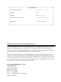
INTRODUCTION OF THE OWNERS MANUAL
SEGA ENTERPRISES, LTD., has for more than 30 years been supplying various innovative and
popular amusement products to the world market. This Owners Manual is intended to provide
detailed descriptions together with all the necessary installation, game settings and parts ordering
information related to the WORLD SERIES ‘99, a new SEGA product.
This manual is intended for those who have knowledge of electricity and technical expertise, especially in ICs, CRTs, microprocessors, and circuit boards. Read this manual carefully to acquire
sufficient knowledge before working on the machine. Should there be a malfunction, non-technical
personnel should under no circumstances touch the interior system. Should the need arise, contact
our main office, or the closest branch office listed below.
SEGA ENTERPRISES, INC. (USA)
Customer Service
45133 Industrial Drive
Fremont, CA 94538
Phone 415-701-6580
Fax
415-701-6594
7:30 am - 4:00 pm, Pacific Standard Time
Monday thru Friday
1
General Precautions
Follow Instructions: All operating and use instructions should be followed.
Attachments: Do not use attachments not recommended by the product manufacturer as they may cause hazards.
Accessories: Do not place this product on an unstable cart, stand, tripod, bracket, or table. The product may fall,
causing serious injury to a child or adult, and serious damage to the product. Use only with a cart, stand, tripod, bracket, or
table recommended by the manufacturer, or sold with the product. Any mounting of the product should follow the
manufacturer’s instructions, and should use only mounting accessories recommended by the manufacturer.
Moving the Product: This product should be moved with care. Quick stops, excessive force, and uneven surfaces
may cause the product to overturn.
Ventilation: Slots and openings in the cabinet are provided for ventilation, to ensure reliable operation of the product
and to protect it from overheating; these openings must not be blocked or covered. The openings should never be blocked
by placing the product in a built-in installation such as a bookcase or rack unless proper ventilation is provided or the
manufacturer’s instructions have been adhered to.
Power Sources: This product should be operated only from the type of power source indicated on the marking label.
If you are not sure of the type of power supply to your location, consult your local power company. For products intended
to operate from battery power or other sources, refer to the operating instructions.
Grounding or Polarization: This product is equipped with a three-wire grounding-type plug, a plug having a third
(grounding) pin. This plug will only fit into a grounding-type power outlet. This is a safety feature. If you are unable to
insert the plug into the outlet, contact your electrician to replace your obsolete outlet. Do not defeat the safety purpose of the
grounding-type plug.
Power Cord Protection: Power-supply cords should be routed so that they are not likely to be walked on or pinched
by items placed upon or against them, paying particular attention to cords at plugs, convenience receptacles, and the point
where they exit from the product.
Overloading: Do not overload wall outlets, extension cords, or integral convenience receptacles as this can result in
a risk of fire or electric shock.
Object and Liquid Entry: Never push objects of any kind into this product through openings as they may touch
dangerous voltage points or short-out parts that could result in a fire or electric shock. Never spill liquid of any kind on the
product.
Servicing: Do not attempt to service this product yourself as opening or removing covers may expose you to dangerous voltage or other hazards. Refer all servicing to qualified service personnel.
Damage Requiring Service: Unplug this product from the wall outlet and refer servicing to qualified service personnel under the following conditions:
a) If the power cord or plug is damaged;
b) If liquid has been spilled, or objects have fallen into the product;
c) If the product has been exposed to rain or water;
d) If the product does not operate normally when following the operating instructions. Adjust only those controls that
are explained in the operating instructions. An improper adjustment of other controls may result in damage and will
often require extensive work by a qualified technician to restore the product to its normal operation;
e) If the product has been dropped or damaged in any way;
f) When the product exhibits a distinct change in performance; this indicates a need for service.
Replacement Parts: When replacement parts are required, be sure the service technician has used replacements parts
specified by the manufacturer or that have the same characteristics as the original part. Unauthorized substitutions may
result in fire, electric shock, or other hazards.
2
Safety Check: Upon completion of any service or repairs to this product, ask the service technician to perform safety
checks to determine that the product is in proper operating condition.
Heat: The product should be situated away from heat sources such as radiators, heat registers, stoves, or other products (including amplifiers) that produce heat.
Lithium Battery- Dispose of batteries only in accordance with the battery manufacturer’s recommendations.
Do not dispose in an open flame condition, since the battery may explode.
Cleaning: When cleaning the monitor glass, use water or glass cleaner and a soft cloth. Do not apply chemicals such
as benzine, thinner, etc.
Location: This an indoor game machine, DO NOT install it outside. To ensure proper usage, avoid installing indoors
in the places mentioned below:
• Places subject to rain/water leakage, or condensation due to humidity;
• In close proximity to a potential wet area;
• Locations receiving direct sunlight;
• Places close to heating units or hot air;
• In the vicinity of highly inflammable/volatile chemicals or hazardous matter;
• On sloped surfaces;
• In the vicinity of emergency response facilities such as fire exits and fire extinguishers;
• Places subject to any type of violent impact;
• Dusty places.
INSTALLATION PRECAUTIONS
• Verify the amperage of the branch circuit outlet before plugging in the power plug. Do not overload the circuit.
• Avoid using an extension cord. If one is required, use an extension cord of type SJT, 16/3 AWG
rated min. 120 VAC, 7A.
• Moving this unit requires a minimum clearance (of doors, etc.) of 32” (W) by 77” (H).
• For the operation of this machine, secure a minimum area of 32” (W) by 42”(D).
REGULATORY APPROVALS
This game has been tested and found to comply with the Federal Communications Commission Rules.
This device complies with Part 15 of the FCC Rules. Operation is subject to the following two conditions: (1) This
device may not cause harmful interference, and (2) this device must accept any interference received, including interference
that may cause undesired operation.
This game has been tested and listed by Underwriters Laboratories, Inc., to ANSI/UL22.
3
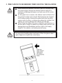
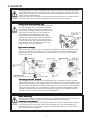
1 . PRECAUTIONS TO BE HEEDED FOR OPERATION
In order to prevent accidents, be sure to comply with the following points before and during operation.
PRECAUTIONS TO BE HEEDED FOR OPERATION BEFORE STARTING THE OPERATION
In order to avoid accidents, check the following before starting the operation:
Check if all of the adjusters are in contact with the surface. If they are not,
the cabinet can move and cause an accident.
To avoid electric shock, check to see if door & cover parts are closed.
To avoid injury, be sure to provide sufficient space by considering the
potentially crowded situation at the installation location. Insufficient installation space can cause the player to come into contact with or hit others
and result in injury or trouble.
PRECAUTIONS TO BE HEEDED DURING OPERATION
To avoid injury and accidents, those who fall under the following catagories are
not allowed to play the game:
* Intoxicated persons
* Those who have high blood pressure or heart problems.
* Those who have experienced muscle convulsion or loss of consciousness when
playing video games, etc.
* Persons susceptible to motion sickness.
* Persons whose acts runs counter to the products warning displays.
To avoid electric shock and short circuit, do not allow customers to put hands
and fingers or extraneous matter in openings of the product or small openings in
or around doors.
To avoid electric shock and short circuit, do not allow the customers to unplug
the power plug without a justifiable reason.
Although this product has the accident preventive covering attached to potentially hazardous places where hand and fingers could be caught, small children are
unable to perceive hazards. Use care so that small children do not come close to
the product when in play.
Immediately stop such violent acts as hitting and kicking the product. Such
violent acts can cause parts damage and/or falling down, resulting in injury due
to fragments and falling down.
4
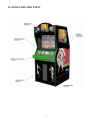
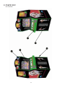
2 . NAME OF PARTS
GAME SPECIFICATIONS
Weight-DURING SHIPPING
WHEN ASSEMBLED
WIDTH in.
LENGTH in.
HEIGHT in.
All measurements are and rounded UP
32”
X
36”
5
X
81”
WEIGHT lbs.
~ 460 LBS.
430 LBS.
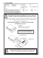
3 . ACCESSORIES
THE SHIPMENT METHOD DESCRIBED BELOW ONLY APPLIES TO
‘MODEL 3’ BOARDS CONTAINED IN THE FOLLOWING GAMES:
LOST WORLD, VIRTUA FIGHTER 3, SUPER GT, SEGA BASS FISHING, STRIKER 2, HARLEY DAVIDSON,
RALLY 2, DAYTONA 2, DIRT DEVILS, HOUSE OF THE DEAD 2, CRAZY TAXI, ZOMBIE REVENGE,
STAR WARS TRILOGY, WORLD SERIES ‘99
!!NEVER SHIP MODEL 3 / NAOMI GAME BOARDS
OUTSIDE OF CAGE!!
CARTON BOX
601-8928 (1)
Used for transporting the GAME BOARD.
{SUPPLIED WITH YOUR GAME}
DO NOT SHIP GAME BOARD WITHOUT
THIS BOX AS IT MAY DAMAGE THE GAME
BOARD AND VOID YOUR WARRANTY.
“CHECK SIDE” Display
FILTER BOARD
NO OTHER GAMES BOARDS ARE TO BE SHIPPED IN THE CAGE AS
THEY MAY BE DAMAGED BEYOND REPAIR. PLEASE SHIP THEM
WITHOUT CAGE PROPERLY PROTECTED DURING SHIPPING.
6
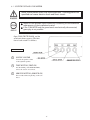
4 . ASSEMBLING AND INSTALLATION
Assembling should be performed as per this manual. Since this is a
complex machine, erroneous assembling may cause damage to the
machine, or malfunctioning to occur.
When assembling, be sure to perform work by plural persons.
Depending on the assembly work, there are some cases in which
performing the work by a single person can cause personal injury or
parts damage.
When carrying out the assembly work, follow the procedure in the following 5-item sequence:
1
ASSY OF CABINET
2
SECURING IN PLACE (ADJUSTER ADJUSTMENT)
3
POWER SUPPLY
4
ASSY CHECK
Note that the tools such as a phillips screwdriver and wrench for M16 hexagon bolt w/24 mm width
across flats are required for the assembly work.
7
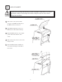
1
ASSY OF CABINET
To perform work safely and securely, be sure to prepare a step which is in a secure
and stable condition. Performing work without using the step can cause violent
falling down accidents.
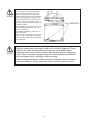
1 Take out the 3 truss screws from the
lower part of the Billboard and pull out
the Billboard Case towards you.
2 Apply Billboard Plate R to the rear of
Billboard Case with double sided tape.
3 Return the Billboard Case to the original
position and secure with the 3 truss
screws.
4 Take out the 4 truss screws to remove the
Lamp Cover B.
5 Insert the Billboard Plate to Billboard
Case and secure Lamp Cover B with 4
truss screws.
8
2
SECURING IN PLACE (ADJUSTER ADJUSTMENT)
Be sure to have all the Adjusters make contact with the surface. Unless the Adjusters come into contact with the surface, the Cabinet
can move of itself, causing an accident.
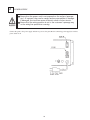
This machine has 4 each of casters and 4 each of adjusters (shown below). When the installation position is determined, cause the adjusters to come into contact with the floor directly, make adjustments in a manner so that the
casters will be raised approximately 5mm. from the floor and make sure that the machine position is level.
1
Move the machine to the installation position.
2
Cause all of the leg levelers to make contact
with the floor. By using a wrench, make
adjustments in the height of the leg adjusters to
ensure that the machine's position is level.
3
After making adjustments, fasten the leg
adjuster nut upward and secure the height of the
leg adjuster.
9
3
POWER SUPPLY
Ensure that the power cord is not exposed on the surface (passage,
etc.). If exposed, they can be caught and are susceptible to damage.
If damaged, the cord can cause an electric shock or short circuit.
Ensure that the wiring position is not in the customer's passage way
or the wiring has protective covering.
Connect the game to the power supply and turn on power to the game. Before connecting power supply be sure that
power switch is off
10
4
ASSYCHECK
GAME TEST MODE
Bring the arrow to the item of GAME TEST MODE in
TEST MENU
the SYSTEM TEST MENU, and press the Test button to
INPUT TEST
OUTPUT TEST
SOUND TEST
GAME ASSIGNMENTS
COIN ASSIGNMENTS
BOOKKEEPING
BACKUP DATA CLEAR
display the TEST MENU peculiar to ZOMBIE REVENGE.
Press the SERVICE button to move the arrow. Bring the
arrow the desired item and press the TEST button.
Upon finishing the test, bring the arrow to EXIT and
->EXIT
SELECT WITH SERVICE BUTTON AND
PRESS TEST BUTTON
press the TEST button to return to the SYSTEM MENU
MODE.
INPUT TEST
This test displays the state of each switch.
If this switch goes ON when activated, it is satisfactory.
Display varies depending on the JOYSTICK TYPE setting in (3) GAME ASSIGNMENTS.
INPUT TEST
1P_START :OFF
1P_ABUTTON :OFF
1P_BBUTTON :OFF
2P_START :OFF
2P_ABUTTON :OFF
2P_BBUTTON :OFF
1P_STICK: (80, 80)
1P_BAT : 80
2P_STICK: (80,80)
2P_BAT : 80
PRESS TEST BUTTON TO EXIT
11
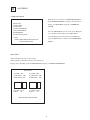
SOUND TEST
This allows sound and background used in the game to be checked/ tested.
SOUND TEST
PACKAGE01
PACKAGE02
BGM_PACK
AMBIENCE
UMPIRE
SYSTEM
TEAMCALL
Pressing the service button increase the number by one
and changes the sound.
Press the TEST button to have the MENU return to the
screen.
SELECT WITH SERVICE BUTTON
PRESS TEST BUTTON TO EXIT\
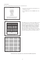
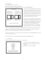
CRT TEST
C.R.T. TEST 1/2
12345678901234567890123456789012123456789012
12345678901234567890123456789012123456789012
12345678901234567890123456789012123456789012
12345678901234567890123456789012123456789012
12345678901234567890123456789012123456789012
12345678901234567890123456789012123456789012
12345678901234567890123456789012123456789012
12345678901234567890123456789012123456789012
RED
12345678901234567890123456789012123456789012
12345678901234567890123456789012123456789012
123456789012345678901234567890121234567
12345678901234567890123456789012123456789012
123456789012345678901234567890121234567
123456789012345678901234567890121234567
123456789012345678901234567890121234567
123456789012345678901234567890121234567
123456789012345678901234567890121234567
GREEN
123456789012345678901234567890121234567
123456789012345678901234567890121234567
123456789012345678901234567890121234567
123456789012345678901234567890121234567
123456789012345678901234567890121234567
12345678901234567890123456789
12345678901234567890123456789
12345678901234567890123456789
12345678901234567890123456789
BLUE
12345678901234567890123456789
12345678901234567890123456789
12345678901234567890123456789
12345678901234567890123456789
In the TEST mode menu, selecting C.R.T. TEST allows the
screen (on which the projector is tested) to be displayed.
Although the projector adjustments have been made at the
same time of shipment from the factory, color deviation,
etc., may occur due to the effect caused by geomagnitism,
the location building’s steel frames and other game machines in the periphery. By watching the test mode screen,
make judgement as to whether an adjustment is needed. If it
is neccessary, adjust the projector by refering to Section 9.
WHITE
PRESS TEST BUTTON TO CONTINUE
1234567890123456789012345678
1234567890123456789012345678
1234567890123456789012345678
1234567890123456789012345678
1234567890123456789012345678
1234567890123456789012345678
1234567890123456789012345678
1234567890123456789012345678
1234567890123456789012345678
1234567890123456789012345678
1234567890123456789012345678
1234567890123456789012345678
1234567890123456789012345678
1234567890123456789012345678
1234567890123456789012345678
1234567890123456789012345678
1234567890123456789012345678
1234567890123456789012345678
1234567890123456789012345678
1234567890123456789012345678
1234567890123456789012345678
1234567890123456789012345678
1234567890123456789012345678
1234567890123456789012345678
1234567890123456789012345678
C.R.T. TEST 2/2
PRESS TEST BUTTON TO CONTINUE
Perform the above inspections also at the time of monthly inspection.
12
5 . PRECATIONS TO BE HEEDED WHEN MOVING THE MACHINE
When moving the machine, be sure to pull out the plug from
the power supply. Moving the machine with the plug as is
inserted can damage the power cord and cause a fire or electric shock.
As this game has no casters, the Cabinet must be lifted off of
the ground in order to be moved. Plural persons are required
to lift cabinet safely. Moving the cabinet with the leg still in
contact with the floor, or moving the cabinet by ‘rocking’ the
cabinet can severly damage the cabinet and the legs.
When lifting the cabinet, be sure to hold the catch portions or
bottom part. Lifting the cabinet by holding other portions can
damage parts and installation portions, due to the empty
weight of the cabinet, and cause personal injury.
Use care when handling glass made parts. When the glass is damaged, fragments of glass can cause injury
13
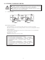
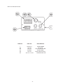
6 . EXPLANATION OF TEST AND DATA DISPLAY
By operating the switch unit, periodically perform the tests and data check. When installing the machine initially or
collecting cash, or when the machine does not function correctly, perform checking in accordance with the explanations
given in this section. The following shows tests and modes that should be utilized as applicable.
When performing installation, servicing product or changing game boards refer to individual kit instructions
for each of the listed items below:
ITEMS
DESCRIPTION
When the machine is installed, perform the following:
INSTALLATION 1. Check to see that each setting is as per standard setting made
at the time of shipment.
OF MACHINE
2. In the INPUT TEST mode, check each SW and VR.
3. In the OUTPUT TEST mode, check each of lamps.
4. In the MEMORY TEST mode, check ICs on the IC Board.
MEMORY
Choose MEMORY TEST in the MENU mode to allow the
MEMORY test to be performed. In this test, PROGRAM
RAMs, ROMs, and ICs on the IC Board are checked.
PERIODIC
SERVICING
Periodically perform the following:
1. MEMORY TEST
2. Ascertain each setting.
3. In the INPUT TEST mode, test the CONTROL device
4. In the OUTPUT TEST mode, check each of lamps.
CONTROL
SYSTEM
1. In the INPUT TEST mode, check each SW and VR.
2. Adjust or replace each SW and VR.
3. If the problem can not be solved yet, check the CONTROL’s moves.
MONITOR
In the MONITOR ADJUSTMENT mode, check to see if the
MONITOR adjustment is appropriately made.
IC BOARD
1. MEMORY TEST
2. In the SOUND TEST mode, check the sound related ROMs.
DATA CHECK
Check such data as game play time and histogram to adjust the
difficulty level, etc
14
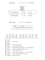
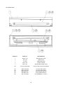
6 - 1 SWITCH UNIT AND COIN METER
Never touch places other than those specified. Touching places not
specified can cause electric shock and short circuit.
Adjust to the optimum sound volume by considering the environmental
requirements of the installation location.
If the COIN METER and the game board are electrically disconnected,
game play is not possible.
Open COIN CHUTE DOOR, and the
switch unit shown appears. The function of each switch is as follows:
SWITCH UNIT
1
SOUND VOLUME
Controls the speaker volume
of the right/left speakers.
2
TEST BUTTON (TEST SW)
For the handling of the TEST BUTTON,
refer to the section on test mode.
3
SERVICE BUTTON (SERVICE SW)
Gives credits without registering on the coin
meter.
15
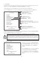
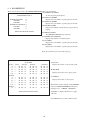
6 - 2 TEST MODE
System Menu. This test mode mainly allows the IC board to be checked for accurate functioning, monitor color to be
adjusted as well as COIN ASSIGNMENTS and GAME ASSIGNEMENTS to be adjusted.
1.) After turning power on, press the TEST button to have the following test item menu displayed.
2.) Press the SERVICE button to move the arrow. Bring the arrow to the desired item and press the TEST button.
SYSTEM MENU
USA VERSION
RAM TEST
JVS TEST
SOUND TEST
SYSTEM ASSIGNMENTS
COIN ASSIGNMENTS
BOOKKEEPING
BACKUP DATA CLEAR
CLOCK SETING
ROM BD TEST
GAME TEST MODE
WORLD SERIES 99
->EXIT
SELECT WITH SERVICE BUTTON
AND
PRESS TEST BUTTON
OPERATION REQUIREMENTS OF THIS GAME:
In the SYSTEM ASSIGNMENTS,
the CABINET TYPE is set to 2 PLAYER(s)
and MONITOR TYPE is set to HORIZONTAL.
COIN ASSIGNMENTS intial settings
<USA, EXPORT, AUSTRALIA Version>
COIN CHUTE TYPE
COMMON
COIN/ CREDIT SETTING
#12
SEQUENCE SETTING OF COIN ASSIGNMENTS
SEQUENCE 1: Number of credits required for Game Start. (intial value=1)
SEQUENCE 2: Number of credits required for CONTINUE (intial value=1)
SEQUENCE 3-8: NOT USED
MEANING OF DISPLAY IN BOOKEEPING (2/2)
P1(P2) SEQ 1: Play frequency of Player 1 (Player 2)
P1(P2) SEQ 2: Frequency of CONTINUE by Player 1 (Player 2)
P1(P2) SEQ 3-8: NOT USED
3.) Bring the arrow to the item of Game TEST MODE and press the TEST button to display the GAME TEST MENU
peculiar to ZOMBIE REVENGE. See the next page onward.
4.) Upon finishing the test, bring the arrow to EXIT and press the TEST button to return to the Gam Mode.
The contents of settings changes in SYSTEM ASSIGNMENTS, COIN ASSIGNMENTS, and
GAME TEST MODE are stored when the test mode is EXITed. If the power is turned off
before EXITing, the contents of setting changes are ineffective. Be very careful of this
point.
6 - 3 GAME TEST MODE
Bring the arrow to the item of GAME TEST MODE in
TEST MENU
the SYSTEM TEST MENU, and press the Test button to
INPUT TEST
SOUND TEST
GAME ASSIGNMENTS
VOLUME SETTING
BOOKKEEPING
BACKUP DATA CLEAR
display the TEST MENU peculiar to ZOMBIE REVENGE.
Press the SERVICE button to move the arrow. Bring the
arrow the desired item and press the TEST button.
->EXIT
SELECT WITH SERVICE BUTTON
AND
PRESS TEST BUTTON
Upon finishing the test, bring the arrow to EXIT and
press the TEST button to return to the SYSTEM MENU
MODE.
16
6 - 4 INPUT TEST
This test displays the state of each switch.
If this switch goes ON when activated, it is satisfactory.
Display varies depending on the JOYSTICK TYPE setting in (3) GAME ASSIGNMENTS.
The XX value of 1P (2P)_STICK (XX,YY), indicates the
INPUT TEST
middle value when the STICK is untouched. It indicates
1P_START :OFF
1P_ABUTTON :OFF
1P_BBUTTON :OFF
2P_START :OFF
2P_ABUTTON :OFF
2P_BBUTTON :OFF
the minimum value when the stick is turned to the right,
and the maximum value when the STICK is turned to the
left. The volume setting is normal if the maximum value
is between 70 and 8F, the minimum value is between 00
and 0F, and the maximum between F0 and FF.
The YY value of 1P (2P)_STICK (XX,YY) indicates the
1P_STICK: (80, 80)
1P_BAT : 80
2P_STICK: (80,80)
2P_BAT : 80
middle vlaue when the STICK is untouched. It indicates
the minimum value when the STICK is turned down, and
the maximum value when the STICK is turned up. The
PRESS TEST BUTTON TO EXIT
volume setting is normal when the middle value is
between 70 and 8F, the minimum value is between 00
and 0F, and the maximum value is between F0 and FF.
The value of 1P (2P)_BAT indicates the minimum value when the BAT is untouched (face up) position. It indicates the
maximum value when the BAT is rotated about half a turn until it is stopped. The volume setting is normal if the
minimum value is between 00 and 0F and the maximum value is between F0 and FF.
If any value is abnormal, return to the menu screen and take steps described in #4 “VOLUME SETTING”. Then return
to this test and confirm the values.
To return to the menu screen, press the TEST Button while holding the SERVICE Button down.
6 - 5 SOUND TEST
This allows sound and background used in the game to be checked/ tested.
SOUND TEST
PACKAGE01
PACKAGE02
BGM_PACK
AMBIENCE
UMPIRE
SYSTEM
TEAMCALL
To check them, specify the appropriate item using the
SERVICE Button and press the TEST Button to generate
the sound.
By default, the arrow is located at EXIT.
SELECT WITH SERVICE BUTTON
PRESS TEST BUTTON TO EXIT
17
6 - 6 GAME ASSIGNMENTS
GAME ASSIGNMENTS
GAME DIFFICULTY
NORMAL
INNINGS
1 CREDIT 2 INNINGS
FAVORITE
OFF
EXTRA INNING
OFF
Allows game difficulty adjustments to be
performed/ changed.
SELECTION OF DESIRED ITEM
1.) Press the SERVICE button to move
the -> and bring it to the desired item.
2.) Press the TEST btuuon to change the
seting.
->EXIT
3.) After the device setting is finished,
bring the -> to EXIT and press the TEST
button.
SELECT WITH SERVICE BUTTON AND
PRESS TEST BUTTON TO EXIT
(A) INNINGS (FOUR SETTINGS LISTED BELOW
This sets the number of innings that can be played in the VERSUS-COM mode.
FOUR SETTINGS (listed below)
If 1 CREDIT is set, when the game can be continued following
I CREDIT 1 INNING
the end of the sixth inning, the remaining three innings can be
1 CREDIT 2 INNINGS
played on one credit.
1 CREDIT 3 INNINGS
1 CREDIT ALL INNINGS
Allows the player all innings on one credit
(B) GAME DIFFICULTY
(VERY EASY, EASY, MEDIUM EASY, NORMAL, MEDIUM HARD, HARD, VERY HARD)
(C) FAVORITE (OFF, Each team)
Sets the favorite team.
The favorite team becomes stronger than the other teams
The favorite team name is displayed in the advertise.
Only one teram can be favored at a time
(D) EXTRA INNINGS (OFF, ON)
Ebnables or disables the extra innings. When set to ON, the game can be played up to 12 extra
innings.
18
6 - 7 VOLUME SETTING
This page allows yo to adjust the volume settings used for the ANALOG STICKS and BAT MECHA.
VOLUME SETTING
PLAYER1
STICK-H HMAX (CO)
STICK-V HMAX (CO)
BAT
BMAX (CO)
HMIN (50)
HMIN (50)
BMIN (OC)
NOW (80)
NOW (80)
NOW (OC)
PLAYER2
STICK-H HMAX (CO)
STICK-V HMAX (CO)
BAT
BMAX (CO)
HMIN (50)
HMIN (50)
BMIN (OC)
NOW (80)
NOW (80)
NOW (OC)
SAVE AND EXIT
>EXIT
SELECT WITH SERVICE BUTTON AND
PRESS TEST BUTTON TO EXIT
ADJUSTING THE VOLUME VALUE
For the 1P and 2P ANALOG STICKS, move each from the untouched position to the maximum position vertically and
horizontally.
For the 1P and 2P BATS, pull each from the untouched (face-up) position by about half of a turn until it stops.
Then, with the STICKS and BATS untouched, select SAVE AND EXIT and press the TEST Button to return to the
menu screen. This completes adjustments.
After adjustments, be sure to return to the INPUT TEST mode to verify that the values are normal. If they are not
normal, come back to the VOLUME SETTING page and readjust the volume settings. If the normal values are not
recovered after several retries, probably the BAT MECHA is faulty.
19
6 - 8 BOOKKEEPING
This test mode allows each of the CREDIT/TIME/GAME data to be ascertained.
(A) NUMBER OF GAMES
BOOKKEEPING
1P, 2P total game playfrequency.
GAME REPORT PAGE 1/2
(B) SINGLE 1P GAMES
NUMBER OF GAMES
0
Displays the total number of games played at 1P side
1P GAMES
0
(C) SINGLE 2P GAMES
2P GAMES
0
Displays the total number of games played at 2P side
NUMBER OF CONTINUE 0
(D) DOUBLE GAMES
1P GAMES
0
Displays the number of games that two players began
2P GAMES
0
playing.
PRESS TEST BUTTON TO EXIT
(E) VERSUS GAMES
The SERVICE SWITCH usage frequency.
(F) NUMBER OF CONTINUE
Displays the number of continued games..
(G) 1P GAMES
Displays the total number of games played at 1P side
(H) 2P GAMES
Displays the total number of games played at 2P side.
Press the test button to proceed to the next page.
BOOKKEEPING
PLAY TIME
VS CPU
1-2
3-4
5-6
7-8
9-10
DOUBLE
1-2
3-4
5-6
7-8
9-10
VERSUS
8-9
COUNT
AVERAGE
(A) VS CPU:
LONGEST
SHORTEST
**
**
**
**
**
*H
*H
*H
*H
*H
*M
*M
*M
*M
*M
**S
**S
**S
**S
**S
*H
*H
*H
*H
*H
*M
*M
*M
*M
*M
**S
**S
**S
**S
**S
*H
*H
*H
*H
*H
*M
*M
*M
*M
*M
**S
**S
**S
**S
**S
**
**
**
**
**
*H
*H
*H
*H
*H
*M
*M
*M
*M
*M
**S
**S
**S
**S
**S
*H
*H
*H
*H
*H
*M
*M
*M
*M
*M
**S
**S
**S
**S
**S
*H
*H
*H
*H
*H
*M
*M
*M
*M
*M
**S
**S
**S
**S
**S
**
*H *M **S
Displays the results of versus_CPU game.
(B) DOUBLE:
Displays the results of two-player game.
(C) VERSUS:
Displays the results of versus game.
The number of items depends on the INNINGS
values of GAME ASIGNMENTS. The above
*H *M **S
*H *M **S
examples is for “1 CREDIT 2 INNINGS”.
“NODATA” is displayed if there is no appli-
PRESS TEST BUTTON TO EXIT
cable data.
Press TEST button to return to Menu screen.
20
6 - 9 BACK UP DATA CLEAR
Clears the contents of BOOKKEEPING.
BACK UP DATA CLEAR
YES (CLEAR)
->NO (CANCEL)
SELECT WITH SERVICE BUTTON AND
PRESS TEST BUTTON TO EXIT
When clearing bring-> to YES and when not clearing, to NO, by using the SERVICE SW and then push the TEST
button.
When clearing has been finished, COMPLETED will be dislayed.
Pressing the TEST button will have the MENU return to the screen.
21
7 . COIN SELECTOR
HANDLING THE COIN JAM
If the coin is not rejected when the REJECT BUTTON is pressed, open the coin chute door
and open the selector gate. After removing the jammed coin, put a normal coin in and check
to see that the selector correctly functions.
CLEANING THE COIN SELECTOR
1
2
3
4
5
6
GATE
The coin selector should be cleaned
once every 3 months. When cleaning,
follow the procedure below:
Turn the power for the machine OFF.
Open the coin chute door.
Open the gate and dust off by using a
soft brush (made of wool, etc.).
Remove and cleen smears by using a
soft cloth dipped in water or diluted
chemical detergent and then squeezed
dry.
Remove the CRADLE.
When removing the retaining ring(Ering), be very careful so as not to bend
the shaft.
Remove stain from the shaft and pillow
portions by wiping off with a soft cloth,
etc.
After wiping as per #5 above, further
apply a dry cloth, etc. to cause the coin
selector to dry completely.
FIG. 11a
CRADLE
FIG.11b
Never apply machine oil, etc. to
the coin selector
After cleaning the Coin Selecting,
Insert a regular coin in the normal
working status and ensure that
the Selector correctly functions.
COIN INSERTION TEST
Once a month, when performing the COIN SW
TEST, simultaneously check the following:
Does the Coin Meter count satisfactorily?
Does the coin drop into the Cashbox correctly?
Is the coin rejected when inserted while keeping
the REJECT BUTTON is pressed down?
Insert a coin
while keeping
the Reject
Button pressed
down and check
if it is
rejected.
COIN METER
FIG. 11c
22
OPTIONAL DOLLAR BILL ACCEPTOR
THE COIN DOOR ASSEMBLY USED ON WORLD SERIES ‘99 COMES
EQUIPPED TO ACCEPT A DOLLAR BILL ACCEPTOR. ALL NEEDED
WIRING CONNECTIONS ARE CONVIENENTLY LOCATED INSIDE THE
GAME FOR THIS APPLICATION.
THE COIN DOOR CAN ACCCOMMODATE THE FOLLOWING
VALIDATORS:
HOLE POSITION#1
(FORWARD-MOST POSITION)
Mars 2000 series
HOLE POSITION#2
Mars 2000 series
DBV45 (JCM)
HOLE POSITION #3
CURRENTLY NOT USED
HOLE POSITION #4
DSI01*
*The back flange on the chute can be removed for hold position #4.
If the flange is not removed, it may interfere with the back of the
cabinent.
The frame and cashbox enclosure on this coindoor has been modified to accomodate a Mars 2000 series
upstacker. A 2000 series stacker can be added by simply removing the top two entry door and replacing it with a one
entry door with a cut-out for a stacker. This one entry door can be ordered through Coin Controls or one of Coin Controls
authorized distributors. The part number is 91-4000-01. The Mars stacker can be obtained through an autherized Mars
distibutor.
23
24
8. MONITOR
When performing such work as installing and removing the monitor, inserting and disconnecting the external connectors to and from monitor, be sure to disconnect the power connector
(plug) before starting work. Proceeding the work without following this instruction can cause
electric shock of malfunctioning.
Using the monitor by converting it without obtaining a prior permission is not allowed. SEGA
shall not be liable for any malfunctioning and accident caused by said conversion.
Primary side and secondary side
The monitor’s circuit which is divided into the Primary
side and secondary side, is electrically isolated. Do
not touch the primary side and the secondary side
simultaneously. Failing to observe the instruction can
cause electric shock, and this is very dangerous.
When making monitor adjustments, use a nonconductive driver and make adjustment without
touching any other part other than the Adjustment
V.R. and Knob. Also, be sure not to cause a shortcircuit to the Primary side and the Secondary side. If
short-circuited, it can cause electric shock or malfunctioning, which is very dangerous.
High tension Voltage
Some of the parts inside the monitor are subject to high-tension voltage in excess of 20,000
volts and very dangerous. Therefore, do not touch the monitor interior. Should soldering &
paper wastes, etc. be mixed in the monitor, turn the power off so as not to cause malfunctioning or fire hazard.
Connecting the CRT and PCB
For combining the CRT and PCB, use the specified part No. to maintain the status of adjustments made at the factory. The anode of the CRT itself will be accumulitavely charged as time
elapses, generating high tension voltage which is very dangerous. The monitor should be used
with the Chassis, CRT and PCB assembled. When repair, etc. is required at the time of malfunctioning, be sure to send it in an “as assembled” condition. If these are disassembled, what’s
charged to said high tension voltage can be discharged, causing a very hazardous situation.
Therefore, under no circumstances should it be disassembled.
Static Electricity
Touching the CRT surface sometimes causes you to slightly feel electricity. This is because the
CRT surfaces are subject to static and will not adversly affect the human body.
Installation and removal
Ensure that the Magnetizer Coil, FBT (Fly-Back Transformer), Anode Lead and Focus Lead are
not positioned close to the sheet metal work’s sharp edges, etc. and avoid damaging the
insulated portions so as not to cause an electric shock and malfunctioning. (For the name of
parts, refer to the above figures.)
25
For the purpose of static prevention,
special coating is applied to the CRT
face of this product. To protect the
coating, pay attention to the following
points. Damaging the coating film can
cause electric shock to the customers.
For the caution to be heeded when
clearing, refer to the Section of Periodic
inspection Table.
Do not apply or rub with a hard item (a
rod with pointed edge, pen, etc.) to or
on C.R.T. surfaces.
Avoid applying stickers, seals, etc. on
the C.R.T. face.
Do not remove aluminum foils from the
C.R.T. corners. Removing the aluminum
foils can cause static prevention effects
to be lowered.
Monitor adjustments have been made at the time of shipment. Therefore do not make further adjustment without a justifiable reason.
Adjusting the monitor which contains high tension parts is dangerous
work. Also, an erroneous adjustment can cause deviated synchronization and image fault, resulting in malfunctioning.
When making adjustment, utilize a resinous Alignment Rod. Servicing
with bare hands or using conductive tools can cause electric shock.
26
27
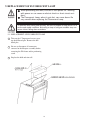
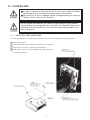
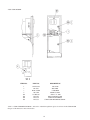
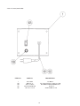
9. REPLACEMENT OF FLUORESCENT LAMP
When performing the work, be sure to turn power off. Working
with power on can cause an electric shock or short circuit accident.
The Fluorescent Lamp, when it gets hot, can cause burns. Be
very careful when replacing the Fluorescent Lamp.
To perform work safely and securely, be sure to prepare a step which is in a
secure and stable condition. Not using a step or using an unstable step can
cause violent falling down accidents.
9 -1 REPLACEMENT OF FLUORESCENT LAMP
1
Take out the 3 Tamperproof screws securing the billboard plex. Remove the billboard plex.
2
Be sure to disconnect all connectors
conected to the Marquee assembly before
removing the FL fixture and/or performing
work.
3
Replace the bulb and reinstall.
28
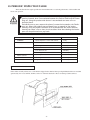
10. PERIODIC INSPECTION TABLE
The items listed below require periodic check and maintenance to retain the performance of this machine and
ensure safe operation.
Be sure to check once a year to see if Power Cords are damaged, the plug is
securley inserted, dust is accumulated between the Socket Outlet and the Power
Plug, etc. Using the product with dust as is accumulated can cause a fire or
electrical shock.
Periodically once a year, request the place of contact herin stated or the Distributer, etc. where the product was purchased from, as regards to the interior
cleaning. Using the product with dust as is accumulated in the interior without
cleaning can cause a fire or short circuit accident. Note that cleaning the interior
parts can be performed on a pay-basis.
Item
Interval
CABINET
Check Adjuster’s contact with surface.
Daily
MONITOR
Check Adjustments.
Monthly
Cleaning of CRT surfaces.
Weekly
Check COIN SW.
Monthly
Coin insertion test.
Monthly
Cleaining the COIN SELECTOR
Monthly
Cabinet surfaces
Cleaning
As necessary
INTERIOR
Cleaning
Annually
POWER SUPPLY PLUG
Inspection and cleaing
Annually
COIN CHUTE TOWER
CLEANING CABINET SURFACES
If the cabinet is badly stained, use a cloth which is dipped in the chemical detergent liquid diluted with water and then
squezzed dry. Do not use thinner, benzine, alcohol or chemical dustcloth as these can damage Cabinet surfaces.
29
11. TROUBLESHOOTING
Should trouble occur, first check connector connections.
PROBLEMS
CAUSE
COUNTERMEASURES
With Main SW
ON, no activation
Power is not supplied.
Plug in correctly
Power supply/voltage is not correct.
Make sure that power supply/voltage is
correct
Irregular sound
emitted from
inside Cabinet
Greasing to gear mesh portion is not
satisfactory, or extraneous matter
mixed in.
Apply greasing or eliminate extraneous
matter.
The color of the
image on PROJ.
screen is incorrect.
Connector connections are defective.
Check the connection for the RGB and
SYNC connectors of the PROJ. TERM.
BD and VPM BUFFER BD.
The image on PROJ.
screen has color
deviation.
Affected by the magnetic field of
installation location.
Make CONVERGENCE adjustment.
(Refer to Section 12.)
No sound is emitted.
Sound Volume adjustment is not
appropriate.
Adjust sound volume. (see Section 7).
Sound BD and speaker are
malfunctioning.
Perform sound test to find and replace
defective parts.(Refer to Section 7).
30
12. CONTROL PANEL/BAT MECHA
In order to prevent an electrical shock, be sure to turn power off before
performing work by touching the interior parts of the product.
Be careful so as not to damage wirings. Damaged wiring can cause an
electric shock or short circuit accident.
12 - 1 CONTROL PANEL
EXPLANATION OF CONTROLS:
ANALOG STICK: Move cursor (for throwing, batting); Specify base (for defense, base running)
SW1: Throw (for defense); Steal base (for batting); Advance to next base (for base running) Enter command
(within acceptable time).
SW2: Check runner (for throwing); Move between bases (for defense); Return to base (for running) Enter
command within acceptable time).
BAT MECHA: Throw, Swing.
START: Start game; Time out (for throwing, batting)
The analog input on the I/O board uses the following channels:
CH0: 1P ANALOG STICK VOLUME VERTICAL UP(FFH)
DOWN(00H)
CH1: 1P ANALOG STICK VOLUME HORIZONTAL LEFT(FFH) RIGHT(00H)
CH2: 1P BAT MECHA VOLUME STANDARD POS.(00H) MAX(FFH)
CH3: (RESERVE)
CH4: 2P ANALOG STICK VOLUME VERTICAL UP(FFH)
DOWN(00H)
CH5: 2P ANALOG STICK VOLUME HORIZONTAL LEFT(FFH) RIGHT(00H)
CH6: 2P BAT MECHA VOLUME STANDARD POS.(00H) MAX(FFH)
CH7: (RESERVE)
31
REMOVING AND ATTACHING THE BAT MECHA
If you need to remove the BAT MECHA as in the case of a failure, open control panel base and remove the BAT
MECHA through the following procedure.
To reinstall the BAT MECHA, reverse the removing procedure, being certain that the BAT MECHA is faced in the
correct direction.
To prevent electrical shock, be sure to turn off power to the cabinet when removing or attaching the BAT MECHA
1.) Remove the wiring connector (AMP 3P, white) located near the volume.
2.) Remove the tamperproof screw clamping the bat center axis on the front side of the control panel.
3.) Remove the four flange nuts clamping the BAT MECHA body on the back side of control panel.
32
13. GAME BOARD
In order to prevent an electrical shock, be sure to turn power off before
performing work by touching the interior parts of the product.
Be careful so as not to damage wirings. Damaged wiring can cause an
electric shock or short circuit accident.
Do not expose the Game BD, etc. without a good reason. In this product,
setting changes are made during the test mode. The Game BD need not be
operated. Use the Game BD, etc. as is with the same setting made at the
time of shipment.
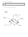
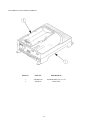
13 -1 REMOVING THE GAME BOARD
To replace the IC Board or to change dip switch settings, take out the IC board using the following procedure;
1
2
3
4
Turn main switch off.
Unlock Cabi Drawer, pull outward, exposing all game components.
Disconnect all connectors connected to the Shield Case.
Take off the 4 screws to remove the Shield Case. The game board
is inside the shield case.
33
13 -2 COMPOSITION OF GAME BOARD
Ensure that the DIP SW setting is performed as designated. Failure to observe this
may cause functioning not suitable for the operation of product, or malfunctioning.
ASSY CASE NAO USA (840-0003D-01) : WORLD SERIES ‘99
34
14. DESIGN RELATED PARTS
35
15. PARTS LIST
TOP ASSYMLB
36
TOP ASSY MLB_WS99
ITEM NO.
PART NO.
DESCRIPTION
1
2
3
4
5
NOT AVAILABLE*
HOD1-1570
SEE DESCRIPTION*
SEE DESCRIPTION*
SEE DESCRIPTION*
ASSY BILLBOARD MLB_WS99
ASSY MONITOR 29TYPE 31K
ASSY CONTROL PANEL MLB_WS99
ASSY COIN TOWER
ASSY SUB-CABINET MLB_WS99
* THESE ITEMS ARE NOT SOLD AS COMLETE UNITS, PLEASE SEE INDIVIDUAL ASSEMBLIES FOR PART
NUMBERS OF ALL ITEMS CONTAINED ON THEM.
37
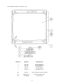
ASSY SUB CABI MLB_WS99
38
ASSY SUB CABI MLB_WS99
ITEM NO.
PART NO.
DESCRIPTION
1
2
3
4
5
6
7
8
9
10
11
12
13
14
15
16
17
19
20
21
22
23
NOT AVAILABLE
HOD-1530
HOD5-4500
DRT1-0400
92-1003-05
BOX-CASH
601-5699X
601-9377
999-0781
HOD5-3500
999-0782
AIN-1033
COP-1510
ARC-1006
SCR-1008
HOD-1502
HOD-1505
253-5460-01
DP-1148X
DP-1167
117-0062
117-5098
ASSY CABINET
FAN UNIT
ASSY ELEC BASE
ASSY AC UNIT
ASSY C.C. 2 DOOR
CASH BOX
LEG ADJUSTER BOLT M16X75
CASTER FAI=75
MONITOR GLASS 29" MLB_WS99
ASSY BILLBOARD
MONITOR BEZEL 29" MLB_WS99
GLASS HOLDER UPPER
GLASS HOLDER LOWER
LEG BRACKET
NUT PLATE FOR CASTER
FRONT DOOR L
FRONT DOOR R
AIR VENT BLACK
LKG TNG
TNG LKG
PLATE LOCK RETAINER
TNG RETAINER PLATE
39
ASSY BILLBOARD
ITEM NO.
PART NO.
DESCRIPTION
1
2
3
4
5
HOD1-3501
JPT-3502
999-0820
HOD-3504
HOD-3505
BILLBOARD CASE
REFLECTOR
MARQUEE PLEX
LAMP COVER B
BILLBOARD UPPER SASH
101
LOCAL PURCHASE
ASSY FL20W SD W/CONN HIGH L
201
202
203
204
205
000-FOO408-0B
000-TOO408-0B
000-P00430-W
000-T00412-0B
068-441616-0B
M SCR FH BLK M4X8
M SCR TH BLK M4X8
M SCR PH W/FS M3X30
M SCR TH BLK M4X12
FLT WSHR BLK 4.4-16X1.6
40
ASSY CONTROL PANEL
ITEM NO.
PART NO.
DESCRIPTION
1
2
3
4
5
999-0824
509-5560-Y
610-6723-4C01
509-5561-G
610-0409
CONTROL PANEL PLATE MLB_WS99 NAO
PB SW W/L 6V 1L Y
ASSY ANALOG JOY 4C GREEN
PB SW W/L 6V 5L G
ASSY BAT MECHA
41
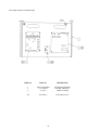
ASSY COIN TOWER
ITEM NO.
PART NO.
DESCRIPTION
1
2
3
4
101
102
104
105
SPG1-0350
DP-1167
BOX-CASH
105-5202
92-1003-05*
220-5412
220-5574
220-5575
SW UNIT
TNG LKG
CASH BOX
HOLE COVER
ASSY C.C. 2DR
MAG CNTR W/CONN
CAM LOCK W/KEYS
CAM LOCK MASTER W/O KEY
*This is a COIN CONTROLS PART No. and can be ordered through them, please view insert in the COIN DOOR
Chapter of this manual for more information.
42
ASSY SW UNIT (SPG5-0350)
ITEM NO.
PART NO.
DESCRIPTION
1
101
102
103
104
105
SPG5-0351
509-5028
220-5179
601-0042
220-5412
509-5453-91-V-B
SWITCH BRKT
SW PB 1M
VOL CONT B-5K OHM
KNOB 22MM
MAG CNTR W/CONN
ROCKER SWJ8 V-B
43
ASSY AC UNIT (DRT1-0400)
ITEM NO.
PART NO.
DESCRIPTION
1
101
102
103
105
SPG1-0401
600-5843-25
280-5134-6N34
LOCAL PURCHASE
509-5453-91-V-B
AC BRKT
CA & PLUG ASSY 15A W/F-L=2.5M
BUSHING STRAIN RELIEF 6N34
FUSE 5A
SW ROCKER J8 V-B
44
ASSY MONITOR 29TYPE 31K (HOD1-1570)
ITEM NO.
PART NO.
DESCRIPTION
1
2
3
4
5
AIN-1026
AIN-1027
280-5112
280-5113
280-5114
MONITOR BRKT A
MONITOR BRKT B
BUSH FOR TV
COLLAR FOR TV
SPACER 6.4-25X2
101
200-5787
ASSY CLR DSPL 29TYPE 31K 100V
201
202
000-P00512-W
050-F00600
M SCR PH W/FS M5X12
FLG NUT M6
45
ASSY PWR SUPPLY U/R (MLB-4500)
ITEM NO.
PART NO.
DESCRIPTION
1
2
4
NOT AVAILABLE
838-11650-29
839-0979
WOODEN BASE ELEC
EQ PWR AMP JPT C
LAMP COVER B
201
011-P00325
TAP SCR PH 3X25
46
ASSY MAIN BD U/R (MLB-4600)
ITEM NO.
PART NO.
DESCRIPTION
1
2
3
105-5345
NOT AVAILABLE
837-13551
ASSY SHIELD CASE NAOMI
WOODEN BASE MAIN BD U/R
I/O CONTROL BD FOR JVS
101
400-5330-03
SW REGU FOR MODEL3
203
204
000-P00416-W
011-P00325
M SCR PH W/FS M4X16
TAP SCR PH 3S25
47
Come see SEGA ENTERPRISES’ Service Department Homepage
ASSY SHIELD CASE NAO MLB (840-0012D)
ITEM NO.
PART NO.
DESCRIPTION
1
2
840-0001A-01
840-0012C
GAME BD MLB_WS 99 USA
ROM CASE
48