1
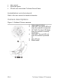
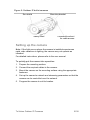
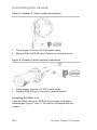
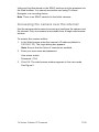
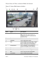
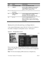
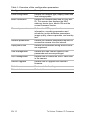
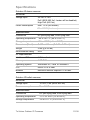
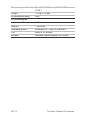
TruVision Outdoor IP Cameras Quick Start Guide P/N 1072588A-EN • REV 1.0 • ISS 27AUG12 Copyright © 2012 UTC Fire & Security. All rights reserved. Contact See www.interlogix.com or information www.utcfssecurityproducts.eu. Content Introduction 3 Package contents 3 Installation environment 4 Camera descriptions 4 Setting up the camera 5 Connecting the devices 6 Accessing the camera over the internet 7 Overview of the camera Web browser 8 Network and streaming configuration 9 Specifications 11 Introduction This pocket guide provides basic information on installing the TruVision Outdoor IP dome and bullet cameras. For detailed information on installing and using the cameras, please refer to the user manual. Camera models: TVC-N225E-2M-N(-P) (IP bullet camera) TVC-M1245E-2M-N(-P) (1.3MPX WDR bullet camera) TVD-N225E-2M-N(-P) (IP dome camera) TVD-M1245E-2M-N(-P) (1.3MPX WDR dome camera) Package contents The camera is shipped with the following items: Camera Hex wrench Video cable for testing (except bullet cameras) TruVision Outdoor IP Cameras 3 EN User manual Quick start guide CD with user manual and TruVision Device Finder. Installation environment Refer to the user manual for detailed information. Camera descriptions Figure 1: Outdoor IP dome cameras 1. Video output interface 2. LINK LED: The yellow LED is lit when the network is connected. 3. ACT LED: The blue LED blinks when the network is correctly functioning. 4. PWR LED: The red LED is lit when the camera is powered up. 5. Micro SD slot 6. Reset switch. EN 4 TruVision Outdoor IP Cameras Figure 2: Outdoor IP bullet cameras Sun shield Mounting bracket Safety cable Threaded knockout for cable access Setting up the camera Note: If the light source where the camera is installed experiences rapid, wide variations in lighting, the camera may not operate as intended. For detailed instructions, please refer to the user manual. To quickly put the camera into operation: 1. Prepare the mounting surface. 2. Connect the required cables to the camera. 3. Mount the camera on the mounting surface using the appropriate fasteners. 4. Set up the camera’s network and streaming parameters so that the camera can be controlled over the network. 5. Program the camera to suit its location. TruVision Outdoor IP Cameras 5 EN Connecting the devices Figure 3: Outdoor IP dome camera connections 1. Power supply: Connect +24 VAC power supply. 2. Ethernet RJ45 PoE/PoE+ port: Connect to network devices. Figure 4: Outdoor IP bullet camera connections 1. Power supply: Connect +12 VDC power supply. 2. Ethernet RJ45 PoE port: Connect to network devices. Accessing the SDHC card Insert an SDHC card up to 32GB for local storage in the dome cameras (see Figure 1, item 5). The card is not supplied with the camera. EN 6 TruVision Outdoor IP Cameras Video and log files stored on the SDHC card can only be accessed via the Web browser. You cannot access the card using TruVision Navigator or a recording device. Note: There is no SDHC card slot in the bullet cameras. Accessing the camera over the internet Use the camera web browser to access and configure the camera over the internet. Only one camera is accessible from a single web browser window. To access the camera online: 1. In the Web browser enter the camera’s IP address (default is 192.168.1.70). The Login dialog box appears. Note: Ensure that the Active X controls are enabled. 2. Enter your user name and password. User name: admin Password: 1234 3. Click OK. The web browser window appears in live view mode. See Figure 5. TruVision Outdoor IP Cameras 7 EN Overview of the camera Web browser Figure 5: Camera Web browser interface Item Name Description 1. PTZ controls For autofocus. Note: Only the zoom function is available for fixed IP cameras with motorized lens. 2. Live view Click to view live video. 3. Playback Click to play back video. 4. Log Click to search for event logs. There are four main information types: All, Alarm, Notification and Operation 5. Configuration Click to display the configuration screen for setting up the camera. 6. Viewer Click to view live or play back video. 7. Current user Displays current user logged on. 8. Exit Click to log out from the system. 9. Full screen Click to view as full screen. EN 8 TruVision Outdoor IP Cameras Item Name Description 10. Start/stop live view Click to start/stop live view. 11. Capture Click to take a snapshot of the video. The snapshot will be saved to the default folder in jpeg format. 12. Start/stop recording Click to record live video. 13. Video image settings Click to adjust video image settings such as brightness, contrast, saturation, hue and exposure time. 14. e-PTZ Click to enable/disable e-PTZ. When enabled, scroll on the mouse wheel to zoom in and out of an image on-screen. Network and streaming configuration In the camera Web browser screen click the Configuration button on the toolbar to display the configuration screen. See Figure 6. . Configuration screen Figure 6 Refer to the User Manual for detailed information on configuring the cameras. See Table 1 on page 10 for an overview of the configuration parameters. Note: The On-screen display (OSD) menus are in English only. TruVision Outdoor IP Cameras 9 EN Table 1: Overview of the configuration parameters Configuration folders Description Local configuration Defines the network type, display mode and local storage paths. Basic information Defines the camera name and RS-485 bus ID. This screen also displays the MAC address, device type, device SN and the current firmware version. Channel parameters Defines the OSD properties of camera information, recording parameters and schedules, motion detection parameters, image quality, alarm responses, and overlay text. Network parameters Defines the network parameters required to access the camera over the internet. Deployment time Defines the schedules during which events are registered. User management Defines who can use the camera, their passwords and access privileges. HDD management Defines how to format the SDHC card used in the camera. Remote upgrade Defines how to upgrade the camera’s firmware. Default Restores default settings. Reboot device Reboots the camera. EN 10 TruVision Outdoor IP Cameras Specifications Outdoor IP dome cameras: Electrical Voltage input 24 VAC ± 10% PoE (IEEE 802.3af - heater will be disabled) High PoE (802.3at) Power consumption Max. 12 W (w/o heater) Max. 24 W ( heater on) Miscellaneous Connectors DC jack flying lead, RJ45 flying lead Operating temperature -40 to +60 °C (-40 to +140 °F) Storage temperature -20 to +70 °C (-4 to +158 °F) Dimensions (D × H) Φ 160 × 146 mm (Φ 6.29 × 5.75 in.”) Weight 2100 g (4.62 lbs) Environmental rating IP66 PC requirements Intel-based PC 1 GHz or faster Memory 1 GB RAM Operating system Windows® XP, Vista or Windows 7 CGI Direct X 9.0 or later Browser Microsoft Internet Explorer 6.0 or later Outdoor IP bullet cameras: Electrical Voltage input 12 VDC, PoE (IEEE 802.3af) Power consumption Max. 12 W Miscellaneous Connectors DC jack flying lead, RJ45 flying lead Operating temperature -10°C to +60°C (14 to 140°F) Storage temperature -20 to +70 °C (-4 to +158 °F) TruVision Outdoor IP Cameras 11 EN Dimensions (L × W × H) 98 × 88.6 × 328.8 mm (3.86” ×3.49” × 12.94”) Weight 1700 g (3.75 lbs) Environmental rating IP66 PC requirements Intel-based PC 1 GHz or faster Memory 1 GB RAM Operating system Windows® XP, Vista or Windows 7 CGI Direct X 9.0 or later Browser Microsoft Internet Explorer 6.0 or later EN 12 TruVision Outdoor IP Cameras