1
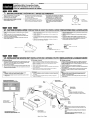
Owner’s manual
Mode d’emploi
Manual de instrucciones
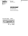
DXZ445
AM/FM CD PLAYER
•
RADIO AM/FM-LECTEUR CD
•
RADIO-REPRODUCTOR AM/FM DE DISCOS COMPACTOS
English
Thank you for purchasing this Clarion product.
Please read this owner’s manual in its entirety before operating this equipment.
After reading this manual, be sure to keep it in a handy place (e.g., glove compartment).
Check the contents of the enclosed warranty card and keep it carefully with this manual.
This manual includes the operating procedures of the CD changer and TV tuner connected via the
CeNET cable. The CD changer and TV tuner have their own manuals, but no explanations for operating them are described.
Contents
1. FEATURES ...................................................................................................................................... 2
2. PRECAUTIONS ............................................................................................................................... 3
Handling Compact Discs ................................................................................................................. 4
3. CONTROLS ..................................................................................................................................... 5
4. NOMENCLATURE .......................................................................................................................... 6
Names of the Buttons and their Functions ...................................................................................... 6
Major button operations when external equipment is connected to this unit ................................... 6
Display Items ................................................................................................................................... 8
LCD Screen ..................................................................................................................................... 8
5. DCP ................................................................................................................................................. 9
6. REMOTE CONTROL ..................................................................................................................... 10
Inserting the Batteries ................................................................................................................... 10
Functions of Remote Control Unit Buttons .................................................................................... 11
7. OPERATIONS ............................................................................................................................... 12
Basic Operations ........................................................................................................................... 12
Radio Operations ........................................................................................................................... 14
CD Operations ............................................................................................................................... 16
Operations Common to Each Mode .............................................................................................. 17
8. OPERATIONS OF ACCESSORIES .............................................................................................. 20
CD Changer Operations ................................................................................................................ 20
TV Operations ................................................................................................................................ 22
9. IN CASE OF DIFFICULTY ............................................................................................................ 24
10. ERROR DISPLAYS ....................................................................................................................... 25
11. SPECIFICATIONS ......................................................................................................................... 26
1. FEATURES
•
•
•
•
•
•
•
•
2
Visible Blue Negative LCD and White Illuminated Buttons
Aluminum Detachable Faceplate
Z-ENHANCER PLUS with 2 Band P.EQ for Sound Creation
MAGNA BASS EX for Dynamic Bass Tuning
4ch RCA Output and 2ch AUX Input with 3 Level Adjustments
CeNET with Balanced Audio Line Transmission and Dynamic Noise Canceling
Sirius Control
IR Remote Control Included
DXZ445
1. When the inside of the car is very cold and the
player is used soon after switching on the
heater moisture may form on the disc or the
optical parts of the player and proper playback
may not be possible. If moisture forms on the
disc, wipe it off with a soft cloth. If moisture
forms on the optical parts of the player, do not
use the player for about one hour. The
condensation will disappear naturally allowing
normal operation.
This equipment has been tested and found to
comply with the limits for a Class B digital device,
pursuant to Part 15 of the FCC Rules.
These limits are designed to provide reasonable
protection against harmful interference in a
residential installation.
This equipment generates, uses, and can radiate
radio frequency energy and, if not installed and
used in accordance with the instructions, may
cause harmful interference to radio
communications. However, there is no guarantee
that interference will not occur in a particular
installation.
If this equipment does cause harmful interference
to radio or television reception, which can be
determined by turning the equipment off and on,
the user is encouraged to consult the dealer or
an experienced radio/TV technician for help.
2. Driving on extremely bumpy roads which
cause severe vibration may cause the sound
to skip.
3. This unit uses a precision mechanism. Even in
the event that trouble arises, never open the
case, disassemble the unit, or lubricate the
rotating parts.
CAUTION
USE OF CONTROLS, ADJUSTMENTS, OR
PERFORMANCE OF PROCEDURES OTHER
THAN THOSE SPECIFIED HEREIN, MAY
RESULT IN HAZARDOUS RADIATION
EXPOSURE.
THE COMPACT DISC PLAYER and MINI DISC
PLAYER SHOULD NOT BE ADJUSTED OR
REPAIRED BY ANYONE EXCEPT PROPERLY
QUALIFIED SERVICE PERSONNEL.
CHANGES OR MODIFICATIONS NOT
EXPRESSLY APPROVED BY THE
MANUFACTURER FOR COMPLIANCE COULD
VOID THE USER’S AUTHORITY TO OPERATE
THE EQUIPMENT.
INFORMATION FOR USERS:.
CHANGES OR MODIFICATIONS TO THIS
PRODUCT NOT APPROVED BY THE
MANUFACTURER WILL VOID THE WARRANTY
AND WILL VIOLATE FCC APPROVAL.
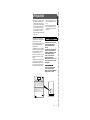
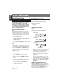
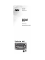
MODEL
12V
GROUND
AM 530 -1710kHz /FM 87.9 -107.9MHz
TH I S DEVICE COMPLIES WITH PART 15 OF THE FCC RULES.
OPERATION IS SUBJECT TO THE FOLLOWING TWO CONDITIONS:
(1) THIS DEVICE MAY NOT CAUSE HARMFUL INTERFERENCE, AND
(2) THIS DEVICE MUST ACCEPT ANY INTERFERENCE RECEIVED,
INCLUDING INTERFERENCE THAT MAY CAUSE UNDESIRED
OPERATION.
THIS PRODUCTION COMPLIES WITH DHHS RULES 21 CFR
SUBCHAPTER J APPLICABLE AT DATE OF MANUFACTURE.
CLARION CO.,LTD.
50 KAMITODA,TODA-SHI,SAITAMA-KEN,JAPAN
MANUFACTURED:
SERIAL No.
PE-
Clarion Co.,Ltd.
MADE IN
Bottom View of Source Unit
DXZ445
3
English
2. PRECAUTIONS
Handling Compact Discs
or
Do not play heart-shaped, octagonal, or other
specially shaped compact discs.
Some CDs recorded in CD-R/CD-RW mode
may not be usable.
Handling
• Compared to ordinary music CDs, CD-R and
CD-RW discs are both easily affected by high
temperature and humidity and some of CD-R
and CD-RW discs may not be played. Therefore,
do not leave them for a long time in the car.
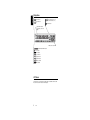
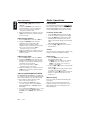
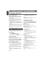
• New discs may have
Ball-point pen
some roughness
around the edges. If
Roughness
such discs are used,
the player may not
work or the sound
may skip. Use a ballpoint pen or the like
to remove any
roughness from the edge of the disc.
• Never stick labels on the surface of the compact
disc or mark the surface with a pencil or pen.
• Never play a compact disc with any
cellophane tape or other glue on it or with
peeling off marks. If you try to play such a
compact disc, you may not be able to get it
back out of the CD player or it may damage
the CD player.
• Do not use compact discs that have large
scratches, are misshapen, cracked, etc. Use of
such discs may cause misoperation or damage.
• To remove a compact disc from its storage case,
press down on the center of the case and lift the
disc out, holding it carefully by the edges.
• Do not use commercially available CD
protection sheets or discs equipped with
stabilizers, etc. These may damage the disc or
cause breakdown of the internal mechanism.
Storage
• Do not expose compact discs to direct sunlight
or any heat source.
• Do not expose compact discs to excess
humidity or dust.
• Do not expose compact discs to direct heat
from heaters.
Cleaning
• To remove fingermarks and dust, use a soft
cloth and wipe in a straight line from the center
of the compact disc to the circumference.
• Do not use any solvents, such as commercially
available cleaners, anti-static spray, or thinner
to clean compact discs.
• After using special compact disc cleaner, let
the compact disc dry off well before playing it.
Be sure to unfold and read the next page. / Veuillez déplier et vous référer à la page suivante.
Cerciórese de desplegar y de leer la página siguiente.
DXZ445
4
English
Use only compact discs bearing the
mark.
English
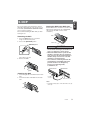
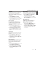
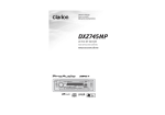
3.CONTROLS / LES COMMANDES / CONTROLES
Source unit / Appareil pilote / Unidad fuente
Français Español
[CD SLOT]
[ROTARY]
[Q]
[RELEASE]
[Z+]
[ISR]
[DISP]
[FNC]
[A-M]
[BND]
[a], [d]
[DIRECT]
[
]
[DN], [UP]
[SCN]
[RPT]
[RDM]
Note: Be sure to unfold this page and refer to the front diagrams as you read each chapter.
Remarque: Veuillez déplier cette page et vous référer aux schémas quand vous lisez chaque chapitre.
Nota: Cuando lea los capítulos, despliegue esta página y consulte los diagramas.
5
DXZ445
[T]
[P/A]
English
4. NOMENCLATURE
Note:
• Be sure to read this chapter referring to the front diagrams of chapter “3. CONTROLS” on page 5 (unfold).
Names of the Buttons and their Functions
[RELEASE] button
[DIRECT] buttons
• Deeply push in [RELEASE] button to unlock
the DCP.
• Store a station into memory or recall it
directly while in the radio mode.
[ROTARY] knob
[RDM] button
• Adjust the volume by turning the knob
clockwise or counterclockwise.
• Use the knob to perform various settings.
• Perform random play while in the CD mode.
[CD SLOT]
[SCN] button
• CD insertion slot.
[RPT] button
• Repeat play while in the CD mode.
[Q] button
• Perform scan play for 10 seconds of each
track while in the CD mode.
• Eject a CD when it is loaded into the unit.
[
[Z+] button
• Play or pause a CD while in the CD mode.
• Use the button to select one of the 3 types of
sound characteristics already stored in
memory.
[a], [d] buttons
[ISR] button
• Recall ISR radio station in memory.
• Press and hold for 2 seconds or longer: Store
current station into ISR memory (radio mode
only).
] button
• Select a station while in the radio mode or
select a track when listening to a CD. These
buttons are used to make various settings.
• Press and hold the button for 1 second or
longer to switch the fast-forward/fastbackward.
[BND] button
• Switch the display indication (Main display,
Sub display, Clock display).
• Switch the band, or seek tuning or manual
tuning while in the radio mode.
• Play a first track while in the CD mode.
[T] button
[A-M] button
• Use the button to input a title in the Tuner, CD
mode.
• Press and hold the button for 1 second or
longer to enter the adjust mode.
• Use the button to switch to the audio mode
(bass/treble, balance/fader Z-Enhancer Plus,
Magna Bass Extended adjustment)
[FNC] button
[P/A] button
• Press the button to turn on the power.
Press and hold the button for 1 second or
longer to turn off the power.
• Switches the operation mode among the
radio mode, etc.
[DISP] button
• Perform preset scan while in the radio mode.
When the button is pressed and held, auto
store is performed.
[UP], [DN] buttons
• Select the disc.
Major button operations when external equipment is
connected to this unit
● When the CD/DVD changer is
connected
For details, see the section “CD changer
operations”. For the DVD changer, refer to
the Owner’s Manual provided with the
DVD changer.
6
DXZ445
[DISP] button
• When the button is pressed and held,
switches the user titles or track titles, etc.
while in the CD changer mode.
Major button operations when external equipment is connected to this unit
• Use the button to input a title in the CD
changer mode.
• Use the button to scroll the title during CDtext play.
[UP], [DN] buttons
• Select the disc.
[RDM] button
• Perform random play. Also perform disc
random play when the button is pressed and
held.
[RPT] button
English
[T] button
● When the Sirius Satellite
Radio is connected
For details, refer to the Owner’s Manual
provided with the Sirius Satellite Radio.
[FNC] button
• Press the button to switch the operation
mode among the SIRIUS mode, etc.
[
] button
• Performs category scan while in the SIRIUS
mode. When the button is pressed and held,
preset scan is performed.
• Perform repeat play. When this button is
pressed and held, disc repeat play is
performed.
[DIRECT] buttons
[BND] button
[a], [d] button
• Move the next disc in increasing order.
• Press the button to select a station.
• Stores a station into memory or recall it
directly while in the SIRIUS mode.
[SCN] button
• Perform scan play for 10 seconds of each
track. Disc scan play is performed when the
button is pressed and held.
[
] button
• Play or pause a CD or DVD.
[a], [d] buttons
• Select a track when listening to a disc.
• Press and hold the button for 1 second or
longer to switch the fast-forward/fastbackward.
● When the TV is connected
For details, see the section “TV
operations”.
[P/A] button
• Perform preset scan while in the TV mode.
When the button is pressed and held, auto
store is performed.
[
] button
• Switch the TV picture mode or VTR (external)
picture mode.
[DIRECT] buttons
• Store a station into memory or recall it
directly.
[a], [d] buttons
• Select a station.
[BND] button
• Switch the band.
• When the button is pressed and held, switch
seek tuning or manual mode.
What is Sirius Satellite Radio?
Sirius is radio the way it was meant to be: Up
to 100 new channels of digital quality
programming delivered to listeners coast to
coast via satellite. That means 50 channels of
completely commercial-free music. Plus up to
50 more channels of news, sports, and
entertainment from names like CNBC,
Discovery, SCI-FI Channel, A&E, House of
Blues, E!, NPR, Speedvision and ESPN.
Sirius is live, dynamic entertainment,
completely focused on listeners. Every minute
of every day of every week will be different. All
50 commercial-free music channels are created
in-house and hosted by DJs who know and
love the music. Do you like Reggae? How
about Classic Rock or New Rock? Sirius has
an array of choices spanning a vast range of
musical tastes including the hits of the 50’s,
60’s, 70’s, & 80’s as well as Jazz, Country,
Blues, Pop, Rap, R&B, Bluegrass, Alternative,
Classical, Heavy Metal, Dance and many
others...
From its state-of-the-art, digital broadcasting
facility in Rockefeller Center, New York City,
Sirius will deliver the broadest, deepest mix of
radio entertainment from coast to coast.
Sirius will bring you music and entertainment
programming that is simply not available on
traditional radio in any market across the
country. It’s radio like you’ve never heard
before.
So Get Sirius and Listen Up! For more
information, visit siriusradio.com.
DXZ445
7
Display Items
English
: Enter indication
: Preset channel indication (1 to 6)
Disc number indication (1 to 12)
: Manual indication
: SIRIUS indication
Operation status indication
Titles, frequency, clock, etc. are
displays.
Z-Enhancer Plus indication
: MAGNA BASS EXTEND indication
: Stereo indication
: Disc indication
: Scan indication
: Repeat indication
: Random indication
: Category indication
: Mute indication
LCD Screen
In extreme cold, the screen movement may slow down and the screen may darken, but this is normal.
The screen will recover when it returns to normal temperature.
8
DXZ445
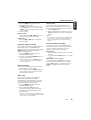
The control panel can be detached to prevent
theft. When detaching the control panel, store it
in the DCP (DETACHABLE CONTROL PANEL)
case to prevent scratches.
We recommend taking the DCP with you when
leaving the car.
Storing the DCP in the DCP Case
Hold the DCP, in the orientation as shown in the
figure below, and put it into the supplied DCP
case. (Ensure the DCP is in the correct
orientation.)
DCP
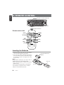
Removing the DCP
1. Press the [FNC] button for 1 second or
longer to switch off the power.
2. Press in the [RELEASE] button.
DCP case
[RELEASE] button
CAUTION
• The DCP can easily be damaged by
shocks. After removing it, be careful not to
drop it or subject it to strong shocks.
• When the Release button is pressed and
the DCP is unlocked, the car’s vibrations
may cause it to fall. To prevent damage to
the DCP, always store it in its case after
detaching it. (ee figure below.)
• The connector connecting the main unit
and the DCP is an extremely important
part. Be careful not to damage it by
pressing on it with fingernails,
screwdrivers, etc.
The DCP is unlocked
3. Remove the DCP.
DCP Rear Panel
Main Unit Front
DCP
Attaching the DCP
1. Insert the right side of the DCP into the main
unit.
2. Insert the left side of the DCP into the main
unit.
DCP
connector
Main unit connector
Note:
• If the DCP is dirty, wipe off the dirt with a soft, dry
cloth only.
2.
DCP
1.
DXZ445
9
English
5. DCP
English
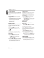
6. REMOTE CONTROL
Receiver for remote control unit
Operating range: 30˚ in all directions
Signal transmitter
Remote control unit
[FUNC]
[
],[
[2-ZONE]
[
]
]
[ ],[ ]
[BAND]
[ISR]
[MUTE]
[DISP]
[SCN]
[RDM]
[RPT]
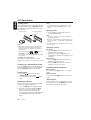
Inserting the Batteries
1. Turn the remote control unit over, then slide the
rear cover in the direction of the arrow.
2. Insert the AA (SUM-3, IECR-6/1.5V) batteries
that came with the remote control unit facing in
the directions shown in the figure, then close
the rear cover.
Notes:
Using batteries improperly can cause them to
explode. Take note of the following points:
• When replacing batteries, replace both batteries
with new ones.
• Do not short-circuit, disassemble or heat batteries.
• Do not dispose of batteries into fire or flames.
• Dispose of spent batteries properly.
10
DXZ445
AA (SUM-3, IECR-6/1.5V)
Batteries
Rear cover
Rear side
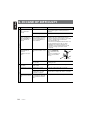
Mode
Radio / SIRIUS
CD changer
DVD changer
CD
Button
TV
[FUNC]
Switches among radio, SIRIUS tuner, CD, CD changer, DVD changer, TV and AUX.
[BAND]
Switches reception
band.
Plays the first track.
Top play.
Moves the next disc
in increasing order.
Switches reception
band.
[
],[
]
Increases and decreases volume (in all modes).
[
],[
]
Moves preset
channels up and
down.
Moves tracks up and down.
When pressed and held for 1 second:
Fast-forward/fast-backward.
Moves preset
channels up and
down.
No function.
Switches between playback and pause.
No function.
[
]
[MUTE]
[ISR]
English
Functions of Remote Control Unit Buttons
Turns mute on and off.
Recalls ISR radio station in memory.
Press and hold for 2 seconds or longer: Stores current station into ISR memory
(radio mode only).
[DISP]
Switches among main display, sub display, clock display.
[SCN]
Preset scan.
When pressed and
held for 2 seconds:
Auto store.
Scan play.
Scan play.
When pressed and
held for 1 second:
Disc scan play.
Preset scan.
When pressed and
held for 2 seconds:
Auto store.
[RPT]
No function.
Repeat play.
Repeat play.
When pressed and
held for 1 second:
Disc repeat play.
No function.
[RDM]
No function.
Random play.
Random play.
When pressed and
held for 1 second:
Disc random play.
Switches between TV
and VTR.
Some of the corresponding buttons on the main unit and remote control unit have different functions.
[2-ZONE] button is not available.
DXZ445
11
English
7. OPERATIONS
Basic Operations
Note:Be sure to read this chapter referring to the front diagrams of
chapter “3. CONTROLS” on page 5 (unfold).
CAUTION
Be sure to lower the volume before
switching off the unit power or the ignition
key. The unit remembers its last volume
setting. If you switch the power off with the
volume up, when you switch the power back
on, the sudden loud volume may hurt your
hearing and damage the unit.
Turning on/off the power
Note:
• Be careful about using this unit for a long time
without running the engine. If you drain the car’s
battery too far, you may not be able to start the
engine and this can reduce the service life of the
battery.
1. Press the [FNC] button.
2. The illumination and display on the unit light
up. The unit automatically remembers its last
operation mode and will automatically switch
to display that mode.
3. Press and hold the [FNC] button for 1 second
or longer to turn off the power for the unit.
Note:
• System check
The first time this unit is turned on after the wire
connections are completed, it must be checked
what equipment is connected. When the power is
turned on, “SYSTEM” and “PUSH PWR” appear
in the display alternately, so press the [FNC]
button. The system check starts within the unit.
When the system check is complete, press the
[FNC] button again.
Selecting a mode
1. Press the [FNC] button to change the
operation mode.
2. Each time you press the [FNC] button, the
operation mode changes in the following
order:
Radio mode ➜ SIRIUS mode ➜ CD mode ➜
CD changer mode ➜ DVD changer mode ➜
TV mode ➜ AUX mode ➜ Radio mode...
External equipment not connected with
CeNET is not displayed.
Adjusting the volume
Turning the [ROTARY] knob clockwise increases
the volume; turning it counterclockwise
decreases the volume.
The volume level is from 0 (minimum) to 33
(maximum).
Switching the display
Press the [DISP] button to select the desired
display.
Each time you press the [DISP] button, the
display switches in the following order:
Main display
Sub display
Clock display
Main display
Once selected, the preferred display becomes
the display default. When a function
adjustment such as volume is made, the
screen will momentarily switch to that
function’s display, then revert back to the
preferred display several seconds after the
adjustment.
When you have entered a title in a CD, it
appears in the sub display. If you have not
entered a title, “NO TITLE” appears in the title
display instead. For information on how to
enter a title, refer to the subsection “Entering
titles” in section “Operations Common to
Each Mode”.
Setting the Z-Enhancer Plus
This unit are provided with 3 types of sound tone
effects stored in memory. Select the one you prefer.
The factory default setting is “Z+ OFF”.
Each time you press the [Z+] button, the tone
effect changes in the following order:
12
DXZ445
Basic Operations
Adjusting the Z-Enhancer Plus
1. Press the [Z+] button and select the ZEnhancer Plus mode to adjust.
2. Press the [A-M] button and turning the
[ROTARY] knob clockwise adjusts in the +
direction; turning it counterclockwise adjusts
in the – direction.
●When “B-BST 0” is selected, you can adjust
the bass in the range of –3 to 3.
●When “IMPACT 0” is selected, you can adjust
the bass and treble in the range of –3 to 3.
●When “EXCITE 0” is selected, you can adjust
the bass and treble in the range of –3 to 3.
Press and hold the [Z+] button for 2 seconds
or longer to change to the “CUSTOM” mode.
Bass/treble characteristics become flat and the
indication “Z+ FLAT” is shown in the display.
Press the [Z+] button again to change to the
“Z+ OFF” mode.
Adjusting the tone
Press the [A-M] button and select the item to
adjust. Each time you press the [A-M] button,
the item changes as following order:
● When “B-BOOST” is set
“S-VOL 0” ➜ “B-BOOST” ➜ “BAL 0” ➜
“FAD 0” ➜ Last function mode.
● When “IMPACT” is set
“S-VOL 0” ➜ “IMPACT” ➜ “BAL 0” ➜
“FAD 0” ➜ Last function mode.
● When “EXCITE” is set
“S-VOL 0” ➜ “EXCITE” ➜ “BAL 0” ➜
“FAD 0” ➜ Last function mode.
● When “CUSTOM” is set
“S-VOL 0” ➜ “BASS” ➜ “TREBLE” ➜
“BAL 0” ➜ “FAD 0” ➜ Last function mode.
● When “Z+ OFF” is set
“S-VOL 0” ➜ “BAL 0” ➜ “FAD 0” ➜ Last
function mode.
Adjusting the Subwoofer
When you default select one of mode (LPF50,
LPF80, LPF120).
1. Press the [A-M] button and select
“S-VOL 0”.
2. Turning the [ROTARY] knob clockwise or
counterclockwise to adjust the subwoofer
volume.
The factory default setting is “S-VOL 0”.
(Adjustment range: –6 to +6)
3. When the adjustment is complete, press the
[A-M] button several times until the function
mode is reached.
Adjusting the bass (Gain,
Frequency, Q-curve)
This adjustment can be performed when the
Z-Enhancer Plus is set to “CUSTOM”.
1. Press the [A-M] button and select “BASS”.
2. Turning the [ROTARY] knob clockwise
emphasizes the bass; turning it
counterclockwise attenuates the bass.
The factory default setting is “B<G 0>”.
(Adjustment range: –6 to +6)
3. Press the [a] or [d] button to select
“B<F 60>”.
Turning the [ROTARY] knob clockwise or
counterclockwise to select the frequency.
The factory default setting is “B<F 60>”.
(Adjustment 60/100/200 Hz)
4. Press the [a] or [d] button to select
“B<Q 1>”.
Turning the [ROTARY] knob clockwise or
counterclockwise to select the Q-curve.
The factory default setting is “B<Q 1>”.
(Adjustment 1/1.25/1.5/2)
5. When the adjustment is complete, press the
[A-M] button several times until the function
mode is reached.
Adjusting the treble (Gain,
Frequency)
This adjustment can be performed when the ZEnhancer Plus is set to “CUSTOM”.
1. Press the [A-M] button and select “TREBLE”.
2. Turning the [ROTARY] knob clockwise
emphasizes the treble; turning it
counterclockwise attenuates the treble.
The factory default setting is “T<G 0>”.
(Adjustment range: –6 to +6)
If sub-woofer is effective “S-VOL 0” can be selected.
DXZ445
13
English
“Z+ OFF” ➜ “B-BOOST” ➜ “IMPACT” ➜
“EXCITE” ➜ “CUSTOM” ➜ “Z+ OFF” ...
• B-BOOST
: bass emphasized
• IMPACT
: bass and treble
emphasized
• EXCITE
: bass and treble emphasized mid de-emphasized
• CUSTOM
: user custom
• Z+ OFF
: no sound effect
English
Basic Operations
Radio Operations
3. Press the [a] or [d] button to select
“T<F 10>”.
Turning the [ROTARY] knob clockwise or
counterclockwise to select the frequency.
FM reception
The factory default setting is “T<F 10>”.
(Adjustment 10 kHz/15 kHz)
4. When the adjustment is complete, press the
[A-M] button several times until the function
mode is reached.
Adjusting the balance
1. Press the [A-M] button and select “BAL 0”.
2. Turning the [ROTARY] knob clockwise
emphasizes the sound from the right
speaker; turning it counterclockwise
emphasizes the sound from the left speaker.
®
For enhanced FM performance the
tuner includes signal actuated stereo control,
Enhanced Multi AGC, Impulse noise reduction
curcuits and Multipath noise reduction circuits.
Listening to the radio
1. Press the [FNC] button and select the radio
mode. The frequency appears in the display.
2. Press the [BND] button and select the radio
band. Each time the button is pressed, the
radio reception band changes in the following
order:
FM1 ➜ FM2 ➜ FM3 ➜ AM ➜ FM1...
3. Press the [a] or [d] button to tune in the
desired station.
The factory default setting is “BAL 0”.
(Adjustment range: L13 to R13)
3. When the adjustment is complete, press the
[A-M] button several times until the function
mode is reached.
Tuning
Adjusting the fader
Seek tuning
1. Press the [A-M] button and select “FAD 0”.
2. Turning the [ROTARY] knob clockwise emphasizes the sound from the front speakers;
turning it counterclockwise emphasizes the
sound from the rear speakers.
1. Press the [BND] button and select the
desired band (FM or AM).
The factory default setting is “FAD 0”.
(Adjustment range: F12 to R12)
3. When the adjustment is complete, press the
[A-M] button several times until the function
mode is reached.
Adjusting MAGNA BASS EXTEND
The MAGNA BASS EXTEND does not adjust the
low sound area like the normal sound adjustment
function, but emphasizes the deep bass sound
area to provide you with a dynamic sound.
The factory default setting is off.
1. Press and hold the [A-M] button for 1
second or longer to turn on the MAGNA
BASS EXTEND effect. “M-B EX” lights in
the display.
2. Press and hold the [A-M] button for 1 second
or longer to turn off the MAGNA BASS
EXTEND effect. “M-B EX” goes off from the
display.
14
DXZ445
There are 3 types of tuning mode available, seek
tuning, manual tuning and preset tuning.
If “MANU” is lit in the display, press and hold
the [BND] button for 1 second or longer.
“MANU” in the display goes off and seek
tuning is now available.
2. Press the [a] or [d] button to automatically
seek a station.
When the [d] button is pressed, the station
is sought in the direction of higher
frequencies; if the [a] button is pressed, the
station is sought in the direction of lower
frequencies.
Manual tuning
There are 2 ways available: Quick tuning and
step tuning.
When you are in the step tuning mode, the
frequency changes one step at a time. In the
quick tuning mode, you can quickly tune the
desired frequency.
Radio Operations
If “MANU” is not lit in the display, press and
hold the [BND] button for 1 second or longer.
“MANU” is lit in the display and manual tuning
is now available.
2. Tune in a station.
● Quick tuning:
Press and hold the [a] or [d] button for 1
second or longer to tune in a station.
● Step tuning:
Press the [a] or [d] button to manually
tune in a station.
Recalling a preset station
A total of 24 preset positions (6-FM1, 6-FM2, 6FM3, 6-AM) exist to store individual radio
stations in memory. Pressing the corresponding
[DIRECT] button recalls the stored radio
frequency automatically.
1. Press the [BND] button and select the
desired band (FM or AM).
2. Press the corresponding [DIRECT] button to
recall the stored station.
Press and hold one of the [DIRECT] buttons
for 2 seconds or longer to store that station
into preset memory.
Manual memory
1. Select the desired station with seek tuning,
manual tuning or preset tuning.
2. Press and hold one of the [DIRECT] buttons
for 2 seconds or longer to store the current
station into preset memory.
Preset scan
Preset scan receives the stations stored in
preset memory in order. This function is useful
when searching for a desired station in memory.
1. Press the [P/A] button.
2. When a desired station is tuned in, press the
[P/A] button again to continue receiving that
station.
Note:
• Be careful not to press and hold the [P/A] button
for 2 seconds or longer, otherwise the auto store
function is engaged and the unit starts storing
stations.
Instant station recall (ISR)
Instant station recall is a special radio preset
that instantly accesses a favorite radio station at
a touch of a button. The ISR function even
operates with the unit in other modes.
●ISR memory
1. Select the station that you wish to store in ISR
memory.
2. Press and hold the [ISR] button for 2 seconds
or longer.
●Recalling a station with ISR
In any mode, press the [ISR] button to turn on
the radio function and tune the selected radio
station. “ISR” appears in the display. Press the
[ISR] button again to return to the previous
mode.
Auto store
Auto store is a function for storing up to 6
stations that are automatically tuned in
sequentially. If 6 receivable stations cannot be
received, a previously stored station remains
unoverwritten at the memory position.
1. Press the [BND] button and select the
desired band (FM or AM).
2. Press and hold the [P/A] button for 2
seconds or longer. The stations with good
reception are stored automatically to the
preset channels.
If auto store is performed in the FM bands, the
stations are stored in FM3 even if FM1 or FM2
was chosen for storing stations.
DXZ445
15
English
1. Press the [BND] button and select the
desired band (FM or AM).
CD Operations
English
Loading a CD
Insert a CD into the centre of the CD SLOT with
the labeled side facing up. “LOADING” appears
in the display, the CD enters into the slot, and
the play starts.
For CD (12 cm)
For single CD (8 cm)
CD SLOT
Notes:
• Never insert foreign objects into the CD SLOT.
• If the CD is not inserted easily, there may be
another CD in the mechanism or the unit may
require service.
• Discs not bearing the
or
mark and
CD-ROMs cannot be played by this unit.
• Some CDs recorded in CD-R/CD-RW mode may
not be usable.
Loading 8 cm compact discs
No adapter is required to play an 8 cm CD.
Insert the 8 cm CD into the centre of the insertion
slot.
Listening to a CD already inserted
Press the [FNC] button to select the CD mode.
Play starts automatically. If no CD is loaded in
the unit, “NO DISC” appears in the display.
Pausing play
1. Press the [
] button to pause play.
“PAUSE” appears in the display.
] button
2. To resume CD play, press the [
again.
Note:
• If the CD playing is not a CD-text CD or no user
title has been input, “NO TITLE” appears in the
display.
Ejecting a CD
1. Press the [Q] to eject the CD. Take it out
from the ejected position.
Note:
• If you force a CD into before auto reloading, this
can damage the CD.
If a CD (12 cm) is left in the ejected position for 15
seconds, the CD is automatically reloaded (Auto
reload).
8 cm CDs are not auto reloaded. Be sure to remove
it when ejected.
Selecting a track
● Track-up
1. Press the [d] button to move ahead to the
beginning of the next track.
2. Each time you press the [d] button, the
track advances ahead to the beginning of the
next track.
● Track-down
1. Press the [a] button to move back to the
beginning of the current track.
2. Press the [a] button twice to move to the
beginning of the previous track.
Fast-forward/fast-backward
● Fast-forward
Press and hold the [d] button for 1 second or
longer.
● Fast-backward
Press and hold the [a] button for 1 second or
longer.
Top function
Displaying CD titles
This unit can display title data for CD-text CDs
and user titles input with this unit.
1. Press the [DISP] button to display the title.
2. Each time you press and hold the [DISP]
button for 1 second or longer, the title
display changes in the following order:
User title (disc) ➜ CD-text title (disc) ➜ Artist
name ➜ CD-text title (track) ➜ User title
(disc)...
16
DXZ445
The top function resets the CD player to the first
track of the disc. Press the [BND] button to play
the first track (track No. 1) on the disc.
CD Operations
The scan play locates and plays the first 10
seconds of each track on a disc automatically.
This function continues on the disc until it is
cancelled.
The scan play is useful when you want to select a
desired track.
1. Press the [SCN] button to start scan play.
“SCN” lights in the display.
2. To cancel the scan play, press the [SCN]
button again. “SCN” goes off from the
display and the current track continues to
play.
Repeat play
The repeat play continuously plays the current
track. This function continues automatically until
it is cancelled.
1. Press the [RPT] button. “RPT” lights in the
display and the current track is repeated.
2. To cancel the repeat play, press the [RPT]
button again. “RPT” goes off from the display
and normal play resumes.
Random play
The random play selects and plays individual
tracks on a disc in no particular order. This
function continues automatically until it is
cancelled.
1. Press the [RDM] button. “RDM” lights in the
display, an individual track is selected
randomly and play begins.
2. To cancel the random play, press the [RDM]
button again. “RDM” goes off from the display
and normal play resumes.
Turning the screen saver function
on or off
This unit is provided with the screen saver
function which allows you to show various kinds
of patterns and characters in the Operation
Status indication area of the display in a random
order. You can turn on and off this function.
If the button operation is performed with the
screen saver function on, the operation display
corresponding to the button operation is shown
for about 30 seconds and the display returns to
the screen saver display.
The factory default setting is “SS”.
1. Press and hold the [T] button for 1 second or
longer to switch to the adjustment selection
display.
2. Press the [a] or [d] button to select
“SCRN SVR”.
] button.
3. Press the [
4. Turn the [ROTARY] knob clockwise or
counterclockwise to select the setting. Each
time you turn the [ROTARY] knob, the setting
changes in the following order:
OFF ➜ SS ➜ MESSAGE
5. Press the [
] button to store the setting.
6. Press the [T] button to return to the previous
mode.
Entering MESSAGE INFORMATION
Message up to 30 characters long can be stored
in memory and displayed for any mode.
* The factory default setting is “WELCOME TO
CLARION”.
1. Press and hold the [T] button for 1 second or
longer to switch to the adjustment selection
display.
2. Press the [a] or [d] button to select
“INPUT”.
3. Press the [
] button.
4. Press the [BND] button to clear the old
message.
5. Press the [a] or [d] button to move the
cursor.
6. Press the [DISP] button to select a character.
Each time you press the [DISP] button, the
character changes in the following orders:
Numbers ➜ Symbols ➜ Capital letters ➜
Numbers…
DXZ445
17
English
Scan play
Operations Common to
Each Mode
Operations Common to Each Mode
English
7. Turn the [ROTARY] knob to select the
desired character.
8. Repeat step 5 to 7 to enter up to 30
characters for message.
9. Press and hold the [
] button for 2
seconds or longer to store the message in
memory and cancel input message.
10.Press the [T] button to return to the previous
mode.
Setting the method for title scroll
Set how to scroll in CD-TEXT.
The factory default setting is “ON”.
1. Press and hold the [T] button for 1 second or
longer to switch to the adjustment selection
display.
2. Press the [a] or [d] button to select
“SCROLL”.
3. Turn the [ROTARY] knob clockwise or
counterclockwise and select “ON” or “OFF”.
● ON:
To scroll automatically.
● OFF:
To scroll just 1 time when the title was
changed or the title key was pressed.
4. Press the [T] button to return to the previous
mode.
Dimmer control
You can set the dimmer control on or off.
Adjusting the display contrast
You can adjust the display contrast to match the
angle of installation of the unit.
The factory default setting is “5”. (Adjustment
level:1to 8)
1. Press and hold the [T] button for 1 second or
longer to switch to the adjustment selection
display.
2. Press the [a] or [d] button to select
“CONTRAST”.
3. Turn the [ROTARY] knob clockwise or
counterclockwise to adjust the contrast.
4. Press the [T] button to return to the previous
mode.
Setting LOW PASS FILTER
This function allows you to set the low-pass filter
sub-woofer output.
The factory default setting is “LPF 120”.
1. Press and hold the [T] button for 1 second or
longer to switch to the adjustment selection
display.
2. Press the [a] or [d] button to select “SW
LPF”.
3. Turn the [ROTARY] knob clockwise or
counterclockwise to select the setting. Each
time you turn the [ROTARY] knob, the setting
changes in the following order:
REAR ➜ LPF 50 ➜ LPF 80 ➜ LPF 120
4. Press the [T] button to return to the previous
mode.
The factory default setting is “ON”.
1. Press and hold the [T] button for 1 second or
longer to switch to the adjustment selection
display.
2. Press the [a] or [d] button to select
“DIMMER”.
3. Turn the [ROTARY] knob clockwise to “ON”
or counterclockwise to “OFF”.
4. Press the [T] button to return to the previous
mode.
18
DXZ445
Selecting AUX IN sensitivity
Make the following settings to select the
sensitivity when sounds from external devices
connected to this unit are difficult to hear even
after adjusting the volume.
The factory default setting is “MID”.
1. Press and hold the [T] button for 1 second or
longer to switch to the adjustment selection
display.
2. Press the [a] or [d] button to select “AUX
SENS”.
3. Turn the [ROTARY] knob clockwise or
counterclockwise as needed and select from
“HIGH”, “MID” or “LOW”.
4. Press the [T] button to return to the previous
mode.
Operations Common to Each Mode
1. Press and hold the [T] button for 1 second or
longer to switch to the adjustment selection
display.
2. Press the [a] or [d] button to select
“CLOCK”.
3. Press the [
] button.
4. Press the [a] or [d] button to select the
hour or the minute.
5. Turn the [ROTARY] knob clockwise or
counterclockwise to set the correct time.
The clock is displayed in 12-hour format.
6. Press the [
] button to store the time into
memory.
7. Press the [T] button to return to the previous
mode.
Note:
• You cannot set the clock when it is displayed with
only the ignition on. If you drain or remove the
car’s battery or take out this unit, the clock is
reset. While setting the clock, if another button or
operation is selected, the clock set mode is
canceled.
Entering titles
Titles up to 8 characters long can be stored in
memory and displayed for CD, CD changer and
TV stations. The number of titles that can be
entered for each mode are as follows.
Mode
CD mode
TV mode
TUNER mode
Number of titles
50 titles
20 titles
30 titles
CD changer mode
DCZ625 connected
CDC655Tz connected
CDC1255z connected
Number of titles
100 titles
100 titles
50 titles
6. Press the [DISP] button to select a character.
Each time you press the [DISP] button, the
character changes in the following order:
Numbers ➜ Symbols ➜ Capital letters ➜
Numbers...
7. Turn the [ROTARY] knob to select the
desired character.
8. Repeat steps 5 to 7 to enter up to 8
characters for the title.
] button for 2
9. Press and hold the [
seconds or longer to store the title into
memory and cancel title input mode.
Clearing titles
1. Select and play a CD in the CD changer or
tune in to a TV station or TUNER for which
you want to clear the title.
2. Press the [DISP] button and display the sub.
3. Press the [T] button.
The display switches to the title input display.
4. Press the [BND] button.
5. Press and hold the [
] button for 2
seconds or longer to clear the title and
cancel title input mode.
AUX function
This system has an external input jack so you
can listen to sounds and music from external
devices connected to this unit.
1. Press the [FNC] button to select the mode
you want to enter a title (TUNER, CD, CD
changer or TV).
2. Select and play a CD in the CD changer or
tune in to a TV station or TUNER for which
you want to enter the title.
3. Press the [DISP] button and display the sub.
4. Press the [T] button. The cursor position
flashes.
5. Press the [a] or [d] button to move the
cursor.
DXZ445
19
English
Setting the clock
English
8. OPERATIONS OF ACCESSORIES
CD Changer Operations
CD changer functions
When an optional CD changer is connected
through the CeNET cable, this unit controls all
CD changer functions. This unit can control a
total of 2 changers.
Press the [FNC] button and select the CD
changer mode to start play. If 2 CD changers
are connected, press the [FNC] button to select
the CD changer for play.
If “NO MAG” appears in the display, insert the
magazine into the CD changer. “DISC CHK” appears
in the display while the player loads (checks) the
magazine.
If “NO DISC” appears in the display, eject the
magazine and insert discs into each slot. Then,
reinsert the magazine back into the CD changer.
Note:
• Some CDs recorded in CD-R/CD-RW mode may
not be usable.
CAUTION
CD-ROM discs cannot be played from every
CD changer, it’s depended on the model.
Pausing play
1. Press the [
] button to pause play.
“PAUSE” appears in the display.
2. To resume play, press the [
] button again.
Displaying CD titles
This unit can display title data for CD-text CDs
and user titles input with this unit.
Title data for CD-text CDs can be displayed with
this unit only when it is connected to CDC655Tz.
●When connected to DCZ625 or CDC1255z.
Press the [DISP] button to display the title.
●When connected to CDC655Tz
1. Press the [DISP] button to display the title.
2. Each time you press and hold the [DISP]
button for 1 second or longer, the title display
changes in the following order:
User title (disc) ➜ CD-text title (disc) ➜ Artist
name ➜ CD-text title (track) ➜ User title (disc)…
Notes:
• If the CD playing is not a CD-text CD or no user
title has been input, “NO TITLE” appears in the
display.
20
DXZ445
• If a CD-text CD is not input its disc title or a track
title, “NO TITLE” appears in the display.
Note:
• If an MD is not input its disc title or a track title,
“NO TITLE” appears in the display.
Procedure to scroll a title
Set “SCROLL” to “ON” or “OFF”.
(The factory default setting is “ON”. Refer to the
subsection “Turning the screen saver function
on or off” in section “Operation common to
each mode”.)
● When set to “ON”
The title is automatically kept scrolling.
● When set to “OFF”
To scroll just 1 time when the title was changed
or the [T] button was pressed.
Selecting a CD
1. Press the [UP] or [DN] button to select the
desired disc.
If a CD is not loaded in a slot of magazine,
pressing the [UP] or [DN] buton can not work.
Selecting a track
● Track-up
1. Press the [d] button to move ahead to the
beginning of the next track.
2. Each time you press the [d] button, the
track advances ahead to the beginning of the
next track.
● Track-down
1. Press the [a] button to move back to the
beginning of the current track.
2. Press the [a] button twice to move to the
beginning of the previous track.
Fast-forward/fast-backward
● Fast-forward
Press and hold the [d] button for 1 second or
longer.
● Fast-backward
Press and hold the [a] button for 1 second or
longer.
CD Changer Operations
Random play
Scan play locates and plays the first 10 seconds
of each track on a disc automatically. This
function continues on the disc until it is cancelled.
Random play selects and plays individual tracks
on the disc in no particular order. This function
continues automatically until it is cancelled.
1. Press the [RDM] button. “RDM” lights in the
display and random play begins.
2. To cancel random play, press the [RDM]
button again. “RDM” goes off from the display
and normal play resumes.
The scan play is useful when you want to select a
desired track.
1. Press the [SCN] button to start track
scanning. “SCN” lights in the display.
2. To cancel the scan play, press the [SCN]
button again. “SCN” goes off from the display
and the current track continues to play.
Disc scan play
Disc scan play locates and plays the first 10
seconds of the first track on each disc in the
currently selected CD changer. This function
continues automatically until it is cancelled.
Disc scan play is useful when you want to select a
desired CD.
1. Press and hold the [SCN] button for 1
second or longer. “DISC” and “SCN” light in
the display and disc scan play starts.
2. To cancel disc scan play, press the [SCN]
button again. “DISC” and “SCN” go off from
the display and the current track continues to
play.
Disc random play
The disc random play selects and plays
individual tracks or discs automatically in no
particular order. This function continues
automatically until it is cancelled.
1. Press and hold the [RDM] button for 1
second or longer. “DISC” and “RDM” light in
the display and disc random play starts.
2. To cancel disc random play, press the [RDM]
button again. “DISC” and “RDM” go off from
the display and normal play resumes from
the current track.
Repeat play
Repeat play continuously plays the current track.
This function continues automatically until it is
cancelled.
1. Press the [RPT] button. “RPT” lights in the
display and the current track is repeated.
2. To cancel repeat play, press the [RPT] button
again. “RPT” goes off from the display and
normal play resumes.
Disc repeat play
After all the tracks on the current disc have been
played, disc repeat play automatically replays
the current disc over from the first track. This
function continues automatically until it is
cancelled.
1. Press and hold the [RPT] button for 1 second
or longer. “DISC” and “RPT” light in the
display and disc repeat play starts.
2. To cancel disc repeat play, press the [RPT]
button again. “DISC” and “RPT” go off from
the display and normal play resumes on the
current track.
DXZ445
21
English
Scan play
TV Operations
English
TV tuner functions
Manual tuning
When an optional TV tuner is connected through
the CeNET cable, this unit controls all TV tuner
functions. To watch TV requires a TV tuner and
monitor.
There are 2 ways available: Quick tuning and
step tuning.
When you are in the step tuning mode, the
frequency changes one step at a time. In the
quick tuning mode, you can quickly tune the
desired frequency.
1. Press the [BND] button and select the
desired band (TV1 or TV2).
Watching a TV
1. Press the [FNC] button and select the TV
mode.
2. Press the [BND] button to select the desired
TV band (TV1 or TV2). Each time the button
is pressed, the input selection toggles
between TV1 and TV2.
3. Press the [a] or [d] button to tune in the
desired TV station.
Watching a video
The TV tuner has a VTR input terminal to which
1 external device can be connected. Connect a
12 V video cassette player (VCP) or video
cassette recorder (VCR) to the TV tuner input
terminal.
] button to select VTR.
1. Press the [
2. To return to the TV broadcast, press the
[
] button.
Tuning
There are 3 types of tuning mode available,
Seek tuning, manual tuning and preset tuning.
Seek tuning
1. Press the [BND] button and select the
desired TV band (TV1 or TV2).
If “MANU” is lit in the display, press and hold
the [BND] button for 1 second or longer.
“MANU” in the display goes off and seek
tuning is now available.
2. Press the [a] or [d] button to automatically
seek a station. Press the [d] button to automatically tune up the frequency band to the
next available TV station; press the [a]
button to automatically tune down.
22
DXZ445
If “MANU” is not lit in the display, press and
hold the [BND] button for 1 second or longer.
“MANU” lights in the display and manual
tuning is now available.
2. Tune in a station.
● Quick tuning:
Press and hold the [a] or [d] button for 1
second or longer to tune in a station.
● Step tuning:
Press the [a] or [d] button to manually
tune in a station.
Recalling a preset station
A total of 12 TV stations can be stored (6-TV1
and 6-TV2). This allows you to select your
favorite TV stations and store them in memory
for later recall.
1. Press the [BND] button and select the
desired TV band (TV1 or TV2).
2. To recall a stored TV station, press the
desired [DIRECT] button to select that
station.
Press and hold one of the [DIRECT] buttons
for 2 seconds or longer to store the current
station into preset memory.
Manual memory
1. Select the desired station with seek tuning,
manual tuning or preset tuning.
2. Press and hold one of [DIRECT] buttons for
2 seconds or longer to store the current
station into preset memory.
TV Operations
English
Auto store
Auto store selects 6 TV stations automatically
and stores each one into preset memory.
If there are not 6 stations with good reception,
stations previously stored in memory remain
and only the strong stations are stored into
memory.
1. Press the [BND] button and select the
desired TV band (TV1 or TV2).
2. Press and hold the [P/A] button for 2
seconds or longer. The stations with good
reception are stored automatically to the
preset channels.
Preset scan
Preset scan allows the user to view each preset
position before it automatically advances to the
next preset. This function is useful for searching
for a desired TV station in memory.
1. Press the [P/A] button.
2. When the desired station is found, press the
[P/A] button again to remain tuned to that
station.
Note:
• Do not press and hold the [P/A] button for 2
seconds or longer. Doing so will trigger the auto
store function and start storing stations into
memory.
Setting the TV diver
You can change the reception setting for the TV
antenna connected to the TV tuner.
1. Press and hold the [T] button for 1 second
or longer to switch to the adjustment
selection display.
2. Press the [a] or [d] button to select “TV
DIVER”.
3. Turn the [ROTARY] knob clockwise to set to
“ON” or counterclockwise to set to “OFF”.
● ON:
Sets reception emphasizing the visual.
● OFF:
Sets the diver setting to OFF.
4. Press the [T] button to return to the previous
mode.
DXZ445
23
Problem
Power does not turn
on.
(No sound is produced.)
Cause
Measure
Fuse is blown.
Replace with a fuse of the same amperage. If
the fuse blows again, consult your store of
purchase.
Incorrect wiring.
Consult your store of purchase.
Power antenna lead is shor- 1. Turn the unit off.
2. Remove all wires attached to the power
ted to ground or excessive
antenna lead. Check each wire for a possible
current is required for reshort to ground using an ohm meter.
mote-on the amplifiers or
3. Turn the unit back on.
power antenna.
4. Reconnect each amplifier remote wire to the
power antenna lead one by one. If the
amplifiers turn off before all wires are
attached, use an external relay to provide
remote-on voltage (excessive current
required).
Nothing happens
when buttons are
pressed.
The microprocessor has
malfunctioned due to noise,
etc.
General
No sound output
when operating the
unit with amplifiers or
power antenna attached.
Display is not accurate.
Turn off the power, then
press the [RELEASE]
button and remove the
DCP.
Press the reset button for
about 2 seconds with a
thin rod.
Reset button
CD
English
9. IN CASE OF DIFFICULTY
24
DCP or main unit connectors are dirty.
Wipe the dirt off with a soft cloth moistened with
cleaning alcohol.
Compact disc cannot
be loaded.
Another compact disc is already loaded.
Eject the compact disc before loading the new
one.
Sound skips or is noisy.
Compact disc is dirty.
Clean the compact disc with a soft cloth.
Compact disc is heavily
scratched or warped.
Replace with a compact disc with no scratches.
Sound is bad directly
after power is turned
on.
DXZ445
Water droplets may form on Let dry for about 1 hour with the power on.
the internal lens when the
car is parked in a humid
place.
English
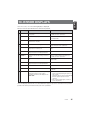
10. ERROR DISPLAYS
If an error occurs, one of the following displays is displayed.
Take the measures described below to eliminate the problem.
General
DVD changer
CD changer
CD
Error Display
Cause
Measure
ERROR 2
A CD is caught inside the CD deck and is
not ejected.
This is a failure of CD deck’s mechanism and
consult your store of purchase.
ERROR 3
A CD cannot be played due to scratches,
etc.
Replace with a non-scratched,
non-warped-disc.
ERROR 6
A CD is loaded upside-down inside the CD
deck and does not play.
Eject the disc then reload it properly.
ERROR 2
A CD inside the CD changer is not loaded.
This is a failure of CD changer’s mechanism
and consult your store of purchase.
ERROR 3
A CD inside the CD changer cannot be
played due to scratches, etc.
Replace with a non-scratched, non-warped
disc.
ERROR 6
A CD inside the CD changer cannot be
played because it is loaded upside-down.
Eject the disc then reload it properly.
ERROR 2
A DISC inside the DVD changer cannot be
played.
This is a failure of DVD mechanism and
consult your store of purchase.
ERROR 3
A DISC cannot be played due to scratches,
etc.
Retry or replace with a non-scratched, nonwarped-disc.
ERROR 6
A DISC inside the DVD changer cannot be
played because it is loaded upside-down.
Eject the disc then reload it properly
ERROR P
Parental level error
Set the correct Parental level.
ERROR R
Region code error
Eject the disc and replace correct region
code disc.
AMP GRD
The speaker protection circuit is operating.
During this operation, if any volume
operation is performed, the display shows
“AMP GRD”.
1. Turn down sound volume. Function can
also be restored by turning the power off
and on again.
(Speaker volume is reduced automatically
when the speaker protection circuit
operates).
2. If the sound is muted again, consult our
service department.
If an error display other than the ones described above appears, press the reset button. If the problem
persists, turn off the power and consult your store of purchase.
DXZ445
25
English
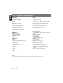
11. SPECIFICATIONS
FM Tuner
Audio
Frequency Range:
87.9 MHz to 107.9 MHz
Usable Sensitivity:
9 dBf
50dB Quieting Sensitivity:
15 dBf
Alternate Channel Selectivity:
70 dB
Stereo Separation (1 kHz):
35 dB
Frequency Response (±3 dB):
30 Hz to 15 kHz
Maximum Power Output:
208 W (52 W ✕ 4 ch)
Continuous Average Power Output:
17 W ✕ 4, into 4 1, 20 Hz to 20 kHz, 1%THD
Bass Control Action (60 Hz/100 Hz/200 Hz):
±15 dB
Treble Control Action (10 kHz/15 kHz):
±12 dB
Line Output Level (CD 1 kHz):
2V
AM Tuner
Frequency Range:
530 kHz to 1710 kHz
Usable Sensitivity:
25 µV
CD Player
System:
Compact disc digital audio system
Usable Discs:
Compact disc
Frequency Response (±1 dB):
10 Hz to 20 kHz
Signal to Noise Ratio (1 kHz):
100 dB
Dynamic Range (1 kHz):
95 dB
Harmonic Distortion:
0.01%
General
Power Supply Voltage:
14.4 V DC (10.8 to 15.6 V allowable), negative
ground
Current Consumption:
Less than 15 A
Speaker Impedance:
4 1 (4 1 to 8 1 allowable)
Weight / Source unit:
2.64 lb. (1.2 kg)
Weight / Remote control unit:
1 oz. (30 g) (including battery)
Dimensions / Source unit:
7" (Width) ✕ 2" (Height) ✕ 6-1/8" (Depth)
[178 (W) ✕ 50 (H) ✕ 155 (D) mm]
Dimensions / Remote control unit:
1-3/4" (Width) ✕ 4-5/16" (Height) ✕ 1-1/8"
(Depth)
[44 (W) ✕ 110 (H) ✕ 27 (D) mm]
Note:
• Specifications and design are subject to change without notice for further improvement.
26
DXZ445
Clarion Co., Ltd.
All Rights Reserved. Copyright © 2003: Clarion Co., Ltd.
Printed in China / lmprime en Chine / Impreso en China
2003/12
PE-2626B
280-8008-00
Printed in China 1 imprime en Chine Ilmpreso en China
284·9882·00
2003/11
......;...-----------......:;.;;,;;.;;.;.~-----=:::..:..=::..::.:=---------------------------------,
clarion
InstaliationlWire Connection Guide
Manuel d'installation et de connexion
Guia de instalaci6n/conexion de cables
GIrD . . . . . . .
-1.
BEFORE STARTING I PREPARATIFS I ANTES DE COMENZAR
1. This set is exclusively for use in cars with a
negative ground, 12 V power supply.
2. Read these instructions carefully.
3. Be sure to disconnect the battery "8" terminal
before starting. This is to prevent short circuits
during installation. (Figure 1)
a
1. Cet appareil est exclusivement destine etre
utilise dans les voitures avec une alimentation
12 V masse negative.
a
1. Esta unidad ha sido disenada para utilizarse
exclusivamente en automoviles con fuente de
alimentacion de 12 V, Y negativo amasa.
2. lire ces instructions attentivemen!.
2. Lea cuidadosamente estas instrucciones.
3. S'assurer de debrancher la borne "8" de la
3. Antes de comenzar, cerciorese de desconec-
batterie avant de commencer. Cela evitera les
court-circuits pendant !'installation. (Figure 1)
Car battery
Batterie de voiture
Bateria del autom6vil
tar el terminal "8" de la bateria. Esto es para
evitar cortocircuitos durante la instalacion.
(Figura 1)
..........
-2.
Figure 1 / Figure 1 / Figura 1
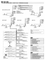
CAUTIONS ON INSTALLATION' PRECAUTIONS AU SUJET DE L'INSTALlATION , PRECAUCIONES PARA LA INSTALACION
1. Prepare all articles necessary for installing the source unit before
starting.
1. Avant de commencer, prE3parer toutes les pieces necessaires pour
installer I'appareil pilote.
1. Antes de comenzar, prepare todos los elementos necesarios para
instalar la unidad fuente.
2. Install the unit within 30 0 of the horizontal plane. (Figure 2)
2. Installer I'appareil avec un angle inferieur a 30° par rapport it !'horizontal. (Figure 2)
2. Instale la unidad con un angulo de 30 0 sobre el plano horizontal.
(Figura 2)
3. S'i1 est necessaire d'effectuer certains travaux sur la carrosserie
3. Si tiene que realizar cualquier trabajo en la carroceria, como
3. If you have to do any work on the car body, such as drilling holes,
consult your car dealer beforehand.
4. Use the enclosed screws for installation. Using other screws can
cause damage. (Figure 3)
comme percer des trous, consulter d'abord votre concessionnaire
automobile.
taladrado de orificios, etc., consulte al proveedor de su automovil.
4. Use los tornillos incluidos para la instalacion. EI uso de otros
tornillos puede causar danos. (Figura 3)
4. Utiliser les vis fournies pour I'installation. L:utilisation d'autres vis
peut causer des dommages. (Figure 3)
I
Chassis 1 Chassis 1 Chasis
1
Chassis Chassis Chasis
~_-_-_- ""'''''Oommo"""",,
Max. 30'/30' max. I Max. 30
i;-m-I-e-m-m-m-ax-.-IM"-ax. 8 mm
..........
-3.
Figure 3/ Figure 3/ Figura 3
Figure 2/ Figure 2/ Figura 2
INSTALLING THE SOURCE UNIT 'INSTALLATION DE L:APPAREIL PILOTE 'INSTALACION DE LA UNlOAD FUENTE
• Universal Mount
• Montage universel
• Montaje universal
1. Place the universal mounting bracket into the instrument panel, use a
screwdriver to bend each stopper of the universal mounting bracket
inward, t-hen secure the stopper as shown in Figure 4.
1. Placer Ie support de montage ,;niversel dans Ie tableau de bard,
utiliser un tournevis pour replier vers I'exterieur chaque languette du
support de montage universel. puis fixer les languettes comme
montre sur la Figure 4.
1. Coloque el soporte de montaje universal en el tablero de instrumentos, utilice un destornillador para doblar cada reten del soporte de
montaje universal hacia adentro, y despues asegure el reten como se
muestra en la Figura 4.
2. Wire as shown in Section 6.
3. Insert the source unit into the universal mounting bracket until it locks.
4. Take care of the top and bottom of the outer escutcheon and mount it
so that all the hooks are locked.
2. Cabler comme montre dans la Section 6.
2. Conecte los cables como se muestra en la Seccion 6.
3. Inserer I'appareil pilote dans Ie support de montage universel jusqu'a
3. Inserte la unidad fuente en el soporte de montaje universal hasta que
quede enganchado.
ce qu'iI soit bloque.
4. Reperer Ie haut et Ie bas de I'ecusson exterieur et Ie monter de
maniere que tous les crochets soient verrouilles.
Notes:
1) Some car models require special mounting kits for proper
installation. Consult your Clarion dealer for details.
2) Fasten the front stopper securely to prevent the source unit from
coming loose.
4. Tenga cuidado con la partes superior e inferior de la pieza ornamental exterior, y montela de forma que todos los ganchos queden
bloqueados.
Remarques:
1) Certains modeles de voiture necessitent un kit de montage special
pour une installation correcte. Consulter Ie revendeur Clarion pour
les details.
Notas:
2) Serrer fermement la languette avant pour eviter que I'appareil
pilote ne se desserre,
2) Apriete con seguridad el retan frontal para evitar que se afloje la
unidad fuente.
• Console openIng dimensions
• Dimensions d'ouverlure de la console
• Dlmensiones de la abertura de la consola
Hole
Trou
Orificio
r
1) Algunos modelos de autom6viles requieren juegos de montaje
especiales para realizar la instalaci6n apropiada. Solicite los
detalles a su proveedor Clarion.
lnstrument panel
Tableau de bord
Tablero de instrumentos
e
. - - - - Stoppers
Languetles
Retenes
ee
ee
//~
Hexagonal bolt
Ecrou hexagonal
Perno hexagonal
Strap
Armature
Banda
* This part is not provided in some models.
* Cette piece n'existe pas sur tous les modeles,
Esta pieza no se suministra con algunos modelos.
Top
Haut
Parte superior
*
t
Universal mounting bracket
Support de montage universel
Soporte de montaje universal
Installation direction
/'L..,
Sens d'installation
~
Direcci6n de instalaci6n
Spring
Ressort
Resorte
Stoppers
languetles
Retenes
+
Bottom
Bas
Parte inferior
Outer escutcheon side view
Vue lateraIe de l'ecusson exterleur
Vista lateral de la pleza ornamental exterior
Outer escutcheon
Ecusson exterieur
Pieza ornamental exterior
Figure 4/ Figure 4/ Figura 4
Note:
Before attaching the universal mounting bracket, slightly bend
the spring toward the inside with your fingers and attach it to the
side of car.
Remarque:
Avant de fixer Ie patin de montage universel, pliez iegerement Ie
ressort vers I'interieur avec les doigts et fixez-Ie sur Ie cote de la
voiture,
Nota:
Antes de fijar el soporte de montaje universal, doble
Iigeramente el resorte hacia el interior con los dedos y ffjelo en
la parte lateral del autom6vil.
• PRECAUCION
• PRECAUTION
Remove the stopper following the procedures below when this source unit is installed
without the universal mounting bracket.
• 'Precaution
Retire el tapon despues de los siguientes procedimientos indicados abajo cuando esta
unidad de la fuente esta instalada sin el soporte de montaje universal.
Retirer la languette en procedant comme suit pour installer Ie module source sans la
patte de montage universel.
1. Remove the screw from the source unit (Figure 5).
1, Quite el tornillo de la unidad de la fuente (Figura 5).
1. Retier la vis du module source (Figure 5).
2. Remove the stopper from the source unit (Figure 6).
2, Quite el tapon de la unidad de la fuente (Figura 6).
2, Retirer la languette du module source (Figure 6).
3. Install the remove screw to the source unit (Figure 7).
3, Instale el tornillo retirado de la unidad de la fuente (Figura 7),
3. Fixer la vis ainsi retiree sur Ie module source (Figure 7).
• Securely attach the screw.
• Apriete firmemente el tornillo,
Note:
Store the removed stopper in a safe place together with the Instruction Manual.
* Fixer la vis a fond.
Remarque:
Ranger la languette retiree en lieu sOr avec Ie mode d'emploi.
Nota:
Guarde el tapon retirado en un lugar seguro junto con el Manual de Instrucciones.
Example 1/Exemple 1/Ejemplo 1
Example 21Exemple 21Ejemplo 2
• PRECAUTION
Push in the protruding part as shown in the figure.
IIIIPRECAUCION
Em\?uje la parte saliente como se muestra en la figura,
• PRECAUTION
Appuyez sur la piece faisant saillie comme indique sur la figure,
(j) Stopper/LanguetteITap6n
® Source UnitIModule source/Unidad de la fuente
® ScrewdriverlToumevis/Destornillador
@ ScrewNislTornillo
(j) Stopper/LanguetteITap6n
® Source UnitlModuie sourcelUnidad de la fuente
..
Figure 51 Figure 5 I Figura 5
Figure 61 Figure 61 Figura 6
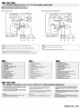
• Fixed Mount (Using the bracket originally equipped in vehicle)
This unit is designed for fixed installation in the dashboard.
If the vehicle is equipped with a factory-installed radio, install the source unit with the
parts and screws marked (*). (Figure 11)
If the vehicle is not equipped with a factory-installed radio, obtain an installation kit to
install the source unit in the following procedure.
1. Secure the mounting brackets to the chassis as shown in Figure 11. When the
source unit is installed without the universal mounting bracket, holes exist;
modification, such as drilling new holes, of the mounting brackets may be required
for other models.
..
Figure 81 Figure 8 I Figura 8
Figure 7 I Figure 7 I Figura 7
Figure 91 Figure 9 I Figura 9
III Montage fixe (Avec la patte fixee a I'origine dans Ie vehicule)
L:apparell est con9u pour une installation fixe dans Ie tableau de bordo
Si Ie vehicule est equipe d'une radio installee en usine, installer Ie module source avec
les pieces et les vis marquees d'un asterisque (*), (Figure 11),
Si Ie vehicule n'est pas equipe d'une radio installee en usiine, se procurer Ie kit
d'installation pour installer Ie module source en procedant comme suit.
1, Fixer les pattes de montage sur la carrosserie comme indique a la Figure 11. Pour
installer Ie module source sans patte de montage universel, les orifices existent
deja; pOllr les autres modeles, iI faudra peuHltre modifier les pattes de montage
(par exemple percer de nouveaux orifices),
2. Wire as shown in Installation (Section 6).
2, Effeciuer les cablages comme indique dans Installation (Section 6),
3. Secure the unit in the dashboard, and then reassemble the dashboard and the
center panel.
3. Fixer I'appareil dans Ie tableau de bord, puis remonter Ie tableau de bord et Ie
panneau central.
Mounting bracket • - - - - - - - - - - - ,
(1 pair for the left and right sides)
Support de montage *
(1 paire, pour les faces gauche et dro/te)
Soporte de montaje •
(1 par para los lados Izquierdo y derecho)
Figure 10 I Figure 10 I Figura 10
• Montura fija (Usando el soporte originalmente equipado en el vehiculo)
Esta unidad ha sido disenado para la Instalacion fija en el tablero de instrumentos.
Si el vehiculo esta equipado con una radio instalada en fabrica, instale la unidad de la
fuente con las piezas los tornillos marcados con (*). (Figura 11)
Si el vehiculo no esta equipado con una radio instalada en fabrica, obtenga un juego de
instalacion para Instalar la unidad de la fuente mediante el procedimiento que se da a
continuaci6n:
1, Asegure los soportes de montaje al chasis como se muestra en la Figura 11.
Cuando la unidad de la fuente esta instalada sin el soporte de montaje universal,
existendo agujeros, puede requerirse una modificacion para otros modelos, tal
como pertoraci6n de nuevos agujeros.
2. Realice el cableado tal como se muestra en instalaci6n (Secci6n 6).
3. Asegure la unidad en el tablero de instrumentos, y luego vueIva armar el tablero
de instrumentos y el panel central.
Dashboard
Tableau de bord
Tablero de Instrumentos
Center Panel (Note 1)
Panneau central (Flemarqure 1)
Panel central (Nota 1)
Figure 11 / Figure 11 / Figura 11
• : The parts and SCREW with this mark are used to install radio or included in the
installation kit.
The screws with this mark are originally attached to the vehicle.
Note 1: In some cases, the center panel may require some modification (trimming, filling,
etc.).
Note 2: If a hook on the Installation bracket interferes with the unit, bend and flatten it
with a nipper or a similar tool.
*:
---4.
Flemarque 1: Dans certains cas. if sera parfois necessalre de modii/er Ie panneau central
(decoupe, rempl/ssage, etc,),
Flemarque 2: SI Ie crochet de la patte d'installation Intertere avec I'appareif, Ie pl/er et
rapatir a raide d'une plnce par exemple,
• : Las piezas y los tornillos con esta marca se utilizan para instalar una radio 0 estan
incluidos en el juego de instalaci6n,
Los tornillos con esta marca estan originalmente sujetos al vehrculo.
Nota 1: En algunos casas, el panel central puede requerr cierta modlflcacl6n (Recorte,
relleno, etc.).
Nota 2: SI un gancho en et soporte de Instalacl6n interflere can la unidad, d6belo y
aplastelo can una plnzas de corte u otra herramlenta especial.
*:
REMOVAL OFTHE SOURCE UNIT I DEPOSE DE L'APPAREIL PILOTE I DESMONTAJE DE LA UNlOAD FUENTE
1. When removing the source unit, disassemble it in the reverse of the order in
Section "3. INSTALLING THE SOURCE UNIT'.
2. Remove the Detachable Control Panel (DCP).
* For instructions on removing the DCP, refer to the owner's manual.
3. Press the outer escutcheon upward and remove it. (Figure 12)
4. Insert and lock the hook plates. (Figure 13)
5. Pull the hook plates to remove the source unit.
---5.
: Les pieces et la VIS portant cette marque servent pour I'installation de la radio ou
sont fournies avec Ie kit d'installation.
* : Les vis portant cette marques sont montees d'origine dans Ie vehicule.
1, Lors de la depose de I'appareil pilote, demonter dans I'ordre inverse de la Section
"3. INSTALLATION DE l:APPAREIL PILOTE",
2, Deposer Ie clavier de commande amovible (DCP),
" Pour les instructions sur Ie retrait du clavier de commande amovible (DCP), se
reterer au mode d'emploi.
3. Presser I'ecusson exterieur vers Ie haul et Ie retirer. (Figure 12)
4, Inserer et verrouiller les plaques a crochet (Figure 13)
5. Tirer sur les plaques a crochet pour retirer I'appareil pilote,
1. Para desmontar la unidad fuente, realice el procedimiento inverso al de la Seccion
"3. INSTALACI6N DE LA UNIDAD FUENTE".
2. Desmonte el panel de control desmontable (DCP).
• Para instrucciones sobre c6mo desmontar el DCP, consulte el manual de
instrucciones.
3. Presione la pieza ornamental ex1erior hacla afuera y extraigala. (Figura 12)
4. Inserte y bloquee las placas de enganche. (Figura 13)
5. Tire de las placas de enganche para extraer la unidad fuente.
Figure 13/ Figure 13/ Figura 13
Figure 12/ Figure 121 Figura 12
CAUTIONS ON WIRING I PRECAUTIONS AU SUJET DES CONNEXIONS I PRECAUCIONES PARA LA CONEXION DE CABLES
• 1. Be sure to turn the power off when wiring.
2. Be particularly careful where you route the wires.
Keep them well away from
the engine, exhaust pipe, etc. Heat may damage the wires.
3. If the fuse should blow, check that the wiring is correct.
If it is, replace the fuse with a new one with the same amperage rating as the
original one. (Figure 14)
Note:
There are various types of fuse holder. Do not let the battery side touch other
metal parts.
4. Connect the CeNET extension cable fully and securely until it locks. When the
CeNET extension cable is pulled, hold the slide cap part and pull it towards you.
• When the CeN ET extension cable is ex1ended or branches, use extension
cable CCA-520 (2.5m) or CCA-521 (0.6m), orY-adapter CCA-519 (each of
them is sold separately),
• Use the CeNET extension cable made by Clarion.
5, When the main power supply fuse in the car is 15 A or less, purchase an
automotive cable that can withstand 15 A and supply this unit with power
directly from the battery to ensure that the unit will operate normally.
Note that a fuse must be installed at a distance no longer than 30 cm from the
cable battery terminal to prevent accidents.
III 1, S'assurer de mettre I'appareil hors circuit avant de faire Ie cablage.
2, Faire particulierement attention lors de I'acheminement des fils,
Les eloignel' du moteur, des tuyaux d'echappement, etc, La chaleur risque
d'endommager ces fils.
3. Si Ie fusible saute, verifier si Ie cablage est correct
Si Ie fusible est grille, Ie remplacer par un fusible neuf de meme amperage que
Ie fusible d'origine, (Figure 14)
2. Sea especialmente cuidadoso al dirigir y fijar los cables. mantengalos alejados
del motor, tubo de escape, etc. EI calor puede danar los cables.
3. SI el fusible se quema, revise las conexiones.
Si esta quemado, reemplace el fusible por otro nuevo con el mismo valor de
amperaje que el original. (Figura 14)
Nota:
Remarque:
II y a different type de porte-fusible, La borne du cote batterle ne dolt pas
toucller d'autres pj(,ces metalliques,
4, Connecter Ie cable d'extension CeNET completement et solidement jusqu'a ce
qU'il soit verrouille, Pour tirer Ie ciible d'extension CeNET, tenir la partie
coulissante du capuchon et tirer vers vous,As
* Pour etendre au deriver Ie cable d'extension CeNET, utiliser Ie cable
d'extension CCA·520 (2,5 m [8 piedsJ) ou CCA-521 (0,8m [2 pieds]), ou
l'adaptateurY CCA·519 (ces cables sont vendus separement)
* Utiliser les cables d'extension CeNET fabriques par Clarion,
5, Si Ie fusible d'alimentation principale de la voiture est de 15 A ou moins,
achetez un cable automobile qui peut supporter 15 A et alimenter cet apparell
directement a partir de la batterie et assurer que I'appareil fonctionnera
nonnalement.
Notez qu'un fusible doit etre installe a une distance de mains 30 cm de borne
de la batterie pour eviler tout accident
Fuse case
Boitier a fusible
Caja de fusible
III 1. Antes de hacer las conexiones, asegurese de desconectar la alimentacion de la
unidad.
~
Fuse
Fusible
Fusible
r
.,
Figure 141 Figure 141 Figura 14
Exlsten varlos tipos de portafuslbles. No permlta que el terminal dellado de la
baterfa toque otras partes metal/cas.
4. Conecte el cable prolongador CeNET completa y seguramente hasta que
chasquee. Para desconectar el cable, sujete la parte de la tapa deslizable y tire
hacia usted.
• Para prolongar 0 ramificar el cable prolongador CeNET, utilice un cable
prolongador CCA-520 (2,5 m) 0 CCA-521 (0,6 m), 0 un adaptador en Y CCA519 (vendidos aparte).
• Utilice un cable prolongador CeNET fabricado por Clarion.
5. Cuando el fusible de alimentacion principal del automovil sea de 15 A 0 menos,
adquiera un cable para autom6vll que pueda resistir 15 A Yalimente esta
unidad directamente desde la baterfa para cerciorarse de que pueda funcionar
normalmente.
Tenga en cuenta que para evitar accidentes, debera instalar un fusible en al
cable que va a terminales de la baterfa a una distancia no superior a 30 cm.
GIID _ _ . . .
-6.
WIRE CONNECTIONS I CONNECTIQUE I CONEXION DE CABLES
...
••
...
...•
®
®
.DXZ945MP/DXZ745MP
___~~1
I
Antenna
Antenne
Antena
~
~~®
,
®
®
®
@
To external amplifier
To eliminate audio short circuits, do not remove the caps of unused RCA cables.
CAUTION: Please make sure when connecting external power amplifier, that you properly, to the car
chassis, ground the amplifier. If this is not done, severe damage to the source unit may
happen.
Vers un amplificateur externe
" Pour supprimer les courts-circuits audio, ne pas retlrer les capuchons des cables RCA non utilises.
ATTENTION: Lorsque vous raccordez un ampli de puissance externe, laltes bien attention Ii meltre
correctement I'amplificateur Ii la masse sur Ie chassis de la voiture. Sinon. vous
risquez d'endommager gravement I'appareil pilote.
A un ampllficador externo
Para ehminar los cortocircuitos de audio. no quite los casquillos protectores de los cables RCA no utilizados.
PRECAUCI6N: Cuando conecte un amplificador de potencla externo, cerciorese de ponerlo
adecuadamente a mase en el chasls de su automovil.SI no 10 hiclese, la unldad
fuente podrla daiiarse seriamente.
*
*
.DXZ845MC
To external unit
Vers un appareil externe
A un unidad externo
To wireless head phone UNIT
Vers Ie casque sans til
A la unidad de auriculares inalambricos
~
II 1::::::1
L..-------C-e-N-ETtput
f
Entree CeNET
Entrada de CeNET
®
:....
• DXZ645MP
•
...
...•
®
®
@
®
.DXZ545MP
...•
@
•
®
®
...
...
@
~
@
Antenna
Antenne
Antena
I
nooJP---+j®
CeNET input
Entree CeNET
Entrada de CeNET
G)
®
®
®
~oCIIII!illj~®
.DXZ445
®
@
... ®
• ®
... ®
@
@
~
'---f
CeNET input
Entree CeNET
Entrada de CeNET
16-Pin Connector Extension Lead
(attached to the source unit)
Fil prolongateur-connecteu' 16 broches
(attache sur i'apparsil pliote)
Cable prolongador de 16 contactos
(fijado a la unidad luente)
I "I
'--'lIIIIl...
!!tI@
f
•
I
@ ...
nDa=» ~®
....
Antenna
Antenne
Antena
,-oIIIICE!!!IIlJ@
Antenna
Antenna
Antena
1:::::1
CeNET input
Entree CeNET
Entrada de CeNET
® •
Note:
Some units do not have connecting leads or jacks.
(Refer to *.)
Remarque:
Certains appareils n'on! pas de condllcteurs de connexion Oll de prises.
(Voir 1<.)
EEl Gray I C£,Gris I EElGris
Front Right
Avant droit
Delantero derecho
Brown wire (Phone mute lead)*
Fil marron (1i1 de sourdine de telepl1one)*
Conductor marr6n (Conductor de sllenclamiento de teh~1ono)*
8Gray/BIack I ,'C)Gris/noir I 8Grls/negro
EEl White I
(f) BianG
Nota:
Algunas unidades no tienen cables de conexi6n ni conectores.
(Refierase a *.)
I EEl Blanco
Front Left
Avant gauche
Delantero Izquierdo
Connect to cellular phone mute lead.
Brancher au fii de sourdine du telephone mobile.
Conectelo al conductor de silenciamiento del telelono modular.
8 White/Black I () Blanc/noir I 8 Blanco/negro
Yellow wire (Memory back-up lead)
Fil jaune (Iii de soutien memoire)
Conductor amarillo (Conductor de proteccion de la memoria)
Connect directly to battery.
Brancher directement a la baUerie.
Conectelo directamente a la baterla.
Fuse (15A)
Fusible (15A)
Fusible (15 A)
EElPurple I (t)Pourpre / EEl Purpura
Rear Right
Arrlere droit
Trasero derecho
8Purpie/BIack / 8 Pourpre/noir / 8 Purpura/negro
No.
(IJ
EEl Green / (i)Vert / (i)Verde
Rear Left
Arrlere gauche
Trasero izqulerdo
Yellow wire (Bus power lead)*
Fil jaune (fil de bus d'allmentation)*
Conductor amarillo (conductor de alimentaci6n de bus)*
8Green/Black/ OVert/noir / 8Verde/negro
Connect directly to battery.
Brancher dir9ctement
4·Speaker system
Systeme a 4 haut-parleurs
Sistema con 4 altavoces
Fuse (3A)
Fusible (3A)
Fusible (3A)
•+
a la batterie.
Conectelo directamente a la baterla.
o
@
@
®
(j)
@
®
Red wire (Power lead)
Fil rouge (Iii d'alimentation)
Conductor rojo (Conductor de alimentacion)
AccessoryEEl12 V
Accessoire (tl 12 V
AccesorioEEl12 V
or
®
®
@l
@
@
Description
FRONT RIGHT Gray (Red)
FRONT LEFT Gray (White)
REAR RIGHT Black (Red)
REAR LEFT Black (White)
REAR RIGHT/(SUB WOOFER RIGHT) Black (Red)
REAR LEFT/(SUB WOOFER LEFT) Black (White»
SUB WOOFER RIGHT Violet (Red)
SUB WOOFER LEFT Violet (White)
AUX INPUT RIGHT Red (Red)
AUX INPUT LEFT Red (White)
2-Z0NE OUTPUT RIGHTGreen (Red)
2-Z0NE OUTPUT LEFTGreen (White)
BluelWhite wire (Amplifier turn-on lead)
Fil bieu/blfJl1C (n; de mise sous tension telecommandable de i'amplilicateur)
Conductor azul/blanco (Conductor de conexion de la alfmentacion del ampliflcador)
2·Speaker system
Systeme 2 haut-parleurs
Sistema con 2 altavoces
a
Right
Droit
Derecho
r---- EEl Gray / (i)Gris I EElGris
II
~
Left
Gauche
Izquierdo
:(
8Gray/Black I (';)Grisinoir I 8Grislnegro
r---- EEl White / CD Blanc / EEl Blanco
II
.......... 8White/Black /
!:\
Cl Blandnoir I 8Blanco/negro
(
EElPurple / CfJPourpre I EEl Purpura
X
,)
8 Purple/Black / (ee) Pourpre/nair / 8Purpura/negro
Not used.
Insulate each wire.
8Green/BIack / ()Vert/noir / 8 Verde/negro
inutilise.
Isoler chaque m.
, No se utlllza.
AIsle tOd~~ los conductor~s~
_
i
)
EElGreen / (DVerl / EElVerde
--~
,
(
Connect to remote turn-on lead 01 amplilier.
Brancher au Iii de mise saus tension telecommandabie
de I'amplificateur.
Conectelo al conductor de conexion automatlca de la
alimentacion del amplificador.
Black wire (Ground lead)
Fil noir (fil de terre)
Conductor negro (Conductor de puesta amasa)
Connect to vehicle chassis ground.
Brancher a Ie terre du chassis du vehlcule.
Conectelo a una parte metalfca del chasis del vehfculo.
OrangelWhile wire (Illumination lead)
Fil omn(Jeiblanc (iii d'eclairage)
Conductor anaranjado/blanco (conductor de i1uminacion)
No.
Connect it to the car power supply terminal for illumination.
La connecter a la borne d'alimentation de I'eclairage
de ia vaiture.
Conectelo al terminal de alimenlacion del automovil para
iluminaci6n.
Blue wire (Auto antenna lead)
Fil blau (fil de I'antenna elactrique)
Conductor azul (conductor para la antena motorizada)
Connect It to the car power supply terminal lor the antenna.
La connecter
a Ie borne d'alimentation de l'antenne electrlque
de Ja voiture,
Conectelo al terminal de alimentacion de la antena.
(IJ
®
®
@
@
®
(j)
®
®
@l
@
@
Descripcion
DELANTERO DERECHO Gris (Rojo)
DELANTERO IZQUIERDA Gris (Blanco)
TRASERO DERECHO Negro (Rojo)
TRASERO IZQUIERDA Negro (Blanco)
TRASERO DERECHO/(ALTAVOZ DE SUBGRAVES DERECHO) Negro (Rojo)
TRASERO IZQUIERDAI(ALTAVOZ DE SUBGRAVES IZQUIERDA) Nearo (Blanco)
ALTAVOZ DE SUBGRAVES DERECHO Violado (Rojo)
ALTAVOZ DE SUBGRAVES IZQUIERDA Violado (Blanco)
Entrada auxiliar (AUX INPUT) del canal derecho (Rojo)
Entrada auxiliar (AUX INPUT) del canal IZQuierdo (Blanco)
SALIDA DE ZONA 2 DERECHO VERDE (Roio)
SALIDA DE ZONA 2 IZQUIERDO VERDE (Blanco)
---7.
SYSTEM EXAMPLElEXEMPLE DE SYSTEME/EJEMPLO DESISTEMA
• Example of the system using an external amplifier (Audio Visual)
• Exemple de systeme utilisant un amplificateur exterieur. (audio·visuel)
• Ejemplo de sistema utilizando un amplificador externo (audiovisual)
• DXZ845MC/DXZ645MP/DXZ545MP/DXZ445
• DXZ945MP/DXZ745MP
~6:=:: ~
r--1;lr;;=:1:;::::::::q1;l'-----12
o
L.:.J L.:.J
-_.
'.,
~
CD
... _-'
____® _10
;~_
"
,
Amp', Amp'
"
,
""
'
"
,,'
"
""
,'
®
--1--' ._-~--'
0:
*:-
_
-------'
.. ",
;~
,
~" ... ..,
"1'
"
,
Amp', Amp'
""
,'
"
'
""
,'
""
,'
~
Note:
Use a CeNET extension cable that is less than 20 m in length. (including the Y-adapter CCA-519.)
Remarque:
Utiliser un c{jble d'extension CeNET infer/eur
r---------
~
:::l=O--..---o<:0
~L.!.J
Note:
a 20 m de long (en complant aussi I'adaptateur Y CCA-519),
Nota:
Utilice un cable prolongador CeNET de menos de 20 m de longitud (incluyendo el adaptador en Y CCA-519).
DXZ445 does not have a "2-Z0NE OUTPUT'terminal. (Refer to *.)
Remarque:
Le DXZ445 /1e possede pas de borne "2-Z0NE OUTPUT'. (Voir *.)
Nota:
EI modelo DXZ445 no posee terminal "2-Z0NE OUTPUT'. (Refierase a *.)
* This source unit can control a total of 2 changers except 2 DVD changers exist in the system.
" Cappareil pilote est capabie de commander 2 changeurs au total en plus des 2 changeurs de DVD qui existent dans Ie
systeme.
* Esta unidad fuente puede controlar en total 2 cambiadores excepto los 2 cambiadores de discos DVD del sistema.
G)
®
®
@
®
®
<V
®
®
@)
®
@
@
@
@
@
@
@
<w
Source unit
GeNET extension cable
Y·adaoter (sold separately)
GDchanaer
DVD chancer
RCA extension cable (sold seoaratelv)
4-Channel oower amolifier
Front speakers
Rear speakers
Monitor
SIRIUS satellite radio receiver
TV tuner module
ch surround decoder
ch surround decoder control unit
Ootical connector cable
Center speaker (with amplifier)
Subwoofer (with amplifier)
External unit
Wireless head phone unit
5.1
5.1
~1?-
Appareil pilote
.... __._---_._._--_... _-_._---"Cable d'extension GeNET
(;j) Adaotateur Y (vendu seoarement)
@ Chanoeur de CD
i2.b.~.!:l~! de DV[)_ ____,_ _ _ _ _ _,_______..
@ Cable de rallonQe RCA (vendu seoarement)
<V Ampliflcateur de puissance 4 canaux
@ Haut-parleurs avant
@) t1..§..t,lt-par!Q.l}.I2.i!!I!~~.,_,_,, ____,______,,_____...._._.._ _ _ _ _
@' Moniteur
@ Becep..teur '.:.<1919 sat~lli~~i3~_ ..___.__ ,,__._..__.____,______
@ Module tuner TV
Decodeur surround 5. i canaux
.
..
.~ ----------_._-------_.
@ Module de cornmande de decodeur surround
canaux
@ Cabie de connexion ootique
@ Haut-parleur central (avec amplificateur)
~)
..@....
__ __
5.1
@
®
®
@
®
@
<V
®
®
@)
®
@
@
._._--~_._--_
_~
@ ~-oof~{?~£~~plifiC?.!eurL----,
.\f~-
G)
n __
Appareil externe
Casque sans fii
@
@
@
@
@
@)
Unidad fuente
Cable prolongador CeNET
Adaotador en Y (vendido aoarte)
Cambiador de discos comoactos
Cambiador de DVD
Cable de extension RCA
Amplificador de potencia de 4 canales
Altavoces delanteros
Altavoces traseros
Monitor
Sintonizador SIRIUS de recepcion radio via satalite
Modulo sintonizador de television
Descodificador de
ch surround
Unidad de control de Descodificador de
ch surround
Cable conector ootico
Altavoz central (con amplificador)
Altavoz de subQraves (con amplificador)
Unidad externo
Unidad de auriculares inalambricos
5.1
--
5.1
---8.
GENERAL CAUTIONS I PRECAUTIONS GENERALES I PRECAUCIONES GENERALES
1. Do not open the case. There are no user serviceable parts inside. If
you drop any1hing into the unit during installation, consult your dealer
or an authorized CLARION service center.
2. Use a soft, dry cloth to clean the case. Never use hard cloth, thinner,
benzen, alcohol, etc. For tough dirt, apply a little cold or warm water
to a soft cloth and wipe off the dirt gentry.
IMPORTANT:
Improper installation may cause damage to your unit or car. If you do
not have the appropriate experience, consult a qualified installer.
Cutting chassis wire leads voids the warranty.
1. Ne pas ouvrir Ie coffret. II n'y a pas de pieces reparables par
I'utilisateur I'interieur de I'appareil. Si un objet est tombe dans
I'appareil pendant !'installation, consulter votre revendeur ou un
service apres-vente agree CLARION.
1. No abra la caja. En el interior no hay piezas que pueda reparar el
usuario. Si dentro de la unidad entra algo durante la instalacion,
consuite a su proveedor 0 a un centro de servicio autorizado por
CLARION.
2. Utiliser un chiffon doux et sec pour nettoyer Ie coffret, ne jamais
utiliser un chiffon rigide, un diluant, du benzene, de I'alcool, etc. Pour
enlever la salete tenace, appliquer un peu d'eau froide ou tiMe sur
un chiffon doux et essuyer doucement la salete.
2. Para Iimpiar la caja, utilice un pano suave y seco. no use nunca un
pano duro, diluidor de pintura, benceno, alcohol, etc. Para la suciedad
resistente, aplique un poco de agua fria 0 caliente a un pano suave y
frote suavemente la parte sucia.
IMPORTANT:
Une installation incorrecte peut endommager I'appareil au Ie vehicule.
Si I'on ne possede pas les connaissances requises, consulter un
installateur qualifie. Couper Ie til du chassis annule la garantie.
IMPORTANTlE:
La instalaci6n inapropiada puede causar dafios en su unidad 0 su
autom6vil. Si usted no posee la experiencia apropiada, consulte a un
instalador cualificado. lEI corte de los conductores de puesta amasa
(carrocerfa) anulara la garantfa.
a
Clarion Co., Ltd.
281-0624-00 2003/8
clarion
CLARION LIMITED WARRANTY
For USA and Canada only
If purchased from an authorized Clarion dealer, this product is warranted against all defects in materials and
workmanship for a period of one (1) year from the date of original purchase. Clarion ProAudio products, except for
speakers, are covered by a two (2) year limited warranty when purchased from and installed by an authorized Clarion
dealer. ALL PURCHASES OF CLARION PRODUCTS FROM NON-AUTHORIZED CLARION DEALERS ARE
SUBJECTTO FURTHER WARRANTY RESTRICTIONS AS DESCRIBED BELOW.
The conditions of this limited warranty and the extent of responsibility of Clarion Corporation of America ("Clarion")
under this limited warranty are as follows:
1. PROOF OF DATE OF PURCHASE WILL BE REQUIRED FOR WARRANTY SERVICE OF THIS PRODUCT.
IN THE CASE OF THE TWO (2) YEAR LIMITED WARRANTY FOR CLARION PROAUDIO PRODUCT, PROOF OF
INSTALLATION BY AN AUTHORIZED CLARION DEALER IS REQUIRED. INFORMATION ABOUT CLARION
AUTHORIZED WARRANTY SERVICE CENTERS MAY BE OBTAINED BY CONTACTING OR WRITING CLARION
ATTHE ADDRESS LISTED BELOW.
2. This limited warranty will become void if service performed by anyone other than an approved Clarion Warranty
Service Center results in damage to the product.
3. This limited warranty does not apply to any product which has been subject to misuse, neglect or accident,
or which has had the serial number altered, defaced or removed, or which has been connected, installed, adjusted
or repaired, other than in accordance with the instructions furnished by Clarion.
4. This limited warranty does not cover car static or other electrical interferences, tape head or laser pick-up cleaning
or adjustments, or labor costs for the removal or reinstallation of the unit for repair.
5. The sole responsibility of Clarion under this limited warranty shall be limited to the repair of the product or
replacement of the product, at the sole discretion of Clarion.
6. Product must be shipped in its original carton or equivalent carton, fully insured, with shipping charges prepaid.
Clarion will not assume any responsibility for any loss or damage incurred in shipping.
7. CLARION PRODUCTS, INCLUDING PROAUDIO PRODUCTS, PURCHASED FROM A SOURCE OTHER THAN
AN AUTHORIZED CLARION DEALER, INCLUDING ANY AND ALL PURCHASES VIA THE INTERNET FROM A
NON INTERNET AUTHORIZED CLARION DEALER, SHALL NOT BE COVERED BY ANY CLARION LIMITED
WARRANTY TO THE EXTENT ALLOWED BY APPLICABLE LAW. IN THE EVENT AND TO THE EXTENT
APPLICABLE LAW PROHIBITS ELIMINATION OF WARRANTIES UNDER THESE CIRCUMSTANCES,
THE APPLICABLE LIMITED WARRANTY PERIOD SHALL BE DEEMEDTO BE FIFTEEN (15) DAYS FROMTHE
DATE OF ORIGINAL PURCHASE.
8. ALL IMPLIED WARRANTIES EXCEPT TO THE EXTENT PROHIBITED BY APPLICABLE LAW SHALL HAVE NO
GREATER DURATION THAN THE WARRANTY PERIOD SET FORTH ABOVE. UNDER NO CIRCUMSTANCES
SHALL CLARION BE LIABLE FOR ANY LOSS OR DAMAGE, DIRECT OR CONSEQUENTIAL, ARISING OUT OF
THE USE OR INABILITY TO USE THE PRODUCT. BECAUSE SOME STATES DO NOT ALLOW LIMITATIONS ON
HOW LONG AN IMPLIED WARRANTY LASTS OR EXCLUSIONS OR LIMITATIONS OF INCIDENTAL OR
CONSEQUENTIAL DAMAGES, THE ABOVE LIMITATIONS OR EXCLUSIONS MAY NOT APPLY TO YOU.
9. THIS LIMITED WARRANTY GIVES YOU SPECIFIC LEGAL RIGHTS, AND YOU MAY ALSO HAVE OTHER
RIGHTS WHICH VARY FROM STATE TO STATE.
10. The laws of the State of California shall govern and control this limited warranty, its interpretation and enforcement.
11. Should you have any difficulties with the performance of this product during the warranty period, please call or
visit our web site for a listing of Authorized Warranty Service Centers in your area. You may also contact the
Clarion Customer Service at the address listed below for any service help you may need with Clarion products.
In USA:
Clarion Corporation of America
Attn:Customer Service Manager
661 W. Redondo Beach Blvd
Gardena, CA.90247-4201
1-800-GO-CLARION
(310)327-9100
www.c1arion.com
In Canada:
Clarion Canada Inc.
Warranty Service Center
2239 Winston Park Drive
Oakville, Ontario L6H 5R1
(905)829-4600
www.clarioncanada.com
100 CHANNELS OF THE
BEST ENTERTAINMENT ON THE ROAD
Clarion
siriusradio.com
SIn.IU-S--~-----
P
1
2
3
4
5
7
8
9
15
17
20
21
22
23
24
25
26
27
29
ClIP
I"~
Top 40 Hits
Adult Contemporary
Alt Pop Mix
Love Songs
The Best of the 50s/60s
The Best of the 70s
The Best of the 80s
The Best of the 90s
50ft Rock
Eclectic Rock
Rock Hits
Modern Rock
Mainstream Rock
Classic Rock I
Classic Rock II
Classic Alternative
Alternative I
Alternative II
Hard Rock
) 2002 Sirius Satellite Radio Inc.
SIRIUS
--
-----~--
30
31
32
35
36
37
'
Country Hits
Today's Country
Country Mix
Classic Country
Alt Country
Bluegrass
f!II!Iir.
40
42
43
44
45
47
48
49
R&B Hits
Today's R&B
Soul Ballads
Classic Soul
R&B Oldies
Rap Hits
Today's Rap
Classic Rap
----
-
SIIHUS
DANCE
50
51
53
56
,
Dance Hits
Mainstream Dance
Electronica
Disco
285-1887 -00
~--
~
't_v
])D1Jl't'l'JlJ
SIRIUS
, SPORTS
60
61
62
63
65
66
67
Classic Jazz
Latin Jazz
Contemporary Jazz
Smooth Jazz
Standards
Swing
Broadway's Best
-- - - - - - - -
SIRIUS
LA-II
Latin Hits
Latin Pop Mix
Rock en Espanol
Mexicana
Tejano
80
82
85
Symphonic
Chamber Works
Classical Voices
Blues
Reggae
Gospel
Christian Hits
World Music
New Age
Kids
Specialty Showcase
')'\, •
r .,
70
71
72
74
77
90
91
93
94
95
96
99
100
fmlN.ll\»
101
102
104
105
107
108
109
111
11 2
114
11 5
CNBC
FOX News Channel
CNN Headline News
Bloomberg
NPR Now
NPR Talk
PRI's Public Radio Channel
World Radio Network
BSC World Service News
C-SPAN Radio
The Weather Channel
Radio Network
116 Sirius Talk
117 Real Sirius
119 ABC News & Talk
120
121
123
124
125
ESPN Radio Network
ESPNews
Sports Byline USA
Speedvision
OLN Adventure Radio
SiRiUs
HISPANIC
140
142
144
146
147
,~_
ll;~",
BBC Mundo
La Red Hispana
Radio Deportivo
Radio Mujer
Radio Amigo
"",,;.,,.,. I
EtlTERTAltlHEtlT
150 Radio Disney
151 Discovery Radio
152 E! Entertainment Radio
154 A&E Satellite Radio
156 Radio Classics
158 SCI FI
159 Sirius Entertainment
160 Sirius Comedy
161 Sirius Arts
164 Personal Achievement
165 Wisdom Radio
167 African American Talk
168 The Scandal Channel
172 Women's Talk
175 Guy Talk
180 Trucker Channel
184 Preview Channel
\/
9}2,-
SIRIUS
Satellite Radio
GET READY FOR 100 CHANNELS OF THE BEST
IN-CAR ENTERTAINMENT.
You've just purchased a Sirius Satellite Radio receiver that's going
to plug you into 60 original music channels, from today's hits to
R&B oldies to classical masterpieces. From authentic country and
real bluegrass to cool jazz, hot latin, reggae and rock. Plus 40
channels of world-class sports, news and entertainment, like ESPN,
Radio Disney, E! Entertainment Radio, CNBC, Fox News and
Discovery Radio.
EXPERIENCE SIRIUS IN TWO SIMPLE STEPS.
If you haven't already activated your Sirius receiver, here's how:
1. Contact us at siriusradio.com or call toll-free
1-888-539-SIRIUS (7474).
2. Have 3 items on hand:
• A valid credit card or branded debit card
• Sirius ID or Electronic Serial Number (check on
the receiver box or your display control window)
• Your vehicle identification number (VIN)
At Sirius, the emphasis is on the music and entertainment you
want. From now on, it's just you, the road and the music.
Activate today to get 100% commercial-free music, plus
a Welcome Kit with a detailed Channel Guide.
ONLY FROM SIRIUS • 100 channels of digital entertainment, coast-to-coast
• 60 original music channels, all commercial-free
• 40 world-class sports, news and entertainment channels
• S>PLEX technology for superior sound resolution
.\
/
~\
SIRIUS
Satellite Radio