1
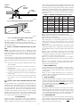
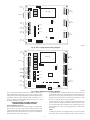
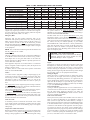
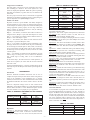
Installation
and Operating Instructions
3-ZONE CONTROL
ZONEBB3Z(AC/HP)01
Cancels:
TABLE OF CONTENTS
NEW
II ZONEKIT.0.13
11-04
This instruction covers the physical installation and start up of the
Bryant 3-Zone system. Use this instruction to guide the actual
installation process after all the air side decisions have been made.
Page
SAFETY CONSIDERATIONS...................................................1
INSTALLATION CONSIDERATIONS....................................1
INTRODUCTION ........................................................................1
INSTALLATION ......................................................................1-4
• Check Equipment And Job Site ..............................................1-2
• Component Location And Wiring Considerations .....................2
• Install Components......................................................................2
• Install Zone Dampers...............................................................2-3
• Install Barometric Bypass Damper..........................................3-4
• Install Leaving Air Temperature (LAT) Sensor.........................4
• Install Heat Pump Temperature (HPT) Sensor ..........................4
SYSTEM WIRING ...................................................................4-5
• Wire Thermostats ........................................................................4
• Wire Equipment...........................................................................4
• Wire Dampers..............................................................................4
• Wire Remainder .......................................................................4-5
UNDERSTANDING SYSTEM OPERATION ......................5-7
SYSTEM SETUP ....................................................................7-10
NOTE: Read the entire instruction manual before starting the
installation.
1. Install in non-condensing areas with ambients between
32°F and 158°F.
2. A TXV is required on the indoor coil when used with all
residential split system equipment.
3. A separate transformer is not needed to power the 3-Zone
system. Up to five dampers may be used in each zone by
electrically connecting them in parallel.
4. Load calculations must be performed for each zone’s peak
demand. Size each zone duct for at least its peak demand
plus 25%. Size equipment for the building block load, not
the sum of zone peak demands. It is important that the
equipment not be oversized.
5. When only two zone operation is needed, any two of the
three zone connections may be used. There is no inherent
priority dependent on zone number.
CAUTION: UNIT DAMAGE HAZARD
Failure to follow this caution may result in unit damage.
TXV on indoor coil is required with all residential split
system equipment.
SAFETY CONSIDERATIONS
Improper installation, adjustment, alteration, service, maintenance,
or use can cause fire, electrical shock, or other conditions which
may cause personal injury or property damage. Consult a qualified
installer, service agency or your distributor or branch for information or assistance. The qualified installer or agency must use
factory-authorized kits or accessories when modifying this product. Refer to the individual instructions packaged with the kits or
accessories when installing.
Follow all safety codes and wear safety glasses. Have fire
extinguisher available. Read these instructions thoroughly and
follow all warnings or cautions attached to the unit. Consult local
and state building codes and Sheet Metal and Air Conditioning
National Association (SMACNA) for special installation requirements.
Recognize safety information. This is the safety-alert symbol .
When you see this symbol on the unit or in instructions and
manuals, be alert to the potential for personal injury.
Understand the signal words DANGER, WARNING, and CAUTION. These words are used with the safety-alert symbol. DANGER identifies the most serious hazards which will result in severe
personal injury or death. WARNING signifies hazards which
could result in personal injury or death. CAUTION is used to
identify unsafe practices which would result in minor personal
injury or product and property damage. NOTE is used to highlight
suggestions which may result in ehanced installation, reliability, or
operation.
INTRODUCTION
The Bryant 3-Zone system allows the air conditioning and heating
equipment to control temperatures in 3 distinct spaces or zones
within a building. Each zone has independent temperature settings
controlled by a conventional thermostat.
There are two distinct controllers:
• ZONEBB3ZAC01 - Single Stage Heat / Single Stage Cool
using conventional single stage thermostats.
• ZONEBB3ZHP01 - Three Stage Heat / Two Stage Cool
compatible for HP and multi-stage application thermostats and
equipment.
Each system controller is comprised of a three-zone controller and
a duct temperature sensor.
NOTE: Thermostats are purchased separately.
The comfort temperature settings can change automatically
through the use of schedules if programmable thermostats are
selected. This allows the Bryant 3-Zone to change the temperature
settings in zones to reflect occupancy or usage. The Bryant 3-Zone
system uses motorized air volume control dampers (also called
zone dampers) to regulate the flow of conditioned air into the
zones.
I.
INSTALLATION CONSIDERATIONS
Before the actual installation of a zoning system can begin,
decisions need to be made to determine the number and location of
zones. This affects duct and damper selections.
A.
INSTALLATION
CHECK EQUIPMENT AND JOB SITE
Inspect Equipment
File claim with shipping company, prior to installation, if shipment
is damaged or incomplete.
—1—
II. COMPONENT LOCATION AND WIRING
CONSIDERATIONS
Plan the routing of wiring early to avoid possible problems later
on.
Remember all wires converge at the Bryant 3-Zone system, so its
location is important.
III. INSTALL COMPONENTS
WARNING: ELECTRICAL SHOCK HAZARD
Failure to follow this warning could result in personal
injury or death.
Turn off power to unit before routing control wiring or
any service operation. Remember, there may be more
than one power supply to unit.
A. Install Bryant 3-Zone System
The Bryant 3-Zone System is designed so that wires can enter it
from behind, above, or below. Plan wire routing before mounting.
1. Open door to access eight mounting screw slots
2. Mount to wall using four screws and wall anchors provided.
3. Level and tighten screws.
B. Install Thermostats
All wiring must comply with national, local, and state codes.
A.
Locating Bryant 3-Zone System
All wiring is run back to the Bryant 3-Zone System. Select a
location near the furnace or fan coil where wiring from each
thermostat, each damper actuator, and the equipment itself can
come together easily.
1. Follow manufacturer’s supplied instructions for installing
thermostats.
CAUTION: EQUIPMENT DAMAGE HAZARD
Failure to follow this caution may result in equipment
damage.
Improper wiring or installation may damage the thermostats. Check to make sure wiring is correct before
proceeding with installation or turning on unit.
The Bryant 3-Zone System is approved for indoor use only and
should never be installed with any of its components exposed to
the elements. It may be installed in any area where the temperature
remains between 32° and 158°F, and there is no condensation. The
cover must be installed to prevent damage from other sources. Do
not locate where it will be accessible to children. It may be
mounted in either vertical or horizontal position. Remember that
wiring access is likely the most important consideration.
IV. INSTALL ZONE DAMPERS
Proper selection and sizing of dampers is important for proper
system operation. Selection and sizing information is not provided
in this installation instruction.
If duct work requires multiple dampers for a single zone, up to 5
dampers may be wired in parallel.
Zone dampers may be installed in any position.
Install dampers so that actuator is visible for inspection and
accessible in the event it would ever need to be serviced. The black
mark on the end of damper shaft represents position of damper
blade.
The 45 degree actuators on round ducts have their mechanical
stops set at 45 degrees. DO NOT CHANGE THIS SETTING.
Doing so will allow the actuator to close when it is trying to open.
If an actuator is removed, it must be properly aligned when it is
reinstalled. Do this by rotating the actuator and the blade to their
closed positions and then tightening the actuator to the shaft. This
assures alignment at the closed position. (Pressing the blade
release button releases the motor and allows the actuator to be
manually turned.)
CAUTION: EQUIPMENT DAMAGE HAZARD
Failure to follow this caution may result in equipment
damage.
To prevent possible damage to Bryant 3-Zone System, do
not mount control on plenum, duct work, or flush against
furnace.
B.
Locating Thermostats
For proper operation, each thermostat must accurately measure the
temperature within its zone.
For accurate temperature measurement, the following guidelines
should be followed:
Thermostat should be mounted:
• Approximately 5 ft. (1.5m) from floor.
• Close to the center of its zone, preferably on an inside wall.
• On a section of wall without pipes or duct work.
Thermostat should NOT be mounted:
• Close to a window, on an outside wall, or next to a door leading
to the outside.
• Where it will be exposed to direct light and heat from a lamp,
sun, fireplace, or other temperature radiating object which may
cause a false reading.
• Close to or in direct airflow from supply registers and return-air
grilles.
• In areas with poor air circulation, such as behind a door or in
an alcove.
C. Wiring Considerations
CAUTION: EQUIPMENT DAMAGE HAZARD
Failure to follow this caution may result in equipment
damage.
When dampers are located in an unconditioned space,
condensation is likely to occur in cooling. Regular and
severe condensation will damage the actuator. To prevent
condensation and losses, all dampers and ductwork in
unconditioned space must be insulated or otherwise
protected.
Whenever condensation might occur, it is recommended that
plastic actuator covers (Part# DAMPACTXXCOV) be used over
the actuator. These covers can help prevent condensation on
actuators by locking out ambient humidity. Insulation may be
applied over the cover to minimize heat transfer.
To install, place the cover over actuator and seal in place over the
surrounding insulation with duct tape on all four sides. Sealing
need not be perfect because there will be positive pressure inside
the cover. Do not mount the dampers with their actuators hanging
directly beneath the ductwork. It is best to mount the actuator
facing in either the three or nine o’clock position.
All wiring in the Bryant Three-Zone system may be unshielded.
Ordinary thermostat wire is ideal. Use 22 gage or larger for normal
wiring. Lengths over 100 ft. should use 20 gage or larger wire.
Each damper actuator requires 3 conductors. The connection to
thermostats and equipment (furnace or fan coil) could require as
many as 8 conductors for a multi-stage installation. The leaving air
temperature (LAT) and heat pump temperature (HPT)—(used with
heat pumps only) sensors require 2 conductors each.
Cables with excess conductors are acceptable. Cut off or fold back
and tape any unneeded conductors.
—2—
For specific duct types, follow instructions below:
A.
1 1/2 " TO 2"
INSULATION
Round Metal Duct Work
1. Crimp end of branch duct.
2. Slip end of zone damper over end of duct work. Use
self-tapping sheet metal screw to secure. (See Fig. 2.)
3. Properly seal joint using duct tape, mastic, or other approved method. Do not allow mastic to come in contact
with actuator.
4. Insulate damper using 1-1/2 in. to 2-in. insulation. (Check
your local codes.)
NOTE: All zone dampers and duct work must be properly
supported according to local codes or SMACNA standards.
B.
Rectangular Metal Duct Work
A95131
Fig. 3—Insulated Rectangular Metal Duct Work
1. Make connections using S-lock and drives. (See Fig. 2.)
2. Properly seal joint using duct tape, mastic, or other approved method. Do not allow mastic to come in contact
with actuator.
FLEXIBLE
DUCT
ZONE
DAMPER
MOUNTING
HUB
ACTUATOR
HOUSING
A95132
QUICK BLADE
RELEASE
BUTTON (RED)
Fig 4—Round Flexible Duct Work
2. Secure flexible duct to zone damper using SMACNA or
other approved method.
3. Properly seal joint using duct tape, mastic, or other approved method. Do not allow mastic to come in contact
with actuator.
4. Insulate damper using 1-1/2 in. to 2-in. insulation. (Check
your local codes.) (See Fig. 5.)
NOTE: All zone dampers and duct work must be properly
supported according to local codes or SMACNA standards.
OPN COM CLS
MOUNTING
PLATE
1/ 2 ″
FIELD
INSTALLED
POWER WIRING
Fig. 1—Damper 24-vac Connections
STEEL STRAP
C02083
S-LOCK
A95133
Fig. 5—Insulated Round Duct Work
D.
1. Insert 1 end of zone damper into 1 end of fibrous glass duct
work approximately 2 to 3 in. (See Fig. 6.)
2. Screw field-supplied screws and tabs into zone damper.
SUPPLY
AIR DUCT
DRIVE
ZONE
DAMPER
Fig. 2—Rectangular Metal Duct Work
3. Properly seal joint using duct tape, mastic, or other approved method. Do not allow mastic to come in contact
with actuator.
4. Insulate damper using 1-1/2 in. to 2-in. insulation. (Check
your local codes.) (See Fig. 7.)
V. INSTALL BAROMETRIC BYPASS DAMPER
NOTE: The barometric bypass damper is a critical part of Bryant
3-Zone System for controlling noise at minimum airflow. A
barometric bypass should be installed unless the duct work and
indoor unit have been sized for use without a bypass.
A92478
3. Insulate damper using 1-1/2 in. to 2-in. insulation. (Check
your local codes.) (See Fig. 3.)
C.
Rectangular Fibrous Glass Duct Work
Round Flexible Duct Work
1. Slip 1 end of flexible duct work over 1 end of zone damper.
(See Fig. 4.)
—3—
FIBROUS
GLASS
DUCTWORK
system. Table 1 also shows the proper setting of dipswitches 9 and
10 for each diagram. Based on the equipment, 3-zone control, and
thermostat type, select the appropriate wiring diagram. Terminal
designations on all the thermostats are those of Bryant thermostats.
Other brands may vary somewhat. Wiring diagrams and 3-Zone
Control board layouts are located at the end of this Installation
Instruction.
TABLE 1—WIRING DIAGRAM SELECTION CHART
FIELD
SUPPLIED
SCREWS
ZONE
DAMPER
WIRING
DIAGRAM
2″ TO 3″
A92480
Fig. 10
Fig. 6—Rectangular Fibrous Glass Duct Work
Fig. 11
Fig. 12
Fig. 13
Fig. 14
Fig. 15
1 1/ 2 ″ TO 2″
INSULATION
EQUIPMENT
1-spd. AC,
1-Stg. heat
1-spd. AC,
1 or 2-stg. heat
1-spd. HP,
1-stg. aux heat
1-spd. HP,
1-stg. aux heat
2-spd. AC,
1 or 2-stg. heat
2-spd. HP,
1-stg. aux heat
3-ZONE
TYPE
STAT
TYPE
SWITCH 9 SWITCH 10
AC
AC
not present not present
HP/2S
AC
ON
ON
HP/2S
HP
OFF
OFF
HP/2S
AC (2 ht)
OFF
ON
HP/2S
2S (AC)
ON
ON
HP/2S
2S (HP)
OFF
OFF
Fig. 8 - Shows the board layout for the AC Control.
Fig. 9 - Shows the board layout for the HP/2S Control.
Fig. 10 - Shows the 3-Zone AC Control wiring. It supports only 1
stage cooling and 1 stage heating.
Fig. 11 - Shows that the 3-Zone HP/2S Control may be used in 1
stage cooling and 1 or 2 stage heating applications. For 2 stage
heating, the stat may be a 2 stage heat AC stat or a HP stat
converted to AC. (Bryant HP stats can be field converted to 2 stage
heat AC stats.)
Fig. 12 - Shows the conventional HP system, using a HP stat. Only
single stage auxiliary heat is supported for heat pump systems.
Using the HP stat allows control of emergency heat directly from
the stat.
Fig. 13 - Is also a HP system, but uses an AC stat with 2 stage
heating instead of a HP stat. (Bryant HP stats can be field
converted to 2 stage heat AC stats.) Here, emergency heat can only
be selected by a switch on the 3-Zone Control.
Fig. 14 - Is a 2 speed AC system and may have 1 or 2 stages of
heat. An HP/2S Control and a 2S stat set for AC operation must be
used.
Fig. 15 - Is for a 2 speed HP. It requires an HP/2S Control and a
2S stat set for HP operation. Only single stage auxiliary heat is
supported for heat pump systems.
I. WIRE THERMOSTATS
All zone thermostats are wired identically, so only the Zone 1
thermostat is shown on the wiring diagrams. For physical location
of connections on 3-Zone Control refer to Fig. 8 (AC Control) or
9 (HP Control).
Battery or power stealing thermostats may not require the C
connection. Refer to thermostat Installation Instructions. Be careful not to cross zone numbers.
II. WIRE EQUIPMENT
Again, from the selected Fig. 10 through 15, make each connection
as shown at the indoor and outdoor units and the 3-zone Control.
Connect the equipment R to both Rz and either Rh or Rc. A jumper
will be needed. Rc and Rh are internally connected but may be
separated by breaking a twist-off (see step 4 below).
III. WIRE DAMPERS
A95134
Fig. 7—Insulated Rectangular Fibrous Glass
Duct Work
The bypass should be installed according to local codes and
SMACNA standards. Be sure bypass is properly supported.
For proper installation, refer to Installation Instructions packaged
with barometric bypass.
VI. INSTALL LEAVING AIR TEMPERATURE (LAT) SENSOR
NOTE: The supplied LAT sensor must be installed for normal
operation. Heat pump systems may use an optional HPT (heat
pump temperature) sensor for added protection. These sensors
protect the equipment when leaving air temperatures approach
excessive levels.
Locate LAT sensor in main supply trunk after heating and cooling
coil and before bypass damper and first branch. The LAT sensor is
radiant shielded to prevent heat from affecting correct air temperature.
1. Drill a 1/4-in. hole at location in supply trunk where sensor
will be installed.
2. Insert sensor in hole and use as a template to mark the 2
mounting holes.
3. Drill two 1/16-in. holes to accept No. 6 screws through
pre-drilled holes in duct temperature sensor back plate.
4. Use 2 No. 6 sheet metal screws to mount duct temperature
sensor to unit.
5. Connect sensor to 2-conductor wire using provided wire
nuts. (See Fig. 9, 10, or 11 for connection to Bryant 3-Zone
System.)
VII. INSTALL HEAT PUMP TEMPERATURE (HPT) SENSOR
The optional HPT sensor is recommended in all heat pump/fan coil
installations. If an optional HPT sensor is not used, the 10K ohm
resistor attached to the two HPT terminals on the board must be
left in place. The HPT sensor measures the temperature of the air
leaving the indoor coil. The sensor is to be installed downstream of
the indoor coil but before the electric heaters. It can be installed
through the wall of the fan coil or may be located entirely inside
the fan coil near the blower inlet. Anchor firmly in place with cable
ties so that it cannot interfere with the blower wheel.
Each damper has three connections: Close, Open, and Common.
Find the connection points along the lower left side of the 3-Zone
Control. Suggested colors are Close = red; Open = green; Common
= white. Field label and make the connections at the dampers and
at the 3-Zone Control. Be careful not to cross zone numbers.
IV. WIRE REMAINDER
Connect the LAT sensor to the LAT and LATC terminals. Polarity
does not matter. If used, connect the HPT sensor to the HPT and
HPTC terminals. If the HPT sensor is not used, you must leave the
10K ohm resistor connected in its place.
SYSTEM WIRING
Wiring the system is best done in four steps. Thermostats,
Equipment, Dampers, and Remainder. The descriptions below and
Table 1 will help you choose the correct wiring diagram for your
—4—
Fuse
To 24VAC
Power
Rz
C
Zone
Rc/Rh
Twist Of f
To Equipment
Rh
Rc
Y1
W1
R
C
Y1
W1
G
Relay
Power Supply
Relay
To Zone
Thermostat
Relay
To Zone 1
Damper
CLS_1
COM_1
OPN_1
To Zone 2
Damper
CLS_ 2
COM_2
OPN_ 2
To Zone 3
Damper
CLS_ 3
COM_3
OPN_ 3
Programming
Connector
G
Zone
R
C
Y1
W1
G
Damper 1
Triac
Triac
Damper 2
Micro
Triac
Zone
Triac
Damper 3
R
C
Y1
W1
G
Triac
Triac
Status
To LAT
Sensor
To Zone
Thermostat
LAT
LATC
Y1 W
To Zone
Thermostat
G
ON
1
2
3
4
5
6
7
Compressor
Timer Override
Dipswitches 1- 8
A04192
Fig. 8—AC or 1-Stage System Wiring Diagram
To 24VAC
Power
Zone
R
C
Rc/R
Twist Of f
Rh
Rc
Y1
W1
G
Y2
W2
O
To Zone 1
Damper
CLS_1
COM_1
OPN_1
To Zone 2
Damper
CLS 2
COM_2
OPN 2
To Zone 3
Damper
CLS 3
COM_3
OPN 3
Power Supply
Relay
Relay
Fuse
Zone
Relay
Relay
Triac
Micro
Damper 2
Zone
Triac
Triac
R
C
Y1
W1
G
Damper 3
HP
HPT
Status
LAT
LATC
To Zone 2
Thermostat
Y2
W2
O
Damper 1
Triac
To LAT
Sensor
R
C
Y1
W1
G
Triac
Triac
To HPT
Sensor
To Zone 1
Thermostat
Y2
W2
O
Relay
Connector
Programming
To
Equipment
R
C
Y1
W1
G
Relay
ON
1
E-Heat
Y1 W
G
Y2 W
O
ON
2
3
4
5
6
7
1
2
3
Dipswitches 1 - 12
E-Heat
To Zone 3
Thermostat
Y2
W2
O
Compressor
Timer Override
A04191
Fig. 9—HP or 2-Stage System Wiring Diagram
If the cooling and heating systems have separate transformers,
In normal heating or cooling, the damper of any zone with a call
twist off the Rc/Rh jumper using a pair of long nosed pliers. Then
in the current mode will be open and all other zones will be closed.
connect the R of the cooling transformer to Rc, the R of the heating
When there is no call, any zone with its fan set to ON will be open,
transformer to Rh and the common of both transformers to C.
and any zone with its fan set to AUTO will be closed. If any zone
Connect a jumper wire between Rz and Rc. Rc powers G, Y, and
fan is set to ON, the blower will be energized.
O outputs. Rh powers W outputs.
If all fan settings are AUTO, the dampers will remain in their last
UNDERSTANDING SYSTEM OPERATION
position before the equipment turned off and the blower will be
(READ BEFORE STARTING SYSTEM)
off. (This normally means one damper open and all others closed.)
Mode and Damper Positions
When dampers are to move, all opening is done first, followed by
The thermostats determine the system heating or cooling mode.
all closing.
The first call in any zone sets the mode to satisfy that call. It will
Stages
remain in that mode until all calls in that mode are satisfied and the
equipment has been off for the time set by the auto changeover
In multi-stage systems, the equipment stage is set by the greatest
time dipswitches. (See Timers section.)
thermostat call, but may be delayed by the control’s cycle and
—5—
TABLE 2—LIMIT TEMPERATURE LEVELS AND ACTIONS
LIMIT LEVEL
Cooling Limit (40 deg) above
HP limit (115 deg) below
Heat Limit (130 deg) below
Heat Limit (145 deg) below
Heat Limit (160 deg) below
Heat Limit (175 deg) below
LIMIT ACTIONS
″Closed″ Damper Positions
Allowed stages (1 stg)
Allowed Stages (2 stg)
Allowed stages (3 stg)
0
47
107
119
131
143
155
1
46
108
121
133
145
158
2
45
109
122
135
148
161
3
44
110
124
137
150
164
4
43
111
125
139
153
166
5
42
112
127
141
155
169
6
41
113
128
143
158
172
7
40
115
130
145
160
175
0
1
2
3
2
1
2
3
4
1
2
3
6
1
1
2
8
1
1
2
10
1
1
1
12
1
1
1
14
0
0
0
to limit LAT to a safe value. It must be connected. The system will
not operate without it. Its setting is fixed for cooling and is
adjustable in four settings for heating. Selection of best setting is
discussed under LAT Limit Selection.
The HP control also has an optional HPT Sensor (heat pump
temperature) which is to be placed downstream of the coil but
ahead of the electric heater. This sensor measures the temperature
of the air leaving the coil during HP heating. It is not included with
the control, but may be ordered separately as part number
TSATXXSEN01-B. A 10K ohm resistor is factory installed in its
place when the actual sensor is not used. In the HP control only,
dipswitch 11 allows the installer to temporarily disable both the
LAT and the HPT sensors. Disabling of these sensors is only to be
done on a temporary basis.
staging timers. (See timers explanation below.) The AC Control
supports only single stage heat and cool. The HP control supports
two stage cooling, two stage furnace heating, and three stage HP
heating (lo HP, hi HP, hi HP + aux heat.)
Emergency Heat
Emergency heat (aux heat without compressor heat) can be
selected for a HP system by either of two ways: First, by selecting
Eheat using the Eheat override switch on the HP Control, or
second, selection of Eheat on each of the thermostats, provided
they have the Eheat function. When either of these Eheat selections
is made, a heating demand provides a W signal without a Y signal
to the equipment.
NOTE: The second Eheat method requires HP thermostats and
that they all must be set to Eheat.
Indicator LEDs
There are 7 indicator LEDs on the AC Control and an additional 3
on the HP/2S Control. Their locations are shown on Fig. 8 and 9.
Each damper has its own green LED which is ON when the
damper opens due to a calling condition or partially open due to an
LAT or HPT limit condition.
Each equipment output has its own LED which is on when that
output is energized. Y and O outputs are yellow, W outputs are red
and the G output is green.
In addition, there is a status LED whose operation is described
under the section Error Codes.
Timers
To control excessive equipment cycling or rapid staging up, the
control has two timers. The cycle timer prevents the same stage
from turning on within 10 minutes of the last time it turned on.
This allows a stage to turn on for as short or as long as the
thermostats request, but will not allow more than six cycles per
hour.
The staging timer prevents a higher stage from turning on until the
next stage below it has been on for 15 minutes. This minimizes use
of electric heat with heat HP systems.
There is also a timegaurd timer which will not allow the compressor to be turned on until it has been off for five minutes.
A changeover timer, which can be set from 0 to 30 minutes, limits
the control’s ability to switch between heating and cooling. The
opposite mode is prevented from coming on until the first mode
has been satisfied for the selected time.
Timer Override
A momentary switch is located near the bottom of the control
circuit board. Pressing it momentarily overrides all of the system
timers, allowing the control to immediately jump to the highest
calling stage.
Temperature Limits and Sensors
Both the AC and HP controls have a LAT (leaving air temperature)
sensor which is to be placed in the downstream air path of the
heating /cooling equipment. It is used in both heating and cooling
CAUTION: UNIT DAMAGE HAZARD
Failure to follow this caution could result in unit damage.
Operating equipment with sensors disabled can cause
permanent damage to HVAC equipment.
Bypass
The purpose of a bypass is to limit noise in the duct system when
the dampers are excessively restricting it. When a direct bypass
(outlet air fed back directly into the return) is used, bypassing
decreases entering air temperature in cooling and increases it in
heating. Excessive bypassing will lead to limit trips, either through
the LAT /HPT sensors or the equipment internal limits.
Setting the Bypass
Setting the bypass is a balance between too much noise (bypass
trip pressure set too high) and excessive bypassing which will
cause limit trips, diminishing performance. As a general rule, the
bypass should remain closed as much as possible. It should never
open when all the dampers are open and only open as much as
needed to bring noise to an acceptable level when only one damper
is open. (See System Setup for details.)
LAT Limit Selection
Cycling on internal equipment limits is to be avoided because it
overstresses and can shorten the life of the equipment. Therefore,
the LAT limit setting should be selected to trip below the
equipment limit. See System Setup for details on how to choose
one of four available LAT limits.
Limit Levels and Actions
The response of the system to the LAT/HPT sensors are shown in
Table 2. Cooling and HP limits are not adjustable. Looking at
Table 2, there are eight limit level index numbers, 0 through 7.
These represent the closeness of the actual LAT/HPT temperatures
to the final shutdown limit. 0 represents no limit challenge while
7 indicates a final shutdown of the equipment. Note that progressive actions are taken by the control as the LAT/HPT limit is
approached. Each action progressively reduces the limit challenge
by increasing airflow. Normally, the system will stabilize at limit
level 1 or 2 because opening all closed dampers 2 or 4 positions
(out of 15) will reduce LAT to a level below its limit.
—6—
TABLE 3—DIPSWITCH SETTINGS
Using Limit Level Indicator
The final setting of the bypass for best performance has always
been something of a black art. The 3-Zone System has a new
feature to simplify this adjustment. While the system is operating,
these limit level numbers, if greater than zero, are flashed on the
status LED.
Once the proper LAT limit choice is made based on equipment
maximum rise, the limit level indicator assists in setting the bypass
pressure adjustment. See System Setup for details.
Installer Test Mode
Dipswitch 4 selects a special Installer Test Mode, designed to
assist the installer (or service person) to commission the system. It
verifies damper movement in proper zone and that the heating and
cooling equipment operates properly at each stage. When this
mode is selected, by moving dipswitch 4 to ON, the following
sequence will be executed once:
Step 1 — Two minutes, one flash of status LED. The blower is
energized with G, damper 1 opens, and other dampers are closed.
Step 2 — Two minutes, two flashes of LED: With the blower on,
damper 1 closes and damper 2 opens.
Step 3 — Two minutes, three flashes of LED: With the blower
ON, damper 3 opens and damper 2 closes.
Step 4 — Two minutes, four flashes of LED: All dampers open,
first stage of heat turns on. For HP control only, this is followed by
the second stage of heat (HP plus aux heat, hi HP, or hi furnace)
for two more minutes. For HP control with two stage compressor,
the third stage of heat (hi HP plus aux heat) comes on for a third
2 minute period.
Step 5 — Two minutes, five flashes of LED: All dampers are open
and first stage of cooling turns on for 2 minutes. For HP board
only, second stage of cooling comes on for an additional 2
minutes.
At the end of Step 5, the control returns to normal operation. To
restart the test sequence, the switch must be moved to OFF and
then back to ON.
If zoning is disabled (Switch 5 = ON), the procedure above will be
followed, except all the dampers will remain open throughout the
sequence.
11
12
1
Auto changeover Timer
Active
3
4
5
6
7
8
Auto Changeover 20
Minutes
Auto Changeover
Timer X 1
Normal Operation
Zoning Enabled
Fan With W Disabled
LAT Setting
LAT Setting
ACTION
(ON)
Defeat
Auto Changeover
Timer
Auto Changeover
30 Minutes
Auto Changeover
Timer X .5
Installer Test
Zoning Disabled
Fan With W Enabled
LAT Setting
LAT Setting
requirement. Default is OFF.
Dipswitch 2 - This switch, together with dipswitch 3, determines
the changeover time, effective if switch 1 is OFF. ON sets 30
minutes. OFF sets 20 minutes. Default is OFF.
Dipswitch 3 - This is a multiplier, modifying the time set on switch
2. ON multiplies the set time by 0.5. OFF multiplies the set time
by 1.0. Default is OFF.
Dipswitch 4 - This selects the Installer Test Mode, used to check
system operation. Details are provided in section Installer Test.
ON selects Installer Test. OFF selects normal operation. Default is
OFF.
Dipswitch 5 - Enables and disables zoning. ON disables zoning,
with all dampers open and zone 1 thermostat controlling. OFF
selects normal zoning operation. Default is OFF.
Dipswitch 6 - Selects G ON or OFF with W. Selecting ON causes
G to be energized whenever W is energized. Selecting OFF does
not bring on G with W. Default is OFF.
Dipswitch 7 and 8 - Sets LAT limit temperature. See LAT Limit
Selection for proper setting. Default is OFF = 145° limit.
The following dipswitches are on the HP/2S control only:
Dipswitch 9 - Informs the control whether it is connected to a heat
pump or an air conditioner. OFF selects HP. ON selects AC.
Default is OFF.
Dipswitch 10 - Informs the control of the type of thermostat being
used. OFF selects HP thermostat. ON selects AC thermostat. A HP
thermostat may not be selected if the system selection is AC. A
2-stage heat AC thermostat or a HP thermostat may be used with
a single stage HP. Default is OFF (HP).
Dipswitch 11 - Disables LAT and HPT safeties when ON. ON is
intended only for emergencies. When ON is selected, there is no
over/under temperature protection for the equipment. Default is
OFF.
Dipswitch 12 - Informs the control whether the reversing valve is
energized in cooling (O function) or heating (B function). ON
selects B function. OFF selects O function. Default is OFF.
LAT Limit Selection
To accommodate varying heat rises in furnaces and fan coils, the
LAT limit adjustment has four selections: 130, 145, 160 and 175
degrees. In addition to these, the HPT limit is fixed at 115 degrees
and the cooling limit (also sensed by LAT sensor) is 40 degrees.
To select the proper limit, check or calculate the rated maximum
rise of the equipment. Add 75 degrees to this value. Pick the
closest LAT limit choice below this value and use dipswitches 7
and 8 to enter this value using:
TABLE 4—DIPSWITCH SETTINGS FOR HP CONTROL
ONLY
9
10
ACTION
(OFF)
2
SYSTEM SETUP
Thermostats
Read the thermostat Installation Instructions and be sure to
complete the required setup of these devices before using them to
bring on the equipment. If the thermostats have a ″zoning″
selection, be sure to turn it on. This will eliminate the timers within
the thermostat and allow the 3-Zone control’s timers to do their
job.
There are 8 dipswitch settings on the AC zone control and an
additional 4 on the HP board. Below is a table summarizing their
function. Below the table is a more detailed description of what
each does and how to set it properly for your application.
DIPSWITCH 2 POSITION
DIPSWITCH
1 POSITION
ACTION
ACTION
(OFF)
(ON)
HP Operation
AC Operation
HP Thermostat
AC Thermostat
LAT and HPT Safeties LAT and HPT Safeties
Enabled
Disabled
Reversing Valve Ener- Reversing Valve Energized in Cooling (O)
gized in Heating (B)
TABLE 5—LAT LIMIT
TEMPERATURE
130
145 (default)
160
175
Dipswitches
Dipswitch 1- This determines whether or not a minimum time
must pass before the control is allowed to transition between
heating and cooling or vice versa. If it is set to ON, there is no time
—7—
SWITCH 7
OFF
OFF
ON
ON
SWITCH 8
ON
OFF
OFF
ON
If, under this condition, the LAT approaches its limit, the system
will open the other closed dampers until the LAT reaches an
acceptable level. This operation is acceptable. The system will
automatically open dampers enough to keep the LAT at a safe
value, and will do it only when the zone demands require it. You
may observe the limit level on the status LED (if it is above zero).
If it stabilizes at a value of higher than 2, an overly small duct
system is indicated and it would be desirable to raise the bypass
pressure setting, if possible.
Take a minute to study the LAT Limit table. Note that the limits
are the final shutdown temperatures, but actions begin earlier.
First, at levels 1 and 2, closed dampers begin to open gradually,
followed at level 3 by staging down of multi stage equipment, if it
exists. Under most limit challenges, the system will stabilize
between 1 and 3 due to opening of closed dampers.
CAUTION: UNIT DAMAGE HAZARD
Failure to follow this caution could result in unit damage.
Setting LAT limit too high can shorten the life of the
HVAC equipment.
Error Codes
The status LED indicates normal operation, problems, and
LAT/HPT limit status according to a two digit code. The first digit
flashes its number, followed by a 2 second pause, followed by the
second digit, followed by a 4 second pause. The cycle the repeats.
The codes are:
Automatic Checkout
An automatic checkout procedure is provided which will exercise
dampers, heating, and cooling in that order. It is described under
the Understanding System Operation section in Installer Test
Mode. This may be used or the system may be checked out
manually by creating thermostat calls. When using thermostats,
remember that only the calling zoning dampers will be open. This
provides the means to select which dampers are open for any
heating or cooling call. It is advisable that the initial checkout be
made with all dampers open before the bypass is set. This can be
done by temporarily setting Switch 5 to ON (disable zoning) and
controlling the equipment from the Zone 1 thermostat. When the
equipment is operating satisfactorily, return Switch 5 to OFF and
proceed to the next section.
TABLE 6—ERROR CODES
ON CONTINUOUSLY
11 - 17
21 - 27
31
32
33
34
41
Bypass Adjustment
The bypass should be set to the highest possible pressure setting
consistent with an acceptable air noise level. To set, operate the
system with a call from the smallest zone at its highest airflow
(highest may be either heating or cooling). This condition forces
the largest amount of air through the smallest duct, creating the
highest static pressure at the bypass. Adjust the bypass pressure
setting so that the bypass stays closed. Then check to determine if
the level of noise and ″blow″ in that zone is acceptable. If it is
unacceptable, reduce the bypass pressure setting (see bypass
instructions for how to adjust) until it just begins to crack open.
Check again, continuing the process until an acceptable noise and
″blow″ level is reached.
—8—
NO PROBLEMS
LAT limit level 1 - 7
HPT limit level 1 - 7
LAT shorted
LAT open
HPT open
HPT shorted
Invalid: Sw 9=ON; Sw 10=OFF
POWER
COOL
ZONE 1
AC TSTAT
ZONE 1
INPUT
R
C
R
C
Y/Y2
G
HEAT
FAN
Rz
C
EQIUPMENT
FURNACE
OR
FAN COIL
R
C
Y1
Rh
Rc
Y1
W1
G
W1
G
W
G
AIR
CONDITIONER
C
Y
Y
AC 3-ZONE CONTROL
Fig. 10 — AC 3-Zone Control, AC STAT, 1-Stg. AC
with 1-Stg. Heat
A04196
POWER
Rz
C
COOL
ZONE 1
AC TSTAT
ZONE 1
INPUT
R
C
R
C
Y/Y2
Y1
W1
G
(LO) HEAT
FAN
G
Y2
W2
O
(HI HEAT)
FURNACE
OR
FAN COIL
AIR
CONDITIONER
R
C
R
C
C
Y1
Y
Y
W1
G
G
EQIUPMENT
SWITCH 9=ON
SWITCH 10=ON
Y2
W2
O
W2
HP/2S 3-ZONE CONTROL
Fig. 11 — HP/2S 3-Zone Control, AC Stat, 1-Stg. AC
with 1 or 2-Stg. Heat
A04197
POWER
Rz
C
HT AND CL
ZONE 1
AC TSTAT
ZONE 1
INPUT
FAN COIL
HEAT PUMP
R
C
R
C
Rh
Rc
R
C
R
C
Y/Y2
Y1
W1
G
Y1
Y
Y
W1
G
G
AUX HT
FAN
G
Y2
REV VALVE
W2
O
EQIUPMENT
SWITCH 9=OFF
SWITCH 10=OFF
W
Y2
W2
O
O
O
H P/2S 3-ZONE CONTROL
Fig. 12 — HP/2S 3-Zone Control, HP Stat, 1-Stg. HP
with 1-Stg. Aux. Heat
A04198
—9—
POWER
Rz
C
COOL
ZONE 1
AC TSTAT
ZONE 1
INPUT
R
C
R
C
Rh
Rc
Y/Y2
Y1
W1
G
Y1
Y
Y
W1
G
W
G
W2
O
O
HP HEAT
FAN
G
EQIUPMENT
Y2
SWITCH 9=OFF
SWITCH 10=ON
W2
O
AUX HEAT
FAN COIL
HEAT PUMP
R
C
R
C
Y2
W2
O
H P/2S 3-ZONE CONTROL
Fig. 13 — HP/2S 3-Zone Control, AC Stat, 1-Stg. HP
with 1-Stg. Aux. Heat
A04199
POWER
Rz
C
ZONE 1
INPUT
ZONE 1
2SACTSTAT
FURNACE
OR FAN
COIL
2 SPEED
AIR
CONDITIONER
Rh
Rc
R
C
R
C
Y1
EQIUPMENT
R
C
R
C
LO COOL
Y1
Y1
Y1
(LO) HEAT
G
W1
G
W1
G
G
Y/Y2
Y2
Y2
Y2
W2
O
W2
FAN
HI COOL
SWITCH 9=ON
SWITCH 10=ON
W2
O
(HI HEAT)
Y2
H P/2S 3-ZONE CONTROL
Fig. 14 — HP/2S 3-Zone Control, AC Stat, 2-Spd AC
with 1 or 2-Stg. Heat
A04200
POWER
Rz
C
ZONE 1
2S AC TSTAT
ZONE 1
INPUT
EQIUPMENT
FAN COIL
HEAT PUMP
Rh
Rc
R
C
R
C
R
C
R
C
LO HT AND CL
Y1
Y1
Y1
Y1
AUX HT
W1
G
W
G
W2
G
W1
G
Y/Y2
Y2
Y2
Y2
Y2
W2
O
O
O
FAN
HI HT AND CL
REV VALVE
W2
O
SWITCH 9=ON
SWITCH 10=ON
H P/2S 3-ZONE CONTROL
Fig. 15 — HP/2S 3-Zone Control, HP Stat, 2-Spd HP
with 1-Stg. Aux. Heat
A04201
—10—
—11—
SERVICE TRAINING
Packaged Service Training programs are an excellent way to increase your
knowledge of the equipment discussed in this manual, including:
• Unit Familiarization • Maintenance
• Installation Overview • Operating Sequence
A large selection of product, theory, and skills programs is available, using popular
video-based formats and materials. All include video and/or slides, plus companion
book.
Classroom Service Training plus "hands-on" the products in our labs can mean
increased confidence that really pays dividends in faster troubleshooting, fewer
callbacks. Course descriptions and schedules are in our catalog.
CALL FOR FREE CATALOG 1-800-644-5544
[ ] Packaged Service Training [ ] Classroom Service Training
A94328
© 2004 Bryant Heating & Cooling Systems 7310 W. Morris St. Indianapolis, IN 46231
—12—
Printed in U.S.A.
iizonekit013
Catalog No. 809-60007