1
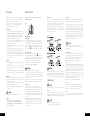
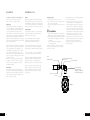
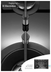
USER MANUAL
GHR16S, GHR16W, GHR17S,
GHR17W, GHR765S, GHR775S,
GHR95S, GHR95W, GHR795S
GAS COOKTOPS
congratulations
contents
Congratulations and thank you for choosing our Product.
We are sure you will find your new cooktop a pleasure
to use and a great asset to your cooking. Before you use
the cooktop, we recommend that you read through the
whole user manual which provides the description of the
cooktop and its functions.
Important safety instructions . . . . . . . . . . . . . . . . . . . . . 3
Installation and use summary . . . . . . . . . . . . . . . . . . . . . 4
Cleaning and care . . . . . . . . . . . . . . . . . . . . . . . . . . 5
Troubleshooting . . . . . . . . . . . . . . . . . . . . . . . . . . . 6
Installation instructions . . . . . . . . . . . . . . . . . . . . . . . 7
Installation procedure . . . . . . . . . . . . . . . . . . . . . . . . 8
Gas connection . . . . . . . . . . . . . . . . . . . . . . . . . . . 10
Operation on NG/SNG . . . . . . . . . . . . . . . . . . . . . . . . 10
LPG conversion . . . . . . . . . . . . . . . . . . . . . . . . . . . 12
Electrical connection . . . . . . . . . . . . . . . . . . . . . . . . . 13
Testing appliance operation . . . . . . . . . . . . . . . . . . . . . 14
Warranty . . . . . . . . . . . . . . . . . . . . . . . . . . . . . . . 15
To avoid the risks that are always present when you
use a gas appliance, it is important that the cooktop is
installed correctly and that you read the safety instructions
carefully to avoid misuse and hazards. For future reference,
please store this booklet in a safe place.
This appliance complies with the requirements of
Australian Standard AS 4551.
Conditions of Use
This appliance is intended to be used in household and
similar applications such as:
• Staff kitchen areas in shops, offices and other
working environments
• Farm Houses
• By clients in hotels, motels and other residential
type environments
• Bed and breakfast type environments.
Important safety instructions
Please read the user manual carefully and store in a
handy place for later reference. The symbols you will
see in this booklet have these meanings:
WARNING
This symbol indicates information concerning your personal safety
CAUTION
This symbol indicates information on how to avoid damaging
the appliance
TIPS & INFORMATION
This symbol indicates tips and information about use of the appliance
ENVIRONMENTAL TIPS
Children should be supervised to ensure they do
not play with this appliance.
During use, this appliance becomes hot. Care should
be taken to avoid touching hot surfaces. To avoid
burns, young children should be kept away.
This appliance must not be used as a space heater.
Keep vents clear of obstructions.
In order to avoid a fire, this appliance must be
kept clean.
Do not spray aerosols in the vicinity of this
appliance while it is in operation.
Do not store flammable materials in or under this
appliance, e.g. aerosols.
Meanings of symbols used in this manual are shown below:
Do not allow pots to boil dry, as damage to both
pan and cooktop may result.
This symbol indicates never to do this
Record model and serial number here:
TIPS & INFORMATION
Serial number: .......................................................
This appliance is not intended for use by persons
(including children) with reduced physical, sensory
or mental capabilities, or lack of experience
and knowledge, unless they have been given
supervision or instruction concerning use of the
appliance by a person responsible for their safety.
This symbol indicates tips and information about economical and
ecological use of the appliance
This symbol indicates always do this
Model: .................................................................
WARNING
Important – CHECK FOR ANY DAMAGE OR MARKS. If you find
the cooktop is damaged or marked, you must report it
within 7 days if you wish to claim for damage/marks
under the manufacturer’s warranty. This does not affect
your statutory rights.
Do not operate the cooktop for an extended period
of time without a pot or pan on the hotplate.
Do not allow large cookware to overhang the
cooktop onto the adjacent benchtop. This will
cause scorching to the benchtop surface.
Do not allow cooking pots or pans to intrude
into the area which is close to the controls.
Ensure burner caps and trivets are properly located.
(See Figure1)
For maximum stability, ensure pots and pans
are centrally located on the trivets.
Handles should be turned away from the front
of the bench to avoid accidents.
ENVIRONMENTAL TIPS
Information on disposal for users
•M
ost of the packing materials are recyclable.
Please dispose of those materials through your local
recycling depot or by placing them in appropriate
collection containers.
• If you wish to discard this product, please contact your
local authorities and ask for the correct method of disposal.
Do not modify this appliance.
Only models fitted with flame safeguard can be
used in marine craft, caravans or mobile homes.
Figure 1
1
2
3
4
1 Burner
2 Flame safeguard sensor
(where fitted)
CONTENTS
2
3 Injector
4 Ignition spark plug
3
SAFETY
installation
USING YOUR COOKTOP
NOTE: You must read these warnings carefully before
Note: Gas controls turn anticlockwise from ‘Off’ and
have limited movement.
installing or using the cooktop. If you need assistance,
contact your Customer Care Department.
The manufacturer will not accept liability, should the
instructions below or any other safety instructions
incorporated in this book be ignored.
installation
•An authorised person must install this appliance and
MUST provide a certificate of compliance. This certificate
should be retained along with purchase information.
•Before using the appliance, ensure that all packing
materials are removed from the appliance.
•In order to avoid any potential hazard, the installation
instructions in this booklet, and any labels on the
appliance must be followed.
•Ensure that all specified vents, openings and air spaces
are not blocked.
•Where the appliance is built into a benchtop, the
benchtop material must be capable of withstanding 85°C.
•Ensure that the duplicate rating label (in the instruction
pack) is attached to a readily-accessible adjacent surface,
so that the cooktop can be easily identified in the case
of a service call.
SERVICING
•Servicing MUST only be carried out by authorised
personnel.
•To maintain safe operation, it is recommended that the
product be inspected every five years by an authorised
service person.
• If the supply cord is damaged, it must be replaced by an
authorised service person in order to avoid a hazard.
CLEANING
•Always ensure the appliance is turned off before cleaning.
•This appliance contains aluminium fittings. Do not use
caustic-based cleaners.
•Do not use steam cleaners, as this may cause moisture
build up on electrical components.
•Always clean the appliance immediately after any
food spillage.
CAUTION
•DO NOT place burners in a dishwasher.
CONTROLS
•Each burner is controlled by a control knob.
The markings on the control panel indicate which
burner the knob controls, and the settings for that
burner. (See Figure 2)
INSTALLATION & USE
4
Figure 2
Pots and pans
All common pots and pans: aluminium, stainless steel,
cast iron, ceramic, etc., may be used on your new gas
model cooktop. Ensure that the pots or pans are steady
and have flat bases to avoid dangerous spill-over of
hot liquids and wasted energy. A wok support has been
supplied with this appliance for use when cooking with
a round-bottom wok. The support is not necessary when
cooing with a flat-bottom wok.
Figure 3
LIGHTING BURNERS
Electronic ignition
These cooktops are fitted with mains powered ignition.
When the appliance has been connected and the power
is on, depressing any knob will release sparks to all burners.
To light a burner, depress the corresponding knob and
turn to the ‘High’ position (while depressing the knob).
The knob may be released once the flame is established.
• Keep hands clear of burners when lighting.
• If burner does not light within 5 seconds, turn knob to ‘Off’
position, allow gas to disperse, then try lighting again.
• Burners MUST be operated between ‘HIGH’ and ‘LOW’
settings only.
In the absence of electrical power, carry out the ignition
directly to the burner with a hand-held ignition source.
Choice of burners
For your convenience there is a choice of burners:
• A small burner for special low heat and slow cooking.
•A medium burner for normal cooking and simmering.
(one on 4-burner models and two on 5-burner models).
•A large burner for fast heating and large pots and pans.
•A wok burner for very fast heating using a wok or large
pot or pan.
To conserve gas, place the pan centrally over the burner
and adjust the flame so that it does not extend past the
edge of the pan (Figure 3). Do not boil food too rapidly.
A vigorous boil will not cook food any faster, and will
waste energy.
All grades of stainless steel may stain, discolour or attain
an adhering layer of grime in normal operation. To achieve
maximum surface appearance, stainless steel must be kept
clean by regularly using the following cleaning procedures,
thus ensuring good performance and long service life.
Wash with warm soapy water and rinse with clean water.
Where the stainless steel has become extremely dirty with
signs of surface discolouration, (due to periods of neglect
or misuse) use a stainless steel cleaner.
CAUTION
DO NOT use abrasive scourers or steel wool.
When removing these stains be sure to follow the polish
or brushing lines.
Flame safeguard models
The knob must be turned to the ‘High’ position,
then pushed down as far as possible for approximately
5 seconds. If the flame goes out when the knob is released,
simply depress the knob again, this time holding it down
with slightly more force for the same length of time.
The height of the flame can be varied by turning the
control knob toward the ‘Low’ position.
WARNING
Stainless steel
Note: Ensure any oil is cleaned off the hob before first use,
otherwise it may cause the hob to turn a yellowish colour.
WARNING
Never use asbestos mats, wire mats or grids, aluminium foil
as it can lead to overheating, cracked enamel. The warranty
will be void if these items are used and cause a failure. Woks
should only be used on the wok burner and wok support trivet.
CLEANING & CARE
CAUTION
Ensure the appliance is off and cool before cleaning.
Enamel
Persistent stains may require rubbing with a nylon scourer or
creamed powder cleansers. Household enamel cleaners are
available, follow the manufacturer’s instructions in their use.
Trivets and burners
These can all be lifted off and removed for separate cleaning.
This appliance is fitted with single-piece burners (except
triple ring wok burner) for ease of cleaning. The burners
and trivets are removable for easy cleaning.
Note: When refitting the burners, ensure that they are
correctly seated.
Ensure burners are thoroughly dried after cleaning or spillage.
When cleaning the burners, ensure that all the flame ports
are free of any blockage. If necessary, use a toothpick or
brush to clear ports. The outer surface of the burners have
a polished finish and extra care needs to be taken to avoid
scratching this surface during cleaning. In instances of heavy
soiling, it may be necessary to apply a non-abrasive cleaning
compound and rub with a cloth until the soiling is removed
and then finish with a soft, dry cloth.
Note: DO NOT place burners in the dishwasher.
Ignition
GENTLY clean the spark plug and flame safe guard
sensor (where fitted) with a damp cloth to avoid lighting
difficulties. Ensure the electrode is dry before use.
Injector
Ensure the injector remains free of any foreign material.
If necessary, use a thin piece of wire to clear the orifice.
CAUTION
Harsh abrasive cleaners, powder cleaners,
steel wool or wax polishes should not be used.
5
CLEANING & CARE
INSTALLATION INSTRUCTIONS
If you have a problem with the cooktop, check the table below. You may be able to solve the problem and this will
save you from paying for a service call. You will have to pay for a service call even in the warranty period if the
problem is one listed below.
FAULT
possible causes
• Knob not held down long enough
Burner will not light
in ‘High’ position for flame safeguard
even though the sparker
(where fitted) to engage
is working.
REMEDY
• Repeat lighting procedure and hold knob
down for 5 seconds in ‘High’ position
(refer page 4)
• Gas supply valve turned off
• Turn on gas supply to appliance
• Wrong knob turned
• Ensure the knob you are turning corresponds
to the burner you want to light
• Port blockage in ignition area
• Ensure that ports in ignition area are clean
and dry
• Ignition spark plugs wet or dirty
• Dry or clean ignition spark plugs
No spark is obtained
when control knob
is activated
• Electricity supply is disconnected or
switched off
• Switch on electricity or check fuses
• Ignition spark plugs wet or dirty
• Dry or clean ignition spark plugs
Flames uneven or
tending to lift
• Flame ports blocked or wet
• Clean or dry flame ports
• Burner incorrectly fitted
• Ensure this component is fitted correctly
Flames not staying on
when knob released
• Knob not held down long enough
in ‘High’ position for flame safeguard
(where fitted) to engage
• Repeat lighting procedure and hold knob
down for 5 seconds in ‘High’ position
(refer page 4)
• Knob not set between ‘High’ and
‘Low’
• Knob MUST be set between these positions.
• Dirt or spillage on flame safeguard
sensor (where fitted)
• Clean flame safe guard sensor tip
Low heat, slow cooking
• Incorrect cooking pot or pan being used • Refer to Figure 3 (page 5)
Benchtop or knobs
overheating
• Incorrect cooking pot or pan used
• Check Figure 3 for correct pot or pan to be used
• P ot or pan not located on burner
properly
• Ensure pot or pan is centrally located
on burner
This appliance must be installed by an authorised person
and in compliance with :
1.AS/NZS 5601.1 Gas Installations Part 1: General
Installations, and AS/NZS 5601.2 Gas Installations
Part 2: LP Gas installations in caravans and
boats for non-propulsive purposes, or the relevant
installation code for gas appliances in your country.
2.The local gas fitting regulations, municipal building
codes, electrical wiring regulations and any other
relevant statutory regulations.
3.The particular instructions as given below.
CAUTION
Cooktops are supplied for use with natural gas (NG).
To use on LPG the injectors MUST be changed using
the conversion kit supplied. Refer LP Conversion on
page 12.
4.A certificate of compliance MUST be given to the
customer after the appliance is successfully installed.
5.This appliance must be earthed.
Figure 4–60cm and 75cm models cut-out
Gas supply connection location
*
560mm
480mm
Figure 4–90cm models cut-out
If the above points have been checked and there is still a problem with the cooktop, please call the Service Centre.
Gas supply connection location
*
830mm
TROUBLESHOOTING
6
480mm
7
INSTALLATION
INSTALLATION PROCEDURE
1.The bench cutout should be made as per cutout
dimensions in Figure 4.
2.Adjacent walls, cupboards and protection for
combustible materials.
Ensure that the appliance is installed in accordance
with clauses 6.2.5 and 6.10.1.1 of AS/NZS
5601.1, or clauses 6.9.1 and 6.9.5 of AS/NZS
5601.2 with regard to clearances to combustible
surfaces and materials, and clearances to
rangehoods and exhaust fans.
To ensure clearances of 200mm from burners to
vertical combustible surfaces observe the minimum
dimensions shown in Figure 5.
Clearances to combustible surfaces may be reduced
if combustible surfaces are protected in accordance
with clause 6.10.1.2 of AS/NZS 5601.1, or clause
6.9.2 of AS/NZS 5601.2.
3.Optional Barrier
A barrier can be installed to prevent accidental contact
with the cooktop base, where the base of the cooktop
is accessible from below (i.e. inside a cupboard, etc).
An impression has been incorporated into the base to
ensure a minimum clearance of 15mm is maintained
between the base and the barrier. This barrier may
be made of any non-combustible, rigid material.
4.Fitting the cooktop into the bench
Carry out as follows:
• Place the seals supplied around the bench cut-out
as shown in Figure 6, taking care that the seals
meet without overlapping.
• Fit the pull-down clamps supplied to ensure
that the cooktop cannot move after installation.
WARNING
Failure to fix the cooktop to the bench could result
in loosening of the gas connection through movement
of the cooktop and a gas leak may result.
•U
se the 4 clamps and screws supplied in the parts
bag for 4 burner models, and 6 clamps and screws
for 5 burner models.
• To assemble, attach the clamps to each corner
of the burner box via the screws provided.
• Fix the clamps as shown in Figure 7. The clamp
location points are shown in Figure 8.
• Remove excess seal.
• If the benchtop is less than the standard 33mm
thickness, use a packer between the bench and
the pull down clamps to ensure the cooktop is
properly secured.
INSTALLATION
8
Figure 5–60cm models
combustible surface
Figure 7
Figure 6–60cm models
seal
hob
trivet
benchtop
131mm
10mm
clamp
burner box
screw
131mm
Figure 5–75cm models
11mm
119mm
Figure 8–60cm and 75cm models
11mm
clamp location
clamp location
Figure 6–75cm models
combustible surface
131mm
10mm
91mm
Figure 5–90cm models
86mm
79mm
combustible surface
clamp location
86mm
Bottom view
clamp location
Figure 8–90cm models
Figure 6–90cm models
possible clamp locations
131mm
10mm
111mm
99mm
26mm
26mm
possible clamp locations
Bottom view
9
INSTALLATION
GAS CONNECTION
OPERATION ON N.G./S.N.G.
This appliance is supplied for use with Natural Gas.
Regulator
An appliance regulator is provided. The regulator must be
positioned so that the pressure test nipple is accessible
when the appliance is installed. Connect the gas supply
to the ½” B.S.P. internal thread inlet of the regulator. Refer
to ‘bench cutout’ (Figure 4) for connection point position.
However, it can be converted for use with LPG.
Refer to LP conversion on pages 12 and 13.
Supply pipe sizing
The total hourly gas consumption for the appliance is
shown on the data label. The required supply pressure
(i.e. at inlet to appliance regulator) for each gas type
is shown on the data label, and given in Table 2.
Use this information in conjunction with the length of run,
number of elbows, tees and bends, the available service
pressure and the supply requirements of other installed
appliances to determine a suitable pipe size. For assistance
in this matter refer to the appropriate section of AS/NZS
5601.1 or AS/NZS 5601.2.
An AGA certified class B or D flexible connection may be
used to connect the cooktop in accordance with AS/NZS
5601.1, in particular section 5.9 and clause 6.10.1.8,
or AS/NZS 5601.2, in particular section 2.11. Where
a hose assembly is used and the cooktop is in the
installed position, the hose assembly shall be suitable for
connection to a fixed consumer piping outlet located at
a point 800 – 850mm
above the floor and in the region outside the width of
the appliance to a distance of 250mm. The point of
connection to consumer piping must be accessible
with appliance installed.
Elbow positioning
It is possible to reposition the elbow if required by
loosening the locking nut and elbow by using two spanners.
Re-tighten the entire assembly after the elbow has been
repositioned. When fitting elbow to appliance, ensure
that the sealing washer is fitted.
Assembly of Regulator
The assembly of the regulator to the cooktop manifold
is achieved via the elbow union and sealing washer
supplied, refer to figure 9 (page 11).
The ½” parallel thread connects to the manifold,
and the sealing washer is placed between the
manifold end and the flat face on the elbow.
The ½” tapered thread connects to the outlet of the
regulator, and is sealed on the thread using approved
thread sealing tape or approved thread sealing compound.
Checking the gas supply
1.Check the manometer zero point is correct.
2.Connect the manometer to the cooktop pressure point.
This is located on the regulator.
3.Turn on the gas supply and electricity and try to ignite
the gas.
TIPS & INFORMATION
NOTE! It will take additional time to light the gas for
the first time as air needs to be purged from the pipes.
4.With the appliance operating check the outlet pressure
•w
hen all burners of the appliance are operating
at maximum,
•when the smallest burner of the appliance
is operating at minimum.
Under these conditions the outlet pressure should not
vary from the nominal outlet pressure of 1.00kPa by
more than +/– 0.20kPa.
If the regulator appears to not be performing satisfactorily,
then check the following points.
1.If the outlet pressure is consistently too low then the
inlet pressure may be too low and adjustment of an
upstream regulator may be needed, or an upstream
regulator or valve with insufficient flow capacity may
be present in the gas supply line. If this is suspected
then it may be necessary to repeat the checks whilst
measuring both the inlet and outlet pressure to determine
if the inlet pressure is in the range 1.13 – 5kPa.
2.Check that the regulator has been fitted to the gas
supply line in the correct orientation, the arrow on the
base of the body indicates the direction of gas flow.
Once these checks have been completed, if the
regulator still fails to perform in a satisfactory manner
it should be replaced.
The inlet of the regulator is a ½” parallel thread and
is connected to consumer piping or hose assembly.
Regulators are supplied pre-adjusted and configured
by the component maker for use with Natural Gas.
The appliance installer is not required to make an
adjustment to obtain the correct outlet pressure setting.
An arrow on the base of the regulator indicates the
direction of gas flow when the inlet and outlet of the
regulator is orientated correctly. When the regulator
has been fitted check for leaks from the connections
with soapy water.
Figure 9
Sealing washer
Manifold endform
½” Parallel thread
½” Tapered thread
Seal using approved
sealing tape or approved
thread sealing compound
Female nut
Flat face
Outlet
Regulator
Inlet
GAS CONNECTION
10
11
GAS CONNECTION
ELECTRICAL CONNECTION (220-240 volts)
CAUTION
This appliance is fitted with Natural Gas burner injectors.
Please follow the procedure below if a conversion to suit
LP gas is required.
The conversion kit contains appropriate LPG injectors and
1 LPG sticker.
To convert to LPG
1.Remove the hotplate burners to access the hotplate
injectors. Replace the factory fitted NG injectors with
the appropriate injectors, as supplied (see Table 2).
2.Unscrew the hex nut from the regulator. The hex nut,
brass washer and nylon insert will disengage as
an assembly.
3.Unclip the nylon insert from the nut assembly
by rotating the insert ¼ turn, and pulling it free.
4. Turn over the insert, and clip back into position.
5.Refit the hex nut assembly to the regulator ensuring
that it is fully screwed down. The regulator is now
set for connection to LP.
6.Turn on the gas supply and at each new connection
check for leaks using soapy water: each hotplate
valve should be turned on, one at a time, and the
injector hole blanked off for several seconds.
7.The operation of the regulator can be confirmed by
connecting a manometer to the pressure test point
located on the side of the regulator body adjacent
to the outlet. With the appliance operating check
the outlet pressure
• when all burners of the appliance are operating
at maximum,
• when the smallest burner of the appliance
is operating at minimum.
Under these conditions the outlet pressure should not
vary from the nominal outlet pressure of 2.60kPa by
more than +/– 0.52kPa.
8.If the regulator appears to not be performing
satisfactorily then check the following points.
• If the outlet pressure is consistently too low then
the inlet pressure may be too low and adjustment
of an upstream regulator may be needed, or
an upstream regulator or valve with insufficient
flow capacity may be present in the gas supply
line. If this is suspected then it may be necessary
to repeat the checks whilst measuring both the
inlet and outlet pressure to determine if the inlet
pressure is in the range 2.75–7.00kPa.
• Check that the insert has been fitted correctly as
per diagram figure 10. Check that the hex nut is
fully screwed down.
• Check that the regulator has been fitted to the
gas supply line in the correct orientation, the arrow
on the base of the body indicates the direction of
gas flow.
Once these checks have been completed, if the
regulator still fails to perform in a satisfactory manner
it should be replaced.
9.One by one, turn the knobs to minimum and screw
in the bypass screw (accessible when the knob is
removed – refer figure 12) until a small stable flame
results. Turn the knob to maximum and then back to
minimum to ensure that the correct minimum flame
is maintained.
10. Attach the LPG sticker to the cooker, near the gas
supply inlet. Cover the Natural Gas label that is
factory fitted.
Figure 10
Hex nut assembly,
fully screwed down
Hex nut assembly,
removed from
regulator and insert
disassembled
LPG CONVERSION
LPG
(Nominal test point pressure: 2.60kPa)
BURNER TYPE
Injector size (mm)
Gas consumption (MJ/h)
Injector size (mm)
Gas consumption (MJ/h)
Small burner
1.00
5.1
0.55
4.2
Medium burner
1.35
9.0
0.70
6.5
Large burner
1.60
12.1
0.90
10.7
Wok burner
1.75
14.4
1.00
13.0
12
Diagram 1 is a schematic of the wiring in the appliance.
The weight of the unit is printed on the appliance
packaging label.
Diagram 1
E
N
L
Insert oriented for
natural gas operation
Table 2
natural gas
(Nominal test point pressure: 1.00kPa)
The appliance is supplied with a standard 7.5Amp
service cord terminated by a 3-pin plug for connection
to a standard household socket. The electrical supply
is required to power the electronic ignition system.
NOTE: It will be necessary for servicing purposes to
disconnect the electrical power supply. The power point
should therefore be accessible after the appliance is
installed, as specified in the local wiring regulations.
Insert oriented for
LPG operation
Use of Hose Assemblies
Ensure that the hose assembly is restrained from accidental
contact with the flue outlet of an underbench oven or any
other hot surface of an adjacent appliance.
13
ELECTRICAL
CONNECTION
Warranty
FORSALESINAUSTRALIAANDNEWZEALAND
APPLIANCE:BUILT-INOVEN,COOKTOP
ANDFREESTANDINGCOOKER
This document sets out the terms and conditions of the product
warranties for Electrolux Appliances. It is an important document.
Please keep it with your proof of purchase documents in a safe place
for future reference should you require service for your Appliance.
1. Inthiswarranty
6. Proofofpurchaseisrequiredbeforeyoucanmakeaclaimunder
thiswarranty.
(a) ‘acceptablequality’asreferredtoinclause10ofthiswarrantyhas
thesamemeaningreferredtointheACL;
Servicing must only be carried out by an authorised
service person.
(b) ‘ACL’meansTradePracticesAmendment(AustralianConsumer
Law)Act(No.2)2010;
(c) ‘Appliance’meansanyElectroluxproductpurchasedbyyou
accompaniedbythisdocument;
Injector sizes required for various gas types are shown in
Table 2 (page 11). The appliance inlet pressure for each
gas type is also shown.
For model identification after installation, an additional
data plate sticker has been provided. This sticker is to
be stuck onto adjacent cabinetry.
(d) ‘ASC’meansElectrolux’authorisedservicedcentres;
(e) ‘Electrolux’meansElectroluxHomeProductsPtyLtdof163
O’RiordanStreet,Mascot,NSW2020,ABN51004762341in
respectofAppliancespurchasedinAustraliaandElectrolux(NZ)
Limitedof3-5NiallBurgessRoad,MountWellington,inrespect
ofAppliancespurchasedinNewZealand;
(a)
(f) ‘majorfailure’asreferredtoinclause10ofthiswarrantyhasthe
samemeaningreferredtointheACLandincludesasituationwhen
anAppliancecannotberepairedoritisuneconomicforElectrolux,at
itsdiscretion,torepairanApplianceduringtheWarrantyPeriod;
(b) theApplianceismodifiedwithoutauthorityfromElectroluxinwriting;
(c) theAppliance’sserialnumberorwarrantysealhasbeenremoved
ordefaced;
(d) theAppliancewasservicedorrepairedbyanyoneotherthan
Electrolux,anauthorisedrepairerorASC.
TESTING APPLIANCE OPERATION
After installation, test the appliance and ensure that it
operates correctly before handing it over to the customer.
The following procedure is recommended:
1.Turn on the gas and electricity supply and attempt
ignition on all burners, both separately and in
combination. (For correct procedure, refer to page 4).
Note that additional time needs to be allowed for the
initial lighting as air has to be purged from the pipes.
2.Observe the flame appearance on each burner.
(Figure 11) If it is much larger or much smaller than
expected, the injector size and supply pressure
require checking. Where a flame is unsatisfactory,
refer to the Troubleshooting Guide (Page 6) to correct
the fault. If the Troubleshooting Guide does not solve
the problem, call the Service Centre.
3.When all the foregoing is satisfactory, check the
turndown (minimum or low) setting on each burner,
as this may need adjustment. Valves have a by
pass controlling screw, which may be accessed
by removing the knob. This screw will be located
on a particular area of the valve. (Refer figure 12).
Normally, this will have been correctly set at the
factory for use on NG (Natural Gas) and should not
require adjustment.
If the appliance has been converted to LPG, then the
bypass screw will have to be screwed in until a small,
stable flame results.
Please ensure the supply pressure has been checked
PRIOR to any adjustment.
4.If the appliance cannot be adjusted to perform safely,
inform the customer of the problem and affix an
appropriate warning notice to the appliance. If the
fault appears to be dangerous the appliance should
be disconnected. If a minor fault exists, the customer
may wish to use the appliance while awaiting service.
If a fault cannot be fixed, please call the Service Centre.
5.The customer should be advised that, in the event
of a fault, the local Service Organisation or the
retailer from whom the appliance was purchased
should be contacted.
6.When satisfied that the unit is operating correctly, turn off
and instruct the customer on correct operation as outlined
in this booklet. Ask the customer to operate the controls
to ensure that the correct procedure is understood.
WARNING
Figure 11
Flame size adjusted to maximum
(g) ‘WarrantyPeriod’means:
(i) w
heretheApplianceisusedforpersonal,domesticorhousehold
use(i.e.normalsinglefamilyuse)assetoutintheinstruction
manual,theApplianceiswarrantedagainstmanufacturing
defectsinAustraliafor24monthsandinNewZealandfor24
months,followingthedateoforiginalpurchaseoftheAppliance;
(ii) w
heretheApplianceisusedforcommercialpurposes(including
beingusedtodirectlyassistabusinessorwheretheApplianceis
usedinamulti-familycommunalorsharetypeenvironment),the
Appliancewillthenbewarrantedagainstmanufacturingdefects
inAustraliafor3monthsandinNewZealandfor3months,
followingthedateoforiginalpurchaseoftheAppliance.
Flame size adjusted to minimum
(h) ‘you’meansthepurchaseroftheAppliancenothavingpurchased
theApplianceforre-sale,and‘your’hasacorrespondingmeaning.
2. T
hiswarrantyonlyappliestoAppliancespurchasedandusedinAustralia
orNewZealandandisinadditionto(anddoesnotexclude,restrict,or
modifyinanyway)anynon-excludablestatutorywarrantiesinAustralia
orNewZealand.
3. D
uringtheWarrantyPeriodElectroluxoritsASCwill,atnoextracharge
ifyourApplianceisreadilyaccessibleforservice,withoutspecial
equipmentandsubjecttothesetermsandconditions,repairorreplace
anypartswhichitconsiderstobedefective.ElectroluxoritsASCmay
useremanufacturedpartstorepairyourAppliance.Youagreethat
anyreplacedAppliancesorpartsbecomethepropertyofElectrolux.
Thiswarrantydoesnotapplytolightglobes,batteries,filtersorsimilar
perishableparts.
Figure 12
Bypass screw
4. P
artsandAppliancesnotsuppliedbyElectroluxarenotcoveredby
thiswarranty.
5. Y
ouwillbearthecostoftransportation,travelanddeliveryofthe
AppliancetoandfromElectroluxoritsASC.Ifyouresideoutsideofthe
servicearea,youwillbearthecostof:
7. Y
oumaynotmakeaclaimunderthiswarrantyunlessthedefectclaimed
isduetofaultyordefectivepartsorworkmanship.Electroluxisnotliable
inthefollowingsituations(whicharenotexhaustive):
theApplianceisdamagedby:
(i) accident
(ii) misuseorabuse,includingfailuretoproperlymaintainorservice
(iii) normalwearandtear
(iv) powersurges,electricalstormdamageorincorrectpowersupply
(v) incompleteorimproperinstallation
(vi) incorrect,improperorinappropriateoperation
(vii)insectorvermininfestation
(viii)failuretocomplywithanyadditionalinstructionssuppliedwith
theAppliance;
8. T
hiswarranty,thecontracttowhichitrelatesandtherelationship
betweenyouandElectroluxaregovernedbythelawapplicablewhere
theAppliancewaspurchased.WheretheAppliancewaspurchasedin
NewZealandforbusinesspurposestheConsumerGuaranteeActdoes
notapply.
9. T
otheextentpermittedbylaw,Electroluxexcludesallwarrantiesand
liabilities(otherthanascontainedinthisdocument)includingliabilityfor
anylossordamagewhetherdirectorindirectarisingfromyourpurchase,
useornonuseoftheAppliance.
10.ForAppliancesandservicesprovidedbyElectroluxinAustralia,
theAppliancescomewithaguaranteebyElectroluxthatcannotbe
excludedundertheAustralianConsumerLaw.Youareentitledtoa
replacementorrefundforamajorfailureandforcompensationforany
otherreasonablyforeseeablelossordamage.Youarealsoentitledto
havetheAppliancerepairedorreplacediftheAppliancefailstobeof
acceptablequalityandthefailuredoesnotamounttoamajorfailure.
Thebenefitstoyougivenbythiswarrantyareinadditiontoyourother
rightsandremediesunderalawinrelationtotheAppliancesorservices
towhichthewarrantyrelates.
11.AtalltimesduringtheWarrantyPeriod,Electroluxshall,atitsdiscretion,
determinewhetherrepair,replacementorrefundwillapplyifan
Appliancehasavalidwarrantyclaimapplicabletoit.
12.ForAppliancesandservicesprovidedbyElectroluxinNewZealand,
theAppliancescomewithaguaranteebyElectroluxpursuanttothe
provisionsoftheConsumerGuaranteesAct,theSaleofGoodsActand
theFairTradingAct.
13.Toenquireaboutclaimingunderthiswarranty,pleasefollowthesesteps:
(a) c
arefullychecktheoperatinginstructions,usermanualandtheterms
ofthiswarranty;
(b) havethemodelandserialnumberoftheApplianceavailable;
(a) travelofanauthorisedrepresentative;
(c) havetheproofofpurchase(eganinvoice)available;
(b) transportationanddeliveryoftheAppliancetoandfrom Electroluxor
itsASC,
(d) telephonethenumbersshownbelow.
Inallinstances,unlesstheApplianceistransportedbyElectroluxoran
Electroluxauthorisedrepresentative,theApplianceistransportedatthe
owner’scostandriskwhileintransittoandfromElectroluxoritsASC.
14.Youacceptthatifyoumakeawarrantyclaim,ElectroluxanditsASC
mayexchangeinformationinrelationtoyoutoenableElectroluxtomeet
itsobligationsunderthiswarranty.
Important Notice
Beforecallingforservice,pleaseensurethatthestepslistedinpoint13abovehavebeenfollowed.
FOR SERVICE
ortofindtheaddressofyournearest
stateservicecentreinAustralia
PLEASE CALL 13 13 49
Forthecostofalocalcall(Australiaonly)
FOR SERVICE
ortofindtheaddressofyournearest
authorisedservicecentreinNewZealand
FREE CALL 0800 10 66 10
(NewZealandonly)
SERVICE AUSTRALIA
ELECTROLUXHOMEPRODUCTS
www.electrolux.com.au
SERVICE NEW ZEALAND
ELECTROLUXHOMEPRODUCTS
www.electrolux.co.nz
FOR SPARE PARTS
ortofindtheaddressofyournearest
statesparepartscentreinAustralia
PLEASE CALL 13 13 50
Forthecostofalocalcall(Australiaonly)
FOR SPARE PARTS
ortofindtheaddressofyournearest
statesparepartscentreinNewZealand
FREE CALL 0800 10 66 20
(NewZealandonly)
GOV_Warr_Apr11
TESTING APPLIANCE
OPERATION
14
15
WARRANTY
For more information on all Westinghouse appliances,
or for dimension and installation information, call into your retailer,
phone or email our customer care team or visit our website:
AUSTRALIA
phone: 1300 363 640
fax:
1800 350 067
email:[email protected]
web:www.westinghouse.com.au
NEW ZEALAND
phone: 09 573 2384
fax:
0800 363 600
email:[email protected]
web:www.westinghouse.co.nz
TOP SERVICE
Top Service encompasses the after sales service
provided by The Electrolux Group to consumers
including delivery, home service and spare parts.
Westinghouse. We are part of the Electrolux family.
Share more of our thinking at www.electrolux.com
Part number: 305 4423 02 Rev D
© 2011 Electrolux Home Products Pty Ltd ABN 51 004 762 341
Print code: WMANIGCTUM_Jun11