1
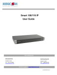
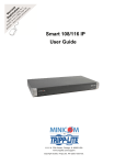
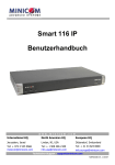
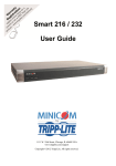
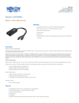
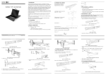
SMART 108 / 116 IP
2. System components
The system consists of:
•
Smart 108 / 116 IP - Quick Start Guide
1 Smart 116 IP (p/n 0SU60005) or 1 Smart 108 IP (p/n 0SU70032
•
Rack mounting set (p/n 5AC20247)
•
1 RS232 Download cable (p/n 5CB40419)
•
ROCS - PS/2, USB. (Ordered separately). CAT5 cables (1.5m provided)
3. Compatibility
The Smart 116 IP is compatible with:
•
PS/2, SUN and USB computers/servers
•
VGA, SVGA, or XGA monitors
•
Windows, Linux, UNIX and other major operating systems
4. The Smart 116 IP unit
Figure 1 illustrates the front panel of the Smart 116 IP.
SMART 116 IP
MINICOM
1. Introduction
Power
To take advantage of the full range of features, we recommend you read the softcopy
User Guide after performing the Quick Start procedure. It’s in PDF format
on the supplied CD or on our website www.minicom.com in the Support section.
All references throughout this guide to the Smart 116 IP refer equally to the Smart
108 IP. The two units are functionally the same. The Smart 116 IP has 16 Server
ports and the Smart 108 IP has 8 Server ports.
The Smart 116 IP extends your KVM (keyboard, video, and mouse) from any
computer or server over TCP/IP via LAN, WAN or Internet connection. Now you
can control, monitor and manage up to 16 remote servers from wherever you are,
inside or outside the organization. The Smart 116 IP is a cost-effective hardware
solution, for secure remote KVM access & control of 16 computers/servers from
the BIOS level - independent of the OS. One local analog or one remote digital IP
user can access and control 16 multi-platform (PS/2, SUN, USB) servers.
Remote
Link
Local
Reset
Figure 1 Smart 116 IP front panel
4.1 LED and button table
LED
Function
Power
Power Indicator
Remote
Illuminates when remote session is active
Link
Unit is connected to the network
Button
Function
Local
When pressed, Smart 116 IP disconnects the Client remote session
and the local mouse and keyboard become operational. The Remote
LED turns off.
Reset
Press and hold for more than 7 seconds to reset the Smart 116 IP unit
Technical support - [email protected]
© 2009 Copyright Minicom Advanced Systems. All rights reserved.
5UM21166 V1 12/09
1
SMART 108 / 116 IP
QUICK START GUIDE
Figure 2 illustrates the rear panel of the Smart 116 IP. The Smart 108 IP has 8
Server ports.
6. Connecting the system
Figure 3 illustrates the Smart 116 IP system overview.
Monitor
SERIAL
I
0
SERIAL
I
0
10
11
12
13
14
15
FLASH
LAN
1
10
2
11
3
12
4
13
5
14
15
6
16
7
8
To LAN port
FLASH
Mouse
9
CONSOLE
POWER
100- 240V AC 50/6 0 Hz
16
CONSOLE
POWER
100-240 VAC 50/60 Hz
Power
connector
9
LAN
1
2
3
Flash
(download) LAN (Ethernet)
connector connector
4
5
6
7
8
Server ports
Keyboard
Remote User
To servers
Figure 2 Smart 116 IP rear panel
Internet / VPN / LAN
ROCs
4.2 Connector table
Connector
Function
Console KVM
(Optional) Connect a keyboard, video and mouse to operate the Smart
116 IP locally
This port is for future Serial functionality
Serial
Flash
To update firmware of the analogue part of the Smart 116 IP system OSD, Switch, RICCs and RoCs.
LAN
Connect to 10/100 Mbit Ethernet. Green LED illuminates when unit is
connected to a 100 Mbit/sec network. Yellow Led illuminates when unit is
connected to a 10 Mbit/sec network.
Server ports
Connect to servers via RICC/ROCs
5. Pre-installation guidelines
•
Place cables away from fluorescent lights, air conditioners, and machines that
are likely to generate electrical noise
•
Place the Smart 116 IP on a flat, clean and dry surface
•
The Smart 116 IP is not intended for connection to exposed outdoor lines
•
Ensure that the maximum distance between each computer and the Smart 116
IP, does not exceed 10m/33ft for RICCs and 30m/100ft for ROCs.
Figure 3 Smart 116 IP system overview
6.1 The ROCs
Each computer/server is directly connected to the Smart 116 IP via the appropriate
ROC using CAT5 cable in a star configuration. No external power is needed at the
remote ROCs. The ROCs draw their power from the computer’s keyboard port
(ROC PS/2) or from the USB port (ROC USB).
6.1.1 Connecting a ROC PS/2
You can connect the ROC PS/2 to a powered on computer, but it must be in the
following order. Failure to connect in this order while the server is running, may
lead to the mouse malfunctioning until the server is rebooted.
1. Connect the Mouse connector to the computer’s Mouse port.
2. Connect the Keyboard connector to the computer’s Keyboard port.
3. Connect the Screen connector to the computer’s Video port.
6.1.2 Connecting a ROC USB
The ROC USB supports Windows 98 SE and later, MAC, SUN and SGI, and all
modern Linux distributions.
To connect the ROC USB:
1. Connect the Screen connector to the computer’s Video port.
2. Connect the USB connector to the computer’s USB port.
2
3
QUICK START GUIDE
SMART 108 / 116 IP
8. Logging into the Web interface
6.2 Connecting to the network
Connect the network cable to the LAN port of the Smart 116 IP. This must be done
before powering on the Smart 116 IP.
6.3 Connecting the CAT5 cables
Client computer operating system. - Windows 2000 or higher, with Firefox 3 or
Internet Explorer 7.0 or later version. Linux with Firefox 3.
Complete the initial setup via the Web configuration interface:
1. Connect one connector to the RICC/ROCs RJ45 port.
2. Connect the other connector to one of the Smart 116 IP’s Computer ports.
3. Follow the above 2 steps for each computer.
1. Open your Web browser and type the Smart 116 IP system IP address https://IP address/ - and press Enter. The login page appears.
2. In mode select Configuration.
3. Type the default Administrator user name admin and password access (both
lower case).
6.4 Connecting the power supply
1. Using the Power cord provided, connect the Smart 116 IP to a socket outlet with
grounding connection. Only use the power cord supplied with the unit.
4. Press Enter. The Web interface opens at the Network Configuration page, see
Figure 4.
2. Switch on the Smart 116 IP.
7. Initial settings - Default IP address
The following sections provide instructions for setting the IP address for the Smart
116 IP unit.
By default, Smart 116 IP boots with an automatically assigned IP address from a
DHCP (Dynamic Host Configuration Protocol) server on the network. The DHCP
server provides a valid IP address, gateway address and subnet mask.
To identify the IP address, the Smart 116 IP MAC address appears on the underside
of the Smart 116 IP box. The device number (D.N.) can also be found there.
If no DHCP server is found on the network, Smart 116 IP boots with the static IP
address:192.168.0.155.
Note! If a DHCP server later becomes available, the unit picks up the IP settings
from DHCP server. To keep the static IP address, disable DHCP – explained in the
softcopy User Guide.
7.1 Static IP addresses for a number of units
Where you want to connect more than 1 Smart 116 IP to the same network and
there is no DHCP server, or you want to use static IP addresses, do the following:
Connect the Smart 116 IP units one at a time and change the static IP address of
each unit before connecting the next unit.
Figure 4 Smart 116 IP Web interface
9. The OSD
To display the OSD:
1. Ensure there is no remote user connected. To disconnect the remote user press
the Local button on the Smart 116 IP.
2. Press Shift twice. The OSD Main window appears. See Figure 5. Lines with
yellow text show active computers. Lines with blue text show inactive
computers. The Type column indicates a computer “C” is connected to the port.
4
5
SMART 108 / 116 IP
QUICK START GUIDE
The screen of the currently selected Target Server with Minicom toolbar appears
see Figure 6.
Port number
appears here
C=computer
Instruction
keys
Toolbar
Figure 5 OSD Main window
Server name
9.1 Navigating the OSD
To navigate up and down use the Up and Down arrow keys.
To jump from one column to the next (when relevant) use the Tab key.
To exit the OSD or return to a previous window within the OSD press Esc.
9.2 Selecting a computer
To select a computer:
1. Navigate to the desired computer line.
Or, type the port number of the desired computer.
2. Press Enter. The selected computer is accessed. A Confirmation label appears
showing which computer is accessed.
Figure 6 Remote console window
Note! When the OSD is displayed you cannot select computers using the keyboard
hotkeys.
10. Starting a remote session
At a Client computer open the web browser and type the Smart 116 IP’s IP address.
https://IP address. The Login page appears. Type your username and password and
press Enter. By default, the user name is: admin and the password is access, (both
lower case).
Note! There is a shortcut to the Configuration pages from the login page. Click the
arrow
to toggle between the option to access a remote session or the
configuration pages.
On first connection install the Minicom certificate and ActiveX control. You must
login as an Administrator to your computer to install the ActiveX control. Once the
ActiveX control is installed, all types of users can login.
When using a Firefox browser, install the Minicom Firefox add-on.
6
Locks Toolbar
Session Profile
Video Settings
Keyboard
Settings
Power Control Settings
(Currently not operational)
Mouse
Settings
Full Screen
Mode
Disconnect
Session
Target Switching Menu
Figure 7 Toolbar icons
10.1 Switching to a different server/device
To connect to a different server/device:
1. From the Toolbar, click
. A list of connected servers/devices appears.
2. Click the desired server. The screen of the server appears.
To complete the initial setup and log into the web interface please see the softcopy User
Guide on the supplied CD or on our website www.minicom.com in the Support section.
7