1
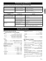
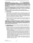
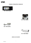
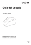
RLH
(NS-F40 + NS-C40 + NS-B40 + NS-SW40)
SPEAKER PACKAGE
OWNER'S MANUAL
MANUAL DE INSTRUCCIONES
Precautions
Please read the following operating precautions before use. Yamaha will not be held responsible for any damage and/or
injury caused by not following the cautions below.
1. To assure the finest performance, please read this
manual carefully. Keep it in a safe place for future
reference.
2. Install the speakers in a cool, dry, clean place – away
from windows, sources of heat, sources of excessive
vibration, dust, moisture or cold. Avoid sources of
electrical humming (e.g., transformers and motors). To
prevent fire or electric shock, do not expose the
speakers to rain or water.
3. To prevent the enclosure from warping or discoloring,
do not expose the speakers to direct sunlight or
excessive humidity.
4. Avoid installing the speakers where foreign objects may
fall onto them and/or where they may be exposed to
liquid dripping or splashing.
5. Do not place the following objects on top of the
speakers:
– Other components, as they might damage or discolor
the surface of the speakers.
– Burning objects (e.g., candles), as they might cause
fire, damage to the speakers or personal injury.
– Containers of liquid, as they might spill and cause
electric shock to the user or damage to the speakers.
6. Do not place the speakers where they are liable to be
knocked over or struck by falling objects. Stable
placement will also ensure better sound performance.
7. Placing the speakers on the same shelf or rack as the
turntable can result in feedback.
8. Any time you note distortion, reduce the volume control
on your amplifier to lower setting. Never allow your
amplifier to be driven into “clipping”. Otherwise, the
speakers may be damaged.
9. When using an amplifier with a rated output power
higher than the nominal input power of the speakers,
care should be taken not to exceed the maximum input
of the speakers.
10. When you clean the unit, use a clean, dry and soft cloth
(such as cloth for glasses).
11. Do not attempt to modify or fix the speakers. Contact
qualified Yamaha service personnel when service is
needed. The cabinet should never be opened for any
reason.
12. Be sure to read the “Troubleshooting” section regarding
common operating errors before concluding that the
speakers are faulty.
13. Secure placement or installation is the owner’s
responsibility. Yamaha is not liable for accidents
caused by improper placement or installation of
speakers.
For NS-SW40
WARNING
TO REDUCE THE RISK OF FIRE OR ELECTRIC
SHOCK, DO NOT EXPOSE THIS APPLIANCE TO
RAIN OR MOISTURE.
i En
1. Do not operate this unit upside down. It may overheat,
possibly causing damage.
2. Do not use excessive force on switches, controls or
connection wires. When moving this unit, first
disconnect the power plug and the wires connected to
other equipment. Never pull the wires themselves.
3. Never put a hand or a foreign object into the port
located on the right side of this unit. When moving this
unit, do not hold the port, as it might cause personal
injury and/or damage to this unit.
4. Since this unit has a built-in power amplifier, heat
radiates from the rear panel. Place the unit away from
walls, allowing at least 20 cm (8") of space above,
behind and on both sides of the unit to prevent fire or
damage. Furthermore, do not position the unit with the
rear panel facing down on the floor or other surfaces.
5. When using a humidifier, be sure to avoid condensation
inside this unit by allowing enough space around the
unit and avoiding excess humidification. Condensation
might cause fire, damage to the unit, and/or electric
shock.
6. Do not cover the rear panel of this unit with a
newspaper, tablecloth, curtain, etc. to avoid obstructing
heat radiation. If the temperature inside the unit rises, it
may cause fire, damage to the unit, or personal injury.
7. Do not plug this unit into a wall outlet until all
connections are complete.
8. The voltage to be used must match that specified on the
rear panel. Using this unit with a voltage higher than
specified is dangerous and may cause fire, damage to
the unit, and/or personal injury. Yamaha is not
responsible for damage resulting from use of this unit
with a voltage other than specified.
9. Super-bass sound reproduced by this unit may cause a
turntable to generate audio feedback. In this case, move
the unit away from the turntable.
10. This unit may be damaged if certain sounds are
continuously output at high volume level. For example,
if 20 Hz–50 Hz sine waves from a test disc or bass
sounds from an electronic instrument, etc. are
continuously output, or if a turntable stylus touches the
surface of a disc, reduce the volume level to prevent the
unit from being damaged.
11. If you hear distorted noise (i.e., unnatural, intermittent
“rapping” or “hammering” sounds) from this unit,
reduce the volume level. Extremely loud movie
soundtrack low frequency, bass-heavy sounds, or
similarly loud popular music passages can damage this
unit.
12. Vibration generated by super-bass sound may distort
images on a TV. In this case, move the unit away from
the TV set.
13. When disconnecting the power cord from the wall
outlet, grasp the plug; do not pull the cord.
14. When you plan not to use this unit for a long period of
time (i.e. vacation, etc.), disconnect the AC power plug
from the wall outlet.
15. Install this unit near the wall outlet and where the AC
power plug can be reached easily.
Precautions
This unit is not disconnected from the AC power
source as long as it is connected to the wall outlet, even
if this unit itself is turned off. In this state, this unit is
designed to consume a very small quantity of power.
For U.K. customers
If the socket outlets in the home are not suitable for the
plug supplied with this appliance, it should be cut off and
an appropriate 3 pin plug fitted. For details, refer to the
instructions described below.
Note: The plug severed from the mains lead must be
destroyed, as a plug with bared flexible cord is hazardous
if engaged in a live socket outlet.
SPECIAL INSTRUCTIONS FOR U.K. MODEL
IMPORTANT:
THE WIRES IN MAINS LEAD ARE COLOURED
IN ACCORDANCE WITH THE FOLLOWING
CODE:
Blue: NEUTRAL
Brown: LIVE
As the colours of the wires in the mains lead of this
apparatus may not correspond with the coloured
markings identifying the terminals in your plug,
proceed as follows: The wire which is coloured
BLUE must be connected to the terminal which is
marked with the letter N or coloured BLACK. The
wire which is coloured BROWN must be connected
to the terminal which is marked with the letter L or
coloured RED. Make sure that neither wire is
connected to the earth terminal of a three pin plug.
For Canadian Customers
To prevent electric shock, match wide blade of plug
to wide slot and fully insert.
This Class B digital apparatus complies with
Canadian ICES-003.
Caution
The speaker is constructed
with the majority of the
weight located in its upper
portion, and is thus
susceptible to falling over if
proper care is not taken to
ensure its stability. If the
speaker tips over, the speaker
or other personal property
may be damaged or an individual may be injured
(possibly even fatally injured).
For safe and proper use of the speaker:
• Position the speaker in a location that is solid, level,
smooth, and low (with respect to the floor).
• Do not push or apply pressure to the side of the
speaker when moving, or lean objects against the
side of the speaker.
• Do not sit on or set objects on top of the speaker.
Vibrations or jolts associated with earthquakes and
other phenomena or activities may cause the speaker to
fall over. For safety reasons, using commerciallyavailable products that increase stability of the speaker
is recommended (metal fittings or chains, etc.).
Contents
Package contents................................................1
Assembling the front speakers ........................1
Installing the speakers.......................................3
Installing the front, center, and surround
speakers ...........................................................3
Installing the subwoofer.......................................3
Wall-mounting the speakers................................3
Connecting the speakers .................................. 4
Connection diagram.............................................4
Connecting the power cables ..............................6
Using the Subwoofer ......................................... 6
Setting the subwoofer volume .............................6
Troubleshooting ................................................. 7
Specifications...................................................... 7
If this product doesn’t work as expected, look for a possible cause in the troubleshooting section on page 7. If the issue
you are experiencing is not listed, or you cannot resolve it after reading through these instructions, disconnect the power
cable and contact an authorized Yamaha dealer or service center.
ii En
English
• VOLTAGE SELECTOR
(For China, Korea, Asia and General models)
The voltage selector switch on the rear panel of this
unit must be set to your local main voltage BEFORE
plugging this unit into the AC main supply.
Voltages are 110-120/220-240 V AC, 50/60 Hz.
Package contents
• Make sure that all parts are included in the package.
• Pay attention not to drop the bases when you take them out of the box.
Subwoofer (NS-SW40) x1
Front speaker (NS-F40) x2
Top
Surround speaker (NS-B40) x2
Bottom
Center speaker
(NS-C40) x1
Base
Non-skid pads (24 pcs.) x1
For the center and surround speakers.
(Including 12 spare non-skid pads.)
When placing the speakers on a flat surface, affix the
included non-skid pads to the corners of the speaker
undersides, as shown. The pads will prevent the speaker
from moving around.
Non-skid pad
Screw x10 (For the front speakers)
Subwoofer cable 5 m (16 ft.) x1
Speaker cable 24.5 m (80 ft.) x1
To be cut into 5 lengths for the front,
center, and surround speakers.
Take care to prevent injury when
preparing the cables.
Assembling the front speakers
Caution
• Assemble the speakers on top of soft material, such as a carpet, on a level surface.
• Do not grab the grilles on the front panel of the speakers while you are taking them out of the package box or
assembling them. Otherwise, the grilles may be crushed.
• Install the speakers using the specified screws supplied in the package.
• Keep the screws out of reach of children to prevent them from accidentally swallowing a screw.
• Tighten the screws firmly so that the front speaker never gets shaky.
• Do not insert your fingers into any gaps between movable surfaces. Otherwise, you may pinch and injure your
fingers.
• You cannot use only the speaker top. Be sure to assemble the speaker top, bottom and base.
Note
Have a Phillips (+) screwdriver (with a shaft length of 80 mm (3-1/8")
or more) ready to use during assembly.
1 En
Shaft length
80 mm (3-1/8") or more
Assembling the front speakers
Projection
Base
Base
1
Bottom
(Front side)
This notch
must face in
the same
direction as
the rear panel.
Base
Hint
As shown in the illustration, you can use the
packing polystyrene foam to support the Bottom.
Bottom
Bottom
(Front side)
Bottom
(Front side)
Attach the Base to the Bottom.
1 Insert the three projections on the Base into the
three holes on the lower end surface of the
Bottom. Make sure that the notch on the Base
faces in the same direction as the rear panel of
the Bottom, which includes a groove for a
speaker cable.
2 Insert four screws (included in the package)
from the underside of the Base to affix the base
to the Bottom. First finger-tighten each screw
alternately, then tighten them all securely.
Top part of packing
polystyrene foam
2
Base
Bottom
(Front side)
2
Invert the Bottom and
insert it into this opening.
1
Rear
2
Front
Top
(Front
side)
2
Front
Rear
Top
Bottom
Bottom
(Front
side)
Approx. 15 mm (5/8")
Base
Attach the Top to the Bottom.
1 Place the assembled Bottom and Base on the
floor as shown in the figure.
Place the Top on the Bottom so that the Top will
sit slightly toward the front (by approx. 15 mm
(5/8")).
2 Slide the Top slowly toward the rear until it
stops and the rear panel of the Top aligns with
the rear of the Bottom.
3 Attach the Bottom to the Top by using a Phillips
screw driver to securely tighten the supplied
screws. Rotate approximately twelve times
clockwise.
3
Approx.
12 rotations
2 En
English
1
1
Installing the speakers
Before you connect the speakers, place each speaker in
its respective location. Speaker positioning is very
important as it affects the overall sound quality of the
system. Place the speakers in locations that will
optimize the sound quality at your listening position.
Refer to the illustration.
Installing the subwoofer
Place the subwoofer on the outside of either the right
or the left front speaker, as shown in A and B.
A
The position of the subwoofer is not as critical as the
position of the other speakers because sub-bass
sounds are not very directional. Refer to “Installing the
subwoofer” for more information.
Note
Placing the speakers too close to a CRT-type TV may
impair the picture color or cause a buzzing noise. In
this case, move the speakers at least 20 cm (8") away
from the TV. This is not an issue with LCD and plasma
TVs.
B
C
Note: Standing waves
may make it difficult to
hear bass sounds here.
Front right
Front left
Center
Subwoofer
Subwoofer
Surround
left
Surround
right
Installing the front, center,
and surround speakers
Front speakers (NS-F40): Place the two front
speakers on the left and right sides of the TV facing
directly forward.
Center speaker (NS-C40): Place the center speaker
centrally between the front speakers, facing directly
forward.
Surround speakers (NS-B40): Place the left and
right surround speakers behind your listening
position, facing slightly inward.
The center and surround speakers can be placed on a
flat surface or wall- mounted.
See “Wall-mounting the speakers” for more
information.
3 En
Front speaker
The placement shown in C is also possible, however, if
the subwoofer is placed directly facing a wall and your
listening position is in the center of the room, you may
not be able to obtain enough bass sound from the
subwoofer. This is because “standing waves” are
forming between the two parallel walls and cancelling
out the bass sounds. In this case, position the
subwoofer at an angle to the wall. It may be necessary
to break up parallel wall surfaces by placing
bookshelves, etc., along them.
Wall-mounting the speakers
You can mount the speakers on the wall as follows.
1
Install screws (commercially available) into a
solid wall or wall support as shown in the
illustration. Use 3.5 to 4 mm (1/8") diameter
self-tapping screws.
2
Hang each speaker by its keyhole slots onto
the protruding screws.
Note
Make sure the shaft of the screw is seated in the
narrow part of the keyhole slot. Otherwise, the speaker
may fall.
Connecting the speakers
NS-B40
0.59 kg
(1.30 lbs.)
• Do not mount the speakers on thin plywood or on a
wall with a soft surface material. Otherwise, the
screws may pull out of the surface and the speakers
may fall, possibly damaging the speakers or causing
personal injury.
• Do not affix the speakers to a wall using nails,
adhesives, or unstable hardware. Long-term use and
vibration may cause the speakers to fall.
• To avoid accidents resulting from tripping over loose
speaker cables, affix the cables to the wall.
• Mount the speakers in a wall location that will be
unlikely to result in injury to an individual’s head.
• If you are not sure of a safe way to install these
speakers, consult a professional installer or a
building contractor.
6 mm
(1/4")
Minimum
20 mm (3/4")
150 mm
(5-7/8")
NS-C40
0.73 kg
(1.61 lbs.)
Connecting the speakers
Caution
Make sure the power cables for the subwoofer and your other AV components are disconnected from the AC wall
outlets before making any connections.
Connection diagram
Surround speakers
Center speaker
Right
Front speakers
Left
SPEAKERS
FRONT
SURROUND
CENTER
Right
Left
SUBWOOFER
Subwoofer cable
(Included)
Amplifier
SPEAKERS
FRONT
SURROUND
CENTER
SUBWOOFER
Note: The exact layout of the
speaker terminals depends on
your amplifier.
Subwoofer
To AC wall outlet
4 En
English
Warning
Wall/wall
support
Connecting the speakers
■ Preparing the speaker cables
■ For the front speakers
Once you’ve positioned the speakers, you’ll need to cut
the 24.5-meter (80 ft.) speaker cable to make five
cables for connecting the two front speakers, center
speaker, and the two surround speakers.
1
1
Cut the included speaker cable to suitable
lengths for the front, center, and surround
speakers. You need five cables.
2
Remove about 10 mm (3/8") of insulation from
the end of each speaker cable.
3
After connecting the cable, fit it into the
groove on the rear panel of each Bottom.
Front speaker’s
rear panel
Twist the bare wires tightly.
10 mm (3/8")
Good
No Good
Projection
Note
• Make the speaker cables as short as possible. Do not
bundle or roll up excess cable.
• Be careful not to trip on the speaker cable.
Otherwise, the speaker may tip over, possibly
resulting in personal injury.
• Twist the bare wires tightly so the individual strands
are not splayed.
• Be careful not to injure yourself while preparing the
speaker cables.
Pass the cable behind the four
projections.
■ Operating the speaker terminals
Negative (–)
Positive (+)
1
3
2
Note: Make sure the
terminal is gripping the
bare wire, not the
insulation.
1
2
3
Press and hold the terminal tab.
4
Test the security of the connection by pulling
gently on the cable.
Insert the bare wire.
Release the tab so that it closes securely on the
bare wire, not the insulation.
Note
• Make sure the bare wires do not touch each other, as
this could damage the speaker or the amplifier.
• If the connections are faulty, you will hear no sound
from the speakers.
5 En
2
After the cable is fit in place down to the Base,
pass the cable through the hole in the Base.
Pull the cable gently from the underside of the
Base and pass it through the notch on the
Base.
Using the Subwoofer
• To move the front speaker to another location, grasp
both the Base and Bottom.
• If a cable comes off a notch, affix the cable into the
notch using adhesive tape.
• Make sure that children do not lean on the speaker.
Otherwise, it may tip over, possibly resulting in
personal injury.
■ Connecting the speakers
Connect each speaker to the appropriate speaker
terminals on your amplifier by using the cables you
prepared earlier. See the “Connection diagram” on
page 4 for reference.
Make sure you connect the speakers with the correct
polarity—positive (+) terminals to positive (+)
terminals, and negative (–) terminals to negative (–)
terminals. If you get them crossed over, the sound will
be unnatural and lack bass.
In your AV receiver’s speaker size settings, specify
small (or “S”) for all of the NS-PA40 speakers.
If you’re connecting the subwoofer to a Yamaha DSP
amplifier or AV receiver, connect to its SUBWOOFER
or LOW PASS output.
Connecting the power cables
Once you’ve completed all of the speaker and
subwoofer connections, plug the subwoofer, amplifier,
and your other AV components into suitable AC wall
outlets.
Remove all protective sheet from the unit before use.
Using the Subwoofer
Warning
2
3
1
Disconnect the power cable before changing the
VOLTAGE SELECTOR setting.
Setting the subwoofer volume
4
5
The very first time you use the subwoofer, you need to
set the volume balance between the subwoofer and the
front speakers as follows.
1
2
Turn on your other AV components.
3
Set the subwoofer’s POWER switch to ON.
The power indicator on the rear panel lights up.
4
Play a audio source that contains lowfrequency bass sounds. Set the amplifier’s
volume control to a suitable level.
5
Turn the subwoofer’s VOLUME control up
gradually until you achieve a good balance
between the subwoofer and the other
speakers.
Rear panel
1 Power indicator
Lights up when the POWER switch is set to ON;
goes off when the POWER switch is set to OFF.
2 INPUT jack
Input jack for connecting the line-level subwoofer
output on your amplifier.
3 VOLUME control
Adjusts the volume of the subwoofer. Turn it
clockwise to increase the volume;
counterclockwise to decrease the volume.
4 POWER switch
Set this to ON to turn on the subwoofer. Set it to
OFF to turn off the subwoofer.
5 VOLTAGE SELECTOR (China, Korea,
Asia, and General models)
Make sure the VOLTAGE SELECTOR is set to the
correct voltage for your area (110–120/220–240 V
AC, 50/60 Hz). Ask your dealer if you are not sure.
Set the subwoofer’s VOLUME control to
minimum (0).
Note
• Once the subwoofer volume has been set, you can
leave the subwoofer’s VOLUME control set as it is
and use your amplifier’s volume control to adjust the
volume of the entire system.
• If you replace the front speakers (NS-F40) with
other speakers, you will need to re-adjust the
subwoofer’s volume.
6 En
English
Caution
Troubleshooting
■ Front speakers (NS-F40), center speaker (NS-C40) and surround speakers (NS-B40)
Issue
Possible cause
Remedy
There’s no sound.
The speaker cables are not
connected properly.
Make sure the speaker cables are connected properly.
The sound is very quiet.
The speaker cables are not
connected properly.
Make sure the speaker cables are connected properly:
L (left) to L, R (right) to R, “+” to “+” and “–” to “–”.
■ Subwoofer (NS-SW40)
Issue
Possible cause
Remedy
The POWER switch is set
to ON but the subwoofer
doesn’t work.
The power cable is not connected Set the POWER switch to OFF, then make sure the power
properly.
cable is connected properly.
There’s no sound.
The VOLUME control is set to 0. Turn up the VOLUME control.
The subwoofer is too
quiet.
The subwoofer cable is not
connected properly.
Make sure the subwoofer cable is connected properly.
The source material doesn’t
contain much bass.
Try playing source material that contains more bass.
Bass sounds are being cancelled
out by standing waves.
Reposition the subwoofer, or break up parallel wall surfaces
by placing bookshelves or other large objects along the wall.
Specifications
■ Front speakers (NS-F40),
center speaker (NS-C40) and
surround speakers (NS-B40)
Type
NS-F40 ............................................................2way bass reflex
non magnetic shielding type
NS-C40...................................Full range acoustic suspension
non magnetic shielding type
NS-B40 ................................................... Full range bass reflex
non magnetic shielding type
Driver
NS-F40
Woofer...................................... 7 cm (2-3/4") cone type x2
Tweeter............................. 2.5 cm (1") balanced dome type
NS-C40............................................. 7 cm (2-3/4") cone type
NS-B40 ............................................. 7 cm (2-3/4") cone type
Nominal input power ....................................................... 30 W
Maximum input power .................................................. 100 W
Impedance ............................................................................. 6 Ω
Frequency response
NS-F40 .............................................. 67 Hz–30 kHz (–10 dB)
–100 kHz (–30 dB)
NS-C40.............................................. 70 Hz–25 kHz (–10 dB)
–45 kHz (–30 dB)
NS-B40 .............................................. 50 Hz–25 kHz (–10 dB)
–45 kHz (–30 dB)
Sensitivity
NS-F40 .........................................................85 dB/2.83 V, 1 m
NS-C40.........................................................84 dB/2.83 V, 1 m
NS-B40 .........................................................83 dB/2.83 V, 1 m
Dimensions (W x H x D)
NS-F40 .................. 230 x 1000 x 230 mm (9" x 39-3/8" x 9")
(with base)
NS-C40......276 x 111 x 118 mm (10-7/8" x 4-3/8" x 4-5/8")
NS-B40 ......112 x 176 x 116 mm (4-3/8" x 6-7/8" x 4-5/8")
Weight
NS-F40 ......................................................... 2.8 kg (6.2 lbs.)
NS-C40......................................................... 0.73 kg (1.61 lbs.)
NS-B40 ......................................................... 0.59 kg (1.30 lbs.)
■ Subwoofer (NS-SW40)
Type ..............Advanced Yamaha Active Servo Technology II
Driver ............................................16 cm (6-1/2") cone woofer
non magnetic shielding type
Amp output power.............. 50 W (100 Hz, 5 Ω, 10% T.H.D)
Amp dynamic power .............................................. 100 W, 5 Ω
Input impedance .................INPUT (1P RCA pin jack): 12 kΩ
Frequency response ...........................................30 Hz–200 Hz
Input sensitivity............................INPUT (1P RCA pin jack):
50 mV (50 Hz, 50 W/5 Ω)
Power supply
U.S.A. and Canada models ..........................AC 120 V, 60 Hz
Australia model.............................................AC 240 V, 50 Hz
U.K. and Europe models..............................AC 230 V, 50 Hz
China, Asia, and General models
....................................... AC 110–120/220–240 V, 50/60 Hz
Dimensions (W x H x D) .......................290 x 292 x 327 mm
(11-3/8" x 11-1/2" x 12-7/8")
Weight .............................................................. 8.0 kg (17.6 lbs.)
Specifications are subject to change without notice.
7 En
Precauciones
Lea las siguientes precauciones de funcionamiento antes de iniciar el uso del aparato. Yamaha no se responsabilizará de
cualquier daño o lesión causada por no seguir las precauciones que aparecen a continuación.
Para el NS-SW40
ADVERTENCIA
PARA REDUCIR EL RIESGO DE INCENDIO Y
DESCARGA ELÉCTRICA, NO EXPONGA ESTA
UNIDAD A LA LLUVIA O A LA HUMEDAD.
1. No utilice esta unidad al revés. Puede recalentarse y
dañarse.
2. No utilice demasiada fuerza con los conmutadores,
controles o cables de conexión. Cuando traslade esta
unidad, desconecte primero la clavija de alimentación y
los cables conectados a otro equipo. No tire nunca de
los cables.
3. Nunca ponga las manos o un objeto extraño en el
puerto, situado a la derecha de esta unidad. Cuando
mueva la unidad, no toque el puerto, ya que podría
causar lesiones personales o la unidad podría averiarse.
4. Como esta unidad tiene un amplificador de potencia
incorporado sale calor del panel trasero. Aleje la unidad
de las paredes, dejando un espacio mínimo de 20 cm
por encima, por detrás y a ambos lados de launidad para
evitar que se produzca un incendio o daños. Además, no
ponga la unidad con el panel trasero hacia abajo en el
suelo o en otras superficies.
5. Cuando utilice un humidificador, asegúrese de evitar la
condensación dentro de esta unidad dejando un espacio
suficiente alrededor de la misma y evitando el exceso de
humidificación. La condensación puede causar un
incendio, daños en la unidad y/o descargas eléctricas.
6. No tape el panel trasero de esta unidad con un
periódico, mantel, cortina, etc. para evitar obstruir la
salida del calor. Si sube la temperatura dentro de la
unidad se puede producir un incendio que dañará la
unidad o causará lesiones a personas.
7. No enchufe esta unidad a una toma de corriente hasta
terminar todas las demás conexiones.
8. La tensión que se utilice deberá ser la indicada en el
panel trasero. Utilizar esta unidad con una tensión
superior a la especificada es peligroso y puede causar
un incendido, daños en la unidad y/o lesiones a
personas. Yamaha no es responsable de los daños
debido a la utilización de esta unidad con una tensión
diferente de la especificada.
9. El sonido super-bajos reproducidos por esta unidad
pueden hacer que el giradiscos genere realimentación
de audio. En este caso, separe la unidad del giradiscos.
10. Esta unidad se puede dañar si hay ciertos sonidos que
salen continuamente con un nivel alto. Por ejemplo, si
las ondas sinusoidales de 20 Hz–50 Hz de un disco de
prueba o de los sonidos graves de un instrumento
electrónico, etc. salen continuamente, o si la aguja del
giradiscos toca la superficie del disco, reduzca el
volumen para impedir que se dañe la unidad.
11. Si oye sonido distorsionado (es decir, sonido de
“golpeteo” o “martilleo” no natural o intermitente,
reduzca el nivel del sonido. Las frecuencias bajas de las
pistas de sonido de películas demasiado altas, los
sonidos de graves fuertes o los pasajes de música
popular demasiado altos pueden dañar esta unidad.
12. La vibración generada por el sonido super-bajos puede
distorsionar la imagen de un televisor. En este caso,
separe la unidad del televisor.
13. Cuando desconecte el cable de alimentación de la toma
de corriente, sujete la clavija; no tire del cable.
i Es
Español
1. Para asegurar el mejor rendimiento posible, lea con
atención este manual. Guárdelo en un lugar seguro para
consultarlo en el futuro.
2. Instale los altavoces en un lugar fresco, seco y limpio:
alejados de ventanas, fuentes de calor, fuentes de
vibraciones excesivas, polvo, humedad o frío. Evite
fuentes de zumbido eléctrico (transformadores y
motores por ejemplo). Para impedir incendios o
descargas eléctricas, no exponga los altavoces a la
lluvia o al agua.
3. Para impedir que las cajas se deformen o pierdan color,
no exponga los altavoces a la luz solar directa o a una
humedad excesiva.
4. Evite instalar los altavoces donde puedan caer sobre
ellos objetos extraños, y/o donde puedan estar
expuestos al goteo o salpicadura de líquidos.
5. No ponga los objetos siguientes encima de los
altavoces:
– Otros componentes, porque pueden dañar o
descolorar la superficie de los altavoces.
– Objetos con fuego (velas por ejemplo) porque
pueden causar un incendio, daños en los altavoces o
lesiones a las personas.
– Recipientes de líquidos, porque pueden derramar su
contenido y dar descargas eléctricas al usuario o
dañar los altavoces.
6. No ponga los altavoces donde puedan ser tirados o
golpeados por objetos que se caen. Los lugares estables
garantizan un mejor sonido.
7. Poner los altavoces en la misma estantería que un
giradiscos puede causar realimentación.
8. Si nota distorsión, reduzca el volumen en su
amplificador. No haga funcionar su amplificador al
límite de “amplitud”. De lo contrario, los altavoces
podrían dañarse.
9. Cuando utilice un amplificador con una potencia
nominal de salida superior a la potencia nominal de
entrada de los altavoces, deberá tenerse cuidado para no
superar la entrada máxima de los altavoces.
10. Para limpiar la unidad, utilice un paño suave, limpio y
seco (como las gamuzas para limpiar gafas).
11. No intente modificar o arreglar los altavoces. Póngase
en contacto con el personal de servicio de Yamaha
cuando necesite hacer reparaciones. No abra la caja
bajo ninguna circunstancia.
12. Lea la sección “Solucionar problemas” para conocer los
errores de funcionamiento más comunes antes de
concluir que los altavoces tienen defectos.
13. El propietario es el responsable de que la colocación
o la instalación sean seguras. Yamaha no se hace
responsable de los accidentes debidos a una mala
colocación o instalación de los altavoces.
Precauciones
14. Cuando no piense utilizar esta unidad durante mucho
tiempo (en vacaciones, etc.) desconecte el cable de
alimentación de CA de la toma de corriente.
15. Instale esta unidad cerca de la toma de CA, donde se
pueda llegar fácilmente a la clavija de alimentación de
CA.
Esta unidad no se desconecta de la fuente de alimentación
de CA si está conectada a una toma de corriente, aunque la
propia unidad esté apagada. En este estado, la unidad ha
sido diseñada para que consuma una cantidad de corriente
muy pequeña.
• VOLTAGE SELECTOR
(Pera modelos en China, Corea, Asia y modelos
generales)
El interruptor de selección de tensión situado en el
panel trasero de esta unidad debe ajustarse a la
tensión principal de su emplazamiento ANTES de
enchufar esta unidad a la corriente eléctrica.
La selección de voltajes es para CA de 110-120/
220-240 V a 50/60 Hz.
Precaución
El altavoz está construido con
la mayoría de su peso
localizado en la parte
superior; por ello, podría
caerse si no se tiene el cuidado
adecuado para asegurar su
estabilidad. Si el altavoz se
cae, se puede dañar el propio
altavoz u otras propiedades
personales, o ser ser la causa
de lesiones de personas (posiblemente fatales).
Para un uso seguro y adecuado del altavoz:
• Coloque el altavoz en una ubicación que sea sólida,
nivelada, lisa y baja (con respecto al suelo).
• No empuje ni aplique presión a los lados de los
altavoces cuando los mueva, ni apoye objetos sobre
los costados.
• No se siente ni coloque objetos en la parte superior
del altavoz.
Las vibraciones o sacudidas asociadas a terremotos y
otros fenómenos o actividades pueden causar que el
altavoz se caiga. Por razones de seguridad, se
recomienda utilizar productos comerciales disponibles
que aumenten la estabilidad del altavoz (adaptadores
de metal o cadenas, etc.).
Contenido
Contenido del paquete......................................1
Montaje de los altavoces frontales..................1
Instalar los altavoces ..........................................3
Instale los altavoces frontales, central y
surround ..........................................................3
Instalar el subwoofer.............................................3
Instalar los altavoces en la pared.........................3
Conectar los altavoces....................................... 4
Diagrama de conexión .........................................4
Conectar los cables de alimentación ..................6
Utilizar el subwoofer.......................................... 6
Ajustar el volumen del subwoofer.......................6
Solucionar problemas ....................................... 7
Especificaciones ................................................. 7
Si este producto no funciona de la forma deseada, busque la causa posible en la sección de resolución de averías en la
página 7. Si el problema surgido no aparece en la lista, o bien si no puede solucionarlo después de leer estas instrucciones,
desconecte el cable de alimentación y consulte con un centro de servicio o con un distribuidor Yamaha autorizado.
ii Es
Contenido del paquete
• Compruebe que el paquete contiene todas las piezas.
• Tenga cuidado de que no caigan las bases cuando las saque de la caja.
Subwoofer (NS-SW40) x1
Altavoz frontal (NS-F40) x2
Altavoz surround (NS-B40) x2
Parte
inferior
Altavoz central
(NS-C40) x1
Base
Tacos antideslizantes (24 uds.) x1
Para los altavoces central y surround.
(Incluye 12 tacos antideslizantes de repuesto.)
Si coloca los altavoces en una superficie plana,
fije los tacos antideslizantes incluidos en las
esquinas de la parte inferior del altavoz, tal
como se muestra a continuación. Los tacos
evitarán que el altavoz se desplace.
Taco
antideslizante
Tornillo x10
(para los altavoces frontales)
Cable del subwoofer 5 m x1
Cable del altavoz 24,5 m x1
Debe cortarse en 5 partes para los
altavoces frontales, central y
surround. Procure no lastimarse
cuando prepare los cables.
Montaje de los altavoces frontales
Precaución
• Monte los altavoces encima de un material blando, como una alfombra, sobre una superficie a nivel.
• No agarre las rejillas del panel delantero de los altavoces cuando los monte o los saque de la caja. Si lo hace, las
rejillas se pueden aplastar.
• Instale los altavoces utilizando los tornillos especificados que se suministran.
• Mantenga los tornillos fuera del alcance de los niños para evitar que se los traguen sin querer.
• Apriete los tornillos con firmeza para que el altavoz frontal no se quede tambaleante.
• No introduzca sus dedos en algún espacio libre entre las superficies móviles. Si lo hace, puede pillarse y lastimar
sus dedos.
• No se puede utilizar únicamente la parte superior del altavoz. Asegúrese de ensamblar la base, la parte inferior y
la parte superior del altavoz.
Nota
Prepare un destornillador Phillips (+) (con una longitud del eje de
80 mm o más) para utilizarlo durante el ensamblaje.
Longitud del eje
80 mm o más
1 Es
Español
Parte
superior
Montaje de los altavoces frontales
1
1
Saliente
Base
Base
1
Parte inferior
(sección
delantera)
Esta muesca
debe estar
orientada en la
misma
dirección que
el panel
posterior.
Base
Parte inferior
(sección
delantera)
Parte inferior
(sección
delantera)
Fije la base en la parte inferior.
1 Inserte los tres salientes de la base en los tres
orificios de la superficie del extremo inferior de
la parte inferior. Asegúrese de que la muesca de
la base está orientada en la misma dirección que
el panel posterior de la parte inferior, que
incluye una ranura para un cable de altavoz.
2 Inserte los cuatro tornillos (incluidos en la caja)
desde la parte inferior de la base para adosar la
base a la parte inferior. Apriete primero
alternativamente cada tornillo con los dedos y,
por último, apriételos con firmeza.
Sugerencia
Como se muestra en la ilustración, puede utilizar la
espuma de poliestireno de la caja para apoyar la
parte inferior.
Parte inferior
2
Parte superior de la
espuma de poliestireno
de la caja
Base
Parte inferior
(sección delantera)
2
Ponga la parte inferior
boca abajo e insértela en
esta apertura.
1
Parte
posterior
Parte
superior
(sección
delantera)
2
Parte
delantera
2 Parte
delantera
Parte
superior
Parte
inferior
(sección
delantera)
Base
Parte
inferior
Aprox. 15 mm
3
Aprox.
12 vueltas
2 Es
Parte
posterior
Junte las partes superior e inferior.
1 Coloque en el suelo la base y la parte inferior
que se ha ensamblado, como se muestra en la
ilustración.
Coloque la parte superior sobre la parte inferior
de forma que la parte superior quede situada
ligeramente adelantada (aproximadamente
15 mm).
2 Deslice lentamente la parte superior hacia atrás
hasta que se pare y hasta que el panel posterior
de la parte superior quede alineada con la parte
posterior de la parte inferior.
3 Junte las partes superior e inferior utilizando un
destornillador Phillips para apretar con firmeza
los tornillos que se suministran. Realice
aproximadamente doce vueltas en sentido
horario.
Instalar los altavoces
Instalar el subwoofer
Sitúe el subwoofer fuera del radio de los altavoces
frontales izquierdo y derecho, como se muestra en A y
B.
B
A
Nota
Si sitúa los altavoces demasiado cerca de un televisor
TRC, afectarán al color de la imagen o provocarán un
zumbido. En ese caso, aleje los altavoces del televisor
como mínimo 20 cm. Esto no sucede con los
televisores de plasma o LCD.
C
Nota: Aquí, las ondas
estacionarias pueden
dificultar la audición
de los sonidos graves.
Frontal
derecho
Frontal
izquierdo
Central
Subwoofer
Subwoofer
Surround
izquierdo
Surround
derecho
Instale los altavoces frontales,
central y surround
Altavoces frontales (NS-F40): Sitúe los dos
altavoces frontales en los lados derecho e izquierdo del
televisor orientados hacia delante.
Altavoz central (NS-C40): Sitúe el altavoz central
justo entre los altavoces frontales, totalmente hacia
delante.
Altavoces surround (NS-B40): Sitúe los altavoces
surround derecho e izquierdo por detrás de la
posición de audición, orientados ligeramente hacia
dentro.
Los altavoces central y surround pueden colocarse
sobre una superficie plana o fijos en una pared.
Para más información, consulte “Instalar los altavoces
en la pared”.
Altavoz frontal
La disposición que se indica en C también es posible;
sin embargo, si el subwoofer se ubica directamente
frente a una pared y la posición de audición está en el
centro de la habitación, es posible que no obtenga
suficiente sonido grave del subwoofer. Esto se debe a
que las “ondas estacionarias” se forman entre las dos
paredes paralelas y compensan los sonidos graves. En
ese caso, coloque el subwoofer en un ángulo de la
pared. Es posible que tenga que dividir las superficies
de las paredes paralelas, colocando estanterías, etc. en
ellas.
Instalar los altavoces en la pared
Puede instalar los altavoces en una pared de la manera
siguiente.
1
Fije los tornillos (de venta en el comercio) a una
pared firme o en un soporte para la pared, tal
como se muestra en la ilustración. Utilice
tornillos autorroscantes de 3,5 a 4 mm de
diámetro.
2
Cuelgue cada altavoz por los orificios en los
tornillos que sobresalen.
Nota
Compruebe que el extremo del tornillo encaja en la
parte estrecha del orificio. De lo contrario, el altavoz se
podría caer.
3 Es
Español
Antes de conectar los altavoces, sitúe cada altavoz en la
posición correspondiente. La ubicación de los
altavoces es muy importante, ya que afecta a la calidad
de sonido global del sistema. Sitúe los altavoces en
ubicaciones que optimicen la calidad de sonido en la
posición de audición. Consulte la ilustración.
La posición del subwoofer no es tan crucial como la
posición del resto de los altavoces, ya que los sonidos
de subgraves no son muy direccionales. Para más
información, consulte “Instalar el subwoofer”.
Conectar los altavoces
Advertencia
Pared/soporte
para la
pared
• No instale los altavoces en contrachapados de
madera fina ni en paredes poco resistentes. Si lo
hiciera, los tornillos podrían arrancarse de la
superficie y hacer que los altavoces se caigan y dañen
o provoquen lesiones personales.
• No fije los altavoces en una pared utilizando clavos,
adhesivos o material poco seguro. La utilización
prolongada y las vibraciones podrían causar que los
altavoces se cayeran.
• Para evitar tropezar con los cables de los altavoces,
fíjelos en la pared.
• Instale los altavoces en un lugar de la pared donde no
puedan alcanzar la cabeza de alguna persona.
• Si tiene dudas sobre la forma segura de instalar estos
altavoces, consulte con un instalador profesional o
un contratista de obras.
NS-B40
0,59 kg
6 mm
Mínimo
20 mm
NS-C40
0,73 kg
150 mm
Conectar los altavoces
Precaución
Antes de realizar las conexiones, compruebe que los cables de alimentación para el subwoofer y los otros
componentes AV no estén conectados a las tomas de CA.
Diagrama de conexión
Altavoz central
Altavoces surround
Derecho
Altavoces frontales
Izquierdo
SPEAKERS
FRONT
SURROUND
CENTER
Derecho
Izquierdo
SUBWOOFER
Cable del subwoofer
(incluido)
Amplificador
SPEAKERS
FRONT
SURROUND
CENTER
SUBWOOFER
Nota: La distribución exacta de
los terminales del altavoz
depende del amplificador.
Subwoofer
A la toma de CA
4 Es
Conectar los altavoces
■ Preparar los cables del altavoz
■ Para los altavoces frontales
Cuando haya situado los altavoces, corte unos 24,5
metros de cable de altavoz para obtener cinco cables
para conectar los dos altavoces frontales, el altavoz
central y los dos altavoces surround.
1
Corte el cable del altavoz incluido a una
longitud adecuada para los altavoces
frontales, central y surround. Necesita cinco
cables.
2
Pele unos 10 mm del aislamiento del extremo
de cada cable del altavoz.
3
Español
1
Después de conectar el cable, encájelo en la
ranura del panel posterior de la parte inferior.
Panel posterior
de los altavoces
frontales
Retuerza y apriete los cables pelados.
10 mm
Correcto
Incorrecto
Saliente
Nota
• El cable de los altavoces debe ser tan corto como sea
posible. No ate ni enrolle los cables excesivamente.
• Tenga cuidado de no tropezar con un cable de
altavoz. De lo contrario, el altavoz podría volcarse y
provocar lesiones personales.
• Trence los cables pelados firmemente para que los
filamentos individuales no se separen.
• Procure no lesionarse cuando prepare los cables de
altavoz.
■ Utilizar los terminales del altavoz
Negativo (–)
1
3
Positivo (+)
2
Nota: Compruebe que el
terminal sujete los cables
pelados y no la parte
aislada.
1
2
3
Mantenga pulsada la lengüeta del terminal.
4
Compruebe que la conexión sea segura
tirando ligeramente del cable.
Pase el cable por detrás de los
cuatro salientes.
2
Cuando el cable esté asentado en su lugar en la
base, pase el cable por el orificio de la base.
Tire con suavidad del cable desde la parte
inferior de la base y páselo por la muesca de la
base.
Inserte el cable pelado.
Suelte la lengüeta para que sujete
correctamente el cable por su extremo pelado
y no por la parte del aislamiento.
Nota
• Compruebe que los cables pelados no se toquen
entre ellos, de lo contrario podrían dañar el altavoz
o el amplificador.
• Si las conexiones no son correctas, los altavoces no
emitirán sonido.
Precaución
• Para trasladar el altavoz frontal a otro lugar, sujete
tanto la base como la parte inferior.
5 Es
Utilizar el subwoofer
• Si un cable se sale de una muesca, fíjelo en dicha
muesca utilizando cinta adhesiva.
• Tenga cuidado de que los niños no se apoyen sobre
el altavoz. De lo contrario podría volcarse y,
posiblemente, provocar lesiones personales.
■ Conectar los altavoces
Conecte cada altavoz a los terminales de altavoz del
amplificador adecuados a través de los cables que ha
preparado anteriormente. Para referencia, consulte
“Diagrama de conexión” de la página 4.
Asegúrese de conectar los altavoces con la polaridad
correcta:los terminales positivos (+) a los terminales
positivos (+) y los negativos (–) a los terminales
negativos (–). Si los cruza, el sonido no será natural y
sin graves.
En los ajustes de tamaño del receptor AV, especifique
pequeño o Small (o “S”) para todos los altavoces del
NS-PA40.
Si conecta el subwoofer a un amplificador DSP de
Yamaha o a un receptor AV, conéctelo a su
SUBWOOFER o a la salida LOW PASS.
Conectar los cables de alimentación
Cuando haya terminado de realizar las conexiones del
altavoz y el subwoofer, conecte el subwoofer, el
amplificador y los otros componentes AV a las tomas
de CA correspondientes.
Retire todas las láminas protectoras de la unidad
antes de utilizarla.
Utilizar el subwoofer
2
3
1
Advertencia
Desconecte el cable de alimentación antes de
cambiar el ajuste del VOLTAGE SELECTOR.
Ajustar el volumen del subwoofer
4
5
Panel posterior
La primera vez que utilice el subwoofer, deberá ajustar
el balance de volumen entre éste y los altavoces
frontales, de la manera siguiente.
1
2
Active el resto de los componentes AV.
3
Coloque el conmutador POWER del subwoofer
en la posición ON.
Se ilumina el indicador de alimentación del panel
posterior.
4
Reproduzca una fuente de audio que contenga
sonidos graves de baja frecuencia. Coloque el
control de volumen del amplificador a un nivel
adecuado.
5
Suba gradualmente el control VOLUME del
subwoofer hasta que consiga un buen balance
entre el subwoofer y los otros altavoces.
1 Indicador Power
Se ilumina al ajustar el conmutador POWER a ON;
se apaga al ajustar el conmutador POWER a OFF.
2 Jack INPUT
Jack de entrada para conectar el subwoofer de nivel
de línea en el amplificador.
3 Control VOLUME
Ajusta el volumen del subwoofer. Gírelo en sentido
horario para subir el volumen y en sentido
antihorario para bajarlo.
4 Conmutador POWER
Colóquelo en la posición ON para activar el
subwoofer. Colóquelo en la posición OFF para
desactivar el subwoofer.
5 VOLTAGE SELECTOR (Pera modelos en
China, Corea, Asia y modelos generales)
Compruebe que el VOLTAGE SELECTOR está
ajustado al voltaje correcto de su zona (CA de
110–120/220–240 V a 50/60 Hz). Si no está seguro,
consulte a su distribuidor.
6 Es
Ajuste al mínimo (0) el control VOLUME del
subwoofer.
Nota
• Una vez ajustado el volumen del subwoofer, deje el
control VOLUME del subwoofer tal como está y
utilice el control de volumen del amplificador para
ajustar el volumen de todo el sistema.
• Si cambia los altavoces frontales (NS-F40) por otros
altavoces, deberá reajustar el volumen del subwoofer.
Solucionar problemas
■ Altavoces frontales (NS-F40), central (NS-C40) y surround (NS-B40)
Problema
Posible causa
Solución
Los cables del altavoz no están
conectados correctamente.
Compruebe que los cables de los altavoces estén
conectados correctamente.
El sonido es muy bajo.
Los cables del altavoz no están
conectados correctamente.
Compruebe que los cables de los altavoces estén
conectados correctamente:
L (izquierdo) a L, R (derecho) a R, “+” a “+” y “–” a “–”.
■ Subwoofer (NS-SW40)
Problema
Posible causa
Solución
El conmutador POWER se
encuentra en la posición ON,
pero el subwoofer no funciona.
El cable de alimentación no está Coloque el conmutador POWER en la posición OFF, y
conectado correctamente.
compruebe que el cable de alimentación esté conectado
correctamente.
No hay sonido.
El control VOLUME está
colocado en la posición 0.
Suba el control VOLUME.
El cable del subwoofer no está
conectado correctamente.
Compruebe que el cable del subwoofer esté conectado
correctamente.
El subwoofer es demasiado
silencioso.
El material original no contiene Pruebe a reproducir un material original que contenga
demasiados graves.
más graves.
Las ondas flotantes eliminan los Vuelva a colocar el subwoofer o divida las superficies
sonidos graves.
paralelas de la pared, colocando estanterías para libros u
otros objetos de gran tamaño en la pared.
Especificaciones
■ Altavoces frontales (NS-F40),
central (NS-C40) y surround (NS-B40)
Tipo
NS-F40 ............................................ Reflejo de bajos de 2 vías
tipo blindado no magneticamente
NS-C40.................... Suspensión acústica de gama completa
tipo blindado no magnéticamente
NS-B40 ...........................Reflejo de bajos de rango completo
tipo blindado no magnéticamente
Driver
NS-F40
Woofer................................... Altavoz con cono de 7 cm x2
Tweeter................Altavoz de domo equilibrado de 2,5 cm
NS-C40...........................................Altavoz con cono de 7 cm
NS-B40 ...........................................Altavoz con cono de 7 cm
Potencia de entrada nominal .......................................... 30 W
Potencia de entrada máxima......................................... 100 W
Impedancia............................................................................ 6 Ω
Respuesta de frecuencia
NS-F40 .............................................. 67 Hz–30 kHz (–10 dB)
–100 kHz (–30 dB)
NS-C40.............................................. 70 Hz–25 kHz (–10 dB)
–45 kHz (–30 dB)
NS-B40 .............................................. 50 Hz–25 kHz (–10 dB)
–45 kHz (–30 dB)
Sensibilidad
NS-F40 .........................................................85 dB/2,83 V, 1 m
NS-C40.........................................................84 dB/2,83 V, 1 m
NS-B40 .........................................................83 dB/2,83 V, 1 m
Dimensiones (An x Al x Pr)
NS-F40 .................................................. 230 x 1000 x 230 mm
(con base)
NS-C40 ....................................................... 276 x 111 x 118 mm
NS-B40 .....................................................112 x 176 x 116 mm
Peso
NS-F40 ........................................................................... 2,8 kg
NS-C40........................................................................... 0,73 kg
NS-B40 ........................................................................... 0,59 kg
■ Subwoofer (NS-SW40)
Tipo ..................Advanced Yamaha Active Servo Technology II
Driver .............................................Woofer con cono de 16 cm
tipo blindado no magnéticamente
Amplificador de potencia de salida ..................................... 50 W
(100 Hz, 5 Ω, 10% T.H.D)
Amplificador de potencia dinámica .......................... 100 W, 5 Ω
Impedancia de entrada......... INPUT (jack de patilla 1P RCA):
12 kΩ
Respuesta de frecuencia....................................30 Hz–200 Hz
Sensibilidad de entrada.... INPUT (jack de patilla 1P RCA):
50 mV (50 Hz, 50 W/5 Ω)
Alimentación
Modelos para los EE.UU. y Canadá ...........CA 120 V, 60 Hz
Modelo para Australia .................................CA 240 V, 50 Hz
Modelos para el Reino Unido y Europa ....CA 230 V, 50 Hz
Modelos para China, Asia y Modelos genéricos
........................... CA 110–120/220–240 V, 50/60 Hz
Dimensiones (An x Al x Pr) ..................290 x 292 x 327 mm
Peso ..................................................................................... 8,0 kg
Las especificaciones están sujetas a cambio sin previo
aviso.
7 Es
Español
No hay sonido.
© 2012 Yamaha Corporation
Printed in Indonesia ZC88800