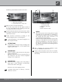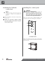
1
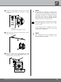
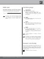
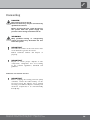
Operati ng Manual UK Water / Water Professional Heat pumps WWP series We reserve the right to modify technical specifications without prior notice. 83050800aUK – Translation of the operating manual © Alpha-InnoTec GmbH Please read first Symbols This operating manual provides important information on handling the unit. It is an integral part of the product and must be kept ready to hand in the immediate vicinity of the unit. It must remain available throughout the entire useful life of the unit. It must be handed over to subsequent owners or users of the unit. The following symbols are used in the operating manual. They have the following meaning: Information personnel. Read the operating manual before starting any work on or with the unit. Especially the chapter on safety. Follow all instructions in full and unreservedly. This operating manual may contain descriptions, which seem incomprehensible or unclear. If you have any questions or anything is still unclear, contact the factory's customer service department or the manufacturer's local partner. As this operating manual has been written for several types of unit, always keep to the parameters that apply to the respective type of unit. This operating manual is intended only for persons assigned to work on or with the unit. Treat all its constituent parts confidentially. They are protected by copyright. They may not be reproduced, transmitted, copied, stored in electronic systems or translated into another language, either wholly or in part, without the express written permission of the manufacturer. Information for users. or instructions for qualified Danger! Indicates imminent danger, which results in severe injuries or death. Warning! Indicates a potentially dangerous situation, which could result in severe injuries or death. Caution! Indicates a potentially dangerous situation, which could result in moderate or slight injuries. Important Indicates a potentially dangerous situation, which could result in property damage. Note. Emphasised information. € Energy saving tip Indicates advice, which helps to save energy, raw materials and costs. Reference to other sections of the operating manual. Reference to manufacturer. 2 other documents of the We reserve the right to modify technical specifications without prior notice. 83050800aUK – Translation of the operating manual © Alpha-InnoTec GmbH Contents Information for users and qualified personnel Please read first.. .................................................................2 Symbols......................................................................................2 Intended use...........................................................................4 Disclaimer................................................................................4 EC conformity......................................................................4 Safety..........................................................................................4 Customer service.................................................................5 Warranty / Guarantee.....................................................5 Disposal.....................................................................................5 Information for users How heat pumps work.....................................................5 Area of use and heat source requirements.......6 Heat metering........................................................................7 Operation.................................................................................7 Care of the unit.. .................................................................7 Maintenance of the unit...............................................7 Cleaning and flushing unit components.. ............................7 Technical data / Scope of delivery WWP 550X – WWP 1100X..............................................22 Performance curves Heating capacity/COP / Power consumption / Heat pump pressure loss WWP 550X..........................................................................24 WWP 700X..........................................................................25 WWP 900X..........................................................................26 WWP 1100X.........................................................................27 Dimensioned drawings..................................................28 Installation plans...........................................................29 Terminal diagram..............................................................31 Circuit diagrams WWP 550X..........................................................................32 WWP 700X – WWP 1100X..............................................35 Appendix EC Declaration of Conformity...............................38 General checklist............................................................39 Completion report for heat pump systems.......41 Customer service Service addresses.................................................................42 Malfunctions........................................................................8 Instructions for qualified personnel Scope of delivery. . .....................................................8 Installation...........................................................................9 Installation room....................................................................9 Transport to installation location.......................................9 Installation.............................................................................10 Installing the hydraulic connections............ 11 Electrical connection work..................................12 Flushing and filling the system..............................14 Flushing and filling the heating circuit..............................14 Water quality........................................................................14 Cleaning and flushing unit components.. ..........................15 Insulating the hydraulic connections...........16 Installing the control panel..................................16 Installation and removal of the screen..........18 Buffer tank...........................................................................19 Circulation pumps............................................................19 Domestic water heating.. .............................................19 Domestic hot water tank...........................................20 Commissioning....................................................................20 Dismantling..........................................................................21 We reserve the right to modify technical specifications without prior notice. 83050800aUK – Translation of the operating manual © Alpha-InnoTec GmbH 3 Intended use Safety The unit is only to be used for its intended purpose. This means: The unit is safe to operate for its intended use. The construction and design of the unit conform to current state of the art standards, all relevant DIN/VDE regulations and all relevant safety regulations. Every person who carries out work on the unit must have read and understood the operating manual before starting any work. This also applies if the person concerned has already worked with such a unit or a similar unit or has been trained by the manufacturer. Every person who carries out work on the unit must comply with the relevant local accident prevention and safety regulations. This especially applies to the wearing of personal protective clothing. • for heating. • for domestic water heating. The unit must be operated only within its technical parameters. “Technical data / scope of supply” overview. Note. Notify the responsible power supply company of the use of a heat pump or heat pump system. Disclaimer The manufacturer is not liable for any damage or losses resulting from use of the unit which is not its intended use. The manufacturer's liability also expires: •if work is carried out on the unit and its components contrary to the instructions in this operating manual. •if work is improperly carried out on the unit and its components. •if work is carried out on the unit which is not described in this operating manual, and this work has not been explicitly approved by the manufacturer in writing. •if the unit or components in the unit have been altered, modified or removed without the explicit written consent of the manufacturer. EC conformity The unit bears the CE marking. EC Declaration of Conformity 4 Warning! Risk of fatal electric shock! Electrical connection work must be carried out by qualified electricians only. Before opening the unit, safely disconnect the system from the power supply and prevent it from being switched back on! Warning! Only qualified personnel (trained heating, refrigerating system and refrigerant engineers and electricians) may carry out work on the unit and its components. Warning! Note and follow the safety stickers on and in the unit. Warning! Unit contains refrigerant! Leaking refrigerant could result in personal injury and environmental damage. Therefore: –Switch off system. –Thoroughly ventilate installation room. –Notify the manufacturer’s authorised service centre. Important For safety reasons: Never disconnect the unit from the power supply, unless the unit is being opened. We reserve the right to modify technical specifications without prior notice. 83050800aUK – Translation of the operating manual © Alpha-InnoTec GmbH Customer service How heat pumps work For technical information please contact your local heating engineer or the manufacturer's local partner. Heat pumps operate on the same principle as a refrigerator: same technology, only with reversed benefits. The refrigerator draws heat from food. which is released into the room through fins on the back. “Customer service” overview. Warranty / Guarantee For warranty and guarantee provisions, please refer to your purchase documents. The heat pump draws heat from our environment: air, earth or ground water. The extracted heat is conditioned in the unit and supplied to the heating water. Even when it is extremely cold outside, the heat pump draws enough heat to heat a house. Example: diagram of a brine/water heat pump with underfloor heating: Note. Please contact your dealer about all matters concerning warranties and guarantees. Disposal When withdrawing the old unit from service, always comply with the relevant local laws, guidelines, directives and standards concerning the recovery, recycling and disposal of the operating materials and components of chillers. “Dismantling”. We reserve the right to modify technical specifications without prior notice. 83050800aUK – Translation of the operating manual © Alpha-InnoTec GmbH 4 /4 =usable energy approx. 3 /4 =environmental energy approx. 1 ⁄4 =external electrical energy 5 Area of use and heat source requirements Important Taking into consideration the ambient conditions, limits of use and the relevant regulations, every heat pump can be used in new or existing heating systems. “Technical data / scope of delivery” overview, Note: Water temperature / water quantity The water in the extraction well of the heat source system must have a minimum temperature of 7 °C all year round and may not exceed a temperature of 25°C. Depending on the heat output required or its cooling capacity as a relevant variable for dimensioning the heat source, a minimum water rate is required, which must be provided by the heat source as a continuous output. Before installing the water/water heat pump, a pump test should/must be carried out for at least 12 hours with verification of a quasi-constantly lowered water table (persistence) in order to provide information about the quantity of water available. For efficient operation of the well, during the initial start-up the nominal flow rate must be adjusted on the heat source side. Any components required to enable flow balancing are to be installed in the pipe network here. The material of the components used must be chosen according to the water quality. The necessary flow rate (heat source water rate) must meet the heat pump's requirements. Evaluation of the water analysis Water constituents - minimum requirement. The water should be analysed in advance for the test values listed below (table). An important criterion to be used for taking water samples is the DVGW Standard, Technical Notices, Leaflet W 112 and use of the technical rules listed in it (DIN, EN and ISO standards). Designation Water quality 6 Water analyses are prepared by water test laboratories. Initial information about possible use of groundwater is available from your local water management authority. A pump test provides information as to whether a sufficient quantity / rate of water is available to cover the requirements for the heating output of your unit. The minimum groundwater flow rate must at least be available as a continuous output. “Technical data/Scope of delivery” overview, “Heat source flow rate” section. “Technical data/Scope of delivery” overview. In Germany the well must be designed and built to DIN 4021 and VDI 4640 (in other countries according to the corresponding regulations). Wells may only be drilled and built by drilling companies with a permit in accordance with DVGW W120. The water quality of the heat source is defined as normal groundwater. Ensure that the suction and return pipe always extends below the water level by sufficient depth, to ensure that oxygen is not added to the water (risk of iron oxide deposits). Please discuss the problem of iron oxide deposits with your well builder. During the planning the quality of the groundwater should be checked in advance as well as possible (e.g. by asking the competent water authority or searching for data on existing adjacent wells) and subsequently verified by water analysis in the built production well. The following table helps to assess the water quality. A water analysis and pump test must be carried out before installing the water/water heat pump. Limit pH value > 6.8 Iron level < 0.2 mg / l Manganese level < 0.1 mg / l Chloride level < 300 mg / l Level of free chlorine Turbidity Technical freedom from sand < 3 mg / l none < 0.1 mg / l sand per 10 l pumped water Important If a value does not conform to the value listed in the table, a water/water heat pump may not be used. Direct operation of the unit in conjunction with surface water, wastewater, industrial wastewater or mixtures of water and alkali solutions, acids or chlorine is also not allowed. We reserve the right to modify technical specifications without prior notice. 83050800aUK – Translation of the operating manual © Alpha-InnoTec GmbH Heat metering Care of the unit In addition to proof of the system's efficiency, the EEWaermeG (German law on renewable energy heat) also requires heat metering (referred to in the following as WME). The WME is mandatory for air/water heat pumps. For brine/ water and water/water heat pumps, a WME must be installed for flow temperatures ≥ 35 °C. The WME must record the total thermal energy output (heating and domestic hot water) in the building. In the case of heat pumps with heat metering the analysis is carried out via the controller. This displays the thermal energy output into the heating system in kWh. You can clean the outer surfaces of the unit with a damp cloth and proprietary household cleaning products. Do not use cleaning or care products that contain abrasives, acids and/or chlorine. Such products would irreparably damage the surfaces and could also cause technical damage to the unit. Operation By deciding to purchase a heat pump or a heat pump system you are making a long-term contribution to protecting the environment through low emissions and reduced primary energy use. You can operate and control the heat pump system with the control panel of the heating and heat pump controller. Note. Make sure that the control settings are correct. Operating manual of the heating and heat pump controller. To ensure that your heat pump or heat pump system operates efficiently and in an environmentally friendly way in heating mode, please pay particular attention to the following: € Energy saving tip Avoid unnecessarily high flow temperatures. The lower the flow temperature on the heating water side the more efficient the system. € Energy saving tip Preferably use purge ventilation. Compared to continuously open windows, this form of ventilation (fully opening windows for a short period, two to three times a day) reduces energy consumption and your heating bill. We reserve the right to modify technical specifications without prior notice. 83050800aUK – Translation of the operating manual © Alpha-InnoTec GmbH Maintenance of the unit The refrigerating circuit of the heat pump does not require any regular maintenance. According to EU Regulation (EC) 842/2006 of 17.05.2006, it is necessary to carry out leak inspections and to keep a log book for certain heat pumps! The criteria for whether or not it is necessary to perform a leak test and keep a log book are the hermetic impermeability of the refrigerating circuit and the refrigerant capacity of the heat pump! A log book is not required for heat pumps with a refrigerant capacity of < 3kg. For all other heat pumps, the log book is supplied with them. Log book for heat pumps, “Information on using the log book” section. The components of the heating circuit and the heat source (valves, expansion vessels, circulation pumps, filters, dirt traps) should be tested and cleaned as needed, however, at least annually, by qualified personnel (heating or refrigerating system fitters). It is best to arrange a maintenance agreement with a heating installation company. The company will arrange the necessary regular maintenance work. Cleaning and flushing unit components Caution! Unit components may be cleaned and flushed only by customer service personnel authorised by the manufacturer. Only use liquids recommended by the manufacturer. After flushing the condenser with chemical cleaning agent, any residues must be neutralised and the system thoroughly flushed with water. Always note and follow the technical data of the respective heat exchanger manufacturer. 7 Malfunctions Scope of delivery In the event of a malfunction, you can detect the cause of the malfunction via the diagnostics program of the heating and heat pump controller. Example layout of the scope of delivery: Operating manual of the heating and heat pump controller. Warning! Only customer service personnel authorised by the manufacturer may carry out service and repair work on the unit's components. “Customer service” overview. 1Compact unit with hermetic compressor, all safety-relevant components for refrigeration circuit monitoring, installed heating and heat pump controller, sensors installed in the unit for recording the heat source temperature as well as the hot gas, heater water flow and return temperature 2Separate package with: External temperature sensor, control panel of the heating and heat pump controller, screws (for the cover plates on the base) 3 Grit trap (on the pallet at the rear of the unit) Complete the following first: Check the delivery for outwardly visible signs of damage… Check to make sure that the delivery is complete… Any defects or incorrect deliveries must be reported immediately. Note. Note the unit model. “Technical data / scope of delivery” overview. 8 We reserve the right to modify technical specifications without prior notice. 83050800aUK – Translation of the operating manual © Alpha-InnoTec GmbH Installation Note. The following applies to all work to be done: Note. Always comply with the relevant local accident prevention regulations, statutory regulations, guidelines and directives. If several heat pumps of the same type are installed, only one heat pump must be considered. If several heat pumps of different types are installed, the heat pump with the largest refrigerant contents must be considered. Transport to installation location Warning! Only qualified personnel may install and assemble the heat pump or heat pump system! Always comply with the following safety information during transport: Note. Note the sound information for the respective model. “Technical data / Scope of delivery” overview, “Sound” section. Caution! Wear safety gloves. Warning! Several people are required to transport the unit. Take into account the weight of the unit. “Technical data / Scope of delivery” overview, “General unit data” section, Installation room Warning! Important Install the heat pump inside buildings only. The installation room must be frost-free and dry. –Take suitable precautions to prevent the risk of tipping over. Warning! Please note and follow the respective relevant local standards, guidelines, directives and regulations, especially the minimum room volume necessary depending on the quantity of refrigerant in the relevant heat pump system (EN 378-1). Refrigerant R 134a R 404A R 407C R 410A The unit can tilt and tip over when being removed from the wooden pallet and during transport. This can result in personal injury and damage to the unit. Limit 0.25 kg/m³ 0.48 kg/m³ 0.31 kg/m³ 0.44 kg/m³ “Technical data / scope of supply” overview, “General unit data” section. Minimum room volume = Caution! Always secure the unit against slipping during transport. Important Never use components and hydraulic connections on the unit for transport purposes. Important Do not damage the hydraulic connections under any circumstances. Refrigerant capacity [kg] Limit [kg/m³] We reserve the right to modify technical specifications without prior notice. 83050800aUK – Translation of the operating manual © Alpha-InnoTec GmbH 9 Important Do not tilt the unit more than a maximum of 45° in any direction. Note. To prevent transport damage, you should transport the unit to its final place of installation in its packed condition (on the wooden pallet with packaging) using a pallet truck. Remove packaging and set extra box aside (will be needed later on!)... Move the pallet truck under the unit… Always refer to and follow the installation plan for the respective model. Note the size and minimum clearances. Installation plan for the respective model. Important The heat pump must be installed on a firm, horizontal floor. Ensure that the floor is designed for the weight of the heat pump. Do not use a rigid foam boiler pedestal “Technical data/Scope of delivery” overview, “General unit data” section. Note. Install the unit so that the operator side is accessible at all times! Important Note. The two openings for the pallet truck must be closed off using the cover plates supplied (two screws each). Do not tilt the unit more than a maximum of 45° in any direction. Note. Note. Please always close off the transport openings to reduce noise! The openings for the pallet truck must be closed off using the cover plates supplied! Detailed drawing of concrete foundation: Installation Caution! Several people are required to install the unit. Note. Take into account the size of the unit. “Technical data / Scope of delivery” overview, “General unit data” section. 10 1Screed 2 approx. 100 mm 3Structural borne sound insulation depending on weight of heat pump 4Concrete foundation 5Perimeter insulation strips 6 Impact sound insulation 7Concrete ceiling We reserve the right to modify technical specifications without prior notice. 83050800aUK – Translation of the operating manual © Alpha-InnoTec GmbH Installing the hydraulic connections Important Danger! Risk of fatal electric shock! Before opening the unit, safely disconnect the system from the power supply and prevent it from being switched back on! When installing the connections, always secure the connections on the unit against twisting, in order to prevent damage to the copper pipes inside the unit. Proceed as follows: Install shut-off devices in the heating circuit… Install shut-off devices at the heat source… Important Connect the unit to the heating circuit according to the hydraulic diagram for the respective model. Note. By installing the shut-off devices, the evaporator and condenser of the heat pump can be flushed, if necessary. “Hydraulic connection” instructions. Caution! Important The heat source system must be designed according to the specifications of the planning manual. Planning manual and “Hydraulic connection” documents. Note: The condenser may only be flushed by customer service personnel authorised by the manufacturer. Position a bleeder (vent) at the highest point of the heat source in the heat source outlet… You must make the connection to the fixed piping via flanged expansion joints (accessories available separately for an additional charge): Check to make sure that the cross-sections and lengths of the pipes for the heating circuit and the heat source are adequately dimensioned. The flanged expansion joints provide vibration isolation. Note: Circulation pumps must be designed as constant speed pumps. They must at least produce the minimum throughput required for your unit model. “Technical data / Scope of delivery” overview, “Heating circuit” and “Heat source” sections. Important The hydraulics must be equipped with a buffer tank, the volume of which depends on your unit model. The hydraulic connections are located at the rear of the unit. Always install the dirt filter included with the unit at the heat source inlet (return) connection… The heating water and heat source connections are marked on the unit accordingly. For the position of the connections, please refer to the dimensioned drawing for the respective model. Dimensioned drawings We reserve the right to modify technical specifications without prior notice. 83050800aUK – Translation of the operating manual © Alpha-InnoTec GmbH 11 Screw the expansion joints onto the unit's connections until they lie against the rubber sealing collar… Screw the expansion joints onto the fixed piping of the heat source by hand until they lie against the rubber sealing collar… Electrical connection work The following applies to all work to be done: Danger! Risk of fatal electric shock! Electrical connection work must be carried out by qualified electricians only. Before opening the unit, safely disconnect the system from the power supply and prevent it from being switched back on! Warning! Retighten all connections by one to two turns of the thread using a suitable tool (e.g. a pipe wrench), to make them tight… Do not over tighten. The rubber of the expansion joints must not twist (torsion). Otherwise malfunctions through to serious damage to the unit can occur. During installation and when carrying out electrical work, comply with the relevant EN‑, VDE and/or local safety regulations. Comply with technical connection requirements of the responsible power supply company (if required by the latter)! Note. All live cables must be stripped before they are laid in the cable duct of the switchbox! Remove front panel of the unit... Open the quick-release screws of the front panel by turning them 90° anticlockwise… Lift out the front panel and set aside in a safe place 12 We reserve the right to modify technical specifications without prior notice. 83050800aUK – Translation of the operating manual © Alpha-InnoTec GmbH Familiarise yourself with the inside of the unit… 1 Electrical switchbox 2 Intermediate floor of the unit 1Compressor power connection 3~PE 2Control connection 3N/PE 4Phase sequence relay Open the unit's electrical switchbox… To do this, only loosen the two upper screws of the cover panel. Remove the remaining screws. The cover plate can then be removed… Lay the load and external control and sensor cables through the cable duct to the terminals. Tighten the strain relief screws… Note. Install electrical connections according to the terminal diagram and the circuit diagrams. “Terminal diagrams” and “Circuit diagrams” for the respective model. Attention! Install electric connections only according to the terminal diagram and the circuit diagrams that apply to your model. Important Ensure clockwise rotary field of the load power supply (compressor). –Operation with the incorrect rotary direction of the compressor can cause serious, irreparable damage to the compressor. The control panel of the heating and heat pump controller can be connected to a computer or network using a suitable network cable, enabling the heating and heat pump controller to be controlled remotely from there. If this is required, install a shielded network cable (category 6, with RJ‑45 connector) through the unit when installing the connections and run it through the front panel of the unit, parallel to the existing control cable of the heating and heat pump controller. After completing all electrical installation work, close the switchbox inside the unit… Screw on the front panel of the unit, if no further installation work inside the unit is to be carried out immediately. Important Ensure the power supply of the heat pump is fitted with a 3-pole miniature circuit-breaker with at least 3mm contact gap. Note the level of the tripping current. “Technical data / Scope of delivery” overview, “Electrics” section. We reserve the right to modify technical specifications without prior notice. 83050800aUK – Translation of the operating manual © Alpha-InnoTec GmbH 13 Flushing and filling the system Important The system must be absolutely free from air before commissioning. Principles of Part I and Part II The occurrence of scaling and corrosion damage in hot water heating systems is low, if - p roper planning, design and commissioning is carried out - the system is closed in corrosion terms - adequately dimensioned pressurising is integrated Flushing and filling the heating circuit - the guide values for the heating water are complied with - and regular servicing and maintenance are carried out. Water quality of the fill and top-up water in water heating systems according to VDI 2035 Part I and II Use of modern, energy-efficient heat pump systems is becoming increasingly widespread. Their ingenious technology enables these systems to achieve very good efficiencies. The decreasing space available for heat generators has led to the development of compact units with increasingly smaller cross-sections and high heat transfer capacities. This means that the complexity of the systems and the material diversity are also increasing, which plays an important role, especially in their corrosion behaviour. Alpha InnoTec ensures continuous technological advances, but all these technical refinements require the system to be operated with correctly filled heating water. The heating water not only affects the efficiency of the system, but also the life of the heat generator and the heating components of a system. The guide values of VDI 2035 Part I and Part II must therefore be complied with as minimum requirements for proper operation of the systems. Our practical experience has shown that the safest, most reliable and fault-free running is achieved with so-called low-salt operation. VDI 2035 Part I provides important information and recommendations regarding scaling and its prevention in heating and domestic hot water heating systems. VDI 2035 Part II primarily deals with the requirements for reducing heating water corrosion in hot water heating systems. A system log should be kept, in which the relevant planning & design data is entered (VDI 2035). Damage that can occur in case of failure to comply with the above - Malfunctions and the failure of components (e.g. pumps, valves) - Internal and external leaks (e.g. from heat exchangers) - Cross-section reduction and blocking of components (e.g. heat exchanger, pipes, pumps) - Material fatigue - Gas bubbles and gas cushion formation (cavitation) - Negative effect on heat transfer (formation of coatings, deposits) and associated noises (e.g. boiling noises, flow noises) Limescale – the energy killer Filling with untreated drinking water inevitably leads to the precipitation of all calcium as scale. The consequence: limescale deposits form on the heat transfer surfaces of the heating. The efficiency falls and the energy costs rise. A rule of thumb is that 1 millimetre of limescale deposit causes an efficiency loss of 10%. In extreme cases it can even cause damage to the heat exchangers. Water softening to VDI 2035 – Part I If the water is softened in accordance with the VDI 2035 guidelines before it is used to fill the heating system, no scale can form. This effectively and permanently prevents limescale deposits and the resulting negative effects on the entire heating system. 14 We reserve the right to modify technical specifications without prior notice. 83050800aUK – Translation of the operating manual © Alpha-InnoTec GmbH Corrosion – an underestimated problem Monitoring VDI 2035, Part II, deals with the problem of corrosion. Softening the heating water can prove to be insufficient. The pH value can significantly exceed the limit of 10. pH values higher than 11 can set in, which even damage rubber seals. The VDI 2035, Part 1 guidelines are fulfilled; however, VDI 2035, Part 2 suggests a pH value between 8.2 and maximum 10. Analytical recording and monitoring of the relevant water values and the added conditioning substances is of decisive importance. Therefore, they should be monitored regularly using appropriate water test equipment. If aluminium materials are used, which is the case in many modern heating systems, a pH value of 8.5 must not be exceeded! Because otherwise there is a threat of corrosion – aluminium is attacked without the presence of oxygen. Therefore, apart from softening the heating fill and make-up water, the heating water should also be appropriately conditioned. This is the only way to comply with the VDI 2035 requirements and the recommendations and installation instructions of the heat pump manufacturer. Before flushing and filling the heating circuit, the drain pipe of the safety assembly must be connected. Part 2 of VDI 2035 also refers to the reduction in total salt content (conductivity). The risk of corrosion is far lower if deionised water is used than is the case if the system is operated with salty, i.e. softened water. Even if drinking water has been softened beforehand, it contains dissolved, corrosive salts, which act as electrolytes due to the use of different materials in the heating system and thus accelerate corrosion processes. This can ultimately result in pitting. On the safe side with low-salt operation The problems listed above do not occur at all with lowsalt operation, as the heating water contains neither corrosive salts such as sulphates, chlorides and nitrates nor alkalising sodium hydrogen carbonate. The corrosive properties of deionised water are very low and in addition, scale cannot form in the boiler. This is the ideal approach for closed heating circuits, in particular, because low oxygen input into the heating circuit can also be tolerated. Important Flush the heating circuit thoroughly… Note. Flush heat pump and heating circuit for about 5 minutes. Fill the heating circuit… Bleed (vent) the heating circuit. Cleaning and flushing unit components Caution! Unit components may be cleaned and flushed only by customer service personnel authorised by the manufacturer. Only use liquids recommended by the manufacturer. After flushing the condenser with chemical cleaning agent, any residues must be neutralised and the system thoroughly flushed with water. Always note and follow the technical data of the respective heat exchanger manufacturer. In general, when the system is filled with deionised water, the pH value sets itself within the ideal range due to internal alkalinisation. If necessary, a pH value of 8.2 can be very easily alkalised by adding chemicals. In this way, optimum protection of the entire heating system is achieved. We reserve the right to modify technical specifications without prior notice. 83050800aUK – Translation of the operating manual © Alpha-InnoTec GmbH 15 Insulating the hydraulic connections Note. Insulate the heating circuit and the heat source according to relevant local standards and guidelines. Check all hydraulic connections for leaks. Perform pressure test… Installing the control panel Danger! Risk of fatal electric shock! Electrical connection work must be carried out by qualified electricians only. Before opening the unit, safely disconnect the system from the power supply and prevent it from being switched back on! There are 4 each recesses at different heights in the front panel of the unit for fastening the control panel: Insulate all connections, vibration isolators, connections and pipes of the heating circuit and the heat source. Insulate the heat source so that it is vapour-diffusion tight. 1 four upper recesses 2 four lower recesses There are 4 hooks at the rear of the control panel, which are used to hook the control panel on the front panel of the unit: 16 We reserve the right to modify technical specifications without prior notice. 83050800aUK – Translation of the operating manual © Alpha-InnoTec GmbH Hook the control panel's hooks into the recesses of the front panel (either in the upper or lower recesses)... Note. A connection to a computer or a network can be made via the left socket at the bottom of the control panel, thereby allowing the heating and heat pump controller to be controlled remotely from there. This requires a shielded network cable (category 6) to be laid through the unit during the electrical connection work. Operating manual for the heating and heat pump controller, “Qualified technician” version, “Web server” section. Example: Control panel in upper recesses Push down the hooked in control panel, until it latches into place… If this network cable is available, insert the network cable's RJ‑45 connector into the left socket of the control panel. Note. The network cable can be exchanged at any time. In order to be able to connect it, the screen must first be removed. Push the control cable of the heating and heat pump controller into the right-hand socket on the underside of the control panel… We reserve the right to modify technical specifications without prior notice. 83050800aUK – Translation of the operating manual © Alpha-InnoTec GmbH 17 Installation and removal of the screen Installing the screen Note. The masking plate is provided in the as delivered unit so that the control panel is inserted in the upper recesses of the front panel. If the control panel has been inserted in the lower recesses of the front panel, you must first remove the masking plate's dummy cover and then reinsert it above the logo. Then, on the opposite side, latch the lugs on the masking plate from the bottom up into the slots provided in the front panel… Finally, press the upper latching lugs of the masking plate into the slots provided in the front panel. Screen at time of delivery: 1 Recess for control panel 2Logo 3Dummy cover First, insert the masking plate below in the slots provided in the front panel… Dismantling the masking plate In order to dismantle the masking plate, the latching lugs must be completely released on one side first by pushing towards the middle of the masking plate. Then release the lugs on the opposite side. Then, beginning on one side, latch the lugs on the masking plate from the bottom up into the slots provided in the front panel… 18 We reserve the right to modify technical specifications without prior notice. 83050800aUK – Translation of the operating manual © Alpha-InnoTec GmbH Buffer tank Circulation pumps The hydraulic integration of the heat pump requires a buffer tank in the heating circuit. The necessary volume of the buffer tank is given by the following formula: VBuffer tank = minimum throughput heating circuit flow rate / hour 10 For details of the minimum throughput heating circuit flow rate, refer to the “Technical data/ Scope of delivery” overview, “Heating circuit” section. Important Always note the unit model. Do not use controlled circulation pumps. Heating circuit and domestic hot water circulation pumps must be designed as constant speed pumps. Note: The minimum heating water, heat source flow rate must be ensured! Note: When dimensioning the circulation pump of the heat sources the viscosity of the brine liquid must be taken into account! Note: A motor protection switch for the pump is integrated in the heat pump! An external motor protection switch must be installed if a stronger groundwater pump is required. “Technical data/Scope of delivery” overview, Electrics. For details of the minimum heating circuit/heat source flow rate, refer to the “Technical data/ Scope of delivery overview, “Heating circuit” “heat source” section for the respective type. Domestic water heating Domestic water heating with the heat pump requires an additional heating water circuit (parallel) to the heating circuit. When connecting, make sure that the domestic hot water charge is not fed through the buffer tank of the heating circuit. “Hydraulic connection” documents. We reserve the right to modify technical specifications without prior notice. 83050800aUK – Translation of the operating manual © Alpha-InnoTec GmbH 19 Domestic hot water tank If the heat pump is to be used for domestic water heating, you must integrate special domestic hot water tanks in the heat pump system. Choose a storage volume so that the required quantity of domestic hot water is available even during a power failure. Commissioning Carry out a thorough installation check and work through the items on the general checklist… “General checklist”. The installation check will prevent damage to the heat pump system that can be caused by incorrectly carried out work. Ensure that… Note: The heat exchanger surface of the domestic hot water tank must be dimensioned so that the heating output of the heat pump is transferred with minimum spread. You can choose a domestic hot water tank from our product range. They are optimally matched to your heat pump. •the load power supply (compressor) has a clockwise rotary field. •the heat pump is installed and assembled according to the requirements in this operating manual. •the electrical installation work has been carried Note: Integrate the domestic hot water tank in the heat pump system as shown in the hydraulic diagram for your system. Note: A motor protection switch for the heat source circulation pump is integrated in the heat pump! An external motor protection switch must be installed if a stronger groundwater pump is required. “Technical/Scope of delivery” setting range out properly. •a 3-pole fuse has been installed for the compressor. It must have a contact opening gap of at least 3 mm. A 3 pole miniature circuit breaker must be installed. • the heating circuit and the heat source are flushed, filled and bled thoroughly. • all valves and shut-off devices of the heating circuit are open. •all valves and shut-off devices of the heat source are open. •all pipe systems and components of the system are leaktight. Carefully fill out and sign the completion report for heat pump systems… “Completion report for heat pump systems”. In Germany: Send completion report for heat pump systems and general checklist to the manufacturer’s factory customer service department. Outside of Germany: Send completion report for heat pump systems and general checklist to the manufacturer’s local partner. “Customer service” overview. The heat pump system will be commissioned by customer service personnel authorized by the manufacturer. There is a fee for commissioning! 20 We reserve the right to modify technical specifications without prior notice. 83050800aUK – Translation of the operating manual © Alpha-InnoTec GmbH Dismantling Danger! Risk of fatal electric shock! Electrical work may only be carried out by qualified electricians. Before opening the unit, safely disconnect the system from the power supply and prevent it from being switched back on! Warning! Only qualified heating or refrigerating system personnel may dismantle the unit from the system. Important The antifreeze mixture of the heat source must not be allowed to get into the sewers. Collect antifreeze mixture and dispose of properly. Important Recycle or ensure proper disposal of unit components, refrigerants and oil according to the relevant regulations, standards and guidelines. Removing the buffer battery Important Before scrapping the heating and heat pump controller, remove the buffer battery on the processor board. The battery can be pushed out using a screwdriver. Dispose of battery and electronic components in an environmentally friendly way. We reserve the right to modify technical specifications without prior notice. 83050800aUK – Translation of the operating manual © Alpha-InnoTec GmbH 21 Technical data / Scope of delivery Heat pump type Brine/water ı Air/water ı Water/water • applicable ı — not applicable Installation location Indoors ı Outdoors • applicable ı — not applicable Conformity Performance data Limits of use CE Heating capacity/COP at W10/W35 Standard point to EN255 2 compressors 1 compressor kW ı … kW ı … W10/W50 Standard point to EN255 2 compressors 1 compressor kW ı … kW ı … W7/W35 Standard point to EN255 2 compressors 1 compressor kW ı … kW ı … W10/W45 Standard point to EN14511 2 compressors 1 compressor kW ı … kW ı … Heating circuit °C Heat source °C additional operating points Sound … Sound pressure level averaged at distance of 1m around the machine (in free field) dB(A) Sound power level to EN12102 Heat source dB Flow rate: minimum flow ı nominal flow ı maximum flow l/h Heat pump pressure loss ∆p ı Flow rate bar ı l/h Recommended heat source pump … Total compression of the recommended pump at nominal heat source flow rate Grit trap bar ı l/h taken into account in WP pressure loss: • yes Dirt trap pressure loss ∆p ı Flow rate Heating circuit bar ı l/h Flow rate: minimum flow ı nominal flow ı maximum flow l/h Heat pump pressure loss ∆p ı Flow rate bar ı l/h Free compression heat pump ∆p ı Flow rate bar ı l/h Temperature spread for W10/W35 General unit data K Dimensions (see dimensioned drawing for the specified unit size) unit size Total weight kg (kg) Additional weight module 1 kg Additional weight module 2 kg Connections Heating circuit … Heat source … Refrigerant Refrigerant type ı Quantity Electrics … ı kg Voltage code ı all-pole circuit breaker heat pump *) …ı A Voltage code ı circuit breaker control voltage *) …ı A Voltage code ı circuit breaker electric heating element *) Heat pump ı A Effective power consumption in the standard point W10/W35 to EN255: Power consumption ı current consumption ı cosφ kW ı A ı … Maximum machine current within the use limits A Starting current: direct ı with soft starter A ı A Degree of protection Output, electric heating element 3 ı 2 Components IP ı 1 phase kW ı kW ı kW Circulation pump, heating circuit at nominal flow rate: Power consumption ı current consumption kW ı A Circulation pump, heat source at nominal flow rate: Power consumption ı current consumption kW ı A Setting range of heat source pump motor protection switch A Passive cooling function Specification only for units with designator K: Cooling output at nominal flow rate (15°C heat source, 25°C heating water) Safety equipment Safety assembly heating circuit ı Safety assembly heat source Heating and heat pump controller kW Included in scope of delivery: • yes — no Included in scope of delivery: • yes — no Electronic soft starter Expansion vessels integrated: • yes DE813240-a 22 — no Heat source: Scope of delivery ı Volume ı Initial pressure • yes — no ı l ı bar Heating circuit: Scope of delivery ı Volume ı Initial pressure • yes — no ı l ı bar Overflow valve Vibration decouplers — no integrated: • yes Heating circuit ı heat source — no Included in scope of delivery: • yes — no *) comply with local regulations n.d. = not detectable We reserve the right to modify technical specifications without prior notice. 83050800aUK – Translation of the operating manual © Alpha-InnoTec GmbH WWP 550X WWP 700X WWP 900X WWP 1100X —ı—ı• —ı—ı• —ı—ı• —ı—ı• •ı— •ı— •ı— •ı— • • • • 53,4 ı 5,3 28,3 ı 5,4 72,0 ı 5,4 38,2 ı 5,5 88,9 ı 5,2 47,1 ı 5,4 107,6 ı 5,3 57,0 ı 5,4 52,3 ı 3,8 27,7 ı 3,9 70,6 ı 3,9 37,4 ı 4,0 87,2 ı 3,7 46,2 ı 3,8 105,5 ı 3,8 55,9 ı 3,9 50,0 ı 5,0 26,5 ı 5,1 67,7 ı 5,1 35,9 ı 5,2 83,6 ı 4,9 44,3 ı 5,1 101,2 ı 5,0 53,6 ı 5,1 49,7 ı 4,0 26,3 ı 4,0 66,7 ı 4,0 35,5 ı 4,1 82,7 ı 4,0 43,8 ı 4,0 100,0 ı 4,0 53,0 ı 4,0 20 - 60 20 - 60 20 - 60 20 - 60 7 - 25 7 - 25 7 - 25 7 - 25 — — — — 55 55 57 57 — — — — 10600 ı 10600 ı 18600 14400 ı 14400 ı 25000 17600 ı 17600 ı 30600 21400 ı 21400 ı 37400 0,23 ı 10600 0,21 ı 14400 0,26 ı 17600 0,20 ı 21400 Grundfos SP8A-5 Grundfos SP17-3 Grundfos SP17-3 Grundfos SP30-3 1,40 ı 10600 2,7 ı 14400 2,31 ı 17600 2,74 ı 21400 • • • • —ı— —ı— —ı— —ı— 4600 ı 5000 ı 11400 6100 ı 6600 ı 12800 7600 ı 8500 ı 15500 9200 ı 10100 ı 18500 0,06 ı 5000 0,06 ı 6600 0,06 ı 8500 0,08 ı 10100 —ı— —ı— —ı— —ı— 9,1 9,3 8,9 9,1 1 1 1 1 560 570 580 610 — — — — — — — — DN50 DIN 2566 DN50 DIN 2566 DN50 DIN 2566 DN50 DIN 2566 DN50 DIN 2566 DN50 DIN 2566 DN50 DIN 2566 DN50 DIN 2566 R407c ı 8,0 R407c ı 10,7 R407c ı 13,0 R407c ı 15,80 3~/PE/400V/50Hz ı C40 3~/PE/400V/50Hz ı C50 3~/PE/400V/50Hz ı C63 3~/PE/400V/50Hz ı C80 1~/N/PE/230V/50Hz ı B10 1~/N/PE/230V/50Hz ı B10 1~/N/PE/230V/50Hz ı B10 1~/N/PE/230V/50Hz ı B10 —ı— —ı— —ı— —ı— 10,1 ı 2x 10,3 ı 0,71 13,3 ı 2x 12,2 ı 0,79 17,1 ı 2x 16,0 ı 0,77 20,3 ı 2x 18,2 ı 0,81 2x 14,9 2x 19,8 2x 24,3 2x 25,13 98 ı 41 120 ı 85 150 ı 90 198 ı 125 20 20 20 20 —ı—ı— —ı—ı— —ı—ı— —ı—ı— —ı— —ı— —ı— —ı— 0,75 ı 2,3 2,2 ı 5,5 2,2 ı 5,5 3,0 ı 7,85 1,8 - 2,5 5,5 - 8,0 5,5 - 8,0 5,5 - 8,0 — — — — —ı— —ı— —ı— —ı— • • • • • • • • —ı— —ı— —ı— —ı— —ı— —ı— —ı— —ı— — — — — — — — — 813226-a 813220-f 813221-f 813222-f We reserve the right to modify technical specifications without prior notice. 83050800aUK – Translation of the operating manual © Alpha-InnoTec GmbH 23 WWP 550X Performance curves Qh (kW) COP 80 8 7 6 70 5 4 3 60 2 5 10 15 20 25 30 Temp„ (°C) 50 Pe (kW) 20 40 15 30 10 35°C 2VD 50°C 2VD 5 35°C 1VD 50°C 1VD 20 0 5 10 15 20 25 30 5 10 15 20 25 30 Temp„ (°C) Temp„ (°C) ∆p (bar) ∆p (bar) 0,8 0,4 0,7 0,6 0,3 0,5 0,4 0,2 0,3 0,2 0,1 0,1 0,0 0,0 0,0 2,0 4,0 6,0 8,0 0,0 10,0 5,0 “” 10,0 15,0 20,0 “„ Δp” Δp„ 823213 Legende: DE823208L “” Volumenstrom Heizwasser “„ Volumenstrom Wärmequelle Temp„ Legend: Temperatur Wärmequelle UK823200 Qh “” Heizleistung Heating water flow rate “„ Heat source flow rate Temp„ Heat source temperature Qh Heating capacity Druckverlust Wärmequelle Pe COP ∆p” ∆p„ Pe Leistungsaufnahme Coefficient of performance / Leistungszahl Druckverlust Heizkreis Power consumption COP Coefficient of performance / efficiency rating ∆p” Free compression, heating circuit ∆p„ Heat source pressure loss VD Änd./Ä.M./Ersteller/Datum Compressor - / PEP007-2009 / Neumann / 25.02.09 Bezeichnung: Seite: 1/1 Leistungs-Druckverlustkurven WWP550X Zeichnungsnummer: 823213 Datei: 823213 Leistungs-Druckverlustkurven WWP550X 24 We reserve the right to modify technical specifications without prior notice. 83050800aUK – Translation of the operating manual © Alpha-InnoTec GmbH Performance curves WWP 700X Qh (kW) COP 100 8 7 6 90 5 4 3 80 2 5 10 15 20 25 30 70 Temp„ (°C) 60 Pe (kW) 25 50 20 15 35°C 2VD 40 50°C 2VD 10 35°C 1VD 50°C 1VD 30 5 5 10 15 20 25 30 5 10 15 20 25 30 Temp„ (°C) Temp„ (°C) ∆p (bar) ∆p (bar) 0,8 0,4 0,7 0,6 0,3 0,5 0,4 0,2 0,3 0,2 0,1 0,1 0,0 0,0 0,0 2,0 4,0 6,0 8,0 10,0 12,0 0,0 14,0 5,0 “” 10,0 15,0 20,0 25,0 “„ Δp” Δp„ 823210 Legende: DE823025L “” “„ Volumenstrom Heizwasser Volumenstrom Wärmequelle Temp„ Legend: Temperatur Wärmequelle UK823200 Qh “” Heizleistung Heating water flow rate Pe Leistungsaufnahme “„ Heat source flow rate Temp„ Heat source temperature Qh Heating capacity Druckverlust Wärmequelle COP ∆p” ∆p„ Pe Coefficient of performance / Leistungszahl Druckverlust Heizkreis Power consumption COP Coefficient of performance / efficiency rating ∆p” Free compression, heating circuit ∆p„ Heat source pressure loss VD Änd./Ä.M./Ersteller/Datum Compressor - / ÄM001-2007 / Neumann / 14.02.08 Bezeichnung: Seite: 1/1 Leistungs-Druckverlustkurven WWP700X Zeichnungsnummer: 823210 Datei: 823210 Leistungs-Druckverlustkurven WWP700X We reserve the right to modify technical specifications without prior notice. 83050800aUK – Translation of the operating manual © Alpha-InnoTec GmbH 25 WWP 900X Performance curves Qh (kW) COP 130 8 7 120 6 5 110 4 3 100 2 5 90 10 15 20 25 30 Temp„ (°C) 80 Pe (kW) 70 30 60 25 20 50 35°C 2VD 15 50°C 2VD 40 35°C 1VD 10 50°C 1VD 30 5 5 10 15 20 25 30 5 10 15 20 25 30 Temp„ (°C) Temp„ (°C) ∆p (bar) ∆p (bar) 0,8 0,4 0,7 0,6 0,3 0,5 0,4 0,2 0,3 0,2 0,1 0,1 0,0 0,0 0,0 5,0 10,0 15,0 0,0 20,0 5,0 10,0 “” 15,0 20,0 25,0 30,0 35,0 “„ Δp” Δp„ 823211 Legende: DE823025L “” Volumenstrom Heizwasser “„ Volumenstrom Wärmequelle Temp„ Legend: Temperatur Wärmequelle UK823200 Qh “” Heizleistung Heating water flow rate “„ Heat source flow rate Temp„ Heat source temperature Qh Heating capacity Druckverlust Wärmequelle Pe COP ∆p” ∆p„ Pe Leistungsaufnahme Coefficient of performance / Leistungszahl Druckverlust Heizkreis Power consumption COP Coefficient of performance / efficiency rating ∆p” Free compression, heating circuit ∆p„ Heat source pressure loss VD Änd./Ä.M./Ersteller/Datum Compressor - / ÄM001-2007 / Neumann / 14.02.08 Bezeichnung: Seite: 1/1 Leistungs-Druckverlustkurven WWP900X Zeichnungsnummer: 823211 Datei: 823211 Leistungs-Druckverlustkurven WWP900X 26 We reserve the right to modify technical specifications without prior notice. 83050800aUK – Translation of the operating manual © Alpha-InnoTec GmbH Performance curves WWP 1100X Qh (kW) COP 150 8 7 140 6 5 130 4 120 3 2 110 5 10 15 20 25 30 100 Temp„ (°C) 90 Pe (kW) 80 30 25 70 20 60 35°C 2VD 15 50°C 2VD 50 35°C 1VD 10 50°C 1VD 40 5 5 10 15 20 25 30 5 10 15 20 25 30 Temp„ (°C) Temp„ (°C) ∆p (bar) ∆p (bar) 0,8 0,4 0,7 0,6 0,3 0,5 0,4 0,2 0,3 0,2 0,1 0,1 0,0 0,0 0,0 5,0 10,0 15,0 0,0 20,0 5,0 10,0 “” 15,0 20,0 25,0 30,0 35,0 40,0 “„ Δp” Δp„ 823212 Legende: DE823025L “” “„ Volumenstrom Heizwasser Volumenstrom Wärmequelle Temp„ Legend: Temperatur Wärmequelle UK823200 Qh “” Heizleistung Heating water flow rate Pe Leistungsaufnahme “„ Heat source flow rate Temp„ Heat source temperature Qh Heating capacity Druckverlust Wärmequelle COP ∆p” ∆p„ Pe Coefficient of performance / Leistungszahl Druckverlust Heizkreis Power consumption COP Coefficient of performance / efficiency rating ∆p” Free compression, heating circuit ∆p„ Heat source pressure loss VD Änd./Ä.M./Ersteller/Datum Compressor - / ÄM001-2007 / Neumann / 14.02.08 Bezeichnung: Seite: 1/1 Leistungs-Druckverlustkurven WWP1100X Zeichnungsnummer: 823212 Datei: 823212 Leistungs-Druckverlustkurven WWP1100X We reserve the right to modify technical specifications without prior notice. 83050800aUK – Translation of the operating manual © Alpha-InnoTec GmbH 27 WWP 550X – WWP 1100X $ ) Dimensioned drawings % ( ( ! ' & Legend: UK819224~d All dimensions in mm. % Item A B E Front view Side view from left Rear view 1 2 3 4 5 6 7 Designation Control panel Penetrations for electric/sensor cables Heating water outlet (flow) Heat source inlet Heat source outlet Heating water inlet (return) Strain relief devices Connection Flange Flange Flange Flange 2" 2" 2" 2" IG IG IG IG DIN DIN DIN DIN 2566 2566 2566 2566 $ 28 We reserve the right to modify technical specifications without prior notice. 83050800aUK – Translation of the operating manual © Alpha-InnoTec GmbH G F 1 2 3 4 Installation plan 1/2 5 WWP 550X – WWP 1100X A > 2000 1690 1 2 800 1000 1120 > 800 C > 800 1 Legend: UK819135~c All dimensions in mm. 1 Item A C Front view Top view 1 2 Designation Shaded area = free space for service purposes Concrete foundation with sound insulation inlay 2 3 We reserve the right to modify technical specifications without prior notice. 83050800aUK – Translation of the operating manual © Alpha-InnoTec GmbH 4 c ÄM 999/2007 12.4.2007 RA b ÄM 999/2006 1.2.2006 a 999/2005 15.1.2005 RA - PEP 021/2003 18.11.2004 RA Zust. Änderungstext Datum 29 Mar Vo WWP 550X – WWP 1100X E 1 2 3 Installation plan 2/2 4 C F D > 1600 800 > 800 E C Oberflächen 1:20 Maßstab Datum Name Aepfelbach 12.4.2007 Aepfelbach pha-InnoTec GmbH Industriestraße 3 - 95359 Kasendorf ww.alpha-innotec.de B 1:50 Det. Maßstab C Werkstoff SO 2768 -c t 4.6.2004 Schutzvermerk nach DIN 34 beachten lgemeinoleranz 2040 D 1 Gewicht 15076,762 kg Benennung Aufstellung_Mindestabstände_SWP_WWP 2 A 1000 Blatt ArtikelNr. 1 819136 Ers. f. von1 B 2 Ers. d. A 1 2 3 4 c ÄM 99 b ÄM 00 a 999/20 - PEP 0 Zust. Änder Legend: UK819136 All dimensions in mm. C Item 1 2 30 Top view Designation Shaded area = free space for service purposes Concrete foundation with sound insulation inlay We reserve the right to modify technical specifications without prior notice. 83050800aUK – Translation of the operating manual © Alpha-InnoTec GmbH WWP 550X – WWP 1100X 1 L2 L3 PE 2 -F12 3 PE N Änderung Datum 11.03.2008 3 BOSUP 5 A3 Name PE 6 -X7 N N PE PE PE 8 Ers. für Projekt: Ers. durch 11 MA1 ZW2/SST MZ1 12 Klemmenplan SWP / WWP ANr. 13 Kunde: TA 14 GND Version 0.0 TRL 10 GND -X4 TB1 A1 ZIP TB1 GND -X3 M ZIP MIS RFV RFV 9 BUP BUP ZW1 ZW2 ZW1 -X2 ZUP VBO -X0 FP1 ZUP GND PEX DE831140 Funktion Reglerplatine; Achtung: I-max = 6A/230VAC Klemmen in Schaltkasten Wärmepumpe Unterverteilung Hausinstallation 3-pol. Leitungsschutzschalter Verdichter; Achtung: Rechtsdrehfeld ist zwingend erforderlich! Leitungsschutzschalter Steuerung L1 Legende: Bezeichnung A1 A2 A3 F10 F12 L1 Brunnen / Solepumpe Brauchwasser Umwälzpumpe/Umschaltventil Externer Durchflusschalter; Brücke wenn kein Schalter angeschlossen wird Energie Versorger Kontakt; bei Freigabe geschlossen; Brücke wenn keine Sperrzeit Pumpe Mischkreis 1 Heizkreisumwälzpumpe Lade/Entlade/Kühlmischer 1 auf Lade/Entlade/Kühlmischer 1 zu Anschluss externer Motorschutz; Brücke wenn kein externer Motorschutz angeschlossen wird Keine Funktion Zubehör: Raumfernversteller Aussenfühler Fühler Mischkreis 1 Brauchwasserfühler/thermostat Externer Rücklauffühler Brunnen / Solepumpe Klemmleisten auf Reglerplatine Klemmleiste in Schaltkasten Wärmepumpe; N/PE-Verteilung für externe 230V Geräte Einspeisung Leistung Verdichter; 3x400V; Achtung: Rechtsdrehfeld ist zwingend erforderlich! Einspeisung Steuerung 230V Zusatzumwälzpumpe Zirkulationspumpe Steuersignal zusätzlicher Wärmeerzeuger 1 Steuersignal zusätzlicher Wärmeerzeuger 2 (alternativ Sammelstörung) HUP 7 PE Klemmen BOSUP BUP DFS X7:9,10 EVU FP1 HUP MA1/MIS MZ1/MIS X7:7,8 MOT PEX RFV TA TB1 TBW TRL VBO BOSUP X0-X4 X7 X7:L1,L2,L3,PE X7:L,N,PE ZUP ZIP ZW1 ZW2/SST HUP FP1 EVU 6 PE SWP / WWP ASD MOT 5 N N EVU N 4 DFS A2 A1 10 Urspr. L1 A2 MOT 8 2 7 Bearb. Bächmann Gepr. Norm GND TA TBW GND TBW 4 Georg Bächmann Datum 01.02.2007 Absicherung bitte den technischen Daten entnehmen 4 L1 1~N/PE/230V/50Hz B10 A L1 3~PE/400V/50Hz -F10 Zustand Terminal diagram 9 15 Anlage Ort 31 1 16 Bl von Anz 1/1 Blatt-Nr. We reserve the right to modify technical specifications without prior notice. 83050800aUK – Translation of the operating manual © Alpha-InnoTec GmbH -X7 1 /2.3 1 2 2 3 4 5 6 L1 L2 L3 A1 23 24 A2 T1 T2 T3 VD1 K1-A1 A2 3 /2.1 /2.1 /2.4 -K1 1 2 4 3 4 M 3 5 6 T1 T2 T3 PE -M1 VD1 /2.4 -K1 5 21 22 1 2 -R20 Name -N2 Achim Pfleger 6 L1 L2 L3 A1 23 24 A2 T1 T2 T3 VD2 K2-A1 A2 Bearb. Datum Achim Pfleger 10.08.2009 7 /2.1 /2.1 /2.1 /2.5 -K2 1 2 3 8 3 4 M 5 6 T1 T2 T3 PE -M2 VD2 /2.5 -K2 9 21 22 1 2 -R21 10X489; 10X488; 10X490; DE817328 Funktion Einspeisung Leistung Verdichter; Rechtsdrehfeld ist zwingend erforderlich! Phasenfolgerelais; wenn Phasenfolge in Ordnung 11 + 14 geschlossen Motorschutzschalter Brunnen / Solepumpe Netzschütz Verdichter Bypass Schütz Verdichter 1 Bypass Schütz Verdichter 2 Schütz Brunnen / Solepumpe Verdichter 1 Verdichter 2 Brunnen / Solepumpe bauseits Anlaufstrom Begrenzung Verdichter 1 Anlaufstrom Begrenzung Verdichter 2 Sumpfheizung Verdichter 1 Sumpfheizung Verdichter 2 Klemmleiste in Schaltkasten Wärmepumpe; N/PE-Verteilung für externe 230V Geräte Anschluss externer Motorschutz; Brücke wenn kein externer Motorschutz angeschlossen wird Datum 17.08.2009 10 -F3 /2.9 -K3 -X7 1 3 2 3 4 6 5 6 21 11 5 1 4 6 I> I> I> 2 5 13 22 -M3 3 M PE U1 V1 W1 PE 4 14 13 -K0 -N1 L1 L2 L3 PE 3~PE/400V/50Hz Legende: Betriebsmittel 3~PE/400V/50Hz B1 F3 K0 K1 VD1 K2 VD2 K3 VD1 M1 VD2 M2 M3 BOSUP N1 N2 R20 R21 X7 X7:7,8 MOT Änderung ÄM 033/2009 SWP 270H / 430 WWP 550X Zustand 12 11 -F3 -X7 13 14 7 8 MOT 13 14 -B1 L1 L2 L3 12 817328 11 14 15 L Reg N Reg ASD B1-11 MOT /2.1 /2.1 /2.1 /2.1 /2.1 16 Blatt-Nr. 1 Bl von Anz 1/3 We reserve the right to modify technical specifications without prior notice. 83050800aUK – Translation of the operating manual © Alpha-InnoTec GmbH 32 Circuit diagram 1/3 WWP 550X WWP 550X Circuit diagram 2/3 -A1 /1.3 /1.7 /1.7 /1.3 /1.15 /1.15 /1.15 /1.7 /1.7 /1.15 /1.15 1 -X0 VD1 VD2 K2-A1 K1-A1 L Reg N Reg MOT A2 A2 2 ASD B1-11 -X7 1 L 3 N PE N PE 2 1~/N/PE/230V/50Hz Legende: Betriebsmittel 1~N/PE/230V/50Hz A1 DFS EVU HDP F1 F2 NDP K0 F6 K1 VD1 VD2 K2 K3 ÄM 033/2009 Änderung 2 9 -K3 -K0 13 14 A1 3 1 6 4 2 -X1 3 A2 5 -K1 VD1 /1.2 /1.2 /1.2 A1 3 1 6 4 2 4 5 22 A2 21 VEN -X1 -K2 VD2 /1.4 /1.4 /1.4 /1.5 4 2 5 1 6 22 3 21 5 A2 A1 VD2 /1.8 /1.8 /1.8 /1.9 - 6 -X1 2 + HDP P -F1 N.. 1 a1 b2 c4 3 HD. 3 17.08.2009 4 Datum Achim Pfleger 5 Name Bearb. Datum A.Pfleger 10.08.2009 6 7 7 - -X1 + NDP P -F2 8 1 a1 c4 b2 2 ND. L.. 8 -K3 9 9 5 3 1 14 6 4 2 A2 A1 VBO 13 10X489; 10X488; 10X490; DE817328 Funktion 1,2,3,N,PE; Einspeisung Steuerung Reglerplatine; Achtung: I-max = 6A/230VAC Externer Durchflusschalter; Brücke wenn kein Schalter angeschlossen wird Energie Versorger Kontakt; bei Freigabe geschlossen; Brücke wenn keine Sperrzeit Hochdruckpressostat Niederdruckpressostat Netzschütz Verdichter Durchflusschalter Schütz Verdichter 1 Schütz Verdichter 2 Schütz Brunnen / Solepumpe SWP 270H / 430 WWP 550X - 1 Zustand /1.11 /1.11 /1.11 3 10 10 -X0 9 2 1 L L 11 10 L 230VAC -F6 -X7 DFS 11 12 -X2 12 MOT EVU 13 13 14 817328 14 15 15 16 Blatt-Nr. 2 Bl von Anz 2/3 16 33 We reserve the right to modify technical specifications without prior notice. 83050800aUK – Translation of the operating manual © Alpha-InnoTec GmbH VD1 ASD EVU -A1 -R4 ϑ TB1 RFV ÄM 033/2009 -R5 ϑ TBW BWT GND -Y4TR 3 ϑ -R6 TA -R8 ϑ TVL 5 -R9 ϑ GND THG 6 -R10 ϑ TWA TWA -R11 GND 7 TWE -CW -R12 ϑ CW. TWE GND TVL Achim Pfleger Datum 14.08.2008 8 9 10X489; 10X488; 10X490; DE817328 Funktion Reglerplatine; Achtung: I-max = 6A/230VAC pro Kontakt Zubehör: Raumfernversteller Fühler Mischkreis 1 Brauchwasserfühler Aussenfühler Rücklauffühler Vorlauffühler Heissgasfühler Wärmequelle Austrittsfühler Kodierung Wärmepumpe; SWP - 162 Ohm; WWP - 255 Ohm Wärmequelle Eintrittsfühler Zubehör: Brauchwasser Thermostat THG GND 4 -X5 -R7 ϑ TRL GND Legende: Betriebsmittel A1 R3 RFV R4 TB1 R5 TBW TA R6 R7 TRL R8 TVL THG R9 R10 TWA R11 CW R12 TWE BWT Y4 TRL 17.08.2009 GND 2 TB1 1 -X4 -R3 ϑ RFV GND TBW GND SWP 270H / 430 WWP 550X - 10 11 12 13 14 817328 15 16 Blatt-Nr. 3 Bl von Anz 3/3 We reserve the right to modify technical specifications without prior notice. 83050800aUK – Translation of the operating manual © Alpha-InnoTec GmbH 34 Circuit diagram 3/3 WWP 550X GND TA. WWP 700X – WWP 1100X Circuit diagram 1/3 -X7 1 /2.3 5 6 3 /2.1 /2.4 -K1 1 2 4 3 4 5 6 /2.4 -K1 5 21 22 1 2 -N2 6 L1 L2 L3 A1 23 24 A2 T1 T2 T3 VD2 K2-A1 A2 Achim Pfleger 10.08.2009 7 /2.1 /2.1 /2.1 /2.5 -K2 -F5 3 5 8 1 5 6 3 6 4 1 4 2 2 T1 T2 T3 PE M 3 -M2 VD2 /2.5 -K2 9 21 22 1 2 -R21 9 10 10 -F3 -K3 /2.9 -X7 1 3 11 5 2 1 2 5 4 3 4 6 6 5 6 I> I> I> 4 21 M PE U1 V1 W1 PE 3 -M3 11 10X365; 10X366; 10X367; 10X361; 10X362; 10X363; 10X369; 10X370; 10X371; 8 13 22 2 3 4 VD1 /2.1 5 Bearb. Datum 6 14 13 1 2 L1 L2 L3 A1 K1-A1 A2 3 -R20 Achim Pfleger 5 Name 97 23 24 1 6 M 3 -M1 VD1 10.08.2009 4 Datum 95 98 A2 T1 T2 T3 3 7 DE817329 Funktion Einspeisung Leistung Verdichter; Rechtsdrehfeld ist zwingend erforderlich! Phasenfolgerelais; wenn Phasenfolge in Ordnung 11 + 14 geschlossen Motorschutzschalter Brunnen / Solepumpe Überlastrelais Verdichter 1 Überlastrelais Verdichter 2 Netzschütz Verdichter Bypass Schütz Verdichter 1 Bypass Schütz Verdichter 2 Schütz Brunnen / Solepumpe Verdichter 1 Verdichter 2 Brunnen / Solepumpe bauseits Anlaufstrom Begrenzung Verdichter 1 Anlaufstrom Begrenzung Verdichter 2 Sumpfheizung Verdichter 1 Sumpfheizung Verdichter 2 Klemmleiste in Schaltkasten Wärmepumpe; N/PE-Verteilung für externe 230V Geräte Anschluss externer Motorschutz; Brücke wenn kein externer Motorschutz angeschlossen wird -F4 4 97 T1 T2 T3 PE 2 98 -K0 -N1 L1 L2 L3 PE 3~PE/400V/50Hz Legende: Betriebsmittel 3~PE/400V/50Hz B1 F3 F4 F5 K0 VD1 K1 K2 VD2 K3 M1 VD1 M2 VD2 BOSUP M3 N1 N2 R20 R21 X7 MOT X7:7,8 ÄM 033/2009 Änderung 2 SWP 330H-500H 540-820 WWP 700X-1100X - 1 Zustand 95 12 12 -F3 11 4 -F4 8 -F5 -X7 13 14 95 96 95 96 7 8 MOT 13 13 14 -B1 L1 L2 L3 12 817329 14 11 14 15 15 L Reg N Reg ASD B1-11 MOT /2.1 /2.1 /2.1 /2.1 /2.1 16 Blatt-Nr. 1 Bl von Anz 1/3 16 35 We reserve the right to modify technical specifications without prior notice. 83050800aUK – Translation of the operating manual © Alpha-InnoTec GmbH 96 13 96 13 -A1 /1.3 /1.7 /1.7 /1.3 /1.15 /1.15 /1.15 /1.7 /1.7 /1.15 /1.15 1 -X0 VD1 VD2 K2-A1 K1-A1 L Reg N Reg MOT A2 A2 2 ASD B1-11 -X7 1 L 3 N PE N PE 2 13 14 A1 3 1 6 4 2 A2 5 3 -X1 /1.2 /1.2 /1.2 -K1 VD1 A1 3 1 6 4 2 4 5 22 A2 21 VEN ÄM 033/2009 -X1 -K2 VD2 /1.4 /1.4 /1.4 /1.5 4 2 5 1 6 22 3 21 5 A2 A1 VD2 /1.8 /1.8 /1.9 /1.8 - 6 -X1 2 + HDP P -F1 N.. 1 a1 b2 c4 3 HD. 10.08.2009 Achim Pfleger Datum 10.08.2009 7 - -X1 + NDP P -F2 8 1 a1 c4 b2 2 ND. L.. -K3 9 13 5 3 1 14 6 4 2 A2 A1 VBO /1.11 /1.11 /1.11 3 10 9 2 1 L L 11 10 L 230VAC -X0 -F6 -X7 DFS 10X365; 10X366; 10X367; 10X361; 10X362; 10X363; 10X369; 10X370; 10X371; DE817329 Funktion 1,2,3,N,PE; Einspeisung Steuerung Reglerplatine; Achtung: I-max = 6A/230VAC Externer Durchflusschalter; Brücke wenn kein Schalter angeschlossen wird Energie Versorger Kontakt; bei Freigabe geschlossen; Brücke wenn keine Sperrzeit Hochdruckpressostat Niederdruckpressostat Durchflusschalter Netzschütz Verdichter Schütz Verdichter 1 Schütz Verdichter 2 Schütz Brunnen / Solepumpe 9 -K3 -K0 1~/N/PE/230V/50Hz Legende: Betriebsmittel 1~N/PE/230V/50Hz A1 DFS EVU F1 HDP NDP F2 F6 K0 VD1 K1 K2 VD2 K3 VD1 SWP 330H-500H 540-820 WWP 700X-1100X - 12 -X2 MOT EVU 13 14 817329 15 16 Blatt-Nr. 2 Bl von Anz 2/3 We reserve the right to modify technical specifications without prior notice. 83050800aUK – Translation of the operating manual © Alpha-InnoTec GmbH 36 Circuit diagram 2/3 WWP 700X – WWP 1000X ASD EVU WWP 700X – WWP 1000X Circuit diagram 3/3 -A1 - 1 Zustand -R4 ÄM 033/2009 Änderung -R5 ϑ TBW BWT GND -Y4TR 3 ϑ -R6 TA 3 4 -X5 -R7 ϑ TRL GND -R8 ϑ TVL TVL 5 5 Name -R9 ϑ THG GND THG 6 -R10 ϑ TWA TWA -R11 GND 7 TWE -CW -R12 ϑ CW. TWE GND Bearb. Datum 6 14.08.2008 Achim Pfleger 7 8 8 9 9 10 10 11 11 10X365; 10X366; 10X367; 10X361; 10X362; 10X363; 10X369; 10X370; 10X371; DE817329 Funktion Reglerplatine; Achtung: I-max = 6A/230VAC pro Kontakt Zubehör: Raumfernversteller Fühler Mischkreis 1 Brauchwasserfühler Aussenfühler Rücklauffühler Vorlauffühler Heissgasfühler Wärmequelle Austrittsfühler Kodierung Wärmepumpe; SWP - 162 Ohm; WWP - 255 Ohm Wärmequelle Eintrittsfühler Zubehör: Brauchwasser Thermostat Achim Pfleger Legende: Betriebsmittel A1 R3 RFV R4 TB1 R5 TBW TA R6 R7 TRL R8 TVL R9 THG R10 TWA R11 CW R12 TWE BWT Y4 TRL 10.08.2009 4 Datum GND 2 2 GND 1 -X4 -R3 ϑ TB1 TB1 12 12 13 13 14 817329 14 15 15 16 Blatt-Nr. 3 Bl von Anz 3/3 16 37 We reserve the right to modify technical specifications without prior notice. 83050800aUK – Translation of the operating manual © Alpha-InnoTec GmbH ϑ RFV RFV TBW GND GND TA. SWP 330H-500H 540-820 WWP 700X-1100X GND EC Declaration of Conformity The undersigned confirms that the unit(s) named in the following and placed on the market by us the harmonised EC Directives, EC safety standards and product-specific EC standards. This declaration becomes invalid if any changes are made to the unit(s) without prior consultation with us. fulfil(s) Designation of the unit(s) Heat pump Model WWC WWP WWP WWP WWP Order number 440X 550X 700X 900X 1100X Model Order number 100 487 100 490 100 369 100 370 100 371 EC Directives Harmonised EN 2006/42/EC 2006/95/EC 2004/108/EC 97/23/EC EN EN EN EN National standards/guidelines Pressure equipment assembly DE BGR 500 Part 2 DIN 8901 Company: AT CH NEV (SR 743.26) 378 60529 ISO 12100-1/2 ISO 13857 Category: EN EN EN EN 349 60335-1/-2-40 55014-1/-2 61000-3-2/-3-3 II Module: A1 Notified body: TÜV-Süddeutschland Bau und Betrieb (No.:0036) Place, date: Kasendorf, 14/07/2010 Signature: DE818127b 38 Jesper Stannow Head of Development We reserve the right to modify technical specifications without prior notice. 83050800aUK – Translation of the operating manual © Alpha-InnoTec GmbH Grobcheckliste Wärmepumpe Zur vorbereitung der fertigstellungsanZeige die Grobcheckliste dient als Hilfe für das montage- und Installationsfachpersonal. sie erhebt keinen Anspruch auf vollständigkeit. dennoch müssen alle aufgeführten punkte sorgfältig geprüft und erfüllt sein. Wärmequelle Luft Kanäle angeschlossen und dicht mindestquerschnitt ist eingehalten Wetterschutzgitter eingebaut drehrichtung ventilator Wärmequelle sole / Wärmequelle Wasser Wärmequellen-volumenstrom 1) 2) Einstellung motorschutz drehrichtung Wärmequellenumwälzpumpe Wärmequellenanlage befüllt, luftfrei und dicht sole Frostschutz geprüft bis Typ Frostschutzmittel (bitte eintragen) Wasser Wasserqualität in ordnung 3) brunnenanlage Andere Wärmequelle Wärmepumpe verlegung Kondensatschlauch vom baukörper entkoppelt schwingungsentkopplungen der Heizkreis und Wärmequellenanschlüsse montiert solarthermie-anlage nein solarthermie-Anlage befüllt, luftfrei und dicht Frostschutz geprüft bis Typ Frostschutzmittel (bitte eintragen) Hydraulische einbindung Einbindung der Heizungs-Wärmepumpe in das Heizsystem entspricht den planungsunterlagen Absperrorgane sind korrekt eingestellt Ja Ja Ja o.K. o.K. A o.K. Ja °c Ja Ja Ja o.K. Ja Ja Ja Ja °c Ja Ja Heizung volumenstrom 1) 2) Heizungsanlage ausgelegt auf maximal Heizungsanlage befüllt, luftfrei und dicht niedertemperaturheizung Hochtemperaturheizung Alle Heizkreise können geöffnet werden vorlaufspeicher Rücklaufspeicher Trennspeicher Zusatzheizung o.K. °c Ja Ja Ja Ja Ja Ja Ja kW Brauchwarmwasser Typ brauchwarmwasserspeicher (bitte eintragen) 4) Ja Ja Ja o.K. Ja mit Wärmepumpe Anforderung mit Thermostat Anforderung mit Fühler volumenstrom 1) 2) Anschlüsse dicht Tauscherfl äche nenninhalt Elektro-Flanschheizung m² l kW regelung / elektrischer anschluss Alle elektrischen Komponenten sind gemäss den montage- und betriebsanleitungen sowie den vorgaben des Energieversorgungsunternehmens dauerhaft angeschlossen (kein baustromanschluss) Rechtsdrehfeld wurde beachtet Alle Fühler sind vorhanden und richtig montiert Ja Ja Ja 1) mit vorgabe geprüft. • 2) der minimale volumenstrom ist durch ungeregelte Umwälzpumpen mit konstanten volumenströmen sicherzustellen. • 3) protokoll der Wasseranalyse muss eingereicht werden. • 4) bei Einsatz von nicht durch Alpha-InnoTec GmbH hergestellten oder nicht für den Wärmepumpen-Typ zugelassenen speichern wird keine Funktionsgarantie übernommen. die Heizanlage ist gefüllt und abgedrückt, die Umwälzpumpen arbeiten ordnungsgemäss. die Wärmequellenanlage ist fertig gestellt, überprüft und in ordnung Heizkreis, Wärmequellenanlage und Umwälzpumpen sind entlüftet. Alle volumenströme und Wasserdurchsätze wurden überprüft und sind in ordnung. nein nein nein nein Ja Ja Ja Ja abgearbeitet am: ...................................................................... von: ............................................................................................. Unterschrift: ................................................................................... Innerhalb deutschlands und Österreichs gilt: diese Grobcheckliste z u s a m m e n m i t d e r F e r t i g s t e l l u n g s a n z e i g e ausgefüllt an den Werkskundendienst senden. durch die sendung der Grobcheckliste und der Fertigstellungsanzeige fordern sie Fachpersonal an, das vom Hersteller zur Inbetriebnahme autorisiert ist. We reserve the right to modify technical specifications without prior notice. 83050800aUK – Translation of the operating manual ©GmbH Alpha-InnoTec GmbH 820522il FAZ-Wp AIT © Alpha-InnoTec 39 Completion report for heat pump systems fertigstellungsanzeige fertigstellungsanZeige und anforderung der Werksinbetriebnahme durch die Werksinbetriebnahme wird die Anlage auf ihre Funktionalität und korrekte Arbeitsweise hin überprüft. Hiermit wird gewährleistet, dass alle Werksvorgaben überprüft werden und die Anlage dauerhaft und zuverlässig arbeiten kann. die Werksinbetriebnahme ist kostenpflichtig und zur Erweiterung der Garantieleistungen zwingend vorgeschrieben. erstinbetriebnahme Wiederholungsinbetriebnahme Wärmepumpentyp / seriennummer Regler-Typ auftraggeber / -in endkunde / betreiber / -in Elektro sonstige Firma Heizung Firma Ansprechpartner / -in name strasse strasse plZ Firmensitz plZ Telefon vorname Wohnort Telefon Wunschtermin: *) Ausweichtermin: *) datum Uhrzeit datum Uhrzeit *) die Fertigstellungsanzeige muss dem Inbetriebnehmer zusammen mit der vollständig abgearbeiteten grobcheckliste 14 arbeitstage v o r dem gewünschten Inbetrieb nahmetermin vorliegen. bei Terminproblemen erfolgt telefonische Abstimmung. Hiermit wird bestätigt, dass alle zur Inbetriebnahme notwendigen vorarbeiten ausgeführt und abgeschlossen sind. die Anlage ist betriebsbereit. angeforderte Inbetriebnahme Ibn (Art.-nr. 16002101) Ibn p5+EW (Art.-nr. 16002501) Ibn 5+ (Art.-nr. 16002201) Ibn Wp + lG5+(Art.-nr. 16000901) Ibn 5+EW (Art.-nr. 16002301) Ibn l (Art.-nr. 16005001) Ibn p5+ (Art.-nr. 16002401) Ibn l EW (Art.-nr. 16002701) Kostenfreie Ibn auf Grundlage der vertriebsaktion ............................................................... Der / die unterzeichnende fordert hiermit die kostenpflichtige Inbetriebnahme an. FA Z WP Formblatt DE820522iL Rechnung an ort Auftraggeber / -in datum Endkunde / betreiber / -in name (blockschrift) Unterschrift Firmenstempel sollte die Anlage nicht betriebsbereit sein und müssen in der Anlage während der Inbetriebnahme Installationsarbeiten vom Inbetriebnehmer vorgenommen werden, so erfolgt dies kostenpflichtig (nach Aufwand) für den Auftraggeber. bei nichtbetriebsbereiter Anlage kann der Inbetriebnehmer eine kostenpflichtige Wiederholungs-Inbetriebnahme fordern. der/die Auftraggeber/-in oder ein/e von ihm autorisierte/r vertreter/-in muss bei der Inbetriebnahme anwesend sein. es ist zwingend erforderlich, dass bei der einmaligen kostenlosen einweisung während der Inbetriebnahme der / die Betreiber / -in der anlage anwesend ist. bei der Inbetriebnahme wird ein protokoll erstellt. We reserve the right to modify technical specifications without prior notice. 83050800aUK – Translation of the operating manual ©GmbH Alpha-InnoTec GmbH 820522il FAZ-Wp AIT © Alpha-InnoTec 41 Customer service Service addresses For a current list and additional partners of the manufacturer, please visit www.alpha.innotec.com. AT Alpha-InnoTec Österreich ECO-WP Wärmepumpenhandelsges. m.b.H Währingerstr. 26 1090 Wien Tel.: +43 (0) 800 205 852 Fax: +43 (0) 800 205 854 [email protected] www.alpha-innotec.at BE/LUX NATHAN Import/Export N.V.S.A. Lozenberg 4 1932 Zaventem Tel.: +32 (0) 27 21 15 70 Fax: +32 (0) 27 25 35 53 [email protected] www.nathan.be BR THERMACQUA AV. República Argentina 3021 Conj. 14 Piso L CEP 80610-260 Portao Curtiba PR Tel.: +55 (0) 41 301 566 59 Fax: +55 (0) 41 301 566 59 [email protected] www.thermacqua.com.br CH Alpha-InnoTec Schweiz AG Industriepark 6246 Altishofen Tel.: +41 (0) 62 74820 00 Fax: +41 (0) 62 74820 01 [email protected] www.alpha-innotec.ch Suisse romande Alpha-InnoTec Schweiz AG ch. de la Venoge 7 1025 St. Sulpice Tel.: +41 (0) 21 661 31 43 Fax: +41 (0) 21 661 31 45 [email protected] www.alpha-innotec.ch 42 Ticino Alpha-InnoTec Schweiz AG Via alla Torre 2 6850 Mendrisio Tel.: +41 (0) 91 646 08 81 Fax: +41 (0) 91 646 09 91 [email protected] www.alpha-innotec.ch CZ / SK Tepelná cerpadla AIT s.r.o. nám. Republiky 15 614 00 Brno Tel.: +420 (0) 545 21 40 03 Fax: +420 (0) 545 24 20 90 [email protected] www.alpha-innotec.cz DE Alpha-InnoTec GmbH Industriestrasse 3 95359 Kasendorf Tel.: +49 (0) 9228 990190 Fax: +49 (0) 9228 9906199 [email protected] www.alpha-innotec.com DK ASAP Energy Tinggaardvej 7 6400 Sønderborg Tel.: +45 (0) 74 4304 80 Fax: +45 (0) 74 4304 81 [email protected] www.asap.dk EE AIT-Nord OÜ Artelli 10 A 10621 Tallinn Tel.: +372 (0) 658 08 70 Fax: +372 (0) 650 18 64 [email protected] www.ait-nord.ee FI Oy Callidus Ab Hiekkakiventie 1 00710 Helsinki Tel.: +358 9 374 751 Fax: +358 9 374 755 05 [email protected] www.callidus.fi FR ait-france 10 rue des Moines 67500 Haguenau Tel.: +33 (0) 3 880 624 10 Fax: +33 (0) 3 880 624 11 [email protected] www.alpha-innotec.fr HU Thermo Kft. Krisztina körút 27 1122 Budapest Tel.: +36 (0) 135 620 46 Fax: +36 (0) 121 428 68 [email protected] www.alpha-innotec.hu IE Origen Office Naas Road Muirfield Drive, Naas Road, Dublin 12 Tel.: +353 (0) 141 919 19 Fax: +353 (0) 145 848 06 [email protected] www.origen.ie IT Forti Consult SAS Zona Artigianale Nord, 8 39040 ORA - BZ Tel.: +39 04 71 811 460 Fax: +39 04 71 811 461 [email protected] www.alpha-innotec.it We reserve the right to modify this document without prior notice. 83050800aUK – Translation of the operating manual © Alpha-InnoTec GmbH LT/LV UAB TENKO Baltic Basanaviciaus g. 45 03109 Vilnius Tel.: +370 526 435 82 Fax: +370 526 435 83 [email protected] www.tenko.lt NL NATHAN Import/Export B.V. Impact 73 6921 RZ Duiven Tel.: +31 (0) 26 445 98 45 Fax: +31 (0) 26 445 93 73 [email protected] www.nathan.nl NO Alpha-InnoTec Norge AS Gamle Forusveien 51b 4033 Stavanger Tel.: +47 (0) 51 6605 95 Fax: +47 (0) 51 6605 94 [email protected] www.alpha-innotec.no PL Hydro-Tech ul. Zakładowa 4D 62-510 Konin Tel.: +48 (0) 63 245 34 79 Fax: +48 (0) 63 242 37 28 [email protected] www.hydro-tech.pl PT GudEnergy Energias Renováveis, Lda. Av. O Século, 21 r/c D.to 2135-231 Samora Correia Tel.: +351 (0) 263 652 727 Fax: +351 (0) 263 652 526 [email protected] www.gudenergy.pt SE Bjärneroth Teknik Evas väg 5 280 64 Glimåkra Tel.: +46 (0) 708 420 544 Fax: +46 (0) 444 222 0 [email protected] www.btait.se SI EkoEnergija d.o.o. Mače 6 4205 Preddvor Tel.: +386 (0) 42 555 780 Fax: +386 (0) 42 555 782 [email protected] www.ekoenergija.eu UK Econic Ltd Marsham Norwich Road Norfolk NR 10 5PQ Tel.: +44 (0) 16 032 770 40 Fax: +44 (0) 87 091 203 08 [email protected] www.econicres.com 20120803 We reserve the right to modify this document without prior notice. 83050800aUK – Translation of the operating manual © Alpha-InnoTec GmbH 43