1
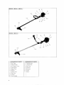
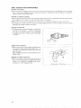
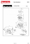
String Trimmer
MODEL RBC230
MODEL RBC260
MODEL RBC261
MODEL RBC310
MODEL RBC311
SPECIFICATIONS
RBC230
Model
RBC260 / RBC261
1,700x 225 x 245
1,700x 540 x 350
(67"x 8~718"x 9~5/8") 167" x 21 lI4" x 13~314")
Dimensions (mm)
(L x W x HI
3.918 6 Ibs)
Weight lkg)
4.6(101 Ibs)
1
Displacement iccl
I
I
1
1
1
I
Fuel tank i I I
I
I
I
Fuel
I
Starting system
Ignition system
I
14/18
14/20
Automatic centrifugal type
22.2
I
1 1
Engine
5 6 112.3Ibs)
~
I
Clutch
1
1,750x 500 x 350
168~7I8"x 19~1
1/16"x 13~3/4"1
4,000 6,000
Revolution of nylon cutting
Gear ratio
RBC310 / RBC311
I
25 4
30.5
15
1 3
Recoil startet
Solid state ignition
06
I
Mixed qas (Gasoline 2 Cycle
NOTICE: S p e c i f i c a t i o n are s u b j e c t t o c h a n g e w i t h o u t n o t i c e .
I
07
EIG
oil
=
08
20 - 25 1)
Thank y o u very m u c h for your patronage in purchasing MAKITA STRING TRIMMER. W e are proud
o f and m u c h c o n f i d e n t in r e c o m m e n d i n g our MAKITA STRING TRIMMER as t h e result o f our long
develop m e nt a n d ample k n o w ledge a n d ex per ien ce.
This booklet refers t o t h e essence w h i c h y o u should learn in order t o demonstrate its outstanding
performance.
We w i s h t h a t you will have sufficient knowledge f r o m this booklet before operating MAKITA STRING
TRIMMER a n d make t h e best use o f it for ever.
SAFETY RULES A N D PRECAUTIONS
Proper s a f e t y precautions m u s t be observed. Like all p o w e r e q u i p m e n t this u n i t m u s t be handled
carefully. D O NOT EXPOSE YOURSELF OR OTHERS TO DANGER. Follow t h e s e sample rules.
1. A l w a y s wear safety goggles for eye protection. Dress properly, d o n o t wear loose clothing or jewelry
t h a t could become c a u g h t in moving parts o f t h e unit. Safe, sturdy, nonskid footwear should always
be worn. Long hair should be t i e d back.
2 . Inspect t h e entire machine f o r loose parts (nuts, bolts, screws, etc.) and any damage. Repair or
replace as necessary.
3 . D O NOT USE any a t t a c h m e n t with this p o w e r head other t h a n t h o s e m a n u f a c t u r e d by t h e
manufacturer o f t h e engine. Serious injury t o t h e user or damage t o t h e engine c o u l d result.
4. Keep t h e handles free o f oil and fuel.
5. A l w a y s use t h e proper handle and hanging b a n d w h e n c u t t i n g .
6. D o n o t smoke w h i l e m i x i n g fuel or filling tank.
7. D o n o t m i x fuel in an enclosed r o o m or near open flames. Assure adequate ventilation.
8 . A l w a y s m i x and store t h e f u e l in a properly marked container t h a t is approved f o r s u c h usage.
9. Never remove t h e fuel tank c a p w h i l e t h e engine is running.
1 0 . Never s t a r t or run t h e engine inside a closed r o o m or building. Fumes f r o m t h e exhaust contain
dangerous carbon monoxide.
1 1 . Never a t t e m p t t o make engine a d j u s t m e n t s w h i l e t h e unit is running and strapped t o t h e operator.
A l w a y s make engine a d j u s t m e n t s with t h e unit resting o n a flat, clear surface.
1 2 . D o n o t use t h e u n i t if it is d a m a g e d or poorly adjusted.
1 3 . Inspect t h e area t o be c u t and remove all debris t h a t c o u l d b e c o m e entangled in t h e n y l o n c u t t i n g
head. A l s o remove any o b j e c t s t h a t t h e unit m a y sling during c u t t i n g .
1 4 . Keep children away. Onlookers should be kept at a safe distance f r o m t h e w o r k area, at least 30 feet.
1 5 . D o n o t use this unit for any job other t h a n those for w h i c h it is intended as described in this manual.
1 6 . D o n o t overreach. Keep proper f o o t i n g a n d balance a t all times. D o n o t r u n unit w h i l e standing
o n a ladder or any other unstable f o o t i n g location.
17. Keep hands and f e e t clear o f t h e nylon c u t t i n g head w h i l e u n i t is in use.
1 8 . D o n o t r u n t h e unit a t high speed w h e n n o t c u t t i n g . During operation, be sure t o keep t h e engine
r o t a t i o n at 6,000 - 8,000 r p m (rated rotation: 7,000 r p m ) . If t h e rotation goes b e l o w this limit,
grass m a y sometimes become caught in t h e nylon c u t t i n g head, w h i c h results in wear o f t h e clutch.
19. D o n o t use t h e u n i t w h e n y o u are tired or under t h e influence o f medications, drugs or alcohol.
20. U s e o n l y nylon c u t t i n g heads w i t h o u t any damage. In particular, whenever it hits at a stone or
any other obstacle s t o p t h e engine and c h e c k t h e n y l o n c u t t i n g head. A broken, or unbalanced
nylon c u t t i n g head m u s t never be used. Follow i n s t r u c t i o n s for changing accessories.
2 1 . D o n o t store in a closed area w h e r e f u e l vapors c a n reach an o p e n flame f r o m h o t w a t e r heaters,
furnaces, etc. Store in a locked, well ventilated area only.
2 2 . Use o n l y replacement parts t h a t are identical t o original e q u i p m e n t parts w h e n servicing t h e unit.
These parts are available f r o m your dealer. The u s e o f any other accessory or a t t a c h m e n t m a y
create a potential hazard, injury t o t h e user and damage t o t h e tool.
2 3 . Clean t h e machine completely, especially, t h e fuel t a n k cap, its surroundings, and t h e air cleaner.
2
24. Children and M i n o r s should n o t operate string t r i m m e r s w i t h metallic c u t t i n g tools, except minors
w h o are properly training and remain under t h e supervision o f a qualified operator.
2 5 . W h e n refueling, be sure t o s t o p t h e engine and c o n f i r m t h a t i t is cooled d o w n . Never refuel w h e n
t h e engine is running or w a r m e d up. W h e n gasoline spills, be sure t o w i p e i t u p completely and
properly dispose o f those materials before starting t h e engine.
26. Stay clear of other workers.
27. Whenever approaching an operator of t h e machine, carefully call his a t t e n t i o n and c o n f i r m t h a t
t h e operator stops t h e engine.
2 8 . Never t o u c h t h e n y l o n c u t t i n g head whenever t h e engine is running. If i t is necessary t o adjust
t h e protector or n y l o n c u t t i n g head, be sure t o stop t h e engine and c o n f i r m t h a t t h e nylon c u t t i n g
head stops running.
2 9 . The engine should be t u r n e d o f f w h e n t h e string trimmer is moved b e t w e e n w o r k i n g areas.
30. Be careful n o t t o h i t t h e nylon c u t t i n g head against stones, or t h e ground. Unreasonable operation
will shorten t h e life of t h e machine as w e l l as create an unsafe environment for yourself and those
around you.
31. Pay a t t e n t i o n t o loosening and overheating of parts. If there is any abnormality o n t h e machine,
stop operation immediately and check the machine carefully. If necessary, have t h e machine serviced
by a qualified service facility. Never c o n t i n u e t o operate a machine w h i c h m a y be malfunctioning.
3 2 . In startup or during operation o f t h e engine, never t o u c h high-temperature parts such as t h e muffler,
t h e high-voltage w i r e or t h e spark plug.
3 3 . For a while after t h e engine is stopped, t h e m u f f l e r is still h o t . Never place t h e machine at any
place where there are flammable materials (dry grass, etc.) or combustible gasses.
34. Pay special a t t e n t i o n t o operation in t h e rain or just after t h e rain as t h e g r o u n d becomes slippery.
3 5 . If you slip or fall t o t h e ground or into a hole, return t h e t h r o t t l e lever immediately.
3 6 . Be careful n o t t o d r o p t h e machine or h i t it against obstacles.
37. Before proceeding t o adjust or repair t h e machine, be sure t o s t o p t h e engine and detach t h e spark
plug c a p f r o m t h e spark plug.
3 8 . W h e n t h e machine is t o be k e p t in storage for a long time, drain f u e l f r o m t h e fuel tank and
carburetor, clean t h e parts, move t h e machine t o a safe place and c o n f i r m t h a t t h e engine is cooled
down.
3 9 . Make periodic inspection t o always assure safe a n d efficient operation. If you need a careful
inspection o f your machine, please c o n t a c t our agent or dealer.
40. Keep t h e machine well away f r o m fire or sparks.
4 1 . Warning: The c u t t e r area is still dangerous w h i l e t h e machine is coasting t o a stop.
42. D o n ' t t r y t o tackle a b i g j o b with an undersized tool.
4 3 . Wear a d u s t mask in d u s t y w o r k conditions.
4 4 . Wear hearing p r o t e c t i o n during loud or extended periods of use.
4 5 . Keep guards a n d protectors in place a n d in w o r k i n g order.
CAUTION !
CAU T I 0N !
CAUTION !
W H E N MIXING GASOLINE W I T H T W O CYCLE ENGINE OIL, USE ONLY GASOLINE W H I C H CONTAINS
NO ETHANOL OR METHANOL (TYPES OF ALCOHOL), THIS WILL HELP TO AVOID POSSIBLE DAMAGE
TO ENGINE FUEL LINES A N D OTHER ENGINE PARTS.
SAVE THESE INSTRUCTIONS.
3
?BC230 I RBC261 I RBC311
(61
\
3BC260 / RBC3lO
I
DESIGNATION OF PARTS
DESIGNATION OF PARTS
Fuel Tank
11
Throttle Lever
Recoil Starter
12
Throttle Wire
Air Cleaner Cover
13
Pipe Case
Stop Button
14
Protector
Spark Plug
15
Gearcase
Muffler
16
Guard
Holder Case
17
Stand
8
Rear Grip
9
Hanger
10
4
I
Front Handle
‘5)
\
ASS E MBLY INSTR UCTI0NS
1. Assembly of engine and pipe case
For RBC230 I RBC261 I RBC311
Remove the protector at the end of the pipe case.
Insert the pipe case into the holder case being sure
t o match the splines of the inner shaft t o those
inside the holder case.
Match the hole in the pipe case t o the hole in the
holder case and fasten the pipe case t o the engine
with damper bolt, wave washer and washer.
(Tightening torque: 70
100 kg.cm; 5
7 ft.lbs)
~
~
171
a 0
141
11 1 Holder case
151 Wave washer
151
161
121 Hole
161 Damper bolt
131 Pipe case
171 Hole
(41Washer
CAUTION :
Securely tighten the damper bolt, which is one of
the important parts mating the engine and machine
body.
For RBC260 and RBC310
Install the pipe case (the end with circular metal
housing) over the clutch assembly and fix with four
socket head bolts and fix tightly with hex wrench.
I l l Pipe case
121 Hex wrench
131 Socket head bolt
2.Mounting of handle
For RBC230 I RBC261 I RBC311
As shown at right, tighten the loop handle with
three socket head bolts.
Mount the handle so that the throttle wire guide
will he oriented t o the right, as viewed from the
engine side.
The standard position of the handle is 200 t o 2 5 0
mm (7-718”
9-718”) from the hanger. Position
the handle according t o a worker’s stature and
working conditions.
~
5
For RBC260 and RBC310
The handle comes in three parts; t w o handles and
one handle holder assembly. (One half of handle
holder is already fitted t o pipe case, the other half
of handle holder is in plastic bag with four socket
head bolts). Place the t w o handles in the half of
handle holder fitted t o pipe case (the flared ends
fit into grooves in handle holder). Place the loose
handle holder over handles and other handle holder
on the pipe case and fix together w i t h the four
socket head bolts, Ensure the throttle assembly is
on correct side and before final tightening, adjust
rake of handle t o suit.
Route the throttle wire and ignition wires through
locations on handle towards engine.
3. Assembly of throttle wire and ignition wire
Remove plastic cover from carburetor.
Insert throttle wire through adjusting screw and
fit nipple of throttle wire into swivel of carburetor.
Adjust the adjusting screw t o take up free play of
wire ensuring the throttle is fully opened when
throttle lever is in high speed position and 2
3
mm (0.079"
0.118") free play when in low
speed position. Re-fit plastic cover.
~
~
Connect the female and male bullet connectors
from throttle assembly t o the male and female
bullet connectors coming from engine.
6
,
4. Mounting of protector and nylon cutting head
~-
I
-
Fasten the protector t o the pipe case with t w o
socket head bolts and clamp. A t this time, the
clamp should be installed on the pipe case with
its projection inserted into the opening between
the gearcase and the pipe case.
( 1 ) Gearcase
(41 Pipe case
12) Clamp
15) Protector
131 Socket head bolt
161 Shaft
To install the nylon cutting head, mount the support washer onto the shaft. Insert the hex wrench
through the hole in the gearcase and turn the
support washer until it will be locked with its notch
(or the shaft will be locked). Then screw the nylon
cutting head onto the shaft by turning it counterclockwise.
Remove the hex wrench.
I l l Hex wrench
(41 Support washer
121 Gearcase
151 Notch
131 Hole
161 Nylon cutting head
7
ENGINE STARTING AND STOPPING PROCEDURES
Starting
When the engine is cold (ie. left stopped for more
than 5 minutes) or when fuel is added t o the engine:
1 ) First place the machine on the ground.
2) Give a gentle push on the primer pump repeatedly
(7 - 10 times) until fuel comes into the primer
pump.
3) Close the choke lever.
I
4) Push the stop switch t o "START"
opposite of "STOP" position).
position (or
( 2 )C h o k e lever
( 1 ) Primer pump
RBC230 / R B C 2 6 1 i RBC311
I
RBC260 / RBC310
( 1I S t o p s w i t c h
5) For RBC230 / RBC261 / RBC311
Squeeze the throttle lever fully. Then release the'
throttle lever while depressing the throttle lock
button. The throttle lever will now be locked in the
"start-up" position.
I RBC230 / RBC261/ RBC311 I
RBC260 / RBC310
For RBC260 and RBC310
Press the "LOCK-OFF" switch before squeezing
the throttle lever. Then squeeze the throttle lever
fully. Release the throttle lever while depressing the
throttle lock button. The throttle lever will now be
locked in the "start-up" position.
1
( 1 ) T h r o t t l e lever
(3)LOCK-OFF s w i t c h
( 2 ) Throttle lock b u t t o n
6) Hold the holder case firmly by your left hand and
give several strong pulls t o the starter by your right
hand.
7) After the engine is started, open the choke lever
fully, checking the engine running condition.
G i v e several s t r o n g pulls t o t h e starter.
* Immediately after the engine is stopped:
Only perform the Nos. 1, 4 and 6 described above.
8
Stopping
Return the throttle lever, and when RPM of engine is lowered, push the stop switch t o "STOP" position. Engine
Wlll stop.
Cautions in handling of engine
Be sure t o use properly mixed fuel.
When the engine is cool, warm it up for one t o t w o minutes.
The carburetor has been adjusted before shipment. If readjustment is required, consult our agent or dealer.
ATTACHMENT AND DETACHMENT OF HANGING BAND
Hanging band fitting procedure. (Fig. 1)
Detachment (Fig. 2 )
In an emergency, pull the release belt strongly upward and you can detach the machine from you.
Be extremely cautious t o maintain control of the machine at this time. D o not allow the machine t o be deflected
toward you or anyone in the work vicinity.
WARN ING:
Failure t o maintain complete control of the machine at all times could result in serious bodily injury or DEATH.
( 1 1 Release belt
Fig. 1
( 2 ) Hanqer ( H a n q l n q m e t a l )
Fig. 2
9
HOW TO OPERATE
The nylon cord will feed out automatically to a pre-determined length when you decrease and increase the engine
speed of your string trimmer. You do not need t o tap the nylon cutting head to let the nylon cord feed out.
If the nylon cord does not feed out automatically, decrease the engine speed fully and then increase it fully.
The nylon cord will feed out automatically. If the nylon cord still does not feed out sufficiently, perform the
same procedures repeatedly until the nylon cord feeds out to the proper length. If the nylon cord is too short
to feed out automatically by performing the above procedures, stop the engine and pull out the nylon cord by
hand or using pliers more than 40 m m (1-9116"). Then perform the above procedures again.
Increase speed
Lowest speed
Decrease speed
Full speed
Increase speed
Lowest speed
Full speed
CAUTION:
NEVER OPERATE THE ENGINE AT HIGH RPM WITHOUT LOAD. With throttle fully opened and no load, the engine
rpm will be very high which can have an adverse effect on the life of the engine.
10
REPLACING THE NYLON CORD
The nylon cord can be easily replaced without removing the nylon cutting head from the String trimmer. Always
stop the engine before replacing the nylon cord.
1 . Loosen the knob in the direction of the arrow
engraved on the knob. Remove the knob and the
cover. Take out the spool.
2. Remove the remaining nylon cord from the spool.
IA
( 1 1 Knob
3. Bend a new nylon cord nearly in half so that there
is approx. 120 mm (4-314") of difference between
the t w o ends.
( 2 )Cover
13) Spool
14) Housing
(51 E y e l e t
7 3
'
=
I
\
&
1 2 0 m m 14-314")
4. Hook the bent portion of the nylon cord into the
notch in the center plate of the spool. Wind the nylon
cords firmly and snugly on the spool in the direction
of the "WIND CORD LH @" engraved on the spool.
(Note)
Do not wind the nylon cords in the opposite direction of the "WIND CORD LH -'' engraved on the
spool. Do not overlap or twist the t w o nylon cords.
They will not feed out properly.
5. Wind both nylon cords firmly and snugly until the
spool is full to the outer edge of the center plate.
Leave approx 120 mm (4.314") of both nylon cords
unwound on the spool. Carefully prevent both nylon
cords from coming loose on the spool. Pass the end
of the shorter nylon cord out through the hole on the
side of the rim of the spool and then back into the
hole as illustrated. Pass the end of the other, longer
nylon cord out through the hole on the opposite side
of the spool as illustrated.
6. Pass the end of each nylon cord out through the
eyelets on opposite sides of the housing. Place the
spool into the housing. Pull the end of nylon cords
while pressing down the spool.
7. Adjust the length of nylon cords so that each nylon
cord extends approx. 8 0 mm - 120 mm (3-118" 4-314") out of the housing. If the nylon cord extends
out too much or does not extend out enough, adjust
the length of nylon cord while raising the spool
slightly within the housing.
11) 80 mm
12
~
1 2 0 mm (3-118''
~
4-314")
8. Set the spool in the housing so that the projections
on the gear plate fit into the notches of the spool.
( 1I N o t c h
12) P r o j e c t i o n
9. Align the small holes on the cover w i t h the eyelets
in the housing and install the cover over the housing
so that the projections on the housing fit into the
notches on the cover.
( 1 1 Hole ( 2 )Cover
(31N o t c h (41Projection
(51 Eyelet
10. Re-install the knob and tighten it securely by turning
in the opposite direction of the arrow engraved on
the knob.
13
DAILY CHECKUP AND MAINTENANCE
Cleaning of air cleaner
If the air cleaner is clogged, remove it and clean If there is excessive dust or dirt adhering t o the air cleaner,
clean it every day A clogged air cleaner may make it difficult or impossible t o start the engine or increase the
engine rotational speed substantially
Cleaning of cooling air passage
Prior t o operation, be sure t o check the cooling air inlet (protection cover), gap between fuel tank and crankcase
and clogging of the cylinder fins with dust. Clean them, if necessary.
Remove the main cover and protection cover and clean the cooling air passage of dust or dirt inside.
If operating the machine with the cooling air passage clogged with dust or dirt, the engine will not be cooled
adequately and engine troubles will result.
Checkup of spark plug
The gap between the t w o electrodes of a spark plug
is 0.6 t o 0.7 mm (0.024"
0.028"). If the gap is
too wide or too narrow, adjust it. If the spark plug
is clogged with carbon or fouled, clean i t thoroughly
or replace it.
~
0 . 6 mm
(0.024"
~
~
0 . 7 mm
0.028")
Supply of oil to gearcase
Remove the hex bolt which plugs the grease hole in
the gearcase. Apply grease (Shell albania No. 2 or
equivalent) t o the gearcase through the grease hole
every 30 hours.
(Genuine Makita grease may be purchased from your
Makita dealer.)
Cleaning of muffler exhaust port
Check the muffler exhaust port (tail pipe) every 5 0
hours. If the exhaust port is clogged with carbon,
remove it by scraping and tapping gently with a
screwdriver or other adequate tools.
( 1 ) Grease hole
14
( 2 )Gearcase
STORAGE
Storage
When storing the machine for a long time, drain fuel
from the fuel tank and carburetor, as follows Drain
all fuel from the fuel tank Dispose of properly and
in accordance with all local laws
Remove the spark plug and add a few drops of oil
into the spark plug hole Then, pull the starter gently
t o assure that an oil film covers the engine inside, then
tighten the spark plug
Clear or blow dirt or dust from the nylon cutting head
and outside of engine, wipe them with a oil-immersed
cloth and keep the machine at a place as dry as
possible Be sure t o wear appropriate eye and face
protection
( 11 D r a i n f u e l
121 H u m i d i t y
CHECKUP ITEMS FOR SAFE OPERATION
Prior t o operation, be sure t o check the following items t o assure safe operation of this machine
No
Common
I
I
1
2
1
1
Apperarance
Bolts, n u t s
C liec k u p
Description
Check point
1
1
By visual inspection, check for damage, crdcks or wear
Check for damdge, cracks, wear or loosening
I
I
-
1 ) Check for damage, cracks or loosening
protector is properly placed in contact w i t h gearcase
Machine
bodv
1 ) Confirm that there are
I
5
I
Handle
1
8
1
Stop switch
I
Muffler,
m u f f l e r Cover
I
I
9
1
I
detach yourself f r o m machine w h e n pulling release belt’
1 ) Does throttle lever work smoothly,
Throttle lever
I
bolts
1 ) Are there any cracks or frdying,
Hanging bdnd
Engine
110 loose
Confirm that handle dttdching bolts are tightened securely
2 ) Can enqine rDm be adlusted b e t w e e n low and hiqh speeds,
1
Does engine s t o p quickly and completely?
1 ) Clean carbon from m u f f l e r
2 ) Check muffler cover for damage or loosening
I
i
1 ) Check damper bolt for secure tightening
2) Confirm that 3 holder case tightening s c r e w s are n o t loosened
15
Makita Corporation
3-11-8, Sumiyoshi-cho,
Anjo, Aichi 446 Japan
7 + 3 ' P + 'In
621 951 3601
PRINTED IN JAPAN
1993-7 E