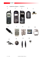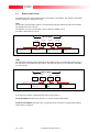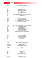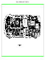
1
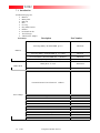
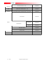
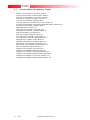
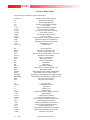
T2282
Level III
Service Manual
T2282
CONTENTS
Page Number
SECTION 1: GENERAL
1.1
1.2
1.3
Introduction
Motorola service policy for T2282 in warranty
General Safety Information
v
vi
vii
SECTION 2: T2282 DESCRIPTION
2.1
2.2
2.3
2.4
Specifications of T2282
T2282 Overview
Connector Pinout
Talk time, Weight and Volume Matrix
2
3
5
5
SECTION 3: FEATURE LIST
3.1
3.2
3.3
3.4
3.5
3.6
3.7
3.9
List of Features available
Phone Book
Call Related Features
Messages
Phone Set Up
Network selection
Call Meters
Accesory Set up
7
7
8
9
10
11
11
12
SECTION 4: DISASSEMBLY & PARTS
4.1
4.2
4.3
4.4
4.5
4.6
Dissasembly Introduction
Recommended Tools
Disassembly Procedure
Assembly procedure
Exploded Parts diagram
Replacement parts
14
14
14
14
19
20
SECTION 5: SIM CARDS AND SECURITY
5.1
5.2
5.3
5.4
5.5
Manual test mode
Live Sim Card
Personality Transfer
GSM Test Command
Identity and Security
22
22
22
23
24
SECTION 6: REPAIR & TEST PROCEDURES
6.1
ii
of 48
Repair introduction
26
T2282
6.2
6.3
6.4
6.5
6.6
6.7
Mechanical repairs
Basic modular troubleshooting
Repair Chart
Software Upgrade
Flexing
Testing on HP8922
26
26
27
29
29
30
SECTION 7: ACCESSORIES
7.1
Introduction
32
SECTION 8: SALES MODELS
8.1
List of available sales models by country
34
SECTION 9: GLOSSARY OF TERMS
9.1
iii
of 48
List of Abbreviations
European Customer Services
36
T2282
SECTION 1: GENERAL
iv
of 48
T2282
1.1
Introduction
This manual is intended for use by technicians familiar with similar types of equipment. It contains all
service information required for the equipment described and is current as of the printing date.
The scope of this document is to provide the reader with basic information relating to the T2282, and
also to provide procedures and processes for repairing the units up to and including Level 2 repair.
Level 1 and 2 repairs involve the following activities to be carried out: •
•
•
•
•
•
•
Unit swap out
Repairing of mechanical faults
Basic modular troubleshooting
Testing and verification of unit functionality
Upgrading software
Flexing units
Initiate warranty claims and send faulty modules to Level 3 or 4 repair centres.
Computer Software Copyrights
The Motorola products described in this instruction manual may include copyrighted Motorola
computer programs stored in semi-conductor memories or other media. Laws in the United States and
other countries preserve for Motorola certain exclusive rights for copyrighted computer programs,
including the exclusive right to copy or reproduce in any form the copyrighted computer program.
Accordingly, any copyrighted Motorola computer programs contained in the Motorola products
described in this instruction manual may not be copied or reproduced in any manner without the
express written permission of Motorola. Furthermore, the purchase of Motorola products shall not be
deemed to grant either directly or by implication, estoppel, or otherwise, any license under the
copyrights, patents or patent applications of Motorola, except for the normal non-exclusive, royalty
free license to use that arises by operation of law in the sale of a product.
v
of 48
T2282
1.2
Motorola Service Policy for T2282 in warranty
1.2.1
Warranty:
Product will be sold with the standard 12 months warranty terms and conditions. Accidental damage
misuse, retailers extended warranties will not be supported under warranty. Non warranty repairs will
be available at agreed fixed repair prices.
Proof of purchase will be required to validate warranty claims.
1.2.2
Out of Box Failure Policy
The standard OOB failure criteria will apply. Customer units that fail very early on, after date of sale,
are to be returned to Manufacturing for root cause analysis, to guard against epidemic criteria.
Manufacturing to bear the costs of early life failure.
1.2.3
Product Support
Customers original units will be repaired but not refurbished as standard. Appointed Motorola Service
Hubs will perform warranty and non-warranty field service for level 2 (assemblies) and level 3 (limited
PCB component). The Motorola HTC centres will perform level 4 (full component) repairs.
1.2.4
Customer Support:
This will be available through dedicated Call Centres and In Country Help Desks.
Product Service training should be arranged through the local Motorola Support Centre.
1.2.5
Replacement Parts Ordering
Only centres authorized to carry out repairs will be able to purchase spare parts. Orders for spare parts
from Hub’s and Hi-Tech Centres should be placed with the regional Motorola Parts Distribution
Centre.
vi
of 48
T2282
1.3
General Safety Information
1.3.1 Portable Operation
• DO NOT hold the radio so that the antenna is very close to, or touching, exposed parts of the body,
especially the face or eyes whilst transmitting. The radio will perform best if it is held in the same
manner as you would hold a ‘land’ telephone handset, with the antenna angled up and over your
shoulder.
•
DO NOT operate the portable phone in an aircraft. Switch off your telephone. The use of a cellular
telephone in an aircraft may be dangerous to the operation of the aircraft, disruption of the Cellular
Network may occur, and is illegal. Failure to observe this instruction may lead to a suspension or
denial of Cellular Telephone Service to the offender, or legal action, or both.
1.3.2 Mobile/Portable Operation - Telephone use in Vehicles:
• All equipment must be properly grounded according to installation instructions for safe operation.
•
Users are advised to turn off their equipment when at a refueling point.
•
Safety is every driver’s responsibility. Cellular telephones should only be used in situations in
which the driver considers it safe to do so.
1.3.3 General
• DO NOT allow children to play with any radio equipment containing a transmitter.
•
DO NOT operate this equipment near electrical blasting caps or in an explosive atmosphere.
Mobile Telephones are, under certain conditions, capable of interfering with blasting operations.
When you are in the vicinity of such work, look out for and observe signs cautioning against
mobile radio transmission. If transmission is prohibited, you must turn off your mobile telephone
to prevent any transmission.
In standby mode the mobile telephone will automatically transmit to acknowledge a call if it is not
turned off.
•
Refer to the appropriate section of the product user manual for additional pertinent safety
information
•
All equipment should be serviced only by a Motorola qualified technician.
vii of 48
T2282
SECTION 2:
T2282
DESCRIPTION
1
of 48
T2282
2.1
Specifications of T2282
General
Function
Frequency Range GSM
1850.2-1909.8 MHz Tx
1930.2-1989.8 MHz TX
Channel Spacing
Channels
Modulation
Transmitter Phase Accuracy
Duplex Spacing
Frequency Stability
Operating Voltage
200 kHz
274 PCS, carriers with 8 channels per carrier
GMSK at BT = 0.3
5 Degrees RMS, 20 Degrees peak
45 MHz GSM / 95MHz DCS
+ 0.10 ppm of the downlink frequency (Rx)
Mid Rate Charger: 4.0V, 350mA +/-10%
(Open Circuit Voltage =13.0V +/- 10%)
EIHF or VPA Supply:
Mid Rate = 6.25V, 400mA +/-5%
Fast Rate = 6.25V, 900mA +/-5%
Battery Operating Voltage: 2.85V(Radio Shut Down voltage)
To 5.1V Max (Radio Over Voltage Protect)
Typically 300 mA avg, 1.0A peak
Typically 7.0 mA (DRX2)
130mm x 47mm x 27mm
120cc with Battery
140g with Battery
-10C to +55C
Transmit Current
Stand-by Current
Dimensions
Size (Volume)
Weight
Temperature Range
Transmitter
Function
RF Power Output
Output Impedance
Spurious Emissions
Receiver
Function
RF Level
RX bit error rate (100 k bits)
Channel Hop Time
Time to Camp
Speech Coding
Function
Speech Coding Type
Bit Rate
Frame Duration
Block Length
Classes
Bit Rate with FEC Encoding
2
Specification
of 48
Specification
33 dBm + 2dB GSM/ 30 dBm + 2 dB DCS
50 ohms (nominal)
-36 dBm from 0.1 to 1 Ghz
-30 dBm from 1 to 4 Ghz
Specification
-102 dBm GSM / -100 dBm DCS
< 2%
500 microseconds
Approximately 5-10 seconds
Specification
Regular Pulse Excitation / Linear Predictive Coding with Long
Term Prediction. (RPE LPC with LTP).
13.0 k bps
20 ms
260 bits
Class 1 bits = 182 bits. Class 2 bits = 78 bits
22.8 k bps
T2282
2.2
T2282 Overview
The Talkabout Z is the new low cost products aimed at a wide audience and is branded in the talkabout
range. For people whose core needs are personal connections, peace of mind that others can reach
them, people who balance their family, social and business needs.
There will be 2 versions of this product the T2282
The T2282 will incorporate many new features that were, in the past unavailable to the low cost
products. These are:
•
WAP with UP 3.1 Microbrowser – available through network provider to access all WML pages
on the internet.
v The menu, with the aid of the soft icons will help guide the user to browse through most of the
popular WML sites
v Only possible to download small images or icons
v Information cannot be saved as a file
•
Intergrated Headset – Mono or Stereo
•
No external accesory connector – now removed, all flashing and flexing to be delivered through 8
pin socket in rear of phone below batteries
•
External Charger Jack socket
•
96 X 64 Graphics Display with 13 Soft Icons
•
Single Cell Ni MH Batteries
•
Single Band GSM 1900
•
SIM toolkit V2.2.0
•
New Charger circuitry
3
of 48
T2282
Lens with Talkabout
Brand
Fig 2.1 Mechanical
pictorial Overview
Escutcheon
Recess
Antenna
Keypad
Speaker
Ports
Headset
Connector
Screw
Locations
Vol Up / Down
Antenna
SIM Slot
Auxiliary RF
Test Port
Flashing / Flexing
test Connector
Batt
Contacts
Antenna
Headset Adapter
Volume
Buttons
Battery
Cover
Charger
Socket
Antenna
4
of 48
T2282
2.3 Connector Pinout
1
2
12345678-
2.4
5
6
7
8
TP866 - GND
TP865 – B+
TP875 – ON*
TP877 - UPLINK
TP878 - DOWNLINK
TP864 – DSC_EN
TP1000 – 152KHz
TP1001 – FM_RSSI
Talk Times, Weight, Dimensions and Volume Matrix
X
Volume
(cubic
cm)
120
5
3
4
of 48
White holographic film on display
Weight
Talk Time Standby time
(grams)
(minutes)
(hours)
140
140
100
Dimensions
(mm)
With Battery type:
130 x 47 x 27
700 mAh AAAL NiMH
Battery Cells
T2282
SECTION 3: FEATURE LIST
6
of 48
T2282
3.1
List of Features Available
Below are the list of Menu functions available at present.
Menu
1st Generation Menu
Phone Book
Network
Selection
Call Related
Features
Call Meters
Messages
Phone Setup
nd
2 Generation Menu
3rd Generation Menu
4th Generation Menu
Th Generation Menu
6th Generation Menu
Accessory
Setup
Access
Internet
PHONE BOOK
Personal Numbers
1.Last Calls made
Last 10 Calls
1.Call Number
2.Time and Date
3.Add to Phone memory
4.Add to SIM Memory
Last Calls Received
Find Entry
by Name
Enter Name
Find Entry
By Location
Enter Location
1.Call Number
2.Modify Name or
number
3.Erase name or
number
Erase all Numbers
Add Entry
My phone number(s)
Fixed dialing
Setup
fixed
Dialing
Show Services
Enter
Pin2
1.To Phone Memory
2.To SIM memory
3.To Fixed Dial list
One-Touch
Dial Setting
7
Check Capacity
View fixed dial list
of 48
1.On
2.Off
3.Edit Entry
4.Add Entry
5.Erase Entry
Prevent access
1.No memory restrictions
2.To SIM card memory
T2282
CALL RELATED
FEATURES
Show battery meter
Restrict my
Phone number
1.Show ID on next call
2.Restrict ID on next call
Call Diverting
Call waiting
Call Barring
1.On
2.Off
Bar outgoing calls
1.Int’l Calls
2.Int’l Calls Except home
3.All Calls
4.Off
1.When Roaming
2.All Calls
3.Off
Bar Incoming Calls
Change Bar password
Cancel all barring
Divert Voice calls
Divert when unavailable
1.On
2.Off
Divert all Voice calls
1.On
2.Off
Detailed Diverting
8
of 48
If Busy
1.On
2.Off
If not reachable
1.On
2.Off
If No Answer
1.On
2.Off
T2282
Messages
Call Voicemail
Received messages
Go to Next message
Delete Message
Return Call
Edit Message
1.Send Message
2.Store Message
Reply to message
Delete all messages
Outgoing Messages
Go to next message
Send message
Edit message
1.Send message
2.Store message
Delete message
Cell broadcast
On
Off
Channel List
Message Settings
1.Voicemail Number
2.Service Centre
3.Expiry Period
4.Outgoing message type
Message Editor
Edit Message
1.Channel Index
2.Delete all channels
Send message
Store Message
9
of 48
T2282
PHONE SETUP
Select phone line
1.
Line 1
Line 2
2.
Adjust Ring volume
Set Ringer Tone
Standard Tone
.
.
Music Tone
Set Ringer Tone 2
Ringer on or Off
1.On
2.Off
Phone Lock
Automatic Lock
Adjust Contrast
Lock Now
Change Unlock mode
Change SIM PIN2 Code
Require SIM card pin
1.On
2.Off
3.Change SIM pin Code
New security code
Extended menus
Language Selection
10
of 48
1.On
2.Off
English
.
.
Automatic
Battery saving mode
1.On
2.Off
Select Keypad tones
1.Normal Tones
2.Single Tones
3.No Tones
Phone Status
1.Status review
2.Master reset
3.Master Clear
1.On
2.Off
T2282
NETWORK
SELECTION
Available
Networks
1.Register Now
2.Make Preferred
Network Search
Registration
Preferences
1.Automatic Search
2.Manual Search
Frequency of
Search
1.Slow Search
2.Medium Search
3.Fast Search
4.Continuous Search
Add network
to List
1.Choose From Available
2.Choose From Known
3.Add new Network Code
Find New
Networks
Show List of
Networks
1.Move to New Location
2.Delete Selection
Change Band
1.Change to 900 / 1800
2.Change to 900
3.Change to 1800
Preferred
Networks
CALL METERS
Show call timers
1.Show last call
2.Total for all calls
3.Reset all timers
Set audible Call Timers
Single Alert Timer
Repetitive Timer
Set in call Display
Lifetime Timer
Show call Charges
Call Charge Settings
11
of 48
1.On
2.Off
1.On
2.Off
1.Show time per call
2.No in call display
3.Show Total Call Charges
4.Show Charge per Call
1.Show last Call
2.Total for all calls
3.Credit remaining
Reset Call charges
Set total Charge Limit
1.On
2.Off
Set Charge Type
1.Units
2.Currency
T2282
ACCESSORY
SETUP
NB. THIS MENU IS ONLY AVAILABLE WITH EITHER HEADSET PLUGGED IN OR
WHEN INSTALLED IN A CAR KIT.
Automatic Answer
12
of 48
1.On
2.Off
T2282
WAP
ACCESS
WAP – Wireless Application Protocol: THIS IS A NETWORK AND SUBSCRIPTIONDEPENDANT FEATURE THAT WILL NOT WORK WITHOUT PRE ARRANGEMENT WITH
THE NETWORK PROVIDER. ALSO WAP ON THE T2282 CAN ONLY ACCESS WML PAGES
(WML, a different mark up language to HTML) AND CAN ONLY DOWNLOAD AND DISPLAY
SMALL GRAPHICS AND IMAGES.
MSC – Mobile
Switching Center
Service Provider
WML Internet
Sites
WAP
Gateway
BTS
As can be seen, there are various stages through the path that access must be obtained either through
the network provider or / and the internet access provider (WAP Gateway).
WAP access will be the first item upon pressing the menu key. From this point on the soft propts above
the top row of keys will be your guide i.e the cancel button will now be the ‘back’ button not the cancel
button.
On accessing the WAP menu you will be given the folling screen
The access baud rate is at the standard 9600bps and there will be a
Password check as well as a internal security memory check.
All information on setting the WAP session up is contained within
the user manual.
Menu Title
1.Shares
2.Weather
3My Motorola
Pre-set up
XML pages
Back
Soft Keys that indicate
C / menu / OK keys
C
13
of 48
View
Menu
OK
T2282
SECTION 4: DISASSEMBLY &
PARTS
14
of 48
European Customer Services
T2282
4.1 Disassembly Introduction
TheT2282 is held together by 6 screws, 2 uppermost and 4 within the battery casing. Ensure care is
taken when removing the LCD from the main PCB as the flex is very delicate and can be easily
damaged.
Ensure that a properly grounded high impedance conductive wrist strap is used whilst performing any
tasks during the disassembly and assembly of the unit
Avoid stressing the plastics in any way to avoid damage to either the plastics or internal components.
!! CAUTION !!
Many of the intergrated devices used in this equipment are vulnerable to damage from
electro-static charges. Ensure that adequate static protection is in place when handling,
shipping and servicing the internal components of this equipment.
4.2
Recommended Tools
The following tools are recommended for use during the assembly / disassembly of the T2282
•
Anti-static Mat Kit - 0180386A82, includes:
Antistatic mat 66-80387A95
Ground Cord 66-80334B36
Wrist Band 42-80385A59
•
•
Plastic Bladed Tool SLN7223A
T6 Torx Driver
4.3
Disassembly Procedure
The following set of diagrams will demonstrate the correct sequence and action required to disassemble
the T2282
The use of the exploded diagram on page 19 and 20 may be of some assistance for part recognition.
4.4
Assembly Procedure
Once the unit is disassembled and the repair is carried out, the unit must then be reassembled, this is
carried out in the exact reverse order as the disassembly.
15
of 48
European Customer Services
T2282
1. Remove battery door
2. Remove Batteries
by pressing down on
latch and pulling back
3. Remove antenna by
rotating anti-clockwise
16
of 48
4. Unscrew 6 retaining
screws using T6 Torx driver –
find screw locations on page 4
European Customer Services
T2282
5. Remove rear
6. Slide plastic tool in between front
housing from unit.
housing and PCB and prise PCB out.
7. Remove the rubber side
8. Remove Keypad
panels from each side of the
unit.
17
of 48
European Customer Services
T2282
9. Remove alert speaker
10. Carefully prise display LCD
from front housing
from main board by releasing
catches on each side of LCD frame
11. Carefully lift the flip of
12. Remove the alert by sliding the
the ZIF connector and
remove the flex Note: The
flex is very fragile.
plastic tool below the alert speaker and
prizing upwards
18
of 48
European Customer Services
T2282
4.5
Exploded Parts Diagram
1
11
19
3
2
6
of 48
SUG0097AA
4
5
7
8
9
12
13
14
European Customer Services
10
T2282
4.5 Replacement Parts
Xcvr Item Number
Spare Xcvr Number
Flip
Front Housing
Rear Housing
R-side Cam Shaft
L- side Cam shaft
R-Hinge Cover
Stubby Antenna
20
of 48
1
2
3
4
5
6
7
8
SUG0097AA
SA1014AQV3B1
0185815K03
0185686K01
0185848K01
Display Assy
Keypad
SIM card holder
Alert Grommet
Mic
Mic Grommet
Flex Cover
4709038K02
European Customer Services
9
10
11
12
13
14
15
SYN8131A
3885692K01
0187436K01
0585852K01
5009135L07
0585853K01
5403801S01
T2282
SECTION 5: SIM CARDS AND
SECURITY
21
of 48
European Customer Services
T2282
5.1 Manual Test Mode
The GSM Motorola T2282 is equipped with a manual test mode capability. This capability allows
service personnel to take control of the unit, and by entering certain keypad commands, make the unit
performs desired functions.
To enter the manual test command mode, a GSM / DCS mini test sim (Part No 8102430Z04) must be
used.
The test sim is inserted into the SIM slot in the side of the phone (See figure 6.1), the battery should
then be inserted and the unit powered on. The # button should then be pressed for approximately 3
second until ‘test’ appears on the display, and the correct commands must then be followed.
SIM CARD SLOT
Figure 6.1 SIM Card insertion
5.2 Live Sim Card
A SIM (Subscriber Identity module) card will be required to access the existing local GSM / DCS
cellular network, or remote networks when travelling. (If the roaming agreement has been made with
the provider.)
The SIM card contains all the data necessary to access GSM services, and also:
• The ability to store user information such as phone numbers etc…
• All information required by the network provider to provide use to the network
5.3
Personality Transfer
No personality transfer available on this product.
22
of 48
European Customer Services
T2282
5.4
GSM Test Commands
This is a list of Level 1 and 2 Test commands available to T2282
Table 5.1 Test commands
GSM Test Commands
Key Sequence
Test Function/Name
#(hold down for 2 seconds)
Enter manual test mode
01#
Exit manual test mode
07x#
Mute RX audio path
08#
Unmute RX audio path
09#
Mute TX audio path
10#
Unmute TX audio path
15x#
Generate tone
16#
Mute tone generator
19#
Display S/W version number of Call Processor
20#
Display S/W version number of Modem
36#
Initiate acoustic loopback
37#
Stop test
38#
Activate Mini SIM
39#
Deactivate Mini SIM
43x#
Change audio path
51#
Enable sidetone
52#
Disable sidetone
54X#
Show Service Indicator LED
(Flip must be Closed)
57#
Initialize non-volatile memory
58#
Display security code
58xxxxxx#
Modify security code
59#
Display lock code
59xxx#
Modify lock code
60#
Display IMEI
980# / 981#
DCS / GSM mode
99#
Display all display pixels
0 - Off / 1 – Red / 2 – Green / 3 – Amber
15XX#
91
23
Constant Ringer
of 48
0 or Omitted
1
2
European Customer Services
36XX#
Full Rate
Enhanced Full rate
Half Rate
T2282
5.5
Identity and Security
Each Motorola T2282 will be labelled with various number configurations. The following information
describes what these configurations mean.
MSN
The mechanical Serial Number (MSN) is an individual unit identity number and will remain with the
unit throughout the life of the unit.
The MSN can be used to log and track a unit on Motorola’s EPPRS system.
The MSN is divided into 4 sections.
MSN 10 Digits
3 digits
APC
Account Product Code
I.e. Startac 130
1 digit
DC
Distribution Center
I.e. Easter Inch
2 digits
DC
4 digits
SNR
Date Code: Year and
Month of Shipment
Units individual serial
number
Figure 5.2 MSN label breakdown
IMEI
The International Mobile station Equipment Identity (IMEI) number is an individual number unique to
the PCB and is stored within the unit’s memory. The following figure gives a description of the make
up of this number.
IMEI 16 Digits
Type Approval code
6 digits
2 digits
6 digits
2 digits
TAC
FAC
SNR
IU
Distribution Center
factory code
Individual PCB Serial
Number
Internal use – spare
digits
Figure 5.3 IMEI label breakdown
Some other label number configurations that will be present will be: XCVR NUMBER: Identifies type of product. i.e. T2282 (Usually SWF number)
PACKAGE NUMBER: Determines type of equipment, mode in which it was shipped and language
with which it was shipped.
24
of 48
European Customer Services
T2282
SECTION 6: REPAIR AND TEST
PROCEDURES
25
of 48
European Customer Services
T2282
6.1 Repair Introduction
The T2282 is divided into 3 main sections when it comes to part replacability: The Flip which contains
the speaker,battery connections, RTC battery and Vibrator. The housings that contain the main PCB
which contains RF / Logic circuitry. The third component is the the keypad and Display Assy. If the
RF / Logic board is required to be changed then a full service tranceiver should be ordered as there is
no replacement PCB available. Also a personality transfer would be necessary.
6.2
Mechanical repairs
Assembly replacement level troubleshooting and repair of the T2282 is limited to isolation and
replacement of the main mechanical parts only (See Exploded parts diagram and associated parts list)
6.3
Basic Modular Troubleshooting
The troubleshooting information in Table 2 shows some typical malfunction symptoms, and for the
corresponding verification and repair procedures refer to the disassembly instructions located in the
disassembly section of this manual. (Section 5).
NOTE
26
of 48
Defective Logic/RF assemblies must be replaced
with pre-tested, pre-phased assemblies
European Customer Services
T2282
6.4
Repair Chart
Table 2. GSM T2282 Cellular Telephone: Troubleshooting and Repair Chart. (Assembly Replacement
Level).
SYMPTOM
Personal telephone will not turn on or
stay on
2. Personal telephone exhibits poor
reception and/or erratic operation (such
as calls frequently dropping, weak
and/or distorted audio, etc.).
3. Display is erratic, or provides
Partial or no display.
PROBABLE CAUSE
a) Battery pack either discharged
or defective
Replace batteries with known good cells. Power unit
on. If unit powers on OK replace batteries.
If battery is not at fault, proceed to b.
b) Battery connectors open or
misaligned.
Visually inspect the battery connectors on the rear
housing top and bottom. Check for bad alignment or
dirty contacts. Re-align, clean and, if necessary,
replace the rear housing. If battery connectors are not
at fault, proceed to c
c) Logic/RF Board Assembly
Defective.
Remove the Logic/RF Assembly. Substitute a known
good assembly and temporarily reassemble the unit.
Depress the PWR button; if unit turns on and stays
on, disconnect the dc power source and reassemble
the telephone with the new Logic/RF Board
assembly. If unit does not power up proceed to d)
d) Display circuit failure
Disassemble unit and remove LCD module and
insert known good module. Insert Battery and
depress PWR button. Ensure unit stays on, if OK
reassemble unit in new housing assembly
a) Antenna is defective
Check to make sure that the antenna is properly
inserted into the front housing. If OK, substitute a
known good antenna. If the fault is still present,
proceed to b.
b) Logic/RF Board Assembly
Defective.
Replace Logic/RF Assembly (refer to symptom 1c).
Verify that the fault has been cleared and
Re-assemble the unit with the new PCB.
a) Mating connections to / from
Display PCB.
Dissasemble unit, and remove display module from
main PCB, check connector for any signs of
corrosion or damage. If damaged proceed to c)
b) Display Module is
Defective.
Substitute a known good Display Module onto the
suspect main board and connect to DC Pwr supply
depress PWR and ensure display is now correct, If
Ok rebuild unit with new Display assembly. If
display assembly is not at fault proceed to c.
Replace Logic/RF Assembly (refer to symptom 1c).
Verify that the fault has been cleared and
Re-assemble the unit with the new PCB.
c) Logic/RF Board Assembly
Defective.
27
of 48
VERIFICATION AND
REMEDY
European Customer Services
T2282
SYMPTOM
4. Incoming call alert transducer
audio, distorted or volume is too
low.
5. Personal telephone transmit audio
is weak, (usually indicated by called
parties complaining of difficulty in
hearing voice from personal phone).
PROBABLE CAUSE
a) Faulty alert Transducer
VERIFICATION AND REMEDY
Replace Alert Transducer from rear housing refer to
disassembly procedure.If not Alert then proceed to b)
b)Main RF / Logic PCB
defective
Replace Logic/RF Board Assembly (refer to
symptom 1c). Verify that the fault has been cleared
and re-assemble the unit with the new PCB.
a) Microphone connections to
the main RF / Logic board are
defective.
Gain access to the Microphone as described in the
DISASSEMBLY instructions in this manual. . Check
connections. If connector is faulty proceed to c if the
connector is OK, proceed to b.
b) Microphone defective
Gain access to microphone .Disconnect and
substitute a known good Microphone. Place a call
and verify as heard by called party. If good, reassemble unit with new Microphone. If Microphone
is not at fault, re-install original Microphone and
proceed to c.
Replace Logic/RF Board Assembly (refer to
symptom 1c). Verify that the fault has been cleared
and re-assemble the unit with the new PCB.
Ensure pads on PCB are clean and that speaker
contacs are sat almost vertical to each other. If Ok
replace with known good speaker and check for call
quality. If still poor proceed to c)
Attempt a re-phasing of the unit and recheck the
symptom. If symptom is the same but unit re-phases
correctly, check to make sure the antenna connector
is correctly soldered to the main board and that the
antenna is fitted correctly. If ok, substitute a known
good antenna assembly. If this does not cure the
fault, re-install the original antenna then proceed to
d).
c) Logic/RF Board Assembly
defective.
6. Personal telephone receive audio
is weak and/or distorted. (From
speaker)
Dirty Contacts / Misalignment
of contacts or faulty speaker.
c) Antenna assembly is
defective.
7. Personal telephone will not
recognize/accept SIM card
d) Logic/RF Board Assembly
Defective.
d) Replace Logic/RF Assembly (refer to symptom
1c). Verify that the fault has been cleared and Reassemble the unit with the new PCB.
a) SIM card defective
Initially check that the contacts on the card are not
dirty. Clean if necessary, and check if fault has been
eliminated. If the contacts are clean, insert a Known
good SIM card into the unit. Power up the unit and
confirm whether or not the card has been accepted. If
the fault no longer exists, the defective SIM card
should be replaced. If the SIM card is not at fault,
proceed to b.
Replace Logic/RF Board Assembly (refer to
symptom 1c). Verify that the fault has been cleared
and re-assemble the unit with the new PCB.
c) Logic/RF Board Assembly
Defective.
SYMPTOM
9. Internal Charger not working
PROBABLE CAUSE
a) Batteries faulty
a) Faulty charger circuit on main
board defective
10. No / Weak audio when using
28
of 48
a) Headset not fully pushed
VERIFICATION AND REMEDY
Replace suspect batteries with known good items.
Insert charger and ensure battrey charging icon
flashes if OK, replace batteries if batteries still do not
charge proceed to b)
Replace Logic/RF Board Assembly (refer to
symptom 1c). Verify that the fault has been cleared
and re-assemble the unit with the new PCB.
Fully ensure the ‘click’ is felt on the jack socket. If
European Customer Services
T2282
headset
6.5
home
b) Faulty Jack Socket /
Defective PCB
still no audio proceed to b)
Replace Logic/RF Board Assembly (refer to
symptom 1c). Verify that the fault has been cleared
and re-assemble the unit with the new PCB.
Software Upgrade
For information on setting up and equipment required for the flashing of software, contact should be
made with the local technical support engineer.
6.6
Flexing
For information on setting up and equipment for flexing, contact should be made with the local
technical support engineer.
6.7
Testing on HP8922
For the T2282 a completely different connector to all previous models, the only external connectors to
the customer are the Headset connector and the charger socket. For test the connector shown is used
flashing and flexing and the auxiliary port is used for RF tests.
29
of 48
European Customer Services
T2282
Fig 6.1 T2282
External Socket
30
of 48
Fig 6.2 Flashing /
Flex cable
European Customer Services
Fig 6.3 Flash Cable
(with Power leads)
T2282
SECTION 7: ACCESSORIES
31
of 48
European Customer Services
T2282
7.1 Introduction
Included in this page are:
• Batteries
• Battery Door
• Belt Clip
• Boot
• Car Clip
• Easy-Install Car Kit
• Headset
• Pro-Install Car Kit
• Travel Charger
• Vehicle Power Adaptor
Accessory
Description
Part Number
AAA Long Battery 700 mAh NiMH (Q/A: 3)
SNN5542
AAA Long Battery 700 mAh NiMH (Q/A: 3)-China
SNN5541
AAA Long Battery 700 mAh NiMH (Q/A: 3)-Portugese
SNN5540
Batteries
NOTE: Q/A = Quantity per Assembly
Battery Door - Z Look
SHN7282A
Battery Door - R Look
SHN7426A
Battery Door
350 mAh Economy Travel Charger (Fixed Plug):
Travel Charger
32
of 48
Argentina
SPN4678A
Australia
SPN4683A
Brazil 220V
SPN4679A
Brazil 110V
SPN4707A
China (w/o holes in the blades)
SPN4677A
Euro
SPN4682A
India ( 5 Amp)
SPN4684A
U.K.
SPN4680A
U.S.
SPN4681A
European Customer Services
T2282
Belt Clip-On System - Z Look
SYN8092A
Belt Clip-On System - R Look
TBD
VPA
Vehicle Power Adapter (Dual Current)
SYN8087A
Easy-Install Car Kit
Easy-Install Hands Free Car Kit (Analog Audio)
SYN8088A
Car Clip
Car Clip (Phone Holder) compatible w/Belt Clip-On System
SYN8184A
Boom Headset
SYN8146A
Belt Clip
Headset
Blue Pouch
SYN6962A
Jewel Case
SYN7453A
Plastic Bag
SYN8390A
Earbud Headset
Boot
33
of 48
Retractable Headset
SYN8284A
Headset (Mono)
SYN6962A
Stereo for FM Radio (for GSM R look only)
SYN8086A
Rubber Boot- R Look
SYNXXXXX
European Customer Services
T2282
SECTION 8: SALES MODELS
34
of 48
European Customer Services
T2282
8.1
List of Available Sales models by Country
Australia SA1306AB1B1 (V-Dot, Black, SIM) V0
Australia SA1293AB1B1 (Talkabout, Black, SIM) V0
Euro Pkg1 SA1307AB1B1 (V-Dot, Black, Cambodia,
Indonesia, Laos, Pakistan, Sri Lanka, Vietnam) V0
Euro Pkg1 SA1294AB1B1 (Talkabout, Black,
Cambodia, Indonesia, Laos, Pakistan, Sri Lanka,Vietnam) V0
Euro Pkg2 SA1308AB1B1 (V-Dot, Black, Bangladesh, Brunei, Mauritius) V0
Euro Pkg2 SA1295AB1B1 (Talkabout, Black,
Bangladesh, Brunei, Mauritius) V0
Hong Kong SA1363AB1X1 (V-Dot, Black) V1
Hong Kong SA1360AB1X1 (Talkabout, Black) V4
India SA1309AB1B1 (V-Dot, Black) V0
India SA1296AB1B1 (Talkabout, Black) V0
New Zealand SA1310AB1B1 (V-Dot, Black) V0
New Zealand SA1297AB1B1 (Talkabout, Black) V0
Philippines SA1311AB1B1 (V-Dot, Black) V0
Philippines SA1298AB1B1 (Talkabout, Black) V0
Plain Package SA1312AB1B1 (V-Dot, Black) V0
Plain Package SA1299AB1B1 (Talkabout, Black) V0
PRC SA1362AB1X2 (Talkabout, Black) V2
Singapore SA1313AB1B1 (V-Dot, Black) V0
Singapore SA1300AB1B1 (Talkabout, Black) V0
Thailand SA1315AB1B1 (V-Dot, Black, SIM/AIS) V0
Thailand SA1302AB1B1 (Talkabout, Black, SIM/AIS)V0
Thailand SA1314AB1B1 (V-Dot, Black, SIM/TAC) V0
Thailand SA1301AB1B1 (Talkabout, Black, SIM/TAC)V0
35
of 48
European Customer Services
T2282
SECTION 9: GLOSSARY OF
TERMS
36
of 48
European Customer Services
T2282
9.1 List of Abbreviations
Those marked ** are Motorola specific abbreviations.
A Interface
A3
A5
A8
AB
A-bis
ACCH
ACSE
AGCH
AMPS
AOC
ARFCN
ARQ
ASIC
AUC
AUT (H)
Interface between MSC and BSS
Authentication algorithm
Stream cipher algorithm
ciphering key generating algorithm
Access Burst
Interface between BSC and BTS
Associated Control Channel
Association Control Service Element
Access Grant Channel
Advance Mobile Phone System
Advice of charge
Absolute Radio Frequency Channel Number
Automatic Request for retransmission
Application Specific Integrated Circuit
Authentication Center
Authentication
BA
BAIC
BAOC
BCC
BCCH
BCD
BCU
Bm
BN
BS
BSC
BSIC
BSS
BSSAP
BSSC
BSSMAP
BSSOMAP
BSU
BTS
BCCH Allocation
Barring of All Incoming Calls
barring of all Outgoing Calls
Base Transceiver Station (BTS) Color Code
Broadcast Control Channel
Binary Coded Decimal
BTS Control Unit **
Full-rate traffic channel
Bit Number
Base Station
Base Station Controller
Base Transceiver Station Identity Code
Base Station System
BSS Application Part (DTAP and BSSMAP)
Base Station System Control Cabinet **
Base Station Systems Management Application Part
BSS Operation and Maintenance Application Part
Base Site Controller Unit **
Base Transceiver Station
CA
CBCH
cc
cc
CC
CCBS
CCH
CCCH
CDMA
CFS
CFU
CLIP
CLIR
CM
COLP
COLR
CONF
37
of 48
Call Allocation
Call Broadcast Channel
Call Control
Country Code
Cellular Cassette
Completion of Calls to Busy Subscribers
Control Channel
Common Control Channel
Code Division Multiple Access
Call Forwarding on mobile Subscriber busy
Call Forwarding Unconditional
Calling Line Identification Presentation
Calling Line Identification Restriction
Connection Management
Connected Line identification Presentation
Connected Line identification Restriction
Conference Call add on
European Customer Services
T2282
CSPDN
CUG
CW
Circuit Switched Public Data Network
Closed User Group
Call Waiting
DB
DBS
DCCH
DET
DFE
DISC
DL
Dm
Dm
Dp
DRCU
DRX
DTAP
DTE
DTMF
DTX
Dummy Burst
Distributed Base Station **
Dedicated Control Channel
Detach
Decision Feedback Equalizer
Disconnect
Data Link (layer)
Control Channel (ISDN terminology applied to mobile service)
Signaling channel
Dialed Pulse
Diversity Radio Channel Unit**
Discontinuous Reception
Direct Transfer Application Part
Data Terminal Equipment
Dual Tone Multi-Frequency (tone signaling type)
Discontinuous Transmission
E
Eb/No
EC
Ec/No
EGSM
EFR
EIR
EIRP
EMC
EMX
ETSI
erlang
Energy per Bit/Noise floor
Echo Canceller
Ratio of energy per modulating bit to the noise spectral density
Extended Group special Mobile
Enhanced Full Rate
Equipment Identity Register
Effective Isotropic Radiated Power
Electromagnetic Compatibility
Electronic Mobile Exchange **
European Telecommunications Standards Institute
FACCH
FACCH/F
FACCH/H
FB
FCCH
FEC
FN
FR
FTAM
GCC
GMSC
GMSK
GSM
GSM MS
GSM PLMN
HANDO
HDLC
HLR
HOLD
HPLMN
HPU
HR
HSN
38
of 48
Fast Associated Control channel
Full rate Fast Associated Control channel
Half rate fast Associated Control channel
Frequency correction burst
Frequency Correction Channel
Forward Error Correction
Frame Number
Full Rate
File Transfer Access Management
Global Call Center
Gateway Mobile Services Switching Center
Gaussian Minimum Shift Keying
Group Special Mobile
GSM Mobile Station
GSM Public Land Mobile Network
Handover
High Level Data Link Control
Home Location Register
Call Hold (Supplementary Service)
Home PLMN
Hand Portable Unit
Half Rate
Hopping Sequence Number
European Customer Services
T2282
I
IA5
ID
Information (frames)
International Alphanumeric 5
Identification
IMEI
IMM
IMSI
IN
INDY
ISC
ISU
ISDN
ISUP
IWF
International Mobile Equipment Identity
Immediate assignment message
International Mobile Subscriber Identity
Intelligent Network
Iridium 9500 handset
International Switching Center
Iridium Subscriber Unit
Integrated Services Digital Network
ISDN User Part
Interworking Function
Kc
Ki
ciphering Key
Individual subscriber authentication key
LAC
LAI
LAPB
LAPDm
Lm
LPC
LR
Location Area Code
Location Area Identification (Identity)
Link Access Procedure ‘B’ (balanced) channel
Link Access Procedure ‘DM’ (mobile ‘D’) channel
Traffic channel (with capacity lower than Bm)
Linear Predictive Code
Location Register
MA
MAH
MAI
MAIO
MAP
MCC
MCI
MD
ME
MF
MLSE
MM
MMI
MNC
MO
MO/PP
MoU
MRN
MS
MSC
MSCM
MSIN
MSISDN
MSRN
MT
MTP
MT/PP
Mobile Allocation
Mobile Access Hunting
Mobile Allocation Index
Mobile Allocation Index Offset
Mobile Application Part
Mobile Country Code
Malicious Call Identification
Mediation Device
Mobile Equipment
Multi-Frequency (tone signaling type)
Maximum Likelihood Sequence Estimator
Mobility Management
Man Machine Interface
Mobile Network Code
Mobile Originated
Mobile Originated Point to Point messages
Memorandum of Understanding
Mobile Roaming Number
Mobile Station
Mobile Services Switching Center
Mobile Station Class Mark
Mobile Station Identification Number
Mobile Station international ISDN number
Mobile Station Roaming Number
Mobile Termination
Message Transfer Part
Mobile Terminated Point to Point messages
NAMPS
NB
NE
North American-Advance Mobile Phone System
Normal Burst
Network Elements
39
of 48
European Customer Services
T2282
NET
NM
NHC
Norme European de Telecommunications
Network Management
Network Management Center
O&M
OACSU
OCB
OMAP
OMC
OMCR
OMCS
OTA
OSI
Operations and Maintenance
Off Air Call Set-Up
Outgoing Calls Barred
Operations and Maintenance Application Part (previously was OAMP)
Operations and Maintenance Center
Operations and Maintenance Center -Radio Part
Operations and Maintenance Center -Switch Part
Over The Air Programming
Open System Interconnection
PAD
PCH
PDN
PIN
PLMN
POTS
PSPDN
PSTN
PTO
Packet Assembly Disassembly facility
Paging Channel
Public Data Networks
Personal Identification Number
Public Land Mobile Network
Plain Old Telephone Service (basic telephone services)
Public Switched Packet Data Network
Public Switched Telephone
Public Telecommunications Operator
QOS
Quality of Service
RAB
RACH
RBDS
RBU
RCU
REC
REL
RELP-LTP
REQ
RFCH
RFN
RLP
ROSE
RXCDR
RXLEV
RXQUAL
SABM
SACCH
SAPI
SB
SC
SCCP
SCH
SCP
SDCCH
SDL
SFH
SIM
SMS
SMSCB
SND
40
of 48
Random Access Burst
Random Access Channel
Remote BSS Diagnostic Subsystem **
Remote Base Station Unit (PCN) **
Radio Channel Unit **
Recommendation
Release
Regular Pulse Excitation - Long Term Prediction
Request
Radio Frequency Channel
Reduced TDMA Frame Number
Radio Link Protocol
Remote Operations Service Element (a CCITT specification for O&M)
Remote Transcoder Unit **
Received signal level
Received signal quality
Set Asynchronous Balance Model
Slow Associated Control Channel
Service Access Point Indicator (Identifier)
Synchronization Burst
Service Center
Signaling Connection Control Part
Synchronization Channel
Service Control Point - an intelligent network entity
Stand-alone Dedicated Control Channel
Specification Description Language
Slow Frequency Hopping
Subscriber Identity Module
Short Message Service
Short Message Service Call Broadcast
SeND
European Customer Services
T2282
SP
SRES
SS
SS
STP
Signaling Point
Signed RESponse (authentication)
Supplementary Service
System Simulator
Signaling Transfer Point
SYSGEN
SYStem GENeration
TA
TA
TCAP
TCH
TCH/F
TCH/FS
TCH/HS
TCP
TDMA
TE
TMN
TMSI
TN
TRX
TTY
TS
TUP
Terminal Adapter
Timing Advance
Transaction Capabilities Application Part
Traffic Channel
A full rate TCH
A full rate speech TCH
A half rate speech TCH
Transmission Control Protocol
Time Division Multiple Access
Terminal Equipment
Telecommunications Management Network
Temporary Mobile Subscriber Identity
Timeslot Number
Transceivers
TeleTYpe (refers to any terminal)
Time Slot
Telephone Users Part
UI
Um
Unnumbered Information frame
Air Interface
VAD
VLR
VLSI
VPLMN
Voice Activity Detection
Visited Location Register
Very Large Scale Integration (IC)
Visited PLMN
XC
XCDR
Transcoder
Transcoder **
3PTY
Three party service
41
of 48
European Customer Services
T2282 - RF SCHEMATICS
T2282 - AL SCHEMATICS
T2282 - BOARD LAYOUT - PAGE 1/2
T2282 - BOARD LAYOUT - PAGE 2/2