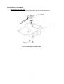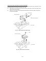
1
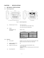
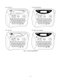
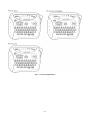
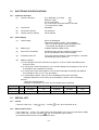
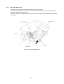
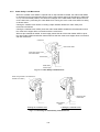
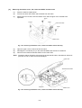
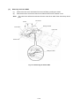
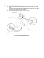
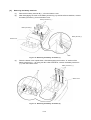
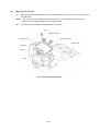
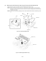
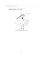
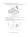
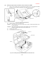
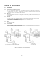
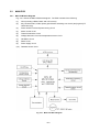
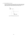
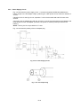
P-touch
SERVICE MANUAL
MODEL: PT-1100/1130/1170/1180/11Q
PT-1250/1160
ST-1150(Heavy Duty LabelerTM)
REVISED 1
SERVICE MANUAL
MODEL: PT-1100/1130/1170/1180/11Q
PT-1250/1160
ST-1150(Heavy Duty LabelerTM)
© Copyright Brother 2002
All rights reserved.
No part of this publication may be reproduced in any
form or by any means without permission in writing
from the publisher.
Specifications are subject to change without notice.
PREFACE
This publication is a service manual covering the specifications, theory of operation,
disassembly/reassembly procedure, and troubleshooting of the Brother PT-1100/1130
/1170/1180/11Q, PT-1250/1160 and ST-1150.
It is intended for service personnel and other concerned persons to accurately and
quickly provide after-sale service for our PT-1100/1130/1170/1180/11Q, PT1250/1160 and ST-1150.
To perform appropriate maintenance so that the machine is always in best condition
for the customer, the service personnel must adequately understand and apply this
manual.
This manual is made up of three chapters and appendices.
CHAPTER I
SPECIFICATIONS
CHAPTER II
MECHANISMS
CHAPTER III
ELECTRONICS
APPENDICES
CIRCUIT DIAGRAMS
CHAPTER I
SPECIFICATIONS
CONTENTS
CHAPTER I SPECIFICATIONS......................................................................... I-1
1.1
1.2
1.3
MECHANICAL SPECIFICATIONS ........................................................................ I-1
1.1.1
External Appearance ...................................................................................... I-1
1.1.2
Keyboard........................................................................................................ I-1
1.1.3
Display ........................................................................................................... I-2
1.1.4
Printing Mechanism........................................................................................ I-2
1.1.5
Tape Cassette ................................................................................................ I-2
1.1.6
Tape Cutter .................................................................................................... I-2
ELECTRONICS SPECIFICATIONS ...................................................................... I-6
1.2.1
Character Generator....................................................................................... I-6
1.2.2
Power Supply ................................................................................................. I-6
SPECIAL KEY....................................................................................................... I-6
1.3.1
Format ........................................................................................................... I-6
1.3.2
Demonstration Print........................................................................................ I-6
CHAPTER I
SPECIFICATIONS
1.1
MECHANICAL SPECIFICATIONS
1.1.1
External Appearance
Fig. 1.1-1 External Appearance
(1)
Dimensions (W x D x H)
154 x 129 x 60 mm
(PT-1100/1130/1170/1180/11Q/ST-1150)
154 x 129 x 64 mm (PT-1250/1160)
(2)
Weight
Machine proper only
In package
Approx. 400 g
Packaging
Weight (g)
Carton with One Unit
670g
Clamshell
650g
Carrying Case
1300g
(including the machine, packing materials and packaged
standard components)
1.1.2
Keyboard
(1)
Entry system
Rubber 41 key (PT-1100/1130/1170/1180/11Q/ST-1150)
Rubber 40 key and tact switch (PT-1250/1160)
(2)
Number of alphanumeric
and symbol keys
30
(3)
Number of function keys
11 (PT-1100/1130/1170/1180/11Q/ST-1150)
10 (PT-1250/1160)
(including On/Off key, L/R pointing keys must be counted
as one.)
(4)
Key arrangement
See Fig. 1.1-2.
I-1
1.1.3
1.1.4
Display
(1)
Display type
Liquid crystal display (LCD)
(2)
Number of columns
8 columns x 1 row (See Fig. 1.1-2.)
(3)
Number of indicators
10 (See Fig. 1.1-2.)
(4)
Character size
5 dots wide by 7 dots high
(5)
Field-of-view angle
adjustment
Fixed by a resistor
Printing Mechanism
(1)
Print method
(2)
Print speed
(3)
Print head
(4)
Thermal transfer onto plastic tapes (laminate tape and
non-laminated tape)
(Fixed print head and tape feeding mechanism)
10 mm/second (Typical)
Type
Thermal print head
Heat generator
Consists of 64 heating elements vertically aligned
Size of heating element
0.195 mm wide by 0.141 mm high
Character size
Ratio
Width x height
Standard (Small) size
(1)
2.26 x 2.96 mm 16 x 21 dot
Double width
(W2)
4.37 x 2.96 mm 31 x 21 dot
Double height
(H2)
2.26 x 5.92 mm 16 x 42 dot
Double width and double height
(4)
4.37 x 5.92 mm 31 x 42 dot
Quadruple width and double height
(8)
8.74 x 5.92 mm 62 x 42 dot
This part explains the dot size of "H" character as an example in the table above, because the
character size is different by the width of the tape and the character.
1.1.5
Tape Cassette
(1)
Cassette
Cartridge type (TZ-cassette)
(2)
Types of tape cassettes
Laminated tape cassette
Non-laminated tape cassette
Cloth tape cassette
(3)
Laminated tape, ink ribbon, and adhesive base tape
Non-laminated tape and ink ribbon
Cloth tape and ink ribbon
Tape size
Laminated tape
Non-laminated tape
Cloth tape
(4)
Width
6, 9, 12 mm
6, 9, 12 mm
12 mm
Length
8m
8m
4m
Tape cassette packed with the machine
Laminated tape cassette containing a 12-mm-wide back ink
ribbon, laminate tape, and adhesive base tape
1.1.6
Tape Cutter
(1)
Tape cutting
Manual cutting with the cutter lever
(2)
Cutter unit
Replaceable by the customer
I-2
Fig. 1.1-2 Key Arrangement (1)
I-3
Fig. 1.1-2 Key Arrangement (2)
I-4
Fig. 1.1-2 Key Arrangement (3)
I-5
1.2
ELECTRONICS SPECIFICATIONS
1.2.1
Character Generator
1.2.2
(1)
Internal characters
U.K./ FRA/ BEL (PT-1250)
205
GER (PT-1250)
213
U.S.A./ CAN./AUS.
176
(PT-1100/1130/1170/1180/11Q/ST-1150,and
PT-1160/1250 for CAN.)
(2)
Internal font
HELSINKI
(3)
Print buffer capacity
55 characters
(4)
Phrase memory capacity
300 characters
Power Supply
(1)
Power supply
Driven by 6 batteries
Optional AC adapter (7VDC, 1.2A) available
* For PT-1180, the power supply is batteries only.
The optional AC adapter is not available.
(2)
Battery type
6 alkaline batteries (AM4/ LR03)
(3)
Service life of batteries
Will last through one tape cassette, and then some.
(at room temperature and normal humidity)
(4)
Automatic power off
Yes (If the machine remains unused for approx. 5 minutes,
it automatically powers itself off.)
(5)
Battery indication
1) If the voltage level of the VAD rises over approx. 10.8V, the CPU immediately shuts
down the power.
2) If it drops even more below approx. 5.3V, the CPU displays the message to warn you of
a low battery after completion of printing.
3) If it drops even more below approx. 5.0V, the CPU interrupts the printing and displays
the message to warn you of a very low battery.
4) If it drops below approx. 4.8V, the CPU immediately shuts down the power.
* Displays different for each country when the battery is weak or when the battery
became
empty are indicated below.
* Displays of specification for U.S.A. and for Canada can be switched.
UK/BELGIUM
FRENCH
GERMAN
U.S.A./AUSTRALIA
CANADA
Battery week
5.3V
BATTERY
B:V
BATTERIE
BATTERY
PILE!
Battery empty
5.0V
BATTERY •
B:V •••••
BATTERIE
BATTERY •
PILE! •••
The underline of eight (8) characters length is drawn for display when the Battery Empty.
1.3
SPECIAL KEY
1.3.1
Format
Push the “Code” key + “BS(
1.3.2
)” key + “On/Off (
)” key, when the power is off.
Demonstration Print
Push “Code” key + “D” key. (PT-1100/1130/1170/1180/11Q/ST-1150, and PT-1160/1250 for CAN.)
Push “Code” key + “D” key+ “On/Off (
)” key. (PT-1250 not only for CAN.)
(It is effective when there is not any data in the text.)
I-6
CHAPTER II
MECHANISMS
CONTENTS
CHAPTER II MECHANISM ................................................................................ II-1
2.1
2.2
THEORY OF OPERATION ................................................................................... II-1
2.1.1
Print Mechanism ............................................................................................ II-1
2.1.2
Platen Roller, (Tape Feed) Sub Roller Setting & Retracting Mechanism ......... II-2
2.1.3
Tape & Ribbon Feed Mechanism.................................................................... II-3
2.1.4
Tape Cutter Mechanism ................................................................................. II-5
2.1.5
Cutter Safety Lock Mechanism....................................................................... II-6
2.1.6
Interlock Mechanism of the Roller Holder ....................................................... II-7
DISASSEMBLY & REASSEMBLY......................................................................... II-8
2.2.1
Disassembly Procedure.................................................................................. II-8
[1]
Removing the cassette cover ASSY, the tape cassette and the batteries..... II-8
[2]
Removing the bottom cover, the cutter case ASSY and the board............... II-9
[3]
Removing the frame ASSY ......................................................................... II-10
[4]
Removing the terminal press cover ............................................................. II-13
[5]
Removing the battery terminals ................................................................... II-14
[6]
Removing the sub PCB ............................................................................... II-15
[7]
Removing the main PCB and the rubber 41 key
(PT-1100/1130/1170/1180/11Q/ST-1150) .................................................... II-16
[8]
Removing the main PCB, the rubber 40 key and the jog dial
(PT-1250/1160) ........................................................................................... II-17
2.2.2
Reassembly Procedure .................................................................................. II-18
[1]
Installing the rubber 41 key and main PCB (PT-1100/1130/1170/1180/11Q/
ST-1150) ..................................................................................................... II-18
[2]
Installing the jog dial, the rubber 40 key and the main PCB
(PT-1250/1160) ........................................................................................... II-19
[3]
Installing the sub PCB ................................................................................. II-20
[4]
Installing the battery terminals ..................................................................... II-21
[5]
Installing the terminal press cover ............................................................... II-21
[6]
Installing the frame ASSY............................................................................ II-22
[7]
Installing the cutter case ASSY, board and the bottom cover....................... II-25
2.3
[8]
Installing the tape cassette, the batteries, and the cassette cover ASSY...... II-26
[9]
Demonstration print and final check............................................................. II-27
TROUBLESHOOTING .......................................................................................... II-33
2.3.1
Precautions .................................................................................................... II-33
2.3.2
After Repairing ............................................................................................... II-33
2.3.3
Error Message Display ................................................................................... II-34
2.3.4
Troubleshooting Flows.................................................................................... II-35
[1]
Tape feeding failure..................................................................................... II-35
[2]
Printing failure ............................................................................................. II-37
[3]
Powering failure (Nothing appears on the LCD) ........................................... II-39
[4]
No key entry possible .................................................................................. II-40
CHAPTER II
MECHANISM
2.1
THEORY OF OPERATION
2.1.1
Print Mechanism
(1)
Structure of Thermal Head
This machine uses thermal transfer printing. The thermal print head has a heat generator
consisting of 64 heating elements which are vertically aligned as shown in Fig. 2.1-1.
Each heating element is 0.195 mm wide by 0.141 mm high.
Fig. 2.1-1 Heat Generator of Thermal Head
(2)
Printing process
When the cylindrical rubber platen roller is pressed against the thermal print head with the
tape* and ink ribbon sandwiched inbetween, the CPU applies electric power to the selected
ones of those 64 heating elements.
* Laminated tape when using laminated tape cassettes.
Non-laminated tape when using non-laminated cassettes.
[For tape cassette except non-laminated thermal film tape cassettes]
If the selected heating element(s) generates heat, the ink on the sandwiched ribbon will be
melted and transferred to the tape, producing a dot(s) on the tape. The ink ribbon and the
tape are advanced and then the next heating cycle is repeated, thus forming a character on
the tape.
[For non-laminated thermal film tape cassettes]
If the selected heating element(s) generates heat, the thermal film tape develops itself to
produce a dot on the tape. The tape is advanced and the next heating cycle is repeated,
thus froming a character on the tape.
(3)
Character Formation
While the drive motor (DC motor) feeds the tape and ink ribbon by 0.141 mm for approx
14.0 ms, the thermal head generates heat once. The feed amount of 0.141 mm is smaller
than the
width (0.195 mm) of the heating elements so that the heat generated at one
heating cycle will overlap with the next heating cycle. This forms a character having no gap
between adjacent printed dots.
II-1
2.1.2
Platen Roller, (Tape Feed) Sub Roller Setting & Retracting Mechanism
This mechanism consists of the holder cam (cassette cover ASSY) and the roller holder ASSY.
The roller holder ASSY supports the platen roller and the sub roller so that :
Ÿ the platen roller can move perpendicularly to the thermal head and rotate freely and
Ÿ the sub roller can move perpendicularly to the tape feed roller and rotate freely.
By closing the cassette cover ASSY, the holder cam of cassette cover ASSY pushes the roller
holder ASSY toward thermal head side by pushing A face of the roller holder ASSY.
The platen roller is pressed perpendicularly against the thermal head with the tape and ink ribbon
(only the tape when using non-laminated thermal film tape cassettes) sandwiched inbetween under
a uniform load by the roller holder springs (upper and lower). Also, the (tape feed) sub roller is
pressed perpendicularly against the tape feed roller built in the tape cassette with the tape (the
laminate tape and adhesive base tape when using laminated tape cassettes) sandwiched
inbetween by the roller holder springs (upper and lower) and at the same time the (tape feed) sub
roller gear becomes engaged with the tape idle gear.
Opening the cassette cover ASSY, (the holder cam of the cassette cover ASSY is released from
the roller holder ASSY), retracts the roller holder ASSY from the thermal head, providing you with
enough space to replace the tape cassette.
Adhesive base tape
Laminate tape
Tape cassette
Platen idle gear
Ink ribbon
Tape feed roller
(Tape feed) sub roller
Thermal head
Shaft
Roller holder ASSY
Holder cam
Platen roller
A
Roller holder lower spring
(Tape feed) platen gear
(Tape feed) sub roller gear
Roller holder release spring
Roller holder upper spring
(Top)
(Tape feed) sub roller
Platen roller
Fig. 2.1-2 Platen and (Tape Feed) Sub Roller Setting & Retracting Mechanism
II-2
2.1.3
Tape & Ribbon Feed Mechanism
This mechanism consists of a DC motor, gear train, and roller holder ASSY.
(1)
Tape Feeding
As the tape feed motor (DC motor) rotates, the rotation is transmitted via the gear train to
the platen idle gear (which rotates both the platen gear) and the tape idle gear (which
rotates the tape feed sub roller).
Accordingly, the sandwiched tape and ink ribbon will be advanced. (When a laminated tape
cassette is mounted, the sandwiched laminate tape, adhesive base tape, and ink ribbon will
be advanced together.)
The feeding amount of the platen is slightly less than that of the tape feed sub roller.
Adhesive base tape
Transparent laminate tape
Platen idle gear
Tape feed roller
(Tape feed) sub roller
Thermal head ASSY
Platen roller
Roller holder ASSY
DC motor
Frame
Tape idle gear
Platen idle gear
Fig. 2.1-3 Tape Feeding Mechanism
II-3
(2)
Adhesive Base Tape Feeding (only for laminated tape cassettes)
A laminated tape cassette contains both a transparent laminate tape roll and a separate
adhesive base tape roll.
When a transparent laminate tape and an adhesive base tape pass through the contact
point (between the tape feed roller and (tape feed) sub roller), they are then bonded together
into a single, printed tape. The ink printed on the laminate tape is, therefore, sealed up with
the adhesive base tape.
(3)
Ink Ribbon Feeding
As the DC motor rotates, the ribbon drive cam located at the middle of the gear train rotates
counterclockwise. When fitted on the ribbon drive cam, the ribbon take-up roll in the tape
cassette also rotates to take up the ink ribbon.
To apply proper tension to the ink ribbon between the platen roller and the ribbon drive cam,
the feed amount of the ribbon drive cam is slightly greater than that of the platen idle gear.
The difference between the tape feed speeds at the platen roller and at the ribbon drive cam
is absorbed by the clutch spring which is integrated in the ribbon drive cam and allows the
cam to slip.
In this way, the ink ribbon is kept tense, which enables the ribbon to clearly separate from
the tape at the stabilized angle after printing.
Tape feed roller
Ink ribbon
(Tape feed) sub roller
Thermal head ASSY
Platen roller
Roller holder ASSY
DC motor
Frame
Ribbon drive cam
Tape idle gear
Platen idle gear
Fig. 2.1-4 Ribbon Feeding Mechanism
II-4
2.1.4
Tape Cutter Mechanism
The tape cut unit consists from the cutter case ASSY and the board.
Tape that finished printing is fed out from the tape cassette and stops at a point passed between
the cutter case ASSY and the board.
When the cutter lever is pushed at this point, then, the cutter case ASSY (cutter blade) is operated
to cut tape.
Tape cassette
Cutter case ASSY
Board
Cutter lever
Cutter blade
Fig. 2.1-5 Tape Cutter Mechanism
II-5
2.1.5
Cutter Safety Lock Mechanism
When the cassette cover ASSY is opened and no tape cassette is loaded, the roller holder ASSY
is retracted from the thermal head with the roller holder release spring (as described in Subsection
2.1.2). In this retracted position, the cutter lever stopper of the roller holder ASSY blocks the end
of the cutter lever, preventing the cutter blade from coming out of the cutter case ASSY for safety,
as shown below.
Closing the cassette cover ASSY or loading a tape cassette release the cutter safety lock
mechanism as follows.
Closing the cassette cover ASSY pivots the roller holder ASSY towards the thermal head so that
the cutter lever stopper does not interfere with the cutter lever.
When a tape cassette is loaded, its outer edge pushes the tab of the roller holder ASSY to pivot
the roller holder ASSY towards the thermal haed so that the cutter lever stopper does not interfere
with the cutter lever.
Cutter lever
Roller holder ASSY
Cutter lever stopper of the
roller holder ASSY
Thermal head
Roller holder
release spring
Fig. 2.1-6 Cutter Safety lock Mechanism
Holder cam (provided on the inside of the
cassette cover ASSY)
Tab of the roller
holder ASSY
Tape cassette
(edge)
Closing the cassette cover
Loading the cassette cover
Fig. 2.1-7 Releasing the Cutter Safety Lock Mechanism
II-6
2.1.6
Interlock Mechanism of the Roller Holder
(1)
When the cassette case ASSY is opened, then the holder cam attached at back side of
cassette cover is released from surface A. Following to that, the roller holder ASSY is
retracted from the thermal head side with tension of the roller release spring.
(2)
When the cassette cover ASSY is closed, then the holder cam located at backside pushes
the thermal head at roller holder ASSY by pressing A surface of the roller holder ASSY.
Thermal head
Platen roller
Tape cassette
(Tape feed)
sub roller
A
Roller holder
release spring
Shaft
Holder cam (Cassette
cover ASSY)
A
Roller holder ASSY
Holder cam (Cassette
cover ASSY)
Thermal head
Tape cassette
Roller holder ASSY
Platen idle gear
Platen roller
Frame ASSY
(Roller Holder ASSY retracted)
(Roller Holder ASSY engaged)
Fig. 2.1-8 Holder Cam (Cassette Cover ASSY) and Roller Holder ASSY
Cassette cover ASSY
Holder cam
Fig. 2.1-9 Interlock Mechanism of the Roller Holder
II-7
PT2002008
2.2
DISASSEMBLY & REASSEMBLY
2.2.1
Disassembly Procedure
[1]
Removing the cassette cover ASSY, the tape cassette and the batteries
(1)
Turn the machine upside down.
(2)
Open the cassette cover ASSY by applying the force toward “A” direction.
(3)
Push the rib “B” on the holder cam assembled on the cassette cover ASSY to the direction
of the arrow to remove the holder cam from the cassette cover ASSY.
Caution: Never draw out the holder cam. The rib “B” on the holder cam may be damaged.
(4)
The cassette cover is removed by applying a force toward “D” direction of the arrow by
pushing the “C” section outward.
(5)
Remove the tape cassette.
(6)
Remove the batteries.
“A”
Holder cam
Cassette cover ASSY
“D”
“B”
“C”
Fig. 2.2-1 Removing the Cassette Cover
Tape cassette
Batteries
Fig. 2.2-2 Removing the Tape Cassette and Batteries
II-8
[2]
Removing the bottom cover, the cutter case ASSY and the board
(1)
Place the machine upside down.
(2)
Pull out the cutter case ASSY and the board from the frame.
(3)
Remove the four screws, then the bottom cover and the upper cover are able to be
separated.
Screw
Screws
Board
Cutter case ASSY
Screw
Bottom cover
Fig. 2.2-3 Removing the Bottom Cover, Cutter Case ASSY and the Board (1)
(4)
Open the upper cover to the left as shown below.
(5)
Discharge the condenser (C1) on the sub PCB ASSY with tool like a screwdriver.
(6)
Disconnect the thermal head flat cable from the main PCB.
Note: Discharge without fail before disconnecting the thermal flat cable, otherwise the electronic
part such as LSI or others should be damaged.
Upper cover
Thermal head flat cable
Sub PCB
Fig. 2.2-4 Removing the Bottom Cover, Cutter Case ASSY and the Board (2)
II-9
Bottom cover
[3]
Removing the frame ASSY
(1)
Remove the two motor harnesses from the sub PCB by melting the solder.
(2)
Remove the three screws and remove the frame ASSY from the bottom cover.
Note:
The cutter lever will be disconnected from the cutter lever shaft of the frame Assy at this
point.
FG harness
Screws
Melting the solder
Frame ASSY
Upper cover
Bottom cover
Melting the solder
Fig. 2.2-5 Removing the Frame ASSY
II-10
Disassembling the Frame ASSY
Removing the DC motor ASSY
(1)
Remove the two screws from the frame ASSY and take out the motor ASSY.
DC motor ASSY
Frame ASSY
Screws
Fig. 2.2-6 Removing the DC Motor ASSY
II-11
Removing the roller holder ASSY and thermal head ASSY
When handling the thermal head ASSY, do not touch the thermal head by hand. Otherwise, it may
be damaged due to the electricity charged in your body.
(1)
After taking off the retaining ring, remove the roller holder ASSY and the roller holder return
spring from the frame ASSY.
(2)
Remove a screw which secures the thermal head ASSY to the frame ASSY, then take out
the thermal head ASSY.
Retaining ring
Roller holder ASSY
Roller holder release spring
Frame ASSY
Fig. 2.2-7 Removing the Roller Holder ASSY
Screw
Thermal head ASSY
Frame ASSY
Fig. 2.2-8 Removing the Thermal Head
II-12
[4]
Removing the terminal press cover
(1)
Remove the terminal press cover by releasing the hooks from the grooves of the bottom
cover.
You can remove the terminal press cover by releasing the two hooks from the back side of
the bottom cover by using tool like a flat screwdriver.
(2)
Remove the battery terminal (-) from the terminal press cover.
Terminal press cover
Battery terminal (-)
Bottom cover
Groove
Hooks
Fig. 2.2-9 Removing the Terminal Press Cover
II-13
[5]
Removing the battery terminals
(1)
Remove the battery terminal B (+,-) from the bottom cover.
(2)
After disengaging the hook of the battery terminal (+) by tool like a flat screwdriver, remove
the battery terminal (+) from the bottom cover.
Battery terminal B (+,-)
Battery terminal (+)
Battery terminal (+)
Bottom cover
Hook
Fig. 2.2-10 Removing the Battery Terminals (1)
(3)
Place the bottom cover upside down. After disengaging the hooks in “A” section of the
battery terminal A (+,-) by using tool like a flat screwdriver, remove the battery terminal A
(+,-) from the bottom cover.
Battery terminal A (+,-)
“A”
Bottom cover
Fig. 2.2-11 Removing the Battery Terminals (2)
II-14
[6]
Removing the sub PCB
(1)
After removing the battery terminal (+), the battery terminal (-), take off a screw and remove
the sub PCB.
Note:
(2)
The AC jack is not provided on the sub PCB for PT-1180. Therefore the form of the
bottom cover is slightly different from the figure below.
The relay harness soldered to the sub PCB is removed.
Screw
Battery terminal (+)
Relay harness
Battery terminal (-)
Bottom cover
Soldering
Sub PCB
AC jack
Fig. 2.2-12 Removing the Sub PCB
II-15
[7]
Removing the main PCB and the rubber 41 key (PT-1100/1130/1170/S1180/11QI-1150)
Remove the four screws, then take off the main PCB and the rubber 41 key.
Note1: Before handling the main PCB, touch a metal portion of the machine to discharge static
electricity, or the LSI and other electronic devices should be damaged due to the electricity
charged in your body.
Note2: The LCD is removed by opening the hook section wide toward direction indicated by arrow
“A”.
Screws
Hook
Screws
Main PCB
“A”
LCD
Rubber 49 key
Upper cover
Fig. 2.2-13 Removing the Main PCB
Rubber 41 key
Upper cover
Fig. 2.2-14 Removing the Rubber 41 Key
II-16
[8]
Removing the main PCB, the rubber 40 key and the jog dial (PT-1250/1160)
Remove the four screws, then take off the main PCB, the rubber 40 key and the jog dial.
Note1: Before handling the main PCB, touch a metal portion of the machine to discharge static
electricity, or the LSI and other electronic devices should be damaged due to the electricity
charged in your body.
Note2: The LCD is removed by opening the hook section wide toward direction indicated by arrow
“A”.
Screws
Hook
Screws
Main PCB
“A”
LCD
Jog dial
Upper cover
Fig. 2.2-15 Removing the Main PCB and the Jog Dial
Rubber 40 key
Upper cover
Fig. 2.2-16 Removing the Rubber 40 Key
II-17
2.2.2
Reassembly Procedure
[1]
Installing the rubber 41 key and main PCB (PT-1100/1130/1170/1180/11Q/ST-1150)
(1)
Turn the upper cover upside down and place the rubber 41 key so that it is fitted into the
nine boss provided on the upper cover.
(2)
Check that there is no foreign material or dust on the key contacts of the main PCB, then
install the PCB. (The LCD is installed first on the upper cover.)
(3)
Tighten the four screws for securing the PCB.
Tightening torque: 0.29 N.m (3 kg.cm)
Screws
Screws
Main PCB
Rubber 41 key
Boss
Upper cover
Fig. 2.2-17 Installing the Rubber 41 Key and Main PCB
II-18
[2]
Installing the jog dial, the rubber 40 key and the main PCB (PT-1250/1160)
(1)
Turn the upper cover upside down and place the rubber 40 key so that it is fitted into the
seven bosses provided on the upper cover.
(2)
The jog dial set on the upper cover.
(3)
Check that there is no foreign material or dust on the key contacts of the main PCB, then
install the PCB. (The LCD is installed first on the upper cover.)
(4)
After matched the jog dial and the main PCB, tighten the four screws for securing the PCB.
Tightening torque: 0.29 N.m (3 kg.cm)
Screws
Screws
Main PCB
Rubber 40 key
Boss
Upper cover
Jog dial
Fig. 2.2-18 Installing the Rubber 40 Key and the Main PCB
II-19
[3]
Installing the sub PCB
(1)
Relay harness is solder connected to the sub PCB.
(2)
After pushing the “A” section of battery terminal (+) of sub PCB ASSY, perform the wiring.
(Refer to Fig. 2.2-20)
(3)
Set the sub PCB into the locating pin and AC jack groove, and tighten the screw, confirming
that each of the sensor switch actuators is fitted into the hole of the bottom cover certainly
and moves up and down freely.
Tightening torque: 0.29 N.m (3 kg.cm)
Note1: Make sure that the battery terminal does not run on the VR1.
Note2: The AC jack is not provided for PT-1180. Therefore the form of the bottom cover is slightly
different from the figure below, and the AC jack groove is also not provided.
Screw
Bottom cover
Main PCB
Relay harness
Sub PCB
AC jack
AC jack groove
Pin
Sensor switch (Actuator)
Fig. 2.2-19 Installing the Sub PCB
Battry terminal (+)
Relay harness
FG harness
VR1
Battery terminal (-)
“A”
Fig. 2.2-20 Details of Battry Terminal (+)
II-20
[4]
Installing the battery terminals
(1)
Put three battery terminals A (+,-) into the bottom cover from the direction of arrow.
(2)
Turn the bottom cover upside down and fit the battery terminal (+) of the battery harness
ASSY into the bottom cover.
(3)
Put two battery terminals B (+,-) into the bottom cover from the same direction.
Note1: When installing the battery terminals, set them into the grooves certainly.
Make sure to fit the all terminals completely.
Note2: Fit the battery terminal (+) firmly at the bottom. Further, make sure that the battery terminal
(+) does not contact with the battery terminals B (+,-).
Battery terminals A (+,-)
Battery terminals B (+,-)
Battery terminal (+)
Bottom cover
Bottom cover
Fig. 2.2-21 Installing the Battery Terminals
[5]
Installing the terminal press cover
(1)
Install the battery terminal (-) to the terminal press cover as shown below.
(2)
Push the terminal press cover along the groove of the bottom cover, until the two hooks are
locked certainly.
Terminal press cover
Battery terminal (-)
Bottom cover
Groove
Fig. 2.2-22 Installing the Terminal Pressure Cover
II-21
[6]
Installing the frame ASSY
(1)
Install the cutter lever into the bottom cover.
(2)
If the frame ASSY has been disassembled, assemble the components by referring to the
next page.
(3)
The frame ASSY is set by matching the locating pin and the locating boss of the bottom
cover.
(4)
The main frame is installed on the bottom cover with 3 screws. The FG harness of sub PCB
Assy is secured to the frame Assy, at this point, with screws of “A”.
Note: Install the frame ASSY so that the FG harness terminal (metallic section) does not contact
with sub PCB.
(5)
Solder the motor harness to the sub PCB.
Note: Be careful to the direction of the motor harness (+), (-) and not to stick out from the
designated place when soldering.
Tightening torque: 0.39 N.m (4 kg.cm)
Screws
FG harness
Frame ASSY
“A”
Motor harnesses
Cutter lever
Locating pin
Sub PCB
Motor harnesses
Soldering
Red
Black
Locating boss
Bottom cover
Soldering
Fig. 2.2-23 Installing the Cutter Lever and the Frame ASSY
II-22
Assembling the components of the motor holder ASSY
Installing the thermal head ASSY and the roller holder ASSY
(1)
Install the thermal head to the frame ASSY, and tighten the screw.
Tightening torque: 0.59 N.m (6 kg.cm)
Screw
Thermal head ASSY
Frame ASSY
Fit for boss
Fig. 2.2-24 Installing the Thermal Head ASSY
(2)
Set the release spring onto the frame ASSY so that its straight end “a” is fitted to the section
“A” on the roller holder ASSY, then install them to the frame so that the spring bent end “b”
becomes hooked on the section “B”. And then set the retaining ring securely.
Roller holder ASSY
Retaining ring
“b”
“a”
“A”
Release spring
“B”
Frame ASSY
Fig. 2.2-25 Installing the Roller Holder ASSY
II-23
Installing the DC motor ASSY
(6)
Tighten the DC motor to the frame ASSY with the two screws. Be careful to the direction of
the motor harnesses.
Tightening torque: 0.10 ∼ 0.20 N.m (1 ∼ 2 kg.cm)
Backlash of DC motor = 0.05 ∼ 0.2 mm
DC motor ASSY
Screws
Fig. 2.2-26 Installing the DC Motor ASSY
II-24
[7]
Installing the cutter case ASSY, board and the bottom cover
(1)
Hold the bottom cover as shown below, then connect the thermal head flat cable to the main
PCB through under the motor harness and the power supply harness connector.
Upper cover
Thermal head flat cable
Bottom cover
Fig. 2.2-27 Installing the Bottom Cover (1)
(2)
Place the upper and bottom cover upside down. And secure the bottom cover by four
screws.
Tightening torque: 0.39 N.m (4 kg.cm)
(3)
The cutter case ASSY and board are inserted into the frame ASSY.
Note: When setting the bottom cover with upper cover, care must be taken so that the cable and
harness are not caught between them.
Screw
Screws
Board
Cutter case ASSY
Screw
Bottom cover
Fig. 2.2-28 Installing the Bottom Cover (2)
II-25
PT2002008
[8]
Installing the tape cassette, the batteries, and the cassette cover ASSY
(1)
Hook “A” of the cassette cover is set at the boss of bottom cover. The cassette is installed,
thereafter, at the “B” section by applying a force (sliding torque) toward “C”.
Cassette cover ASSY
“A”
Boss
“C”
Bottom cover
“B”
Fig. 2.2-29 Installing the Cassette Cover
(2)
Install the holder cam to the cassette cover.
Caution1:
Insert the holder cam into the cassette cover correctly. Check that the holder cam is
not removed easily.
Caution2:
After checking that the “D” section on the cassette cover is not deteriorated or
damaged, install the holder cam into the cassette cover.
(3)
Load the tape cassette.
(4)
Put the batteries in the bottom cover.
“D”
Holder cam
Tape cassette
Batteries
Fig. 2.2-30 Installing the Tape Cassette, the Batteries and the Holder Cam
II-26
[9]
Demonstration Print and Final Check
Following items are verified lastly after completed the assembly.
1.
Press the “On/Off (
2.
While holding down the “Code” key, press the “BS (
entered.
3.
Return the “Caps”, “Size”, “Style”, “UNDL/FRM”, “Function”, and “NUMBER” to the initial
state.
4.
The laminate cassette tape of 12 mm width is installed.
5.
While holding down the “Code” key , press the “D” key (PT-1250/1160: “Code” key + “D” key
+ “On/Off (
)” key) to start the demonstration print.
6.
During the demonstration print, check that the machine feeds the tape and the prints data
correctry. Then cut the tape. (Printing length of the 6mm tape is different from those of the
9/12mm tape.) If any problem is found, go to the trouble shooting in Section 2.3 and 3.3.
7.
Open the casssette cover ASSY to check that it retracts the roller holder ASSY from the
termal head. Thereafter, the cutter safety lock mechanism is verified no problem after
removed the laminate cassette tape.
8.
Remove the batteries, and set the AC adapter (excluding PT-1180). After that, comfirm the
“On/Off (
)” key.
9.
At last, no problem is verified by conducting the following inspections.
9.1.
Inspection Mode Starting Procedure
)” key.
)” key to cancel data previously
)”
The inspection mode is initiated by pressing the “CODE” key, “K” key, and “On/Off (
key simultaneously when internal RAM is cleared while electrical power OFF. (Displays will
become as shown in Fig. 2.) * First, release the “On/Off (
)” key.
However, Error processing will be started when occurred the following error. When such is
the case, please repair by referencing to the Section 2.3 and 3.3 trouble shooting.
9.1.1. Soldering Checks
Checks are performed for the solder points.
Operation is finished by displaying as shown in Fig. 1 when the solder is ON for more than 2
points, or when the soldering made to inappropriate position.
SLDX
Display shown in Fig. 1 appears
only when there is an error at the
solder point.
Fig. 1
9.2.
Modes for Inspection “1” ~ “7” Key
This mode is a mode to perform the final inspection after completed the assembly.
INFO
Fig. 2
9.2.1. Information Mode
Displays as shown in Fig. 2 when entered into the inspection mode, or when depressed “1”
key (excluding when in the key inspection mode).
The information mode performs, by pressing “
display, and the input electrical power checks.
II-27
” key, the country display, head rank
9.2.1.1. Country Display
The country display displays the country specifications as designated by the solder
points (1 ~ 3.)
[UK, GER, FRE, BEL, USA/CAN/AUS]
ROM
Specification
MODEL
Country
Specification
LCD
Display
Solder
Points
1
2
3
US
PT-1100/1130/1170
USA/CAN/AUS
US
H
H
H
PT-1250/1160
CANADA
CA
L
H
H
PT-1250
UK
UK
H
H
H
French
FR
L
H
H
Belgium
BE
H
L
H
German
GE
H
H
H
/1180/11Q/ST-1150
UK
GER
(“L” indicates the soldering.)
9.2.1.2. Head Rank Display
The head rank displays the rank as designated by the solder points (A ~ C).
The rank “B” is defined as the setting for no soldering.
Country Specification
LCD Display
B
0
B
A
C
A
C
Solder Points
A
H
H
L
H
B
C
H
H
L
H
H
H
H
L
(“L” indicates the soldering.)
9.2.1.3. Power Supply Voltage Check Display (Inspection voltage: 7.5 ± 0.2 V)
Displays “
” when within the required input voltage range.
Displays “ X ” when out of the range.
Country
Specification
Voltage Display
US
0
Country Display: USA/CAN/AUS
Head Rank Display: B rank
Voltage Display: No problem
Head Rank
Fig. 3 An Example of INFO Mode Display
II-28
9.2.1.4. LCD Check Display
Here, check for missing dots and the display function of the LCD.
The LCD check 1 <Fig. 4> is displayed when depressed “
HHHHHHHH
” key.
All guidance off.
All cursor off.
Fig. 4
The LCD check 2 <Fig. 5> is displayed when depressed “
XXXXXXXX
” key.
All guidance on.
All cursor on.
Fig. 5
Shifts to “28.2.2 Cassette Inspection Mode” when depressed “
X
” key. (Fig. 7 Display)
All guidance on.
All cursor on.
Fig. 6
9.2.2. Cassette Sensor Inspection Mode “2” Key
Here, ckeck the cassette sensor function.
Display of Fig. 7 is indicated when depressed “
” key or depressed “2” key in the display
of Fig. 6 (except while in the Key Inspection Mode).
CAST
Fig. 7
Shifts to the Key Inspection Mode when depressed “
CAS
” key. (Fig. 8 Display)
000
Fig. 8
Displays the three sensor SW states. ON: 1, OFF: 0
Touch the sensor switch with the finger tip while checking ON/OFF display.
Shifts to the Key Inspection Mode when depressed “
” key. (Fig. 9 Display)
9.2.3. Key Inspection Mode “3” Key
Here, check the key input function.
Display of Fig. 9 is indicated when depressed “
” key or depressed “3” key in the display
of Fig. 8 (except while in the Key Inspection Mode).
KEY
Fig. 9
Shifts to the Key Inspection Mode when depressed “
” key. (Fig. 10 Display)
The “CODE” key, “(
)” key”, “BS(
)”, “←”, “→” key (1st row) L → R, (2st row) R → L,
(3st row) L → R, 4st row) R → L, (5st row) L → R are depressed sequentially. The key to
depress is displayed (refer to Fig. 10) and the key to depress next is displayed when
depressed correctly while the key to depress next and “X” are displayed when depressed
erroneously. (Fig. 11 Display)
II-29
A
Fig. 10
S
X
Fig. 11
When all key checks were completed, then displays Fig. 12 and cut the tape by printing
<<OK>>.
OK
Fig. 12
Shifts to “9.2.4 CUT Mode” when depressed “
” key. (Fig. 14 Display)
* PT-1250/1160, however, shifts to the “JOG Dial Check Mode”.
Enters into the JOG Dial Check Mode after printed that all key had been completed without
displaying OK. The cursor moves toward direction of the rotation.
After confirmation was made, shifts to “9.2.4 CUT Mode” when depressed “
13 Display)
” key. (Fig.
JOG?
Fig. 13
9.2.4. Cut Mode “4” Key
Here, check the cutter function.
Display of Fig. 12 is indicated when depressed “
” key or depressed “4” key in the display
of Fig. 13 (except while in the Key Inspection Mode).
CUT
Fig. 14
Fig. 15 is displayed when depressed “
completed the feed.
FEED
” key to feed the tape. “1“ is displayed after
1
Fig. 15
Fig. 16 is displayed when depressed “
completed the feed.
FEED
2
Fig. 16
II-30
” key to feed the tape. “2” is displayed after
Fig. 17 is displayed when depressed “
completed the feed.
” key to feed the tape. “3” is displayed after
FEED
3
Fig. 17
Shifts to “28.2.5 PRINT 1 Mode” when depressed “
” key. (Fig. 18 Display)
9.2.5. PRINT 1 Mode “5” Key
Here, check the print quality, tape length accuracy and print length accuracy.
Display of Fig. 18 is indicated when depressed “
” key or depressed “5” key in the display
of Fig. 17 (except while in the Key Inspection Mode).
PRN1
Fig. 18
The printing is started when depressed “
” key. (Fig. 18 Display)
Initialize all memory after completed the printing and turns the electrical power to off.
<A Printing Sample>
After finishing to print, cut the printed tape and check that it is 79 ± 4 mm (tape length) and
50.2 +4, -2.5 mm (printed letter length)
9.2.6. PRINT 2 Mode “6” Key
Performs the same printing as PRINT 1.
My be omitted when PRINT 1 is confirmed being correct.
Fig. 19 is displayed when depressed “6” key (except while in the Key Inspection Mode).
PRN2
Fig. 19
The function is started when depressed “
off in this case.
II-31
” key. The electrical power will not be turned to
9.2.7. MOTOR Mode “7” Key: Used for the DC motor speed adjustment.
This mode is used only when the print length accuracy or tape feed length accuracy
deviates from the specification.
Display of Fig. 20 is indicated when depressed “7” key.
MTR
Fig. 20
The function (MOTOR rotation) is started when depressed “
” key. The electrical power
will not be turned to off in this case. The “On/Off (
)” key is depressed to stop.
When you failed, peel off the yellow “+” volume (VR1) by the cassette sensor switch
actuators as shown below. And insert a screwdriver to adjust the length of the tape by
rotating a trimmer.
If rotating the trimmer to the right (CW), the length becomens short.
If rotating to the left (CCW), it becomes long.
After the adjustment, verify the tape length and printed letter length by performing the
PRINT 1 or PRINT 2 functions.
Yellow “+” volume (VR1)
Bottom cover
Fig. 21
10
This machine becomes formatted, if you discharge the electricity after removing the AC
adapter and the batterries. (Refer to Format in the 1.3.1)
II-32
2.3
TROUBLESHOOTING
This section gives the service personnel some of the troubleshooting procedures to be followed if
an error or malfunction occurs with the PT-1100/1130/1170/1180/11Q, PT-1250/1160 and ST1150. It is impossible to anticipate all of the possible troubles which may occur in future and
determine the troubleshooting procedures, so this chapter covers some sample troubles.
However, those samples will help service personnel pinpoint and repair other defective elements if
he/she analyzes and examines them well.
2.3.1
Precautions
Be sure to observe the following precautions to prevent the secondary problems from happening
during troubleshooting:
2.3.2
(1)
Get a good idea of what the trouble is. Whenever more than one trouble source is found,
plan the most reasonable repairing procedure after reviewing the relationship between them.
(2)
When supplying power to the PT-1100/1130/1170/1180/11Q, PT-1250/1160 and ST-1150
having problems from either a set of batteries or the AC adapter (excluding PT-1180), make
sure that its output voltage level is 8 to 10V under no load.
(3)
When supplying power from a stabilized power unit, use the power unit with approx.
3A capacity and choose the output level of 7 to 10V. When connecting it to the PT1100/1130/1170/1180/11Q, PT-1250/1160 and ST-1150, be careful with the polarity.
(4)
When using a circuit tester for testing the conductivity, remove all of the batteries and the
AC adapter (models except PT-1180) from the PT-1100/1130/1170/1180/11Q, PT1250/1160 and ST-1150.
(5)
To repair an error which occurred in the thermal print head and its related sections,
disconnect the thermal head cable until repairs are finished.
After Repairing
After troubleshooting, be sure to check the failure to make sure that the failure has been
completely remedied. Note and keep the troubleshooting procedure actually followed for later
troubleshooting.
II-33
2.3.3
Error Message Display
Error is displayed when the troubles as shown below happen.“ERROR” display for each country
will be displayed as follows.
U.S.A./U.K./BELGIUM: ERROR
FRENCH/CANADA: ERREUR
GERMAN: FEHLER
Input Mode
Text Input Mode
Dead Letter Input
Mode
Function Selection
Mode
Number of Copy
Setting Mode
Final Numbering Value
Setting Mode
Memory Selection
Mode
File Display Mode
Error Conditions
“SET (
)” key depressed when
exceeded 2. lines
“PRINT” key depressed when no
data in the text buffer.
“PRINT” key depressed when no
cassette installed.
“PRINT” key depressed when text
vertical size is larger than the
installed tape width.
“PRINT” key depressed when 2
line-print 6 mm tape installed.
“FEED” key depressed when no
cassette installed.
“SET (
)” key depressed when
exceeded 2 lines
“SET (
)” key depressed when
selected repeat or numbering while
no data in the text buffer.
“SET (
)” key depressed when
no letter on the cursor or when tried
numbering while no numeral on the
cursor.
“SET (
)” key depressed when
no cassette installed.
“SET (
)” key depressed when
text vertical size is larger than the
installed tape width.
“SET (
)” key depressed when 2
line-print 6 mm tape installed.
“SET (
)” key depressed when
no cassette installed.
“SET (
)” key depressed when
text vertical size is larger than the
installed tape width.
“SET (
)” key depressed when 2
line-print 6 mm tape installed.
“SET (
)” key depressed when
the selected final value is smaller
than those subject to numbering.
“SET (
)” key depressed when
tried to register to memory while no
data in the text buffer.
“SET (
)” key depressed when
tried to call-out to memory while no
file registered.
“SET (
)” key depressed when
tried to call-out the file with no
data.
II-34
Remarks
French: “Impr” key/German “Druck”
key.
French: “Impr” key/German “Druck”
key.
French: “Impr” key/German “Druck”
key.
French: “Impr” key/German “Druck”
key.
French: “Avance” key/German “BV”
key.
Resumes to the previous mode
after erased the message.
Resumes to the previous mode
after erased the message.
2.3.4
Troubleshooting Flows
[1]
Tape feeding failure
II-35
II-36
[2]
Printing failure
II-37
II-38
[3]
Powering failure (Nothing appears on the LCD)
II-39
[4]
No key entry possible
II-40
CHAPTER III
ELECTRONICS
CONTENTS
CHAPTER III ELECTRONICS ........................................................................... III-1
3.1
3.2
OVERVIEW .......................................................................................................... III-1
3.1.1
Configuration of the Electronic Part ................................................................ III-1
3.1.2
Main PCB....................................................................................................... III-1
3.1.3
Sub PCB ........................................................................................................ III-1
3.1.4
Motor.............................................................................................................. III-1
3.1.5
Thermal Head ................................................................................................ III-1
MAIN PCB............................................................................................................. III-2
3.2.1
Main PCB Block Diagram ............................................................................... III-2
3.2.2
CPU and LCD Driver ...................................................................................... III-3
3.2.3
Key Contacts Matrix ....................................................................................... III-4
[1]
Key contacts matrix ..................................................................................... III-4
[2]
Solder points ............................................................................................... III-5
[3]
Jog Dial (Only for PT-1250/1160) ................................................................ III-6
3.2.4
On/Off Key/Reset Circuit and Power Saving Circuit........................................ III-7
[1]
Power On/Off circuit .................................................................................... III-7
[2]
Power saving circuit .................................................................................... III-8
3.2.5
Motor Control Circuit ...................................................................................... III-9
3.2.6
Thermal Head Drive Circuit ............................................................................ III-10
3.2.7
Voltage Detection Circuit and Temperature Sensor circuit .............................. III-11
[1]
Voltage detection circuit .............................................................................. III-11
[2]
Ambient temperature sensor circuit ............................................................. III-12
3.2.8
Oscillation Circuit ........................................................................................... III-13
3.2.9
Power Supply Circuit ...................................................................................... III-14
3.2.10 Cassette Sensor Circuit .................................................................................. III-15
3.3
TROUBLESHOOTING .......................................................................................... III-16
3.3.1
Precautions .................................................................................................... III-16
3.3.2
After Repairing ............................................................................................... III-16
3.3.3
Troubleshooting Flows.................................................................................... III-17
[1]
Tape feeding failure..................................................................................... III-17
[2]
Printing failure ............................................................................................. III-17
[3]
Powering failure (Nothing appears on the LCD.) .......................................... III-18
[4]
Abnormal LCD indication............................................................................. III-19
[5]
No key entry possible .................................................................................. III-20
[6]
Tape cassette type not identified ................................................................. III-20
CHAPTER III
ELECTRONICS
3.1
OVERVIEW
3.1.1
Configuration of the Electronic Part
Fig. 3.1-1 shows a block diagram of the control electronics of the PT-1100/1130/1170/1180/11Q,
PT-1250/1160 and ST-1150. The control electronics consists of a printed circuit board (main PCB
+ Sub PCB), a motor, and a thermal head assembly.
3.1.2
Main PCB
This manages all the components including an LCD, keyboard, (Jog dial :PT-1250/1160 only) and
thermal head.
3.1.3
Sub PCB
Sub PCB consists of the sensor switches which identify the tape cassette type, governor circuit
which controls the rotation of DC motor, AC adapter jack and battery terminal.
(The AC jack is not provided for PT-1180.)
3.1.4
Motor
DC motor feeds tape.
3.1.5
Thermal Head
This is a thick film thermal print head which integrates a heat generator (consisting of 64 heating
elements vertically aligned) and drive circuit.
(PT-1100/1130/1170/1180/11Q/ST-1150)
(PT-1250/1160)
Fig. 3.1-1 Configuration of the Electronic Part
III-1
3.2
MAIN PCB
3.2.1
Main PCB Block Diagram
Fig. 3.2-1 shows the Main PCB block diagram. The PCB consists of the following:
(1)
CPU (including a ROM, RAM, and LCD control)
(2)
Key contacts matrix, solder points (specification switching-over circuit) and jog dial (PT1250/1160 only).
(3)
Power On/Off circuit and power saving circuit
(4)
Motor control circuit
(5)
Thermal head drive circuit
(6)
Voltage detection circuit and temperature sensor circuit
(7)
Oscillation circuit
(8)
Reset circuit
(9)
Power supply circuit
(10)
Cassette sensor circuit
Fig. 3.2-1 Main PCB Block Diagram
III-2
3.2.2
CPU and LCD Driver
The CPU (MU101C30A) is a 8bit microprocessor produced by CMOS silicon gate process, which
integrates a 32 kilobyte-ROM and a 1.5 kilobyte-RAM.
The LCD driver (SPLC 780 A2) is a LSI that drives the LCD in 1/8 duty and 1/4 bias level.
Fig. 3.2-2 CPU, CG ROM and LCD Drive
III-3
3.2.3
Key Contacts Matrix
[1]
Key contacts matrix
On the main PCB is a key contacts matrix that is a set of carbon-printed 41 key (PT-1250/1160: 40
key + tact switch) contact patterns. Each contact pattern has a pair of electrodes.
The rubber 42 key (PT-1250/1160: 41 key) is made of high-impedance silicon rubber. As shown in
Fig. 3.2-3, each key on the rubber 42 key (PT-1250/1160: 41 key) consists of a key top, rubber
spring, and conductive paint which functions as a switching element.
If a particular key is pressed, the conductive paint of the key short-circuits the paired electrodes
carbon-printed on the main PCB.
Fig. 3.2-4 shows a timing chart and waveforms of key scanning by the CPU. Ports P71 through
P76 on the CPU produce a series of key scanning pulses. Every scanning pulse is in low
impedance for 1 ms while active and in high impedance while inactive. Ports P60 through P67 act
as input ports which receive key status.
The CPU scans the key contacts matrix every 10 ms. If the CPU reads the same data on an input
port two successive times, it interprets the state as the key being pressed; if the CPU reads the
same data six successive times, it interprets the state as the key being released. The input mode
of this keying system is 2-key roll-over and 3-key lock-out.
Key top
Rubber spring
Conductive paint
Electrodes
Main PCB
Fig. 3.2-3 Detailed Mechanism of a Key
Fig. 3.2-4 Timing Chart and Waveforms of Key Scanning by the CPU
III-4
[2]
Solder points
Fig. 3.2-5 shows a circuit diagram relating to the keyboard and solder points. Solder points 1
through 4 are connected to satisfy the specification of PT-1100/1130/1170/1180/11Q, PT1250/1160 and ST-1150.
Specification
PT-1250
Solder point
No point solder
MN101C30ABE
UK
Point 1 solder
Point 2 solder
French
Belgium
PT-1160
MN101C30ABF1
German
PT-1100/1130/1170/1180
11Q/ST-1150
MN101C30ABD
U.S.A., Canada,
Australia
Canada
Solder points A through D are reserved for the future use for the thermal head ranking.
The CPU reads the solder point status once in the powering-on to confirm the specification.
III-5
[3]
Jog dial (Only for PT-1250/1160)
The two input signal (JOG0, JOG1) waveforms are varied by rotating the JOG dial. The rotational
directions are determined from the variation pattern of this two input signal waveforms.
<JOG Switching Dial Signal>
(CW)
JOG0 signal
JOG1 signal
(CCW)
JOG0 signal
JOG1 signal
Fig. 3.2-6
Fig. 3.2-7 Jog Dial Circuit
III-6
3.2.4
On/Off Key/Reset Circuit and Power Saving Circuit
[1]
Power On/Off circuit
Fig. 3.2-8 shows a circuit diagram of the power On/Off key. The CPU processes the On/Off key
state in a sequence quite different from other keys although the On/Off key is on the same key
pad.
Fig. 3.2-8 On/Off Key Circuit
Fig. 3.2-9 Powering-On/Off sequence
III-7
[2]
Power saving circuit
Fig. 3.2-10 shows a circuit diagram of the power saving circuit. If you power off the machine with
the power On/Off key or you make no key entry for approx. 5 minutes, the CPU turns P11 high to
cut off the Vcc (which normally would feed power to the logic circuits except the CPU). In this
way, the CPU enters the sleep mode where oscillation stops so as to feed no clock to the CPU.
In the sleep mode, the +5BV feeds power only to the CPU.
To cancel the power saving mode (automatic powering-off mode) and resume the normal
operation mode, press the power On/Off key.
Fig. 3.2-10 Power Saving Circuit
III-8
3.2.5
Motor Control Circuit
Fig. 3.2-11 shows the motor drive control of the DC motor which feeds tape.
Through P10, the CPU produces a start/stop control signal to the motor control circuit. Fig. 3.2-12
shows the part of motor waveforms.
#1 (BA6220) is electronic governor IC and controls to keep the rotation speed of motor constant
even if the power source voltage (VBT) varies.
Fig. 3.2-11 Motor Control Circuit
Fig. 3.2-12 Part of Motor Waveforms
III-9
3.2.6
Thermal Head Drive Circuit
Fig. 3.2-13 shows the thermal head drive circuit.
The print head used in the integrates a heat generator (consisting of 64 heating elements vertically
aligned in 180 dpi) and a built-in driver IC.
Synchronizing with the clock on P02, the CPU outputs print data on P00 in the serial waveform.
Upon receipt of P01 signal produced by the CPU, the thermal head control circuit latches the print
data and drivers the heating elements of the thermal head according to the signal produced from
P03. Fig. 3.2-14 shows the timing chart of the thermal head drive.
Capacitor C12 works as a thermal head overheat protector. It cuts off the P03 signal to shut down
invalid drive current if the signal sticks to the low level due to any malfunctions of the programs or
the CPU.
Since the thermal head is very sensitive to heat and the head drive source is not stabilized, the
CPU determines the ON-time length of the P03 signal while monitoring the head drive source
voltage and the ambient temperature (refer to Subsection 3.2.7).
Fig. 3.2-13 Thermal Head Drive Circuit
Fig. 3.2-14 Timing Chart of Thermal Head Drive
III-10
3.2.7
Voltage Detection Circuit and Temperature Sensor circuit
Fig. 3.2-15 and Fig. 3.2-16 (See next page) show the voltage detection circuit and the ambient
sensor circuit which are composed of a resister combination.
[1]
Voltage detection circuit
This circuit, which is composed of divider resistors R8 and R10, steps down the power source VAD
fed from batteries or the AC adapter output and feeds the output to the A/D input port PA1 on the
CPU. According to the drive source voltage, the CPU determines the optimum head drive power.
During non-printing:
If the voltage level of the VAD drops below approx. 6.8V, the CPU immediately shuts down the
power.
During printing:
• If the voltage level of the VAD rises over approx. 10.8V, the CPU immediately shuts down the
power.
• If it drops even more below approx. 5.3V, the CPU displays the message to warn you of a low
battery after completion of printing.
• If it drops even more below approx. 5.0V, the CPU interrupts the printing and displays the
message to warn you of a very low battery.
• If it drops below approx. 4.8V, the CPU immediately shuts down the power.
Fig. 3.2-15 Voltage Detection Circuit
III-11
[2]
Ambient temperature sensor circuit
This circuit is composed of resistors R12 and a thermistor TH2. It converts the resistance of the
TH2 (whose internal resistance varies depending upon the ambient temperature) to the voltage
variation, and then feeds its output to the A/D input port PA0 on the CPU. According to the
Ambient temperature data, the CPU determines the optimum head drive power.
Fig. 3.2-16 Ambient Temperature Sensor Circuit
III-12
3.2.8
Oscillation Circuit
Fig. 3.2-17 shows the oscillation circuit.
This circuit contains an oscillator and generates an oscillation at 8 MHz which act as the CPU
basic clock. The CPU divides this into half (4 MHz) to synchronize its internal operations.
Fig. 3.2-17 Oscillation Circuit
III-13
3.2.9
Power Supply Circuit
Fig. 3.2-18 shows the power supply circuit. A 3-terminal regulator RH5RL50A stabilizes the
battery output or the AC adapter output, producing the +5BV power source within the variation of
±0.15V.
Capacitor C4 is for the logic circuit; capacitor C1 is for the thermal head and DC motor drive
sources.
Connecting the AC adapter plug with the AC jack J1 cuts off the power fed from the batteries and
feeds power from the AC adapter. (However, the power for memory backup is fed from the
battery.)
Note1: The AC jack is not provided for PT-1180.
Fig. 3.2-19 shows the polarity of the AC adapter plug.
Fig. 3.2-18 Power Supply Circuit
Fig. 3.2-19 AC Adapter Plug
III-14
3.2.10 Cassette Sensor Circuit
Fig. 3.2-20 shows the cassette sensor circuit. This circuit detects each of the five sensor switches
which is pushed or not depending upon the ID holes provided on a tape cassette currently
mounted.
By perceiving the states of those sensor switches, the CPU identifies the tape cassette type (the
varieties and the widths).
If an ID hole is open, the sensor switch is not pushed.
Table 3.2-1 lists the coded values for identifying the tape cassette type.
Fig. 3.2-20 Cassette Sensor Circuit
Table 3.2-1 Coded Values for Identifying Tape Cassette Type
III-15
3.3
TROUBLESHOOTING
This section gives the service personnel some of the troubleshooting procedures to be followed if
an error or malfunction occurs with the PT-1100/1130/1170/1180/11Q, PT-1250/1160 and ST1150. It is impossible to anticipate all of the possible troubles which may occur in future and
determine the troubleshooting procedures, so this chapter covers some sample troubles.
However, those samples will help service personnel pinpoint and repair other defective elements if
he/she analyzes and examines them well.
3.3.1
Precautions
Be sure to observe the following precautions to prevent the secondary problems from happening
during troubleshooting:
(1)
Get a good idea of what the trouble is. Whenever more than one trouble source is found,
plan the most reasonable repairing procedure after reviewing the relationship between them.
(2)
When supplying power to the PT-1100/1130/1170/1180/11Q, PT-1250/1160 and ST-1150
having problems from either a set of batteries or the AC adapter, make sure that its output
voltage level is 8 to 10V under no load.
(3)
When supplying power from a stabilized power unit, use the power unit with approx. 3A
capacity and choose the output level of 7 to 9V.
When connecting it to the PT-1100/1130/1170/1180/11Q, PT-1250/1160 and ST-1150, be
careful with the polarity.
3.3.2
(4)
When using a circuit tester for testing the conductivity, remove all of the batteries and the
AC adapter from the PT-1100/1130/1170/1180/11Q, PT-1250/1160 and ST-1150.
(5)
To repair an error which occurred in the thermal head and its related sections, disconnect
the thermal head cable until repairs are finished.
After Repairing
After troubleshooting, be sure to check the failure to make sure that the failure has been
completely remedied. Note and keep the troubleshooting procedure acturally followed for later
troubleshooting.
III-16
3.3.3
Troubleshooting Flows
[1]
Tape feeding failure
[2]
Printing failure
III-17
[3]
Powering failure (Nothing appears on the LCD.)
III-18
[4]
Abnormal LCD indication
III-19
[5]
No key entry possible
[6]
Tape cassette type not identified
III-20
APPENDICES
Circuit Diagrams
A: MAIN PCB CIR 1100
(PT-1100/1130/1170/1180/11Q/ST-1150)
B: MAIN PCB CIR 1250
(PT-1250/1160)
C: SUB PCB CIR 1250
Jan., 2002
8V2010BE1
Printed in Japan