1
OWNERS
MANUAL
MODE L NO,
917_255741
Caution:
Read Rules for
Safe Operation
and Instructions
Carefully
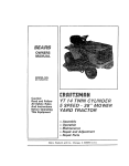
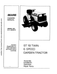
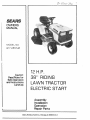
12 H.P.
38" RIDING
LAWN TRAC TOR
ELECTRIC START
Assembly
Installation
Operation
Repair Parts
Sears, Roebuck and Co,, Chicago, tL 60684 US A,
CONGRATULATIONS
Tractor
It has been
on your purchase
designed,
engineered
of a Sears Lawn
and manufactured
MODE L
NUMBER
SERIAL
NUMBER
to give you the best possible dependability
and performance.
Should you experience
any problem
you cannot easily remedy, please contact
your nearest
Sears Service
DepartmenL
They have competent,
well-trained
technicians
and the proper
tools to service or repair this unit.
THE MODEL AND SERIAL NUMBERS WILL BE
FOUND ON THE MODEL PLATE ATTACHED TO
THE FENDER_
Please read and retain this manual, The instructions
will enable
you to assemble, operate and maintain
your TractoF properly.
Always observe the "RULES
FOR SAFE OPERATION"
YOU SHOULD
RECORD
BOTH MODEL AND
SERIAL NUMBERS AND KEEP IN A SAFE PLACE
FOR FUTURE REFERENCE
LIMITED
TWO YEAR WARRANTY
ELECTRIC
START RIDING
EOUIPMENT
ON
For two years from date of purchase, when this riding equipment is maintained, lubricated, and
tuned up according to the operating and maintenance instructions
in the owner's manual, Sears
will repair free of charge any defect in material or workmanship
in this electric start riding equipment.
'This warranty excludes blade(s), blade adapter(s),
expendable and become worn during normal use.
spark plug(s), air cleaner(s) and belt(s), which are
This warranty does not cover:
tire replacement or repair caused by punctures from outside objects (such as nails, thorns,
stumps, or glass); and
repairs necessary because of operator abuse or negligence, including the failure to maintain the equipment according to instructions contained in the owner's manual; and
riding equipment used for commercial or' rental purposes_
FULL
90-DAY
WARRANTY
ON
BATTERY
For 90 days from the date of purchase, if any battery included with this riding equipment proves
defective in material or' workmanship and our testing determines the battery wilt not hold a charge,
Sears will replace the battery at no charge,
WARRANTY
SERVICE IS AVAILABLE
BY CONTACTING
THE NEAREST SEARS SERVICE
CENTER/DEPARTMENT
IN THE UNITED
STATES., This warranty
applies only while this
product is in use in the United States,
This warranty gives you specific
state to state_
legal rights, and you may also have other
rights which vary from
.Sears,Roebuck and Co., D/698-731A, Sears Tower, Chicago, IL 60684
TABLE OF CONTENTS
RULES FOR SAFE OPERATION
ASSEMBLY
INSTRUCTIONS
................
....................
OPERATION
INSTRUCTIONS
o TRACTOR
OPERATION
INSTRUCTIONS-
MOWER
.......
.......
3
MAINTENANCE
INSTRUCTIONS
-MOWER .....
12
4
MAINTENANCE
INSTRUCTIONS-
TRACTOR.
_14
8
TROUBLE
11.2-
REPAIR
SHOOTING
......................
PARTS ............................
21
24
FOR SAFE
OPERAT O
NARNING:
This unit is equipped
with an internal combustion
engine and should not be used on or near any unimproved
forestcovere6, brush,covered
or grass-covered land unless the engine's exhaust system is equipped
with a spark arrestor meeting applicable
Local or statelaws(if
any) Ifasparkarrester
is used. it should be maintained
in effective
working
order by the operator
tn the State of California
the above is required
by Iaw (Section
4442 of the California
Public Resources
Code) Other states may
have similar
laws
Federal iaws apply on federat lands. See your Sears Authorized
Service Center for spark arrester muffler
part
number 677V1
23
Use care when pulling loads or using heawyequipment,
a_ Use only approved drawbar hitch points
b Limit loads to those you can safely control
co Do not turn sharply Use care when backing
do Use count_erweight or wheel weights when suggested in
the owner s manual.
24 Watch out for traffic when crossing or near roadways
25 When using any attachments, never direct discharge of
material toward bystanders nor allow anyone near the vehicle while in operation
26 Handle gasoline with care it is highly flammable
a, Use approved gasoline containers
b, Never remove the fuel cap of the fuel tank or add gasoline to a running or hot engine or an engine that has
not been allowed to cool for several minutes after running, Never fill the tank indoors, always clean up spilled
gasoline
c. Open doors if the engine is run in the garage - exhaust
fumes are dangerous. Do not run the engine indoors.
27, Keep the vehicle and attachments in good operating condition, and keep safety devices in place and working.
28. Keep al! nuts, bolts and screws tight to be sure the equip=
ment is in safe working condition
29 Never store the equipment with gasoline in the tank inside
a building where fumes may reach an open flame or spark.
Allow the engine to cool before storing in any enclosure.
30 To reduce fire hazard, keep the engine free of grass, leaves
or excessive grease Do not clean product while engine is
running
31, Except for adjustment; DO NOT operate Engine if air
cleaner or cover directly over carburetor air intake is re=
moved Removal of such part could create a fire hazard
32 Do not operate without a muffler or tamper with the
exhaust system. Damaged mufflers or spark arrestors could
create a fire hazar& Inspect periodically and replace if
necessary.
33 The vehicle and attachments should be stopped and inspected for damage after striking a foreign object and the
damage should be repaired before restarting and operating
the equipment
34 Do not change the engine governor settings or overspeed
the engine; severedamage or injury may result
35_ When using the vehicle with mower, proceed as follows:
a. Mow only in daylight or in good artificial light
b. Shut the engine off when unclogging chute°
c. Check the blade mounting bolts for proper tightness at
frequent intervals.
36. Do not operate the mower without the deflector shield in
place
37. Disengage power to mower before backing up Do not mow
in reverse unless absolutely necessary and then only after
careful observation of the entire area behind the mower
38 Under normal usage the grass catcher bag materiaf is subject
to deterioration and wear It should be checked frequently
for bag replacement Replacement bags should be checked
to ensure compliance with the original manufacturer's
recommendations or specifications
1.. Know the controls and how to stop quickly, READ THIS
OPERATOR'S
MANUAL
and instructions
furnished
with attachments
2. Do not allow children to operate the machine. Do not
allow adults to operate it without proper instruction.,
3, Do not carry passengers.. Do not mow when children and
others are around,
4. AIways wear substantial footwear. Do not wear loose fitting
clothing that could get caught in moving parts..
5o Keep your eyes an_ mind on your tractor, mower and the
area being cut.. Don t let other interests distract you°
6. Do not attempt to operate your tractor or mower when
not in the drivers seat.
7. Always get on or off your tractor from the operators left
hand side,.
8, Clear the work area of obiects (wire, rocks, etc_) which
might be picked up and thrown,
9o Disengage all attachment clutches before attempting to
start the engine,
10. Disengage power to att{chments and stop the engine before leaving the operator s position
tio Disengage power to mower, stop the engine and disconnect
spark plug wire(s) from spark plug(s) before cleaning, making an adjustment or repairs
12 Disengage power to attachments when transporting or not
in use.
13, Take all possible precautions when leaving the vehicle unattended. Disengage the power4ake-off, lower the attachmerits, shift into neutral, set the parking brake, stop the
engine and remove the key°
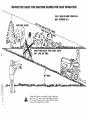
14 Do not stop or start suddenly when going uphill or down• hill Mow up and down the face of slopes (not greater than
15°); never across the face Refer to page 43
15o Reduce speed on slopes and make turns gradually to prevent tipping or loss of control Exercise extreme caution
when changing direction on slopes.
16o While going up or down slopes, place Gear Shift Control
Lever in 1st gear position to negotiate the slope without
stopping
17o Never mow in wet or slippery grass, when traction is unsure or at a speed which could causea skid
!8 Stay alert for holes in the terrain and other hidden hazards
Keep away from drop offs,
19o Do not drive too close to creeks, ditches and public highways°
20, Exercise special care when mowing around fixed objects
in order to prevent the blades from striking them Never
deliberately run tractor or mower into or over any foreign
object,
21_ Never shift gears until tractor comes to a stop°
22° Never place hands or feet under the mower, in discharge
chute or near any moving parts while tractor or mower are
running. Always keep clear of discharge chute,
PRECAUTIONS,
MEANS TO
- POINT
ATTENTION!
BECOME ALERTI
LOOK FOR THIS IT
SYMBOL
OUT IMPORTANT
SAFETY
YOUR SAFETY IS INVOLVED
*3
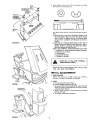
To assemble your Tractor you will need:
two 7/16"
wrenches, two 9/16" wrenches, two
1/2" wrenches, a 3/4" wrench and a utility knife
NOTE: RIGHT HAND (R,H) AND LEFT HAND (LH.) ARE
DETERMINED
FROM OPERATOR'S
POSITION WHILE
SEATED ON THE TRACTOR
ASSEM6LY
I,. Cut down carton at four corners, fold down carton, Re.
move Bag of Parts, Remove tractor from skid,
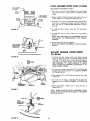
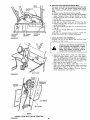
UPPER
STEERING
SHAFT
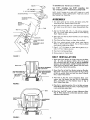
Slide Upper Steering Shaft over Lower Steering Shaft until
boil holes line up with slots in Lower Steering Shaft (Fig,
1),
2,
BOLTS
LOWER
SHAFT
3_
Use two Hex Bolts 3/8 - 16 x t . 1/4 and two Locknuts
3/8 - 16 to retain Upper Steering Shaft to Lower Steering
Shaft Tighten securely.,
4o
Stide Tube over
Sleeve Bracket
5_ Place Steering
STEERING
6. With
SLEEVE
Wheel
should
BRACKET
Steering
Wheel
Adapter
Remove
SEAT
,
SEAT
HEX
AND
HE×
5t!6
SHOULDER
- 18 & LOCK
BOLT
NUT
- 18 & LOCK
BOLT
NUT
FENDER
SEAT
/
5/16
BOLTS, WASHERS
LOCK NUTS
on Upper
front
wheels pointed
straight
on Steering
Wheel Adapter-,
point straight across tractor,
8 Snap Insert into Steering
9
1
Assembly
Place 2 - 1/4"
Dia, Washer on Upper
stall a 1/2" Nut, Tighten securely,
7o
FIGURE
Shaft
plastic
on Tractor
and over Steering
Steering
Shaft,
ahead, place Steering
Bars of Steering Wheel
SteeringShaft
and in-
Wheel,
Hood
iNSTALLATiON
Mount Seat Pivot Bracket to Fender using two Hex Bolts
3/8 - 16 x 3/4, two Washers t3/32 x 3/4 x 10 Ga. and,
two Crownlock Nuts 3/8- 16 (Fig, 2). NOTE; WASHERS _
SHOULD BE POSITIONED UNDER FENDER NEXT TO
NUTS. Seat Pivot Bracket, Bolts, Washers and Nuts found
in Bag of Parts° Tighten Nuts securely.
2. Mount Seat Pan to Seat Pivot Bracket using two Shoulder
BOlts 5/16 - 18 and two Lock Nuts 5/16- 18 (Fig. 2) (head
of Bolts to outside)_ Bolts and Lock Nuts found in Bag of
Parts, Tighten Nuts secureFy,
BRACKET
3_
Place Seat on Seat Pan,. Screw Adjustment
Bolts, Lockwashers and Flat Washers into Seat (Fig. 3), Adjustment
Bolts, Lockwashers and Flat Washers found in Bag of
Parts, Tighten finger' tight,
4_
Place Seat in operating position° Sit on the Seat and press
Clutch-Brake Pedal all,the way down. if operating position
is not comfortable, adjust Seat,
FIGURE 2
J
CLUTCH/BRAK
PEDAL
5. Raise Seat. Use 9/t6" wrench to loosen Adjustment Bolts
(Fig, 3), When adjusted for' comfortable operation, tighten
Adjustment Bolts securel¥o
E
/
FIGURE 3
- 4 -
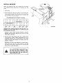
BATTERY
ONSTALLATDON
WEAR
EYE AND
FACE
SHIELD..
CUT
AWAY
VIEW
VENT
WASH
HANDS
OR CLOTHING
IMMEDIATELY
tF ACCIDENTALLY
IN CONTACT
WITH ELECTROLYTE°
DO NOT SMOKE,
ED ELECTROLYTE
CAP
BATTERY
TUBE
FUMES
FROM CHARGARE EXPLOSIVE.
BATTERY
CELL
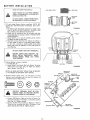
1. Fill and charge Battery (before installing), NOTE: SEE
DETAILED
iNSTRUCTIONS
PACKAGED
WITH BATTERY.
ao Fill Battery with electrolyte to bottoms of tubes in cells
(Fig, 4). NOTE: DO NOT OVERFILL.
OVERFILLING
WILL RESULT 1N DAMAGE TO TRACTOR.
b. Check level of electrolyte after 30 minutes° Add additional electrolyte if necessary. NOTE: TIGHTEN VENT
CAPS SECURELY_
c. Charge Battery at a rate not exceeding three amperes
for about two and one half hours.
do Neutralize excess electrolyte for disposal by adding it
to four inches of water in a five gallon plastic container., Stir with a wooden or plastic paddle while adding
baking soda until the addition of more soda causes no
more foaming.
DO NOT SHORT BATTERY
FIGURE
SEAT
FENDER
WELL
TERMINALS.
BEFORE METAL
INSTALLING
BATTERY,WRISTREMOVE
BRACELETS,
WATCH
BANDS,
RINGS,
ETC. FROM
YOUR PERSON,,
POSITIVE
2 Position Battery in tractor as foltows:
a. Lift Seat (Fig. 5),
b., Lower Battery into Fender Wel! with Battery Terminals
toward front of tractor (Fig, 5),, Make sure Battery
rests in Battery Tray (Fig,, 6).
BATTERY
TERMINAL
size below)
Battery
Cables using:
two Lockwashers
and
found
two
two
Hex Bolts, two
Hex Nuts (shown
b.
Flat
full
in Bag of Parts,
Connect
RED Battery
Cable to Positive (+) Battery
Tero
minal with
Hex Bolt, Flat Washer. Lockwasher
and Hex
Nut (Fig. 6). Tighten
securely.
Connect
BLACK
Ground
Cable to Negative
(-) Battery
Terminal
with
remaining
Hex Bolt, Fiat Washer, Lockwasher
and Hex Nut
(Fig° 6). Tighten
I
BATTERY
TERMINAL
FIGURE
POSITIVE
TERMINAL
MUST BE CONNECTED
FIRST TO PREVENT SPARKS
F ROM ACCIDENTAL
GROUNDING
a
NEGATIVE
BATTERY
NOTE: BE SURE BATTERY DRAIN TUBE IS SECURELY ATTACHED TO BATTERY TRAY DRAIN.
3. Connect
Washers,
4
securely°
-5-
5
4,
WING
Install
Battery
using: two Int./Ext
Nuts (shown full size below} and
NUT
Lockwashers,,two
Wing
INTERNALIEXTERNAL
LOCKWASHE
R
TERMINAL
GUARD
q=D
WING
INTERNAL/
EXTERNAL
LOCKWASHER
0
\
BATTERY
BOLT
two Battery Bolts and one Terminal Guard found in Bag of
Parts.
ao Using the slot on one side of the Battery Support (Fig.
6A) slide Battery Bolt into Frame Slot (head of Bolt
down}. Fasten the Battery Bolt to the Terminal Guard
using IntjExt°
Lockwasher and Wing Nut as shown in
Fig. 6Ao
b. Assemble the remaining Battery Bolt to other side of
Battery Support and fasten Terminal Guard to it with re,
maining Int,/E_t_ Lockwasher and Wing Nut° Tighten
Wing Nuts securely by hand (Fig. 6A).
NOTE: USE TERMINAL ACCESS DOORS (F tG.6A) FOR:
1, Inspection for secure connections (tighten hardware).
2. inspection for corrosion,
3, Testing battery,
4, Jumping (if required).
5_ Charging (if required).
FIGURE 6A
WHEN NOT IN USE, KEEP TERMINAL
ACCESS DOORS CLOSED,
NOTE: DO NOT START ENGINE UNTIL
VICE
HAS BEEN PERFORMED,
INITIAL
INITIAL
SER-
ADJUSTMENTS
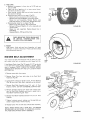
1. TIRE PRESSURE
Reduce Tire pressure to t4 PSI in front tires; 12 PSI in
rear tires, (Tires were overinflated for shippingL
SCREW
FIGURE 7
.
/
HEADLIGHT
CONNECTION
FIGURE 8
-6 -
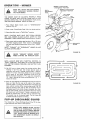
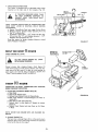
HOOD
a. To raise Hood, lift at rear of Hood.
b. Unsnap Headlight Connection (Fig, 8).
c,. To remove Hood, Grill and Side Panels, raise Hood and
loosen one screw on each Side Panel. (The screw remains
in the Side Panel) (Fig, 7)._
d, Stand in front of Tractor_ Grasp Hood and titt forward
and lift off (Fig. 8),
e, To reinstall, reverse above procedure..
INaTIAL
SERVnCE
NOTE: BE CAREFUL NOT TO ALLOW DiRT TO ENTER
THE ENGINE WHEN CHECKING
OR ADDING OIL OR
FUEL
I.,Open
OIL
FILLER
Hood.
2. Check Engine Oil Leve! with Tractor
on level ground
Remove and wipe Dipstick
(Fig, 9) clean, screw it in tight for
a few seconds, remove and read Oil Level if necessary, add
Oil until "FUEL"
mark is reached
RECOMMENDED
SAE VISCOSITY
FUEL
CAP
GRADES
L!i,!ii!I !....
z
f
.....
sw2o0._w3o'
.......
FUEL
TANK
"--4
.........
I 1:, ....I....ti:.......
-20 o
0°
32 °
60 °
80 °
FIGURE
100 °
TEMPERATURE
RANGE EXPECTED BEFORE NEXT OIL
CHANGE° ALL OILS MUST MEET A.P.L SERVICE CLASSIFICATION SD, SE, OR SF,.
Capacity is 2 pints° NOTE: DO NOT OVERFILL
Dipstick
assembly must be securely tightened into tube at all times
when engine is operating.
3. Fill Fuel Tank (Fig.. 9). Use fresh, clean, unleaded automotive gasoline° (Leaded "Regular " grade gasoline
"
" not an
ts
acceptable substitute° Use of leaded gasoline wilt increase
carbon and lead oxide deposits and reduce valve life).
Capacity is 5 quarts..
WARNING:
DO NOT USE GASOHOL OR METHANOL.
These type fuels react with water content in the fuel
and tend to form strong acids which can corrode metal
parts and harm rubber and plastics.
FILL TO BOTTOM OF GAS TANK FILLo
ER NECK, DO NOT OVERFILL.
WIPE
OFF ANY SPILLED OIL OR FUEL, DO
NOT STORE, SPILL OR USE GASOLINE
NEAR AN OPEN FLAMEn
-7-
9
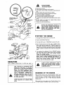
CAUTION
TO AVOID
CHOKE
FAST
MOWERBLADE
CLUTCH"ENGAGED'_
POSITION
"DISENGAGE
POSITION
D"
HEADLIGHT
I, Read owners manual,
2, Know location and function of all controls°
3o Keep guards, safety shields and switches in place and working,
4. Remove objects that can be thrown by blades..
5. Do not mow when children and others are around.
6_ Never carry chitdren or passengers,
7o Always look behind machine before backing,
8o Do not mow where machine can tip or slip,
9, If machine stops going uphill, stop blade and back slowly
down,
t0o Be sure blades and engine have stopped before placing
hands or feet near the blades,
11_ Remove key when leaving machine.
PARKING
BRAKE
THROTTLE
DO NOT ADD ADDITIONAL
WEIGHT TO
THE TRACTOR OTHER THAN THE OPTIONAL WHEEL WEIGHTS. EXCESSIVE
WEIGHT MAY OVERLOAD
AND DAMAGE THE TRANSMISSION.
"tON
_CONTROL
LEVER
INJURY
"DISENGAGED"
POSITION
/
GEARSHIFT
LEVER
_I_=
STARTING
CLUTCH!BRAKE
"CLUTCH"
POSIT,ON
"C LUTCH/BRAK
POSITION
FIGURE 10
E"
THE
ENGINE
1_ Disengage Mower Blade Clutch Lever (Fig_ 10)_
_"_ _.
2. Depress Clutch!Brake Pedal fully._
3. Place Gear Shift Lever in "NEUTRAL"
"
:
_
_
LIFT
LEVER
/PLUNGER
4_
LIFT
5_
FIGURE
11
position (Fig. 10)o
Move Throttle Controt Lever (Fig. 10) to "FAST" detent,
then to the right and upward for "CHOKE" position, At
the "FAST" position the Lever has a stop. The stop is provided so that you will know when you are at full throttle
ttFASTt' position and prevent over travel into choke posio
tion,
Turn Ignition Key clockwise (('_)
to "START"
position
and release Key as soon as engine starls (Fig. 10).tmmedi_
ately move Throttle Control Lever mid-way between
"FAST" and "SLOW" positions.
NOTE: DO NOT RUN STARTER CONTINUOUSLY
FOR
MORE THAN FIFTEEN
SECONDS PER MINUTE.
If
Engine does not start after severalattempts, move Throttle
Control Lever mid-way between "FAST" and "SLOW"
positions, wait a few minutes and try again.
OPERATION
NOTE:
MOWER
OPERATION
IS LISTED
ON PAGE
ALWAYS WEAR SUBSTANTIAL
FOOTWEAR AND AVOID
LOOSE FITTING
CLOTHING THAT COULD GET CAUGHT
IN MOVING PARTS.
tl.
THIS TRACTOR
IS EQUIPPED
WITH
INTERLOCK
SWITCHES TO PREVENT
STARTING
OF THE TRACTOR ENGINE
WHILE THE MOWER BLADE CLUTCH
LEVER
IS IN THE "ENGAGED"
POSITION AND/OR THE FOOT PEDAL IS NOT
FULLY
DEPRESSED.
IMMEDIATELY
REPLACE SWITCHES THAT ARE NOT
IN PROPER WORKING ORDER. DO NOT
ATTEMPT
TO DEFEAT THE PURPOSE
OF THESE SWITCHES°
LEARN TO START, STOP AND REVERSE
YOUR TRACTOR
IN A LARGE, OPEN
AREA
WARMING
UP
THE
ENGINE
Move Throttle Control Lever mid-way between "FAST" and
"SLOW" positions (Fig, 10). As engine warms up, move Throttle Control Lever to "FAST" position, NOTE: ALLOW ENGINE TO WARM UP FOR A FEW MINUTES
BEFORE
OPERATING.
When restarting a warm engine move Throttle Control Lever
FAST poszt4on, CHOKE may not have to be used,
-8- to
11
$'
_
•
11
,t r
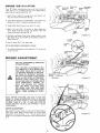
MOWER
Your
38"
INSTALL.ATnO_
Mower
installs
without
CLUTCH
ROD
the
use of tools
Lever (Fig° 11) to its highest position.
ment Knob to lowest position
(Fig 14)
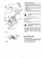
!o Instal!
Front
Hinge
(Fig. 12). Secure with
2
Install
Parallel
Rear
Link
3
Install
Clutch
Turn
Pin through
Axle
Retainer Spring°
Raise
Depth
Lift
in Clutch
Lever (Fig,
and
Parallel
(Fig_ t!)
_'_
and
Suspension
holes and
FRONT
HINGE
PiN
REAR
HINGE
P_N
FIGURE
12
CLUTCH
LEVER
to raise mower
NOTE: SEE MOWER ADJUSTMENT,
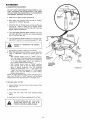
7, Turn Depth Adjustment
die of it's travel_
RETAINER
SPRINGS
Link
5o Roll Belt over Mower Drive Pulley
Make sure Belt is inside
Belt Guides
(Fig. 14), See Belt Drive Schematic
Decal on
Mower Housing
Lever
FRONT
AXLE
13 - Inset),
4. Move Lift
Lever (Fig,
11) forward
to lower
Arms,
Stide Trunnions
through
Lift
Bracket
secure with Retainer Springs (Fig. 13)
6, Use Lift
CLUTCH
LEL
BRACKET
Hinge Pin through
Mower
Lift Brackets
(Fig, 12)Secure
with Retainer Spring
Rod
SPRING
Adjust-
PARAt
LINK
RETAINER
Knob
CLUTCH.
ROD
BELOW,
clockwise
(('_,)to
the midSUSPENSION
ARM
RETAINER
SPRING
MOWER
ADJUSTMENT
FOR ANY ADJUSTMENTS,
OR MAINTENANCE:
INSPECTION
PUSH TRACTOR
CLUTCH-BRAKE
PEDAL COMPLETELY
INTO BRAKE POSITION,, MOVE GEAR SHIFT LEVER TO
"N" NEUTRAL POSITION, PLACE PARKING BRAKE IN "ENGAGED"
POSITION.
SHUT OFF THE ENGINE. PLACE MOWER
BLADE CLUTCH LEVER IN "ENGAGED"
POSITION,, MAKE ABSOLUTELY
SURE
THE BLADES AND ALL MOVING PARTS
HAVE
COMPLETELY
STOPPED,
REMOVE
THE IGNITION
KEY, DISCONNECT THE SPARK PLUG WIRE FROM
THE SPARK PLUG AND KEEP WIRE
AWAY FROM THE PLUG TO PREVENT
INJURY
FROM ACCIDENTAL
STARTING.
RETAINER
SPRING
LIFT
BRACKET
FIGURE
TRUNNION
\
3ELT
MOWER
DRIVE
PULLEY
13
\
NOTE: BEFORE CHECKING
THE SIDE TO SIDE AND
FRONT TO REAR ADJUSTMENTS,
PAGE 10, BE SURE
PRESSURE IN FRONT TIRES IS 14 PSi AND PRESSURE
IN REAR TIRES IS 12 PSI IF TIRES ARE OVER OR
UNDER INFLATED
YOU WILL NOT PROPERLY ADJUST
YOUR MOWER,
DEPTH ADJUSTMENT
Adjustm#nt
for mower height is made with the Depth Adjustment Knob,
Raise Mower
cutting
height by turning
Depth
Adjustment
Knob clockwise
( _
) Lower Mower cutting
height
by turning
Depth Adjustment
Knob counterclockwise
FIGURE
-9-
14
LEVEL
LIFT
PLUNGER
MOWER
FROM
SEE MOWER ADJUSTMENT,
TO SiDE
PAGE 9.
t_ Park tractor on level surface_ Depress Lift Lever Plunger
and use Lift Lever to raise mower to maximum cutting
height,
LIFT
LEVER
SI DE-TO-SI DE
:3JUSTMENT
TOP OF
FLANGE
TOP OF
FLANGE
A
FIGURE 15
,
Measure height
ofIt Top
of Flange to level surface at front of
,
_t
mower. D_stance A should be the same (Fig. I5)o
m
If distance "A" needs to be changed, snap out Access Hole
Cover on LHo side above Footrest. Use 9/16" wrench on
Nuts "B" and "C" at Side-To-Side Adjustment Trunnion
(Fig 16),
A
4_ To raise left side of mower, loosen Nut m*Bm'and tighten
Nut "Ctl_
e
To lower left side of mower, loosen Nut "C" and tighten
Nut "B'o
NOTE: ONE ROTATION
OF ADJUSTMENT
NUTS IS
EQUIVALENT
TO APPROXIMATELY
3/16" HEIGHT
CHANGE,
.
Be sure all nuts are securely tightened°
NOTE: SEE MOWER ADJUSTMENT,
BELOW_
SIDE-TO.SIDE
ADJUSTMENT
TRUNNION
ADJUST
MOWER
TO REAR
FIGURE
SIDE
16
,
REAR
SUSPENSION
ARM
\
FROM
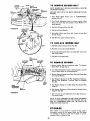
FRONT-TO-REAR,
FRONT
To obtain the best cutting results, your Mower Housing
should be adjusted so the Front and Rear Flange distance
"D" (Fig_ 17) is 5/16" lower in front when the mower is
positioned in the hinhest cutting position._ NOTE: MEASURE DISTANCE
_XD_ FROM SURFACE
TO RIGHT
REAR FLANGE AND COMPARE TO DISTANCE "D" AT
RIGHT FRONT FLANGE°
2, To raise rear of mower, loosen Nut "E" on both Rear SuEpension Arms. Screw both Nuts "F" up EQUAL NUMBER
OF TURNS (Fig= 18)_
i_REAR
/FLANGE
3. When distance "D"
en Nut "E'o
D
REAR
SUSPENSION
TRUNNION
LIFT
BRACKET
4. To lower rear of mower, loosen Nut "F" on both Rear
Suspension Arms an EQUAL NUMBER OF TURNS (Fig.
18).
FRONT
FLANGE
5_ When distance S'D" is 5t16"
tighten Nuts _'E'.
FIGURE 17
NOTE: WHEN ADJUSTING
NIONS, ALWAYS ADJUST
WILL STAY LEVEL.
NUT
REAR
SUSPENSION
TRUNNION
NUT
FIGURE 18
is 5/1B" lower at front than rear, tight_
REAR
SUSPENSION
ARM
LIFT
BRACKET
"F"
.10 -
lower at front than rear, re=
REAR SUSPENSION TRUNBOTH EQUALLY
SO MOWER
OPERATUO
= MOWER
READ
THE
"RULES
FOR
TION"
CAREFULLY
ING YOUR MOWER,
MOWER
CLUTCH
'*DISENGAGED"
SAFE
BEFORE
OPERA-
DEPTH
ADJUSTMENT
KNOB
OPERAT-
LEVER
POSITION
MOWER
CLUTCH
LEVER
"ENGAGED"
POSITION
LIFT
LtFT
LEVER
THE
MOWER
MUST
BE ADJUSTED
PROPERLY
FROM
FRONT
TO REAR
AND
LEVELED
FROM SIDE TO StDE
BEFORE
OPERATING,,
THtS IS NECESSARY
FOR LEVEL
AND EFFICIENT
MOWING
REFER TO PAGE 10
1. Place
Mower
position
2, Push
(Fig.
tractor
Blade
Clutch
Lever
in
LEVER
"DISENGAGED"
19)
Clutch-Brake
3, Place Gear Shift
Lever
Pedal
fully
in _'NEUTRAL"
into
brake
position
position
NOTE: TRACTOR
MUST HAVE FOOT PEDAL DEPRESSED AND MOWER BLADE CLUTCH
LEVER IN "DISENGAGED"
POSITION BEFORE TRACTOR W1LL START
4, Start tractor and set engine speed to about 1/3 to 1/2 throttle before engaging mower, After mower is "ENGAGED"
and you have started forward travel, set to FULL THROTTLE,
NOTE: "ENGAGE"
OR "DISENGAGE"
MOWER BLADE
CLUTCH LEVER SLOWLY,
_ARGE
GUARD
FIGURE
19
FIGURE
20
NEVER SITTING
"ENGAGE"ON MOWER
WHEN
TRACTOR EXCEPT
SEAT.,
NOTE: ALWAYS MOW WITH THROTTLE
CONTROL IN
"FAST"
POSITION. THIS RESULTS IN BETTER GRASS
CUT, BETTER ENGINE COOLING, AND BETTER FUEL
ECONOMY°
f
T
5, Use Lift Lever to iower mower into cutting position Start
mowing in the first gear and increase ground speed as
conditions will permit. Average cutting height is approximately 2 - t/2 to 2 - 3/4 inches, Height of cut can be adjusted by means of the Depth Adjustment
Knob (Fig° 19)
Moving the Knob clockwise (_)
raises the mower (Fig.
t4 - Inset).. Moving the Knob counterclockwise
( _
)
lowers the mower.
6
Drive so that clippings
are discharged onto the area that has
been cut, Have the cut area to the right of the machine
This will result in a more even distribution
of clippings
and
more uniform
cutting., When mowing
large areas (Fig, 20)
start by turning
to the right so that the clippings
will be
discharged
away from shrubs, fences, driveways,
etc After
two or three rounds, mow in the opposite direction
making
left hand turns until finished,
if grass is extremely
tall, it
should
be mowed twice
The first time cut relatively
high.
The second time to the desired height. The felt hand side
of mower should be used for trimming,
FLQP=UP DUSCNARGE
GUARD
Your mower has a flip-up
Discharge Guard (Fig.
or gate clearance when held in raised position
19) for door
MAKE
SURE
MOWER
BLADE
CLUTCH
LEVER
tS IN "DISENGAGED"
POSITION
AND BLADES
HAVE
STOPPED
BEFORE
RAISING
DISCHARGE
GUARD
(DEFLEC,
TOR),
NEVER
OPERATE
MOWER WITHOUT DISCHARGE
GUARD
IN OPERATING POSITION,,
-!I
-
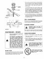
When grinding,
care should be taken to maintain
blade balance and the blade should
be checked
for proper balance
before reinstatlation
on mower,
Unbalanced
or bent blade
will
cause excessive
damage to mower
balanced blades,
MANDREL
ASSEMBLY
__i
2
_
_
.ExeOLT
/
FIGURE 21
t
!
I
'
...........
/
CENTER
HOLE
running,
bent,
and eventual
damaged
or un-
To ensure satisfactory
operation,
it is recommended
that
before the start of each mowing
season, the old blades be
discarded
and replaced with new blades. Mower blades can
be purchased at any Sears Service Center/Departments
and
most Sears Retail Stores=
DAI LY
J
|
when
Replace
To check Blade balance, drive a nail into a beam or wall.
Leave about one inch of the straight nail exposed. Place
Center Hole of clean Blade over the head of the nail (Fig,
22). NOTE: CENTER HOLE OF BLADE ON NAIL
IF
BLADE tS PROPERLY BALANCED,
BLADE SHOULD
REMAIN IN POSITION SHOWN IN FIG 22. IF EITHER
END OF THE BLADE MOVES DOWNWARD, BLADE IS
NOT BALANCED AND MUST BE REPLACED.
FLANGES
LOCKWASHER
vibration
or engine
MAI
NTENANCE
Make sure all nuts on bolts are tight and cotter pins and retain,,
er springs are secure° Keep blades sharp. Observe all safety precautions
Keep mower well lubricated
(refer to page 22},
I
.........
i
CLEANING
MOWER
DISCONNECT
SPARK PLUG WIRE
PREVENT ACCIDENTAL
STARTING
FORE CLEANING.
TO
BE-
FIGURE 22
Water- pressure from a garden hose will remove fresh clippings
from underside of mowen Clean mower after each mowing_
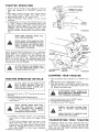
MAINTENANCE
= MOWER
BLADE
FOR ANY ADJUSTMENTS,
OR MAINTENANCE:
INSPECTION
Raise Mower to highest position to permit
1_ Remove Bolt, Lockwasher and Washer
counterclockwise
(f'_}_
PUSH TRACTOR
CLUTCH=BRAKE
PEDAL COMPLETELY
INTO BRAKE POSITION,
PLACE
PARKING
BRAKE
IN
"ENGAGED"
POSITION.
MOVE GEAR
SHIFT
LEVER
TO "NEUTRAL"
POSITION, PLACE MOWER BLADE CLUTCH
LEVER
IN "DISENGAGED"
POSITION.
TURN IGNITION
KEY TO "OFF" POSITION. MAKE ABSOLUTELY
SURE THE
BLADES
AND ALL
MOVING
PARTS
HAVE
COMPLETELY
STOPPED,
REMOVE THE IGNITION
KEY, DISCONNECT 'THE SPARK PLUG WIRE FROM
THE SPARK PLUG AND KEEP WIRE
AWAY FROM THE PLUG TO PREVENT
INJURY FROM ACCIDENTAL STARTING°
BLADE
to sharpen
while
(Fig.
2!)
(turn
ALWAYS USE GRADE 5 HEAT TREATED
BOLTS TO ATTACH
BLADES, CHECK
BOLTS IN BLADES OCCASIONALLY
TO
MAKE SURE BOLTS ARE TIGHT° TORQUE BOLTS 30 - 35 FTo LBS_
A GRADE 5 HEAT TREATED BOLT
CAN BE IDENTIFIED
BY THREE
LINES ON THE BOLT HEAD AS
SHOWN AT LEFT°
CARE
Do not attempt
access to Blades_
2. Place new Blade between Flanges, (the word "TOP" is
stamped on all Blades to assure proper installation), and
secure with Washer, Lockwasher and Bolt previously removed, TIGHTEN SECURELY..
For best results mower blades must be kept sharp, The blades
can be sharpened
with a few strokes of a file or on a grinding
wheel° We suggest they be sharpened
after every 15 hours of
mowing,
REPLACEMENT
on mower,
_12_
TRACTOR
OPERATION
LEVER
1, Depress Lift Lever Plunger at top of Mower Lift Lever and
move Lever rearward to its "HIGHEST"
position (Fig
23).
2, With engine running and warm, place Throttle Control
Lever midway between "FAST" and "SLOW" position
3, Move Gear Shift Lever to "1ST" Gear (Fig 24)
4_ Release Clutch-Brake
Pedal SLOWLY to start forward
movement,
5, tf ground travel is too slow, move Throttle Control Lever
to
AST
posltmon or press Clutch-Brake Pedal to stop
and shift to a different gear. NOTE: ALWAYS SELECT A
GROUND
TRAVEL
SPEED THAT WILL SUIT THE
TERRAIN
AND THE ATTACHMENT
BEING
USED,
NEVER CHANGE GEARS WHILE TRACTOR
IS MOVING.
MAKE
SURE PARKING
BRAKE
HOLD TRACTOR SECURE
PLUNGER
MOWER
LIFT LEVER
"HIGHESTPOSITION
\
"*LOWEST"
POSITION
FIGURE 23
WILL
NEVER PLACE YOUR HANDS OR FEET
IN OR UNDER ANY POWERED ATTACHMENT OR NEAR ANY MOVING PART
WHILE TRACTOR
OR ANY POWERED
ATTACHMENT
IS RUNNING,
NOTE: ALWAYS OPERATE ENGINE AT FULL THROTTLE
WHEN MOWING TO ASSURE BETTER MOWING PERFORMANCE,
LONG ENGINE LfFE AND PROPER DISCHARGE
OF CUT MATERIAL
REGULATE
GBOUND
SPEED BY SELECTING
A LOW ENOUGH GEAR (FIG,
24) TO GtVE THE MOWER CUTTING PERFORMANCE
PLUS QUALITY OF CUT DESIRED
OUT THE DEFLECTOR
SHIELD
(DISDO NOT OPERATE THE MOWER WITHCHARGE GUARD) IN PLACE,
PARKING
BRAKE
"ENGAGED'"
'ION
"DISENGAGED"
POSITION
"CLUTCH"
POSITION
I
"CLUTCH/BRAK
POSITION
E'>' "DRIVE"
"_ POSITION
STOPPING
TRACTOR
OPERATOON
ON NIILLS
YOUR
t
Move
down
Gear
hills.
Shift
Lever to "1ST"
Gear before
starting
2, AVOID
STOPPING
OR SHIFTING
ON HILLS
a, If slowing
is necessary, move Throttle
Control
slower
Lever to
LEAVE
ENOUGH
ROOM
WHEN
7 -
FIGURE 24
TRACTOR
.
It
.
II
,
,
CLUTCH-BRAKE
PEDAL SHOULD REMAIN COMPLETELY
DEPRESSED WHEN
FOOT PRESSURE IS RELEASED,
up or
position
f_
_/._
I Push ClutchoBrake Pedal completely into "BRAKE"
position,
2, Move Gear Shift Lever to _'NEUTRAL" position,
3, Place Parking Brake m ENGAGED
position= Raise Parking Brake Lever and hotd in "ENGAGED"
position (Fig,
24), Release Clutch-Brake Pedal
•
WITH
SLOPES GREATER
THAN
1
DO NOT
UP OR ACROSS
DOWN HILLS
AND
DO DRIVE
NOT DRIVE
ANY
SLOPE, REFER TO PAGE 43.
GEAR
LEVER/.
CLUTCH/BRAKE,,_
4
5
6
Move Throttle
Control
Lever to "SLOW"
Disengage Mower Blade Clutch Lever
Turn Ignition
Key to "OFF" position
position
STOP-
SLIGHT
TRACTOR
ROLL
DOWNHILL
PING
AND
STARTING PEDAL
TO ALLOW
AS
CLUTCH-BRAKE
MOVES
THROUGH CLUTCH POSITION
b. If stopping is absolutely necessary, push Clutch-Brake
Pedal quickly
to brake position and engage Parking
Brake=
c., To restart tractor movement, make sure tractor is in the
II
ti
lowest speed range ( 1ST Gear) and that you have
allowed room to roll slightly downhill. Depress ClutchBrake fully, Disengage Parking Brake and release ClutchBrake Pedal SLOWLY
to start tractor
movement.
3,, Make all turns gradually
- 13-
REMOVE
TOR
TO
USE.
KEY WHEN
PREVENT
LEAVING
TRACUNAUTHORIZED
BRING TRACTOR TO COMPLETE
BEFORE SHIFTING GEARS
TRANSPORTIING
YOUR
STOP
TRACTOR
For pushing or towing your tractor, place Gear Shift Lever
in "NEUTRAL"
plosition (Fig 24) Push Clutch-Brake Pedal
down firmly to
DISENGAGE
Parking Brake (Fig.-'2;_}::
NOTE: DO NOT TOW YOUR TRACTOR
FASTER THAN
S!X MILES PER HOUR_
STARTING
YOUR
A LOW BATTERY
TRACTOR
MAINTENANCE
WtTN
MOWER MAINTENANCE
GROUNDED
F_EFER TO "STOPPING
TOR"
PAGE
13 AND
SYSTEM
2
Connect
terminals
each end of the
of each battery
chassis),
Connect
one
BAILY
RED Cable to the POSITIVE
(+)
(taking
care not to short against
end of the BLACK
Cable
(,-) terminal
of futIy charged battery
3. Connect
the other end of the cable
to
or good CHASSIS
GROUND
on tractor
Tank or Battery)
4, Disconnect
cables in reverse order:
a Engine Block or chassis of tractor
b. Negative terminal
of fully charged
c, Positive terminals
to the
Make
ENGINE
(away
BLOCK
from
FIRST
FIGURE 26
on
bolts
are tight
and
cotter
pins
and
precautions,
_
HOURS
I, CHANGE ENGINE OIL
Changing Oil after the first two hours will help eliminate
break-in residue which might be damaging to your" Engine
NOTE: BE CAREFUL NOT TO ALLOW DIRT TO ENTER
THE ENGINE
WHEN CHANGING
OIL.
battery,
a Drain Oil with Engine warm Loosen Oil Drain Wing
Nut (Fig. 25) and remove Dipstick. Catch Oil in a suit _.
able container. Tighten Oil Drain Wing Nut
b, Refill Engine Oil. See oil chart, page 7. Refill capacity is
2 pints. NOTE: DO NOT OVERFILL.
Replace Dipstick
1. CHECK BATTERY
a Electrolyte solution tevet in each Battery CelI should be
even with bottoms of tubes in cells (Fig. 261. Add dis=
tilled water if necessary NOTE: DO NOT OVERFILL
b Keep Battery and Terminals clean
c. Keep Battery Bolts tight,
d Keep Vent Caps tight and small Vent holes in Caps
open,
e Recharge SLOWLY at 3 amperes if necessary.
2, CHECK TIRE PRESSURE
Tire pressure in front Tires should be t4 PSI; rear Tires
12 PSI
3, CLEAN AIR SCREEN
Air Screen (Fig. 25) must be kept free of dirt and chaff to
prevent Engine damage from overheating.
OIL DRAI
wING
NUT
FIGURE 25
•
nuts
FREOUENTLY
//
VIEW
sure all
Gas
FUEL FILLER
CAP
AWAY
MAINTENANCE
NEGATIVE
AIR
SCREEN
CUT
YOUR TRACDISCONNECT
retainer
springs are secure Observe
all safety
Keep tractor well lubricated
(refer to page 22)
TERY
TO USE
START
VEHICLES,
DO NOT
YOUROTHER
TRACTOR
BAT..
_l
neces-
CIDENTALPLUG
SPARK
STARTING
WIRE TO
BEFORE
PREVENT
MAKING
AC.
ANY
INSPECTION,
ADJUSTMENT
OR
REPAIR (EXCEPT CARBURETOR),
LEAD-ACID BATTERIES GENERATE EX,.
PLOSIVE GASES. KEEP SPARKS, FLAME,
AND
SMOKING
MATERIALS
AWAY
FROM BATTERIES. ALWAYS WEAR EYE
PROTECTION AROUND BATTERIES,
1
iS LISTED ON PAGE t2,
To keep your tractor running better longer; perform
sary service using the following Maintenance Schedule
if your" Battery
is too tow to start the engine,
it should be
recharged,
If "Jumper
Cables" are used for emergency starting
follow
this procedure
NOTE:
YOUR
TRACTOR
IS EQUIP.PED WITH A 12 VOLT
NEGATIVE
GROUNDED
SYSTEM,
THE OTHER
VEHICLE
MUST ALSO BE A 12 VOLT NEGATIVE
= TIRACTOR.
VENT
CAP
BATTERY
-14-
4, CHECK BRAKE OPERATION
This tractor is equipped with an adjustable brake system
mounted on the right side of the transaxle (Fig., 27).
BRAKE
tF TRACTOR
REQUIRES
SIX
FEET GEAR,
STOPPING
HIGHEST
THEN
BE ADJUSTED,,
MORE
THAN
BRAKE
DISTANCE
tN
BRAKE MUST
NOTE: PARKING BRAKE MUST BE DISENGAGE D AND
GEAR
SHIFT LEVER
IN NEUTRAL
WHILE
MAKING
ADJ USTM ENT.,
ao Depress Clutch-Brake Pedal and engage Parking Brake°
bo Measure distance between Brake Operating Arm and
Nut "A" on Brake Rod
.
.
I)
c. if distance ts other than 1 - 1/2 , loosen Jam Nut (Fiq.
•
is
t_
.
,
/3
27) and turn NUt A untd d_stance becomes t - 1/2 .
Retighten Jam Nut aga nst Nut A ,,
Road test tractor for proper stopping distance as stated
above.. Readjust if necessary=
*
irl
OPERATING
ROD
\
JAM NUT
ARM
0 ........
1.1/2-
0
O, CBBAK
j
F1GURE 27
G3
DAILY
OR EVERY
HOURS
ENGINE
OIL
FILLER
CAP
AND DIPSTICK
CHECK ENGINE OIL LEVEL
AIR
COVER
\
DO NOT CHECK ENGINE
WITH ENGINE RUNNING.
OIL
LEVEL
Several minutes after stopping Engine, check Engine Oil
Level with Tractor on level ground,, Remove and wipe Dipstick clean (Fig, 29), screw it in tight for a few seconds, remove slowly and read Oil level. If necessary, add Oil until
"FULL" mark is reached DO NOT OVERFILL
6vs.v
.=..s
(OPERATING
IN DUSTY CONDITIONS
MORE FREQUENT SERVICING)
MAY
AIR
CLEANER
BODY
REQUIRE
1. CLEAN AIR CLEANER ELEMENT (FIG. 28)
ao Open Hood,
b. Snap off Air Cleaner Cover°
c,. Remove Foam Element from Air Cleaner Body.
d. Wash Foam Element in liquid detergent and water to
remove dirt..
eo Wrap foam in cloth and squeeze dry.
f_ Saturate foam in clean engine oil Squeeze to remove
excessoil=
g,, Replace Foam Element and snap Cover on Air Cleaner Body,
NOTE: NEVER
MOVED.
2. CHANGE
FOAM
ELEMENT
RUN ENGINE
ENGINE
WITH AIR
CLEANER
FIGURE 28
RE-
OIL
The best time to change Engine Oi{ is at the end of a day's
operation
when all dirt and foreign materiafs are suspended
in the hot Oii_ See oil chart, page 7
-15-
AIR
SCREW
CLEANER
COVER
_"_
3. CLEAN ENGINE COOLING FINS
Keep Engine Cooling Fins free of dust, dirt and oil to prevent Engine damage from overheating.
a. Snap Cover off Air Cleaner (Fig. 29L Remove Hex
Head Screw from inside Air Cleaner. Remove two
Slotted Head Screws from rear of Air Cleaner. Pull Air
Cleaner' off.
b, Remove two Hex Head Screws from front of Blower
Housing_ Remove two Hex Head Screws from side of
Blower Housing_
co Pull Blower Housing off.
Cytinder Head Cover may also be removed° Clean Engine
Cooling Fins with a stiff bristled brush or compressed
air'_.
--__
_,
k
BLOWER
HOUSING
SCREW%
SCREW
HEX HD
SCREW
WEAR SAFETY GLASSES IF USING COMPRESSED AIRo
COOLING
d. To reassemble, reverse above procedure,
HEX
HD
FINS
SCREW
NOTE: PRESS BREATHER
AIR CLEANER (FIG. 29).
TUBE
INTO
BOTTOM
OF
CYLINDER
HEAD
COVER
4. MUFFLER
Do not operate the tractor without a Muffler or tamper
with the exhaust system_
N
DO NOT TOUCH HOT MUFFLER,
LINDER
OR FINS AS CONTACT
CAUSE BURNS,
PLUG
Periodically
clean
and combustible
Mufflers
or spark
spect periodically
is equipped
with
every 50 hours
damaged°
FIGURE 29
CYMAY
the muffler
area to prevent grass, dirt
material
from
accumulatingo
Damaged
arresters could create a fire hazard,, In,,
and replace if necessary,, tf your engine
a spark arrester screen assembly, remove
for cleaning
and inspection,,
Replace
if
fv=.v t]@@
.oo.s
1. REPLACE SPARK PLUG
Change the spark plug after every 100 hours of operation
or at the beginning of each mowing season° A Deep Well
13/16 _ socket is required to remove the Spark Plug. Set
the Spark Plug gap at =030 inch (Fig, 30).
FIGURE 30
2. REPLACE AIR CLEANER
-16-
ELEMENT
ASNEEDED
1. CARBURETOR
PLATE
ADJUSTMENT
%&
DO NOT MAKE UNNECESSARYADJUSTMENTS
FACTORY SETTINGS ARE SATISFACTORY
FOR MOST
APPLICATIONS
AND CONDITIONS.
tF ADJUSTMENTS
ARE NEEDED, PROCEED AS FOLLOWS:
a,
Make sure Air
Cleaner
THROTTLE
LEVER
is clean (see page 15),
b,, With
engine
not running,
place
*
f'
i'
.
*
detent (not m CHOKE
position)°
Throttle
at
THROTTLE
CABLE
"FAST"
CLAMP
SCREW
C.
Check that hole in Throttle Lever and hole in Plate line
up (Fig. 31 - Inset), If holes are not aligned, loosen
Clamp Screw and move Throttle Cable until holes are
aligned, Tighten Clamp Screw,
d. Turn High Speed Adjusting Needle clockwise (_), closing finger tight ONLY, and then turn counterclockwise
(t _) t-1/2 turns (Fig. 31)_
|DLESPEEO
STOPSCREW
./
e, Turn Idle Adjusting Needle clockwise (('_) closing finger
tight ONLY, and then turn counterclockwise (_) I turn.
REFER TO "STARTING
PAGE 8.
f,
g,
THE ENGINE",
FUEL
LINE
CLAMP
Start Engine and allow to warm for five minutes,
Make final adjustments
with Engine running,
Gear Shift
Lever in "NEUTRAL"
position
and Parking
Brake engaged,
-- With
Throttle
Control
Lever in "FAST"
position,
IDLE
ADJUSTING
NEEDLE
turn High Speed Adjusting
Needle counterclockwise
(f_)
until engine runs
rough"
then turn clockwise
(F-_)
until engine begins to miss, Turn Needle to a
point midway
between these positions,
_,l
/
HIGH SPEED
ADJUSTING
NEEDLE
-- With
Throttle
Control
Lever in "SLOW"
position,
hold Throttle
Lever so that
Idle Speed Adjusting
Screw
is against
Carburetor,
turn
Idle Adjusting
Needle counterclockwise
(f-_)
until
engine runs
'_rough"
and then turn clockwise
(f"_)
until engine
begins to die. Turn
Idle Needle to a point
between these positions.,
NOTE:
If enqine hesitates when moving Throttle
tt_.
'1
It
2,, REPLACE
FUEL
c. Install
Filter
new
midway
Control
position, turn Idle Speed
(t'-_) one-eighth
turn.,
FILTER
a, Remove Clamps
Filter (Fig, 31)o
b, PUll Fuel
FIGURE 31
1,
Lever from
SLOW
to
RUN
Adjusting
Screw counterclockwise
from
out
Fuel
fuel lines at front
and rear of Fuel
of fuel lines,
Filter
with
arrow
pointing
toward
engine,
do Ii]stal! new
Fuel
Line Clamps
supplied
with
FUEL
FILTER
Fuel Filter°
BE SURE THERE
ARE NO
FUEL LINE
LEAKS
AND
THAT
FUEL
LINE
IS IN
PROPER POSITION
IN HOSE CLAMPS
t7-
REPLACE TRACTOR MOTION DRIVE BELT
The tractor Drive Belt may be replaced without tools, Park
the tractor on level area, Engage Parking Brake, NOTE:
BELT INSTALLATION
DECAL UNDER LEFT FOOTREST.
a, Remove mower. (See Mower Section, page 20).
b. Remove two Retainer Springs from Belt Guide Bracket
below Transaxte Pulteyo Remove Bracket (Fig. 32),.
c Swing Belt Guides away from Belt, toward rear of tractor (Fig 32)
d Roll Belt over top of Transaxle Pulley
e Roll Belt over Engine Pulley and off idler IFig 34).
f Release Parking Brake Pull Belt as far as possible over
top of Clutch Pulfey
g Reset Parking Brake° Pull Belt over top of Clutch Putley
(Fig 34)
h Pull Belt out through Shift Gate to remove from tree,
tor (Fig 33)
Install Belt by reversing above procedure, NOTE: RE
PLACE ONLYWlTH
BELT LISTED IN MANUAL,
BELT
TRANSAXLE
PULLEY
fl
RETAINER
SPRING
RETAINER
SPRING
BELT GUIDE
BRACKET
4. CLEAN BATTERY AND TERMINALS
Corrosion and dirt on the Battery and Terminals
the Battery to =_leak" power
FIGURE 32
cause
LEAD-ACID BATTERIES GENERATE EXPLOSIVE GASES, KEEP SPARKS, FLAME,
AND
SMOKING
MATERIALS
AWAY
FROM
BATTERIES
ALWAYS
SHIELD
YOUR EYES AROUND BATTERIES,
a
Disconnect
BLACK
Battery
Cable then RED Battery
Cable and remove
Battery
from Tractor
Wash Battery
with four tablespoons
of bak;ng soda to one gallon of
water.
NOTE: BE CAREFUL
NOT TO GET THE SODA
SOLUTION
INTO THE CELLS.
Rinse the Battery with
plain water, dry and reinstall on Tractor
b, Clean Terminals
and Battery
Cable ends w:th a w:re
brush unti!
bright,
Replace Battery
Cables, connecting
RED
Battery
Cable
to Pos;tlve Term;nal
f rst ;hen
BLACK
Battery Cabie to Negat ve Term ha!, Coat tet,.
minal
connections
with
VasoFne:
SHIFT
GATE
FIGURE 33
ENGINE
PULLEY
/
DRIVE
BELT
SCHEMATIC
CLUTCH
PULLEY
L.H. SIDE
BELT
GUIDE
REAR
VIEWED
FIGURE 34
FROM BOTTOM
OF TRACTOR
-18-
5. TIRE
a.
CARE
b
Maintain
tire pressure in front
tires at 12 PSi
Keep tires free of gasoline, oil.
c
cals which can destroy
Avoid
stumps, stones,
tires
at 14 PSi and rear
or insect
rubber
deep ruts
control
and other
KL1P
chemio
hazards
that
may cause tire damage
d. Removing
front wheel for tire repair (Fig. 35)
-- Block up front axle securely° Puit off Dust Cap.
-- Remove Klip Ring and Washer and remove wheel°
DUST
CAP
--
Repair
tire and reassembfeo
Replace
Washer,
snap
Klip Ring securely
in axle groove,
RepIace Dust Cap
Removing
rear wheel for tire repair (Fig 36)..
-- Block up rear axle securely. P011 off Dust Cap
-- Remove
E-Ring and Washers (1 to 3 as required)
and
remove wheel
e
-.-
Repair
tire and
Axle Shaft
Replace Washers,
reassemble,
E-Ring
Replace
and Dust
Square
RING
FIGURE
35
K.ey in
Cap
BE
SEATED.
OVERINFLATION
WHEN
MOUNTING
TIRES, BEADS
CAUSE A FATAL
EXPLOSION.
CAN
MUST
6. FINISH
Keep tractor
finish
and seat free of gasoline,
oil, insect
chemicals
or battery
electrolyte
Protect
painted
surfaces
with automotive
type wax
MOWER
BELT
AGJUSTMENT
E _IING
WASHERS
Your
tractor
just
mower
has been
drive
manufactured
belt
to
with
provide
you
the ability
with
longer
to re-adbelt
DUST
CAP
life,
FIGURE 36
If the Mower Clutch Lever (Fig, 37) travels 3-I/2"
up the slot
in the dash before spring tension resistance is evident, adjustment
is necessary.
NOTE:
CHECK
FOR PROPER
SPRING
TENSION
WITH ENGINE
OFF AND LIFT LEVER
IN HIGHEST POSITION
1. Remove
mower
deck
from
MOWER
CLUTCH
LEVER
"DISENGAGED*'
POSITION
tractor
IEST"
2
Remove
Assembly
Cotter
Pins
(Fig. 38)
from
both
sides of
the
Rock
Shaft
DEPTH
ADJUSTMENT
KNOB
,\
37 Loosen the4 Locknuts
on the RH
and LH
Pivot Brackets
(Fig, 38) only unti! Rock Shaft Assembly can be removed
4
Remove
Brackets
5,
Remove Extension
Spring from lower hole (original
position)
in Rock Shaft Assembly
and insert in upper hole in
Rock
Rock Shaft Assembly
from R H. and L H Pivot
NOTE:
DO NOT DISASSEMBLE
BRAKE
ROD
Shaft Assembly
{Fig. 38 - Inset)
6
Replace Rock
B rac ket s
7
Tighten
Locknuts
securely
making sure
seated in square holes of mower housing.
8,
Replace
NOTE:
SPRING
NAL
LIFT LEVER
*'LOWEST'*
POSITION
Cotter
WHEN
MUST
POSITION)
Shaft Assembly
Pins on both
INSTALLING
BE RETURNED
ON ROCK
between
R H and L H Pivot
sides of Rock
A
Carriage
Shaft
Bolts
are
Assembly
NEW BELT,
EXTENSION
TO LOWER HOLE (ORIGI-
SHAFT
ASSEMBLY.
FIGURE 37
• !9.,
ENGINE
PULLEY
IDLER
" •
_-
TO REMOVE
IDLER
BELT GUIDE
ROCK
SHAFT
L_H,
BELT
NOTE: MOWER BELT INSTALLATION
ON MOWER HOUSING,
R_H.
_MANDREL
REPLACE
MANUAL.
MAN[
COTTER
MOWER
ONLY
WITH THE
1_ Place Mower Blade
position (Fig° 37)_
PIN
Clutch
DECAL
BELTS SPECIFIED
Lever in
LOCATED
IN THIS
_'DISENGAGED"
2. Turn Depth Adjustment Knob to lowest position° Move
Mower Lift Lever (Fig. 37) forward to lower Mower to its
lowest position,
3. Roll Belt off Engine Pulley (Fig. 38),
FIGURE 38
LOWER HOLE
(ORIGINAL
POSITION)
4, Putt Belt off both Mandrels°
UPPER
HOLE
5. Spring Belt Guide away from idler
off Idler Pulley,
_1_
R.H, PIVOT
BRACKET
Pulley and pull Belt
6o Slide Belt fiom under Extension Spring,
SPRING
TO
REPLACE
MOWER
BELT
BRACKET
1, Slide Belt under Extension Spring (Fig. 38),_
2. Place Belt on rear side of both Mandrels,
3, Spring Idler Belt Guide down and place Belt around rear
side of Idler Pulley_
4, Roll Belt over Engine Pulley=
R_H,
SUSPENSION
RETAINER
SPRINGS
RETAINER
SPRINGS
TO
MOWER
1. Remove mower' Belt per instructions under "To Remove
Mower Belt", through step 3,
\
,
.
HINGE
PINS '
.
LIFT
BRACKET
Turn Depth Adjustment Knob to lowest position. Use Lift
Lever to lower mower to its lowest position.
Remove Retainer Spring from Clutch Rod; pull Clutch Rod
out of Clutch BrackeL
Pull Retainer Springs out of Rear Suspension Trunnions.
Remove Rear Suspension Trunnions from Lift Brackets
(Fig_ 39)°
4.
REAR
SUSPENSION
TRUNNIONS
REMOVE
Pull Retainer Spring out of Rear Hinge Pin. Remove Rear
Hinge Pin,
6. Pull Retainer Spring out of Front Hinge Pin. Remove Front
Hinge Pin (Fig.'39).
FIGURE 39
7. Use Lift Lever to raise Suspension Arms= Slide mower out
from under tractor,
NOTE: IF AN ATTACHMENT
OTHER THAN THE MOWER
DECK IS TO BE MOUNTED ON THE TRACTOR, THE L.H.
AND Roll, SUSPENSION ARMS (FIG, 39) SHOULD BE
REMOVED FROM TRACTOR.
STORAGE
When mower is to be stored for' a period of time, clean it
thoroughly, remove all dirt, grease, leaves, etc. Give blades
and underside of housing a good coat of grease or rust pre,
ventativeo Store in a clean dry area,
- 20 -
OuBLESNOOTS G
POSSIBLE
CAUSE
WILL
START
NOT
HARD
POSSIBLE REMEDY
Foot Pedal not depressed
Mower Blade Clutch Lever engaged
No gasoline in Fuel Tank, clogged Fuel
Line, or Fuel Filter
Bfown Fuse
Depress
Foot Pedal fully
Dead Battery
Recharge
Disengage Lever (Fig, 10). Be sure Lever is in bottom
Fi{i Tank with Gasoline
Check Fuel Line and Carburetor
(clean if necessary)
Replace Fuel Filter
Check for fault and replace Fuse
or reptace
of slot
Battery
TO START
Choked
improperly,
flooded
Place Throttle
Control in "FAST"
position
(Fig t0}
and run starter severa_ times to clear out gas
Remove and clean Tank and tines_ Replace Fuel Filter
Engine
Ctogged Fuel System
Dirty Air Cleaner
Spark Plug dirty or improper
gap
Defective
Battery
Defective
ignition
or loose wiring
Water in gasoline or old fuel
Improper
Carburetor
Remove and clean (Fig, 28)
Clean, adjust gap or replace (Fig. 30)
Recharge or replace
Check the wiring and Spark Plug
Drain Fuel Tank and Carburetor,
use fresh
replace Spark Plug
Make necessary adjustments
(Fig 31 )
adjustment
ENGINE
MISSES OR LACKS POWER
Engine overload
Clogged Fuel Tank or Fuel Filter
Partially
plugged Air Cleaner
Improper
Carburetor
adjustment
Dirty
Engine Air Screen
Low oil level or dirty oit
Spark Plug dirty, improper
gap or wrong
Faulty ignition
Shift to a lower gear {Fig 24) or reduce load
Remove and clean Tank; replace Fuel Filter
Remove and clean (Fig 28}
Make necessary adiustments
(Fig, 31 t
Clean Air Screen (Fig, 25)
Add or change oil (page 14)
Replace Spark Plug (Fig 30)
Check Spark Plug and for loose wires
Major Engine overhaul
Drain Gas Tank and Carburetor
and refill
type
Poor compression
Oil in gasoline
ENGINE OVERHEATS
Dirty Air Screen
Low oil level or dirty oil
Dirty Engine
Partially plugged Muffler
Partially plugged Air Cleaner
Stale fuel or improper
Carburetor
fuel and
Clean Air Screen (Fig, 25)
Add or change oil (page 14)
Clean Engine Cooling Fins (page 16)
Remove and clean Muffler
or replace
Remove and clean (Fig 28)
Use fresh fuel and adjust Carburetor
(Fig,
adjustment
31}
NO LIGHTS
No Headlights
with
Engine running
WON'T
Light
Switch
Check Fuse, Switch and wire connections
Headlight Bulbs
on and
CHARGE
Blown Fuse
Defective
Defective
Defective
Check for fault
Replace
Replace
Replace
Battery
Diode Assembly
Alternator
UNSATISFACTORY
MOWER PERFORMANCE/UNEVEN
Tires not inflated
Mower improperly
DISTRIBUTION
Check
properly
adjusted
Grass high or wet
Incorrect
Excessive
engine RPM's
wear to outer cutting
Improper
Incorrect
mower
mower
tip of mower
blade
blade installetion
blade
Belt slippage
a.
Remove
Opelating
ground
speed (refer
to Mowel
Instructions,
page 1 !)
Check engine RPM's (refer to Carburetor
Replace mower blade
Reinstall with top of blade up
Replace with proper mower blade
Re-adjust mower drive belt (page 19)
b
c
by allowing
the engine to
GASOLINE
LEFT
_N
GUM DEPOSITS
CLOG-
Pour one ounce of
into cylinder
Turn
ignition
key
seconds to distribute
d Replace
4, BATTERY
with
engine
to
oil
new Spark
a.
Remove battery
winter
months
b
Re-charge
NOT
IN
oil
Adjustment.
through
_'START"
page t7_
spark
position
plug
foJ
a
hole
few
Plug
if tractor
is not used regularly
Store in cool, dry place (above
each month
if necessary. NOTE:
USE FOR SEVERAL
MONTHS
during
50°F.).
BATTERIES
AND
NOT
KEPT
FULLY
CHARGED,
PRODUCE
SULPHATE
DEPOSITS
ON PLATES
WHICH
CANNOT
BE REMOVED
BY RECHARGING,
page 7L
Spark
_n tires (page 6)
Use a slower
Dispose of gasoline
if not to be used, NOTE:
GASOLINE STORED
FOR SEVERAL
MONTHS
LOSES ITS
VOLATILITY
(ABILITY
TO BURN
EFFECTIVELY),
ENGINE
OIL
Drain (with engine warm) and replace with clean engine oils
(See chart,
3, CYLINDER
OF CLIPPINGS
air pressure
adjust-
b
2.
and replace
Check front to rear and side to side mower
ment (page 10)
STORAGE
I. FUEL SYSTEM
a. Drain fuel tank and carburetor
run
out
of gasoline,
NOTE:
YOUR ENGINE
WILL
LEAVE
GING FUEL SYSTEM.
Replace
Plug
- 21 -
5,, GENERAL
CLEANING
Clean engine, battery,
finish,
seat. etc, of all foreign
matter
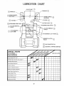
LUBRICATIONCHART
AXLE
(_
PIVOT
(_
SPINDLE
/
_ v--.......
BEARING
=_
....
SPINDLE
WHEEL
,_ :_,4._ -----------FRONT
BEARING
(_
N---L.
(_
(_
TIE ROD"I-'_"
STEERING
ROD
,.y
PIVOT.
r-=
.__
"'° "
"--"-"
TIE ROD (_
_
CLUTCH
PIVOT
STEERING
(_)
ROD PIVOT
(_)
CLUTCH/BRAKE
(_
PIVOT
_
CLUTCH/BRAKE
ATTACHMENTLIFT
ARM
/
PIVOT
#AT
ATTACHMENT
(_
LIFT ARM
MOWER CLUTCH
PIVOT
(_SAE
(_
SERVICE
OIL
PURPOSE GREASE
RECORD
FILL IN DATES
AS YOU COMPLETE
REGULAR SERVICE
SERVICE
Check Engine Oil Level
Change
(_
30 MOTOR
GENERAL
1_
Engine
Oil
DATES
_ItlP!
(see chart,
page 7)
...................
_
..............
LubricatePivot Points
Check
Brake
Operation
Clean Air Screen
Clean Air
V
Cleaner
i
Etement
_
......
ICfean
Engine
Cooling
I
Fins
Replace Spark
Plug ........
Check
Battery
Level
Check
Tire Pressure
•
....
-
'
.........
:
:=
....
!
..................
V
_j
I
'........................
_#
- 22 -
............
I...........I
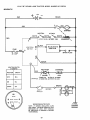
12 H.P° 38" RIDING
LAWN TRACTOR--MODEL
NUMBER
917o255741
SCHEMATIC;
RED
%
NEUTRAL
ATTACH
WHITE
WHITE
RED
INTER'K
IGNITION
SWITCH
O
STARTER
SW INTER'K
SW
SOLENOID %
%
SOLID STATE
IGNITION
(_
M
BLACK 7
B
SPARK PLUG
30 AMP
a
G
BLACK
IGNITION SWITCH
STD365402
RECTIFIER
CHARGING
RED
POSITION
CIRCUIT
OFF
M-G
ORANGE
ON
B*L
START
B_
(DIODE)
COIL
3 AMPS, DC 20 VOLTS, AC (MIN,)
AT 3600 RPM, BATTERY IN LINE
BROWN
LIGHT
SWITCH
BROWN
WIRING INSULATED CLIPS
NOTE: IF WIRING
INSULATED
CLIPS
AND CABLE TIESWERE REMOVED FOR
SERVICING
OF UNIT, THEY SHOULD
BE REPLACED TO PROPERLY SECURE
YOUR WIRING°
.23.
N
CHASSIS
GROUND
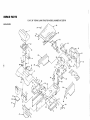
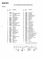
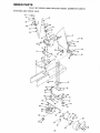
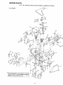
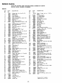
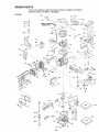
REPAHR PARTS
12 H.P. 38" RIDING
LAWN TRACTOR-MODEL
NUMBER
917.255741
ELECTRICAL
29
9
%
20
17
!1
18
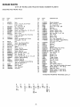
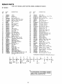
REPAIR
PARTS
12 H.P. 38" RIDING
LAWN TRACTOR--MODEL
NUMBER
917.255741
ELECTR ICAL
KEY
NO.
PART
NO.
!
2
3
4
5
6
7
8
9
10
11
12
13
14
t5
16
7662J
105386X
108865X
105613X
105381X
104445X
3258,1
11 t51000
STD365402
108824X
STD551125
STD541225
STD522505
73510400
108423X
11050400
DESCRIPTION
Bulb, L,ght
Harness, Light Socket
Harness, Ignition
Key Set
Switch, Light
Switch, Interlock
Nut, Hex 5/8-32
Washer, Lock, Int. Tooth, 5/8
Switch, Ignition
Fuse. 30 Amp.
*Washer, Lock, 1/4
*Nut, Hex Jam 1/4 - 20
*Bolt, Hex, 1/4 - 20 x 1/2 Gr. 5
Nut, Keps 1/4 - 20
Cable Assembtv
Washer Lock, Ext. Tooth, 1/4
KEY
NO.
PART
NO.
17
18
20
21
22
23
24
25
26
27
28
719J
5t14J
42073
STD522507
STD551025
STD541025
9272R
102476X
S_D541625
11030400
72240460
29
32
-----
2008J
7192J
101539X
109034X
*STANDARD
A
_)
B
12
13
DESCRIPTION
Cover, Termlnat
Cable,Battery
Cable, Battery
*Bolt, Hex, 1/4 - 20 x 3/4
*Washer 9/32 x 5t8 x t6 Ga.
*Nut, HEX 1/4 -20
Battery, 12V.. Sears
Terminal Guard
*Wing Nut 1/4 - 20
int,/Ext.
Tooth
Lockwasher
Battery Bolt (Bolt - Carriage,
Sqo Neck t/4 - 20 x 7 • 1/2)
Solenoid
Cable Tie
Sheet - Instruction,
Owners Manual
Tractor
HARDWARE--PURCHASE
1/4
Rd. Hd.
15 ° Slope
LOCALLY
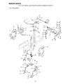
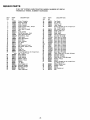
REPAIR
PARTS
12 H,P. 38" RIDING
LAWN TRACTOR--MODEL
NUMBER
917.255741
ENCLOSURE
49
54
33
35
29
52
L,
G_
21
37_
4O
55
G
29
20
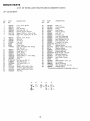
REPAIR
PARTS
'12 H.P. 38" RIDING
LAWN TRACTOR-MODEL
NUMBER
917.255741
ENCLOSURE
KEY
NO.
"M
PART
NO.
t
2
t08446X
17490612
3
17490616
4
5
6
7
8
9
10
1!
12
13
1055t3X
t05529X
73680500
105512X
105514X
105274X
19131312
STD523707
73680600
17490608
14
16
17
18
19
20
21
22
24
25
26
27
28
29
3O
31
32
105753X
105465X
105464X
STD533707
!05466X
108504X
108506X
108067X
108361X
I08360X
19131210
7603J
6999R
t05268X
105685X
108631X
105797X
DESCRIPTION
KEY
NO.
Seat
Screw, Hex Washer Thdo R_tl 3/816 x 3/4 Type TT
Screw, Hex Washer Thd, Rolling
3/8 - 16 x 1
Bracket- Pivot, Seat
Bolt. Shoulder, 5/16 - 18
Nut, Lock, 5/16 - 18
Spring * Compression
Clamp, Spring
Fender
Washer !3/32 x 13/16 x t2 Ga.
• Bolt, Hex, 3/8 - 16 x 3/4
Nut, Lock 3/8 - 16
Screw, Hex Washer Thd. Roll 3/8 16 x 1/2
Bracket. Fender
Footrest. L.H.
Footrest, R.H,
• Bolt, Carr, 3/8 - t6 x 3/4
Pad, Footrest
Bracket, Pivot, Grill, R.H.
Bracket, Pivot, Grill, L.H.
Pal Nut 1/4,20
Lens, L.H.
Lens, R.H.
Washer 13/32 x 3/4 x 10 Ga.,
Tray, Battery
Clamp - Hose
Bezel
Strap Assembly, Gril!
Decal, II
Hinge, Hood, L.H.
PART
NO.
33
34
35
36
37
38
39
40
41
42
48
49
50
51
52
53
54
55
56
59
60
61
63
64
65
66
67
68
69
70
71
72
DESCRIPTION
105792X
105682X
105678X
I08500X
I08501X
106927X
106929X
108967X
t02481X
108176X
105801X
105802X
105803X
!05806X
105807X
4900J
109165X
108428X
I05813X
10040600
19131212
STD523710
!06301X
106300X
106811X
106812X
106974X
19132012
106909X
106910X
106911X
105687X
Hinge, Hood, R.H.
Hood Assembly
Grill Assembly
Bracket, Frame, Pivot, R.H.
Bracket, Frame, Pivot, L,H,
Side Panel, R.H.
Side Panel, L.H.
Chassis Assembly
Drawbar
Pan - Seat
Decal- Reflective, Rear
Decal, Stripe, L.H.
Decal, Stripe. R.H.,
Decal, Grill Craftsman
Decal, Grill, Stripe
Deca!, Clutch/Brake
Decal, 12 H.P=
Decal, 6 Speed, 38"
Decal. V-Belt Schematic
Washer - Lock 3/8
Washer 13/32 x 3/4 x t2 Ga.
*Bolt, He× 3/8,16x
1
Guide - Belt, Lower, Eng. Pulley, L,H.
Guide - Belt, Lower, Eng. Pulley, R,H.
Decal • Stripe, Side Panel, L.H.
Decal _ Stripe. Side Panel, R.H.
Decal, OPEl, Caution
Washer 13/32 x 1 • 1/4 x 12 Ga,
Screw - Spema]
Washer
Clip
Tube - Plastic
*STANDARD
A
B
C
D
E
F
G
HARDWARE--PURCHASE
K
L
M
_:)
11_61
(_3
LOCALLY
N
O
22
_)6
@26
Qlz
070
@
12
@s9o1°
12
_61
_U 11
068
_12
@ 12
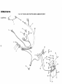
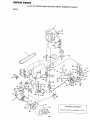
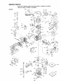
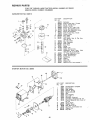
REPAIR
PARTS
12 H.P. 38" RIDING
LAWN TRACTOR--MODEL
NUMBER
917.255741
DRIVE
7O
=--58
_r_
'
16 61
OPTIONAL
Spark
Arrester
Screen
_59
90
EQUIPMENT
Assembly
677V1
61
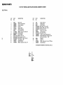
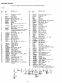
; EPAU$ PARTS
12 H.P. 38"
RIDING
LAWN
TRACTOR--MODEL
NUMBER
917.255741
:)RIVE
KEY
NO
PART
NO
108872X
2
3
4
5
6
0
1
13
105731X
9767H
STD551143
74770728
I05732X
10t200K
108835X
74030510
15
t7490632
16
17
19
19131316
2949R
108868X
20
21
22
23
24
25
26
27
28
STD523127
73680500
STD580025
t05703X
12000028
3723J
STD523710
2751R
17490512
30
31
32
33
34
35
36
37
38
39
40
41
42
43
44
45
46
47
48
108171X
109368X
4921H
106190X
STD523107
73680500
109370X
109369X
106360X
STD523707
19252616
106933X
105699X
19091210
106362X
STD561210
19151216
104777X
17490612
DESCRIPTION
KEY
NO.
Engine, t2 HP Model Nor
143-366202
Pulley, Engine
Valve, Drain Oil
*Washer, Lock, 7/t6
Bolt, Hex 7/16 - 20 x 1 - 3/4
V-Belt, Drive
Spacer - Engine
Muffler
Bolt, Filo Hd. Cross, Recess 5/I6 - 18 x
5/8
Screw, Hex Washer Thd Roiling
318 - 16 x 2
Washer 13/32 x 13/16 x 16 Gao
Gasket, Muffler
Transaxle, 6 Speed, Model No !43.920002 (See pages 36 and 37 for parts
breakdown)
*Bolt, Hex 5/16- 18 x 2- 3/4
Nut, Lock 5/16- 18
* Key, Woodruff
Pulley, Transaxle
Ring, Retainer
Bracket, Transaxte
*Bolt, Hex 3/8- 16 x t
Clip- Fuel Line
Screw, Hex Washer Thread Roiling
5/16- !8 x 3/4
Support, Battery
Keeper, Belt, L.H.
Retainer, Spring
Clamp
*Bolt, Hex 5/16 - 18 x 3/4
Nut, Lock 5/t6 - 18
Strap, Locator
Keeper, Belt, R.Ho
Strap, Torque, Transaxle
*Bolt, Hex 3/8- 16 x 3/4
Washer 25/32 x I - 5/8 x 16 Gao
Knob, Shift
Rod, Shift
Washer 9/32 x 3/4 x 10 Gao
Washer - Shift, Plate
*Cotter Pin, 1/8 x 1
Washer 15/32 x 3/4 x !6 Ga.
Retainer, Belt
Screw, Hex Washer Thd. Rolling 3/8 t6x 3/4
B
A
D
E
28
49
5O
51
52
53
54
55
56
57
58
59
60
61
62
63
64
65
• 66
67
68
69
7O
71
72
73
74
75
76
77
78
79
8O
81
82
83
88
89
90
91
92
93
96
97
98
99
100
101
102
t03
G
DESCRIPTION
19131312
Washer 13/32 x 13/16 x 12 Ga
I05730X
Keeper, Belt, Engine
106191X
Keeper, Belt
4470J
Spacer
4859J
Idler, Flat
106298X
Pulley, Idler
I05705X
Bellcrank Assembly (Inc. Key No 92)
STD523715 *Bolt, Hex 3/8- 16 x 1 - 1/2
I05709X
Spring, Return, Clutch
207J
Washer, Hardened
12000039
Ring, Klip
105710X
Link, Clutch
76020412
Pin, Cotter t/8 x 3/4
105724X
Bracket, Clutch
109127X
Rod, Brake
106888X
Spring, Rod, Brake
73350600
Nut - Jam 3/8 - 16
STD551t31
*Washer- Lock 5/16
105758X
Rod, Brake, Parking
71673
Cap - Plunger
t09037X
Shaft, Foot Pedal
8883R
Cover • Pedal
19252016
Washer 25/32 x t - 1/4 x 16 Ga
STD571810
*Pin, Rotlf 3/16 x 1
106918X
Arm, Brake
STD580025
* Key, Woodruff
STD580105
*Key, Square 3/16 x 2
104757X
Cap, Hub, Rear
59192
Cap, Valve
85 t39
Stem, Valve
106268X
Tire, Rear o 18 x 9.50 x 8
7152J
Tube, Tire {not furnished with tractor)
106108X
Rim Assembly, Rear
108870X
Spacer, Split
19252016
Washer 25/32 x 1 - 1/4 x 16Ga=
12000001
E-Ring
STD533707 *Bolt, Carriage 3/8 - 16 x 3/4
6404J
Spacer, Engine, Pulley
73680600
Nut, Lock 3/8.16
71040412
Bolt - Fin Hex 1/4 - 28 x 3/4
105706X
Bearing
106499X
Retainer- Belt
101326L
Deflector, Muffler
17210806
Screw, Hex Washer No. 8:- 32 x 3/8
13240300
Elbow ° Street
STD523727 *Bolt, Hex 3/8- 16 x 2 - 3/4
105700X
Spring- Torsion
I08843X
Plate, Shift
i
STD551!25
*Washer - Lock 1/4
STD551031 *Washer 11/32 X 11/16 x 16 Ga.
• STANDARD HARDWARE--PURCHASE
LOCALLY
H
J
L
N
P
Q
34
35
_
PART
NO
103
- 29 -
15
@,, @,,
_
66
_EPAaR PARTS
12 H,P, 38"
STEERING
AND
FRONT
RIDING
LAWN
TRACTOR--MODEL
NUMBER
917.255741
AXLE
,/--66
75
67
55
63
- 30-
,68
REPAaR PARTS
12 H.P, 38"
STEERING
KEY
NO
AND
,PAR T
NO
1
2
105620X
74180512
3
4
5
7
8
9
!1
73510500
105800X
108793X
17720408
108456X
105621X
17190508
12
13
108842X _
17490608
15
16
17
18
19
20
21
22
23
24
25
26
27
28
29
31
275tR
t05810X
t00710L
STD541350
100712K
1007!3N
100711L
105647X
!05643X
ST0523712
73680600
17431008
t05646X
1554J
102531X
17490612
32
33
34
35
6266H
108684X
106126X
12000029
FRONT
RIDING
LAWN
TRACTOR_-MODEL
NUMBER
917.255741
AXLE
DESCRIPTION
Dash
Screw .. Truss Hd, Cross Recess
5/16 .. t8 x 3/4
Nut- Keps 5/16- 18
Decal- Dash Panel
Control _Throttle
Screw., Hex Thread Cut 1/4 ..20 x 1/2
Decal _ Dash Lower
Dash - Lower
Screw .. Hex Washer Hd, Thread Cut
5/16 - 18 x !/2
Saddle
Screw- Hex Washer Hd. Thread
Rolling 3/8,16
x 1/2
Clip
Decal • Cap, Steering Wheel
Insert- Steering Wheel
*Nut- Hex Jam !/2 _20
Washer
Wheel- Steering
Adapter., Steering Wheel
Sleeve - Steering
Shaft - Steering,. Upper
*Bolt _,Hex 3/8,, 16x 1 - 1/4
Nut., Lock 3/8- 16
Screw -Hex Self Tap. No. 10 • 16 x 1/2
Bracket ,_Sleeve, Steering
Bushing- Steering
Bracket- Steering
Screw ,.Hex Washer Thread Rolling
3/8 _ 16 x 3/4 Type TT
Bearing- Thrust
Gear- Sector
Key -,Woodruff
Klip Ring
KEY
NO.
PART
NO
DESCRIPTION
36
37
38
39
40
41
42
43
44
45
46
47
48
49
10t930X
109068X
2882J
74580
71208
108683X
105663X
t05664X
74761060
105669X
105725X
t05726X
73901000
17490508
50
51
52
53
54
55
56
57
58
59
60
6t
62
63
64
65
66
--67
68
74
75
77
12000029
3366R
1057t5X
102792X
19131416
76020412
STD551137
STD541137
105727X
t05656X
I05654X
278H
9040H
106732X
59192
65139
106222X
59904
19252016
104757X
11150500
19252616
108685X
*STANDARD
A
C
D
®3
1,1
E
F
G
K
(_74
25
31
83
Washer Ha[dened
Shaft- Steering - Lower
Pin - Drive 3/16 x 1
Spacer _627 x. 88 x 695
Bushing
Rod - Steering
Support - Saddle - Rear
Support - Saddle - Front
Bolt- Hex 5/8- 11 x 3- 3/4
Axle - Front
Spacer - Axle
Bearing o Axle
Nut- Lock, Flange 5/8 - 11
Screw * Hex Washer Thread Rolling
5/t6 * t8 x 1/2 Type TT
Klip Ring
Bearing
Rod - Tie
Bushing
Washer 13/32 x 7/8 x 16 Ga.
Pin - Cotter 1/8 x 3/4
• Washer - Lock 3/8
• Nut - Hex 3/8- 24
Link - Drag
Spindle- L,H..
Spindle- R,,H,.
Fitting- Grease
Bearing- Flange
Rim - 6". Front
Cap - Valve
Stem - Valve
Tire- Rib 15 x 6.00- 6
Tube. Front (not furnished with tractor)
Washer 25/32 x 1 _ 1/4 x 16 Ga,
Cap o Hub - Front
Washer, Lock, lnt. Tooth 5/16
Washer 25/32 x I - 5/8 x 16 Gao
Gear, Pinion
HARDWARE,-PURCHASE
LOCALLY
REPAIIR
PARTS
12 HoP. 38"
RIDING
LAWN
TRACTOR-.MODEL
NUMBER
917,255741,
LIFT ADJUSTMENT
25
9
2O
C
41
34
4O
22
A
A
- 32 -
5!
REPAIR PARTS
12 H.P. 38"
LIFT
KEY
NO
RIDING
LAWN
TRACTOR--MODEL
NUMBER
917.255741
ADJUSTMENT
PART
NO
1
2
3
4
5
6
7
t06448X
106932X
I0645tX
73680600
!06452X
19171713
1702 t008
8
9
t0
tt
!2
t3
14
106447X
105965X
t05738X
101335K
9151R
6999R
174906t2
15
20
21
22
23
24
25
26
27
28
29
30
3t
32
33
t0690tX
106920X
105505X
10692 ! X
19292016
12000029
t00734K
STD541237
105686X
76020308
2876H
19131016
10t272K
19151216
12000037
DESCRIPTION
Lever. Clutch, Mower
Knob
Bolt, Shoulder
Nut, Lock. 3/8 • t6
Bracket, Switch, Interlock
Washer 17/32 x t • t/16x t3Ga,
Screw, Hex, Tapping, No 10 _24 x
1/2
Support, Lever. Clutch
Cap, Fuel
Tank. Fuet
Line. Fuel
Grommet
Clamp, Hose
Screw, Hex Washer Thd RolIing
3/8- 16 x 3/4
Clamp, Tank, Fuel
Panel, Dash, L.H
Cover, Access
Panel, Dash, R H
Washer 29/32 x 1 .. 1/4 x 16 Gao
Klip Ring
Knob
*Nut, Hex .Jam 3/8- 16
Rod, Adjust, Lift
Pin, Cotter 3/32 x t/2
Spring
Washer t3/32 x 5/8 x 16 Ga
Trunnion, Depth Adjustment
W3sher 15/32 x 3/4 x 16Ga
Klip Ring
A
B
C
KEY
NO
PART
NO
34
35
36
38
39
40
41
42
43
44
45
46
47
48
49
50
51
52
53
54
55
57
59
6t
62
63
64
66
105754X
Shaft, Lift
105768X
Lever, Assembly
105723X
Plunger
t06019X
Grip, Handle
4939M
Retainer, Spring
!05856X
Link, Lift
106204X
Trunnion, Lift
105855X
Link, Lift, Adjustable
105862X
Arm, Suspension, R H.
t05848X
Bolt, Shoulder, 3/8., t6
I05863X
Arm, Suspension, L, H
106308X
Trunnion, Lift, Lower
STD541250 *Nut, Hex, 1/2- 13
9135R
Retainer, Spring
19171416
Washer 17/32 x 7/8 x 16 Ga
4921 H
Retainer, Spring
!05864X
Bracket, Suspension
106444X
Bracket, Beticrank
STD523707
"Bolt, Hex 3/8 - 16 x 3/4
10644 tX
Bettcrank Assembly
76020412
Pin, Cotter, 1/8 x 3/4
106446X
Rod, Clutch, Primary
5320R
Clip
I05764X
Rod Assembly - Lever, Lift
105767X
Pin- Groove
t06810X
Spring- Extension
72140606
Bolt, Carriage 3/8- 16 x 3/4
108236X
Bracket, Switci_
*STANDARD
HARDWARE-.PURCHASE
LOCALLY
D
E
_44
_53
®4®4
- 33 -
DESCRIPTION
12H,P,38" RIDINGLAWNTRACTOR--MODEL
NUMBER917.255741
38" MOWER
-"--
t
CC
22
A
55
I
56
12
tB
I3
68
?
56
_61
H
H
E
J
7
H
_llFF-- REAR BAGGER
ATTACHMENT
I USED, REFER TO REAR BAGGER
[MANUAL FOR BLADE PART NOo
IS BEING
OWNERS
41 42
34 -
E
RSPAUR PARTS
12 H.P. 38" RIDING
38"
LAWN TRACTOR--MODEL
NUMBER
917.255741
MOWER
KEY
NO
PART
NQ
DESCRIPTION
t
2
3
4
5
6
7
8
9
10
1t
t2
13
t4
15
17
t8
19
20
21
22
23
24
25
26
27
28
29
30
3!
32
33
34
35
36
37
38
106085X
105689X
8417J
73680600
t9111216
72140505
105896X
5846R
106734X
106735X
106736X
t05814X
105304X
105662X
105744X
105872X
105743X
STD523707
73680500
105659X
105660X
STD533107
37133
106295X
t05850X
t 06975X
106461X
STD523720
108832X
106902X
102403X
106513X
102669X
105891X
100668L
17490612
17490620
V-Belt
Housing
Runner, R H
Nut, Lock, 3/8. 16
Washer, 11/32 x 3/4 x 16 Ga
Bolt, Cart, 5/16- 18 x 5/8
Bracket, Deflector
Nut
Spring, Deflector
Rod oHinge
Deflector ..Shield
Decal
Cap
Link, Parallet
Pin - Hinge, Front
Stop, Link
Pin - Hinge, Rear
*Bolt 3/8 _.16 x 3/4
Nut, Lock 5/16. 18
Bracket, Lift, RH
Bracket, Lift, LH.
*Bolt, Cam 5/16. 18 x 3/4
Instruction - Caution Decal
Support, Arm
Stop, Deck, Front
Decal - Safety Standard
Guide, Belt
*Bolt 3/8 ,. 16 x 2"
Arm, idler
Spacer
Pulley, Idler
Washer, Wear, !/16
Keeper, Belt
Mandrel Assembly
Plate, Support, Mandrel
Screw, Hex Washer Hd, 3/8- 16 x 3/4
Screw, Hex Washer Hd_ 3/8- t6
x1_1/4
A
B
C
D
E
DESCRfPTION
39
40
41
42
43
44
45
46
47
48
49
50
52
53
54
55
56
57
58
59
60
61
62
63
64
65
66
67
68
69
70
71
72
73
74
75
-76
t06634X
19132012
ST[355_ 137
STD623715
108250X
108235X
4921H
STD560907
108068X
76020616
108247X
STD533707
108243X
10824tX
105857X
108673X
106578X
106463X
108249X
106456X
I00672K
100673L
1065!4X
19111016
74760684
763tj
19131614
72140610
78850
19141614
STD551037
19141610
72110606
19132012
106679X
76020308
72110506
F
G
H
J
Blade, 38"
Washer 13/32 x ! . 1/4 x 12 Ga
*Washer, Lock, 3"8"
"Bolt. Hex. 3i8-24x
1 . ! 2Gr 5
Spring, Ext
Rod ,.Clutch, Mo_er
Spring, Reta:ne_
*Pin., Cotter. 3 32 x 3 4
Rock Shaft Assembl /
Pin, Cotter. 3/16 x !
Rod. Brake, Prlmary
"Bolt. Cart. 3/8 _.16 x 3 4
Bracket, Pivot. RH
Bracket, Pivot, L H
Bracket, Susp. Rear. R H
Bracket, Susp:, Rear, L H
Brake Assembly
Rod, Brake, Secondary LH
Rod, Brake, Secondary, R H
Bracket. Brake, Pivot
Spacer, Brake
Bracket, Support
Washer, Wear 3 16
Washer, 11/32 x 5/8 x 16 Ga
Bolt, 3/8- 16 x 5- 1/4
Runner, L H.
Washer 13/32 x 1 x 14 Ga,
Bolt, Carr 38. 16x 1 , 1 4
Decal ..Warning
Washer 7 16 x I x 14 Ga:
"Washer 13 32 x 13 t6 x !6 Ga
Washer 7 t6 x 1 x 10 Ga.
Bolt, Cart;age 3 8 .. 16 x 3 4
Washer13 32 x t.,14x12Ga
Decal ,,Warning
Pin. Cotter 3 32 x 1 2
Bolt, Carriafle 5 16,118x3
4
HARDWARE,,,PURCHASE
K
L
LOCALLY
M
N
,
_
64
@ 71
_20
20
PART
NO
*STANDARD
If2
_5
KEY
NO
_
4
_4
© 20
_20
84
@4
IF REAR BAGGER ATTACHMENT
IS BEING
|USED,
REFER TO REAR BAGGER OWNERS
MANUAL
- 35_
FOR BLADE PART NO,
U
67
REPAIR
PARTS
12 H.P. 38" RIDING
TRANSAXLE--MODEL
75
NUMBER
917.255741
10
35
/
LAWN TRACTOR--MODEL
NUMBER 143.920-002
8
31
29
29 _(_-
_ 32
6
62
35
<f
34
_f18
_
60
30
51
30
52
30
69
11
30 53A
/
34
26
29
.\
48
\
37
41
- 36-
67
REPAIR
PARTS;
12 H.P. 38" RIDING
TRANSAXLE--MODEL
KEY
NO.
PART
NO,.
1
2
3
4
5
6
7
8
9
10
11
12
13
14
15
16
17
18
2O
21
22
23
24
25
772094
780086
770082
776260
776219
778139
778136
792123
784216 _
784337
778188
778113A
778221
778068
778165
786101
786040
786110
792077
792078
792079
788061
788062
792073
t;_E,
792018
792035
788040
780072
780108
780001
792001
788051
780105A
7801!8A
790003
790007
26
27
28
29
3O
31
32
33
34
35
36
37
LAWN TRACTOR_-MODEL
NUMBER
143o920-002
DESCRIPTION
Cover, Transaxle
Bearing, Needle
Case, Transaxle
Shaft, Counter
Shaft Et Pinion Assy,, Output
Gear, Output
Gear, Spur (15 teeth)
Key
Collar, Shifter
Rod _ Fork Assy, Shift
Gear, Bevel (42 teeth)
Bevel Pinion, Input
Gear, Bevel
Gear, Bevel pinion
Gear, Ring
Block, Bearing
Pin, Drive
Spacer
Bail, Steel (5116" dia.)
Set Screw, 3/8-16 x 3/8
Spring
Ring, Felt
Packing, Felt
Screw, Flanged hex hd. thread forming, 1/4-20 x 1-1/4
Ring, Retainer
Ring, Retainer
Ring, Retainer
Washer, Thrust
Washer, Thrust
Washer
"O" Ring
Seal, Square cut
Bushing, Flanged
Bushing, Flanged
Disk, Brake
Plate, Brake pad
- 37
NUMBER
KEY
NO,
PART
NO,
38
39
40
41
42
790006
786026
792076
790038
792073
43
44
45
46
47
48
49
50
51
52
53
53A
54
55
56
57
58
59
60
61
62
64
65
66
67
792075
790025
776259
776135
774690
774691
778t46A
778125
778124A
778123A
778122A
778209
778211
778151
778126A
778127A
778128A
778163
786081
786082
786107
792074
780109
786067
792085
68
69
70
71
75
786086
780051
786118
788069
786116
917.255741
DESCRIPTION
Pad, Brake
Pin, Dowel
Washer, Flat
Lever, Brake
Screw, Flanged hex hd. thread forming, 1/4-20 x 1-1/4
Nut, Lock, 5/16-24
Holder, Brake pad
Shaft, Brake
Shaft, Input
Axle (11-t5/16
long)
Axle (16-1/2"
long)
Gear, Spur (37 teeth)
Gear, Spur (35 teeth)
Gear, Spur {30 teeth)
Gear, Spur (25 teeth)
Gear, Spur (22 teeth)
Gear, Spur (19 teeth)
Gear, Spur (12 teeth)
Gear, Spur (t5 teeth)
Gear, Spur (20 teeth)
Gear, Spur {25 teeth)
Gear, Spur (28 teeth)
Gear, Spur (31 teeth)
Chain, Roller (No, 41 chain, 24 links)
Sprocket (9 teeth)
Sprocket
(18 teeth)
Ptug, Hex hd,, 9/t6-18
thread
Washer, "Fhrust
Spacer
Screw,
Flanged hex hd, thread forming 1/4_20 x 2-1/4
Bracket, Brake lever
Washer, Thrust
Spacer
Seal, Square cut
Disk
R_PAIR
PARTS
12 H.P. 38" RIDING LAWN TRACTOR--MODEL
ENGINE-+MODEL
NUMBER 143,366202
NUMBER
917.255741
ENGINE
13
58
62
,,.,,..
- 38 +
82
REPAIR
PARTS
12 H.P. 38" RIDING LAWN "I-RACTOR°-MODEL
ENGINE--MODEL
NUMBER 143.366202
NUMBER
917o255741
ENGINE
KEY
NO.
PART
NO.
DESCRIPTION
KEY
NO°
1
2
3
4
5
6
7
8
9
10
35323
28277
35324
32651
29916
650548
35203
35319
35326
650561
65
11
12
13
14
15
16
17
18
19
2O
21
22
23
24
25
35336
35327
27652
29826
29216
29918
303_
29642
35329
34866
31919
35330
650882
35313
35314
26
27
28
28A
29
30
35315
35316
650128
30688
"35317
35318
31
32
33
34
35
36
37
38
39
4O
31356
31927
35319
35320
31707A
30590A
35321
35322
29193
650833
41
42
43
44
45
45A
46
47
49
5O
51
52
53
54
55
56
57
58
59
32589
611093
650880
650881
35135
610118
650872
650814
"35306
35307
730218
34315
35308
35309
650691
650690
650746
650692
34046
6O
6OA
6t
62
63
64
t'33481
t'35358
33480
35310
t" 33484
650168
Cylinder Assy (Inct Nos 8 _ 13)
Washer, Flat
Rod, Governor
Lever, Governor
Clamp. Throttle lever
Screw. Hex washer hd, 8-32 x 5/16
Spring, Control
Seal, Oil
Baffte, Blower housing
Screw, Hex washer hd Dudok, !/4-20
x 5/8
Crankshaft Assy, (Counterbalance)
Gear, Counterbalance
Pin, Dowel
Screw, Hex washer hd, 10-32 x 3/4
Nut, Lock
Washer, E T_ Lock
Nut 8- Washer, 10-32 "Keps"
Ring, Retaining
Piston _ Pin Assy (Std.) (Incl. No. 21)
Ring Set, Piston (Std,)
Ring, Piston pin retaining
Rod Assy, Connecting (tncl. No 23)
Screw, Connecting rod
Lifter, Valve
Camshaft Assy (Mech, Compression
Release)
Weight Assy., Counterbalance
Extension, Blower housing
Screw, Fit hd Seres, 10_24x I/2
Screw, Hex hd, Sems, 1/4-20 x 1/2
Gasket, Mounting flange
Flange, Mounting (Inct. Nos, 32, 33 _t
34)
Pump Assy,, Oil
Plug, Oil drain
Seal, Oil
Shaft, Governor
Spacer, Governor gear (tncl No. 36)
Washer, Flat
Gear Assy,, Governor
Spool, Governor
Ring, Retaining
Screw, Hex washer hd. Powerlok,
1/4-20 x 1-3/16
Key, Flywheel
Flywheel (3 Amp, w/ring gear)
Washer, Lock
Nut, Flywheel
Solid State Assy. (Incl No 45A)
Cover, Spark plug
Stud, Solid State Assy
Screw, Hex hd Seres, 10-24 x I
Gasket, Cylinder head
Head Assy, Cylinder
Valve Guide Kit (tncf 2 of No 52)
Ring, Retaining
Valve, Exhaust (Std.)
Valve, Intake (Std)
Washer, Fiat
Washer, Be[levilie
Screw, Hex hd, 5/16-18 x 3/8
Screw, Hex hd,, 5/16-18 x !-3/4
Resistor Spark Plug (Champion RL86C or equivalent}
"O" Ring
"0" Ring
Tube, Push rod
Housing, Rocker arm
"0" Ring
Washer, Flat
66
67
68
69
70
7t
72
73
74
75
76
77
78
79
80
PART
NO.
32610A
t'33509
t'344!0
33510
33507
33508
t'35295
35296
650878
35297
35298
28264
33471
1"'35299
35300
t'65O879
82
83
84
85
86
87
88
89
90
91
92
93
94
"27896
28423
28424
28425
35350
650128
35301
650128
650517
"33263
35304
35302
34109A
94A
94B
94C
96
31342
650549
35346
30200
97
98
99
100
101
102
103
792028
*33515
35288
650738
35338
30688
297478
t04
105
111
115
115A
116
1t8
119
119A
120
121
35290
650273
30668
35411
125
126
127
128
129
130
131
131A
33992A
33589A
33590
34909
35108
34910
650875
35437
34113
29774
26460
34279A
27793
28942
DESCRIPTION
Screw,
Flanged
hex
hd,
x
"O" Ring (Intake)
"0" Ring (Exhaust)
Cap, Valve spring
Spring, Valve
Cap, Valve spring keeper
"O" Ring
Guide, Push rod
Stud, Rocker arm
Arm, Rocker
Bearing, Rocker arm
Nut, Lock
Rod, Push
"0"
Ring
Cover, Rocker arm housing
Screw,
Pan
hd,
w/seating
Lockwasher,
8-32 x 1t2
Gasket, Valve cover
Body, Breather
Element, Breather
Cover, Valve spring box
Tube, Breather
Screw, Fil hd, Sems, 10-24 x 1/2
Extension,
Blower housing
Screw, Fil, hal, Seres, 10-24 x 1/2
Screw,
Fil, flex hd,, 1/4-20 x 7/8
Gasket, Carburetor
to intake pipe
Pipe, Intake
Link, Governor
Bracket Assy,, Contro_ (Incl. Nos, 94A
Et 94B)
Spring, Compression
Screw, Fil., hd, 5-40 x 7t16
Link, Governor spring
Screw, Hex washer hd.. setf4ap Sems,
10-24 x 9/16
Screw, Hex hd. Seres, 5/16-18 x 7/8
.
Gasket, Intake pipe
Brace, Intake pipe
Screw,
Hex washer
spinlock
hd.
thread forming,
t/4-20 x 5t8
Housing,
Blower
Screw, Hex hd, Sems, 1/4-20 x 1t2
Screw, Phil, Hex hd, Sems, 5/t6-24 x
21 t32
Cover, Cylinder head
Screw, FiL hd, Sems, 5/16-18 x 1/2
Screw, Hex hd_ Seres, 1/4-20 x 1t2
Ssreen, Starter
Pop, Rivet (Can be purchased locally)
Plug, Blower housing
Line, Fuel
Clamp, Fuel line
Filter, Fuel (tnci No o 119)
Clip, Conduit
Screw, Hex washer hdo Sems, t0-32 x
3/8
Tube, Oil fill
Dipstick,
Oi_ (Incl, No, 127)
"O" R_ng
Body, Air cleaner
Fiiter, Fe_t air cleaner
Filter, Air cleaner
Screw, Fil hd Seres, 10o32 x 5-1/4
Clip
*Indicates
Part_, !,_cluded in
Gasket Set Key No 174
- 39 -
1/4-20
29/32
REPAIR
PAR TS
12 H.P. 38" RIDING LAWN TRACTOR--MODEL
ENGINE-oMODEL
NUMBER 143,366202
ENGINE
40 -
NUMBER
917.255741
REPAIR
PARTS
12 H.P. 38" RIDING LAWN TRACTOR--MODEL
ENGINE--MODEL
NUMBER 143,366202
NUMBER
917.255741
ENGINE
KEY
NOo
PART
NO.,
DESCRIPTION
KEY
NO,
PART
NO,
DESCRIPTION
132
133
!34
135
'33629
*34912
35286
650784
136
137
34911
611096
169
t70
170B
t71
173
174
t75
30688
34346
34387
632413
33605
35331
35332
Screw, Hex hd. Sems, t/4-20 x 112
Decal, instruction
Decal, Instruction
Carburetor
(Inct No, 91t
Motor, Electric starter
Gasket Set (Incl items marked ")
"O" Ring Kit (lnd
items marked tt
137A
138
!39
140
143
650873
610935
610921
610922
33997
Gasket, Air cleaner elbow
Gasket, Air cleaner to housing
Adapter,
Air cteaner
Screw, Hex hd. taptite, w!flatwasher,
t0-24 x tl/16
Cover, Air cleaner
Coil Assy,,
Alternator
(3 Amp DC)
{Inct, Nos. t38, 139 8- 140)
Screw, Hex hd Sems, t/4-20 x 3/4
Diode
Connector
Body
Female Terminal
Clip, Oil fill tube
"indicates Pans Included in
Gasket Set Key No 174
t Indicates Parts Included in
"O" Ring Kit, Key No. 175,
- 41 -
$111PAIII PAIIT$
12 H.P. 38" RIDING
LAWN
ENGINE--MODEL
NUMBER
CARBURETOR
TRACTOR-MODEL
143.366202
NUMBER
917.255741
NO. 632413
DESCRIPTION
1 _...4_
7
-_" /_
t
2-._
, -" _
i
'___17
27--,,.,_
29 _=_
26""
e_".z",''_(_
5 3__j_).__.
___
@
_:_f
4
6
_
to
"°
..
;_
_
I _
_ 14-
','
650506
6
650417
9
10
11
12
632248
"630748
"63!027
13
14
15
16
17
18
21
22
631022
632019
*631024
*631867
632247
631183
27110
*632239
3t
23
630740
/
24
25
*632281
*631028
. _16
,
,
t
I
I
/
&.
/
_4.-'_
""--..
MOTOR
_631021
27
631184
26631775
30
29
31
STARTER
Carburetor
Shaft Ef Lever Assy., Throttle
Spring, Throttle return
Shutter, Throttle
Screw, Rd hd, 4-40 x 3/16
Spring, Idle regulating screw
Spring, Main adjustment
screw
Screw, idle regulating
Shaft _ Lever Assy,
Choke
Shutter, Choke
Plug, Welch
Plug, Welch
Inlet Needle,
Seat 8 Clip Assy.
(fnc!. No. 13)
Clip, Inlet needle
Float, Carburetor
Shaft, Float
Bowl, Float
Spring
Washer, Felt
Gasket, Bowl-to-body
Main
Adjustment
Screw
Assy.,
(Incl Nos, 5A, 21, 23 8 30)
"0" Ring, Adjustment
screw
Screw, Idle adjustment
Gasket, Bowl-to-body
Fuel Fitting
Washer
Seal, Dust
Washer, Flat
Repair Kit find
items marked *)
35A630766
63224 630738
_
,
i
t
NO..
PART
632413
632243
632244
4
5
/
,
r
',
_Y"<,, 5 30*'"_L.);
i
11
_ ,
24
, I
"_
@.
_
,
..
15
NO
KEY
1
2
630739
631971
632347
NO, 33605
11
18
12
13
10
j
8
1
2
6
KEY
NO.
PART
NO.
DESCRIPTION
1
2
3
4
5
6
7
8
11
12
33605
33451
33842
33430
33431
33432
33433
33450
33434
33712
33705
13
14
15
16
17
18
33440
590500
33449
33706
650168
650723
Starting Motor, Complete
Cover, Dust
Ring, Retainer
Retainer, Spring
Spring, Anti-drift
Gear
Nut, Engaging
Nut, Lock
Cap Assy., Drive end
Card Assy.., Brush (IncL No. 12)
Brush 8" Spring Kit {Inclo 4 pcs.. of
No. 13)
Spring, Brush
Washer, Thrust
Bolt, 10-32 x 4-1/4
Cap Assyo, Commutator
end
Washer, Flat
Nut, Hex
SUGGESTED
GUIDE
FOR SUGHTING
SLOPES
FOR SAFE
ONLY
NOT
SIGHTING
RiDE
SIGHT AND HOLD THiS
SKY LINE OR TREE
t5 °
LEVEL
WiTH
MAX.
Operate
greater
ally to
your Tractor
up and down the face of slopes (not
than 15°); never across the face. Make turns graduprevent
tipping
or loss of control.
Exermse extreme
caution
when
changing
direction
on slopes.
UP AND
ACROSS
.GUIDE
OPERATUON
HILL
DOWN
HiLL
12 H.P.
38" RID JNG
LAWN TRACTOR
ELECTRIC START
OWNERS
MANUAL
MODEL
NO.
The Model Number will be found on the Model Plate attached
to the Fender,, Always mention
the Model Number when
requesting service or parts for' your Lawn Tractor.
917.255741
Al! parts listed herein may be ordered from any Sears Service
Center/Departments
and most Sears Retail Stores.
WHEN ORDERING
REPAIR
FOLLOWING
INFORMATION:
HOW TO ORDER
REPAIR PARTS
®
•
®
O
THE
THE
THE
THE
PARTS,
ALWAYS
GIVE
THE
PART NUMBER
PART DESCRIPTION
MODEL NUMBER
NAME OF MERCHANDISE
If the parts you need are not stocked locally, your order will
be electronically transmitted
to a Sears Repair Parts Distribution Center for "expedited handling".
Sears, Roebuck and Co., Chicago, IL 60684 U,S.A.