1
INVERTER
M4000E
M4000E
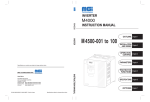
INSTRUCTION MANUAL
INVERTER
M4500E-001 to 010
OUTLINE Chapter 1
INSTALLATION Chapter 2
AND WIRING
OPERATION/ Chapter 3
CONTROL
PARAMETERS Chapter 4
Specifications and contents are subject to change without notice.
MGI TECHNOLOGIES INC.
275 West 4th Avenue
Vancouver, British Columbia
Canada V7N 3B1
Toll Free Tel: (877) 539-2542 (Canada&USA)
Toll Free Fax: (800) 539-2542 (Canada&USA)
Internet :
www.mgitech.com
IB(NA) 0600222ENG-A (0412) MEE Printed in Japan Specifications subject to change without notice.
INSTRUCTION MANUAL
Head Office:
PROTECTIVE Chapter 5
FUNCTIONS
MAINTENANCE/ Chapter 6
INSPECTION
SPECIFICATONS Chapter 7
M4500E.book 1 ページ
2005年2月22日 火曜日 午後5時7分
Thank you for choosing the MGI inverter.
This instruction manual gives handling information and precautions for use of this
equipment.
Incorrect handling might cause an unexpected fault. Before using the inverter, please
read this manual carefully to use the equipment to its optimum.
Please forward this manual to the end user.
This instruction manual uses the International System of Units (SI). The measuring units
in the yard and pound system are indicated in parentheses as reference values.
This section is specifically about safety matters
Do not attempt to install, operate, maintain or inspect the inverter until you have read
through this instruction manual and appended documents carefully and can use the
equipment correctly.
Do not use the inverter until you have a full knowledge of the equipment, safety
information and instructions.
In this manual, the safety instruction levels are classified into "WARNING" and
"CAUTION".
WARNING
CAUTION
Assumes that incorrect handling may cause hazardous
conditions, resulting in death or severe injury.
Assumes that incorrect handling may cause
hazardous conditions, resulting in medium or slight
injury, or may cause physical damage only.
Note that even the
CAUTION level may lead to a serious consequence
according to conditions. Please follow the instructions of both levels because they are
important to personnel safety.
A-1
M4500E.book 2 ページ
2005年2月22日 火曜日 午後5時7分
SAFETY INSTRUCTIONS
1. Electric Shock Prevention
WARNING
While power is on or when the inverter is running, do not open the front cover.
You may get an electric shock.
Do not run the inverter with the front cover or wiring cover removed. Otherwise,
you may access the exposed high-voltage terminals or the charging part of the
circuitry and get an electric shock.
If power is off, do not remove the front cover except for wiring or periodic
inspection. You may access the charged inverter circuits and get an electric shock.
Before starting wiring or inspection, check to make sure that the inverter power
indicator lamp is off, wait for at least 10 minutes after the power supply has been
switched off, and check that there are no residual voltage using a tester or the
like. The capacitor is charged with high voltage for some time after power off and
it is dangerous.
This inverter must be grounded. Grounding must conform to the requirements of
national and local safety regulations and electrical codes. (JIS, NEC section 250,
IEC 536 class 1 and other applicable standards)
Any person who is involved in the wiring or inspection of this equipment should
be fully competent to do the work.
Always install the inverter before wiring. Otherwise, you may get an electric
shock or be injured.
Operate the switches and potentiometers with dry hands to prevent an electric
shock.
Do not subject the cables to scratches, excessive stress, heavy loads or
pinching. Otherwise, you may get an electric shock.
Do not change the cooling fan while power is on.
It is dangerous to change the cooling fan while power is on.
2. Fire Prevention
CAUTION
Mount the inverter and brake resistor on an incombustible surface. Installing the
inverter directly on or near a combustible surface could lead to a fire.
If the inverter has become faulty, switch off the inverter power. A continuous flow
of large current could cause a fire.
When a brake resistor is used, use an alarm signal to switch power off.
Otherwise, the brake resistor may excessively overheat due to damage of the
brake transistor and such, causing a fire.
Do not connect a resistor directly to the DC terminals P(+), N(-). This could cause
a fire.
A-2
M4500E.book 3 ページ
2005年2月22日 火曜日 午後5時7分
3. Injury Prevention
CAUTION
Apply only the voltage specified in the instruction manual to each terminal to
prevent damage etc.
Ensure that the cables are connected to the correct terminals. Otherwise,
damage etc. may occur.
Always make sure that polarity is correct to prevent damage etc.
While power is on and for some time after power-off, do not touch the inverter or
brake resistor as they are hot and you may get burnt.
4. Additional Instructions
Also note the following points to prevent an accidental failure, injury, electric shock, etc.
(1) Transportation and installation
CAUTION
When carrying products, use correct lifting gear to prevent injury.
Do not stack the inverter boxes higher than the number recommended.
Ensure that installation position and material can withstand the weight of the
inverter. Install according to the information in the Instruction Manual.
Do not operate if the inverter is damaged or has parts missing.
Do not hold the inverter by the front cover or operation panel; it may fall off.
Do not stand or rest heavy objects on the inverter.
Check the inverter mounting orientation is correct.
Prevent screws, wire fragments or other conductive bodies or oil or other
flammable substance from entering the inverter.
Do not drop the inverter, or subject it to impact.
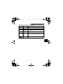
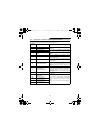
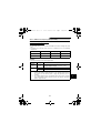
Use the inverter under the following environmental conditions:
Environment
Ambient
temperature
-10°C to +40°C (14°F to 104°F) (non-freezing)
Ambient humidity
90%RH or less (non-condensing)
Storage
temperature
-20°C to +65°C * (-4°F to 149°F)
Ambience
Indoors (free from corrosive gas, flammable gas, oil mist, dust
and dirt)
Altitude, vibration
Maximum 1000m (3280.80 feet) above sea level for standard
operation. After that derate by 3% for every extra 500m
(1640.40 feet) up to 2500m (8202.00 feet) (91%).
5.9m/s2 or less (conforming to JIS C 60068-2-6)
*Temperatures applicable for a short time, e.g. in transit.
A-3
M4500E.book 4 ページ
2005年2月22日 火曜日 午後5時7分
(2) Wiring
CAUTION
Do not fit capacitive equipment such as power factor correction capacitor,
capacitor type filter or surge suppressor to the output of the inverter.
The connection orientation of the output cables U, V, W to the motor will affect the
direction of rotation of the motor.
(3) Trial run
CAUTION
Check all parameters, and ensure that the machine will not be damaged by a
sudden start-up.
(4) Operation
WARNING
When you have chosen the retry function, stay away from the equipment as it will
restart suddenly after an alarm stop.
The [STOP] key is valid only when the appropriate function setting has been
made. Prepare an emergency stop switch separately.
Make sure that the start signal is off before resetting the inverter alarm. A failure
to do so may restart the motor suddenly.
The load used should be a three-phase induction motor only. Connection of any
other electrical equipment to the inverter output may damage the equipment.
Do not modify the equipment.
Do not perform parts removal which is not instructed in this manual. Doing so
may lead to fault or damage of the inverter.
A-4
M4500E.book 5 ページ
2005年2月22日 火曜日 午後5時7分
CAUTION
The electronic thermal reray function does not guarantee protection of the motor
from overheating.
Do not use a magnetic contactor on the inverter input for frequent starting/
stopping of the inverter.
Use a noise filter to reduce the effect of electromagnetic interference. Otherwise
nearby electronic equipment may be affected.
Take measures to suppress harmonics. Otherwise power supply harmonics from
the inverter may heat/damage the power capacitor and generator.
When a 400V class motor is inverter-driven, it should be insulation-enhanced or
surge voltages suppressed. Surge voltages attributable to the wiring constants
may occur at the motor terminals, deteriorating the insulation of the motor.
When parameter clear or all clear is performed, each parameter returns to the
factory setting. Re-set the required parameters before starting operation.
The inverter can be easily set for high-speed operation. Before changing its
setting, fully examine the performances of the motor and machine.
In addition to the inverter's holding function, install a holding device to ensure
safety.
Before running an inverter which had been stored for a long period, always
perform inspection and test operation.
(5) Emergency stop
CAUTION
Provide a safety backup such as an emergency brake which will prevent the
machine and equipment from hazardous conditions if the inverter fails.
When the breaker on the inverter primary side trips, check for the wiring fault
(short circuit), damage to internal parts of the inverter, etc. Identify the cause of
the trip, then remove the cause and power on the breaker.
When any protective function is activated, take the corrective appropriate action,
then reset the inverter, and resume operation.
(6) Maintenance, inspection and parts replacement
CAUTION
Do not carry out a megger (insulation resistance) test on the control circuit of the
inverter.
(7) Disposing of the inverter
Treat as industrial waste.
CAUTION
(8) General instructions
Many of the diagrams and drawings in this instruction manual show the inverter
without a cover, or partially open. Never operate the inverter in this manner. Always
replace the cover and follow this instruction manual when operating the inverter.
A-5
M4500E.book I ページ
2005年2月22日 火曜日 午後5時7分
CONTENTS
CHAPTER 1
OUTLINE
1
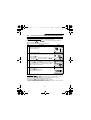
1.1 Pre-Operation Information..................................................................................... 2
1.1.1 Precautions for operation .................................................................................. 2
1.2 Basic Configuration ............................................................................................... 4
1.2.1 Basic configuration ............................................................................................ 4
1.3 Structure ................................................................................................................. 5
1.3.1
1.3.2
1.3.3
1.3.4
1.3.5
1.3.6
1.3.7
Appearance and structure ................................................................................. 5
Removal and reinstallation of the front cover .................................................... 6
Removal and reinstallation of the wiring cover .................................................. 7
Removal and reinstallation of the accessory cover ........................................... 8
Reinstallation and removal of the operation panel ............................................ 9
Removal of the operation panel (FR-PA02-02) front cover ............................. 10
Exploded view ................................................................................................. 11
CHAPTER 2
INSTALLATION AND WIRING
13
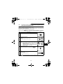
2.1 Installation ............................................................................................................ 14
2.1.1 Instructions for installation ............................................................................... 14
2.2 Wiring .................................................................................................................... 16
2.2.1 Terminal connection diagram .......................................................................... 16
2.2.2 Wiring of the Main Circuit ................................................................................ 20
2.2.3 Wiring of the control circuit .............................................................................. 23
2.2.4 Connection to the PU connector...................................................................... 28
2.2.5 Connection of stand-alone option units ........................................................... 32
2.2.6 Design information........................................................................................... 33
2.3 Other Wiring.......................................................................................................... 34
2.3.1
2.3.2
2.3.3
2.3.4
2.3.5
2.3.6
2.3.7
Power supply harmonics ................................................................................. 34
Inverter-generated noise and reduction techniques ........................................ 35
Leakage currents and countermeasures ......................................................... 39
Inverter-driven 575V class motor..................................................................... 40
Peripheral devices ........................................................................................... 41
Power off and magnetic contactor (MC) .......................................................... 42
Instructions for UL, cUL ................................................................................... 43
CHAPTER 3
OPERATION/CONTROL
45
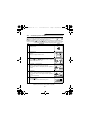
3.1 Pre-Operation Information................................................................................... 46
3.1.1 Types of operation modes ............................................................................... 46
3.1.2 Power on ......................................................................................................... 48
3.2 About the Operation Panel .................................................................................. 49
3.2.1 Names and functions of the operation panel (FR-PA02-02)............................ 49
I
2005年2月22日 火曜日 午後5時7分
3.2.2 Monitor display is changed by pressing the [MODE] key ................................ 50
3.2.3 Monitoring........................................................................................................ 50
3.2.4 Frequency setting ............................................................................................ 51
3.2.5 Parameter setting method ............................................................................... 51
3.2.6 Operation mode............................................................................................... 53
3.2.7 Help mode ....................................................................................................... 53
3.3 Operation .............................................................................................................. 56
3.3.1 Pre-operation checks....................................................................................... 56
3.3.2 External operation mode (Operation using the external frequency setting
potentiometer and external start signal) .......................................................... 57
3.3.3 PU operation mode (Operation using the operation panel) ............................. 58
3.3.4 Combined operation mode 1 (Operation using both external start signal and
operation panel)............................................................................................... 59
3.3.5 Combined operation mode 2 ........................................................................... 60
CHAPTER 4
PARAMETERS
61
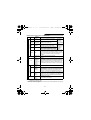
4.1 Parameter List ...................................................................................................... 62
4.1.1 Parameter list .................................................................................................. 62
4.1.2 List of parameters classified by purpose of use .............................................. 68
4.1.3 Parameters recommended to be set by the user ............................................ 70
4.2 Parameter Function Details................................................................................. 71
4.2.1
4.2.2
4.2.3
4.2.4
Torque boost (Pr. 0, Pr. 46)............................................................................. 71
Output frequency range (Pr. 1, Pr. 2, Pr. 18)................................................... 72
Base frequency, base frequency voltage (Pr. 3, Pr. 19, Pr. 47) ...................... 73
Multi-speed operation
(Pr. 4 to Pr. 6, Pr. 24 to Pr. 27, Pr. 232 to Pr. 239).......................................... 74
4.2.5 Acceleration/deceleration time (Pr. 7, Pr. 8, Pr. 20, Pr. 21, Pr. 44, Pr. 45) ..... 75
4.2.6 Electronic thermal relay function (Pr. 9, Pr. 48)............................................... 77
4.2.7 DC injection brake (Pr. 10 to Pr. 12)................................................................ 78
4.2.8 Starting frequency (Pr. 13) .............................................................................. 79
4.2.9 Load pattern selection (Pr. 14) ........................................................................ 80
4.2.10 Jog operation (Pr. 15, Pr. 16) .......................................................................... 81
4.2.11 Stall prevention and current restriction (Pr. 22, Pr. 23, Pr. 66, Pr. 156) .......... 82
4.2.12 Acceleration/deceleration pattern (Pr. 29) ....................................................... 85
4.2.13 Regenerative brake duty (Pr. 30, Pr. 70)......................................................... 86
4.2.14 Frequency jump (Pr. 31 to Pr. 36) ................................................................... 87
4.2.15 Speed display (Pr. 37) ..................................................................................... 88
4.2.16 Frequency at 5V (10V) input (Pr. 38)............................................................... 89
4.2.17 Frequency at 20mA input (Pr. 39) ................................................................... 89
4.2.18 Up-to-frequency sensitivity (Pr. 41) ................................................................. 90
4.2.19 Output frequency detection (Pr. 42, Pr. 43)..................................................... 91
4.2.20 Monitor display (Pr. 52, Pr. 158)..................................................................... 92
II
Contents
M4500E.book II ページ
M4500E.book III ページ
2005年2月22日 火曜日 午後5時7分
4.2.21 Monitoring reference (Pr. 55, Pr. 56) ............................................................... 94
4.2.22 Automatic restart after instantaneous power failure
(Pr. 57, Pr. 58) ................................................................................................. 95
4.2.23 Remote setting function selection (Pr. 59)....................................................... 97
4.2.24 Shortest acceleration/deceleration mode (Pr. 60 to Pr. 63)........................... 100
4.2.25 Retry function (Pr. 65, Pr. 67 to Pr. 69) ......................................................... 102
4.2.26 Applied motor (Pr. 71) ................................................................................... 104
4.2.27 PWM carrier frequency (Pr. 72, Pr. 240) ....................................................... 105
4.2.28 Voltage input (Pr. 73, Pr. 254) ....................................................................... 106
4.2.29 Input filter time constant (Pr. 74) ................................................................... 107
4.2.30 Reset selection/disconnected PU detection/PU stop selection (Pr. 75) ........ 108
4.2.31 Parameter write disable selection (Pr. 77)..................................................... 110
4.2.32 Reverse rotation prevention selection (Pr. 78) .............................................. 111
4.2.33 Operation mode selection (Pr. 79)................................................................. 111
4.2.34 General-purpose magnetic flux vector control selection (Pr. 80)................... 115
4.2.35 Offline auto tuning function (Pr. 82 to Pr. 84, Pr. 90, Pr. 96) ......................... 116
4.2.36 Computer link operation (Pr. 117 to Pr. 124, Pr. 342) ................................... 122
4.2.37 PID control (Pr. 128 to Pr. 134) ..................................................................... 135
4.2.38 Output current detection function (Pr. 150, Pr. 151)...................................... 143
4.2.39 Zero current detection (Pr. 152, Pr. 153)....................................................... 144
4.2.40 User group selection (Pr. 160, Pr. 173 to Pr. 176) ........................................ 145
4.2.41 Actual operation hour meter clear (Pr. 171) .................................................. 147
4.2.42 Input terminal function selection (Pr. 180 to Pr. 183) .................................... 147
4.2.43 Output terminal function selection (Pr. 190 to Pr. 192).................................. 149
4.2.44 Cooling fan operation selection (Pr. 244) ...................................................... 150
4.2.45 Slip compensation (Pr. 245 to Pr. 247).......................................................... 151
4.2.46 Stop selection (Pr. 250) ................................................................................. 152
4.2.47 Output phase failure protection selection (Pr. 251) ....................................... 153
4.2.48 Meter (frequency meter) calibration (Pr. 901)................................................ 154
4.2.49 Biases and gains of the frequency setting voltage (current)
(Pr. 902 to Pr. 905) ........................................................................................ 156
CHAPTER 5
PROTECTIVE FUNCTIONS
163
5.1 Errors (Alarms) ................................................................................................... 164
5.1.1 Error (alarm) definitions ................................................................................. 164
5.1.2 To know the operating status at the occurrence of alarm.............................. 173
5.1.3 Correspondence between digital and actual characters................................ 173
5.1.4 Resetting the inverter .................................................................................... 173
5.2 Troubleshooting ................................................................................................. 174
5.2.1
5.2.2
5.2.3
5.2.4
Motor remains stopped.................................................................................. 174
Motor rotates in opposite direction ................................................................ 174
Speed greatly differs from the setting............................................................ 175
Acceleration/deceleration is not smooth........................................................ 175
III
2005年2月22日 火曜日 午後5時7分
5.2.5 Motor current is large..................................................................................... 175
5.2.6 Speed does not increase............................................................................... 175
5.2.7 Speed varies during operation....................................................................... 175
5.2.8 Operation mode is not changed properly ...................................................... 176
5.2.9 Operation panel display is not operating ....................................................... 176
5.2.10 POWER lamp is not lit ................................................................................... 176
5.2.11 Parameter write cannot be performed ........................................................... 176
CHAPTER 6
MAINTENANCE/INSPECTION
177
6.1 Precautions for Maintenance and Inspection.................................................. 178
6.1.1
6.1.2
6.1.3
6.1.4
6.1.5
6.1.6
6.1.7
6.1.8
Precautions for maintenance and inspection................................................. 178
Check items................................................................................................... 178
Periodic inspection ........................................................................................ 178
Insulation resistance test using megger ........................................................ 179
Pressure test ................................................................................................. 179
Daily and periodic inspection......................................................................... 180
Replacement of parts .................................................................................... 183
Measurement of main circuit voltages, currents and powers ........................ 186
CHAPTER 7
SPECIFICATIONS
189
7.1 Standard Specifications .................................................................................... 190
7.1.1 Model specifications ...................................................................................... 190
7.1.2 Common specifications ................................................................................. 191
7.1.3 Outline drawings............................................................................................ 193
APPENDIX
195
APPENDIX 1 Instruction Code List .......................................................................... 196
APPENDIX 2 When using the communication option. .......................................... 200
IV
Contents
M4500E.book IV ページ
M4500E.book V ページ
MEMO
2005年2月22日 火曜日 午後5時7分
M4500E.book 1 ページ
2005年2月22日 火曜日 午後5時7分
CHAPTER 1
OUTLINE
This chapter gives information on the basic "outline" of this
product.
Always read the instructions before using the equipment.
Chapter 1
1.1 Pre-Operation Information ....................... 2
1.2 Basic Configuration.................................. 4
1.3 Structure .................................................. 5
Chapter 2
Chapter 3
<Abbreviations>
• PU
Operation panel (FR-PA02-02) and
parameter unit (FR-PU04-MGI)
• Inverter
MGI inverter M4500E series
• Pr.
Parameter number
Chapter 4
Chapter 5
Chapter 6
Chapter 7
1
M4500E.book 2 ページ
2005年2月22日 火曜日 午後5時7分
OUTLINE
1.1
1.1.1
Pre-Operation Information
Precautions for operation
This manual is written for the M4500E series transistorized inverters.
Incorrect handling may cause the inverter to operate incorrectly, causing its life to be
reduced considerably, or at the worst, the inverter to be damaged. Handle the inverter
properly in accordance with the information in each section as well as the precautions
and instructions of this manual to use it correctly.
For handling information on the parameter unit (FR-PU04-MGI), stand-alone options,
etc., refer to the corresponding manuals.
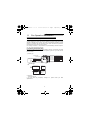
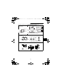
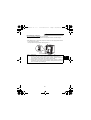
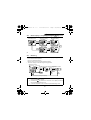
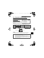
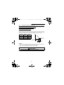
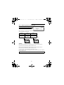
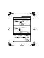
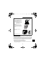
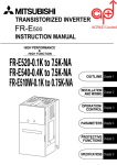
(1) Unpacking and product check
Unpack the inverter and check the capacity plate on the front cover and the rating plate
on the inverter side face to ensure that the product agrees with your order and the
inverter is intact.
1) Inverter type
Capacity plate
Rating plate
Inverter type
Input rating
Capacity plate
Capacity plate
Voltage
class
Output rating
M4500E-001
Serial number
Serial
Indicates
capacity "HP" number
MGI Technologies INVERTER
M4500E-001
:
:
:
SERIAL:
MADE IN JAPAN
Rating plate
Inverter type
M 4500E - 001
Voltage Class
Three-phase
575V class
Indicates
capacity in
"HP".
2) Accessory
Instruction manual
If you have found any discrepancy, damage, etc., please contact your sales
representative.
2
M4500E.book 3 ページ
2005年2月22日 火曜日 午後5時7分
OUTLINE
(2) Preparation of instruments and parts required for operation
Instruments and parts to be prepared depend on how the inverter is operated. Prepare
equipment and parts as necessary. (Refer to page 46.)
(3) Installation
To operate the inverter with high performance for a long time, install the inverter in a
proper place, in the correct direction, with proper clearances. (Refer to page 14.)
(4) Wiring
Connect the power supply, motor and operation signals (control signals) to the terminal
block. Note that incorrect connection may damage the inverter and peripheral devices.
(Refer to page 16.)
1
3
M4500E.book 4 ページ
2005年2月22日 火曜日 午後5時7分
OUTLINE
1.2
Basic Configuration
1.2.1
Basic configuration
The following devices are required to operate the inverter. Proper peripheral devices
must be selected and correct connections made to ensure proper operation. Incorrect
system configuration and connections can cause the inverter to operate improperly, its
life to be reduced considerably, and in the worst case, the inverter to be damaged.
Please handle the inverter properly in accordance with the information in each section
as well as the precautions and instructions of this manual. (For connections of the
peripheral devices, refer to the corresponding manuals.)
Name
Description
Use the power supply within the permissible power
supply specifications of the inverter. (Refer to page
190.)
Power supply
(MCCB)
or
(ELB)
Ground
leakage circuit The breaker should be selected with care since a
breaker or
large inrush current flows in the inverter at power
moulded case on. (Refer to page 41.)
circuit breaker
Install for your safety. (Refer to page 42.) Do not
use this magnetic contactor to start or stop the
inverter. It might reduce the inverter life. (Refer to
page 41.)
The reactors must be used when the power factor is
to be improved or the inverter is installed near a large
power supply system (500KVA or more and wiring
distance within 10m (32.81 feet)). Make selection
carefully.
Magnetic
contactor
(MC)
AC
reactor
Reactors
• The life of the inverter is influenced by ambient
temperature. The ambient temperature should be
as low as possible within the permissible range.
This must be noted especially when the inverter is
installed in an enclosure. (Refer to page 14.)
• Wrong wiring might lead to damage of the
inverter. The control signal lines should be kept
away from the main circuit to protect them from
noise. (Refer to page 16.)
DC reactor
Inverter
Ground
Ground
Devices
connected to
the output
Do not connect a power capacitor, surge suppressor
or capacitor type filter on the output side.
When installing a moulded case circuit breaker on
the output side of the inverter, contact each
manufacturer for selection of the moulded case
circuit breaker.
Ground
To prevent an electric shock, always ground the
motor and inverter.
For reduction of induction noise from the power
line of the inverter, it is recommended to wire the
ground cable by returning it to the ground terminal
of the inverter. (Refer to page 39.)
4
M4500E.book 5 ページ
2005年2月22日 火曜日 午後5時7分
OUTLINE
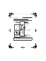
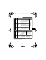
1.3
1.3.1
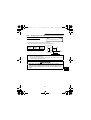
Structure
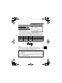
Appearance and structure
(2) Without front cover and
accessory cover
(1) Front view
Inboard option
mounting position
POWER lamp
(yellow)
Accessory cover
PU conector*
POWER lamp (yellow)
ALARM lamp (red)
Connector for connection
of inboard option
ALARM lamp (red)
Capacity plate
Rating plate
Front cover
Control circuit
terminal block
Control logic changing
jumper connector
Wiring port cover
for option
Main circuit
terminal block
Wiring cover
Lamp indication
Power lamp .......Lit when power is spplied to the main circuit (R (L1),S (L2),T (L3)).
Alarm lamp........Lit when the inverter is in the alarm status (major faults).
*Use the PU connector for the FR-PA02-02 or FR-PU04-MGI option and RS-485
communication.
5
1
M4500E.book 6 ページ
2005年2月22日 火曜日 午後5時7分
OUTLINE
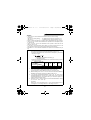
1.3.2
Removal and reinstallation of the front cover
Removal
The front cover is fixed with hooks in positions A, B and C.
Push A and B in the directions of arrows at the same time and remove the cover
using C as supporting points.
1)
A
C
B
2)
3)
C
Reinstallation
When reinstalling the front cover after wiring, fix the hooks securely.
With the front cover removed, do not switch power on.
Note: 1. Make sure that the front cover has been reinstalled securely.
2. The same serial number is printed on the capacity plate of the front cover
and the rating plate of the inverter. Before reinstalling the front cover, check
the serial numbers to ensure that the cover removed is reinstalled to the
inverter from where it was removed.
6
M4500E.book 7 ページ
2005年2月22日 火曜日 午後5時7分
OUTLINE
1.3.3
Removal and reinstallation of the wiring cover
Removal
Remove the wiring cover by pulling it in the direction of arrow A.
1
A
Wiring hole
Reinstallation
Pass the cables through the wiring hole and reinstall the cover in the original
position.
7
M4500E.book 8 ページ
2005年2月22日 火曜日 午後5時7分
OUTLINE
1.3.4
Removal and reinstallation of the accessory cover
Removal
Hold down the portion A indicated by the arrow and lift the right hand side using
the portion B indicated by the arrow as a support, and pull out the accessory cover
to the right.
B
2)
1)
3)
A
Reinstallation
Insert the mounting hook (left hand side) of the accessory cover into the mounting
position of the inverter and push in the right hand side mounting hook to install the
accessory cover.
Mounting position
Accessory
cover
1)
A
Hook
2)
3)
8
M4500E.book 9 ページ
2005年2月22日 火曜日 午後5時7分
OUTLINE
1.3.5
Reinstallation and removal of the operation panel
To ensure safety, reinstall and remove the option operation panel (FR-PA02-02) after
switching power off.
The charging area and control printed board are exposed on the rear surface of the
operation panel. When removing the operation panel, always fit the rear cover option FRE5P. Never touch the control printed board because touching it can cause the inverter to fail.
Reinstallation
Insert the mounting hook (left hand side) of the operation panel into the mounting
position of the inverter and push in the right hand side mounting catch to install the
operation panel.
Mounting position
1
FR-PA02-02
A
Hook
1)
2)
3)
Removal of the operation panel
Hold down the portion A indicated by the arrow and lift the right hand side using
the portion B indicated by the arrow as a support, and pull out the operation panel
to the right.
1)
2)
B
3)
A
(If the above procedure is not used for removal, the internal connector may be
damaged by the force applied.)
9
M4500E.book 10 ページ
2005年2月22日 火曜日 午後5時7分
OUTLINE
Using the connection cable for operation
1) Fit the rear cover option FR-E5P to the back surface of the operation panel.
2) Securely plug one end of the connection cable into the PU connector of the
inverter and the other end into the adaptor of the FR-E5P option to connect it to
the operation panel. (For the connection cable of the FR-E5P, refer to page 28.)
PU connector
(RS-485 cable specifications)
Mounting the operation panel on an enclosure
When you open the operation panel front cover, the screw mounting guides for
fixing the operation panel to an enclosure appear on the top left and bottom right.
Fit the rear cover of the FR-E5P option, drill holes in the operation panel mounting
guides, and securely mount the operation panel on the enclosure with screws.
1.3.6
Removal of the operation panel (FR-PA02-02) front cover
1)Open the operation panel front cover to 90 degrees.
2)Pull out the operation panel front cover to the left to remove it.
90 degrees
10
M4500E.book 11 ページ
2005年2月22日 火曜日 午後5時7分
OUTLINE
1.3.7
Exploded view
Operation panel (FR-PA02-02)
Front cover
Accessory
cover
1
Wiring port cover
for option
Wiring cover
CAUTION
Do not remove any parts other than the operation panel, front cover, and wiring cover
from the inverter. Doing so will damage the inverter.
11
M4500E.book 12 ページ
2005年2月22日 火曜日 午後5時7分
MEMO
12
M4500E.book 13 ページ
2005年2月22日 火曜日 午後5時7分
CHAPTER 2
INSTALLATION AND
WIRING
This chapter gives information on the basic "installation and
wiring" for use of this product.
Always read the instructions in this chapter before using the
equipment.
2.1 Installation................................................ 14
2.2 Wiring....................................................... 16
2.3 Other Wiring............................................. 34
Chapter 1
Chapter 2
Chapter 3
Chapter 4
Chapter 5
Chapter 6
Chapter 7
13
M4500E.book 14 ページ
2005年2月22日 火曜日 午後5時7分
INSTALLATION AND WIRING
2.1
2.1.1
Installation
Instructions for installation
1) Handle the unit carefully.
The inverter uses plastic parts. Handle it gently to protect it from damage.
Also, hold the unit with even strength and do not apply too much strength to the front
cover alone.
2) Install the inverter in a place where it is not affected by vibration easily (5.9m/s2
maximum).
Note the vibration of a cart, press, etc.
3) Note on the ambient temperature.
The inverter life is under great influence of the ambient temperature. In the place of
installation, the ambient temperature must be within the permissible range -10°C to
+40°C (14°F to 104°F). Check that the ambient temperature is within that range in the
positions shown in figure 3).
4) Install the inverter on a non-combustible surface.
The inverter will be very hot (maximum about 150°C (302°F)). Install it on a noncombustible surface (e.g. metal). Also leave sufficient clearances around the inverter.
5) Avoid high temperature and high humidity.
Avoid direct sunlight and places of high temperature and high humidity.
6) Avoid places where the inverter is exposed to oil mist, flammable gases, fluff, dust,
dirt etc.
Install the inverter in a clean place or inside a "totally enclosed" panel which does not
accept any suspended matter.
7) Note the cooling method when the inverter is installed in an enclosure.
When two or more inverters are installed or a ventilation fan is mounted in an
enclosure, the inverters and ventilation fan must be installed in proper positions with
extreme care taken to keep the ambient temperatures of the inverters with the
permissible values. If they are installed in improper positions, the ambient
temperatures of the inverters will rise and ventilation effect will be reduced.
14
M4500E.book 15 ページ
2005年2月22日 火曜日 午後5時7分
INSTALLATION AND WIRING
8) Install the inverter securely in the vertical direction with screws or bolts.
4) Clearances around the inverter
3) Note on ambient
temperatures
5cm
(1.97 inch)
5cm
(1.97 inch)
10cm (3.94inch) Leave sufficient
or more
clearances above Cooling air
Measurement
position
1cm (0.39inch)
or more*
Inverter
5cm
and under the
inverter to ensure
adequate ventilation.
1cm (0.39inch)
Inverter or more*
(1.97 inch)
Measurement
position
10cm (3.94inch)
or more
Cooling fan
built in the
inverter
*5cm (1.97inch) or more for 007.5 and 010
These clearances are also necessary for changing the cooling fan.
(The 002 or more is provided with a cooling fan)
7) For installation in an enclosure
Ventilation
fan
Inverter
Inverter
Inverter
Inverter
Inverter
Inverter
(Correct example) (Incorrect example)
Position of Ventilation Fan
Built-in cooling fan
(Correct example)
(Incorrect example)
When more than one inverter is contained
8) Vertical mounting
15
2
M4500E.book 16 ページ
2005年2月22日 火曜日 午後5時7分
INSTALLATION AND WIRING
2.2 Wiring
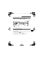
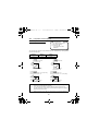
2.2.1
Terminal connection diagram
3-phase 575V power input
MCCB
MC
3-phase AC
power supply
24VDC power output and
external transistor common
R(L1)
S(L2)
T(L3)
U
V
W
PC
Note 4
P1
Motor
IM
Ground
(+)P
PR
Forward rotation start STF
(-)N
Reverse rotation start STR
Jumper
Remove this jumper when
using the optional power-factor
improving DC reactor.
Brake resistor connection
High RH
A
Multi-speed selection Middle RM
B
Low RL
C
Output stop MRS
Alarm
output
Reset RES
Contact input common SD
Note 3
RUN
FU
Control input signals
(No voltage input allowed)
SE
Note 2
Frequency setting signals (Analog)
3
(Note 1)
2
Frequency
setting
potentiometer1
1/2W1kΩ Current input(-)
4 to 20mADC(+)
When using current input as the
frequency setting signal, set "4" in
any of Pr.180 to Pr.183 (input
terminal function selection) and
assign AU (current input selection)
to any of terminal RH, RM, RL, or
MRS, then turn the AU signal on.
Note: 1.
2.
3.
4.
Running
Frequency detection
Open collector output common
Sink/source common
Open
collector outputs
10(+5V)
2 0 to 5VDC Selected
0 to 10VDC
5(Common)
Note 3
4(4 to 20mADC)
SD
Note 2
AM
5
PU connector
(RS-485)
(+) Analog signal
output
(0 to 10VDC)
Main circuit terminal
Control circuit input terminal
Control circuit output terminal
(- )
Ground
If the potentiometer is to be operated often, use a 2W1kΩ potentiometer.
Terminals SD and SE are isolated.
Terminals SD and 5 are common terminals. Do not ground them to the ground.
When terminals PC-SD are used as a 24VDC power supply, be careful not
to short these terminals. If they are shorted, the inverter will be damaged.
16
M4500E.book 17 ページ
2005年2月22日 火曜日 午後5時7分
INSTALLATION AND WIRING
(1) Description of the main circuit terminals
Symbol
Terminal Name
Description
R, S, T
(L1, L2, L3)
AC power input
U, V, W
Inverter output
Connect a three-phase squirrel-cage motor.
P (+), PR
Brake resistor
connection
Connect the optional brake resistor across terminals PPR (+ - PR).
P (+), N (-)
Brake unit
connection
Connect the optional brake unit.
P (+), P1
Power factor
improving
DC reactor
connection
Disconnect the jumper from terminals P-P1 (+ - P1) and
connect the optional power factor improving DC reactor.
Ground
For grounding the inverter chassis. Must be grounded.
Connect to the commercial power supply.
2
17
M4500E.book 18 ページ
2005年2月22日 火曜日 午後5時7分
INSTALLATION AND WIRING
(2) Description of the control circuit terminals
Type
Symbol
STF
Contact input
Input signals
STR
Turn on the STF signal to start forward
rotation and turn it off to stop.
Reverse
rotation start
Turn on the STR signal to start reverse
rotation and turn it off to stop.
RH, RM, Multi-speed
selection
RL
MRS
Output stop
RES
Reset
SD
PC
Frequency setting
10
Analog
Terminal
Name
Forward
rotation start
5
Contact input
common
(sink*)
Power output
and external
transistor
common
Contact input
common
(source*)
Frequency
setting power
supply
2
Frequency
setting
(voltage)
4
Frequency
setting
(current)
Frequency
setting
common
Description
When the STF
and STR signals
are turned on
simultaneously,
the stop command
is given.
Combine the RH, RM and RL signals as
Input terminal
appropriate to select multiple speeds.
function selection
Turn on the MRS signal (20ms or longer) (Pr. 180 to Pr.
183) changes
to stop the inverter output.
Used to shut off the inverter output to bring the terminal
motor to a stop by the electromagnetic brake. functions.
Used to reset the protective circuit activated. Turn on the
RES signal for more than 0.1s then turn it off.
Factory setting is for reset always. By setting Pr.75, reset
can be set to enabled only at an inverter alarm occurrence.
(Refer to page 108.) Recover about 1s after reset is
cancelled.
Common to the contact input terminals.
Common output terminal for 24VDC 0.1A power output (PC
terminal).
When transistor output (open collector output), such as a
programmable controller (PLC), is connected, connect the
external power supply common for transistor output to this
terminal to prevent a fault caused by undesirable current.
This terminal can be used as a 24VDC, 0.1A power output.
5VDC, permissible load current 10mA
By entering 0 to 5VDC (0 to 10VDC), the maximum
output frequency is reached at 5V (or 10V) and I/O
are proportional. Use Pr. 73 to switch between input 0
to 5VDC (factory setting) and 0 to 10VDC. Input
resistance 10kΩ. Maximum permissible voltage 20V.
By entering 4 to 20mADC, the maximum output frequency is
reached at 20mA and I/O are proportional. This input signal
is valid only when the AU signal (Note) is on (voltage input is
invalid). Input resistance approximately 250Ω. Maximum
permissible current 30mA.
Common to the frequency setting signals (terminal 2, 1 or 4).
Do not connect to the ground.
Note: Assign the AU signal to any of the terminals using the input terminal function
selection (Pr. 180 to Pr. 183).
* Used as a contact input signal common terminal by switching between sink logic and
source logic. (Refer to page 25.)
18
M4500E.book 19 ページ
2005年2月22日 火曜日 午後5時7分
INSTALLATION AND WIRING
Symbol
A, B, C
RUN
Open collector
Output signals
Contact
Type
FU
RS-485
Communication
Analog
SE
AM
Terminal
Name
Description
Alarm output
Change-over contact output indicating that
the output has been stopped by the inverter
protective function activated. 230VAC 0.3A,
30VDC 0.3A. Alarm: discontinuity across BC (continuity across A-C), normal:
continuity across B-C (discontinuity across
A-C).
Inverter
running
Switched low when the inverter output
frequency is equal to or higher than the
starting frequency (factory set to 0.5Hz,
variable). Switched high during stop or DC
injection brake operation (*1).
Permissible load 24VDC 0.1A. (a voltage
drop is 3.4V maximum when the signal is
on)
Frequency
detection
Switched low when the output frequency
has reached or exceeded the detection
frequency set as appropriate. Switched
high when the output frequency is below
the detection frequency (*1).
Permissible load 24VDC 0.1A
Output
terminal
function
selection
(Pr. 190 to
Pr. 192)
changes
terminal
functions.
Open collector
Common to the RUN and FU terminals
output common
Analog signal
output
One selected from output
frequency, motor current
and output voltage is output
(*2). The output signal is
proportional to the
magnitude of each
monitoring item.
PU connector
With the operation panel connector, communication can
be made using the RS-485 protocol.
• Conforming Standard : EIA Standard RS-485
• Transmission format
: Multi-drop link system
• Communication speed : Maximum 19200bps
• Overall length
: 500m (1640.40 feet)
Factory setting of output
item:
Frequency output signal 0
to 10 VDC
Permissible load current
1mA
*1: Low indicates that the open collector output transistor is on (conducts). High
indicates that the transistor is off (does not conduct).
*2: Not output during inverter resetting.
19
2
M4500E.book 20 ページ
2005年2月22日 火曜日 午後5時7分
INSTALLATION AND WIRING
2.2.2
Wiring of the Main Circuit
(1) Wiring instructions
1) It is recommended to use insulation-sleeved crimping terminals for power supply and
motor cables.
2) Application of power to the output terminals (U, V, W) of the inverter will damage the
inverter. Never perform such wiring.
3) After wiring, wire off-cuts must not be left in the inverter.
Wire off-cuts can cause an alarm, failure or malfunction. Always keep the inverter clean.
When drilling mounting holes in a control box etc., be careful so that chips and others
do not enter the inverter.
4) Use thick cables to make the voltage drop 2% or less.
If the wiring distance is long between the inverter and motor, a main circuit cable voltage
drop will cause the motor torque to decrease, especially at the output of a low frequency.
(A selection example for the wiring length of 20m (65.62 feet) is shown on page 22.)
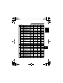
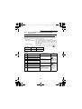
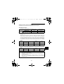
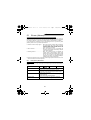
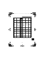
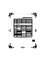
5) The overall wiring length should be 500m (1640.40feet) maximum.
Especially for long distance wiring, the fast-response current limit may be misactivated
under the influence of a charging current due to the stray capacitance of the wiring.
The fast-response current limit must be turn off by Pr.156 when the total wiring length
is more than the indicated value in the following table for M4500E-001 to 010.
Inverter Capacity
Non-low acoustic
noise mode
Low acoustic
noise mode
001
100
(328.08)
100
(328.08)
002
100
(328.08)
100
(328.08)
003
100
(328.08)
100
(328.08)
005
200
(656.16)
200
(656.16)
007.5
010
400
500
(1312.34) (1640.40)
300
400
(984.24) (1312.34)
(Unit: m (feet))
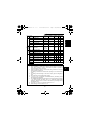
Even though the fast-response current limit is turned off , in more long distance wiring
situations the over current protection may be misactivated or the devices connected
to the output side may misoperate or become faulty under the influence of a charging
current due to the stray capacitance of the wiring.
Therefore, the maximum overall wiring length should be as indicated in the following
table. (When two or more motors are connected to the inverter, the total wiring length
should be within the indicated value.)
Inverter Capacity
Total wiring length
001
100 (328.08)
002
200 (656.16)
003
300 (984.24)
Overall wiring length (005 or more)
500m (1640.40 feet)
maximum
300m
(984.24 feet)
300m
(984.24 feet)
300m (984.24 feet)+300m (984.24 feet)=600m (1968.48 feet)
20
005 or more
500 (1640.40)
(Unit: m (feet))
M4500E.book 21 ページ
2005年2月22日 火曜日 午後5時7分
INSTALLATION AND WIRING
6) Connect only the recommended optional brake resistor between the terminals P-PR
(+ - PR).
These terminals must not be shorted.
Also, never short these terminals.
7) Electromagnetic wave interference
The input/output (main circuit) of the inverter includes harmonic components, which
may interfere with the communication devices (such as AM radios) used near the
inverter. In this case, install the FR-BSF01 or FR-BLF line noise filter to minimize
interference.
8) Do not install a power capacitor, surge suppressor or capacitor type filter on the
output side of the inverter.
This will cause the inverter to trip or the capacitor and surge suppressor to be
damaged. If any of the above devices are installed, immediately remove them.
9) When rewiring after operation, make sure that the POWER lamp has gone off, and
when more than 10 minutes has elapsed after power-off, check with a meter etc. that
the voltage is zero. After that, start rewiring work. For some time after power-off, there
is a dangerous voltage in the capacitor.
Notes on Grounding
Leakage currents flow in the inverter. To prevent an electric shock, the inverter and
motor must be grounded. Grounding must conform to the requirements of national
and local safety regulations and electrical codes.
(JIS, NEC section 250, IEC 536 class 1 and other applicable standards)
Use the dedicated ground terminal to ground the inverter. (Do not use the screw in
the case, chassis, etc.) For the ground connection, avoid direct contact between
aluminium and copper. Tin-plated cable lugs can be used if the plating does not
contain zinc. When tightening the screws, take care not to damage the thread in
the aluminium frame.
Use the thickest possible ground cable. Use the cable whose size is equal to or
greater than that indicated below, and minimize the cable length. The grounding
point should be as near as possible to the inverter.
(Unit: mm2)
Motor Capacity
Ground Cable Gauge
3.7kW (5HP) or less
3.5
5.5kW (7.5HP), 7.5kW (10HP)
5.5
Ground the motor on the inverter side using one wire of the 4-core cable.
21
2
M4500E.book 22 ページ
2005年2月22日 火曜日 午後5時7分
INSTALLATION AND WIRING
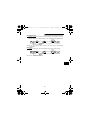
(2) Terminal block layout of the power circuit
N/-
P1 P/+ PR
R/L1 S/L2 T/L3
U
V
W
TB1
Screw size (M4)
Screw size (M4)
* A jumper is connected across P1-P/+.
(3) Cables, crimping terminals, etc.
The following table lists the cables and crimping terminals used with the inputs (R (L1), S
(L2), T (L3)) and outputs (U, V, W) of the inverter and the torques for tightening the screws:
Terminal
Applicable Inverter Type
Screw
Size
M4500E-001
M4500E-002
M4500E-003
M4500E-005
M4500E-007.5
M4500E-010
M4
M4
M4
M4
M4
M4
HIV Cables
Tight-
Crimping
ening
Terminals
R, S, T
U, V, W
(L1, L2, L3)
Torque
N⋅m
1
1
1
1
1
1
2-4
2-4
2-4
2-4
2-4
5.5-4
2-4
2-4
2-4
2-4
2-4
2-4
mm 2
R, S, T
(L1, L2, L3)
2
2
2
2
2
3.5
AWG
U, V, W
2
2
2
2
2
2
R, S, T
(L1, L2, L3)
14
14
14
14
14
12
U, V, W
14
14
14
14
14
14
Note: 1. The cables used should be 75°C (167°F) copper cables.
2. Tighten the terminal screws to the specified torques.
Undertightening can cause a short or misoperation.
Overtightening can cause the screws and unit to be damaged, resulting in a
short or misoperation.
22
M4500E.book 23 ページ
2005年2月22日 火曜日 午後5時7分
INSTALLATION AND WIRING
(4) Connection of the power supply and motor
Three-phase power input
Three-phase
power supply
S
T
R
(L1) (L2) (L3)
U
R
S
T
(L1) (L2) (L3)
V
U
Ground
terminal
W
V
Motor
W
Ground
MCCB
The power supply cables must be connected
to R, S, T (L1, L2 ,L3). If they are connected to
U, V, W, the inverter will be damaged.
(Phase sequence need not be matched.)
Note:
2.2.3
Connect the motor to U, V, W. In the above
connection, turning on the forward rotation switch (signal)
rotates the motor in the counterclockwise (arrow) direction
when viewed from the load shaft.
To ensure safety, connect the power input to the inverter via a magnetic
contactor and ground leakage circuit breaker or moulded case circuit
breaker, and use the magnetic contactor to switch power on-off.
Wiring of the control circuit
(1) Wiring instructions
1) Terminals SD, SE and 5 are common to the I/O signals. These common terminals must
not be grounded to the ground.
Terminals SD and 5 are isolated. Avoid connecting the terminal SD and 5 and the
terminal SE and 5.
2) Use shielded or twisted cables for connection to the control circuit terminals and run them
away from the main and power circuits.
3) The frequency input signals to the control circuit are micro currents. When contacts
are required, use two or more parallel micro signal contacts or a twin contact to
prevent a contact fault.
4) It is recommended to use the cables of 0.3mm2 to 0.75mm2 gauge for connection to
the control circuit terminals.
23
2
M4500E.book 24 ページ
2005年2月22日 火曜日 午後5時7分
INSTALLATION AND WIRING
(2) Terminal block layout
In the control circuit of the inverter, the terminals are arranged as shown below:
Terminal screw size: M2.5
Terminal layout of control circuit
RH
RM
RL
MRS
RES
SD
AM
PC
SE
RUN
FU
A
B
C
10
2
5
4
SD
STF
STR
SD
(3) Wiring method
1) For wiring the control circuit, use cables after stripping their sheaths.
Refer to the gauge printed on the inverter and strip the sheaths to the following
dimensions. If the sheath is stripped too much, its cable may be shorted with the
adjoining cable. If the sheath is stripped too little, the cable may come off.
7mm ± 1mm (0.28inch ± 0.04inch)
2) When using bar terminals and solid wires for wiring, their diameters should be 0.9mm
maximum. If they are larger, the threads may be damaged during tightening.
3) Loosen the terminal screw and insert the cable into the terminal.
4) Tighten the screw to the specified torque.
Undertightening can cause cable disconnection or misoperation. Overtightening can
cause damage to the screw or unit, leading to short circuit or misoperation.
Tightening torque: 0.25N⋅m to 0.49N⋅m
*Use a size 0 screwdriver to tighten.
Note: When routing the stripped cables, twist them so that they do not become loose.
In addition, do not solder it.
24
M4500E.book 25 ページ
2005年2月22日 火曜日 午後5時7分
INSTALLATION AND WIRING
(4) Control logic changing
The input signal logic is factory-set to the sink logic.
To change the control logic, the position of the jumper connector must be changed.
1) Use tweezers etc. to remove the jumper connector in the sink logic position and fit it
in the source logic position.
Do this position changing before switching power on.
Jumper
connector
Note: 1. Make sure that the front cover has been installed securely.
2. The front cover has a capacity plate and the inverter a rating plate on it.
Since these plates have the same serial numbers, always reinstall the
removed cover to the inverter from where it was removed.
3. Always install the sink-source logic changing jumper connector in either of
the positions. If two connectors are installed in these positions at the same
time, the inverter may be damaged.
25
2
M4500E.book 26 ページ
2005年2月22日 火曜日 午後5時7分
INSTALLATION AND WIRING
2) Sink logic type
• In this logic, a signal switches on when a current flows out of the corresponding signal
input terminal.
Terminal SD is common to the contact input signals. Terminal SE is common to the
open collector output signals.
Inverter
Current
AX40
R
STF
1
RUN
R
R
R
STR
9
SE
SD
24VDC
• Use terminal PC as a common terminal to prevent a malfunction caused by
undesirable current.
(Do not connect terminal SD of the inverter with terminal 0V of the external power
supply. When using terminals PC-SD as a 24VDC power supply, do not install the
power supply in parallel outside the inverter. Doing so may cause misoperation due to
undesirable current.)
Inverter
AY40 type
transistor output
module
1
STF
2
STR
24VDC
(SD)
9
PC
10
24VDC SD
Current flow
26
M4500E.book 27 ページ
2005年2月22日 火曜日 午後5時7分
INSTALLATION AND WIRING
3) Source logic type
• In this logic, a signal switches on when a current flows into the corresponding signal
input terminal.
Terminal PC is common to the contact input signals. Terminal SE is common to the
open collector output signals.
Inverter
PC
RUN
Current
AX80
1
STF
R
R
SE
R
STR
24VDC
9
R
• When using an external power supply for transistor output, use terminal SD as a
common to prevent misoperation caused by undesirable current.
AY-80 type
transistor output
module.
9
Inverter
STF
2
STR
24VDC
1
10
2
PC
24VDC
(SD)
SD
Current flow
(5) How to use the STOP signal
The following connection example shows how to self-hold the start signals (forward
rotation, reverse rotation).
Use Pr. 180 to Pr. 183 (input terminal function selection) to assign the STOP signal.
Stop
RL
(STOP)
MRS
RES
SD
Forward
rotation
Reverse
rotation
STF
STR
(Wiring example for sink logic)
27
M4500E.book 28 ページ
2005年2月22日 火曜日 午後5時7分
INSTALLATION AND WIRING
2.2.4
Connection to the PU connector
(1) When connecting the operation panel or parameter unit using a cable
Use the option FR-CB2 or the following connector and commercially available
cable:
<Connection cable>
• Connector: RJ45 connector
Example: 5-554720-3, Tyco Electronics Corporation
• Cable:
:Cable conforming to EIA568 (e.g. 10BASE-T cable)
<When using the operation panel>
Note: The rear cover and junction adaptor are required since the circuit board is
exposed in the back of the operation panel. Use the FR-E5P option (cover and
adaptor available as a set).
<Maximum wiring length>
• Operation panel (FR-PA02-02): 20m (65.62 feet)
• Parameter unit (FR-PU04-MGI): 20m (65.62 feet)
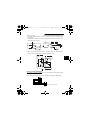
(2) For RS-485 communication
The PU connector can be used for communication
operation from a personal computer etc.
When the PU connector is connected with a personal,
FA or other computer by a communication cable, a
user program can run and monitor the inverter or read
and write to the parameters.
1) SG
2) P5S
3) RDA
4) SDB
<PU connector pin-outs>
Viewed from the inverter (receptacle side) front
5) SDA
6) RDB
7) SG
8) P5S
8) to 1)
Note: 1. Do not connect the PU connector to a computer's LAN board, FAX modem
socket or telephone modular connector. Otherwise, the product may be
damaged due to electrical specification differences.
2. Pins 2) and 8) (P5S) provide power to the operation panel or parameter
unit.
Do not use these pins for RS-485 communication.
3. Refer to page 122 for the communication parameters.
28
M4500E.book 29 ページ
2005年2月22日 火曜日 午後5時7分
INSTALLATION AND WIRING
<System configuration example>
(1) Connection of a computer to the inverter (1:1 connection)
Computer
RS-485
interface/
terminal
Station 0
Inverter
RS-485
connector
Station 0
Inverter
Computer
RS-232C
connector
RS-232C
cable
RS-232C
converter
Max. 15m
(49.21 feet)
RS-485
RJ-45 connector 2)
10BASE-T cable 1)
RS-485
connector
RJ-45 connector 2)
10BASE-T cable 1)
Computer-inverter connection cable
For a connection cable between the computer having RS-232C and the inverter (RS232C⇔RS-485 converter), refer to the table below.
Example of product available on the market (as of April, 2004)
Model
FA-T-RS40*
Maker
Mitsubishi Electric Engineering Co., Ltd.
* The converter cable cannot connect two or more inverters (the computer and
inverter are connected on a 1:1 basis). Since the product is packed with the RS232C cable and RS-485 cable (10BASE-T + RJ-45 connector), the cable and
connector need not be prepared separately. Contact a maker for details of the
product.
REMARKS
Refer to the following when fabricating the cable on the user side.
Example of product available on the market (as of April, 2004)
Product
1) 10BASE-T cable
2) RJ-45 connector
Model
SGLPEV-T 0.5mm × 4P
* Do not use No. 2 and No. 8
pin (P5S).
5-554720-3
29
Maker
Mitsubishi Cable Industries, Ltd.
Tyco Electronics Corporation
2
M4500E.book 30 ページ
2005年2月22日 火曜日 午後5時7分
INSTALLATION AND WIRING
(2) Connection of a computer to multiple inverters (1:n connection)
Computer
RS-485
interface/
terminal
Station n
(Max. 32 inverters)
Station 0
Station 1
Inverter
Inverter
Inverter
RS-485
connector
RS-485
connector
RS-485
connector
Distributor 3)
Termination resistor
10BASE-T cable 1)
Computer
RS-232C
connector
RJ-45 connector 2)
Station 1
Station 2
Inverter
Inverter
Station n
Inverter
RS-485
connector
RS-485
connector
RS-485
connector
Max. 15m
(49.21 feet)
RS-232C
cable
Converter
Distributor
3)
Termination resistor
10BASE-T cable 1)
RJ-45 connector 2)
REMARKS
Refer to the following when fabricating the cable on the user side.
Example of product available on the market (as of April, 2004)
Product
1) 10BASE-T cable
2) RJ-45 connector
Model
SGLPEV-T 0.5mm × 4P*
5-554720-3
Maker
Mitsubishi Cable Industries, Ltd.
Tyco Electronics Corporation
* Do not use No. 2 and No. 8 pin (P5S) of the 10 BASE-T cable.
30
M4500E.book 31 ページ
2005年2月22日 火曜日 午後5時7分
INSTALLATION AND WIRING
<Wiring methods>
1) Wiring of one RS-485 computer and one inverter
Computer Side Terminals
Signal name
Description
RDA
Receive data
RDB
Receive data
SDA
Send data
SDB
Send data
RSA
Request to send
RSB
CSA
CSB
SG
FG
Cable connection and signal direction
Inverter
PU connector
SDA
SDB
RDA
RDB
10 BASE-T Cable
Request to send
Clear to send
Clear to send
Signal ground
Frame ground
(Note 1)
0.2mm2 or more
SG
2) Wiring of one RS-485 computer and "n" inverters (several inverters)
Cable connection and signal direction
10 BASE-T Cable
RDB
RDA
SDB
SDA
(Note 1)
RDB
RDA
SDB
SDA
Termination
resistor
(Note 2)
RDB
RDA
SDB
SDA
Computer
RDA
RDB
SDA
SDB
RSA
RSB
CSA
CSB
SG
FG
SG
Station 1
SG
Station 2
SG
Station n
Inverter
Inverter
Inverter
Note: 1. Make connections in accordance with the instruction manual of the
computer used.
Fully check the terminal numbers of the computer as they differ between
models.
2. There may be the influence of reflection depending on the transmission
speed and/or transmission distance. If this reflection hinders
communication, provide a termination resistor. If the PU connector is used
to make a connection, use the distributor as a termination resistor cannot
be fitted.
Connect the termination resistor to only the inverter remotest from the
computer. (Termination resistor: 100Ω)
31
2
M4500E.book 32 ページ
2005年2月22日 火曜日 午後5時7分
INSTALLATION AND WIRING
2.2.5
Connection of stand-alone option units
The inverter accepts a variety of stand-alone option units as required.
Incorrect connection will cause inverter damage or an accident. Connect and operate
the option unit carefully in accordance with the corresponding option unit manual.
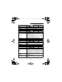
(1) Connection of the dedicated external brake resistor (option)
Connect a brake resistor across terminals P (+) and PR. Connect a dedicated brake
resistor only.
(For the locations of terminals P (+) and PR, refer to the terminal block layout (page
22).)
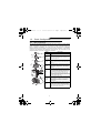
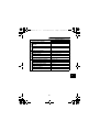
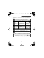
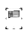
The external brake resistor should be as listed in the following table. Selected the rated
power of the brake resistor according to the brake duty.(The rated power indicated
below assumes that the brake resistor duty is 10%)
Inverter size
Brake resistance
Reference rated power at brake duty of 10%
001
1000 ohm minimum
180W minimum
002
500 ohm minimum
360W minimum
003
350 ohm minimum
500W minimum
005
200 ohm minimum
800W minimum
007.5
150 ohm minimum
1200W minimum
010
110 ohm minimum
1600W minimum
N(-) P1 P(+) PR
Brake resistor
(2) Connection of the power factor improving DC reactor
Connect the power factor
improving DC reactor between
terminals P1-P (+). In this case,
the jumper connected across
terminals P1-P (+) must be
removed. Otherwise, the reactor
will not function.
<Connection method>
N
P
( ) P1 (+) PR
DC reactor
Remove the jumper.
Note: 1. The wiring distance should be within 5m (16.40 feet).
2. The size of the cables used should be equal to or larger than that of the
power supply cables (R (L1), S (L2), T (L3)).
32
M4500E.book 33 ページ
2005年2月22日 火曜日 午後5時7分
INSTALLATION AND WIRING
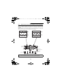
2.2.6
Design information
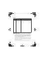
1) When performing commercial power supply-inverter switch-over operation, securely
provide electrical and mechanical interlocks for the MC1 and MC2 used for
commercial power supply-inverter switch-over.
When there is a commercial power supply-inverter switch-over circuit as shown
below, the inverter will be damaged by leakage current from the power supply due to
arcs generated at the time of switch-over or chattering caused by a sequence error.
2) If the machine must not be restarted when power is restored after a power failure,
provide a magnetic contactor in the inverter's primary circuit and also make up a
sequence which will not switch on the start signal.
If the start signal (start switch) remains on after a power failure, the inverter will
automatically restart as soon as the power is restored.
3) Since the input signals to the control circuit are on a low level, use two or more
parallel micro signal contacts or a twin contact for contact inputs to prevent a contact
fault.
4) Do not apply a large voltage to the contact input terminals (e.g. STF) of the control
circuit.
5) Always apply a voltage to the alarm output terminals (A, B, C) via a relay coil, lamp
etc.
6) Make sure that the specifications and rating match the system requirements.
1) Commercial power supply-inverter
switch-over
Power
supply
3) Low-level signal contacts
MC1
Interlock
R (L1) U
IM
S (L2) V
MC2
T (L3) W Leakage current
Inverter
Low-level signal contacts
33
Twin contact
2
M4500E.book 34 ページ
2005年2月22日 火曜日 午後5時7分
INSTALLATION AND WIRING
2.3
2.3.1
Other Wiring
Power supply harmonics
Power supply harmonics may be generated from the converter section of the inverter,
affecting the power supply equipment, power capacitor, etc. Power supply harmonics
are different in generation source, frequency band and transmission path from radio
frequency (RF) noise and leakage currents. Take the following counter measures.
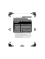
The differences between harmonics and RF noises are indicated below:
Environment
Quantitative
understanding
Generated
amount
Immunity of
affected
device
Examples of
safeguard
Harmonics
Normally 40th to 50th degrees or
less (up to 3kHz or less)
To wire paths, power impedance
Approximately proportional to
load capacity
RF Noise
High frequency (several 10kHz to
1GHz order)
Across spaces, distance, laying paths
Occurs randomly, quantitative
understanding is difficult.
According to current fluctuation rate
(larger with faster switching)
Specified in standards for each
device.
Differs according to maker's device
specifications.
Install a reactor.
Increase the distance.
Logical computation is possible
Countermeasures
The harmonic current generated from the
inverter to the power supply differs according
to various conditions such as the wiring
impedance, whether a power factor
improving reactor is used or not, and output
frequency and output current on load side.
For the output frequency and output current,
the adequate method is to obtain them under
rated load at the maximum operating
frequency.
Power factor
improving DC
reactor
MCCB
Inverter
Item
Frequency
Power factor
improving AC
reactor
Motor
IM
Do not insert power
factor improving capacitor
Note: A power factor improving capacitor and surge suppressor on the inverter's
output side may overheat or be damaged due to the harmonics of the inverter
output. Also, when an overcurrent flows in the inverter, the overcurrent
protection is activated. Hence, when the motor is driven by the inverter, do not
install a capacitor or surge suppressor on the inverter's output side. To improve
the power factor, insert a power factor improving reactor in the inverter's input
or DC circuit.
34
M4500E.book 35 ページ
2005年2月22日 火曜日 午後5時7分
INSTALLATION AND WIRING
2.3.2
Inverter-generated noise and reduction techniques
Some noises enter the inverter causing it to incorrectly operate, and others are radiated
by the inverter causing misoperation of peripheral devices. Though the inverter is
designed to be insusceptible to noise, it handles low-level signals, so it requires the
following basic measures to be taken. Also, since the inverter chops the output at high
carrier frequencies, it could generate noise. If these noises cause peripheral devices to
misoperate, measures should be taken to suppress noise. The measures differ slightly
depending on noise propagation paths.
1) Basic measures
• Do not run the power cables (I/O cables) and signal cables of the inverter in parallel
with each other and do not bundle them.
• Use twisted shield cables for the detector connecting and control signal cables and
connect the sheathes of the shield cables to terminal SD.
• Ground the inverter, motor, etc. at one point.
2) Measures against noise which enters and causes misoperation of the inverter
When devices which generate noise (devices which use magnetic contactors,
magnetic brakes, many relays, for example) are installed near the inverter, the
inverter may misoperate due to noise. The following measures must be taken:
• Provide surge suppressors for devices that generate noise to suppress noise.
• Fit data line filters (refer to page 38) to signal cables.
• Ground the shields of the detector connection and control signal cables with cable
clamp metal.
35
2
M4500E.book 36 ページ
2005年2月22日 火曜日 午後5時7分
INSTALLATION AND WIRING
3) Measures against noises which are radiated by the inverter causing misoperation of
peripheral devices.
Inverter-generated noises are largely classified into those radiated by the cables
connected to the inverter and inverter main circuit (I/O), those electromagnetically
and electrostatically inducted to the signal cables of the peripheral devices close to
the main circuit power supply, and those transmitted through the power supply
cables.
Inverter-generated
noise
Air-propagated
noise
Noise directly radiated by
inverter
··· Path 1)
Noise radiated by power
cables
··· Path 2)
Noise radiated by motor
cables
··· Path 3)
Magnetic induc··· Path 4), 5)
tion noise
Static induction
noise
··· Path 6)
Cable propagated noise
Noise propagated through
power cables
··· Path 7)
Leakage noise from ground
cable due to leakage current
··· Path 8)
5)
7)
Telephone
7)
2)
1)
Instrument
Receiver
Sensor
power supply
3) Inverter
6)
1)
4)
Motor IM
36
3) Sensor
8)
M4500E.book 37 ページ
2005年2月22日 火曜日 午後5時7分
INSTALLATION AND WIRING
Noise Path
Measures
1), 2), 3)
When devices which handle low-level signals and are susceptible to
misoperation due to noise (such as instruments, receivers and
sensors) are installed near the inverter and their signal cables are
contained in the same panel as the inverter or are run near the
inverter, the devices may be misoperated by air-propagated noise
and the following measures must be taken:
(1) Install easily affected devices as far away as possible from the
inverter.
(2) Run easily affected signal cables as far away as possible from the
inverter.
(3) Do not run the signal cables and power cables (inverter I/O
cables) in parallel with each other and do not bundle them.
(4) Insert line noise filters onto I/O and capacitor type filters into
inputs to suppress cable-radiated noises.
(5) Use shielded cables for signal cables and power cables and run
them in individual metal conduits to further reduce effects.
4), 5), 6)
When the signal cables are run in parallel with or bundled with the
power cables, magnetic and static induction noises may be
propagated to the signal cables causing misoperation of the devices
and the following measures must be taken:
(1) Install easily affected devices as far away as possible from the
inverter.
(2) Run easily affected signal cables as far away as possible from the
inverter.
(3) Do not run the signal cables and power cables (inverter I/O
cables) in parallel with each other and do not bundle them.
(4) Use shielded cables for signal cables and power cables and run
them in individual metal conduits to further reduce effects.
7)
When the power supplies of the peripheral devices are connected to
the power supply of the inverter within the same line, invertergenerated noise may flow back through the power supply cables
causing misoperation of the devices and the following measures
must be taken:
(1) Install the capacitor type filter to the power cables (input cables) of
the inverter.
(2) Install the line noise filter (FR-BLF, FR-BSF01) to the power
cables (I/O cables) of the inverter.
8)
When a closed loop circuit is formed by connecting the peripheral
device wiring to the inverter, leakage current may flow through the
ground cable of the inverter causing misoperation of the device. In
such a case, disconnection of the ground cable of the device may
cause the device to operate properly.
37
2
M4500E.book 38 ページ
2005年2月22日 火曜日 午後5時7分
INSTALLATION AND WIRING
Data line filter
Noise entry can be prevented by providing a data line filter for the detector or other
cable.
Example of counter measures against noise
FR-BLF
FR-BSF01
to inverter input side.
Install filter
Control box Reduce carrier frequency.
Inverter
power supply
FRBSF01
Inverter
Install capacitor type filter
to inverter input side.
Separate inverter and power line by more
than 30cm (11.81inches) and at least
10cm (3.94inches) from sensor circuit.
Control power
supply
Do not ground control
box directly.
Do not ground control cable.
FRBSF01
FR-BLF
to
FR-BSF01
inverter output side.
Motor
Install filter
IM
Use 4-core cable for motor power
cable and use one wire as ground
cable.
Use twisted pair shielded cable.
Sensor
Power supply
for sensor
Do not ground shield but connect it to signal
common cable.
38
M4500E.book 39 ページ
2005年2月22日 火曜日 午後5時7分
INSTALLATION AND WIRING
2.3.3
Leakage currents and countermeasures
Due to the static capacitance existing in the inverter I/O wiring and motor, leakage
currents flow through them. Since their values depend on the static capacitance, carrier
frequency, etc., take the following measures.
(1) To-ground leakage currents
Leakage currents may flow not only into the inverter's own line but also into the other
lines through the ground cable, etc. These leakage currents may operate ground
leakage circuit breakers and ground leakage relays unnecessarily.
Countermeasures
• If the carrier frequency setting is high, decrease the carrier frequency (Pr. 72) of the
inverter.
Note that motor noise increases. Selection of Soft-PWM (Pr. 240) will make it
unoffending.
• By using ground leakage circuit breakers designed for harmonic and surge
suppression in the inverter's own line and other line, operation can be performed
with the carrier frequency kept high (with low noise).
To-ground leakage current
• Note that a long wiring length will increase leakage currents. Decrease the carrier
frequency of the inverter to reduce leakage currents.
• Higher motor capacity leads to larger leakage currents.
(2) Line-to-line leakage currents
Harmonics of leakage currents flowing in static capacities between the inverter output
cables may operate the external thermal relay unnecessarily.
MCCB
Power
supply
Thermal relay
Motor
Inverter
IM
Line static capacitances
Line-to-line leakage current path
39
2
M4500E.book 40 ページ
2005年2月22日 火曜日 午後5時7分
INSTALLATION AND WIRING
Countermeasures
• Use the electronic thermal relay function of the inverter.
• Decrease the carrier frequency. Note that motor noise increases. Selection of SoftPWM will make it unoffending.
To ensure that the motor is protected not to be influenced by line-to-line leakage
currents, we recommend the protection method which uses a temperature sensor
to directly detect motor temperature.
2.3.4
Inverter-driven 575V class motor
Voltage at a motor terminal (%)
In the PWM type inverter, a surge voltage attributable to wiring constants is generated at
the motor terminals. Especially for a 575V class motor, the surge voltage may
deteriorate the insulation.
200
150
100 %
0
10
20
30
40
50
60
70
80
90
100
Motor wiring length (m)
Surge voltage at a motor terminal by motor wiring length (reference)
When the 575V class motor is driven by the inverter, consider the following measures:
Measures
(1) Inverter duty motor
Select an inverter duty motor. Many motor manufacturers sell motors with insulation
systems designed to withstand the stress imposed by PWM inverters.
(2) AC reactor
For added protection, install an AC reactor on the inverter output.
40
M4500E.book 41 ページ
2005年2月22日 火曜日 午後5時7分
INSTALLATION AND WIRING
2.3.5
Peripheral devices
(1) Selection of peripheral devices
Check the capacity of the motor to be used with the inverter you purchased.
Appropriate peripheral devices must be selected according to the capacity.
Refer to the following list and prepare appropriate peripheral devices:
Moulded case circuit breaker (MCCB)
or Ground Leakage Circuit Breaker
(NV) (Note 5)
Motor
Output
(kW)
(HP)
Power
Supply
Capacity
(kVA)
M4500E-001
0.75 (1)
2.5
5A
5A
3A
M4500E-002
1.5 (2)
4.5
10A
10A
5A
2.2 (3)
5.5
Inverter Type
M4500E-003
M4500E-005
Standard
With power factor
improving
reactor
15A
Magnetic
Contactor (MC)
10A
7A
3.7 (5)
9
20A
15A
10A
M4500E-007.5
5.5 (7.5)
12
30A
20A
15A
M4500E-010
7.5 (10)
17
30A
30A
21A
Note: 1. • Select the MCCB according to the inverter power supply capacity.
• Install one MCCB per inverter.
MCCB
INV
IM
MCCB
INV
IM
2. The power supply cable size of the motor indicated assumes that its length is
20m (65.62 feet).
3. When the inverter capacity is greater than the motor capacity, choose the
breaker and magnetic contactor in accordance with the inverter type and
choose the cables and power factor improving reactor in accordance with the
motor output.
4. When the breaker on the inverter primary side trips, check for the wiring fault
(short circuit), damage to internal parts of the inverter, etc. Identify the cause of
the trip, then remove the cause and power on the breaker.
5. For installations in the United States or Canada, the circuit breaker must be
inverse time or instantaneous trip type.
Installation and selection of moulded case circuit breaker
Install a moulded case circuit breaker (MCCB) in the power supply side for protection of
the inverter's primary wiring. Refer to the previous table and choose the MCCB
according to the inverter's power supply side power factor (which changes with the
power supply voltage, output frequency and load). Especially for a completely
electromagnetic type MCCB, the one with a larger capacity must be selected since its
operational characteristics change with harmonic currents. (Check the data of the
corresponding breaker for confirmation.) Also the ground leakage circuit breaker used
should be durable against harmonics/surges.
41
2
M4500E.book 42 ページ
2005年2月22日 火曜日 午後5時7分
INSTALLATION AND WIRING
2.3.6
Power off and magnetic contactor (MC)
(1) Inverter primary side magnetic contactor (MC)
On the inverter primary side, it is recommended to provide an MC for the following
purposes. (Refer to page 41 for selection.)
1) To release the inverter from the power supply when the inverter protective function
is activated or the drive becomes faulty (e.g. emergency stop operation)
When cycle operation or heavy-duty operation is performed with an optional brake
resistor connected, overheat and burnout of the electrical-discharge resistor can
be prevented if a regenerative brake transistor is damaged due to insufficient heat
capacity of the electrical-discharge resistor and excess regenerative brake duty.
2) To prevent any accident due to an automatic restart at restoration of power after an
inverter stop made by a power failure
3) To rest the inverter for an extended period of time
The control power supply for inverter is always running and consumes a little
power. When stopping the inverter for a long time, switching inverter power off
saves power slightly.
4) To separate the inverter from the power supply to ensure safe maintenance and
inspection work
As the inverter's primary MC is used for the above purposes, select the one of
class JEM1038-AC3 for the inverter input side current when making an emergency
stop during normal operation.
REMARKS
The MC may be switched on/off to start/stop the inverter. However, since repeated
inrush currents at power-on will shorten the life of the converter circuit (switching life is
about 100,000 times), frequent starts and stops must be avoided.
Turn on/off the inverter start controlling terminals (STF, STR) to run/stop the inverter.
Inverter Start/Stop Circuit
Example
As shown on the right, always
use the start signal (ON or OFF
across terminals STF or STRSD) to make a start or stop.
(Refer to page 18.)
MCCB
MC
R
Power
supply
U
S
V
T
W
To
motor
T (*1)
Inverter
Operation ready
REMARKS
OFF
*1 Install a step-down
transformer.
A
ON
B
MC
MC
C
RA
STF(STR)
SD
Start/Stop
MC
Operation
RA
OFF
RA
(2) Handling of secondary side magnetic contactor
Note that if it is switched off then on again during operation when the magnetic
contactor is installed between the inverter and motor, a large inrush current may flow,
affecting the motor.
42
M4500E.book 43 ページ
2005年2月22日 火曜日 午後5時7分
INSTALLATION AND WIRING
2.3.7
Instructions for UL, cUL
(Standard to comply with: UL 508C, CSA C22.2 No. 14)
(1) Installation
The below types of inverter have been approved as products for
use in enclosure and approval tests were conducted under the following conditions.
Design the enclosure so that the ambient temperature, humidity and ambience of the
inverter will satisfy the above specifications.
Branch circuit protection
For installation in United States, the Class K5 or equivalent for the branch circuit
protection must be provided, in accordance with the National Electrical Code and any
applicable local codes.
For installation in Canada, the Class K5 or equivalent for the branch circuit protection
must be provided, in accordance with the Canada Electrical Code and any applicable
provincial codes.
M4500E-
Rated voltage (V)
Rated current (A)
001
002
6
10
003
005
600V or more
15
20
007.5
010
30
40
(2) Wiring of the power supply and motor
Use the UL-listed cables (rated at 75°C (167°F)) and round crimping terminals to wire
the input (R (L1), S (L2), T (L3)) and output (U, V, W) terminals of the inverter. Crimp the
terminals with the crimping tool recommended by the terminal manufacturer.
(3) Short circuit ratings
Suitable For Use in A Circuit Capable of Delivering Not More Than 65 kA rms
Symmetrical Amperes, 632 V Maximum.
(4) Motor overload protection
When using the electronic thermal relay function as motor overload protection, set the
rated motor current in Pr. 9 "electronic thermal O/L relay".
When connecting two or more motors to the inverter, install external thermal relays for
individual motors
43
2
M4500E.book 44 ページ
2005年2月22日 火曜日 午後5時7分
MEMO
44
M4500E.book 45 ページ
2005年2月22日 火曜日 午後5時7分
CHAPTER 3
OPERATION/CONTROL
This chapter provides the basic "operation/control" for use of this
product.
Always read this chapter before using the equipment.
Chapter 1
3.1 Pre-Operation Information ....................... 46
3.2 About the Operation Panel ...................... 49
3.3 Operation ................................................. 56
Chapter 2
Chapter 3
Chapter 4
Chapter 5
Chapter 6
Chapter 7
45
M4500E.book 46 ページ
2005年2月22日 火曜日 午後5時7分
OPERATION/CONTROL
3.1
Pre-Operation Information
3.1.1 Types of operation modes
The inverter can be operated in any of "PU operation mode", "external operation mode",
"combined operation mode" and "communication operation mode". Prepare required
instruments and parts according to the operation mode. For the way of changing the
operation mode, refer to page 52.
(1) External operation mode
(factory setting Pr. 79 "operation mode selection" = 0)
Pr. 79 "operation mode selection" is factory-set to 0 and the external operation mode is
selected at power-on.
The inverter is operated using an external start signal and an external frequency setting
signal.
Preparation
• Start signal ....................... Switch, relay, etc.
• Frequency setting signal .. 0 to 5V, 0 to 10V or 4 to 20mA DC
signals or multiple speeds from a
potentiometer or outside the
inverter
Note: 1. Operation cannot be started by the start signal alone. Both the start signal
and frequency setting signal are required to run the inverter.
(2) PU operation mode (Pr. 79 "operation mode selection" = 1)
The inverter is operated using the optional operation panel or
parameter unit.
Preparation
• Operation unit...................Operation panel (FR-PA02-02) or parameter unit (FRPU04-MGI)
• Connection cable..............To be prepared for use of the operation panel (FR-PA02-02)
away from the inverter or for use of the parameter unit (FRPU04-MGI).
FR-CB2 (option)
• FR-E5P (option) ...............To be prepared for use of the operation panel away from
the inverter. It is available as a set of operation panel cover
and connection cable junction adaptor.
46
M4500E.book 47 ページ
2005年2月22日 火曜日 午後5時7分
OPERATION/CONTROL
(3) Combined operation mode 1 (Pr. 79 "operation mode selection" = 3)
The start signal is an external signal.
The frequency setting signal is set using the optional operation
panel or parameter unit.
Preparation
• Start signal ....................... Switch, relay, etc.
• Operation unit .................. Operation panel (FR-PA02-02) or
parameter unit (FR-PU04-MGI)
• Connection cable ............. Refer to (2) PU operation mode.
• FR-E5P (option) ............... Refer to (2) PU operation mode.
(4) Combined operation mode 2 (Pr. 79 "operation mode selection" = 4)
The start signal is entered from the operation command key
of the optional operation panel.
The frequency setting signal is set using the external
frequency setting signal.
Preparation
• Frequency setting signal .. 0 to 5V, 0 to 10V or 4 to 20mA
DC signals from an external
potentiometer or from outside
the inverter
• Operation unit .................. Operation panel (FR-PA02-02)
or parameter unit (FR-PU04MGI)
• Connection cable ............. Refer to (2) PU operation mode.
• FR-E5P (option) ............... Refer to (2) PU operation mode.
47
3
M4500E.book 48 ページ
2005年2月22日 火曜日 午後5時7分
OPERATION/CONTROL
(5) Communication operation mode
(Pr. 79 "operation mode selection" = 0 or 1)
Communication operation can be performed by connecting a personal computer and
the PU connector with the RS-485 communication cable.
Preparation
• Connection cable......................Connector: RJ45 connector
Cable: Cable conforming to EIA568
(e.g. 10BASE-T cable)
• Personal computer ...................Refer to the instruction manual of the inverter setup
software for hardware requirements of the inverter
setup software.
• RS-485, RS-232C converter ....To be prepared when the communication port of the
personal computer has RS-232C specifications.
3.1.2 Power on
Before switching power on, check the following.
Installation check
Make sure that the inverter is installed correctly in a proper location. (Refer to page
14.)
Wiring check
Make sure that the main and control circuits are wired correctly.
Make sure that the options and peripheral devices are selected and connected
correctly. (Refer to page 16.)
Switch power on.
Power-on is complete if the POWER lamp is lit to give a correct indication and the
ALARM lamp is off.
48
M4500E.book 49 ページ
2005年2月22日 火曜日 午後5時7分
OPERATION/CONTROL
3.2
About the Operation Panel
With the optional operation panel (FR-PA02-02), you can run the inverter, set the
frequency, monitor the operation command display, set parameters, and display an
error.
3.2.1
Names and functions of the operation panel (FR-PA02-02)
Cover opened
Hz RUN
A MON
PU EXT
RUN
Display
LED 4 digits
Setting key
Mode key
STOP
RESET
RUN key
Hz RUN
A MON
PU EXT
MODE
SET
FWD
STOP/RESET key
Unit indication
Operation status
indication
Reverse key
REV
STOP
RESET
Forward key STOP/RESET key UP/DOWN key
Key indication
Key
Description
key
Used to give a start rotation command.
MODE
key
You can select the operation mode or setting mode.
SET
key
You can determine the frequency and parameter setting.
RUN
/
FWD
REV
STOP
RESET
key
key
key
key
• Used to increase or decrease the running frequency
consecutively. Hold down this key to change the frequency.
• Press this key in the setting mode to change the parameter
setting consecutively.
Used to give a forward rotation command.
Used to give a reverse rotation command.
• Used to stop operation.
• Used to reset the inverter when its output is stopped by the
activated protective function.
Unit indications, operating status indications
Indication
Hz
A
RUN
MON
PU
EXT
Description
Lit to indicate frequency.
(Flickers or lit when Pr.52 "operation panel/PU main display data selection"
= "100". Refer to page 92.)
Lit to indicate the current.
Lit while the inverter is operating. Lit to indicate forward rotation, and flickers
to indicate reverse rotation.
Lit in the monitor display mode.
Lit in the PU operation mode.
Lit in the external operation mode.
49
3
M4500E.book 50 ページ
2005年2月22日 火曜日 午後5時7分
OPERATION/CONTROL
3.2.2
Monitor display is changed by pressing the
Monitoring mode
Frequency setting
mode (Note)
Hz
SET
FWD
key
M
O
[D
E
]
Parameter setting
mode
Hz
MODE
MON
PU
MODE
MODE
REV
STOP
RESET
MODE
PU
MODE
SET
PU EXT
MODE
REV
STOP
RESET
FWD
SET
Help mode
REV
STOP
RESET
FWD
Operation mode
MODE
MODE
MODE
PU
MODE
SET
PU
REV
MODE
STOP
RESET
FWD
FWD
SET
REV
STOP
RESET
(Note)The frequency setting mode is displayed only in the PU operation mode.
3.2.3
Monitoring
• Operation command indications given while a monitor display is being provided EXT
is lit to indicate external operation.
PU is lit to indicate PU operation.
Both EXT and PU are lit to indicate combined operation.
• The monitor display can also be changed during operation.
Frequency monitor
Current monitor Voltage monitor Alarm monitor
Hz
MON
PU EXT
MODE
SET
FWD
Alarm present
SET
SET
A MON
PU EXT
REV
MON
PU EXT
SET
SET
STOP
RESET
*1
SET
*1
Alarm absent
SET
*1
SET
SET
*2
MODE
To 3.2.4 Frequency setting mode (Note3)
Note: 1. Hold down the SET key marked *1 for more than 1.5 s to change the current
monitor to the power-on monitor.
2. Hold down the SET key marked *2 for more than 1.5 s to display the last four
errors including the most recent one.
3. In the external operation mode, it shifts to the parameter setting mode.
50
M4500E.book 51 ページ
2005年2月22日 火曜日 午後5時7分
OPERATION/CONTROL
3.2.4
Frequency setting
In the PU operation mode, set the frequency value used for operation performed under
the operation command given by the RUN key (
This mode is displayed only in PU operation.
FWD
or
REV
key).
To frequency monitoring
Frequency setting mode
Set frequency
Set frequency changing
write
Hz
Hz
SET
FWD
REV
STOP
RESET
MODE
Hz
PU
PU
MODE
SET
PU
Change the set
frequency with
Flicker
Hz
PU
MODE
To 3.2.5 Parameter setting mode
3.2.5
Parameter setting method
With the exception of some parameters, parameter setting can be made when the PU
operation mode is selected by the Pr. 79 setting.
(Also, as other to set method independently of the operation mode, you can set "2" in
Pr. 77. Refer to page 110.)
• A parameter value may either be set by updating its parameter number or setting the
value digit-by-digit using the
/
key.
• To write the setting, change it and press the
SET
key for about 1.5 s.
Note: If parameter write cannot be performed, refer to page 176.
51
3
M4500E.book 52 ページ
2005年2月22日 火曜日 午後5時7分
OPERATION/CONTROL
(1) Example:To change the Pr. 79 "operation mode selection" setting
from "2" (external operation mode) to "1" (PU operation mode)
(For details of Pr. 79, refer to page 111.)
Press the
MODE
key, to choose the
parameter setting mode.
Parameter setting mode
Most significant
digit flickers
PU
MODE
SET
FWD
SET
Middle digit flickers
Least significant
digit flickers
SET
REV
STOP
RESET
× 9 times
or
× 1 time
× 7 times
or
× 3 times
MODE
To 3.2.6 Operation mode
SET
0 to 9
0 to 9
Current setting
Setting change
SET
Press for
1.5s
SET
Setting write
When
appears
1) If the RUN indication is lit or flickering,
stop operation by pressing the
RUN
STOP
RESET
key or turning off the forward rotation
(STF) or reverse rotation (STR) signal
Flicker
connected to the control terminal.
2) You cannot set any value that is outside the
parameter setting range. Write a value within
the setting range.
"1" (PU operation mode) has been set in Pr. 79.
If the value and
do not flicker but
appears, you did not press the
SET
key
for 1.5s when writing the value.
Press the
key once, press the
SET
restart the setting from the beginning.
52
key, and
M4500E.book 53 ページ
2005年2月22日 火曜日 午後5時7分
OPERATION/CONTROL
3.2.6
Operation mode
The operation mode change method which is shown below is only allowed when Pr. 79
"operation mode selection" is "0".
PU operation
PU jog operation
External operation
PU
MODE
SET
FWD
PU
REV
STOP
RESET
EXT
MODE
MODE
MODE
To 3.2.7 Help mode
Note: If the operation mode cannot be changed, refer to page 176.
3.2.7
Help mode
Alarm history
Alarm history clear Parameter clear
PU EXT
MODE
SET
FWD
REV
STOP
RESET
Software version
read
MODE
To 3.2.3 Monitoring mode
53
All clear
3
M4500E.book 54 ページ
2005年2月22日 火曜日 午後5時7分
OPERATION/CONTROL
(1) Alarm history
Four past alarms can be displayed with the
("." is appended to the most recent alarm.)
When no alarm exists, E._ _0 is displayed.
/
key.
Most recent alarm
SET
SET
When alarm occurs
Hz
Frequency
Current
PU EXT
Cumulative
energization time
Voltage
PU EXT
(2) Alarm history clear
Clears all alarm history.
Flicker
SET
SET
SET
Cancel
54
A
PU EXT
PU EXT
M4500E.book 55 ページ
2005年2月22日 火曜日 午後5時7分
OPERATION/CONTROL
(3) Parameter clear
Initializes the parameter values to the factory settings. The calibration values are
not initialized.
(Parameter values are not cleared by setting "1" in Pr. 77 "parameter write disable selection")
Flicker
SET
SET
SET
Cancel
Note: The Pr. 75, Pr. 180 to Pr. 183, Pr. 190 to Pr. 192, and Pr.901 to Pr. 905 values are
not initialized.
(4) All clear
Initializes the parameter values and calibration values to the factory settings.
Flicker
SET
SET
SET
Cancel
Note: The Pr. 75 value is not initialized.
3
55
M4500E.book 56 ページ
2005年2月22日 火曜日 午後5時7分
OPERATION/CONTROL
3.3
3.3.1
Operation
Pre-operation checks
Before starting operation, check the following:
Safety
Perform test operation after making sure that safety is ensured if the machine should
become out of control.
Machine
Make sure that the machine is free of damage.
Parameters
Set the parameter values to match the operating machine (system) environment.
Test operation
Perform test operation and make sure that the machine operates safely under light
load at a low frequency. After that, start operation.
Since the Pr. 240 "Soft-PWM setting" value is factory-set to select Soft-PWM control,
the tone is different from that in the conventional non-low acoustic noise mode, this is
not a fault.
56
M4500E.book 57 ページ
2005年2月22日 火曜日 午後5時7分
OPERATION/CONTROL
3.3.2
External operation mode (Operation using the external
frequency setting potentiometer and external start signal)
(1) Operation at 60Hz
Operation command: Externally connected start signal
Frequency setting : Externally connected frequency setting potentiometer
<Connection diagram>
Frequency setting by voltage input
Frequency setting
potentiometer
0 to 10VDC
STF
STR
SD
10 Inverter
2
5
Frequency setting by current input
Current input
4 to 20mADC
*Short terminals AU-SD for
STF
STR
current input.
SD
Use Pr.180 to Pr.183 (input
AU *
terminal function selection) to
Inverter
4
assign the function of AU to any
5
of RL, RM, RH or MRS terminal.
Refer to page 18 for details of each terminal.
Step
1
2
3
4
Description
Power on → Operation mode check
With the factory setting, the external operation mode is
selected and the [EXT] indication is lit when power is switched
on. If the [EXT] indication is not lit, refer to page 52 and set "2"
in Pr. 79.
Start
Set the start switch (STF or STR) to ON.
The [RUN] indication is lit to indicate forward rotation, or
flickers to indicate reverse rotation.
Note: The motor does not start if both the forward and
reverse rotation switches are turned on. If both
switches are turned on during operation, the motor
decelerates to a stop.
Acceleration → Constant speed
Slowly turn the potentiometer connected across terminals 2-5
(4-5) (frequency setting potentiometer) fully clockwise.
The frequency shown on the display increases gradually to
60.00Hz.
Deceleration
Slowly turn the potentiometer connected across terminals 2-5
(4-5) (frequency setting potentiometer) fully counterclockwise.
The frequency shown on the display decreases gradually to
0.00Hz.
The motor stops running.
Stop
Turn off the start switch (STF or STR).
5
Image
ON
Hz
MON
EXT
Forward rotation
Reverse
rotation
Hz RUN
MON
EXT
External potentiometer
External potentiometer
Forward rotation
Reverse
rotation
Stop
OFF
<Reference> If other frequency is required at fully clockwise position, change Pr. 38 "frequency
at 5V (10V)", Pr.39 "frequency at 20mA input" setting. (Refer to page 89.)
57
3
M4500E.book 58 ページ
2005年2月22日 火曜日 午後5時7分
OPERATION/CONTROL
3.3.3
PU operation mode (Operation using the operation panel)
(1) Using the operation panel (FR-PA02-02) for operation at 60Hz with
digital frequency setting
By repeating step 2 below during motor run, speed can be varied.
Operation command: RUN key or FWD / REV key of the operation panel (FR-PA02-02)
Frequency setting:
key
/
Related parameters:Pr. 79 "operation mode selection".
Step
Description
1
Power on → Operation mode check
Switch power on, refer to page 52, and set "1" in Pr. 79
"operation mode selection".
The [PU] indication is lit.
Image
ON
PU
Running frequency setting
Set the running frequency to 60Hz.
1) Refer to page 50 and choose the frequency setting mode
2
using the
MODE
Hz RUN
A MON
P U E XT
2) Refer to page 51, change the setting using the
and press the
(or)
key.
SET
/
key,
MODE
SET
R EV
STOP
RE SET
F WD
key to write the setting.
Start
3
Press the RUN key (or FWD / REV key). The monitoring mode is
automatically selected and the output frequency is displayed.
The [RUN] indication is lit to indicate forward rotation, or
flickers to indicate reverse rotation.
RUN
FWD
REV
Hz RUN
A MON
PU EXT
MODE
FWD
SET
REV
STOP
RESET
Stop
4
STOP
Press the RESET
key.
The motor is decelerated to a stop.
The [RUN] indication goes off.
Hz
MON
PU
(2) PU jog operation
Hold down the RUN (or FWD or REV ) key to perform operation, and release it to stop.
1) Set Pr. 15 "jog frequency" and Pr. 16 "jog acceleration/deceleration time".
2) Select the PU jog operation mode. (Refer to page 53.)
3) Hold down the RUN (or FWD or REV ) key to perform operation.
(If the motor remains stopped, check Pr. 13 "starting frequency". The motor will not
start if its setting is lower than the starting frequency.
58
M4500E.book 59 ページ
2005年2月22日 火曜日 午後5時7分
OPERATION/CONTROL
3.3.4
Combined operation mode 1 (Operation using both external
start signal and operation panel)
When the start signal is provided externally (switch, relay, etc.) and the running
frequency is set from the operation panel (Pr. 79 = 3).
The external frequency setting signal and PU's forward rotation, reverse rotation and
stop keys are not accepted. (Note)
Operation command: externally connected start signal
/
Frequency setting:
key of the operation panel (FR-PA02-02) or multi-speed
command (multi-speed command has priority) (Refer to page 74)
Step
Description
Image
Power on
Switch power on.
ON
1
2
3
Operation mode selection
Refer to page 52 and set "3" in Pr. 79 "operation mode
selection".
The [PU] and [EXT] indications are lit.
Start
Turn on the start switch (STF or STR).
Note: The motor does not start if both the forward and
reverse rotation switches are turned on. If both
switches are turned on during operation, the motor
decelerates to a stop.
The [RUN] indication is lit to indicate forward rotation,
or flickers to indicate reverse rotation.
Running frequency setting
Set the running frequency to 60.00Hz with the
/
Flicker
Forward rotation
Reverse
rotation
ON
Hz RUN
MON
PU EXT
key.
4
<Step setting>
5
Stop
Turn off the start switch (STF or STR).
The motor stops.
The [RUN] indication goes off.
Note: The
STOP
RESET
Hz
MON
PU EXT
key is made valid if any of "14" to "17" is set in Pr. 75 "PU stop selection".
59
3
M4500E.book 60 ページ
2005年2月22日 火曜日 午後5時7分
OPERATION/CONTROL
3.3.5
Combined operation mode 2
When the running frequency is set from a potentiometer connected across terminals 2-5
(frequency setting potentiometer) and the start signal is provided by the RUN key or FWD /
REV
key of the operation panel. (FR-PA02-02) (Pr.79 = 4)
Operation command: RUN key (or FWD / REV key) of the operation panel (FR-PA02-02)
Frequency setting:Externally connected frequency setting potentiometer or multi-speed
command (multi-speed command has priority) (Refer to page 74).
Step
Description
Image
Power on
Switch power on.
ON
1
2
Operation mode
Refer to page 52 and set "4" in Pr. 79 "operation mode
selection".
The [PU] and [EXT] indications are lit.
Flicker
Start
3
4
5
Press the RUN key (or FWD / REV key) of the operation panel.
The [RUN] indication is lit to indicate forward rotation, or flickers to
indicate reverse rotation.
Acceleration → Constant speed
Slowly turn the potentiometer connected across terminals 2-5
(frequency setting potentiometer) fully clockwise.
The frequency shown on the display increases gradually to
60.00Hz.
Deceleration
Slowly turn the potentiometer connected across terminals 2-5
(frequency setting potentiometer) fully counterclockwise.
The frequency shown on the display decreases gradually to
0.00Hz.
The motor stops running.
RUN
FWD
REV
Hz RUN
MON
PU EXT
External potentiometer
External potentiometer
Stop
6
STOP
Press the RESET
key.
The operation command indication RUN goes off.
<Reference>
Hz
MON
PU EXT
If other frequency is required at fully clockwise position, change Pr. 38
"frequency at 5V (10V) " setting. (Refer to page 89.)
60
M4500E.book 61 ページ
2005年2月22日 火曜日 午後5時7分
CHAPTER 4
PARAMETERS
This chapter explains the "parameters" of this product.
With the factory settings, the inverter is designed to perform
simple variable-speed operation. Set necessary parameter
values according to the load and operating specifications.
Always read the instructions before using the equipment.
4.1 Parameter List ......................................... 62
4.2 Parameter Function Details ..................... 71
Chapter 1
Chapter 2
Chapter 3
Note: By making parameter setting, you can change the functions of
contact input terminals RL, RM, RH, MRS, open collector output
terminals RUN, FU, and contact output terminals A, B, C. Therefore,
signal names corresponding to the functions are used in the
description of this chapter (except in the wiring examples). Note that
they are not terminal names.
Chapter 4
Chapter 5
Chapter 6
Chapter 7
61
M4500E.book 62 ページ
2005年2月22日 火曜日 午後5時7分
PARAMETERS
4.1
Parameter list
Func- Parameter
tion
Number
Basic functions
0
Name
Torque boost (Note 1)
Setting
Range
0 to 30%
1
Maximum frequency
0 to 120Hz
2
Minimum frequency
0 to 120Hz
3
Base frequency (Note 1)
0 to 400Hz
Multi-speed setting
(high speed)
Multi-speed setting
(middle speed)
Multi-speed setting
(low speed)
0 to 400Hz
4
5
6
0 to 400Hz
0 to 400Hz
0 to 3600 s/
0 to 360 s
0 to 3600 s/
0 to 360 s
Minimum
Setting
Increments
Factory
Setting
0.1%
4%/3%
(Note 4)
71
120Hz
72
0.01Hz
(Note 3)
0.01Hz
(Note 3)
0.01Hz
(Note 3)
0.01Hz
(Note 3)
0.01Hz
(Note 3)
0.01Hz
(Note 3)
0.1 s/0.01 s
Refer Customer
To:
Setting
0Hz
72
60Hz
73
60Hz
74
30Hz
74
10Hz
74
5 s/10s
(Note 4)
5 s/10s
(Note 4)
Rated
output
current
(Note 5)
75
7
Acceleration time
8
Deceleration time
9
Electronic thermal O/L
relay
0 to 500A
0.01A
DC injection brake
operation frequency
DC injection brake
operation time
DC injection brake voltage
Starting frequency
Load pattern selection
(Note 1)
0 to 120Hz
0.01Hz
(Note 3)
3Hz
0 to 10 s
0.1 s
0.5 s
78
0 to 30%
0 to 60Hz
0.1%
0.01Hz
2%
0.5Hz
78
79
0 to 3
1
0
80
Jog frequency
0 to 400Hz
0.01Hz
(Note 3)
5Hz
81
Jog acceleration/
deceleration time
High-speed maximum
frequency
Base frequency voltage
(Note 1)
Acceleration/deceleration
reference frequency
Acceleration/deceleration
time increments
Stall prevention operation
level
Stall prevention operation
level compensation factor
at double speed
(Note 6)
0 to 3600 s/
0 to 360 s
120 to
400Hz
0 to 1000V,
8888, 9999
10
11
12
13
Standard operation functions
Parameter List
4.1.1
Parameter List
14
15
16
18
19
20
21
22
23
0.1 s/0.01 s
75
77
78
0.1 s/ 0.01 s
0.5 s
81
0.01Hz
(Note 3)
120Hz
72
0.1V
9999
73
1 to 400Hz
0.01Hz
(Note 3)
60Hz
75
0, 1
1
0
75
0 to 200%
0.1%
150%
82
0 to 200%,
9999
0.1%
9999
82
62
M4500E.book 63 ページ
2005年2月22日 火曜日 午後5時7分
PARAMETERS
Parameter
Number
24
25
26
Output
terminal
functions
Standard operation functions
27
29
30
Second functions
Multi-speed setting
(speed 4)
Multi-speed setting
(speed 5)
Multi-speed setting
(speed 6)
Multi-speed setting
(speed 7)
Acceleration/deceleration
pattern
Regenerative function
selection
0 to 400Hz,
9999
0 to 400Hz,
9999
0 to 400Hz,
9999
0 to 400Hz,
9999
0, 1, 2
1
0
85
0, 1
1
0
86
0 to 400Hz,
9999
0 to 400Hz,
9999
0 to 400Hz,
9999
0 to 400Hz,
9999
0 to 400Hz,
9999
0 to 400Hz,
9999
0,
0.01 to 9998
0.01Hz
(Note 3)
0.01Hz
(Note 3)
0.01Hz
(Note 3)
0.01Hz
(Note 3)
0.01Hz
(Note 3)
0.01Hz
(Note 3)
9999
87
9999
87
9999
87
9999
87
9999
87
9999
87
0.001 r/min
0
88
0.01Hz
(Note 3)
0.01Hz
(Note 3)
0.1%
0.01Hz
(Note 3)
0.01Hz
(Note 3)
60Hz
(Note 2)
60Hz
(Note 2)
10%
6Hz
91
9999
91
0.1 s/0.01 s
5s/10s
(Note 4)
75
31
Frequency jump 1A
32
Frequency jump 1B
33
Frequency jump 2A
34
Frequency jump 2B
35
Frequency jump 3A
36
Frequency jump 3B
37
Speed display
38
Frequency at 5V (10V) input
1 to 400Hz
39
Frequency at 20mA input
1 to 400Hz
41
Up-to-frequency sensitivity
0 to 100%
42
Output frequency detection
0 to 400Hz
43
Output frequency detection
for reverse rotation
Second acceleration/
deceleration time
0 to 400Hz,
9999
0 to 3600 s
/0 to 360 s
0 to 3600 s
/0 to 360 s,
9999
0 to 30%,
9999
0 to 400Hz,
9999
0 to 500A,
9999
44
45
46
47
48
Display
functions
Name
Minimum
Setting
Increments
0.01Hz
(Note 3)
0.01Hz
(Note 3)
0.01Hz
(Note 3)
0.01Hz
(Note 3)
Setting
Range
52
55
56
Second deceleration time
Second torque boost
(Note 1)
Second V/F (base
frequency) (Note 1)
Second electronic thermal
O/L relay
Operation panel/PU main
display data selection
Frequency monitoring
reference
Current monitoring
reference
Factory
Setting
Refer
To:
9999
74
9999
74
9999
74
9999
74
89
89
90
0.1 s/0.01 s
9999
75
0.1%
9999
71
0.01Hz
(Note 3)
9999
73
0.01A
9999
77
0, 23, 100
1
0
92
0 to 400Hz
0.01Hz (Note 3)
60Hz
94
0 to 500A
0.01A
Rated
output
current
94
63
Customer
Setting
Parameter List
Function
4
M4500E.book 64 ページ
2005年2月22日 火曜日 午後5時7分
PARAMETERS
Additional Automatic
restart
function
functions
Parameter
Number
Name
Setting
Range
Minimum
Setting
Increments
Factory
Setting
Refer
To:
57
Restart coasting time
0 to 5 s, 9999
0.1s
9999
95
58
Restart cushion time
0 to 60 s
0.1s
1.0 s
95
59
Remote setting function
selection
0, 1, 2
1
0
97
60
Shortest acceleration/
deceleration mode
61
Reference current
62
63
65
66
Operation selection functions
Parameter List
Function
67
68
69
70
Reference current for
acceleration
Reference current for
deceleration
Retry selection
Stall prevention operation
level reduction starting
frequency (Note 6)
Number of retries at alarm
occurrence
Retry waiting time
Retry count display erasure
Special regenerative brake
duty
0, 1, 2, 11, 12
1
0
100
0.01A
9999
100
1%
9999
100
1%
9999
100
1
0
102
0 to 400Hz
0.01Hz (Note 3)
60Hz
82
0 to 10,
101 to 110
0.1 to 360 s
0
1
0
102
0.1s
1
1s
0
102
102
0 to 30%
0.1%
0%
86
1
0
104
0 to 500A,
9999
0 to 200%,
9999
0 to 200%,
9999
0, 1, 2, 3
0, 1, 3, 5, 6,
13, 15, 16, 23,
100, 101, 103,
105, 106, 113,
115, 116, 123,
0 to 15
0, 1, 10, 11,
(Note 8)
0 to 8
71
Applied motor (Note 6)
72
PWM frequency selection
73
0-5V/0-10V selection
74
Filter time constant
Reset selection/
0 to 3,
disconnected PU detection/
14 to 17
PU stop selection
Parameter write disable
0, 1, 2
selection
Reverse rotation
0, 1, 2
prevention selection
Operation mode selection
0 to 4, 6 to 8
(Note 6)
75
77
78
79
64
1
1
105
1
0
106
1
1
107
1
14
108
1
0
110
1
0
111
1
0
111
Customer
Setting
M4500E.book 65 ページ
2005年2月22日 火曜日 午後5時7分
PARAMETERS
Parameter
Number
80
Motor capacity (Note 6)
82
Motor excitation current
83
84
90
Communication functions
Rated motor voltage
(Note 6)
Rated motor frequency
(Note 6)
Motor constant (R1)
118
Auto-tuning setting/status
(Note 6)
Communication station
number
Communication speed
119
Stop bit length
96
117
120
121
122
123
124
128
129
PID control
Name
130
131
132
133
Additional
function
145
Current detection
134
150
146
151
152
153
Setting
Range
0.4 to 7.5kW,
9999
0 to 500A,
9999
0 to 1000V
Minimum
Setting
Increments
Factory
Setting
Refer
To:
0.01kW
9999
115
0.01A
9999
116
0.1V
50 to 120Hz 0.01Hz (Note 3)
575V
116
60Hz
116
116
0 to 50Ω,
9999
0.001Ω
9999
0, 1
1
0
116
0 to 31
1
0
122
48, 96, 192
0, 1
(data length 8)
10, 11
(data length 7)
1
192
122
1
1
122
Parity check
0, 1, 2
presence/absence
Number of communication
0 to 10, 9999
retries
Communication check time
0, 0.1 to
interval
999.8 s, 9999
0 to 150,
Waiting time setting
9999
CR • LF presence/absence
0, 1, 2
selection
0, 20, 21,
PID action selection
50,51,60,61
0.1 to 1000%,
PID proportional band
9999
0.1 to 3600 s,
PID integral time
9999
0 to 100%,
Upper limit
9999
0 to 100%,
Lower limit
9999
PID action set point for PU
0 to 100%
operation
0.01 to
PID differential time
10.00 s, 9999
1
2
122
1
1
122
0.1s
9999
122
1
9999
122
1
1
122
1
0
135
0.1%
100%
135
0.1 s
1s
135
0.1%
9999
135
0.1%
9999
135
0.01%
0%
135
0.01 s
9999
135
Output current detection
0 to 200%
level
Output current detection
0 to 10 s
period
Zero current detection level 0 to 200.0%
0.1%
150%
143
0.1 s
0
143
0.1%
5.0%
144
Zero current detection
period
0.01 s
0.5 s
144
Parameter for option (FR-PU04-MGI).
Parameter set by manufacturer. Do not set.
0.05 to 1 s
65
Customer
Setting
Parameter List
General-purpose magnetic
flux vector control
Function
4
M4500E.book 66 ページ
2005年2月22日 火曜日 午後5時7分
PARAMETERS
Name
Initial Additional
Sub
monitor function function
Stall prevention operation
selection
AM terminal function
selection (Note 9)
User group read selection
User functions
Parameter
Number
156
173
User group 1 registration
174
User group 1 deletion
175
User group 2 registration
176
User group 2 deletion
158
160
168
169
171
Terminal
assignment functions
180
181
182
183
190
191
192
232
233
Multi-speed operation
Parameter List
Function
234
235
236
237
238
239
Setting
Range
Minimum
Setting
Increments
Factory
Setting
Refer
To:
0 to 31,100
1
0
82
0, 1, 2
1
0
92
0, 1, 10, 11
1
0
145
0
0
147
0 to 999
0 to 999,
9999
0 to 999
0 to 999,
9999
1
0
145
1
0
145
1
0
145
1
0
145
0 to 8, 16, 18
1
0
147
0 to 8, 16, 18
1
1
147
0 to 8, 16, 18
1
2
147
0 to 8, 16, 18
1
6
147
0 to 99
1
0
149
0 to 99
1
4
149
0 to 99
1
99
149
0 to 400Hz,
9999
0 to 400Hz,
9999
0 to 400Hz,
9999
0 to 400Hz,
9999
0 to 400Hz,
9999
0 to 400Hz,
9999
0 to 400Hz,
9999
0 to 400Hz,
9999
0.01Hz
(Note 3)
0.01Hz
(Note 3)
0.01Hz
(Note 3)
0.01Hz
(Note 3)
0.01Hz
(Note 3)
0.01Hz
(Note 3)
0.01Hz
(Note 3)
0.01Hz
(Note 3)
9999
74
9999
74
9999
74
9999
74
9999
74
9999
74
9999
74
9999
74
Parameters set by manufacturer. Do not set.
Actual operation hour
meter clear
RL terminal function
selection (Note 6)
RM terminal function
selection (Note 6)
RH terminal function
selection (Note 6)
MRS terminal function
selection (Note 6)
RUN terminal function
selection (Note 6)
FU terminal function
selection (Note 6)
A, B, C terminal function
selection (Note 6)
Multi-speed setting
(speed 8)
Multi-speed setting
(speed 9)
Multi-speed setting
(speed 10)
Multi-speed setting
(speed 11)
Multi-speed setting
(speed 12)
Multi-speed setting
(speed 13)
Multi-speed setting
(speed 14)
Multi-speed setting
(speed 15)
66
Customer
Setting
M4500E.book 67 ページ
2005年2月22日 火曜日 午後5時7分
PARAMETERS
Parameter
Name
Number
240
Soft-PWM setting
Cooling fan operation
244
selection
245
246
Additional
function
Stop
selection
function
247
250
251
254
342
Calibration functions
901
902
903
904
905
990
991
Rated motor slip
Slip compensation
response time
Constant-output region slip
compensation selection
Stop selection
0, 1
Minimum
Setting
Increments
1
0, 1
1
0
150
0 to 50%,
9999
0.01%
9999
151
0.01 to 10 s
0.01 s
0.5 s
151
0, 9999
1
9999
151
0 to 100 s,
1000 to
1100 s,
8888, 9999
1
9999
152
Setting
Range
Factory
Setting
Refer
To:
1
105
Output phase failure
protection selection
Analog polarity reversible
lower limit (Note 9)
0, 1
1
1
153
0 to 100%,
9999
0.1%
9999
106
E2PROM write selection
AM terminal calibration
Frequency setting voltage
bias
Frequency setting voltage
gain
Frequency setting current
bias
Frequency setting current
gain
0, 1
1
0
122
0 to
0 to
10V 60Hz
0 to
1 to
10V 400Hz
0 to
0 to
20mA 60Hz
0 to
1 to
20mA 400Hz
0.01Hz
0V
0.01Hz
5V
0.01Hz
0.01Hz
4
mA
20
mA
0Hz
Customer
Setting
Parameter List
Sub functions
Function
154
156
60
Hz
156
0Hz
156
60
Hz
156
Parameter for options (FR-PU04-MGI).
Note: 1. Indicates the parameter of which setting is ignored when the generalpurpose magnetic flux vector control mode is selected.
2. Since calibration is made before shipment from the factory, the settings
differ slightly between inverters. The inverter is preset to provide a
frequency slightly higher than 60Hz.
3. When the operation panel is used and the setting is 100Hz or more, the
setting increments are 0.1Hz.
The setting increments are 0.01Hz when operating in the communication
mode.
4. The setting varies according to the inverter capacity: (001 to 005)/(007.5,
010).
5. 001 is set to 85% of the rated inverter current.
6. If "2" is set in Pr. 77 (parameter write disable selection), the setting cannot
be changed during operation.
7. The shaded parameters allow their settings to be changed during operation
if "0" (factory setting) has been set in Pr. 77 (parameter write disable
selection). (However, the Pr. 72 and Pr. 240 values may be changed during
PU operation only.)
8. To set "10" or "11" in Pr. 73, first "801" must set in Pr. 77.
9. When setting Pr. 254, set "801" in Pr. 77.
67
4
M4500E.book 68 ページ
2005年2月22日 火曜日 午後5時7分
PARAMETERS
4.1.2
List of parameters classified by purpose of use
Set the parameters according to the operating conditions. The following list indicates
purpose of use and corresponding parameters.
Related to application operation
Related to operation
Purpose of Use
Operation mode selection
Acceleration/deceleration time/pattern
adjustment
Selection of output characteristics
optimum for load characteristics
Output frequency restriction (limit)
Operation over 60Hz
Adjustment of frequency setting
signals and outputs
Motor output torque adjustment
Brake operation adjustment
Multi-speed operation
Jog operation
Frequency jump operation
Automatic restart operation after
instantaneous power failure
Optimum acceleration/deceleration
within continuous rated range
Slip compensation setting
Output stop method selection
Setting of output characteristics
matching the motor
Stall prevention of motor, lift operation
General-purpose magnetic flux vector
control operation
Electromagnetic brake operation timing
Offline auto tuning setting
Sub-motor operation
Regenerative function selection
Operation in communication with
personal computer
Parameter Numbers
Parameter numbers which must be set
Pr. 79
Pr. 7, Pr. 8, Pr. 20, Pr. 21, Pr. 29
Pr. 3, Pr. 14, Pr. 19
Pr. 1, Pr. 2, Pr. 18
Pr. 1, Pr. 18, Pr. 38, Pr. 39, Pr. 903, Pr. 905
Pr. 38, Pr. 39, Pr. 73, Pr. 254, Pr. 902 to Pr.
905
Pr. 0, Pr. 80
Pr. 10, Pr. 11, Pr. 12
Pr. 1, Pr. 2, Pr. 4, Pr. 5, Pr. 6, Pr. 15, Pr. 24,
Pr. 25, Pr. 26, Pr. 27, Pr. 232, Pr. 233, Pr. 234,
Pr. 235, Pr. 236, Pr. 237, Pr. 238, Pr. 239
Pr. 15, Pr. 16
Pr. 31, Pr. 32, Pr. 33, Pr. 34, Pr. 35, Pr. 36
Pr. 57, Pr. 58
Pr. 60
Pr. 245 to Pr. 247
Pr. 250
Pr. 3, Pr. 19, Pr. 71
Pr. 156
Pr. 80
Pr. 42, Pr. 190 to Pr. 192
Pr. 82 to Pr. 84, Pr. 90, Pr. 96
Pr. 0, Pr. 3, Pr. 7, Pr. 8, Pr. 9, Pr. 44, Pr. 45,
Pr. 46, Pr. 47, Pr. 48
Pr. 30, Pr. 70
Pr. 117 to Pr. 124, Pr. 342
Pr. 73, Pr. 79, Pr. 128 to Pr. 134,
Pr. 180 to Pr. 183, Pr. 190 to Pr. 192
Pr. 72, Pr. 240
Operation under PID control
Noise reduction
68
M4500E.book 69 ページ
2005年2月22日 火曜日 午後5時7分
PARAMETERS
Others
Related to incorrect
operation prevention
Related to
monitoring
Purpose of Use
Frequency meter calibration
Display of monitor on operation panel
(FR-PA02-02) or parameter unit (FRPU04-MGI)
Display of speed, etc.
Clearing of inverter's actual operation
time
Parameter Numbers
Parameter numbers which must be set
Pr. 55, Pr. 56, Pr. 158, Pr. 901
Pr. 55, Pr. 56, Pr. 158, Pr. 901
Pr. 37, Pr. 52
Pr. 171
Function write prevention
Pr. 77
Reverse rotation prevention
Pr. 78
Parameter grouping
Pr. 160, Pr. 173 to Pr. 176
Current detection
Pr. 150 to Pr. 153, Pr. 190 to Pr. 192
Motor stall prevention
Pr. 22, Pr. 23, Pr. 66, Pr. 156
Input terminal function assignment
Output terminal function assignment
Increased cooling fan life
Motor protection from overheat
Automatic restart operation at alarm
stop
Inverter reset selection
Output phase failure protection
selection
Pr. 180 to Pr. 183
Pr. 190 to Pr. 192
Pr. 244
Pr. 9, Pr. 71
Pr. 65, Pr. 67, Pr. 68, Pr. 69
Pr. 75
Pr. 251
4
69
M4500E.book 70 ページ
2005年2月22日 火曜日 午後5時7分
PARAMETERS
4.1.3
Parameters recommended to be set by the user
We recommend the following parameters to be set by the user.
Set them according to the operation specifications, load, etc.
Parameter
Number
1
2
7
8
Name
Maximum frequency
Minimum frequency
Acceleration time
Deceleration time
9
Electronic thermal O/L
relay
14
Load pattern selection
71
Applied motor
73
0-5V/0-10V selection
156
Stall prevention
operation selection
901
AM terminal calibration
902
903
904
905
Frequency setting
voltage bias
Frequency setting
voltage gain
Frequency setting
current bias
Frequency setting
current gain
Application
Used to set the maximum and minimum output
frequencies.
Used to set the acceleration and deceleration
times.
Used to set the current of the electronic
overcurrent protection to protect the motor from
overheat.
Used to
select the
optimum
output
characteristics which match the application and
load characteristics.
Used to set the thermal characteristics of the
electronic overcurrent protection according to
the motor used.
Used to select the specifications of the
frequency setting signal entered across terminal
2-5 to perform operation with the voltage input
signal.
In vertical lift applications, make setting so that
the high-response current limit is not activated.
When high response current restriction is
activated, torque may not be produced, causing
a gravity drop.
Used to calibrate the meter connected across
terminals AM-5.
Used to set the magnitude (slope) of the output
frequency relative to the frequency setting
signal
(0 to 5V, 0 to 10V or 4 to 20mA DC) as desired.
70
M4500E.book 71 ページ
2005年2月22日 火曜日 午後5時7分
PARAMETERS
4.2
4.2.1
Parameter Function Details
Torque boost (Pr. 0, Pr. 46)
Pr. 0 "torque boost"
Pr.
Pr.
Pr.
Pr.
Pr.
Pr. 46 "second torque boost"
Related parameters
3 "base frequency"
19 "base frequency voltage"
71 "applied motor"
80 "motor capacity"
180 to Pr. 183 (input terminal
function selection)
Increase the setting when the inverter-tomotor distance is long or motor torque in
the low-speed range is insufficient, for
example;
Motor torque in the low-frequency range
can be adjusted to the load to increase the starting motor torque.
You can select either of the two starting torque boosts by RT terminal switching.
Parameter
Number
0
Output voltage
46
Factory
Setting
001 to 005
007.5, 010
9999
Pr.0
Setting range
Pr.46
Setting Range
4%
3%
Remarks
0 to 30%
0 to 30%, 9999
9999: Function invalid
100%
Base frequency
0 Output frequency (Hz)
<Setting>
• Assuming that the base frequency voltage is 100%, set the 0Hz voltage in %.
• Pr. 46 "second torque boost" is valid when the RT signal is on. (Note 3)
Note: 1. This parameter setting is ignored when the general-purpose magnetic flux
vector control mode has been selected.
2. A large setting may result in an overheated motor or overcurrent trip. The
guideline for the largest value for this parameter is about 10%.
3. The RT signal serves as the second function selection signal and makes the
other second functions valid. Refer to page 147 for Pr. 180 to Pr. 183 (input
terminal function selection).
71
4
M4500E.book 72 ページ
2005年2月22日 火曜日 午後5時7分
PARAMETERS
4.2.2 Output frequency range (Pr. 1, Pr. 2, Pr. 18)
Pr. 1 "maximum frequency"
Related parameters
Pr. 13 "starting frequency"
Pr. 38 "frequency at 5V (10V)
input"
Pr. 39 "frequency at 20mA input"
Pr. 79 "operation mode selection"
Pr. 2 "minimum frequency"
Pr. 18 "high-speed maximum
frequency"
Used to clamp the upper and lower
limits of the output frequency. Used for
high-speed operation at or over 120Hz.
Can be used to set the upper and lower limits of motor speed.
Parameter
Number
Factory
Setting
Setting
Range
1
120Hz
0 to 120Hz
2
0Hz
0 to 120Hz
18
120Hz
120 to
400Hz
Output frequency
Pr.1
Pr.18
Frequency setting
Pr.2
0
(4mA)
5,10V
(20mA)
<Setting>
• Use Pr. 1 to set the upper limit of the output frequency. If the frequency of the
frequency command entered is higher than the setting, the output frequency is
clamped at the maximum frequency.
• To perform operation over 120Hz, set the upper limit of the output frequency in Pr. 18.
(When the Pr. 18 value is set, Pr. 1 automatically changes to the frequency in Pr. 18.
Also, when the Pr. 1 value is set, Pr. 18 automatically changes to the frequency in Pr.
1.)
• Use Pr. 2 to set the lower limit of the output frequency.
Note: When the potentiometer (frequency setting potentiometer) connected across
terminals 2-5 is used for operation beyond 60Hz, change the value of Pr. 38 (or
Pr. 39 for use of the potentiometer connected across terminals 4-5).
Operation over 60Hz cannot be performed by merely changing the settings of
Pr. 1 and Pr. 18.
CAUTION
If the Pr. 2 setting is higher than the Pr. 13 "starting frequency" value,
note that the motor will run at the set frequency according to the
acceleration time setting by merely switching the start signal on, without
entry of the command frequency.
72
M4500E.book 73 ページ
2005年2月22日 火曜日 午後5時7分
PARAMETERS
4.2.3 Base frequency, base frequency voltage (Pr. 3, Pr. 19, Pr. 47)
Pr. 3 "base frequency"
Pr. 19 "base frequency voltage"
Pr. 47 "second V/F(base frequency)
Related parameters
Pr. 14 "load pattern selection"
Pr. 71 "applied motor"
Pr. 80 "motor capacity"
Pr. 83 "rated motor voltage"
Pr. 180 to Pr. 183 (input terminal
function selection)
Used to adjust the inverter outputs (voltage,
frequency) to the motor rating.
When running a standard motor,
generally set the rated motor frequency.
When running the motor using the commercial power supply-inverter switch-over, set
the base frequency to the same value as the power supply frequency.
If the frequency given on the motor rating plate is "50Hz" only, always set to "50Hz".
Leaving it as "60Hz" may make the voltage too low and the torque less, resulting in
overload tripping. Care must be taken especially when Pr. 14 "load pattern selection = 1.
Factory
Setting
60Hz
19
9999
47
9999
Output voltage
Parameter
Number
3
Setting
Range
0 to 400Hz
0 to 1000V,
8888, 9999
0 to 400Hz,
9999
Pr.19
Remarks
8888: 95% of power supply voltage
9999: Same as power supply voltage
9999: Function invalid
Output
frequency (Hz)
Pr.3
Pr.47
<Setting>
• Use Pr. 3 and Pr. 47 to set the base frequency (rated motor frequency). Two base
frequencies can be set and the required frequency can be selected from them.
• Pr. 47 "second V/F (base frequency)" is valid when the RT signal is on. (Note 3)
• Use Pr. 19 to set the base voltage (e.g. rated motor voltage).
Note: 1. Set 60Hz in Pr. 3 "base frequency" when using a constant-torque motor.
2. When the general-purpose magnetic flux vector control mode has been
selected, Pr. 3, Pr. 19 and Pr. 47 are made invalid and Pr. 83 and Pr. 84 are
made valid.
However, Pr. 3 or Pr. 47 is made valid for the S-shaped inflection pattern
point of Pr. 29.
3. The RT signal serves as the second function selection signal and makes the
other second functions valid. Refer to page 147 for Pr. 180 to Pr. 183 (input
terminal function selection).
73
4
M4500E.book 74 ページ
2005年2月22日 火曜日 午後5時7分
PARAMETERS
4.2.4 Multi-speed operation
(Pr. 4 to Pr. 6, Pr. 24 to Pr. 27, Pr. 232 to Pr. 239)
Pr. 4 "multi-speed setting (high speed)"
Pr. 5 "multi-speed setting (middle speed)"
Pr. 6 "multi-speed setting (low speed)"
Pr. 24 to Pr. 27 "multi-speed setting
(speeds 4 to 7)"
Pr. 232 to Pr. 239 "multi-speed setting
(speeds 8 to 15)"
Related parameters
Pr. 1 "maximum frequency"
Pr. 2 "minimum frequency"
Pr. 29 "acceleration/
deceleration pattern"
Pr. 79 "operation mode
selection"
Pr. 180 to Pr. 183 (input terminal
function selection)
Used to switch between the predetermined running speeds.
Any speed can be selected by merely switching on/off the corresponding contact
signals (RH, RM, RL, REX signals).
By using these functions with Pr. 1 "maximum frequency" and Pr. 2 "minimum
frequency", up to 17 speeds can be set.
Valid in the external operation mode or combined mode (Pr. 79 = 3 or 4)
.
Factory Setting
Setting Range
Remarks
60Hz
30Hz
10Hz
9999
9999
0 to 400Hz
0 to 400Hz
0 to 400Hz
0 to 400Hz, 9999
0 to 400Hz, 9999
9999: Not selected
9999: Not selected
Speed 1
(high speed)
Output frequency(Hz)
Output frequency(Hz)
Parameter
Number
4
5
6
24 to 27
232 to 239
Speed 5
Speed 2
Speed 6
(middle speed)
Speed 3
(low speed)
Speed 4
Speed 7
Speed 10
Speed 11
Speed 12
Speed 13
Speed 8
Speed 14
Speed 15
Speed 9
Time
RH
ON
RM
RL
Time
ON ON ON
ON
ON
ON
ON
ON ON ON ON
RH
ON ON
ON ON
RM
ON
RL
REX
<Setting>
ON
ON
ON ON
ON
ON
ON ON ON ON ON ON ON ON
(Note 7)
• Set the running frequencies in the corresponding parameters.
• Each speed (frequency) can be set as desired between 0 and 400Hz during inverter
operation.
After the required multi-speed setting parameter has been read, the setting can be
changed by pressing the
key. In this case, when you release the
key,
/
/
press the SET key (
key when using the parameter unit (FR-PU04-MGI)) to store
the set frequency.
• Use any of Pr. 180 to Pr. 183 to assign the terminal used to input the REX signal.
WRITE
74
M4500E.book 75 ページ
2005年2月22日 火曜日 午後5時7分
PARAMETERS
Note: 1. The priorities of external terminal of the frequency command are in order of
jog, multi-speed, terminal 4 and terminal 2.
2. The multi-speeds can also be set in the PU or external operation mode.
3. For 3-speed setting, if two or three speeds are simultaneously selected,
priority is given to the frequency setting of the lower signal.
4. Pr. 24 to Pr. 27 and Pr. 232 to Pr. 239 settings have no priority between them.
5. The parameter values can be changed during operation.
6. When input terminal assignment is changed using Pr. 180 to Pr. 183, other
functions may be affected. Check the functions of the corresponding
terminals before making setting.
7. When only the REX signal is on with "9999" set in Pr.232, the set frequency
is changed to 0Hz.
4.2.5
Acceleration/deceleration time (Pr. 7, Pr. 8, Pr. 20, Pr. 21, Pr.
44, Pr. 45)
Pr. 7 "acceleration time"
Related parameters
Pr. 3 "base frequency"
Pr. 8 "deceleration time"
Pr. 29 "acceleration/deceleration
Pr. 20 "acceleration/deceleration
pattern"
reference frequency"
Pr. 21 "acceleration/deceleration time increments"
Pr. 44 "second acceleration/deceleration time"
Pr. 45 "second deceleration time"
Used to set motor acceleration/deceleration time.
Set a larger value for a slower speed increase/decrease or a smaller value for a faster
speed increase/decrease.
Parameter
Number
7
8
20
Factory Setting
001 to 005
007.5, 010
001 to 005
007.5, 010
60Hz
21
45
Setting Range
Remarks
0 to 3600s/0 to 360s
4
0 to 3600s/0 to 360s
1 to 400Hz
0
001 to 005
007.5, 010
0: 0 to 3600s
1: 0 to 360s
0, 1
5s
10s
9999
Output frequency
(Hz)
44
5s
10s
5s
10s
0 to 3600s/0 to 360s
0 to 3600s/
0 to 360s, 9999
9999: acceleration time =
deceleration time
Pr.20
Pr.7
Pr.44 Acceleration
Running frequency
Time
Deceleration
75
Pr.8
Pr.45
M4500E.book 76 ページ
2005年2月22日 火曜日 午後5時7分
PARAMETERS
<Setting>
• Use Pr. 21 to set the acceleration/deceleration time and minimum setting
increments:
Set value "0" (factory setting) ........0 to 3600s (minimum setting increments: 0.1s)
Set value "1"..................................0 to 360s (minimum setting increments: 0.01s)
• When you have changed the Pr. 21 setting, set the deceleration time again. (Note 5)
• Use Pr. 7 and Pr. 44 to set the acceleration time required to reach the frequency set in
Pr. 20 from 0Hz.
• Use Pr. 8 and Pr. 45 to set the deceleration time required to reach 0Hz from the
frequency set in Pr. 20.
• Pr. 44 and Pr. 45 are valid when the RT signal is on. When the RT signal is on, the
other second functions such as second torque boost are also selected.
• Set "9999" in Pr. 45 to make the deceleration time equal to the acceleration time (Pr.
44).
Note: 1. In S-shaped acceleration/deceleration pattern A (refer to page 85), the set
time is the period required to reach the base frequency set in Pr. 3.
•Acceleration/deceleration time formula when the set frequency is the base
frequency or higher
t=
4
9
2
T
5
(Pr. 3) 2 f + 9 T
T: Acceleration/deceleration time setting (s)
f : Set frequency (Hz)
•Guideline for acceleration/deceleration time at the base frequency of 60Hz
(0Hz to set frequency)
Frequency setting (Hz)
Acceleration/
deceleration time (s)
5
15
60
120
200
400
5
12
27
102
15
35
82
305
2. If the Pr. 20 setting is changed, the settings of calibration functions Pr. 903
and Pr. 905 (frequency setting signal gains) remain unchanged.
To adjust the gains, adjust calibration functions Pr. 903 and Pr. 905.
3. When the setting of Pr. 7, Pr. 8, Pr. 44 or Pr. 45 is 0.03s or less, the acceleration/
deceleration time is 0.04s. At this time, set 120Hz or less in Pr. 20.
4. If the shortest acceleration/deceleration time is set, the actual motor
acceleration/deceleration time cannot be made shorter than the shortest
acceleration/deceleration time determined by the mechanical system's J
(inertia moment) and motor torque.
5. Changing the Pr. 21 setting changes the acceleration/deceleration setting
(Pr. 7, Pr. 8, Pr. 16, Pr. 44, Pr. 45).
<Example>
When Pr. 21 = "0" and the setting of Pr. 7 = "5.0"s, and if the setting of Pr. 21
is changed to "1", the setting value of Pr. 7 will change to "0.5"s.
76
M4500E.book 77 ページ
2005年2月22日 火曜日 午後5時7分
PARAMETERS
4.2.6 Electronic thermal relay function (Pr. 9, Pr. 48)
Pr. 9 "electronic thermal O/L relay
Related parameter
Pr. 71 "applied motor"
Pr. 180 to Pr. 183
(input terminal function
selection)
Pr. 48 "second electronic thermal
O/L relay "
Set the current of the electronic thermal relay function to protect the motor from
overheat. This feature provides the optimum protective characteristics, including
reduced motor cooling capability, at low speed.
Parameter
Number
9
48
Factory Setting
Rated output
current*
9999
Setting Range
Remarks
0 to 500A
0 to 500A, 9999
9999: Function invalid
*001 is set to 85% of the rated inverter current.
<Setting>
• Set the rated current [A] of the motor.
(Normally set the rated current at 50Hz if the motor has both 50Hz and 60Hz rated
current.)
• Setting "0" makes the electronic thermal relay function (motor protective function)
invalid. (The inverter's protective function is valid.)
• Set "1" in Pr.71 when using the constant torque motor. (This provides a 100%
continuous torque characteristic in the low-speed region.) Then, set the rated motor
current in Pr. 9.
• Pr. 48 "second electronic thermal O/L relay" is made valid when the RT signal is on.
(Note 4)
Note: 1. When two or more motors are connected to the inverter, they cannot be
protected by the electronic overcurrent protection. Install an external
thermal relay to each motor.
2. When the difference between the inverter and motor capacities is large and
the setting is small, the protective characteristics of the electronic thermal
relay function will be deteriorated. In this case, use an external thermal
relay.
3. A special motor cannot be protected by the electronic thermal relay function.
Use an external thermal relay.
4. The RT signal serves as the second function selection signal and makes the
other second functions valid. Refer to page 147 for Pr. 180 to Pr. 183 (input
terminal function selection).
77
4
M4500E.book 78 ページ
2005年2月22日 火曜日 午後5時7分
PARAMETERS
4.2.7
DC injection brake (Pr. 10 to Pr. 12)
Pr. 10 "DC injection brake operation frequency"
Pr. 11 "DC injection brake operation time"
Pr. 12 "DC injection brake voltage"
Parameter
Number
Factory
Setting
Setting
Range
10
3Hz
0 to 120Hz
11
0.5s
0 to 10 s
12
2%
0 to 30%
Output frequency (Hz)
By setting the DC injection brake voltage (torque), operation time and operation starting
frequency, the stopping accuracy of positioning operation, etc. or the timing of operating
the DC injection brake to stop the motor can be adjusted according to the load.
Pr.10
Pr.12
DC injection
brake voltage Operation
voltage
Pr.11
Operation
frequency
Time
Time
Operation time
<Setting>
• Use Pr. 10 to set the frequency at which the DC injection brake operation is started.
• Use Pr. 11 to set the period during when the brake is operated.
• Use Pr. 12 to set the percentage of the power supply voltage.
CAUTION
Install a mechanical brake. No holding torque is provided.
78
M4500E.book 79 ページ
2005年2月22日 火曜日 午後5時7分
PARAMETERS
4.2.8
Starting frequency (Pr. 13)
Pr. 13 "starting frequency"
Related parameters
Pr. 2 "minimum frequency"
You can set the starting frequency between 0 and 60Hz.
• Set the starting frequency at which the start signal is switched on.
Factory
Setting
Setting
Range
13
0.5Hz
0 to 60Hz
Output frequency
(Hz)
60
Setting range
Parameter
Number
Pr.13
0
Foward rotation
Time
Frequency setting signal(V)
ON
Note: The inverter will not start if the frequency setting signal is less than the value
set in Pr. 13 "starting frequency".
For example, when 5Hz is set in Pr. 13, the motor will not start running until the
frequency setting signal reaches 5Hz.
CAUTION
When the Pr. 13 setting is equal to or less than the Pr. 2 "minimum
frequency" value, note that merely switching on the start signal will start
the motor at the preset frequency even if the command frequency is not
input.
79
4
M4500E.book 80 ページ
2005年2月22日 火曜日 午後5時7分
PARAMETERS
4.2.9
Load pattern selection (Pr. 14)
Pr. 14 "load pattern selection"
Related parameters
Pr. 0 "torque boost"
Pr. 46 "second torque boost"
Pr. 80 "motor capacity"
Pr. 180 to Pr. 183
(input terminal function
selection)
You can select the optimum output characteristic (V/F characteristic) for the application
and load characteristics.
Parameter
Number
Factory
Setting
Setting
Range
14
0
0 to 3
Pr.14=0
For constant-torque loads
(e.g. conveyor, cart)
Pr.14=1
For variable-torque loads
(Fan, pump)
100%
Output
voltage
100%
Output
voltage
Base frequency
Output frequency (Hz)
Base frequency
Output frequency (Hz)
Pr.14=2
For lift
Boost for forward rotation...Pr. 0 (Pr.46) setting
Boost for reverse rotation...0%
Pr.14=3
For lift
Boost for forward rotation...0%
Boost for reverse rotation...Pr. 0 (Pr.46) setting
100%
Forward
Output rotation
voltage
100%
Reverse
Output rotation
voltage
Pr.0
Pr.46
Reverse
rotation
Base frequency
Output frequency (Hz)
Pr.0
Pr.46
Forward
rotation
Base frequency
Output frequency (Hz)
Note: 1. This parameter setting is ignored when the general-purpose magnetic flux
vector control mode has been selected.
2. Pr. 46 "second torque boost" is made valid when the RT signal turns on.
The RT signal acts as the second function selection signal and makes the
other second functions valid.
Refer to page 147 for Pr. 180 to Pr. 183 (input terminal function selection).
80
M4500E.book 81 ページ
2005年2月22日 火曜日 午後5時7分
PARAMETERS
4.2.10 Jog operation (Pr. 15, Pr. 16)
Pr. 15 "jog frequency"
Related parameters
Pr. 20 "acceleration/deceleration
reference frequency"
Pr. 21 "acceleration/deceleration
time increments"
Pr. 16 "jog acceleration/
deceleration time"
Jog operation can be started and stopped by selecting the jog mode from the operation
panel and pressing and releasing the RUN key ( FWD , REV key).
• Set the frequency and acceleration/deceleration time for jog operation.
Parameter
Number
Factory
Setting
Setting
Range
15
5Hz
0 to 400Hz
16
0.5s
Remarks
0 to 3600 s
When Pr. 21 = 0
0 to 360 s
When Pr. 21 = 1
Output frequency (Hz)
Pr.15
Pr.20
Jog frequency
setting range
Forward
rotation
Reverse
rotation
Time
Pr.16
FWD
key
REV
key
ON
ON
Note: 1. In S-shaped acceleration/deceleration pattern A, the acceleration/
deceleration time is the period of time required to reach Pr. 3 "base
frequency", not Pr. 20.
2. The acceleration time and deceleration time cannot be set separately for jog
operation.
3. The value set in Pr. 15 "jog frequency" should be equal to or greater than
the Pr. 13 "starting frequency" setting.
4. When Pr. 79 Operation mode selection="4", pressing FWD / REV of the PU
STOP
(FR-PA02-02, FR-PU04-MGI) starts the inverter and pressing RESET
stops
the inverter.
Pr. 18 Refer to Pr. 1, Pr. 2.
Pr. 19 Refer to Pr. 3.
Pr. 20, Pr. 21 Refer to Pr. 7, Pr. 8.
81
4
M4500E.book 82 ページ
2005年2月22日 火曜日 午後5時7分
PARAMETERS
4.2.11 Stall prevention and current restriction (Pr. 22, Pr. 23, Pr. 66,
Pr. 156)
Pr. 22 "stall prevention operation level"
Pr. 23 "stall prevention operation level compensation factor at double speed"
Pr. 66 "stall prevention operation level reduction starting frequency"
Pr. 156 "stall prevention operation selection"
• Stall prevention............If the current exceeds the stall prevention operation level, the
output frequency of the inverter is automatically varied to
reduce the current.
• High-response current limit ......... If the current exceeds the limit value, the output of
the inverter is shut off to prevent an overcurrent.
• Set the output current level (% to the inverter rated current) at which the output
frequency will be adjusted to prevent the inverter from stopping due to overcurrent etc.
• For high-speed operation at or over the motor base frequency, acceleration may not
be made because the motor current does not increase.
To improve the operation characteristics of the motor in such a case, the stall
prevention level in the high-frequency range can be reduced. This is effective for
operation of a centrifugal separator up to the high-speed range. Normally, set 60Hz in
Pr. 66 and 100% in Pr. 23.
• For operation in the high-frequency range, the current in the locked motor state is
smaller than the rated output current of the inverter and the inverter does not result in
an alarm (protective function is not activated) if the motor is at a stop. To improve this
and activate the alarm, the stall prevention level can be reduced.
• You can make setting to prevent stall caused by overcurrent and/or to prevent the
inverter from resulting in an overcurrent trip (to disable high-response current
restriction that limits the current) when an excessive current flows due to sudden load
fluctuation or ON-OFF on the output side of a running inverter.
Parameter Number
22
Factory Setting
150%
23
9999
66
156
60Hz
0
Setting Range
0 to 200%
0 to 200%,
9999
0 to 400Hz
0 to 31, 100
Reduction ratio
compensation
factor (%)
Pr.23
Pr.66
9999: Constant
according to Pr. 22
Setting example
(Pr.22=150%, Pr.23=100%, Pr.66=60Hz)
Pr.23 =9999
Current limit
operation level (%)
Stall prevention
operation level (%)
Pr.22
Remarks
150
90
60
45
30
22.5
0
400Hz
Output frequency (Hz)
60 100
200
300
400
Output frequency (Hz)
82
M4500E.book 83 ページ
2005年2月22日 火曜日 午後5時7分
PARAMETERS
<Setting of stall prevention operation level>
• In Pr. 22, set the stall prevention operation level. Normally set it to 150% (factory
setting). Set "0" in Pr. 22 to disable the stall prevention operation.
• To reduce the stall prevention operation level in the high-frequency range, set the
reduction starting frequency in Pr. 66 and the reduction ratio compensation factor in
Pr. 23.
Formula for stall prevention operation level
Stall prevention operation level (%) = A + B × [
where, A =
Pr. 66 (Hz) × Pr. 22 (%)
output frequency (Hz)
Pr. 22-A
Pr. 23-100
]×[
]
Pr. 22-B
100
Pr. 66 (Hz) × Pr. 22 (%)
400Hz
,B=
• By setting "9999" (factory setting) in Pr. 23, the stall prevention operation level is
constant at the Pr. 22 setting up to 400Hz.
<Setting of stall prevention operation selection>
Refer to the following table and set the parameter.
16
17
18
19
20
21
22
23
24
25
26
27
28
29
30
31
100
83
Deceleration
Constant
speed
Pr. 156
Setting
Stall Prevention
Operation
Selection
High: Activated
Response
: Not activated
Current
Limit
: Activated
: Not
activated
Acceleration
Deceleration
Constant
speed
OL Signal
Output
:
Operation
continued
:
Operation
not
continued
(Note 1)
Regenerative Driving
0
1
2
3
4
5
6
7
8
9
10
11
12
13
14
15
Stall Prevention
Operation
Selection
: Activated
: Not activated
Acceleration
Pr. 156
Setting
HighResponse
Current
Limit
: Activated
: Not
activated
OL Signal
Output
:
Operation
continued
:
Operation
not
continued
(Note 1)
4
M4500E.book 84 ページ
2005年2月22日 火曜日 午後5時7分
PARAMETERS
Note: 1. When "Operation not continued for OL signal output" is selected using
Pr.156, the "E.OLT" alarm code (stopped by stall prevention) is displayed
and operation stopped.
(Alarm stop display "E.OLT")
2. If the load is heavy, the lift is predetermined, or the acceleration/deceleration
time is short, the stall prevention may be activated and the motor not
stopped in the preset acceleration/deceleration time. Therefore, set
optimum values to the Pr. 156 and Pr. 22 (Pr. 23).
3. When the high-response current limit has been set in Pr. 156 (factory setting
has the current limit activated), do not set the Pr. 22 value to 170% or more.
Torque will not be developed by doing so.
4. In vertical lift applications, make setting so that the high-response current
limit is not activated. Torque may not be produced, causing a gravity drop.
CAUTION
Do not set a small value as the stall prevention operation current.
Otherwise, torque generated will reduce.
Test operation must be performed.
Stall prevention operation during acceleration may increase the
acceleration time.
Stall prevention operation during constant speed may change the speed
suddenly.
Stall prevention operation during deceleration may increase the
deceleration time, increasing the deceleration distance.
Pr. 24 to Pr. 27 Refer to Pr. 4 to Pr. 6.
84
M4500E.book 85 ページ
2005年2月22日 火曜日 午後5時7分
PARAMETERS
4.2.12 Acceleration/deceleration pattern (Pr. 29)
Pr. 29 "acceleration/deceleration
pattern"
Related parameters
Pr. 3 "base frequency"
Pr. 7 "acceleration time"
Pr. 8 "deceleration time"
Pr. 20 "acceleration/deceleration
reference frequency"
Pr. 44 "second
acceleration/deceleration time"
Pr. 45 "second deceleration time"
Factory
Setting
0
Setting
Range
0, 1, 2
Output
frequency(Hz)
Set value 0
[Linear acceleration/deceleration]
Time
Set value 1
[S-shaped
acceleration/deceleration A]
Output
frequency(Hz)
Parameter
Number
29
fb
Time
Set value 2
[S-shaped
acceleration/deceleration B]
Output
frequency(Hz)
Set the acceleration/deceleration pattern.
f1
f2
Time
<Setting>
Pr. 29 Setting
0
Function
Linear
acceleration/
deceleration
1
S-shaped
acceleration/
deceleration
A
(Note)
2
S-shaped
acceleration/
deceleration
B
Description
Linear acceleration/deceleration is made up/down to the
preset frequency (factory setting).
For machine tool spindles
This setting is used when it is necessary to make
acceleration/deceleration in a short time up to the base
frequency or higher speed range.
In this acceleration/deceleration pattern, fb (base
frequency) is always the inflection point of an S shape,
and you can set the acceleration/deceleration time
according to the reduction in motor torque in the base
frequency or higher constant-output operation range.
For prevention of cargo collapse on conveyor, etc.
This setting provides S-shaped acceleration/deceleration
from f2 (current frequency) to f1 (target frequency),
easing an acceleration/deceleration shock. This pattern
has an effect on the prevention of cargo collapse, etc.
Note: For the acceleration/deceleration time, set the time required to reach the "base
frequency" in Pr. 3, not the "acceleration/deceleration reference frequency" in
Pr. 20.
85
4
M4500E.book 86 ページ
2005年2月22日 火曜日 午後5時7分
PARAMETERS
4.2.13 Regenerative brake duty (Pr. 30, Pr. 70)
Pr. 30 "regenerative function selection"
Pr. 70 "special regenerative brake duty"
• When making frequent starts/stops, use the optional "brake resistor" to increase the
regenerative brake duty.
Parameter
Number
30
70
Factory
Setting
0
0%
Setting
Range
0,1
0 to 30%
<Setting>
(1) When using the built-in brake resistor, brake unit
• Set "0" in Pr. 30.
The Pr. 70 setting is made invalid.
(2) When using the external high-duty brake resistor
• Set "1" in Pr. 30.
• Set "10%" in Pr. 70.
Note: 1. Pr. 70 "special regenerative brake duty" indicates the %ED of the built-in
brake transistor operation. The setting should not be higher than the
permissible value of the brake resistor used. Otherwise, the resistor can
overheat.
2. When Pr. 30 = "0", Pr. 70 is not displayed but the brake duty is fixed at 2%.
WARNING
The value set in Pr. 70 should not exceed the value set to the brake
resistor used.
Otherwise, the resistor can overheat.
86
M4500E.book 87 ページ
2005年2月22日 火曜日 午後5時7分
PARAMETERS
4.2.14 Frequency jump (Pr. 31 to Pr. 36)
Pr. 31 "frequency jump 1A"
Pr. 32 "frequency jump 1B"
Pr. 33 "frequency jump 2A"
Pr. 34 "frequency jump 2B"
Pr. 35 "frequency jump 3A"
Pr. 36 "frequency jump 3B"
• When it is desired to avoid resonance attributable to the natural frequency of a
mechanical system, these parameters allow resonant frequencies to be jumped. Up to
three areas may be set, with the jump frequencies set to either the top or bottom point
of each area.
• The value set to 1A, 2A or 3A is a jump point and operation is performed at this
frequency.
Factory
Setting
9999
9999
9999
9999
9999
9999
Running frequency (Hz)
Parameter
Number
31
32
33
34
35
36
Pr.36
Pr.35
Setting Range
Remarks
0 to 400Hz, 9999
0 to 400Hz, 9999
0 to 400Hz, 9999
0 to 400Hz, 9999
0 to 400Hz, 9999
0 to 400Hz, 9999
9999: Function invalid
9999: Function invalid
9999: Function invalid
9999: Function invalid
9999: Function invalid
9999: Function invalid
Frequency jump
4
Pr.34
Pr.33
Pr.32
Pr.31
<Setting>
• To fix the frequency at 30Hz between Pr. 33 and Pr.
34 (30Hz and 35Hz), set 35Hz in Pr. 34 and 30Hz in
Pr. 33.
• To jump to 35Hz between 30 and 35Hz, set 35Hz in
Pr. 33 and 30Hz in Pr. 34.
Pr.34:35Hz
Pr.33:30Hz
Pr.33:35Hz
Pr.34:30Hz
Note: During acceleration/deceleration, the running frequency within the set area is
valid.
87
M4500E.book 88 ページ
2005年2月22日 火曜日 午後5時7分
PARAMETERS
4.2.15 Speed display (Pr. 37)
Pr. 37 "speed display"
Related parameter
Pr. 52 "operation panel/PU main
display data selection"
The unit of the output frequency display of the operation panel (FR-PA02-02) and PU
(FR-PU04-MGI) can be changed from the frequency to the motor speed or machine
speed.
Parameter
Number
Factory
Setting
37
0
Setting
Range
0, 0.01 to
9998
Remarks
0: Output
frequency
<Setting>
• To display the machine speed, set in Pr. 37 the machine speed for 60Hz operation.
Note: 1. The motor speed is converted into the output frequency and does not match
the actual speed.
2. To change the operation panel monitor (PU main display), refer to Pr. 52.
3. As the operation panel display is 4 digits, "----" is displayed when the
monitored value exceeds "9999".
4. Only the PU monitor display uses the unit set in this parameter. Set the
other speed-related parameters (e.g. Pr. 1) in the frequency unit.
5. Due to the restrictions of the resolution of the set frequency, the displayed
value may be different from the setting for the second decimal place.
CAUTION
Make sure that the running speed setting is correct.
Otherwise, the motor might run at extremely high speed, damaging the
machine.
88
M4500E.book 89 ページ
2005年2月22日 火曜日 午後5時7分
PARAMETERS
4.2.16 Frequency at 5V (10V) input (Pr. 38)
Pr. 38 "frequency at 5V (10V) input"
Parameter
Number
38
Output frequency(Hz)
• You can set the frequency
provided when the frequency
setting signal from the
potentiometer connected
across terminals 2-5
(frequency setting
potentiometer) is 5VDC (or
10VDC).
Related parameters
Pr. 73 "0-5V/0-10V selection"
Pr. 79 "operation mode selection"
Pr. 254 "analog polarity reversible
lower limit"
Pr. 902 "frequency setting voltage bias"
Pr. 903 "frequency setting voltage gain"
fm1
Pr.38
Output frequency
range
fm2
Frequency setting signal
Factory
Setting
60Hz
5V (10V)
Setting Range
1 to 400Hz
4.2.17 Frequency at 20mA input (Pr. 39)
Pr. 39 "frequency at 20mA
input"
Output frequency(Hz)
• You can set the frequency
provided when the frequency
setting signal input across
terminals 4-5 is 20mA.
Related parameters
Pr. 79 "operation mode selection"
Pr. 904 "frequency setting current bias"
Pr. 905 "frequency setting current gain"
Pr.39
fm1
Output frequency
range
fm2
Frequency setting signal
Parameter
Number
39
Factory
Setting
60Hz
Setting Range
1 to 400Hz
89
20mA
4
M4500E.book 90 ページ
2005年2月22日 火曜日 午後5時7分
PARAMETERS
4.2.18 Up-to-frequency sensitivity (Pr. 41)
Pr. 41 "up-to-frequency sensitivity"
Related parameters
Pr. 190 to Pr. 192 (output terminal function
selection)
Parameter
Number
41
Factory
Setting
10%
Output frequency (Hz)
The ON range of the up-to-frequency signal (SU) output when the output frequency
reaches the running frequency can be adjusted between 0 and ±100% of the running
frequency.
This parameter can be used to ensure that the running frequency has been reached or
used as the operation start signal etc. for related equipment.
Setting
Range
0 to 100%
Output signal
SU
OFF
Running frequency
Adjustable range Pr.41
Time
ON
OFF
• Use any of Pr. 190 to Pr. 192 to allocate the terminal used for SU signal output.
Refer to page 149 for Pr. 190 to Pr. 192 (output terminal function selection).
Note: When terminal assignment is changed using Pr. 190 to Pr. 192, the other
functions may be affected. Check the functions of the corresponding terminals
before making settings.
90
M4500E.book 91 ページ
2005年2月22日 火曜日 午後5時7分
PARAMETERS
4.2.19 Output frequency detection (Pr. 42, Pr. 43)
Pr. 42 "output frequency detection"
Related parameters
Pr. 43 "output frequency detection Pr. 190 to Pr. 192 (output terminal function
for reverse rotation"
selection)
The output frequency detection signal (FU) is output when the output frequency reaches
or exceeds the setting. This function can be used for electromagnetic brake operation,
open signal etc.
• You can also set the detection of the frequency used exclusively for reverse rotation.
This function is effective for switching the timing of electromagnetic brake operation
between forward rotation (rise) and reverse rotation (fall) during vertical lift operation
etc.
Parameter
Number
42
43
Factory
Setting
6Hz
9999
Setting Range
Remarks
0 to 400Hz
0 to 400Hz, 9999
9999: Same as Pr. 42 setting
<Setting>
Output
frequency (Hz)
Refer to the figure below and set the corresponding parameters:
• When Pr. 43 ≠ 9999, the Pr. 42 setting applies to forward rotation and the Pr. 43
setting applies to reverse rotation.
• Assign the terminal used for FU signal output with any of Pr. 190 to Pr. 192 (output
terminal function selection).
Refer to page 149 for Pr. 190 to Pr. 192 (output terminal function selection).
Output signal
FU
Pr.42
Forward
rotation
Reverse
rotation
ON
OFF
Time
Pr.43
ON
OFF
OFF
Note: Changing the terminal assignment using Pr. 190 to Pr. 192 may affect the other
functions. Make setting after confirming the function of each terminal.
Pr. 44, Pr. 45 Refer to Pr. 7.
Pr. 46 Refer to Pr. 0.
Pr. 47 Refer to Pr. 3.
Pr. 48 Refer to Pr. 9.
91
4
M4500E.book 92 ページ
2005年2月22日 火曜日 午後5時7分
PARAMETERS
4.2.20 Monitor display (Pr. 52, Pr. 158)
Pr. 52 "operation panel/PU main display
data selection"
Related parameters
Pr. 37 "speed display"
Pr. 55 "frequency monitoring
reference"
Pr. 56 "current monitoring
reference"
Pr. 171 "actual operation hour
meter clear"
Pr. 901 "AM terminal calibration"
Pr. 158 "AM terminal function selection"
You can select the signals shown on the operation panel (FR-PA02-02)/parameter unit
(FR-PU04-MGI) main display screen and the signal output to the AM terminal .
• Output terminal: Terminal AM (analog output)
• Output signal selection: Pr. 158 "AM terminal function selection"
Parameter
Number
52
158
Factory Setting
Setting Range
0
0
0, 23, 100
0, 1, 2
<Setting>
Set Pr. 52 and Pr. 158 in accordance with the following table:
Signal Type
Output
frequency
Output current
Output voltage
Alarm display
Actual
operation time
Unit
Parameter Setting
Pr. 52
Pr. 158
Operation PU main
AM
panel LED monitor
terminal
Full-Scale Value of
AM Level Meter
Hz
0/100
0/100
0
Pr. 55
A
0/100
0/100
0/100
0/100
0/100
0/100
1
2
×
Pr. 56
1000V
10h
23
23
×
92
M4500E.book 93 ページ
2005年2月22日 火曜日 午後5時7分
PARAMETERS
When 100 is set in Pr. 52, the monitored values during stop and during operation differ
as indicated below: (When using the operation panel (FR-PA02-02), LED of Hz flickers
during stop and is lit during operation.)
Pr. 52
Output frequency
Output current
Output voltage
Alarm display
0
During operation/
during stop
Output frequency
100
During stop
During operation
Set frequency
Output current
Output voltage
Alarm display
Output frequency
Note: 1. During an error, the output frequency at error occurrence is displayed.
2. During MRS, the values are the same as during a stop.
During offline auto tuning, the tuning status monitor has priority.
Note: 1. The monitoring of items marked × cannot be selected.
2. By setting "0" in Pr. 52, the monitoring of "output frequency to alarm display"
can be selected in sequence by the SET key.
3. Running speed on the PU main monitor is selected by "other monitor
selection" of the parameter unit (FR-PU04-MGI).
4. The actual operation time displayed by setting "23" in Pr. 52 is calculated
using the inverter operation time. (Inverter stop time is not included.) Set "0"
in Pr. 171 to clear it.
5. The actual operation time is calculated from 0 to 99990 hours, then cleared,
and recalculated from 0. If the operation time is less than 10 hours there is
no display.
6. The actual operation time is not calculated if the inverter has not operated
for more than 1 hour continuously.
7. When the operation panel is used, the display unit is Hz or A only.
4
93
M4500E.book 94 ページ
2005年2月22日 火曜日 午後5時7分
PARAMETERS
4.2.21 Monitoring reference (Pr. 55, Pr. 56)
Pr. 55 "frequency monitoring reference"
Related parameters
Pr. 158 "AM terminal function
selection"
Pr. 901 "AM terminal calibration"
Pr. 56 "current monitoring reference"
Set the frequency or current which is referenced when the output frequency or output
current is selected for terminal AM.
Parameter
Number
55
Factory
Setting
60Hz
Rated output
current
56
Setting
Range
0 to 400Hz
0 to 500A
10VDC (terminal AM)
Output or display
Output or display
10VDC (terminal AM)
Output frequency Pr.55
Output current
Pr.56
<Setting>
Refer to the above diagrams and set the frequency monitoring reference value in
Pr. 55 and the current monitoring reference value in Pr. 56.
Refer to the above diagrams and set the frequency monitoring reference value in
Pr. 55 and the current monitoring reference value in Pr. 56.
Pr. 55 is set when Pr. 158 = 0 and Pr. 56 is set when Pr. 158 = 1.
In Pr. 55 and Pr. 56, set the frequency and current at which the output voltage of
terminal AM will be 10V.
Note: The maximum output voltage of terminal AM is 10VDC.
94
M4500E.book 95 ページ
2005年2月22日 火曜日 午後5時7分
PARAMETERS
4.2.22 Automatic restart after instantaneous power failure
(Pr. 57, Pr. 58)
Pr. 57 "restart coasting time"
Pr. 58 "restart cushion time"
• You can restart the inverter without stopping the motor (with the motor coasting) when
power is restored after an instantaneous power failure.
Parameter
Number
57
58
Factory
Setting
9999
1.0 s
Setting Range
0 to 5 s, 9999
0 to 60 s
Remarks
9999: No restart
<Setting>
Refer to the following table and set the parameters:
Parameter
Number
Setting
0
57
0.1 to 5 s
9999
58
0 to 60 s
Description
001 to 002
0.5 s coasting time
Generally use this
setting.
003 to 010
3.0 s coasting time
Waiting time for inverter-triggered restart after power is restored
from an instantaneous power failure. (Set this time between 0.1s
and 5s according to the inertia moment (J) and torque of the load.)
No restart
Normally the inverter may be run with the factory settings. These
values are adjustable to the load (inertia moment, torque).
Instantaneous power
failure (power failure) time
Power supply
(R, S, T)
4
STF(STR)
Motor speed
(r/min)
Inverter output
frequency
(Hz)
*
Inverter output
voltage
(V)
Coasting time
Pr. 57 setting
Restart
voltage
cushion time
Pr. 58 setting
*The output shut off timing differs according to the load condition.
95
M4500E.book 96 ページ
2005年2月22日 火曜日 午後5時7分
PARAMETERS
Note: 1. Automatic restart after instantaneous power failure uses a reduced-voltage
starting system in which the output voltage is raised gradually with the
preset frequency unchanged, independently of the coasting speed of the
motor.
2. The SU and FU signals are not output during restart but are output after the
restart cushion time has elapsed.
CAUTION
When automatic restart after instantaneous power failure has been
selected, the motor and machine will start suddenly (after the reset time
has elapsed) after occurrence of an instantaneous power failure.
Stay away from the motor and machine.
When you have selected automatic restart after instantaneous power
failure, apply the supplied CAUTION seals in easily visible places.
STOP
When the start signal is turned off or the RESET
key is pressed during the
cushion time for automatic restart after instantaneous power failure,
deceleration starts after the automatic restart cushion time set in Pr. 58
"cushion time for automatic restart after instantaneous power failure" has
elapsed.
96
M4500E.book 97 ページ
2005年2月22日 火曜日 午後5時7分
PARAMETERS
4.2.23 Remote setting function selection (Pr. 59)
Pr. 59 "remote setting function selection"
If the operator panel is located away from the
control box, you can use contact signals to
perform continuous variable-speed operation,
without using analog signals.
Related parameters
Pr. 1 "maximum frequency"
Pr. 7 "acceleration time"
Pr. 8 "deceleration time"
Pr. 18 "high-speed maximum
frequency"
Pr. 44 "second acceleration/
deceleration time"
Pr. 45 "second deceleration time"
• When the remote function is used, the output
frequency of the inverter can be compensated
for as follows:
External operation mode Frequency set by RH/RM operation plus external analog
frequency command
PU operation mode
Frequency set by RH/RM operation plus PU's digitally-set
frequency
Output
frequency(Hz)
Parameter Number
59
Factory Setting
0
Setting Range
0, 1, 2
When Pr.59=1
(Note)
When Pr.59=2
0Hz
ON
Acceleration (RH)
Deceleration (RM)
Clear (RL)
Forward rotation (STF)
Power supply
ON
ON
ON
ON
ON
ON
ON
ON
ON
ON
Note: External operation frequency or PU operation frequency other than multi-speed
Pr. 59
Setting
Remote setting function
0
1
2
No
Yes
Yes
Operation
Frequency setting storage function
(E2PROM)
—
Yes
No
• Use Pr. 59 to select whether the remote setting function is used or not and whether
the frequency setting storage function* in the remote setting mode is used or not.
When "remote setting function - yes" is selected, the functions of signals RH, RM and
RL are changed to acceleration (RH), deceleration (RM) and clear (RL). Use Pr. 180
to Pr. 183 (input terminal function selection) to set signals RH, RM and RL.
* Frequency setting storage function
The remote setting frequency (frequency set by RH, RM operation) is stored into
memory. When power is switched off once, then on again, operation is resumed at this
setting of the output frequency. (Pr. 59=1)
97
4
M4500E.book 98 ページ
2005年2月22日 火曜日 午後5時7分
PARAMETERS
<Frequency setting storage condition>
• Frequency at the time when the start signal (STF or STR) has switched off
• The remotely-set frequency is stored every one minute after one minute has
elapsed since turn off (on) of both the RH (acceleration) and RM (deceleration)
signals. (The frequency is written if the present frequency setting compared with the
past frequency setting every one minute is different.) (The state of the RL signal
dose not affect writing.)
Note: 1. The frequency can be varied by RH (acceleration) and RM (deceleration)
between 0 and the maximum frequency (Pr. 1 or Pr. 18 setting).
2. When the acceleration or deceleration signal switches on, the set frequency
varies according to the slope set in Pr. 44 or Pr. 45. The output frequency
acceleration/deceleration times are as set in Pr. 7 and Pr. 8, respectively.
Therefore, the longer preset times are used to vary the actual output
frequency.
3. If the start signal (STF or STR) is off, turning on the acceleration (RH) or
deceleration (RM) signal varies the set frequency.
4. When switching the start signal from ON to OFF, or changing frequency by
the RH or RM signal frequently, set the frequency setting value storage
function (E2PROM) invalid (Pr.59="2").
If set invalid (Pr.59="1"), frequency is written to E2PROM frequently, this will
shorten the life of the E2PROM.
98
M4500E.book 99 ページ
2005年2月22日 火曜日 午後5時7分
PARAMETERS
REMARKS
This function is invalid during jog operation and PID control operation.
Setting frequency is "0"
• Even when the remotely-set frequency is cleared by turning on the RL (clear)
signal after turn off (on) of both the RH and RM signals, the inverter operates at
the remotely-set frequency stored in the last operation if power is reapplied
before one minute has elapsed since turn off (on) of both the RH and RM signals
Remotely -set frequency
stored in the last operation
Within one minute
Remotely -set frequency
stored in the last operation
Output
frequency
(Hz)
Acceleration (RH)
Deceleration (RM)
ON
OFF
ON
Clear (RL)
Forward rotation (STF)
Power supply
ON
ON
ON
ON
• When the remotely-set frequency is cleared by turning on the RL (clear) signal
after turn off (on) of both the RH and RM signals, the inverter operates at the
frequency in the remotely-set frequency cleared state if power is reapplied after
one minute has elapsed since turn off (on) of both the RH and RM signals.
Remotely -set frequency
stored in the last operation
1 minute
More than
one minute
Output
frequency
(Hz)
Acceleration (RH)
Operation at a set
frequency of 0Hz
ON
Deceleration (RM) OFF
ON
Clear (RL)
Forward rotation (STF)
Power supply
ON
ON
ON
ON
CAUTION
When selecting this function, re-set the maximum frequency according to
the machine.
99
4
M4500E.book 100 ページ
2005年2月22日 火曜日 午後5時7分
PARAMETERS
4.2.24 Shortest acceleration/deceleration mode (Pr. 60 to Pr. 63)
Pr. 60 "shortest acceleration/deceleration mode"
Pr. 61 "reference current"
Related parameters
Pr. 7 "acceleration time"
Pr. 8 "deceleration time"
Pr. 62 "reference current for acceleration"
Pr. 63 "reference current for deceleration"
The inverter automatically sets the shortest time for acceleration/deceleration for
operation.
• If you do not set the acceleration and deceleration times and V/F pattern, you can run
the inverter as if appropriate values had been set in the corresponding parameters.
This operation mode is useful when you want to operate without fine parameter
setting.
Pr. 61 to Pr. 63 are valid only when Pr. 60 = "1, 2, 11,12".
When the shortest acceleration/deceleration mode is selected, the setting values of
Pr. 7 "acceleration time", Pr. 8 "deceleration time", Pr. 22 "stall prevention operation
level" are made invalid.
Parameter
Number
60
Factory
Setting
0
61
9999
0 to 500A, 9999
62
63
9999
9999
0 to 200%, 9999
0 to 200%, 9999
Setting Range
Remarks
0, 1, 2, 11, 12
9999: Referenced from
rated inverter current.
<Setting>
Pr. 60
Setting
0
1
11
2
12
Operation
Mode
Ordinary
operation
mode
Shortest
acceleration/
deceleration
mode I
Shortest
acceleration/
deceleration
mode II
Description
Invalid
parameter
Set to accelerate/decelerate the
motor in the shortest time.
The inverter makes acceleration/
deceleration in the shortest time
using its full capabilities.
Set "11" or "12" when using
brake resistance and the brake
unit.
Stall prevention
operation level
150%
Stall prevention
operation level
180%
Pr. 7, Pr. 8,
Pr. 22
Note: When the shortest acceleration/deceleration mode is selected, regenerative
over voltage (E.OV3) may occur if the regenerative brake does not have
enough capability at deceleration.
100
M4500E.book 101 ページ
2005年2月22日 火曜日 午後5時7分
PARAMETERS
• Set the parameters when it is desired to improve the performance in the shortest
acceleration/deceleration mode.
(1) Pr. 61 "reference current"
Set the current value (A) that is referenced for stall prevention operation level.
Set this value when you want to use the motor rated current as reference such as
when capacities of the motor and inverter differ.
Setting
9999 (factory setting)
0 to 500A
Reference Current
Referenced from rated inverter current
Referenced from setting (rated motor current)
(2) Pr. 62 "reference current for acceleration"
Set the stall prevention operation level (%) at acceleration.
Set when you want to restrict torque at acceleration, etc.
The value set in Pr.61 "reference current" becomes the reference value (100%).
Setting
9999 (factory setting)
0 to 200%
Reference Current
150% (180%) is the limit value.
The setting of 0 to 200% is the limit value.
(3) Pr. 63 "reference current for deceleration"
Set the stall prevention operation level (%) at deceleration.
Set when you want to restrict torque at deceleration, etc.
The value set in Pr.61 "reference current" becomes the reference value (100%).
Setting
9999 (factory setting)
0 to 200%
Reference Current
150% (180%) is the limit value.
The setting of 0 to 200% is the limit value.
4
101
M4500E.book 102 ページ
2005年2月22日 火曜日 午後5時7分
PARAMETERS
4.2.25 Retry function (Pr. 65, Pr. 67 to Pr. 69)
Pr. 65 "retry selection"
Pr. 67 "number of retries at alarm occurrence"
Pr. 68 "retry waiting time"
Pr. 69 "retry count display erasure"
When any protective function (major fault) is activated and the inverter stops its output,
the inverter itself resets automatically and performs retries. You can select whether retry
is made or not, alarms reset for retry, number of retries made, and waiting time.
Parameter
Number
65
67
68
69
Factory
Setting
0
0
1s
0
Setting Range
0 to 3
0 to 10, 101 to 110
0.1 to 360 s
0
<Setting>
Use Pr. 65 to select the protective functions (major faults) which execute retry.
Errors Reset for
Retry
Display
E.OC1
E.OC2
E.OC3
E.OV1
E.OV2
E.OV3
E.THM
E.THT
E.FIN
E. BE
E. GF
E. LF
E.OHT
E.OLT
E.OPT
E. PE
E.PUE
E.RET
E.CPU
E.P24
E. 3
E. 6
E. 7
Setting
0
1
2
Note: indicates the retry items selected.
102
3
M4500E.book 103 ページ
2005年2月22日 火曜日 午後5時7分
PARAMETERS
Use Pr. 67 to set the number of retries at alarm occurrence.
Pr. 67 Setting
0
1 to 10
101 to 110
Number of Retries
Retry is not made.
1 to 10 times
1 to 10 times
Alarm Signal Output
Not output.
Output.
• Use Pr. 68 to set the waiting time from when an inverter alarm occurs until a restart in
the range 0.1 to 360s.
• Reading the Pr. 69 value provides the cumulative number of successful restart times
made by retry. The setting of "0" erases the cumulative number of times.
Note: 1. The cumulative number in Pr. 69 is incremented by "1" when retry operation
is regarded as successful, i.e. when normal operation is continued without
the protective function (major fault) activated during a period five times
longer than the time set in Pr. 68.
2. If the protective function (major fault) is activated consecutively within a
period five times longer than the above waiting time, the operation panel
may show data different from the most recent data or the parameter unit
(FR-PU04-MGI) may show data different from the first retry data. The data
stored as the error reset for retry is only that of the protective function (major
fault) which was activated the first time.
3. When an inverter alarm is reset by the retry function at the retry time, the
stored data of the electronic thermal relay function, etc. are not cleared.
(Different from the power-on reset.)
CAUTION
When you have selected the retry function, stay away from the motor and
machine unless required. They will start suddenly (after the reset time has
elapsed) after occurrence of an alarm.
When you have selected the retry function, apply the supplied CAUTION
stickers easily visible places.
Pr. 66 Refer to Pr. 22.
Pr. 70 Refer to Pr. 30.
103
4
M4500E.book 104 ページ
2005年2月22日 火曜日 午後5時7分
PARAMETERS
4.2.26 Applied motor (Pr. 71)
Pr. 71 "applied motor"
Related parameters
Pr. 0 "torque boost"
Pr. 12 "DC injection brake voltage"
Pr. 19 "base frequency voltage"
Pr. 80 "motor capacity"
Pr. 96 "auto-tuning setting/status"
Set the motor used.
• When using the constant-torque motor,
set "1" in Pr. 71 for either V/F control or
general-purpose magnetic flux vector
control.
The electronic thermal relay function is
set to the thermal characteristic of the constant-torque motor.
• When you selected the constant-torque motor, the values of the following parameters
are automatically changed. (only for the factory setting value)
Pr. 0 "torque boost", Pr. 12 "DC injection brake voltage"
Parameter
Number
Factory
Setting
Setting Range
71
0
0, 1, 3, 5, 6, 13, 15, 16, 23, 100, 101, 103,
105, 106, 113, 115, 116, 123
<Setting>
• Refer to the following list and set this parameter according to the motor used.
Pr. 71
Setting
Thermal Characteristics of Electronic
Thermal Relay Function
0, 100
1, 101
3, 103
13, 113
23, 123
5, 105
15, 115
6, 106
16, 116
Thermal characteristics of a standard motor
Thermal characteristics of a constant-torque motor
Standard motor
Select "offline auto tuning
Constant-torque motor
setting".
Do not set.
Standard motor
Star
Motor
Constant-torque motor connection
constants can
be entered
Standard motor
Delta
directly.
Constant-torque motor connection
Applied motor
ConstantTorque
Standard
By setting any of "100 to 123", thermal characteristic of electronic thermal relay function
(applied motor) can be changed as indicated below according to the ON/OFF status of
the RT signal:
RT Signal
OFF
ON
Thermal Characteristic of Electronic Thermal Relay Function (Applied Motor)
As indicated in the above table
Constant-torque motor
CAUTION
Set this parameter correctly according to the motor used.
Incorrect setting may cause the motor to overheat and burn.
Set the electronic thermal relay function to the thermal characteristic for the
constant-torque motor when using a geared motor (GM-G, GM-D, GM-SY,
GM-HY2 series) to perform general-purpose magnetic-flux vector control.
104
M4500E.book 105 ページ
2005年2月22日 火曜日 午後5時7分
PARAMETERS
4.2.27 PWM carrier frequency (Pr. 72, Pr. 240)
Pr. 72 "PWM frequency selection"
Pr. 240 "Soft-PWM setting"
You can change the motor tone.
• By parameter setting, you can select Soft-PWM control which changes the motor
tone.
• Soft-PWM control changes motor noise from a metallic tone into an unoffending
complex tone.
Parameter
Number
Factory Setting
Setting Range
72
1
0 to 15
0: 0.7kHz,
15: 14.5kHz
240
1
0, 1
1: Soft-PWM valid
Remarks
<Setting>
• Refer to the following list and set the parameters:
Parameter
Number
Setting
72
0 to 15
240
0
1
Description
PWM carrier frequency can be changed.
The setting displayed is in [kHz].
Note that 0 indicates 0.7kHz and 15 indicates 14.5kHz.
Soft-PWM invalid
When any of "0 to 5" is set in Pr. 72, Soft-PWM is made valid.
Note: 1. Note that when the inverter is run at the ambient temperature above 40°C
(104°F) with a 2kHz or higher value set in Pr. 72, the rated output current of
the inverter must be reduced. (Refer to page 190 (depending upon the
inverter).)
2. An increased PWM frequency will decrease the motor sound but increase
noise and leakage currents. Therefore, perform the reduction techniques
(Refer to pages 35 to 39).
105
4
M4500E.book 106 ページ
2005年2月22日 火曜日 午後5時7分
PARAMETERS
4.2.28 Voltage input (Pr. 73, Pr. 254)
Pr. 73 "0-5V/0-10V selection"
Related parameters
Pr. 254 "analog polarity reversible
lower limit"
Pr. 38 "frequency at 5V (10V) input"
Pr. 902 "frequency setting voltage bias"
Pr. 903 "frequency setting voltage gain"
• You can change the input (terminal 2) specifications in response to the frequency
setting voltage signal. When entering 0 to 10VDC, always make this setting.
Parameter
Number
73
Factory
Setting
0
254
9999
Setting
Range
0, 1, 10, 11 (Note)
0 to 100%,
9999 (Note)
Remarks
9999: Function invalid
Note:When setting "10" or "11" in Pr. 73 and any value in Pr. 254, set "801" in Pr. 77
Parameter
Number
Setting
73
0
1
10
11
Polarity
Reversible
Terminal 2 Input Voltage
For 0 to 5VDC input (factory setting)
For 0 to 10VDC input
For 0 to 5VDC input
For 0 to 10VDC input
No
Valid
Note: 1. To change the maximum output frequency at the input of the maximum
frequency command voltage, use Pr. 38. Also, the acceleration/deceleration
time, which is a slope up/down to the acceleration/deceleration reference
frequency, is not affected by the change in Pr. 73 setting.
2. When connecting a frequency setting potentiometer across terminals 10-2-5
for operation, always set "0" in this parameter.
Polarity reversible operation
By changing the input voltage, you can switch between forward rotation and reverse rotation.
Set "801" in Pr. 77 and "10" or "11" in Pr. 73 to make this function valid.
1) Set the output frequency using Pr. 902 "frequency setting voltage bias" and Pr. 903
"frequency setting voltage gain".
Ex.) When setting 0Hz and 2.5V in Pr.902 and 60Hz and 5V in Pr. 903 to give a
forward rotation command
Output frequency[Hz]
Output frequency[Hz]
Pr. 903
Pr. 903
Forward
Input voltage
Pr. 902
rotation
(Terminal 2)
0Hz 2.5V
0V
5V
[V]
(0V)
(10V)
(5V)
Pr. 902
0Hz
0V
Reverse
rotation
Forward
Input voltage
rotation
(Terminal 2)
2.5V
5V
[V]
(5V)
(10V)
Use Pr. 73
Use Pr. 73
Output frequency[Hz]
Output frequency[Hz]
Pr. 73 = "0" or "1"
Pr. 73 = "10" or "11"
When Pr. 73 = "10" as factory-set, Pr. 902 = 2.5V. When Pr. 73 = "11", Pr. 902 = 5V.
106
M4500E.book 107 ページ
2005年2月22日 火曜日 午後5時7分
PARAMETERS
2)Pr. 254 " analog polarity reversible lower limit "
The lower limit of the analog voltage value applied across terminals 2-5 can be set.
(This setting will prevent a reversible operation (rotation) when the analog voltage
applied across terminals 2-5 drops.)
Terminal 2 input voltage is 0V = 0% and 5V (10V) = 100%.
Note: Set "10" or "11" in Pr. 73 and any value in Pr. 254 to make this function valid.
<Output frequency under the following conditions>
When analog voltage value < Pr. 254 setting (%), output frequency of inverter is 0Hz.
When Pr. 254 setting (%) ≤ analog
Output frequency[Hz]
voltage value (%) ≤ Pr. 254 setting (%) +
Pr. 254+5.0%
Pr. 903
5.0%, output frequency is same as
Pr. 254
when Pr. 254 setting (%) + 5.0%
Forward
Pr. 902
Input voltage
0Hz
Ex.) When setting "10"or "11" in Pr. 73,
rotation
(Terminal 2)
5V
0Hz and 2.5V in Pr. 902, and 60Hz 0V
Reverse 2.5V
[V]
(10V)
rotation (5V)
and 5V in Pr. 903 to give a forward (0V)
0%
50%
100%
rotation command
Output frequency[Hz]
Use Pr. 73
REMARKS
A reversible operation can not be performed during PID control.
Note: If "801" is set in Pr. 77, be sure to reset it to the original setting.
WARNING
Do not design the wiring and facility which will make the voltage lower than
the Pr. 902 setting suddenly.
Doing so can cause the inverter to provide reverse rotation output if the
analog signal wiring is disconnected or the speed command analog signal
turns to 0V, resulting in hazardous conditions.
4.2.29 Input filter time constant (Pr. 74)
Pr. 74 "filter time constant"
You can set the input section's internal filter constant for an external voltage or current
frequency setting signal.
• Effective for eliminating noise in the frequency setting circuit.
• Increase the filter time constant if steady operation cannot be performed due to noise.
A larger setting results in slower response. (The time constant can be set between
approximately 1ms to 1s with the setting of 0 to 8. A larger setting results in a larger
filter time constant.)
Parameter
Number
Factory
Setting
Setting
Range
74
1
0 to 8
107
4
M4500E.book 108 ページ
2005年2月22日 火曜日 午後5時7分
PARAMETERS
4.2.30 Reset selection/disconnected PU detection/PU stop
selection (Pr. 75)
Pr. 75 "reset selection/disconnected PU detection/PU stop selection"
You can select the reset input acceptance, PU(FR-PA02-02/FR-PU04-MGI) connector
disconnection detection function and PU stop function.
• Reset selection
: You can select the reset function input timing.
• PU disconnection detection: When it is detected that the PU(FR-PA02-02/FR-PU04MGI) is disconnected from the inverter for more than 1s,
the inverter outputs an alarm code (E.PUE) and comes
to an alarm stop.
• PU stop selection
: When an alarm occurs in any operation mode, you can
stop the inverter from the PU by pressing the
Parameter
Number
Factory
Setting
Setting Range
75
14
0 to 3, 14 to 17
STOP
RESET
key.
<Setting>
Pr. 75
Setting
PU Disconnection
Detection
Reset Selection
PU Stop
Selection
0
Reset input normally enabled.
1
STOP
key
RESET
decelerates the
Reset input normally enabled.
When the PU is
inverter to a stop
disconnected, an error is
Reset input enabled only when the displayed on the PU and the only in the PU
operation mode.
protective function is activated.
inverter output is shut off.
2
3
14
15
16
17
If the PU is disconnected,
Reset input enabled only when the operation will be continued.
protective function is activated.
Pressing the
Reset input normally enabled.
Pressing the
If the PU is disconnected,
Reset input enabled only when the operation will be continued.
protective function is activated.
STOP
key
RESET
decelerates the
inverter to a stop
Reset input normally enabled.
in any of the PU,
When the PU is
external and
disconnected, an error is
Reset input enabled only when the displayed on the PU and the communication
protective function is activated.
operation
inverter output is shut off.
modes.
108
M4500E.book 109 ページ
2005年2月22日 火曜日 午後5時7分
PARAMETERS
How to make a restart after a stop by the
STOP
RESET
key on the PU
(1) Operation panel (FR-PA02-02)
1) After completion of deceleration to a stop, switch off the STF or STR signal.
2) Press the MODE key two times* to display
.
Note: When Pr. 79 = 3, press the MODE key three times, to display
Then, press the
key and proceed to step 3).
.
(For the monitor screen) ......Refer to page 50 for the monitor display provided by
pressing the MODE key.
3) Press the SET key.
4) Switch on the STF or STR signal.
(2) Parameter unit (FR-PU04-MGI)
Speed
1) After completion of deceleration to a stop, switch off the STF or STR signal.
2) Press the SET key.
3) Switch on the STF or STR signal.
SET
Operation panel
STF
ON
(STR) OFF
STOP
RESET
key
Time
key
Stop and restart example for external operation
The other way of making a restart other than the above method is to perform a powerreset or to make a reset with the inverter reset terminal.
Note:1. By entering the reset signal (RES) during operation, the inverter shuts off
output while it is reset, the data of the electronic thermal relay function and
regenerative brake duty are reset, and the motor coasts.
2. The PU disconnection detection function judges that the PU is disconnected
when it is removed from the inverter for more than 1s. If the PU had been
disconnected before power-on, it is not judged as an alarm.
3. To resume operation, reset the inverter after confirming that the PU is
connected securely.
4. The Pr. 75 value can be set any time. Also, if parameter (all) clear is
executed, this setting will not return to the initial value.
5. When the inverter is stopped by the PU stop function, PS is displayed but an
alarm is not output.
When the PU connector is used for RS-485 communication operation, the
reset selection and PU stop selection functions are valid but the PU
disconnection detection function is invalid.
CAUTION
Do not reset the inverter with the start signal on.
Otherwise, the motor will start instantly after resetting, leading to
potentially hazardous conditions.
109
4
M4500E.book 110 ページ
2005年2月22日 火曜日 午後5時7分
PARAMETERS
4.2.31 Parameter write disable selection (Pr. 77)
Pr. 77 "parameter write disable selection"
Related parameters
Pr. 79 "operation mode selection"
You can select between write-enable and disable for parameters. This function is used
to prevent parameter values from being rewritten by incorrect operation.
Parameter Number
77
Factory Setting
0
Setting Range
0, 1, 2
<Setting>
Pr. 77
Setting
Function
0
Parameter values may only be written during a stop in the
PU operation mode. (Note 1)
1
Write disabled. (Note 2)
Values of Pr. 22, Pr. 75, Pr. 77 and Pr. 79 "operation
mode selection" can be written.
2
Write enabled even during operation. (Note 3)
Setting is enabled independently of the operation mode.
Note: 1. The shaded parameters in the parameter list (page 62) can be set at any
time.
2. By setting "1" in Pr. 77, the following clear operations can be inhibited:
• Parameter clear
• Parameter all clear
3. If Pr. 77 = 2, the values of Pr. 23, Pr. 66, Pr. 71, Pr. 79, Pr. 80, Pr. 83, Pr. 84,
Pr. 96, Pr. 180 to Pr.183 and Pr. 190 to Pr. 192 cannot be written during
operation. Stop operation when changing their parameter settings.
110
M4500E.book 111 ページ
2005年2月22日 火曜日 午後5時7分
PARAMETERS
4.2.32 Reverse rotation prevention selection (Pr. 78)
Pr. 78 "reverse rotation prevention
selection"
Related parameters
Pr. 79 "operation mode selection"
This function can prevent any reverse rotation fault resulting from the incorrect input of
the start signal.
• Used for a machine which runs only in one direction, e.g. fan, pump.
(The setting of this function is valid for the combined, PU, external and
communication operations.)
Parameter
Number
Factory
Setting
Setting
Range
78
0
0, 1, 2
<Setting>
Pr. 78 Setting
Function
0
Both forward and reverse rotations allowed
1
Reverse rotation disallowed
2
Forward rotation disallowed
4.2.33 Operation mode selection (Pr. 79)
Pr. 79 "operation mode selection"
Related parameters
Pr. 4 to Pr. 6, Pr. 24 to Pr. 27,
Used to select the operation mode of the inverter. Pr. 232 to Pr. 239
(multi-speed operation)
The inverter can be run from the operation panel or
Pr. 75 "reset selection/disconnected
parameter unit (PU operation), with external
PU detection/PU stop selection"
signals (external operation), or by combination of
PU operation and external operation (external/PU Pr. 180 to Pr. 183
(input terminal function selection)
combined operation).
When power is switched on (factory setting), the
external operation mode is selected.
Parameter
Number
Factory
Setting
Setting
Range
79
0
0 to 4, 6 to 8
111
4
M4500E.book 112 ページ
2005年2月22日 火曜日 午後5時7分
PARAMETERS
<Setting>
In the following table, operation using the operation panel or parameter unit is
abbreviated to PU operation.
Pr. 79
Setting
0
1
2
3
4
6
7
8
Function
When power is switched on, the external operation mode is selected.
PU or external operation can be selected by pressing the keys of the operation panel or
parameter unit. (Refer to page 60) For these modes, refer to the setting 1 and 2 below.
Operation mode
Running frequency
Start signal
RUN ( FWD , REV ) key of
Digital setting by the key operation
of the operation panel or parameter operation panel or FWD or
unit
REV key of parameter unit
External signal input (across
External
External signal input
terminals 2 (4)-5, multi-speed
operation mode
(terminal STF, STR)
selection)
Digital setting by the key operation of
External/PU
the operation panel or parameter
External signal input
combined
(terminal STF, STR)
unit, or external signal input (multioperation mode 1
speed setting only)
PU operation
mode
External/PU
External signal input (across
combined
terminals 2 (4)-5, multi-speed
operation mode 2 selection)
RUN
(
FWD
,
REV
) key of
operation panel or
REV
FWD
or
key of parameter unit
Switch-over mode
Switch-over between PU and external operation modes can be done while running.
External operation mode (PU operation interlock)
MRS signal ON ......... Able to be switched to PU operation mode (output stop
during external operation)
MRS signal OFF ........ Switching to PU operation mode inhibited
Switching to other than external operation mode (disallowed during operation)
X16 signal ON ........... Switched to external operation mode
X16 signal OFF.......... Switched to PU operation mode
Note: 1. Either "3" or "4" may be set to select the PU/external combined operation.
These settings differ in starting method.
STOP
2. The stop function (PU stop selection) activated by pressing RESET
of the PU
(FR-PA02-02/FR-PU04-MGI) is valid even in other than the PU operation
mode when shipped from the factory. (Refer to page 108.)
112
M4500E.book 113 ページ
2005年2月22日 火曜日 午後5時7分
PARAMETERS
(1) Switch-over mode
During operation, you can change the current operation mode to another operation
mode.
Operation Mode
Switching
Switching Control/Operating Status
External operation to PU
operation
1) Operate the operation panel keys to select the PU operation
mode.
• Rotation direction is the same as that of external operation.
• Set frequency is the same as the external frequency
setting signal value. (Note that the setting will disappear
when power is switched off or the inverter is reset.)
PU operation to external
operation
1) Operate the operation panel keys to select the external
operation mode.
• Rotation direction is determined by the external operation
input signal.
• Set frequency is determined by the external frequency
setting signal.
(2) PU operation interlock
PU operation interlock forces the operation mode to be changed to the external
operation mode when the MRS signal switches off. This function prevents the inverter
from being inoperative by the external command if the mode is accidentally left
unswitched from the PU operation mode.
1)Preparation
• Set "7" in Pr. 79 (PU operation interlock).
• Set the terminal used for MRS signal input with any of Pr. 180 to Pr. 183 (input
terminal function selection).
Refer to page 147 for Pr. 180 to Pr. 183 (input terminal function selection).
Note: When terminal assignment is changed using Pr. 180 to Pr. 183, the other
functions may be affected.
Check the functions of the corresponding terminals before making settings.
2)Function
MRS Signal
Function/Operation
ON
Output stopped during external operation.
Operation mode can be switched to PU operation mode.
Parameter values can be rewritten in PU operation mode.
PU operation allowed.
OFF
Forcibly switched to external operation mode.
External operation allowed.
Switching to PU operation mode inhibited.
113
4
M4500E.book 114 ページ
2005年2月22日 火曜日 午後5時7分
PARAMETERS
<Function/operation changed by switching on-off the MRS signal>
Operating
Condition
Operation
mode
Status
During
stop
PU
During
operation
During
stop
External
During
operation
Operating Status
Parameter
Write
Switching to
PU
Operation
Mode
ON → OFF
(Note 3)
During stop
Enabled →
disabled
Disabled
ON → OFF
(Note 3)
If external operation
frequency setting and
start signal are entered,
operation is performed
in that status.
Enabled →
disabled
Disabled
MRS
Signal
Operation
Mode
(Note 4)
External
OFF → ON
During stop
ON → OFF
OFF → ON
ON → OFF
External
During operation →
output stop
Output stop →
operation
Disabled →
disabled
Disabled →
disabled
Disabled →
disabled
Disabled →
disabled
Enabled
Disabled
Disabled
Disabled
Note: 1. If the MRS signal is on, the operation mode cannot be switched to the PU
operation mode when the start signal (STF, STR) is on.
2. The operation mode switches to the external operation mode independently
of whether the start signal (STF, STR) is on or off.
Therefore, the motor is run in the external operation mode when the MRS
signal is switched off with either of STF and STR on.
3. When the protective function (major fault) is activated, the inverter can be
STOP
reset by pressing the RESET
key of the operation panel.
4. Switching the MRS signal on and rewriting the Pr. 79 value to other than "7"
in the PU operation mode causes the MRS signal to provide the ordinary
MRS function (output stop). Also as soon as "7" is set in Pr. 79, the operation
mode is switched to PU operation mode.
(3) Operation mode switching by external signal
1) Preparation
Set "8" (switching to other than external operation mode) in Pr. 79.
Use any of Pr. 180 to Pr. 183 (input terminal function selection) to set the terminal
used for X16 signal input.
Refer to page 147 for Pr. 180 to Pr. 183 (input terminal function selection).
Note: When terminal assignment is changed using Pr. 180 to Pr. 183, the other
functions may be affected.
Check the functions of the corresponding terminals before making settings.
2) Function
This switching is enabled during an inverter stop only and cannot be achieved
during operation.
X16 Signal
Operation Mode
ON
External operation mode (cannot be changed to the PU operation mode)
OFF
PU operation mode (cannot be changed to the external operation mode)
114
M4500E.book 115 ページ
2005年2月22日 火曜日 午後5時7分
PARAMETERS
4.2.34 General-purpose magnetic flux vector control selection (Pr. 80)
Pr. 80 "motor capacity"
Related parameters
Pr. 71 "applied motor"
Pr. 83 "rated motor voltage"
Pr. 84 "rated motor frequency"
Pr. 96 "auto-tuning setting/status"
You can set the general-purpose magnetic flux vector control.
General-purpose magnetic flux vector control
Provides large starting torque and sufficient low-speed torque.
If the motor constants vary slightly, stable, large low-speed torque is provided without
specific motor constant setting or tuning.
Parameter
Number
80
Factory
Setting
Setting Range
Remarks
9999
0.4kW to 7.5kW,
9999
9999: V/F control
If any of the following conditions are not satisfied, faults such as torque shortage and
speed fluctuation may occur. In this case, select V/F control.
<Operating conditions>
• The motor capacity is equal to or one rank lower than the inverter capacity.
• The number of motor poles is any of 2, 4, and 6. (4 poles only for the constant-torque
motor)
• Single-motor operation (one motor for one inverter) is performed.
• The wiring length between the inverter and motor is within 30m (98.42 feet). (If the
length is over 30m (98.42 feet), perform offline auto tuning with the cables wired.)
4
<Setting>
(1) General-purpose magnetic flux vector control
• The general-purpose magnetic flux vector control can be selected by setting the
capacity of the motor used in Pr. 80.
Parameter
Number
Setting
9999
80
0.4 to 7.5
Description
V/F control
Set the motor capacity applied.
• When using constant-torque motor, set "1" in Pr. 71.
115
General-purpose magnetic
flux vector control
M4500E.book 116 ページ
2005年2月22日 火曜日 午後5時7分
PARAMETERS
4.2.35 Offline auto tuning function (Pr. 82 to Pr. 84, Pr. 90, Pr. 96)
Pr. 82 "motor excitation current"
Related parameters
Pr. 7 "acceleration time"
Pr. 9 "electronic thermal O/L relay "
Pr. 71 "applied motor"
Pr. 79 "operation mode selection"
Pr. 80 "motor capacity"
Pr. 83 "rated motor voltage"
Pr. 84 "rated motor frequency"
Pr. 90 "motor constant (R1)"
Pr. 96 "auto-tuning setting/status"
What is auto tuning?
(1) The general-purpose magnetic flux vector control system gets the best
performance from the motor for operation.
(2) Using the offline auto tuning function to improve the operational performance of
the motor.
When you use the general-purpose magnetic flux vector control, you can perform the
offline auto tuning operation to calculate the motor constants automatically.
Offline auto tuning is made valid only when Pr. 80 is set to other than "9999" to select
the general-purpose magnetic flux vector control.
Offline auto tuning
Automatically measures the motor constants used for general-purpose magnetic flux
vector control.
• Offline auto tuning can be performed with the load connected.
• The offline auto tuning status can be monitored with the operation panel (FR-PA0202) or parameter unit (FR-PU04-MGI).
• Only a static auto tune can be performed.
• Offline auto tuning is available only when the motor is at a stop.
Tuning data (motor constants) can be copied to another inverter with the PU (FR-PU04MGI).
• You can read, write and copy the motor constants tuned by the offline auto tuning.
Parameter
Number
82
83
84
90
96
Factory
Setting
9999
575V
60Hz
9999
0
Setting Range
0 to 500A, 9999
0 to 1000V
50 to 120Hz
0 to 50Ω, 9999
0, 1
116
Remarks
9999:Standard motor
Rated inverter voltage
9999:Standard motor
0: No tuning
M4500E.book 117 ページ
2005年2月22日 火曜日 午後5時7分
PARAMETERS
<Operating conditions>
•
•
•
•
The motor is connected.
The motor capacity is equal to or one rank lower than the inverter capacity.
Special motors such as high-slip motors and high-speed motors cannot be tuned.
The motor may move slightly. Therefore, fix the motor securely with a mechanical
brake, or before tuning, make sure that there will be no problem in safety if the motor
runs.
*This instruction must be followed especially for vertical lift applications.
If the motor runs slightly, tuning performance is unaffected.
• Offline auto tuning will not be performed properly if it is started when a reactor or
surge voltage suppression filter is connected between the inverter and motor.
Remove it before starting tuning.
<Setting>
(1) Parameter setting
• Set the motor capacity (kW) in Pr. 80 and select the general-purpose magnetic flux
vector control.
• Refer to the parameter details list and set the following parameters:
1) Set "1" in Pr. 96.
2) Set the rated motor current (A) in Pr. 9.
3) Set the rated motor voltage (V) in Pr. 83.
4) Set the rated motor frequency (Hz) in Pr. 84.
5) Select the motor using Pr. 71.
• Standard motor .....................................................................Pr. 71 = "3" or "103"
• Constant-torque motor ..........................................................Pr. 71 = "13" or "113"
Note: Pr. 83 and Pr. 84 are only displayed when the general-purpose magnetic flux
vector control is selected.
In these parameters, set the values given on the motor plate.
After tuning is over, set the Pr. 9 "electronic thermal O/L relay" value to the rated
current at the operating voltage/frequency.
117
4
M4500E.book 118 ページ
2005年2月22日 火曜日 午後5時7分
PARAMETERS
Parameter details
Parameter
Number
9
71 (Note)
83
84
90
96
Setting
0 to 500A
0, 100
1, 101
3, 103
13, 113
23, 123
5, 105
15, 115
6, 106
16, 116
0 to 1000V
50 to 120Hz
0 to 50Ω,
9999
0
1
Description
Set the rated motor current (A).
Thermal characteristics suitable for standard motor
Thermal characteristics suitable for constant-torque motor
Standard motor
Select "offline
auto tuning
Constant-torque motor
setting"
Do not set.
Standard motor
Star
Direct input of
connection
Constant-torque motor
motor constants
Standard motor
Delta
enabled
connection
Constant-torque motor
Set the rated motor voltage (V).
Set the rated motor frequency (Hz).
Tuning data
(Values measured by offline auto tuning are set automatically.)
Offline auto tuning is not performed.
Offline auto tuning is performed.
Note: The electronic thermal relay function characteristics are also selected
simultaneously. By setting any of "100 to 123", the electronic thermal relay
function changes to the thermal characteristic of the constant-torque motor
when the RT signal switches on.
(2) Tuning execution
• For PU operation or combined operation 2, press the FWD or REV key.
• For external operation or combined operation 1, switch on the run command.
Note: 1. To force tuning to end
STOP
• Switch on the MRS or RES signal or press the RESET
key to end.
• Switch off the tuning start command to make a forced end.
2. During offline auto tuning, only the following I/O signals are valid:
• Input signals
<Valid signals>
MRS, RES, STF, STR
• Output signals
RUN, AM, A, B, C
3. Special caution should be exercised when a sequence has been designed to
open the mechanical brake with the RUN signal.
118
M4500E.book 119 ページ
2005年2月22日 火曜日 午後5時7分
PARAMETERS
(3) Monitoring the offline tuning status
When the parameter unit (FR-PU04-MGI) is used, the Pr. 96 value is displayed during
tuning on the main monitor as shown below. When the operation panel is used, the
same value as on the FR-PU04-MGI is only displayed:
• Operation panel (FR-PA02-02) display
1. Setting
Displayed
value
(For inverter trip)
2. Tuning in
progress
1
3. Completion
2
3
• Parameter unit (FR-PU04-MGI) main monitor
1. Setting
Display
1
STOP PU
2. Tuning in
progress
TUNE
2
STF FWD PU
4. Erroractivated end
9
(For inverter trip)
3. Completion
TUNE
3
COMPLETION
STF STOP PU
4. Erroractivated end
TUNE
ERROR 9
STF STOP PU
• Reference: Offline auto tuning time (factory setting) is about 10s.
(4) Ending the offline auto tuning
1) Confirm the Pr. 96 value.
• Normal end: "3" is displayed.
• Abnormal end: "9", "91", "92" or "93" is displayed.
• Forced end: "8" is displayed.
2) When tuning ended normally
STOP
For PU operation or combined operation 2, press the RESET
key. For external
operation or combined operation 1, switch off the start signal (STF or STR) once.
This operation resets the offline auto tuning and the PU's monitor display returns to
the ordinary indication. (Without this operation, next operation cannot be done.)
Do not change the Pr.96 setting after completion of tuning (3). If the Pr.96 setting is
changed, tuning data is made invalid. If the Pr.96 setting is changed, tuning must be
performed again.
3) When tuning was ended due to an error
Offline auto tuning did not end normally. (The motor constants have not been set.)
Reset the inverter and start tuning all over again.
119
4
M4500E.book 120 ページ
2005年2月22日 火曜日 午後5時7分
PARAMETERS
4) Error display definitions
Error Display
Error Cause
Remedy
9
Inverter trip
Make setting again.
91
Current limit (stall prevention) function was
activated.
Increase
acceleration/deceleration time.
Set "1" in Pr. 156.
92
Converter output voltage reached 75% of
rated value.
Check for fluctuation of power
supply voltage.
93
Calculation error
Check the motor wiring and
make setting again.
No connection with motor will result in a calculation (93) error.
5) When tuning was forced to end
An forced end occurs when you forced the tuning to end by pressing the
or switching off the start signal (STF or STR) during tuning.
In this case, the offline auto tuning has not ended normally.
(The motor constants are not set.)
Reset the inverter and restart the tuning.
STOP
RESET
key
Note: 1. The R1 motor constant measured during the offline auto tuning is stored as a
parameter and its data is held until the offline auto tuning is performed again.
2. An instantaneous power failure occurring during tuning will result in a tuning
error.
After power is restored, the inverter goes into the ordinary operation mode.
Therefore, when STF (STR) is on, the motor runs in forward (reverse)
rotation.
3. Any alarm occurring during tuning is handled as in the ordinary mode. Note
that if an error retry has been set, retry is ignored.
4. The set frequency monitor displayed during the offline auto tuning is 0Hz.
CAUTION
When the offline auto tuning is used for an elevating machine, e.g. a lifter,
it may drop due to insufficient torque.
120
M4500E.book 121 ページ
2005年2月22日 火曜日 午後5時7分
PARAMETERS
<Setting the motor constant as desired>
To set the motor constant without using the offline auto tuning data
<Operating procedure>
1. Set any of the following values in Pr. 71:
Star Connection
Motor
Setting
Delta Connection
Motor
Standard motor
5 or 105
6 or 106
Constant-torque motor
15 or 115
16 or 116
By setting any of "105 to 116", the electronic thermal relay function changes to the
thermal characteristics of the constant-torque motor when the RT signal switches on.
2. Set "801" in Pr. 77.
(Only when the Pr. 80 setting is other than "9999", the parameter values of the
motor excitation current (Pr. 82) and motor constant (Pr. 90) can be displayed.
Though the parameters other than Pr. 82 and Pr. 90 can also be displayed, they
are parameters for manufacturer setting and their values should not be changed.)
3. In the parameter setting mode, read the following parameters and set desired
values:
Parameter
Number
Name
Setting Range
Setting
Increments
Factory
Setting
82
Motor excitation
current
0 to 500A, 9999
0.01A
9999
90
Motor constant
(R1)
0 to 50Ω, 9999
0.001Ω
9999
4. Return the Pr. 77 setting to the original value.
5. Refer to the following table and set Pr. 84:
Parameter
Number
Name
Setting Range
Setting
Increments
Factory
Setting
84
Rated motor
frequency
50 to 120Hz
0.01Hz
60Hz
Note: 1. The Pr. 90 value may only be read when general-purpose magnetic flux
vector control has been selected.
2. Set "9999" in Pr. 90 to use the standard motor constant (including that for the
constant-torque motor).
3. If "star connection" is mistaken for "delta connection" or vice versa during
setting of Pr. 71, general-purpose magnetic flux vector control cannot be
exercised normally.
121
4
M4500E.book 122 ページ
2005年2月22日 火曜日 午後5時7分
PARAMETERS
4.2.36 Computer link operation (Pr. 117 to Pr. 124, Pr. 342)
Pr. 117 "communication station number"
Pr. 118 "communication speed"
Pr. 119 "stop bit length"
Pr. 120 "parity check presence/absence"
Pr. 121 "number of communication retries"
Pr. 122 "communication check time interval"
Pr. 123 "waiting time setting"
Pr. 124 "CR • LF presence/absence selection"
Pr. 342 "E 2 PROM write selection"
Used to perform required settings for RS-485 communication between the inverter and
personal computer.
The motor can be run from the PU connector of the inverter using RS-485
communication.
Communication specifications
Communication
specifications
Conforming standard
Number of inverters connected
Communication speed
Control protocol
Communication method
Character system
Stop bit length
Terminator
Parity check
Check
system Sum check
Waiting time setting
EIA-485(RS-485)
1:N (maximum 32 inverters)
Selectable between 19200, 9600 and 4800bps
Asynchronous
Half-duplex
ASCII (7 bits/8 bits) selectable
Selectable between 1 bit and 2 bits.
CR/LF (presence/absence selectable)
Selectable between presence (even/odd) and absence
Present
Selectable between presence and absence
For the instruction codes of the parameters, refer to Appendix 1 "Instruction
Code List" (page 196).
REMARKS
For computer link operation, set 65520 (HFFF0) as the value "8888" and 65535
(HFFFF) as the value "9999".
122
M4500E.book 123 ページ
2005年2月22日 火曜日 午後5時7分
PARAMETERS
*
Parameter Number
117
118
Factory Setting
0
192
119
1
120
121
122*
123
124
342
2
1
9999
9999
1
0
Setting Range
0 to 31
48, 96, 192
Data length 8
0, 1
Data length 7
10, 11
0, 1, 2
0 to 10, 9999
0, 0.1 to 999.8 s, 9999
0 to 150, 9999
0, 1, 2
0, 1
When making communication, set any value other than 0 in Pr. 122 "communication
check time interval".
<Setting>
To make communication between the personal computer and inverter, the
communication specifications must be set to the inverter initially. If initial setting is not
made or there is a setting fault, data transfer cannot be made.
Note: After making the initial setting of the parameters, always reset the inverter. After
you have changed the communication-related parameters, communication
cannot be made until the inverter is reset.
Parameter
Number
Name
117
Communication
station number
118
Communication
speed
119
Stop bit length
120
Parity check
presence/
absence
121
Number of
communication
retries
Setting
Description
Station number specified for communication from the
PU connector.
0 to 31
Set the inverter station numbers when two or more
inverters are connected to one personal computer.
48
4800bps
96
9600bps
192
19200bps
0 Stop bit length 1 bit
8 bits
1 Stop bit length 2 bits
10 Stop bit length 1 bit
7 bits
11 Stop bit length 2 bits
0
Absent
1
Odd parity present
2
Even parity present
Set the permissible number of retries at occurrence of
a data receive error.
0 to 10 If the number of consecutive errors exceeds the
permissible value, the inverter will come to an alarm
stop.
If a communication error occurs, the inverter will not
come to an alarm stop. At this time, the inverter can be
9999
coasted to a stop by MRS or RES input.
(65535) During a communication error (H0 to H5), the minor fault
signal (LF) is switched on. Allocate the used terminal
with any of Pr. 190 to Pr. 192 (multi-function outputs).
123
4
M4500E.book 124 ページ
2005年2月22日 火曜日 午後5時7分
PARAMETERS
Parameter
Number
Name
Setting
Description
0
122
Communication
check time
interval
0.1 to
999.8
123
Waiting time
setting
124
CR • LF
instruction
presence/
absence
No communication
Set the communication check time [seconds] interval.
If a no-communication state persists for longer than the
permissible time, the inverter will come to an alarm stop.
Communication check suspension
Set the waiting time between data transmission to the
inverter and response.
Set with communication data.
Without CR/LF
With CR, without LF
9999
342*
0 to 150
9999
0
1
E2PROM write
selection
2
With CR/LF
When parameter write is performed from the
computer, parameters are written to E2PROM.
When parameter write is performed from the
computer, parameters are written to RAM.
0
1
* When you have set write to RAM, powering off the inverter clears the parameter values that
have been changed. Therefore the parameter values available when power is switched on
again are those stored previously in E2PROM.
When the parameter values will be changed frequently, set "1" in Pr. 342 to choose write to
RAM. Performing frequent parameter write with "E2PROM write" set will shorten the life of the
E2PROM.
The Pr. 342 " E2PROM write selection" setting is also valid when the communication option is
fitted.
REMARKS
When parameter is set to without E2PROM write (Pr.342="1"), performing power
reset or terminal reset returns the setting value to the original value (value stored in
E2PROM).
<Computer programming>
(1) Communication protocol
Data communication between the computer and inverter is performed using the
following procedure:
Data read
Computer
↓ (Data flow)
Inverter
Inverter
↓ (Data flow)
Computer
*2
1)
2)
*1
4)
3)
5)
Time
Data write
*1. If a data error is detected and a retry must be made, execute retry operation with the
user program. The inverter comes to an alarm stop if the number of consecutive
retries exceeds the parameter setting.
*2. On receipt of a data error occurrence, the inverter returns "reply data 3)" to the
computer again. The inverter comes to an alarm stop if the number of consecutive
data errors reaches or exceeds the parameter setting.
124
M4500E.book 125 ページ
2005年2月22日 火曜日 午後5時7分
PARAMETERS
(2) Communication operation presence/absence and data format types
Communication operation presence/absence and data format types are as follows:
No.
1)
2)
3)
4)
5)
Operation
Run
Running Parameter
Command Frequency
Write
Communication request is
sent to the inverter in
A'
accordance with the user
program in the computer.
Inverter data processing
Present
time
No error*
Reply data
(Request
C
from the
accepted)
inverter
(Data 1) is
With error
checked for
(request
D
error.
rejected)
Computer processing delay
Absent
time
Answer from No error*
(No inverter Absent
computer in
processing)
response to
reply data 3). With error.
(Data 3) is
(Inverter
Absent
checked for
outputs 3)
error)
again)
Inverter
Reset
Monitoring
Parameter
Read
A
(A")
Note 1
A
(A")
Note 2
A
B
B
Present
Present
Absent
Present
Present
E
(E")
Note 2
C
C
Absent
E,E'
(E")
Note 1
D
D
Absent
F
F
Absent
Absent
Absent
Absent
Absent
Absent
Absent
Absent
G
G
Absent
Absent
Absent
H
H
* In the communication request data from the computer to the inverter, 10ms or more is
also required after "no data error (ACK)". (Refer to page 128.)
Note: 1. Setting any of "0.01 to 9998" in Pr. 37 "speed display" and "1" in instruction
code "HFF" changes the data format to A" or E". The output frequency is the
value of the speed display and its unit is 0.001r/min. If the instruction code FF
is not 1, the unit is 1r/min and the 4-digit data format can be used.
2. The read/write data format of Pr. 37 "speed display" is always E"/A".
4
125
M4500E.book 126 ページ
2005年2月22日 火曜日 午後5時7分
PARAMETERS
(3) Data format
Data used is hexadecimal.
Data is automatically transferred in ASCII between the computer and inverter.
• Data format types
1) Communication request data from computer to inverter
[Data write]
Format A
*1
ENQ
1
Format A'
2
*1
ENQ
1
Format A''
*3
*2 Inverter
Instruction
Waiting
station
code
time
number
1
4
5
6
3
4
5
6
8
9
3
4
5
6
10
11
*4
13 ←Number of
12
characters
Sum
check
Data
7
8
9
*3
*2 Inverter
Instruction
Waiting
station
code
time
number
2
Sum
check
Data
7
*3
*2 Inverter
Instruction
Waiting
station
code
time
number
2
*1
ENQ
3
10
*4
Number of
11 ←characters
Sum
check
Data
7
8
9
Sum
check
*4
10
11
12
13
*4
15 ←Number of
characters
14
[Data read]
Format B
*1
ENQ
1
*3
*2 Inverter
Instruction
Waiting
station
code
time
number
2
3
4
5
6
7
8
Number of
9 ←characters
2) Reply data from inverter to computer during data write
[No data error detected]
[Data error detected]
*2 Inverter
*2 Inverter
*1
*1
Error
*4
Format D
Format C
station
station
ACK
NAK
code
number
number
Number of
1
2
3
4
1
2
3
4 ←characters
*4
Number of
5 ←characters
3) Reply data from inverter to computer during data read
[No data error detected]
[Data error detected]
*2 Inverter
station
number
Format E
*1
STX
Format E'
1
2
3
*1 *2 Inverter
station
STX
number
1
2
3
*1
Format E''
STX
1
4
5
Read
data
4
3
6
*1
ETX
5
*2 Inverter
station
number
2
*1
ETX
Read data
6
7
Sum
check
8
9
Sum
check
*4
7
9 ←Number of
characters
8
*1
ETX
Read data
4
5
6
7
10
*4
8
9
10
Format F
11
*1 *2 Inverter Error
NAK station
code
number
1
2
3
4
Sum
check
11
*4
5
*4
12
13
4) Send data from computer to inverter during data read
[No data error detected]
(can be skipped)
*2 Inverter
*1
Format G
station
ACK
number
1
2
3
[Data error detected]
Format H
*4
4 ←Number of characters
126
*1
NAK
1
*2 Inverter
station
number
2
3
*4
4
Number of
← characters
M4500E.book 127 ページ
2005年2月22日 火曜日 午後5時7分
PARAMETERS
*1. Indicate a control code. (Refer to (4) Data definitions.)
*2. The inverter station numbers may be set between H00 and H1F (stations 0 and 31)
in hexadecimal.
*3. When the Pr. 123 "waiting time setting" setting is other than "9999", create the
communication request data without "waiting time" in the data format. (The number
of characters is decremented by 1.)
*4. CR, LF code
When data is transmitted from the computer to the inverter, codes CR (carriage return)
and LF (line feed) are automatically set at the end of a data group on some computers.
In this case, setting must also be made on the inverter according to the computer. Also,
the presence and absence of the CR and LF codes can be selected using Pr. 124.
(4) Data definitions
1)Control codes
Signal
ASCII Code
STX
H02
Description
Start of Text (Start of data)
ETX
H03
End of Text (End of data)
ENQ
H05
Enquiry (Communication request)
ACK
H06
Acknowledge (No data error detected)
LF
H0A
Line Feed
CR
H0D
Carriage Return
NAK
H15
Negative Acknowledge (Data error detected)
2)Inverter station number
Specify the station number of the inverter which communicates with the computer.
3)Instruction code
Specify the processing request, e.g. operation, monitoring, given by the computer
to the inverter. Hence, the inverter can be run and monitored in various ways by
specifying the instruction code as appropriate. (Refer to page 196.)
4)Data
Indicates the data such as frequency and parameters transferred to and from the
inverter. The definitions and ranges of set data are determined in accordance with
the instruction codes. (Refer to page 196.)
5)Waiting time
Specify the waiting time between the receipt of data at the inverter from the
computer and the transmission of reply data. Set the waiting time in accordance
with the response time of the computer between 0 and 150ms in 10ms increments
(e.g. 1 = 10ms, 2 = 20ms).
Computer
↓
Inverter
Inverter
↓
Computer
Inverter data processing time
= waiting time + data check time
(setting×10ms) (12ms)
Note: When the Pr. 123 "waiting time setting" setting is other than "9999", create the
communication request data without "waiting time" in the data format. (The
number of characters is decremented by 1.)
127
4
M4500E.book 128 ページ
2005年2月22日 火曜日 午後5時7分
PARAMETERS
6)Response time
Data sending time (refer to the following formula)
Inverter data processing time = waiting time + data check time
(set value 10ms)
(12ms)
Computer
Inverter
STX
Inverter
Computer
ACK
ENQ
10ms or
more required
10ms or
more required
Data sending time (refer to the following formula)
Data sending time (refer to the following formula)
Inverter data processing time = waiting time + data check time
(set value 10ms)
(12ms)
Computer
Inverter
Inverter
ENQ
10ms or
more required
Computer
Data sending time (refer to the following formula)
[Formula for data sending time]
Communication
Number of data
Data
1
specification
x
characters
x (Total
number of bits) = sending
Communication speed (bps) (Refer to page 126)
time
(s)
(See below)
Communication specification
Name
Stop bit length
Data length
Parity
check
Yes
No
Number of Bits
1 bit
2 bits
7 bits
8 bits
1 bit
0 bit
In addition to the bits in the above table, 1 bit is required for the start bit.
Minimum total number of bits....... 9 bits
Maximum total number of bits...... 12 bits
128
M4500E.book 129 ページ
2005年2月22日 火曜日 午後5時7分
PARAMETERS
(Example 1)
Computer → inverter
ASCII code →
E
N
Q
H05
Station Instruction
number code
Waiting
time
7)Sum check code
The sum check code is 2-digit ASCII (hexadecimal) representing the lower 1 byte
(8 bits) of the sum (binary) derived from the checked ASCII data.
Data
Sum
check
code
1
0
1
E
1
0
7
A D F
4 ←Binary
H30 H31 H45 H31 H31 H30 H37 H41 H44 H46 H34
code
H
H H
H
H
H
H H
H
30 + 31 + 45 + 31 + 31 + 30 + 37 + 41 + 44
H
=1F4
Sum
(Example 2)
inverter → Computer
ASCII code →
S
T
X
H02
Station
number
Read time
E
T
Sum
check
code
X 3 0 ←Binary code
0
1
1
7
7
0
H30 H31 H31 H37 H37 H30 H03 H33 H30
H H
H
H
H
H
30 + 31 + 31 + 37 + 37 + 30
H
=130
Sum
8)Error code
If any error is found in the data received by the inverter, its definition is sent back to
the computer together with the NAK code. (Refer to page 133.)
Note: 1. When the data from the computer has an error, the inverter will not accept
that data.
2. Any data communication, e.g. run command, monitoring, is started when the
computer gives a communication request. Without the computer's command,
the inverter does not return any data. For monitoring, therefore, design the
program to cause the computer to provide a data read request as required.
3. When the parameter setting is read or written, the data of the link parameter
expansion setting changes depending on the parameter. For the data, refer to
the parameter instruction code list on page 196.
CAUTION
When the inverter's permissible communication time interval is not set,
interlocks are provided to disable operation to prevent hazardous
conditions. Always set the communication check time interval before
starting operation.
Data communication is not started automatically but is made only once
when the computer provides a communication request. If communication
is disabled during operation due to signal cable breakage etc, the inverter
cannot be stopped. When the communication check time interval has
elapsed, the inverter will come to an alarm stop (E.PUE).
The inverter can be coasted to a stop by switching on its RES signal or by
switching power off.
If communication is broken due to signal cable breakage, computer fault
etc, the inverter does not detect such a fault. This should be fully noted.
129
4
M4500E.book 130 ページ
2005年2月22日 火曜日 午後5時7分
PARAMETERS
<Setting items and set data>
After completion of parameter settings, set the instruction codes and data then start
communication from the computer to allow various types of operation control and monitoring.
1
Instruction
Code
Item
No.
Operation
mode
Read
H7B
Write
HFB
Output
frequency
[speed]
Output
current
Output
voltage
H6F
H70
H71
Number of
Data Digits
(Instruction
code
FF=1)
Description
H0001: External operation
H0002: Communication operation
H0001: External operation
H0002: Communication operation
H0000 to HFFFF:Output frequency (hexadecimal)
in 0.01Hz increments
[Speed (hexadecimal) in r/min
increments if Pr. 37 = 1 to 9998]
H0000 to HFFFF:Output current (hexadecimal) in
0.01A increments
H0000 to HFFFF:Output voltage (hexadecimal) in
0.1V increments
H0000 to HFFFF:Two most recent alarm
definitions
Alarm definition display
example (instruction code H74)
b15
4 digits
4 digits
(6 digits)
4 digits
4 digits
b0
b8b7
2
Monitoring
00 11 000 01 010 0 000
Previous alarm Most recent alarm
(H30)
(HA0)
Alarm data
Alarm
definition
H74 to
H77
Data
Description
Data
Description
H00
No alarm
H80
GF
H10
H11
OC1
OC2
H81
H90
LF
OHT
H12
H20
OC3
OV1
HA0
HB0
OPT
PE
H21
H22
OV2
OV3
HB1
HB2
PUE
RET
H30
H31
THT
THM
HC2
HF3
P24
E. 3
H40
H60
FIN
OLT
HF6
HF7
E. 6
E. 7
H70
BE
130
4 digits
M4500E.book 131 ページ
2005年2月22日 火曜日 午後5時7分
PARAMETERS
No.
Item
Instruction
Code
b7
0 0
3
Run command
HFA
4
5
Set frequency
read (RAM)
Set frequency
read (E2PROM)
Set frequency
write (RAM)
H7A
H6D
H6E
HED
Set frequency
write (E2PROM)
HEE
6
Inverter reset
HFD
7
Alarm definition
batch clear
HF4
b0 b0 :
0 b1 : Forward rotation (STF)
0 0 0 0 1
[For example 1]
b2 : Reverse rotation (STR)
b3 :
b4 :
b5 :
b6 :
b7 :
[Example 1] H02 ... Forward
rotation
[Example 2] H00 ... Stop
b7
0 0
Inverter status
monitor
Number of
Data Digits
(Instruction
code
FF=1)
Description
b0
0
b0: Inverter running (RUN)
b1: Forward rotation
b2: Reverse rotation
b3: Up to frequency (SU)
[Example 1] H02 ... During forward b4: Overload (OL)
rotation
b5:
[Example 2] H80 ... Stop due to
b6: Frequency detection (FU)
alarm
b7: Alarm occurrence
0
0
0
0
1
2 digits
(For example 1)
Reads the set frequency (RAM or E2PROM).
H0000 to H9C40: 0.01Hz increments
(hexadecimal)
H0000 to H9C40: 0.01Hz increments (hexadecimal)
(0 to 400.00Hz)
To change the set frequency consecutively,
write data to the inverter RAM.
(Instruction code: HED)
H9696: Resets the inverter.
As the inverter is reset on start of
communication by the computer, the inverter
cannot send reply data back to the computer.
H9696: Batch clear of alarm history
2 digits
4 digits
(6 digits)
4 digits
(6 digits)
4 digits
4 digits
All parameters return to the factory settings.
Any of four different all clear operations is
performed according to the data.
Data
8
All parameter
clear
HFC
Pr. CommuCalibranication
tion
Pr.
H9696
H9966
H5A5A
H55AA
×
×
×
×
Other
Pr.*
HEC
HFF
When all parameter clear is executed for H9696
or H9966, communication-related parameter
settings also return to the factory settings.
When resuming operation, set the parameters
again.
* Pr. 75 is not cleared.
131
4 digits
4
M4500E.book 132 ページ
2005年2月22日 火曜日 午後5時7分
PARAMETERS
No.
Item
9
Parameter write
10 Parameter read
Link
parameter
expansion
setting
Second
parameter
changing
12
(Instruction
code
HFF = 1)
Instruction
Code
Description
Number of
Data Digits
(Instruction
code
FF=1)
H80 to
HFD
H00 to
H7B
Refer to the "Instruction Code List" (page 196)
and write and/or read the values as required.
4 digits
Read
H7F
Write
HFF
Read
H6C
Write
HEC
11
Parameter description is changed according to
the H00 to H09 setting.
For details of the settings, refer to the
parameter instruction code list (page 196).
When setting the bias/gain (instruction codes
H5E to H61, HDE to HE1)
parameters
H00: Offset/gain
H01: Analog
H02: Analog value of terminal
2 digits
2 digits
REMARKS
For the instruction codes HFF, HEC, their set values are held once they are written,
but changed to 0 when the inverter is reset or all clear is performed.
132
M4500E.book 133 ページ
2005年2月22日 火曜日 午後5時7分
PARAMETERS
<Error Code List>
The corresponding error code in the following list is displayed if an error is detected in
any communication request data from the computer:
Error
Code
Item
Definition
H0
Computer NAK
error
The number of errors consecutively detected
in communication request data from the
computer is greater than allowed number of
retries.
H1
Parity error
The parity check result does not match the
specified parity.
H2
Sum check
error
The sum check code in the computer does
not match that of the data received by the
inverter.
H3
Protocol error
H4
Framing error
The stop bit length is not as specified by
initialization.
H5
Overrun error
New data has been sent by the computer
before the inverter completes receiving the
preceding data.
H6
Inverter Operation
Brought to an
alarm stop (E.PUE)
if error occurs
continuously more
Data received by the inverter is in wrong
protocol, data receive is not completed within than the allowable
given time, or CR and LF are not as set in the number of retries.
parameter.
Does not accept
The character received is invalid (other than 0 received data but is
to 9, A to F, control code).
not brought to an
alarm stop.
H7
Character error
H8
H9
Parameter write was attempted in other than
the computer link operation mode or during
inverter operation.
HA
Mode error
HB
Instruction code
The specified command does not exist.
error
HC
Data range
error
Invalid data has been specified for parameter
write, frequency setting, etc.
Does not accept
received data but is
not brought to an
alarm stop.
HD
HE
HF
133
4
M4500E.book 134 ページ
2005年2月22日 火曜日 午後5時7分
PARAMETERS
(5) Communication specifications for RS-485 communication
Operation Mode
Operation
Location
Communication
Operation from PU
Connector
Item
Run command (start)
Enabled
Disabled
Enabled
(Combined operation
mode)
Running frequency setting Enabled
Computer
user program
via PU
connector
Control circuit
terminal
External Operation
Monitoring
Enabled
Enabled
Parameter write
Enabled (*2)
Disabled (*2)
Parameter read
Enabled
Enabled
Inverter reset
Enabled
Enabled
Stop command (*1)
Enabled
Enabled
Inverter reset
Enabled
Enabled
Run command
Disabled
Enabled
Running frequency setting Disabled
Enabled
*1. As set in Pr. 75 "reset selection/disconnected PU detection/PU stop selection".
*2. As set in Pr. 77 "parameter write disable selection".
Note: At occurrence of RS-485 communication fault, the inverter cannot be reset from
the computer.
(6) Operation at alarm occurrence
Operation Mode
Fault Location
Inverter fault
Communication
Operation
(PU connector)
Status
Inverter operation
Communication
Communication error Inverter operation
(Communication from
Communication
PU connector)
External
Operation
Stop
Stop
Continued
Continued
Stop/continued (*3)
Continued
Stop
Stop
PU connector
PU connector
*3. Can be selected using the corresponding parameter (factory-set to stop).
(7) Communication error
Fault Location
Error Message
Communication error
Not displayed
(Error in communication from PU connector)
134
Remarks
Error code is E.PUE
M4500E.book 135 ページ
2005年2月22日 火曜日 午後5時7分
PARAMETERS
4.2.37 PID control (Pr. 128 to Pr. 134)
Pr. 128 "PID action selection"
Related parameters
Pr. 73 "0-5V/0-10V selection"
Pr. 79 "operation mode selection"
Pr. 180 to Pr. 183 (input
terminal function selection)
Pr. 190 to Pr. 192 (output terminal
function selection)
Pr. 902 to Pr. 905 (frequency
setting voltage (current)
biases and gains)
Pr. 129 "PID proportional band"
Pr. 130 "PID integral time"
Pr. 131 "upper limit"
Pr. 132 "lower limit"
Pr. 133 "PID action set point for PU
operation"
Pr. 134 "PID differential time"
The inverter can be used to exercise process control, e.g. flow rate, air volume or
pressure.
• The voltage input signal (0 to ±5V or 0 to ±10V) or Pr. 133 setting is used as a set
point and the 4 to 20mA DC current input signal used as a feedback value to
constitute a feedback system for PID control.
Parameter
Number
128
Factory
Setting
0
0, 20, 21, 50, 51, 60, 61 *
129
100%
0.1 to 1000%, 9999
130
131
132
133
134
1s
9999
9999
0%
9999
0.1 to 3600s, 9999
0 to 100%, 9999
0 to 100%, 9999
0 to 100%
0.01 to 10.00s, 9999
Setting Range
Remarks
9999: No proportional
control
9999: No integral control
9999: Function invalid
9999: Function invalid
9999: No differential control
* "50, 51, 60, 61" can be set when used with the FR-E5NL.
<Setting>
(1) Basic PID control configuration
Inverter circuit :
Pr. 133 or Treminal 2
Set point
0 to ±5 (0 to ±10) VDC
PID operation
+-
1
Kp 1+ Ti S +Td S
Motor
Manipulated
variable
IM
Terminal 4
Feedback signal (Process value)
Kp: Proportion constant
Ti: Integral time
135
4 to 20mADC
S: Operator
Td: Differential time
4
M4500E.book 136 ページ
2005年2月22日 火曜日 午後5時7分
PARAMETERS
(2) PID action overview
1) PI action
A combination of proportional control action (P) and integral control action (I) for
providing a manipulated variable in response to deviation and changes with
time.
[Operation example for stepped changes of process value]
Deviation
Set point
Note: PI action is the sum of P and I actions.
Process value
P action
Time
I action
Time
PI action
Time
2) PD action
A combination of proportional control action
(P) and differential control action (D) for providing a manipulated variable in
response to deviation speed to improve the transient characteristic.
[Operation example for proportional changes of process value]
Set point
Note: PD action is the sum of P and D
actions.
Deviation
Process
value
P action
Time
D action
Time
PD action
Time
3) PID action
The PI action and PD action are combined
to utilize the advantages of both actions for control.
Set point
Note: The PID action is the sum of the P,
I and D actions.
Process
value
P action
I action
D action
Deviation
Time
Time
Time
y=at2+bt+c
PID action
136
Time
M4500E.book 137 ページ
2005年2月22日 火曜日 午後5時7分
PARAMETERS
4) Reverse action
Increases the manipulated variable (output frequency) if deviation X = (set point
- process value) is positive, and decreases the manipulated variable if deviation
is negative.
Set point
Deviation
[Heating]
Set point
X>0
X<0
+
−
Cold → up
Hot → down
Process value
Feedback signal
(Process value)
5) Forward action
Increases the manipulated variable (output frequency) if deviation X = (set point
- process value) is negative, and decreases the manipulated variable if
deviation is positive.
Process value
[Cooling]
Set point
+
−
X>0
X<0
Set point
Too cold → down
Hot → up
Feedback signal
(Process value)
Deviation
Relationships between deviation and manipulated variable (output frequency)
Deviation
Positive
Negative
Reverse
action
Forward
action
4
137
M4500E.book 138 ページ
2005年2月22日 火曜日 午後5時7分
PARAMETERS
(3) Wiring example
Pr. 128 = 20
Pr. 190 = 14
Pr. 191 = 15
Pr. 192 = 16
Inverter
MCCB
Power supply
Forward rotation
Reverse rotation
R (L1)
S (L2)
T (L3)
Motor
Pump
IM
P
STF
STR
SD
10
Setting potentiometer
(Set point setting)
U
V
W
2
5
For 2-wire
For 3-wire
type
type
(Note 2)
Detector
Upper limit
SU
Lower limit
RUN
+
+ +
SE Limit signal common
A
C
4
Forward rotation output
Reverse rotation output
(OUT)
(COM)
(24V)
•
•
•
•
Forward (reverse)
rotation output
signal common
(Process value) 4 to 20mADC
0
24V
DC power
(Note 1)
supply
AC1φ
200/220V 50/60Hz
Note: 1. The power supply must be selected in accordance with the power
specifications of the detector used.
2. The output signal terminals used depends on the Pr. 190 to Pr. 192 settings.
138
M4500E.book 139 ページ
2005年2月22日 火曜日 午後5時7分
PARAMETERS
(4) I/O signals
2
Terminal
Used
2
4
4
Input
Signal
Output
FUP
FDN
Function
Set point input
Process value
input
Upper limit output
Depending on
Pr. 190 to
Pr. 192
RL
Lower limit output
Forward (reverse)
rotation direction
output
Description
Enter the set point for PID control.
Enter the 4 to 20mA process value
signal from the detector.
Output to indicate that the process value
signal exceeded the upper limit value.
Output to indicate that the process value
signal exceeded the lower limit value.
"Hi" is output to indicate that the output
indication of the parameter unit is
forward rotation (FWD) or "Low" to
indicate that it is reverse rotation (REV)
or stop (STOP).
Enter the set point across inverter terminals 2-5 or in Pr. 133 and enter the process
value signal across inverter terminals 4-5. At this time, set "20" or "21" in Pr. 128.
Item
Entry
Set point
Across terminals
2-5
Process
value
Pr. 133
Across terminals
4-5
Description
Set 0V as 0% and
When "0" or "10" is set in Pr. 73
5V as 100%.
(5V selected for terminal 2).
Set 0V as 0% and
When "1" or "11" is set in Pr. 73
10V as 100%.
(10V selected for terminal 2).
Set the set point (%) in Pr. 133.
4mA is equivalent to 0% and 20mA to 100%.
4
139
M4500E.book 140 ページ
2005年2月22日 火曜日 午後5時7分
PARAMETERS
(5) Parameter setting
Parameter
Number
Setting
128
0
20
21
50
51
60
61
129
Name
PID action
selection
0.1 to
1000%
PID
proportional
band
0.1 to
3600 s
PID integral
time
9999
131
0 to
100%
Upper limit
9999
132
0 to
100%
Lower limit
9999
133
134
PID reverse action
PID forward action
Refer to the E5NL instruction manual for details.
9999
130
Description
No PID action
For heating, pressure control, etc.
For cooling, etc.
PID action
set point for
PU
operation
0 to
100%
0.01 to
10.00 s
PID
differential
time
9999
If the proportional band is narrow (parameter setting is
small), the manipulated variable varies greatly with a
slight change of the process value. Hence, as the
proportional band narrows, the response sensitivity
(gain) improves but the stability deteriorates, e.g.
hunting occurs.
Gain K = 1/proportional band
No proportional control
Time required for the integral (I) action to provide the
same manipulated variable as that for the proportional
(P) action. As the integral time decreases, the set point
is reached earlier but hunting occurs more easily.
No integral control.
Set the upper limit. If the feedback value exceeds the
setting, the FUP signal is output. (Process value of 4mA
is equivalent to 0% and 20mA to 100%.)
No function
Set the lower limit. (If the feedback value falls below the
setting, the FDN signal is output. Process value of 4mA
is equivalent to 0% and 20mA to 100%.)
No function
Only valid for the PU command in the PU operation or
PU/external combined operation mode.
For external operation, the voltage across 2-5 is the
set point.
(Pr. 902 value is equivalent to 0% and Pr. 903 value to
100%.)
Time required for the differential (D) action to provide the
same process value as that for the proportional (P)
action. As the differential time increases, greater
response is made to the deviation change.
No differential control.
(6) Adjustment procedure
Parameter setting
Adjust the PID control parameters, Pr. 128 to Pr. 134.
Terminal setting
Set the output terminal functions. (Pr. 190 to Pr. 192)
Run
140
M4500E.book 141 ページ
2005年2月22日 火曜日 午後5時7分
PARAMETERS
(7) Calibration example
(A detector of 4mA at 0°C (32°F) and 20mA at 50°C (122°F) is used to adjust the room
temperature to 25°C (77°F) under PID control. The set point is given to across inverter
terminals 2-5 (0-5V).)
START
Convert the set point into %.
Calculate the ratio of the set point
to the detector output.
Calibration.
…… Detector specifications
When the detector used has the specifications that 0°C (32°F)
is equivalent to 4mA and 50°C to 20mA, the set point of 25°C
(77°F) is 50% because 4mA is equivalent to 0% and 20mA to
100%.
…… When the set point setting input (0 to 5V) and detector output
(4 to 20mA) must be calibrated, make the following calibration∗.
…… Set point = 50%
Set the set point.
Since the specifications of terminal 2 are such that 0% is
Enter a voltage to across
equivalent to 0V and 100% to 5V, enter 2.5V into terminal 2.
terminals 2-5 according to the set
point (%).
Determine the set point.
Determine the set point of the item
to be adjusted.
Operation
Set the proportional band and
integral time to slightly higher
values and the differential time to
9999 (No control), and switch on
the start signal.
Is the process
value steady?
…… Set the room temperature to 25°C (77°F)
Set "20" or "21" in Pr. 128 to enable PID control.
…… For PU operation, set the set point (0 to 100%) in Pr. 133.
During operation, set the proportional band and integral time to
slightly higher values and set the differential time to 9999 (No
control). In accordance with the system operation, reduce the
proportional band and integral time. For slow response system
where a deadband exists, differential control shuold be turned
on and increased slowly.
Yes
No
Adjust parameters.
Set the proportional band and integral
time to slightly higher values and set
the differential time to a slightly lower
value to stabilize the process value.
Optimize parameters.
While the process value is steady, the
proportional band and integral time may
be reduced and the differential time
increased throughout the operation.
END
∗ When calibration is required, use Pr. 902 and Pr. 903 (terminal 2) or
Pr. 904 and Pr. 905 (terminal 4) to calibrate the detector output and
set point setting input in the PU mode during an inverter stop.
141
4
M4500E.book 142 ページ
2005年2月22日 火曜日 午後5時7分
PARAMETERS
<Set point input calibration>
1. Apply the input voltage of 0% set point setting (e.g. 0V) to across terminals 2-5.
2. Make calibration using Pr. 902. At this time, enter the frequency which should be
output by the inverter at the deviation of 0% (e.g. 0Hz).
3. Apply the voltage of 100% set point setting (e.g. 5V) to across terminals 2-5.
4. Make calibration using Pr. 903. At this time, enter the frequency which should be
output by the inverter at the deviation of 100% (e.g. 60Hz).
<Detector output calibration>
1. Apply the output current of 0% detector setting (e.g. 4mA) across terminals 4-5.
2. Make calibration using Pr. 904.
3. Apply the output current of 100% detector setting (e.g. 20mA) across terminals 4-5.
4. Make calibration using Pr. 905.
Note: The frequencies set in Pr. 904 and Pr. 905 should be the same as set in Pr. 902
and Pr. 903.
The results of the above calibration are as shown below:
[Set point setting]
0
Manipulated
variable(Hz)
(%)
100
0
0
5
[Manipulated variable]
[Detection value]
(%)
100
(V)
60
0
0 4
20 (mA)
0
100
Deviation
(%)
Note: 1. Entering multi-speed (RH, RM, RL signal) or JOG operation will stop PID
control and start multi-speed or JOG operation.
2. When the terminal functions are changed using Pr. 190 to Pr. 192, the other
functions may be affected. Confirm the functions of the corresponding
terminals before making settings.
3. When you have chosen the PID control, the minimum frequency is as set in
Pr. 902 and the maximum frequency is as set in Pr. 903.
(The settings of Pr. 1 "maximum frequency" and Pr. 2 "minimum frequency"
are also valid.)
142
M4500E.book 143 ページ
2005年2月22日 火曜日 午後5時7分
PARAMETERS
4.2.38 Output current detection function (Pr. 150, Pr. 151)
Pr. 150 "output current detection level"
Related parameters
Pr. 190 to Pr. 192
(output terminal function
selection)
Pr. 151 "output current detection period"
• If the output current remains higher than the Pr. 150 setting during inverter operation
for longer than the time set in Pr. 151, the output current detection signal (Y12) is
output from the inverter's open collector output terminal.
(Use any of Pr. 190 to Pr. 192 to assign the terminal used for Y12 signal output.)
Factory
Setting
150%
0s
Setting
Range
0 to 200.0%
0 to 10 s
Output current
detection signal (Y12) OFF
Output current
Parameter
Number
150
151
100ms
ON
OFF
Pr.150
Pr.151
Time
<Setting>
Refer to the following list and set the parameters:
Parameter
Number
150
151
Description
Set the output current detection level.
100% is the rated inverter current.
Set the output current detection time. Set a period of time from when the
output current rises to or above the Pr. 150 setting to when the output current
detection signal (Y12) is output.
Note: 1. Once turned ON, when the output current has risen above the preset
detection level, the output current detection signal is held for at least 100ms
(approximately).
2. This function is also valid during execution of offline auto tuning.
3. When the terminal functions are changed using Pr. 190 to Pr. 192, the other
functions may be affected. Confirm the functions of the corresponding
terminals before making settings.
143
4
M4500E.book 144 ページ
2005年2月22日 火曜日 午後5時7分
PARAMETERS
4.2.39 Zero current detection (Pr. 152, Pr. 153)
Pr. 152 "zero current detection level"
Related parameters
Pr. 190 to Pr. 192 (output
terminal function selection)
Pr. 153 "zero current detection period"
When the inverter's output current falls to "0", torque will not be generated. This may
cause a gravity drop when the inverter is used in vertical lift application.
To prevent this, the output current "zero" signal can be output from the inverter to close
the mechanical brake when the output current has fallen to "zero".
• If the output current remains lower than the Pr. 152 setting during inverter operation
for longer than the time set in Pr. 153, the zero current detection (Y13) signal is output
from the inverter's open collector output terminal.
(Use any of Pr. 190 to Pr. 192 to assign the terminal used for Y13 signal output.)
Parameter
Number
152
153
Factory
Setting
5.0%
0.5 s
Start signal
Setting
Range
0 to 200.0%
0.05 to 1 s
OFF ON
Pr. 152 "zero current
detection level"
Zero current
detection signal
output (Y13)
Pr.152
OFF
ON
(Note)
100ms
OFF
Pr. 153 "detection time"
Output current 0 [A]
ON
Pr. 153 "detection time"
<Setting>
Refer to the following list and set the parameters:
Parameter
Number
152
153
Description
Set the zero current detection level.
Set this parameter to define the percentage of the rated current at which the
zero current will be detected.
Set the zero current detection time.
Set a period of time from when the output current falls to or below the Pr. 152
setting to when the zero current detection signal (Y13) is output.
Note: 1. If the current rises above the preset detection level but the timing condition
is not satisfied, the zero current detection signal is held on for about 100ms.
2. This function is also valid during execution of offline auto tuning.
3. When the terminal functions are changed using Pr. 190 to Pr. 192, the other
functions may be affected. Confirm the functions of the corresponding
terminals before making settings.
144
M4500E.book 145 ページ
2005年2月22日 火曜日 午後5時7分
PARAMETERS
CAUTION
The zero current detection level setting should not be too high, and the
zero current detection time setting should not be too long. Otherwise, the
detection signal may not be output when torque is not generated at a low
output current.
To prevent the machine and equipment from resulting in hazardous
conditions by use of the zero current detection signal, install a safety
backup such as an emergency brake.
Pr. 156 Refer to Pr. 22.
Pr. 158 Refer to Pr. 52.
4.2.40 User group selection (Pr. 160, Pr. 173 to Pr. 176)
Pr. 160 "user group read selection"
Pr. 173 "user group 1 registration"
Pr. 174 "user group 1 deletion"
Pr. 175 "user group 2 registration"
Pr. 176 "user group 2 deletion"
Among all parameters, a total of 32 parameters can be registered to two different user
groups. The registered parameters may only be accessed.
The other parameters cannot be read.
Parameter
Number
160
173
174
175
176
Factory
Setting
0
0
0
0
0
Setting Range
0, 1, 10, 11
0 to 999
0 to 999, 9999
0 to 999
0 to 999, 9999
145
Remarks
9999: Batch deletion
9999: Batch deletion
4
M4500E.book 146 ページ
2005年2月22日 火曜日 午後5時7分
PARAMETERS
<Setting examples show the use of the operation panel (FR-PA02-02)>
(1) Registration of parameter to user group (when registering Pr. 3 to
user group 1)
Flickering
Pr. 173 reading
The number of
parameters set and
registered by the
user appears.
Press the
/
key to select the
parameter number to
be registered.
1.5s
SET
SET
Pr. 3 is registered Press the
/
to user group 1. key to shift to the next
parameter to be
registered.
Press the SET key to
register the parameter.
(2) Deletion of parameter from the user group (when Pr. 5 is deleted from
user group 1)
Flickering
Pr. 174 reading
The number of
parameters set and
registered by the
user appears.
Press the
/
key to select the
parameter number to
be deleted.
1.5s
SET
SET
Pr. 5 is deleted
Press the
/
from user group 1. key to shift to the next
parameter to be
deleted.
Press the SET key to
delete the parameter.
(3) Set the required value in Pr. 160 to make the user group or groups
valid or invalid.
Pr. 160 Setting
0
1
10
11
Description
Accessible to all parameters.
Accessible to only the parameters
registered to user group 1.
Accessible to only the parameters
registered to user group 2.
Accessible to only the parameters
registered to user groups 1 and 2.
Note: 1. The Pr. 77, Pr. 160 and Pr. 991 values may always be read independently of
the user group setting.
2. The Pr. 173 or Pr. 174 value read indicates the number of parameters
registered to group 1, and the Pr. 175 or Pr. 176 value read indicates the
number of parameters registered to group 2.
3. If "0" is set in the second digit of two-digit Pr. 160, it is not displayed.
However, "0" is displayed when it is set in the first digit only.
4. When "9999" is set in Pr. 174 or Pr. 176, the parameters registered to the
corresponding user group are batch-deleted.
146
M4500E.book 147 ページ
2005年2月22日 火曜日 午後5時7分
PARAMETERS
4.2.41 Actual operation hour meter clear (Pr. 171)
Pr. 171 "actual operation hour meter
clear"
Related parameter
Pr. 52 "operation panel/PU main
display data selection"
You can clear the monitor (actual operation hour) value which is selected when Pr. 52 is
"23".
Parameter
Number
171
Factory
Setting
0
Setting
Range
0
<Setting>
Write "0" in the parameter to clear the actual operation hour.
Pr. 173 to Pr. 176 Refer to Pr. 160.
4.2.42 Input terminal function selection (Pr. 180 to Pr. 183)
Pr. 180 "RL terminal function selection"
Pr. 181 "RM terminal function selection"
Pr. 182 "RH terminal function selection"
Pr. 183 "MRS terminal function selection"
Use these parameters to select/change the input terminal functions.
Parameter
Number
Terminal
Symbol
Factory
Setting
180
RL
0
181
RM
1
182
RH
2
183
MRS
6
147
Factory-Set Terminal
Function
Low-speed operation
command (RL)
Middle-speed operation
command (RM)
High-speed operation
command (RH)
Output shut-off (MRS)
Setting
Range
0 to 8, 16, 18
0 to 8, 16, 18
0 to 8, 16, 18
0 to 8, 16, 18
4
M4500E.book 148 ページ
2005年2月22日 火曜日 午後5時7分
PARAMETERS
<Setting>
Refer to the following list and set the parameters.
Setting
Signal
Name
0
RL
1
2
RM
RH
3
4
5
6
RT
AU
STOP
MRS
7
OH
8
REX
16
X16
18
X18
Function
Pr. 59 = 0
Low-speed operation command
Pr. 59 = 1, 2 *
Remote setting (setting clear)
Pr. 59 = 0
Middle-speed operation
command
Pr. 59 = 1, 2 *
Remote setting (deceleration)
Pr. 59 = 0
High-speed operation command
Pr. 59 = 1, 2 * Remote setting (acceleration)
Second function selection
Current input selection (Note 6)
Start self-holding terminal
Output shut-off terminal
External thermal relay input **
The external thermal relay provided for overheat
protection or the embedded temperature relay
within the motor is activated to stop the inverter.
15-speed selection (combination with three
speeds of RL, RM, RH)
PU operation-external operation switch-over
General-purpose magnetic flux vector-V/F switchover (OFF: general-purpose magnetic flux vector
control, ON: V/F control) (Note 3)
Related
Parameters
Pr. 4 to Pr. 6
Pr. 24 to Pr. 27
Pr. 232 to Pr. 239
Pr. 59
Pr. 4 to Pr. 6,
Pr. 24 to Pr. 27,
Pr. 232 to Pr. 239
Pr. 59
Pr. 4 to Pr. 6,
Pr. 24 to Pr. 27,
Pr. 232 to Pr. 239
Pr. 59
Pr. 44 to Pr. 48
Refer to page 167
Pr. 4 to Pr. 6,
Pr. 24 to Pr. 27,
Pr. 232 to Pr. 239
Pr. 79
Pr. 80
* : When Pr. 59 = "1" or "2", the functions of the RL, RM and RH signals change as
listed above.
**: Activated when the relay contact "opens".
Note: 1. One function can be assigned to two or more terminals. In this case, the
terminal inputs are OR' ed.
2. The speed command priorities are higher in order of multi-speed setting
(RH, RM, RL, REX) and AU.
3. When V/F control is selected using the V/F-general-purpose magnetic flux
switch-over function, the secondary functions are also selected.
During operation, you cannot switch between V/F and general-purpose
magnetic flux. Should you switch between V/F and general-purpose
magnetic flux, only the second functions are selected.
4. Use common terminals to assign multi-speeds (7 speeds) and remote
setting. They cannot be set individually.
(Common terminals are used since these functions are designed for
multiple speed setting and need not be set at the same time.)
5. Functions are invalid if values other than the above are set to Pr. 180 to Pr.
183 (input terminal function selection).
6. Turning the AU signal on makes voltage input invalid.
148
M4500E.book 149 ページ
2005年2月22日 火曜日 午後5時7分
PARAMETERS
4.2.43 Output terminal function selection (Pr. 190 to Pr. 192)
Pr. 190 "RUN terminal function selection"
Pr. 191 "FU terminal function selection"
Pr. 192 "A, B, C terminal function selection"
You can change the functions of the open collector and contact output terminals.
Parameter
Number
190
191
192
Terminal
Symbol
RUN
FU
ABC
Factory
Setting
0
4
99
Factory-Set Terminal
Function
Inverter running
Output frequency detection
Alarm output
Setting
Range
0 to 99
0 to 99
0 to 99
<Setting>
Refer to the following table and set the parameters:
Setting
Signal
Name
Function
0
RUN
Inverter running
1
SU
Up to frequency
3
OL
Overload alarm
4
FU
11
RY
12
Y12
13
Y13
14
15
FDN
FUP
16
RL
98
LF
99
ABC
Output frequency
detection
Inverter operation
ready
Output current
detection
Zero current
detection
PID lower limit
PID upper limit
PID forwardreverse rotation
output
Minor fault output
Alarm output
Operation
Output during operation when the
inverter output frequency rises to or
above the starting frequency.
Refer to Pr. 41 "up-to-frequency
sensitivity". (Note 1)
Output while stall prevention
function is activated.
Refer to Pr. 42, Pr. 43 (output
frequency detection).
Output when the inverter is ready to be
started by switching the start signal on.
Refer to Pr. 150 and Pr. 151
(output current detection).
Refer to Pr. 152 and Pr. 153
(zero current detection).
Refer to Pr. 128 to Pr. 134 (PID
control).
Output when a minor fault (fan
failure or communication error
warning) occurs.
Output when the inverter's
protective function is activated to
stop the output (major fault).
Related
Parameters
Pr. 41
Pr. 22, Pr. 23,
Pr. 66
Pr. 42, Pr. 43
Pr. 150,
Pr. 151
Pr. 152,
Pr. 153
Pr. 128 to
Pr. 134
Pr. 121,
Pr. 244
Note: 1. The same function may be set to more than one terminal.
2. Pr. 190 to Pr. 192 do not function if the values set are other than the above.
Pr. 232 to Pr. 239 Refer to Pr. 4.
Pr. 240 Refer to Pr. 72.
149
4
M4500E.book 150 ページ
2005年2月22日 火曜日 午後5時7分
PARAMETERS
4.2.44 Cooling fan operation selection (Pr. 244)
Pr. 244 "cooling fan operation selection"
You can control the operation of the cooling fan built in the inverter (whether there is a
cooling fan or not depends on the models. Refer to the outline dimensional drawings
(page 193)).
Parameter
Number
244
Factory
Setting
0
Setting
Range
0, 1
<Setting>
Setting
0
1
Description
Operated at power on (independent of whether the inverter is running or
at a stop).
Cooling fan on-off control valid
(The cooling fan is always on while the inverter is running. During a stop,
the inverter status is monitored and the fan switches on-off according to
temperature.)
<Reference>
In either of the following cases, fan operation is regarded as faulty, [FN] is shown on the
operation panel, and the minor fault (LF) signal is output. Use any of Pr. 190 to Pr. 192
(output terminal function selection) to allocate the terminal used to output the LF signal.
1) Pr. 244 = "0"
When the fan comes to a stop with power on.
2) Pr. 244 = "1"
When the inverter is running and the fan stops during fan ON command.
Note: When the terminal assignment is changed using Pr. 190 to Pr. 192, the other
functions may be affected. Confirm the functions of the corresponding
terminals before making settings.
150
M4500E.book 151 ページ
2005年2月22日 火曜日 午後5時7分
PARAMETERS
4.2.45 Slip compensation (Pr. 245 to Pr. 247)
Pr. 245 "rated motor slip"
Pr. 246 "slip compensation response time"
Pr. 247 "constant-output region slip compensation selection"
The inverter output current may be used to assume motor slip to keep the motor speed
constant.
Parameter
Number
245
246
Factory
Setting
9999
0.5
0 to 50%, 9999
0.01 to 10 s
247
9999
0, 9999
Setting Range
Remarks
9999: No slip compensation
9999: Slip compensation is made in
the constant output region when
Pr.245 ≠ "9999"and slip
compensation is selected.
<Setting>
Rated slip =
Parameter
Number
245
246
Synchronous speed at base frequency - rated speed
Synchronous speed at base frequency
×100[%]
Setting
Function
0 to 50%
9999
0.01 to 10 s
Used to set the rated motor slip.
Slip compensation is not made.
Used to set the slip compensation response time. (Note)
Slip compensation is not made in the constant output
range (frequency range above the frequency set in Pr. 3).
Slip compensation is made in the constant output region
when Pr.245 ≠ "9999"and slip compensation is selected.
Slip compensation is not made when Pr.245 = "9999"
0
247
9999
Note: When this value is made smaller, response will be faster.
However, as load inertia is greater, a regenerative overvoltage (OVT) error is
more liable to occur.
151
4
M4500E.book 152 ページ
2005年2月22日 火曜日 午後5時7分
PARAMETERS
4.2.46 Stop selection (Pr. 250)
Pr. 250 "stop selection"
Related parameters
Pr. 7 "acceleration time"
Pr. 8 "deceleration time"
Pr. 44 "second acceleration/
deceleration time"
Pr. 45 "second deceleration
time"
Used to select the stopping method (deceleration to a stop or coasting) when the start
signal (STF/STR) switches off.
(1)
Parameter
Number
Factory
Setting
250
9999
Setting Range
0 to 100 s, 1000 to
1100 s, 8888, 9999
Pr. 250 = "9999"
When the start signal switches off, the motor is decelerated to a stop.
Start signal
Output
frequency
(Hz)
OFF
ON
Decelerated when start signal switches off.
Deceleration time (time set in Pr. 8, etc.)
DC brake
Time
(2)
Pr. 250 = 0 to 100s (output is shut off after preset time)
The output is shut off when the time set in Pr. 250 has elapsed after the start signal
was switched off. The motor coasts to a stop.
Start signal
Output
frequency
(Hz)
OFF
Output is shut off when time set in Pr. 250
has elapsed after start signal was switched
off.
Motor coasts to a stop.
Time
RUN signal
OFF
152
M4500E.book 153 ページ
2005年2月22日 火曜日 午後5時7分
PARAMETERS
When the Pr. 250 value is 8888, the functions of terminals STF and STR change as
shown below:
STF = start signal, STR = rotation direction signal
STF
STR
OFF
OFF
Inverter Operating Status
Stop
OFF
ON
ON
OFF
Forward rotation
ON
ON
Reverse rotation
When the Pr. 250 value is any of 1000 to 1100s, the functions of terminals STF and STR
are the same as when the Pr. 250 value is 8888.
Also, for the stopping method used when the start signal switches off, the output is shut
off (the motor coasts to a stop) after the period set in Pr. 250 (i.e. 1000s) have elapsed.
Note: 1. The RUN signal switches off when the output stops.
2. When the start signal is switched on again during motor coasting, the motor
starts at 0Hz.
3. When the Pr. 250 value is 0, the output is shut off within the shortest time.
4.2.47 Output phase failure protection selection (Pr. 251)
Pr. 251 "Output phase failure protection selection"
You can make invalid the output phase failure protection (E.LF) function which stops the
inverter output if one of the three phases (U, V, W) on the inverter's output side (load
side) becomes open.
Choose "without output phase failure protection" when the motor capacity is smaller
than the inverter capacity (when the output current is less than approximately 25% of
the rated inverter current value as a guideline), since performing operation in such a
case may activate output phase failure protection.
Parameter
Number
Setting
Range
Minimum
Setting
Increments
Factory
Setting
251
0, 1
1
1
Pr. 254 Refer to Pr. 73
Pr. 342 Refer to Pr. 117
153
Description
0: Without output phase failure
protection
1: With output phase failure
protection
4
M4500E.book 154 ページ
2005年2月22日 火曜日 午後5時7分
PARAMETERS
4.2.48 Meter (frequency meter) calibration (Pr. 901)
Pr. 901 "AM terminal calibration"
Related parameters
Pr. 55 "frequency monitoring
reference"
Pr. 56 "current monitoring
reference"
Pr. 158 "AM terminal function
selection"
By using the control panel or parameter unit, you can calibrate a meter connected to
terminal AM to full scale deflection.
Terminal AM is factory-set to provide a 10VDC output in the full-scale state of each
monitored data. Pr. 901 allows the output voltage ratio (gain) to be adjusted
according to the meter reading. Note that the maximum output voltage is 10VDC.
Meter
10V full scale
Analog meter
AM
+
-
5
(1)
Calibration of terminal AM
1) Connect a 0-10VDC meter (frequency meter) across inverter terminals AM5. (Note the polarity. AM is the positive terminal.)
2) Set any of "0, 1, 2" in Pr. 158.
When the running frequency or inverter output current has been selected as
the output signal, preset in Pr. 55 or Pr. 56 the running frequency or current
at which the output signal is 10V.
154
M4500E.book 155 ページ
2005年2月22日 火曜日 午後5時7分
PARAMETERS
<Operation procedure>
• When using the operation panel (FR-PA02-02)
1) Select the PU operation mode.
2) Set the running frequency.
3) Press the
SET
key.
4) Read Pr. 901 "AM terminal calibration".
5) Press the
key to run the inverter. (Motor need not be connected.)
FWD
6) Hold down the
/
key to adjust the meter needle to a required position.
(Depending on the setting, it may take some time until the needle moves.)
7) Press the
SET
key for about 1.5s.
8) Press the
STOP
RESET
key to stop the inverter.
REMARKS
Calibration can also be made for external operation. Set the frequency in the
external operation mode and make calibration in the steps 4) to 8).
Note: It is possible to calibrate even during operation.
155
4
M4500E.book 156 ページ
2005年2月22日 火曜日 午後5時7分
PARAMETERS
4.2.49 Biases and gains of the frequency setting voltage (current)
(Pr. 902 to Pr. 905)
Pr. 902 "frequency setting voltage bias"
Related parameters
Pr. 903 "frequency setting voltage gain"
Pr. 904 "frequency setting current bias"
Pr. 38 "frequency at 5V (10V) input"
Pr. 39 "frequency at 20mA input"
Pr. 73 "0-5/0-10V selection"
Pr. 79 "operation mode selection"
Pr. 905 "frequency setting current gain"
The "bias" and "gain" functions are used to adjust the relationship between the input
signal entered from outside the inverter (to set the output frequency), i.e. 0 to 5VDC,0 to
10VDC or 4 to 20mADC, and the output frequency.
Parameter
Factory
Setting Range
Number
Setting (*)
902
0V
0Hz 0 to 10V 0 to 60Hz
903
5V
60Hz 0 to 10V 1 to 400Hz
904
4mA 0Hz 0 to 20mA 0 to 60Hz
905
20mA 60Hz 0 to 20mA 1 to 400Hz
* Factory settings may differ because of
calibration parameters.
Output frequency (Hz)
Use Pr. 902 to set the bias of the voltage signal and use Pr. 903 to set its gain
Use Pr. 904 to set the bias of the current signal and use Pr. 905 to set its gain.
Factory setting
(60Hz)
Gain Pr.903
Bias
Pr.905
Pr.902
Pr.904
0
5V Pr.73
0
10V
4
20mA
Frequency setting signal
<Setting>
(1)
The frequency setting voltage (current) biases and gains may be adjusted by any
of the three following ways:
1) Any point can be adjusted with a voltage applied across terminals 2-5 (with a
current flowing across terminals 4-5).
2) Any point can be adjusted with no voltage applied across terminals 2-5 (with no
current flowing across terminals 4-5).
3) Only the bias and gain frequencies are adjusted and the voltage (current) is not
adjusted.
156
M4500E.book 157 ページ
2005年2月22日 火曜日 午後5時7分
PARAMETERS
Pr. 903 "frequency setting voltage gain"
(Pr. 902, Pr. 904 and Pr. 905 can also be adjusted similarly.)
<Adjustment procedure>
When using an external frequency setting signal to set the frequency.
(1) Power-on (monitoring mode)
Hz
MON
PU
MODE
FWD
SET
REV
STOP
RESET
(2) Choose the PU operation mode.
1) Using the
MODE
Monitoring mode
Hz
key, make sure that the PU operation mode has been selected.
MODE
Frequency setting
mode
Hz
MODE
Parameter setting
mode
MODE
MON
PU
PU EXT
PU
Operation mode
(PU operation mode)
MODE
Help mode
MODE
PU
PU
MODE
FWD
SET
REV
STOP
RESET
Confirm that the PU operation mode
(
) has been chosen.
In the JOG operation mode (
)
or external operation mode (
),
press the
/
key to display
.
If
cannot be displayed by pressing
the
/
key in the external operation mode
(
) (if Pr. 79 "operation mode
selection" ≠ "0"), refer to 2) and set "1" (PU
operation mode) in Pr. 79 "operation mode
selection".
157
4
M4500E.book 158 ページ
2005年2月22日 火曜日 午後5時7分
PARAMETERS
2)Set "1" (PU operation mode) in Pr. 79 "operation mode selection".
Example: To change the external operation mode (Pr. 79=2) to the PU operation
mode (Pr. 79=1)
Using the MODE key,
choose the "parameter
setting mode" as in 1).
Parameter setting mode
SET
MODE
SET
FWD
Least significant
Middle digit flickers digit flickers
Most significant
digit flickers
EXT
SET
REV
STOP
RESET
×7 times
0 to 9
Current setting
SET
×9 times
0 to 9
Setting change
SET
Press for
1.5s
SET
Setting write
Flicker
If
appears, make sure that the forward
rotation (STF) or reverse rotation (STR) signal
connected to the control terminal is not on.
If it is on, turn it off.
"1" (PU operation mode) has been set in Pr. 79.
If
appears, you did not press the SET
key for 1.5 s when writing the setting.
Press the
key once, press the SET key, and
restart the setting from the beginning.
158
M4500E.book 159 ページ
2005年2月22日 火曜日 午後5時7分
PARAMETERS
(3) Read Pr. 903 and show the current setting of the gain frequency.
(Pr. 902, Pr. 904 and Pr. 905 can also be adjusted similarly.)
Parameter setting mode
Using the MODE key, choose the
"parameter setting mode" as in (2)-1).
Hz RUN
A MON
PU EXT
MODE
FWD
SET
REV
STOP
RESET
SET
Most significant
digit flickers.
Middle digit
flickers.
Least significant
digit flickers.
SET
×9 times
×3 times
SET
SET
0 to 9
0 to 9
Current setting of gain frequency
Hz RUN
A
PU EXT
(4) Set a gain frequency in Pr. 903 and show the analog voltage value across
terminals 2-5 in % (when the frequency is set to 80Hz)
Current setting of
gain frequency
Changing the gain
frequency
Hz RUN
A
Hz RUN
A MON
PU EXT
PU EXT
Press
to change
the set frequency.
Press for 1.5s
SET
Analog voltage value (%)
across terminals 2-5
Hz RUN
A MON
PU EXT
In any of the methods in (5)-1) to (5)-3) on the following
page, continue the setting until the analog voltage value
flickers. If you end the setting here, the gain frequency
change will not be reflected.
159
4
M4500E.book 160 ページ
2005年2月22日 火曜日 午後5時7分
PARAMETERS
When not adjusting the gain voltage → go to (5)-1)
When adjusting any point by applying a voltage → go to (5)-2)
When adjusting any point without applying a voltage → go to (5)-3)
(5)-1)How to adjust only the gain frequency and not to adjust the voltage
Analog voltage value (%)
across terminals 2-5
Press the
or
key once to display
the current analog voltage calibration value.
Example: When analog voltage
adjustment value is
Press for 1.5s
100% (5V)
Hz RUN
A MON
PU EXT
SET
go to (6)
Flicker
(5)-2) How to adjust any point by applying a voltage across terminals 2-5 (e.g. from the
external potentiometer) (current: across terminals 4-5) (when applying 5V))
Analog voltage
value (%) across
terminals 2-5
Apply a 5V voltage.
(Turn the external potentiometer
connected across terminals 2-5 to maximum.)
Hz RUN
A MON
PU EXT
Press for 1.5s
SET
When the potentiometer
is at the maximum position,
the value is nearly 100 (%).
Flicker
go to (6)
(5)-3)How to adjust any point without applying a voltage across terminals 2-5 (without a
current flowing across terminals 4-5) (when changing from 4V (80%) to 5V (100%)
Analog voltage
value (%) across
terminals 2-5
Hz RUN
A MON
PU EXT
Press the
or
key
once to display the current
analog voltage calibration
value.
Set the gain voltage (%)
/
with the
key.
[0(%) for 0V (0mA), 100(%)
for 5V (10V, 20mA)]
/
Press for 1.5s
SET
Flicker
160
go to (6)
M4500E.book 161 ページ
2005年2月22日 火曜日 午後5時7分
PARAMETERS
(6) Press the SET key to shift to the next parameter.
(7) Re-set Pr. 79 "operation mode selection" according to the operation mode to be
used.
Note: 1. If the Pr. 903 or Pr. 905 (gain adjustment) value is changed, the Pr. 20 value
does not change.
2. When the Pr. 903 or Pr. 905 value is set, the value of Pr. 38 "frequency at
5V (10V) input" or Pr. 39 "frequency at 20mA input" changes automatically.
CAUTION
Be careful when setting the bias frequency at 0V to any value other than
"0". Even without the speed command, the motor will start running at the
set frequency by merely switching on the start signal.
4
161
M4500E.book 162 ページ
2005年2月22日 火曜日 午後5時7分
MEMO
162
M4500E.book 163 ページ
2005年2月22日 火曜日 午後5時7分
CHAPTER 5
PROTECTIVE
FUNCTIONS
This chapter explains the "protective functions" of this product.
Always read the instructions before using the equipment.
Chapter 1
5.1 Errors (Alarms) ........................................ 164
5.2 Troubleshooting ....................................... 174
Chapter 2
Chapter 3
Chapter 4
Chapter 5
Chapter 6
Chapter 7
163
M4500E.book 164 ページ
2005年2月22日 火曜日 午後5時7分
PROTECTIVE FUNCTIONS
5.1
Errors (Alarms)
If any fault has occurred in the inverter, the corresponding protective function is
activated to bring the inverter to an alarm stop and automatically give the corresponding
error (alarm) indication on the optional operation panel or the parameter unit display.
If your fault does not correspond to any of the following errors or if you have any other
problem, please contact your sales representative.
• Retention of alarm output signal ...... When the magnetic contactor (MC) provided on
the power supply side of the inverter is opened
at the activation of the protective function, the
inverter's control power will be lost and the
alarm output will not be held.
• Alarm indication ............................... When the protective function is activated, the
operation panel display automatically switches
to the above indication.
• Resetting method............................... When the protective function is activated, the
inverter output is kept stopped. Unless reset,
therefore, the inverter cannot restart. Switch power
off once, then on again; or apply RES signal for
more than 0.1s. Kept on, "Err." appears (flickers) to
indicate that the inverter is being reset.
• When the protective function is activated, take the appropriate corrective action, then
reset the inverter, and resume operation.
5.1.1
Error (alarm) definitions
(1) Major faults
When the protective function is activated, the inverter output is shut off and the alarm is
output.
Operation Panel Indication
Name
Description
Check point
Corrective action
E. OC1
FR-PU04-MGI OC During Acc
Overcurrent shut-off during acceleration
When the inverter output current reaches or exceeds
approximately 200% of the rated current during acceleration,
the protective circuit is activated to stop the inverter output
Check for sudden acceleration.
Check that the downward acceleration time is not long in
vertical lift application.
Check for output short-circuit/ground fault.
Increase the acceleration time. (Shorten the downward
acceleration time in vertical lift application.)
164
M4500E.book 165 ページ
2005年2月22日 火曜日 午後5時7分
PROTECTIVE FUNCTIONS
Operation Panel Indication
Name
Description
Check point
Corrective action
Operation Panel Indication
Name
Description
Check point
Corrective action
Operation Panel Indication
Name
Description
Check point
Corrective action
Operation Panel Indication
Name
Description
Check point
Corrective action
E. OC2
FR-PU04-MGI Stedy Spd OC
Overcurrent shut-off during constant speed
When the inverter output current reaches or exceeds
approximately 200% of the rated current during constant speed,
the protective circuit is activated to stop the inverter output.
Check for sudden load change.
Check for output short-circuit/ground fault.
Keep load stable.
E. OC3
FR-PU04-MGI OC During Dec
Overcurrent shut-off during deceleration
When the inverter output current reaches or exceeds
approximately 200% of the rated current during deceleration
(other than acceleration or constant speed), the protective
circuit is activated to stop the inverter output.
Check for sudden speed reduction.
Check for output short-circuit/ground fault.
Check for too fast operation of motor's mechanical brake.
Increase the deceleration time.
Adjust brake operation.
E. OV1
FR-PU04-MGI OV During Acc
Regenerative overvoltage shut-off during acceleration
If regenerative energy causes the inverter's internal main circuit DC
voltage to reach or exceed the specified value, the protective circuit
is activated to stop the inverter output. It may also be activated by a
surge voltage generated in the power supply system.
Check for too slow acceleration. (e.g. during descending
acceleration with lifting load)
Decrease the acceleration time.
E. OV2
FR-PU04-MGI Stedy Spd OV
Regenerative overvoltage shut-off during constant speed
If regenerative energy causes the inverter's internal main
circuit DC voltage to reach or exceed the specified value, the
protective circuit is activated to stop the inverter output.
It may also be activated by a surge voltage generated in the
power supply system.
Check for sudden load change.
Keep load stable.
165
5
M4500E.book 166 ページ
2005年2月22日 火曜日 午後5時7分
PROTECTIVE FUNCTIONS
Operation Panel Indication
Name
Description
Check point
Corrective action
E. OV3
FR-PU04-MGI OV During Dec
Regenerative overvoltage shut-off during deceleration or stop
If regenerative energy causes the inverter's internal main
circuit DC voltage to reach or exceed the specified value, the
protective circuit is activated to stop the inverter output.
It may also be activated by a surge voltage generated in the
power supply system.
Check for sudden speed reduction.
• Increase the deceleration time. (Set the deceleration time
which matches the moment of inertia of the load)
• Decrease the braking duty.
I
Operation Panel Indication
Name
Description
Check point
Corrective action
Operation Panel Indication
Name
Description
Check point
Corrective action
E. THM
FR-PU04-MGI Motor Overload
Motor overload shut-off (electronic thermal relay function)
(Note 1)
The electronic overcurrent protection in the inverter detects
motor overheat due to overload or reduced cooling capability
during constant-speed operation to stop the inverter output.
When a multi-pole motor or two or more motors are run,
provide a thermal relay on the output side of the inverter.
Check the motor for use under overload.
• Reduce the load weight.
• For the constant-torque motor, change the Pr. 71 setting to
the constant-torque motor setting.
E. THT
FR-PU04-MGI Inv. Overload
Inverter overload shut-off (electronic thermal relay function)
(Note 1)
If a current of more than 150% of the rated output current flows
and overcurrent shut-off does not occur (200% or less),
inverse-time characteristics cause the electronic thermal relay
function to be activated to stop the inverter output in order to
protect the output transistors.
Check the motor for use under overload.
Reduce the load weight.
Note: 1. Resetting the inverter initializes the internal heat integrating data of the
electronic thermal relay function.
166
M4500E.book 167 ページ
2005年2月22日 火曜日 午後5時7分
PROTECTIVE FUNCTIONS
Operation Panel Indication
Name
Description
Check point
Corrective action
Operation Panel Indication
Name
Description
Check point
Corrective action
E. FIN
FR-PU04-MGI H/Sink O/Temp
Fin overheat
If the heatsink overheats, the temperature sensor is actuated
to stop the inverter output.
• Check for too high ambient temperature.
• Check for heatsink clogging.
Set the ambient temperature to within the specifications.
E. BE
FR-PU04-MGI
Br. Cct. Fault
(Note)
Brake transistor alarm detection
If a brake transistor fault occurs due to excessively large
regenerative energy from the motor, for example, that fault is
detected to stop the inverter output. In this case, the inverter
power must be switched off immediately.
Check for improper braking duty.
Change the inverter.
Please contact your sales representative.
Operation Panel Indication
E. GF
Name
Check point
Corrective action
Output side ground fault overcurrent protection
This function stops the inverter output if a ground fault overcurrent
flows due to a ground fault which occurred in the inverter's output
(load) side.
Check for a ground fault in the motor and connection cable.
Remedy the ground fault portion.
Operation Panel Indication
E. OHT
Name
External thermal relay operation (Note 2)
If the external thermal relay provided for motor overheat
protection or the internally mounted temperature relay in the
motor switches on (contacts open), the inverter output is
stopped. If the relay contacts are reset automatically, the
inverter will not restart unless it is reset.
•Check for motor overheating.
•Check that the value of "7" (OH signal) is set correctly in any
of Pr. 180 to Pr. 183 (input terminal function selection).
Reduce the load and operating duty.
Description
Description
Check point
Corrective action
FR-PU04-MGI
FR-PU04-MGI
Ground Fault
OH Fault
Note: 2. This function is activated only when OH has been set to any of Pr. 180 to Pr.
183 (input terminal function selection).
167
5
M4500E.book 168 ページ
2005年2月22日 火曜日 午後5時7分
PROTECTIVE FUNCTIONS
Operation Panel Indication
E. OLT
Name
Stall prevention
The running frequency has fallen to 0 by stall prevention
activated. (OL while stall prevention is being activated.)
Check the motor for use under overload.
Reduce the load weight.
Description
Check point
Corrective action
Operation Panel Indication
Name
Description
Check point
Corrective action
Operation Panel Indication
Name
Description
Check point
Corrective action
Operation Panel Indication
Name
Description
Check point
Corrective action
FR-PU04-MGI
E.OPT
Stll Prev STP
FR-PU04-MGI Option Fault
Option alarm
Stops the inverter output if a functional fault (e.g.
communication error of the communication option) occurs in
the communication option.
Stops the inverter output if the inverter station is disconnected
from the system in the NET mode.
Stops the inverter output if a setting error or connection
(connector) fault occurs during use of in-board option.
Check that the communication cable is not open.
Please contact your sales representative.
E. PE
FR-PU04-MGI Corrupt Memory
Parameter storage device alarm
A fault occurred in parameters stored (example: E2PROM
fault).
Check for too many number of parameter write times.
Please contact your sales representative.
E. PUE
FR-PU04-MGI PU Leave Out
Parameter unit disconnection
This function stops the inverter output if communication
between the inverter and PU is suspended, e.g. the PU is
disconnected, when "2", "3", "16" or "17" was set in Pr. 75. This
function stops the inverter output if the number of successive
communication errors is greater than the number of
permissible retries when the Pr. 121 value is other than "9999"
for RS-485 communication from the PU connector.
• Check for loose fitting of the operation panel (FR-PA02-02) or
FR-PU04-MGI.
• Check the Pr. 75 setting.
Fit the operation panel (FR-PA02-02) and FR-PU04-MGI
securely.
168
M4500E.book 169 ページ
2005年2月22日 火曜日 午後5時7分
PROTECTIVE FUNCTIONS
Operation Panel Indication
E. RET
FR-PU04-MGI Retry No Over
Check point
Corrective action
Retry count exceeded
If operation cannot be resumed properly within the number of
retries set, this function stops the inverter output.
Find the cause of alarm occurrence.
Eliminate the cause of the error preceding this error indication.
Operation Panel Indication
E. CPU
Name
Check point
Corrective action
CPU error
If the arithmetic operation of the built-in CPU does not end
within a predetermined period, the inverter self-determines it
as an alarm and stops the output.
———
Please contact your sales representative.
Operation Panel Indication
E. 3
Name
Option fault
Also stops the inverter output if the dedicated option used in
the inverter results in setting error or connection (connector)
fault.
• Check that the function setting and operation of the option
are correct.
• Check that the communication option is plugged in the
connector securely.
• Check for devices producing excess electrical noises around
the inverter.
• Connect the communication option securely.
• Take measures against noises if there are devices producing
excess electrical noises around the inverter.
• Contact your sales representative.
Name
Description
Description
Description
Check point
Corrective action
FR-PU04-MGI CPU Fault
FR-PU04-MGI Fault 3
E. 6
Fault 6
Operation Panel Indication
FR-PU04-MGI
E. 7
Name
Description
Check point
Corrective action
Fault 7
CPU error
This function stops the inverter output if a communication error
occurs in the built-in CPU.
Check for devices producing excess electrical noises around
the inverter.
• Take measures against noises if there are devices producing
excess electrical noises around the inverter.
• Please contact your sales representative.
169
5
M4500E.book 170 ページ
2005年2月22日 火曜日 午後5時7分
PROTECTIVE FUNCTIONS
Operation Panel Indication
E. P24
Name
Check point
Corrective action
24VDC power output short circuit
When the 24VDC power output from the PC terminal is
shorted, this function shuts off the power output. At this time,
all external contact inputs switch off. The inverter cannot be
reset by entering the RES signal. To reset it, use the operation
panel or switch power off, then on again.
Check for a short circuit in the PC terminal output.
Remedy the ground fault portion.
Operation Panel Indication
E. LF
Name
Output phase failure protection
This function stops the inverter output if one of the three
phases (U, V, W) on the inverter's output side (load side)
results in open phase.
• Check the wiring (Check the motor for a fault.)
• Check that the capacity of the used motor is not smaller than
the inverter capacity.
• Wire the cables properly.
• Check the setting of Pr. 251 "output phase failure protection
selection".
Description
Description
Check point
Corrective action
FR-PU04-MGI Pr.24 alarm
FR-PU04-MGI E. LF
170
M4500E.book 171 ページ
2005年2月22日 火曜日 午後5時7分
PROTECTIVE FUNCTIONS
(2) Minor fault
The output is not shut off when the protective function is activated. You can make
parameter setting to output the minor fault signal. (Set "98" in any of Pr. 190 to Pr. 192
(output terminal function selection). Refer to page 149.)
Operation Panel Indication
Name
Description
Check point
Corrective action
FN
FR-PU04-MGI Fan Failure
Fan fault
For the inverter which contains a cooling fan, FN appears on
the operation panel when the cooling fan stops due to a fault or
operates differently from the setting of Pr. 244 "cooling fan
operation selection"
Check the cooling fan for a fault.
Replace the fan. (Refer to page 183.)
(3) Warnings
Operation Panel Indication
Name
Description
Check point
Corrective action
OL
FR-PU04-MGI OL
Stall prevention (overcurrent)
During
If a current of more than 150% (Note 5) of
acceleration
the rated inverter current flows in the motor,
this function stops the increase in
frequency until the overload current
reduces to prevent the inverter from
resulting in overcurrent shut-off. When the
overload current has reduced below 150%,
this function increases the frequency again.
During
If a current of more than 150% (Note 5) of
the rated inverter current flows in the motor,
constant-speed
operation
this function lowers the frequency until the
overload current reduces to prevent
overcurrent shut-off. When the overload
current has reduced below 150%, this
function increases the frequency up to the
set value.
During
If a current of more than 150% (Note 5) of
deceleration
the rated inverter current flows in the motor,
this function stops the decrease in frequency
until the overload current reduces to prevent
the inverter from resulting in overcurrent
shut-off. When the overload current has
reduced below 150%, this function
decreases the frequency again.
Check the motor for use under overload.
The acceleration/deceleration time may change.
Increase the stall prevention operation level with Pr. 22 "stall
prevention operation level", or disable stall prevention with Pr.
156 "stall prevention operation selection".
Note:5. The stall prevention operation current can be set as desired. It is factory-set to
150%.
171
5
M4500E.book 172 ページ
2005年2月22日 火曜日 午後5時7分
PROTECTIVE FUNCTIONS
Operation Panel Indication
Name
Description
Check point
Corrective action
Operation Panel Indication
oL
FR-PU04-MGI oL
Stall prevention (overvoltage)
During
If the regenerative energy of the motor
deceleration increases too much to exceed the brake
capability, this function stops the decrease in
frequency to prevent overvoltage shut-off. As
soon as the regenerative energy has reduced,
deceleration resumes.
Check for sudden speed reduction.
The deceleration time may change. Increase the deceleration
time using Pr. 8 "deceleration time".
PS
FR-PU04-MGI PS
Name
PU stop
Description
A stop made by pressing the
in Pr. 75 "PU stop selection".
Check point
Corrective action
Operation Panel Indication
Description
Corrective action
STOP
RESET
key of the PU has been set
Check for a stop made by pressing the
operation panel during external operation.
Refer to page 108.
STOP
RESET
key of the
Err.
This alarm appears if:
• The RES signal is on;
• You attempted to set any parameter value in the external
operation mode;
• You attempted to change the operation mode during
operation;
• You attempted to set any parameter value outside its setting
range.
• You attempted to set any parameter value during operation
(while signal STF or STR is ON).
• You attempted to set any parameter value while parameter
write is being inhibited in Pr. 77 "parameter write disable
selection".
Perform operation correctly.
172
M4500E.book 173 ページ
2005年2月22日 火曜日 午後5時7分
PROTECTIVE FUNCTIONS
5.1.2
To know the operating status at the occurrence of alarm
When any alarm has occurred, the display automatically switches to the indication of the
corresponding protective function (error). By pressing the M O DE key at this point without
resetting the inverter, the display shows the output frequency. In this way, it is possible
to know the running frequency at the occurrence of the alarm. This also applies to the
current. After resetting, you can confirm the data in the alarm history (refer to page 54).
5.1.3
Correspondence between digital and actual characters
There are the following correspondences between the actual alphanumeric characters
and the digital characters displayed on the operation panel (FR-PA02-02):
Actual
0
Display
Actual
Display
Actual
1
B
N
2
C
O
3
D
o
4
E
P
5
F
6
G
7
H
8
I
9
J
Display
M
A
S
T
U
V
r
L
-
5.1.4
Resetting the inverter
The inverter can be reset by performing any of the following operations. Note that the
electronic overcurrent protection's internal heat calculation value and the number of
retries are cleared (erased) by resetting the inverter.
Recover about 1s after reset is cancelled.
Operation 1: ............Using the operation panel (FR-PA02-02), press the
STOP
RESET
key to
reset the inverter. (This may only be performed when the inverter
protective function (major fault) is activated.)
Operation 2: ............Switch power off once, then switch it on again.
Operation 3: ............Switch on the reset signal (RES).
173
5
M4500E.book 174 ページ
2005年2月22日 火曜日 午後5時7分
PROTECTIVE FUNCTIONS
5.2
Troubleshooting
POINT: Check the corresponding areas. If the cause is still unknown, it is
recommended to initialize the parameters (return to factory settings), re-set
the required parameter values, and check again.
5.2.1
Motor remains stopped
1) Check the main circuit
Check that a proper power supply voltage is applied (operation panel display is
provided).
Check that the motor is connected properly.
Check that the conductor across P1-P (+) is connected.
2) Check the input signals
Check that the start signal is input.
Check that both the forward and reverse rotation start signals are not input.
Check that the frequency setting signal is not zero.
Check that the AU signal is on when the frequency setting signal is 4 to 20mA.
Check that the output stop signal (MRS) or reset signal (RES) is not on.
Check that the sink/source jumper connector is fitted securely.
3) Check the parameter settings
Check that the reverse rotation prevention (Pr. 78) is not selected.
Check that the operation mode (Pr. 79) setting is correct.
Check that the bias and gain (Pr. 902 to Pr. 905) settings are correct.
Check that the starting frequency (Pr. 13) setting is not greater than the
running frequency.
Check that various operational functions (such as three-speed operation),
especially the maximum frequency (Pr. 1), are not zero.
Check that the manufacturer setting parameter Pr. 146 = 1.
4) Check the load
Check that the load is not too heavy.
Check that the shaft is not locked.
5) Others
Check that the ALARM lamp is off.
Check that the operation panel display does not show an error (e.g. E.OC1).
Check that the Pr. 15 "jog frequency" setting is not lower than the Pr. 13
"starting frequency" value.
.
5.2.2
Motor rotates in opposite direction
Check that the phase sequence of output terminals U, V and W is correct.
Check that the start signals (forward rotation, reverse rotation) are connected
properly.
174
M4500E.book 175 ページ
2005年2月22日 火曜日 午後5時7分
PROTECTIVE FUNCTIONS
5.2.3
Speed greatly differs from the setting
Check that the frequency setting signal is correct. (Measure the input signal level.)
Check that the following parameter settings are correct (Pr. 1, Pr. 2, Pr. 19, Pr. 38,
Pr. 39, Pr. 245, Pr. 902 to Pr. 905).
Check that the input signal lines are not affected by external noise. (Use shielded
cables)
Check that the load is not too heavy.
5.2.4
Acceleration/deceleration is not smooth
Check that the acceleration and deceleration time settings are not too short.
Check that the load is not too heavy.
Check that the torque boost setting is not too large to activate the stall prevention
function.
5.2.5
Motor current is large
Check that the load is not too heavy.
Check that the torque boost setting is not too large.
5.2.6
Speed does not increase
Check that the maximum frequency setting is correct.
Check that the load is not too heavy. (In agitators, etc., load may become heavier
in winter.)
Check that the torque boost setting is not too large to activate the stall prevention
function.
Check that the brake resistor is not connected to terminals P (+) -P1 or terminals
P1-PR accidentally.
5.2.7
Speed varies during operation
When slip compensation is selected, the output frequency varies with load
fluctuation between 0 and 2Hz. This is a normal operation and is not a fault.
1) Inspection of load
Check that the load is not varying.
2) Inspection of input signal
Check that the frequency setting signal is not varying.
Check that the frequency setting signal is not affected by noise.
Check that a malfunction does not occur due to an undesirable current when
the transistor output unit is connected, for example. (Refer to page 25.)
3) Others
Check that the setting of the applied motor capacity (Pr. 80) is correct for the
inverter capacities in general-purpose magnetic flux vector control.
Check that the wiring length is within 30m (98.42 feet) in general-purpose
magnetic flux vector control.
Check that the wiring length is correct in V/F control.
175
5
M4500E.book 176 ページ
2005年2月22日 火曜日 午後5時7分
PROTECTIVE FUNCTIONS
5.2.8
Operation mode is not changed properly
If the operation mode does not change correctly, check the following:
1) External input signal ............... Check that the STF or STR signal is off.
When it is on, the operation mode cannot be
changed.
2) Parameter setting .................. Check the Pr. 79 setting.
When the setting of Pr. 79 "operation mode
selection" is "0", switching input power on
places the inverter in the external operation
mode. By pressing the MODE key twice and
pressing the
key, the external operation
mode changes to the PU operation mode. For
any other setting (1 to 8), the operation mode is
limited according to the setting.
(For details of Pr. 79, refer to page 111.)
5.2.9
Operation panel display is not operating
Make sure that the operation panel is connected securely with the inverter.
Check for a short circuit across terminals PC-SD.
Check that the jumper across terminals P (+) -P1 is fitted securely.
5.2.10 POWER lamp is not lit
Make sure that the wiring and installation are correct.
5.2.11 Parameter write cannot be performed
Make sure that operation is not being performed (signal STF or STR is not ON).
Make sure that you pressed the SET key ( WRITE key) for longer than 1.5 s.
Make sure that you are not attempting to set the parameter outside the setting
range.
Make sure that you are not attempting to set the parameter in the external
operation mode.
(Set "2" in Pr. 77 when performing parameter setting in the external operation
mode. (Refer to page 110))
Check Pr. 77 "parameter write disable selection".
176
M4500E.book 177 ページ
2005年2月22日 火曜日 午後5時7分
CHAPTER 6
MAINTENANCE/
INSPECTION
This chapter explains the "maintenance/inspection" of this
product.
Always read the instructions before using the equipment.
Chapter 1
6.1 Precautions for Maintenance and
Inspection ................................................ 178
Chapter 2
Chapter 3
Chapter 4
Chapter 5
Chapter 6
Chapter 7
177
M4500E.book 178 ページ
2005年2月22日 火曜日 午後5時7分
MAINTENANCE/INSPECTION
6.1
Precautions for Maintenance and
Inspection
The transistorized inverter is a static unit mainly consisting of semiconductor devices.
Daily inspection must be performed to prevent any fault from occurring due to adverse
influence by the operating environment, such as temperature, humidity, dust, dirt and
vibration, changes in the parts with time, service life, and other factors.
6.1.1
Precautions for maintenance and inspection
For some short time after the power is switched off, a high voltage remains in the
smoothing capacitor. Therefore, when more than 10 minutes have elapsed after poweroff, make sure that the voltage across the main circuit terminals P (+) - N (–) of the
inverter is 30VDC or less using a meter, etc. Then, access the inverter for inspection.
6.1.2
Check items
(1) Daily inspection
• Check the following:
1) Motor operation fault
2) Improper installation environment
3) Cooling system fault
4) Unusual vibration and noise
5) Unusual overheating and discoloration
• During operation, check the inverter input voltages using a meter.
(2) Cleaning
Always run the inverter in a clean state.
When cleaning the inverter, gently wipe dirty areas with a soft cloth immersed in neutral
detergent or ethanol.
Note: Do not use solvent, such as acetone, benzene, toluene and alcohol, as they
will cause the inverter surface paint to peel off.
Do not use detergent or alcohol to clean the display and other sections of the
operation panel as these sections may deform.
6.1.3
Periodic inspection
Check the areas inaccessible during operation and requiring periodic inspection.
1) Cooling system:............. Clean the air filter, etc.
2) Screws and bolts: .......... These parts may become loose due to vibration,
temperature changes, etc. Check that they are tightened
securely and retighten as necessary.
3) Conductors and insulating materials: Check for corrosion and damage.
4) Insulation resistance: Measure.
5) Cooling fan, smoothing capacitor: Check and change if necessary.
178
M4500E.book 179 ページ
2005年2月22日 火曜日 午後5時7分
MAINTENANCE/INSPECTION
6.1.4
1)
Insulation resistance test using megger
Before performing the insulation resistance test using a megger on the external
circuit, disconnect the cables from all terminals of the inverter so that the test
voltage is not applied to the inverter.
2) For the continuity test of the control circuit, use a meter (high resistance range) and
do not use the megger or buzzer.
3)
For the inverter, conduct the insulation resistance test on the main circuit only as
shown below and do not perform the test on the control circuit. (Use a 500VDC
megger.)
Power supply
R (L1) Inverter U
S (L2)
V
W
T (L3)
Motor
IM
500VDC
megger
Ground terminal
6.1.5
Pressure test
Do not conduct a pressure test. The inverter's main circuit uses semiconductors, which
may deteriorate if a pressure test is made.
6
179
M4500E.book 180 ページ
2005年2月22日 火曜日 午後5時7分
MAINTENANCE/INSPECTION
General
2 years
Method
Criterion
Check ambient
Surrounding temperature,
environment humidity, dust, dirt,
etc.
Refer to page 14.
Ambient
temperature:
-10°C to +40°C
(14°F to 104°F),
non-freezing.
Ambient
humidity: 90%
or less, noncondensing.
Overall unit Check for unusual
vibration and noise.
Visual and auditory
checks.
No fault.
Power
supply
voltage
Main circuit
Interval
Periodic*
Description
Daily
Inspection
Item
Check that main
circuit voltage is
normal.
(1) Check with
megger (across
main circuit
terminals and
ground terminal).
General (2) Check for loose
screws and bolts.
(3) Check for
overheat on each
part.
(4) Clean.
(1) Check conductors
for distortion.
Conductors,
(2) Check cable
cables
sheaths for
breakage.
Terminal
Check for damage.
block
Inverter
module
Converter
module
Thermometer,
hygrometer,
recorder
Within
Measure voltage
permissible AC
Meter,
across inverter
(DC) voltage
digital
terminals R-S-T (L1- fluctuation
multimeter
(Refer to page
L2-L3).
190)
(1) 5MΩ or
(1) Disconnect all
cables from
more.
inverter and
measure across
terminals R (L1),
S (L2), T (L3), U,
500VDC
V, W and ground (2), (3) No fault. class megger
terminal with
megger.
(2) Retighten.
(3) Visual check.
(1), (2) Visual check. (1), (2) No
fault.
Visual check
No fault
Disconnect cables
from inverter and
measure across
terminals R, S, T-P,
Refer to page
N (L1, L2, L3 - +, –), 182.
and across U, V, W P (+), N (–) with a
meter with a 100Ω
range.
(1), (2) Visual check. (1), (2) No
fault.
Check resistance
across terminals.
(1) Check for liquid
leakage.
(2) Check for safety
valve projection
Smoothing
and bulge.
capacitor
(3) Measure
electrostatic
capacity.
Instrument
Analog meter
(3) Measure with
capacity meter.
180
(3) 85% or
more of
rated
capacity.
Capacity
meter
Customer's
check
Daily and periodic inspection
1 year
Area of
Inspection
6.1.6
M4500E.book 181 ページ
2005年2月22日 火曜日 午後5時7分
(1) Auditory check. (1) No fault.
(2) Visual check.
(2) No fault.
(1) Measure
voltage across
inverter output
terminals U-VW.
(2) Simulate
connection of
inverter
protective
circuit output
terminals.
(1) Phase-tophase
voltage
balance
within 12V.
(2) Fault must
occur
because of
sequence.
(1) Turn by hand
with power off.
No unusual
vibration and
unusual noise.
General
(2) Clean.
Check that reading
is normal.
(1) Check for
unusual vibration
and noise.
(2) Check for
unusual odor.
Check with megger
Insulation (across terminals
resistance and ground
terminal).
2 years
Instrument
Customer's
check
Criterion
Daily
Method
(1) Check for
chatter during
operation.
(2) Check for rough
surface on
contacts.
(1) Check balance
of output
voltages across
phases with
inverter operated
independently.
Operation (2) Perform
sequence
check
protective
operation test to
make sure there
is no fault in
protective or
display circuits.
(1) Check for
unusual vibration
and noise.
Cooling fan
(2) Check for loose
connection.
(1) Check for LED
lamp blown.
Display
Relay
Meter
Motor
Description
1 year
Inspection
Item
Display
Cooling
system
Control circuit
Protective circuit
Main
circuit
Area of
Inspection
MAINTENANCE/INSPECTION
Interval
Periodic*
Digital
multimeter,
rectifier type
voltmeter
(2) Visual check.
(1) Lamps indicate (1) Check that
indicator lamps
lamps are
on panel.
lit.
(2) Clean with rag.
Check reading of Must satisfy
meters on panel.
specified and
management
values.
(1), (2) No
(1) Auditory,
fault.
sensory, visual
checks.
(2) Check for
unusual odor
due to
overheat,
damage, etc.
Disconnect cables 5MΩ or more.
from U, V, W,
including motor
cables.
Voltmeter,
ammeter,
etc.
500V
megger
6
181
M4500E.book 182 ページ
2005年2月22日 火曜日 午後5時7分
MAINTENANCE/INSPECTION
Checking the inverter and converter modules
<Preparation>
(1) Disconnect the external power supply cables (R, S, T (L1, L2, L3)) and motor cables
(U, V, W).
(2) Prepare a meter. (Use 100Ω range.)
<Checking method>
Change the polarity of the meter alternately at the inverter terminals R (L1), S (L2),
T (L3), U, V, W, P (+) and N (–), and check for continuity.
Note: 1. Before measurement, check that the smoothing capacitor is discharged.
2. At the time of discontinuity, the measured value is almost ∞. When there is
an instantaneous continuity, due to the smoothing capacitor the tester may
not indicate ∞. At the time of continuity, the measured value is several to
several ten's-of ohms depending on the number of modules, number of
parallel modules, circuit tester type, etc. If all measured values are almost
the same, the modules are without fault.
<Module device numbers and terminals to be checked>
Inverter module
Converter
module
Tester Polarity
D1
D2
D3
TR1
TR3
TR5
R (L1)
P (+)
S (L2)
P (+)
T (L3)
P (+)
U
P (+)
V
P (+)
W
P (+)
P (+)
R (L1)
P (+)
S (L2)
P (+)
T (L3)
P (+)
U
P (+)
V
P (+)
W
Tester Polarity
Measured
Value
Discontinuity
Continuity
Discontinuity
Continuity
Discontinuity
Continuity
Discontinuity
Continuity
Discontinuity
Continuity
Discontinuity
Continuity
D4
D5
D6
TR4
TR6
TR2
R (L1)
N (–)
S (L2)
N (–)
T (L3)
N (–)
U
N (–)
V
N (–)
W
N (–)
N (–)
R (L1)
N (–)
S (L2)
N (–)
T (L3)
N (–)
U
N (–)
V
N (–)
W
(Assumes the use of an analog meter.)
Converter module P (+) Inverter module
TR1
D1 D2
TR3
TR5
D3
R (L1)
U
C
S (L2)
V
T (L3)
W
D4 D5 D6
TR4
N (-)
182
TR6
TR2
Measured
Value
Continuity
Discontinuity
Continuity
Discontinuity
Continuity
Discontinuity
Continuity
Discontinuity
Continuity
Discontinuity
Continuity
Discontinuity
M4500E.book 183 ページ
2005年2月22日 火曜日 午後5時7分
MAINTENANCE/INSPECTION
6.1.7
Replacement of parts
The inverter consists of many electronic parts such as semiconductor devices.
The following parts may deteriorate with age because of their structural or physical
characteristics, leading to reduced performance or failure of the inverter. For preventive
maintenance, the parts must be changed periodically.
Part Name
Standard
Replacement Interval
Description
Cooling fan
2 to 3 years
Replace (as required)
Smoothing capacitor in main circuit
8 years *
Replace (as required)
Smoothing capacitor on control board
8 years *
Replace the board
(as required).
* The design life of electrolytic capacitor is about eight years (50000h) if used for 20
hours a day and 300 days a year in the average yearly ambient temperature of 35°C.
Note: For part replacement, contact the nearest MGI office.
(1) Cooling fan
The cooling fan cools heat-generating parts such as the main circuit semiconductor
devices. The life of the cooling fan bearing is usually 10,000 to 35,000 hours. Hence,
the cooling fan must be changed every 2 to 3 years if the inverter is run continuously.
When unusual noise and/or vibration is noticed during inspection, the cooling fan must
be replaced immediately.
Inverter Model No.
Fan Type
M4500E-002, 003
MMF-06D24ES-FC4 BKO-CA1027H09
M4500E-005, 007.5, 010
MMF-06D24ES-FC5 BKO-CA1027H10
6
183
M4500E.book 184 ページ
2005年2月22日 火曜日 午後5時7分
MAINTENANCE/INSPECTION
Removal
1) Remove the front cover (Refer
to page 6).
2) Unplug the fan connector.
The cooling fan is connected to
the cooling fan connector
beside the main circuit terminal
block of the inverter.
Unplug the connector.
Fan connector
3) Remove the inverter and
cooling fan.
Push in the direction of arrow A
and pull out in the direction of
arrow B.
A
A
4) Remove the cooling fan and
cooing fan cover.
The cooling fan is secured by
the fixing hooks.
You can remove the cooling
fan and cooling fan cover by
disengaging the fixing hooks.
B
Cooling fan
Cooling fan cover
184
M4500E.book 185 ページ
2005年2月22日 火曜日 午後5時7分
MAINTENANCE/INSPECTION
Reinstallation
1) After confirming the orientation of
the fan, reinstall the fan to the
cover so that the arrow on the left
of "AIR FLOW" faces in the
opposite direction of the fan cover.
Note: If the air flow is set in the
wrong direction, the inverter
life can be shorter.
AIR FLOW
2) Reinstall the fan cover to the
inverter.
Run the cable through the wiring
groove to prevent it from being
caught between the chassis and
cover.
Wiring groove
3) Reconnect the cable to the
connector.
4) Reinstall the front cover.
Fan connector
(2) Smoothing capacitors
A large-capacity aluminum electrolytic capacitor is used for smoothing the DC in the
main circuit, and an aluminum electrolytic capacitor is also used for stabilizing the
control power in the control circuit.
Their characteristics are adversely affected by ripple current, etc. When the inverter is operated
in an ordinary, air-conditioned environment, change the capacitors about every 5 years. When
5 years have elapsed, the capacitors will deteriorate more rapidly. Check the capacitors at
least every year (less than six months if the life will be expired soon). Check the following:
1) Case (side faces and bottom face for expansion)
2) Sealing plate (for remarkable warp and extreme crack)
3) Appearance, external cracks, discoloration, leakage.
When the measured capacitance of the capacitor has reduced below 80% of the
rating, replace the capacitor.
185
6
M4500E.book 186 ページ
2005年2月22日 火曜日 午後5時7分
MAINTENANCE/INSPECTION
6.1.8
Measurement of main circuit voltages, currents and powers
Measurement of voltages and currents
Since the voltages and currents on the inverter power supply and output sides include
harmonics, accurate measurement depends on the instruments used and circuits
measured.
When instruments for commercial frequency are used for measurement, measure the
following circuits using the instruments given on the next page.
Output
voltage
Input
voltage
Input
current
Output
current
Inverter
Ar
3-phase
power
W11
R (L1) U
Au
W12
S (L2) V
Av
W13
T (L3) W
Aw
Vr
As
To motor
Vv
Vs
At
W21
Vu
(Note 2) Vt
W22
Vw
P (+) N (-)
:Moving-iron type
:Electrodynamometer type
:Moving-coil type
V
+
-
:Rectifier type
Instrument types
Typical Measuring Points and Instruments
Note: Use FFT (Fast Fourier Transforms) to measure the output voltage accurately.
It cannot be measured accurately with a meter or general instrument.
186
M4500E.book 187 ページ
2005年2月22日 火曜日 午後5時7分
MAINTENANCE/INSPECTION
Measuring Points and Instruments
Item
Output side
voltage
(V2)
Output side
current
(I2)
Output side power
(P2)
Output side power
factor (Pf2)
Measuring Instrument
Across R-S (L1-L2 ), S-T (L2L3) and T-R (L3-L1)
Moving-iron type AC
voltmeter
R, S and T line currents
(L1, L2 and L3 line currents)
Moving-iron type AC
ammeter
Remarks
(Reference Measured Value)
Is the commercial power supply within
permissible variation of AC voltage
(Refer to page 190)
At R (L1), S (L2) and T (L3),
Electrodynamic type
P1 = W11 + W12 + W13
and across R-S (L1-L2), S-T
single-phase wattmeter
(3-wattmeter method)
(L2-L3) and T-R (L3-L1)
Calculate after measuring power supply voltage, power supply side current and power supply side
power.
[For three-phase power supply]
Pf1=
P1
3V I1
100%
Across U-V, V-W and W-U
(Note 1)
(Cannot be measured by
moving-iron type)
Moving-iron type AC
ammeter
(Note 2)
Difference between phases is within
±1% of maximum output voltage.
Current should be equal to or less than
rated inverter current.Difference
U, V and W line currents
between phases is 10% or lower.
P2 = W21 + W22
At U, V and W, and across U- Electrodynamic type
2-wattmeter method (or 3-wattmeter
V and V-W
single-phase wattmeter
method)
Calculate in similar manner to power supply side power factor.
Pf2=
P2
100%
3V2 I2
Converter output
Across P-N (+ - –)
Frequency setting
signal
Across 2 (positive)-5
Across 4 (positive)-5
Frequency setting
power supply
Across 10 (positive)-5
Inverter LED display is lit. 1.35 × V1
Maximum 923V during regenerative
operation
0 to 5V/0 to 10VDC
Moving-coil type
(Meter, etc. may be used) 4 to 20mADC
(Internal resistance:
5VDC
50Ω or larger)
Moving-coil type
(such as tester)
Approximately 10DVC at
maximum frequency (without
frequency meter)
Frequency meter
signal
Across AM (+)-5
Start signal
Select signal
Reset
Output stop
Across STF, STR, RH, RM,
RL, MRS, RES-SD
Across RES (positive)-SD
Across MRS (positive)-SD
Moving-coil type
(Meter, etc. may be used) 20 to 30VDC when open.ON
(Internal resistance:
voltage: 1V or less
50kΩ or larger)
Alarm signal
Across A-C
Across B-C
Moving-coil type
(such as a meter)
Note:
"5" is
common.
Power supply side
power factor
(Pf1)
Measuring Point
SD is
common.
Power supply
voltage
(V1)
Power supply side
current
(I1)
Power supply side
power
(P1)
Continuity check
<Normal>
<Fault>
Across A-C: Discontinuity Continuity
Across B-C: Continuity
Discontinuity
1. Use FFT to measure the output voltage accurately. It can not be measured accurately with a meter
or general instrumentation.
2. If the carrier frequency exceeds 5kHz, do not use this instrument since using it may increase eddycurrent loss produced in metal parts inside the instrument, leading to burnout.
In this case, use an approximate effective value type instrument.
6
187
M4500E.book 188 ページ
2005年2月22日 火曜日 午後5時7分
MEMO
188
M4500E.book 189 ページ
2005年2月22日 火曜日 午後5時7分
CHAPTER 7
SPECIFICATIONS
This chapter explains the "protective functions" of this product.
Always read the instructions before using the equipment.
Chapter 1
7.1 Standard Specifications ........................... 190
Chapter 2
Chapter 3
Chapter 4
Chapter 5
Chapter 6
Chapter 7
189
M4500E.book 190 ページ
2005年2月22日 火曜日 午後5時7分
SPECIFICATIONS
7.1
7.1.1
Standard Specifications
Model specifications
3-phase 575V power supply
Output
Type M4500E-
kW
Applicable motor capacity
(Note 1)
HP
Rated capacity (kVA) (Note 2)
Rated current (A)
Overload capacity
001
0.75
1
1.7
1.7
002
1.5
2
2.7
2.7
003
005
007.5
2.2
3.7
5.5
3
5
7.5
4.0
6.1
9.0
4.0
6.1
9.0
150% 60s 200% 0.5s
(inverse-time characteristics)
Three phase, 575V 60Hz
(Note 3)
Three phase, 575V 60Hz
Power supply
Voltage
(Note 4)
Rated input AC voltage,
frequency
Permissible AC voltage
fluctuation
Permissible frequency
fluctuation
Power supply system capacity
(kVA)
(Note 5)
Protective structure (JEM1030)
Cooling system
Approximate weight (kg (lbs))
010
7.5
10
12.0
12.0
490V to 632V 60Hz
±5%
2.5
4.5
5.5
9.0
12.0
17.0
Enclosed type (IP20)
Selfcooling
1.8
(3.96)
Forced air cooling
2.0
(4.41)
2.0
(4.41)
3.8
(8.38)
3.8
(8.38)
3.8
(8.38)
Note: 1. The applicable motor capacity indicated is the maximum capacity applicable
when a 4-pole standard motor is used.
2. The rated output capacity indicated assumes that the output voltage is 575V.
3. The overload capacity indicated in % is the ratio of the overload current to the
inverter's rated current. For repeated duty, allow time for the inverter and motor
to return to or below the temperatures under 100% load.
4. The maximum output voltage does not exceed the power supply voltage. The
maximum output voltage can be changed within the setting range. However,
the pulse voltage value of the inverter output side voltage remains unchanged
at about
that of the power supply.
5. The power supply capacity changes with the values of the power supply side
inverter impedances (including those of the input reactor and cables).
190
M4500E.book 191 ページ
2005年2月22日 火曜日 午後5時7分
SPECIFICATIONS
7.1.2
Common specifications
Soft-PWM control/high carrier frequency PWM control can be
selected. V/F control or general-purpose magnetic flux vector control
can be selected.
Output frequency range
0.2 to 400Hz (starting frequency variable between 0 and 60Hz)
Across terminals 2-5: 1/500 of maximum set frequency (5VDC input),
Analog input
Frequency
1/1000 (10VDC, 4-20mADC input)
setting
0.01Hz (less than 100Hz), 0.1Hz (100Hz or more) when digital setting
resolution
Digital input
is made using the operation panel
Analog input Within ±0.5% of maximum output frequency (25°C ±10°C (77°F ± 18°F))
Frequency
Within
0.01% of set output frequency when setting is made from
accuracy
Digital input
operation panel.
Base frequency set as required between 0 and 400Hz. Constant
Voltage/frequency characteristic
torque or variable torque pattern can be selected.
Torque boost
Manual torque boost, 0 to 30% may be set.
Acceleration/deceleration time
0.01, 0.1 to 3600 s (acceleration and deceleration can be set individually),
setting
linear or S-pattern acceleration/deceleration mode can be selected.
Regenerative 001 ... 100%,
(Note 3)
002 ... 50%, 003, 005, 007.5, 010 ... 20%
Braking torque
DC injection
Operation frequency (0 to 120Hz), operation time (0 to 10 s),
brake
operation voltage (0 to 30%) variable
Current stall prevention
Operation current level can be set (0 to 200% variable), presence or
operation level
absence can be selected.
Voltage stall prevention
Operation level is fixed, presence or absence can be selected.
operation level
High-response current limit level Operation level is fixed, presence or absence can be selected.
Frequency Analog input 0 to 5VDC, 0 to 10VDC, 4 to 20mADC
setting
Digital input
Entered from operation panel (optional FR-PA02-02).
signal
Forward rotation and reverse rotation, start signal self-holding input
Start signal
(3-wire input) selectable.
Used to reset alarm output provided when protective function is
Alarm reset
activated.
Up to 15 speeds can be selected. (Each speed can be
Multi-speed selection
set between 0 and 400Hz, running speed can be
changed during operation from the operation panel.)
Used to select second functions (acceleration time,
Second function selection
deceleration time, torque boost, base frequency,
electronic overcurrent protection).
Instantaneous shut-off of inverter output (frequency, Use
Output stop
voltage).
Pr. 180 to
Used to select input of frequency setting signal 4 to Pr. 183 for
Current input selection
selection.
20mADC (terminal 4).
Thermal relay contact input for use when the inverter is
External thermal relay input
stopped by the external thermal relay.
PU operation-external
Used to switch between PU operation and external
operation switchover
operation from outside the inverter.
V/F-general-purpose
Used to switch between V/F control and general-purpose
magnetic flux switching
magnetic flux vector control from outside the inverter.
Input signals
Control specifications
Control system
7
191
M4500E.book 192 ページ
2005年2月22日 火曜日 午後5時7分
Display
Operation functions
Output signals
Control specifications
SPECIFICATIONS
Operating status
For meter
Operating
Operation panel status
display
Alarm
definition
LED display
Environment
Protective/alarm functions
Ambient temperature
Ambient humidity
Storage temperature (Note 2)
Ambience
Altitude, vibration
Maximum/minimum frequency setting, frequency jump operation,
external thermal relay input selection, automatic restart operation after
instantaneous power failure, forward/reverse rotation prevention, slip
compensation, operation mode selection, offline auto tuning function,
PID control, computer link operation (RS-485)
2 open collector output signals can be selected from inverter running,
up to frequency, frequency detection, overload alarm, zero current
detection, output current detection, PID upper limit, PID lower limit, PID
forward/reverse rotation, operation ready, minor fault and alarm, and 1
contact output (230VAC 0.3A, 30VDC 0.3A) can be selected.
1 signal can be selected from output frequency, output current and
output voltage. Analog output (0 to 10VDC).
Output voltage, output current, set frequency, running.
Alarm definition is displayed when protective function is activated. 4
alarm definitions are stored.
Power application (POWER), Alarm (ALARM)
Overcurrent shut-off (during acceleration, deceleration, constant
speed), regenerative overvoltage shut-off, undervoltage (Note 1),
instantaneous power failure (Note 1), overload shut-off (electronic
overcurrent protection), brake transistor alarm, output short circuit, stall
prevention, brake resistor overheat protection, heatsink overheat, fan
failure (Note 4), parameter error, PU disconnection, output phase
failure protection, ground fault overcurrent protection, option alarm,
24VDC power supply short circuit.
-10°C to +40°C (14°F to 104°F) (non-freezing)
90%RH or less (non-condensing)
-20°C to +65°C (-4°F to 149°F)
Indoors (no corrosive and flammable gases, oil mist, dust and dirt.)
Maximum 1000m (3280.80 feet) above sea level for standard
operation.
After that derate by 3% for every extra 500m (1640.40 feet) up to
2500m (8202.00 feet) (91%).
5.9m/s2 or less (conforming to JIS C 60068-2-6)
Note: 1. When undervoltage or instantaneous power failure has occurred, alarm
display or alarm output is not provided but the inverter itself is protected.
Overcurrent, regenerative overvoltage or other protection may be activated
at power restoration according to the operating status (load size, etc.)
2. Temperature applicable for a short period in transit, etc.
3. The braking torque indicated is a short-duration average torque (which
varies with motor loss) when the motor alone is decelerated from 60Hz in
the shortest time and is not a continuous regenerative torque. When the
motor is decelerated from the frequency higher than the base frequency, the
average deceleration torque will reduce. Since the inverter does not contain
a brake resistor, use the optional brake resistor when regenerative energy is
large.
4. M4500E-001 is not equipped with a cooling fan.
192
M4500E.book 193 ページ
2005年2月22日 火曜日 午後5時7分
SPECIFICATIONS
7.1.3
Outline drawings
5 (0.20)
6 (0.24)
128 (5.04)
140 (5.51)
Cooling fan × 1
150 (5.91)
11 (0.43)
6 (0.24)
138 (5.43)
2-φ5 hole
6 (0.24)
M4500E-001, 002, 003
61 (2.40)
64 (2.52)
136 (5.35)
6 (0.24)
Note: There is no cooling fan in the
M4500E-001
(Unit: mm (inches))
7
193
M4500E.book 194 ページ
2005年2月22日 火曜日 午後5時7分
SPECIFICATIONS
138 (5.43)
6
(0.24)
208 (8.19)
220 (8.66)
6 (0.24)
5
(0.20)
150 (5.91)
2-φ5 hole
6 (0.24)
M4500E-005, 007.5, 010
11
(0.43)
64 (2.52)
73 (2.87)
148 (5.83)
6 (0.24)
Cooling
´ fan *
(Unit: mm (inches))
* The M4500E-010 has two cooling fans.
194
M4500E.book 195 ページ
2005年2月22日 火曜日 午後5時7分
APPENDIX
This chapter provides "supplementary information" for use of this
product.
Always read the instructions before using the equipment.
APPENDIX 1 Instruction Code List ................. 196
APPENDIX 2 When using the communication
option........................................ 200
195
M4500E.book 196 ページ
2005年2月22日 火曜日 午後5時7分
APPENDIX
APPENDIX 1
Second
functions
Output
terminal
functions
Standard operation functions
Basic functions
Function
Parameter
Number
0
1
2
3
4
5
6
7
8
9
10
11
12
13
14
15
16
18
19
20
21
22
23
24
25
26
27
29
30
31
32
33
34
35
36
37
38
39
41
42
Instruction Code List
Instruction
Code
Name
Torque boost
Maximum frequency
Minimum frequency
Base frequency
Multi-speed setting (high speed)
Multi-speed setting (middle speed)
Multi-speed setting (low speed)
Acceleration time
Deceleration time
Electronic thermal O/L relay
DC injection brake operation frequency
DC injection brake operation time
DC injection brake voltage
Starting frequency
Load pattern selection
Jog frequency
Jog acceleration/deceleration time
High-speed maximum frequency
Base frequency voltage
Acceleration/deceleration reference frequency
Acceleration/deceleration time increments
Stall prevention operation level
Stall prevention operation level compensation factor
at double speed
Multi-speed setting (speed 4)
Multi-speed setting (speed 5)
Multi-speed setting (speed 6)
Multi-speed setting (speed 7)
Acceleration/deceleration pattern
Regenerative function selection
Frequency jump 1A
Frequency jump 1B
Frequency jump 2A
Frequency jump 2B
Frequency jump 3A
Frequency jump 3B
Speed display
Frequency at 5V (10V) input
Frequency at 20mA input
Up-to-frequency sensitivity
Output frequency detection
Read
Write
00
01
02
03
04
05
06
07
08
09
0A
0B
0C
0D
0E
0F
10
12
13
14
15
16
80
81
82
83
84
85
86
87
88
89
8A
8B
8C
8D
8E
8F
90
92
93
94
95
96
Link Parameter
Extension Setting
(Instruction Code
7F/FF)
0
0
0
0
0
0
0
0
0
0
0
0
0
0
0
0
0
0
0
0
0
0
17
97
0
18
19
1A
1B
1D
1E
1F
20
21
22
23
24
25
26
27
29
2A
98
99
9A
9B
9D
9E
9F
A0
A1
A2
A3
A4
A5
A6
A7
A9
AA
0
0
0
0
0
0
0
0
0
0
0
0
0
0
0
0
0
43
Output frequency detection for reverse rotation
2B
AB
0
44
45
46
47
48
Second acceleration/deceleration time
Second deceleration time
Second torque boost
Second V/F (base frequency)
Second electronic thermal O/L relay
2C
2D
2E
2F
30
AC
AD
AE
AF
BO
0
0
0
0
0
196
M4500E.book 197 ページ
2005年2月22日 火曜日 午後5時7分
Parameter
Number
Read
Write
Display
functions
52
55
Operation panel/PU main display data selection
Frequency monitoring reference
34
37
B4
B7
Link Parameter
Extension Setting
(Instruction Code
7F/FF)
0
0
56
Current monitoring reference
38
B8
0
57
Restart coasting time
39
B9
0
58
Restart cushion time
3A
BA
0
Operation selection functions
Additional
function
Function
Automatic
restart
functions
APPENDIX
General-purpose
magnetic flux
vector control
Name
59
Remote setting function selection
3B
BB
0
60
61
62
63
65
Shortest acceleration/deceleration mode
Reference current
Reference current for acceleration
Reference current for deceleration
Retry selection
Stall prevention operation level reduction starting
frequency
Number of retries at alarm occurrence
Retry waiting time
Retry count display erasure
Special regenerative brake duty
Applied motor
PWM frequency selection
0-5V/0-10V selection
Filter time constant
Reset selection/disconnected PU detection/PU stop
selection
Parameter write disable selection
Reverse rotation prevention selection
Operation mode selection
Motor capacity
Motor excitation current
Rated motor voltage
Rated motor frequency
Motor constant (R1)
Auto-tuning setting/status
Communication station number
Communication speed
Stop bit length
Parity check presence/absence
Number of communication retries
Communication check time interval
Waiting time setting
CR • LF presence/absence selection
3C
3D
3E
3F
41
BC
BD
BE
BF
C1
0
0
0
0
0
66
67
68
69
70
71
72
73
74
75
Communication
functions
Instruction
Code
77
78
79
80
82
83
84
90
96
117
118
119
120
121
122
123
124
197
42
C2
0
43
44
45
46
47
48
49
4A
C3
C4
C5
C6
C7
C8
C9
CA
0
0
0
0
0
0
0
0
4B
CB
0
4D
4E
4F
50
52
53
54
5A
60
11
12
13
14
15
16
17
18
CD
CE
CF
D0
D2
D3
D4
DA
E0
91
92
93
94
95
96
97
98
0
0
0
0
0
0
0
0
0
1
1
1
1
1
1
1
1
M4500E.book 198 ページ
2005年2月22日 火曜日 午後5時7分
Parameter
Number
Read
Write
128
129
130
131
132
133
134
PID action selection
PID proportional band
PID integral time
Upper limit
Lower limit
PID action set point for PU operation
PID differential time
1C
1D
1E
1F
20
21
22
9C
9D
9E
9F
A0
A1
A2
Link Parameter
Extension Setting
(Instruction Code
7F/FF)
1
1
1
1
1
1
1
145
PU display language selection
2D
AD
1
146
Parameter set by manufacture. Do not set.
150
151
152
153
Output current detection level
Output current detection period
Zero current detection level
Zero current detection period
32
33
34
35
B2
B3
B4
B5
1
1
1
1
156
Stall prevention operation selection
38
B8
1
158
AM terminal function selection
3A
BA
1
160
User group read selection
00
80
2
170
Watt-hour meter clear
0A
8A
2
171
Actual operation hour meter clear
0B
8B
2
173
174
175
176
180
181
182
183
190
191
192
User group 1 registration
User group 1 deletion
User group 2 registration
User group 2 deletion
RL terminal function selection
RM terminal function selection
RH terminal function selection
MRS terminal function selection
RUN terminal function selection
FU terminal function selection
A, B, C terminal function selection
0D
0E
0F
10
14
15
16
17
1E
1F
20
8D
8E
8F
90
94
95
96
97
9E
9F
A0
2
2
2
2
2
2
2
2
2
2
2
232
233
234
235
236
237
238
239
240
244
245
246
247
Multi-speed setting (speed 8)
Multi-speed setting (speed 9)
Multi-speed setting (speed 10)
Multi-speed setting (speed 11)
Multi-speed setting (speed 12)
Multi-speed setting (speed 13)
Multi-speed setting (speed 14)
Multi-speed setting (speed 15)
Soft-PWM setting
Cooling fan operation selection
Rated motor slip
Slip compensation response time
Constant-output region slip compensation selection
28
29
2A
2B
2C
2D
2E
2F
30
34
35
36
37
A8
A9
AA
AB
AC
AD
AE
AF
B0
B4
B5
B6
B7
2
2
2
2
2
2
2
2
2
2
2
2
2
Sub functions
Multi-speed operation
Terminal
assignment functions
User
functions
Initial Additional
Sub
monitor function function
Current
detection
Additional
function
Function
PID control
APPENDIX
Instruction
Code
Name
198
M4500E.book 199 ページ
2005年2月22日 火曜日 午後5時7分
APPENDIX
Calibration
functions
Additional
Function
LONWORKS®
functions
DeviceNetTM
functions
Computer
link
function
Stop
Aditional
selection
function
function
Function
Parameter
Number
Instruction
Code
Name
Read
Write
Link Parameter
Extension Setting
(Instruction Code
7F/FF)
250
Stop selection
3A
BA
2
251
Output phase failure protection selection
3B
BB
2
254
Analog polarity reversible lower limit
3E
BE
2
338
339
340
Operation command source
Speed command source
Link startup mode selection
26
27
28
A6
A7
A8
3
3
3
342
E2PROM write selection
DeviceNet address startup data (lower byte)
DeviceNet baudrate startup data (lower byte)
DeviceNet address startup data (higher byte)
2A
AA
3
2D
2E
2F
AD
AE
AF
3
3
3
345
346
347
348
DeviceNet baudrate startup data (higher byte)
30
B0
3
387
388
389
390
391
392
500
501
Initial communication delay time
Send time interval at hart beat
Minimum sending time at hart beat
% setting reference frequency
Receive time interval at hart beat
Event driven detection width
Communication error recognition waiting time
Communication error occurrence count display
57
58
59
5A
5B
5C
00
01
D7
D8
D9
DA
DB
DC
80
81
3
3
3
3
3
3
5
5
502
Stop mode selection at communication error
02
82
5
901
902
903
904
905
990
991
AM terminal calibration
Frequency setting voltage bias
Frequency setting voltage gain
Frequency setting current bias
Frequency setting current gain
PU buzzer control
PU contrast adjustment
5D
5E
5F
60
61
5A
5B
DD
DE
DF
E0
E1
DA
DB
1
1
1
1
1
9
9
DeviceNetTM is a registered trademark of ODVA (Open DeviceNet Vendor Association,
Inc.).
LONWORKS® is a registered trademark of Echelon Corporation in the U.S.A. and other
countries.
199
M4500E.book 200 ページ
2005年2月22日 火曜日 午後5時7分
APPENDIX
APPENDIX 2
When using the communication
option.
Operation at Communication Error Occurrence
The extended functions for E.OPT error and E. 3 error have been added to this
instruction manual. (Pr. 500 to Pr. 502)
(1) Pr. 500 "communication error execution waiting time"
You can set the waiting time from occurrence of a communication line fault to
communication error indication "E.OPT".
Parameter
Number
500
Minimum Setting
Increment
0.1 s
Setting Range
0 to 999.8 s
Communication line status
Normal
Factory Setting
0
Abnormal
Communication error "E.OPT"
Indication output
Time set in Pr. 500
If a communication line fault still persists after the time set in Pr. 500 has elapsed, it is
recognized as a communication error and the communication error indication "E.OPT" is output.
If communication is restored to normal during the set time, operation is continued
without a communication error indication.
(2) Pr. 501 "communication error occurrence count indication"
You can display the cumulative number of communication line faults that occurred.
Write "0" to Pr. 501 to clear the communication error occurrence count.
Parameter
Number
501
Minimum Setting
Increment
1
Setting Range
0
Factory Setting
0
Count timing according to
communication line status
Normal
Abnormal
1 count
Normal
Abnormal
1 count
At the time when a communication line fault occurs, one count is made in Pr. 501
"communication error occurrence count indication".
Note: The communication error occurrence count indication is temporarily stored in RAM.
As it is reflected to E2PROM per hour only, performing power-on reset or inverter
reset causes the last value stored in E2PROM to display as the value of Pr. 501.
200
M4500E.book 201 ページ
2005年2月22日 火曜日 午後5時7分
APPENDIX
(3) Pr. 502 "stop mode selection at communication error"
You can select inverter operation to be performed in the occurrence of a communication
line fault or an option error.
Parameter
Number
Setting Range
Minimum Setting
Increment
Factory Setting
502
0, 1, 2
1
0
(About the settings)
Communication line
Fault
Error Recognition after Elapse
At Occurrence of Fault
At Resolution of Fault
of Pr. 500 Time
Pr. 502
Setting Operating
IndiAlarm Operating
IndiAlarm Operating
IndiAlarm
status
cation
output
status
cation
output
status
cation
output
E.OPT
Not
Coasting
Provided
E.OPT lit Provided Stop held
0
Continued
No
kept lit
provided
to stop
DeceleE.OPT
E.OPT lit Provided
Not
Provided
Stop held
ration to
1
Continued
No
kept lit
after stop after stop
provided
stop
2
Option error
0
1
2
Continued
No
Not
provided
Coasting
E.3 lit
Provided
to stop
DeceleE.3 lit after Provided
ration to
stop
after stop
stop
DeceleE.3 lit after Provided
ration to
stop
after stop
stop
DeceleE.OPT lit
Not
ration to
after stop provided
stop
Coasting
E.3 lit
Provided
to stop
DeceleE.3 lit after Provided
ration to
stop
after stop
stop
DeceleE.3 lit after Provided
ration to
stop
after stop
stop
Restart
E.OPT
kept lit
Not
provided
Stop held E.3 kept lit Provided
Stop held E.3 kept lit Provided
Stop held E.3 kept lit Provided
Note: 1. A communication error [E.OPT (fault data: A0H)] is a fault on the
communication line, and a communication error [E. 3 (fault data: F3H)] is a
communication error inside the inverter.
2. The alarm output is the ABC contact output or alarm bit output.
3. If the Pr. 502 setting is 1 or 2, the deceleration time is the ordinary
deceleration time setting (Pr. 8, Pr. 44, Pr. 45).
4. The acceleration time at restart is the ordinary acceleration time setting (Pr.
7, Pr. 44).
5. If the Pr. 502 setting is 2, the operation command/speed command at restart
follows the command before occurrence of a fault.
6. For the setting of alarm output, the fault definition is stored in the alarm
history.(Write to the alarm history is performed when the alarm output is
provided.)If the alarm output is not provided, the fault definition overwrites
the alarm indication of the alarm history temporarily but is not stored.After
the fault is cleared, the alarm indication is reset and returns to the ordinary
monitor and the alarm history returns to the original alarm history.
7. When a communication line fault, which occurred at the Pr. 502 setting of 2,
is cleared during deceleration, acceleration restarts at that point.
(Acceleration does not restart at occurrence of a Option fault.)
201
M4500E.book 202 ページ
2005年2月22日 火曜日 午後5時7分
APPENDIX
Switching mode between the PU operation mode and network operation
mode (when used with a communication option)
You can switch operation between the PU operation and network operation from the operation
panel (FR-PA02-02) or parameter unit (FR-PU04-MGI) during starting up in the network
operation mode.
Pr. 340
Setting
10
Pr. 79
Mode at Power On or at Restoration
from Instantaneous Power Failure
Operation Mode
Inverter operates in the network operation mode.
Operation mode can be switched between the PU
operation and the network operation.
0
PU or network
operation
1
PU operation
Inverter operates in the PU operation mode.
2
Network operation
Inverter operates in the network operation mode.
3
External/PU combined
operation
Input running frequency from the PU and the start
signal from outside.
4
External/PU combined
operation
Input running frequency from outside and the start
signal from the PU.
6
Switch-over
Inverter operates in the network operation mode.
Operation mode can be switched between the PU
operation and the network operation.
7*
PU operation interlock
MRS signal ON..... Inverter operates in the
external operation mode.
(Operation mode can be
switched to the PU operation
mode by the parameter unit.)
MRS signal OFF... Inverter operates in the
external operation mode.
8*
X16 signal ON ...... Inverter operates in the
Operation mode switchexternal operation mode.
over by the external
X16 signal OFF .... Inverter operates in the PU
signal
operation mode.
* When Pr. 79 = "7 or 8", the inverter operates in the same manner as when Pr. 340 =
"0". (The inverter will not operate in the network operation mode at powering on.)
202
M4500E.book 203 ページ
2005年2月22日 火曜日 午後5時7分
APPENDIX
When Pr. 340="10" and Pr. 79="0 or 6", operation can be switched between the PU
operation and network operation from the operation panel (FR-PA02-02) or parameter
unit (FR-PU04-MGI).
• FR-PA02-02
Shifts to the PU operation mode when
is displayed on the operation
mode switching menu and shifts to the network operation when
is
displayed.
• FR-PU04-MGI
Shifts to the PU operation mode when
mode when
is displayed and to the network operation
is displayed.
REMARKS
1. Change of the Pr. 340 setting is made valid when powering on or resetting
the inverter.
2. When copying parameters to the inverter which is not available with Pr.
340="10", the inverter operates in the same manner as when Pr. 340 ="0".
For Pr. 340="0, 1", refer to the instruction manual of each communication
option.
203
M4500E.book 204 ページ
2005年2月22日 火曜日 午後5時7分
REVISIONS
*The manual number is given on the bottom left of the back cover.
Print Date
*Manual Number
Revision
Dec., 2004 IB(NA)-0600222ENG-A First edition
For Maximum Safety
• MGI general-purpose inverters are not designed or manufactured to be used
in equipment or systems in situations that can affect or endanger human life.
• When considering this product for operation in special applications such as
machinery or systems used in passenger transportation, medical, aerospace,
atomic power, electric power, or submarine repeating applications, please
contact your nearest MGI sales representative.
• Although this product was manufactured under conditions of strict quality
control, you are strongly advised to install safety devices to prevent serious
accidents when it is used in facilities where breakdowns of the product are
likely to cause a serious accident.
• Please do not use this product for loads other than 3-phase induction motors.