1
--. -..-.
---.
l___-_
-._
-
-
_______I”-
-.
___l_--_l-_--.
-
.~.-.
-
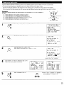
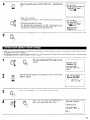
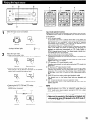
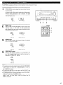
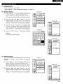
n SAFETY PRECAUTIONS
CAUTION
TO PREVENT ELECTRIC SHOCK, MATCH WIDE BLADE OF PLUG
TO WIDE SLOT, FULLY INSERT.
CAUTION:
A
A
TO REDUCE THE RISK OF ELECTRIC SHOC K,
DO NOT REMOVE COVER (OR BACK). NIO
USER-SERVICEABLE
PARTS INSIDE. REFEiR
SERVICING
TO
QUALIFIED
SERVIC :E
PERSONNEL.
The lightning flash with arrowhead symbol, wrthin
equilateral triangle, is intended to alert the user to
presence of unrnsulated “dangerous voltage” wrthrn
product’s enclosure that may be of sufficient magnitude
constitute a nsk of electric shock to persons
an
t he
t he
to
The exclamation point within an equilateral triangle is intend ed
to alert the user to the presence of important operating and
maintenance
(servicing!
instructions
rn the literate rre
accompanying the appliance.
WARNING:
TO REDUCE THE RISK OF FIRE OR ELECTR
SHOCK, DO NOT EXPOSE THIS APPLIANt
TO RAIN OR MOISTURE.
PouR ~VITER LES CHOCS ~LECTRIOUES, INTERODUIRE LA
LAME LA PLUS LARGE DE LA FICHE DANS LA BORNE
CORRESPONDANTE DE LA PRISE ET POUSSER JUSQU’ AU
This device complies with Part 15 of the FCC Rules. Operation is subject to
the followrng two conditions. (1) This device may rnot cause harmful
interference, and (2) this devrce must accept any interference recerved.
rncludrng Interference that may cause undesrred operatron.
This Class B digital apparatus meets all requirements
Interference-Causing Equrpment Regulations.
of the Canadksn
Cet apparel1 numerique de la classe B respecte toutes les exigences du
Reglement sur le materiel brouilleur du Canada.
n NOTE ON USE / OBSERVATIONS RELATIVES A L’UTILISATION
r
l
l
l
l
l
Keep the set free from moisture, water, and
dust.
Proteger I’apparerl contre I’hurnrdite, I’eau et la
pouss&re.
l
Avord hrgh temperatures.
Allow for sufficient heat dispersion when
installed on a rack.
Eviter des temperatures elevees.
Tenir compte dune dispersion de chaleur
suffisante lors de I’installation sur une etagore.
l
l
l
l
l
Handle the power cord carefully.
Hold the plug when unplugging the cord.
Manrpuler le cordon d’alimentatron avec
precaution.
Tenir la prise lors du debranchement du
cordon.
Unplug the power cord when not usrng the set
for long periods of time.
Debrancher le cordon d’alimentation lorsque
I’appareil rl’est pas utrlrse pendant de longues
periodes.
l
l
* (For sets with ventilatron holes)
l
l
l
2
Do not let foreign objects in the set
Ne pas larsser des objets &rangers dans
I’apparerl.
Do not obstruct the ventilatron holes
Ne pas obstruer les trous d’aeratron.
Do not let rnsectrcides. benzene. and thinner
come rn contact with the set.
Ne pas mettre en contact des insecticides, du
benzene et un diluant avec I’appareil.
Never drsassemble or modify the set rn any
way
Ne jamais demonter ou modifier I’appareil
d’une maniere ou d’une autre
1
i
SAFETY INSTRUCTIONS
1.
Read Instructions - All the safety and operating rnstructions
should be read before the product is operated.
2.
Retain Instructions - The safety and operating
should be retained for future reference.
3.
Heed Warnings - All warnings on the product and in the
operating instructions should be adhered to.
Follow Instructions - All operating and use instructions should
be followed.
4.
instructions
5.
Cleaning - Unplug this product from the wall outlet before
cleaning. Do not use liqurd cleaners or aerosol cleaners.
6.
Attachments - Do not use attachments not recommended by
the product manufacturer as they may cause hazards.
Water and Moisture - Do not use this product near water -for
example, near a bath tub, wash bowl, kitchen sink, or laundry
tub; in a wet basement; or near a swimming pool; and the like.
Accessories - Do not place this product on an unstable cart,
stand, tripod, bracket, or table. The product may fall, causing
serious injury to a child or adult, and serious damage to the
product. Use only with a cart, stand, tripod, bracket, or table
recommended by the manufacturer, or sold with the product.
Any mounting of the product should follow the manufacturer’s
instructions, and should use a
mounting accessory
recommended by the
manufacturer.
A product and cart
combination should be
moved with care. Quick
stops, excessive force,
and uneven surfaces may
cause the product and cart
combination to overturn
Ventilation - Slots and openings in the cabinet are provided for
ventilation and to ensure reliable operation of the product and to
protect it from overheating, and these openings must not be
blocked or covered. The openings should never be blocked by
placing the product on a bed, sofa, rug, or other similar surface.
This product should not be placed in a built-in installation such
as a bookcase or rack unless proper ventilation is provided or
the manufacturer’s instructions have been adhered to.
7.
8.
9.
10
11
12
13
Power Sources -This product should be operated only from the
type of power source indicated on the marking label. If you are
not sure of the type of power supply to your home, consult your
product dealer or local power company. For products intended
to operate from battery power, or other sources, refer to the
operating instructions.
Grounding or Polarization -This product may be equipped with
a polarized alternating-current line plug (a plug having one blade
wider than the other). This plug will fit into the power outlet
only one way. This is a safety feature. If you are unable to
insert the plug fully into the outlet, try reversing the plug. If the
plug should still fail to fit, contact your electrician to replace your
obsolete outlet.
Do not defeat the safety purpose of the
polarized plug.
15
16
17.
18.
19.
20.
21.
22.
23.
24.
25.
Power-Cord Protectlon - Power-supply cords should be routed
so that they are not likely to be walked on or pinched by items
placed upon or against them, paying particular attention to
cords at plugs, convenience receptacles, and the point where
they exit from the product.
Outdoor Antenna Grounding - If an outside antenna or cable
system is connected to the product, be sure the antenna or
cable system is grounded so as to provide some protection
against voltage surges and built-up static charges. Article 810
of the National Electrical Code, ANSYNFPA 70, provides
information with regard to proper grounding of the mast and
supporting structure, grounding of the lead-in wire to an
antenna discharge unit, size of grounding conductors, location
of antenna-discharge unit, connectlon to grounding electrodes,
and requirements for the grounding electrode. See Figure A.
Lightning - For added protection for this product during a
lightning storm, or when it is left unattended and unused for
long periods of time, unplug it from the wall outlet -and
disconnect the antenna or cable system.
This will prevent
damage to the product due to lightning and power-line surges.
Power Lines - An outside antenna system should not be
located in the vicinity of overhead power lines or other electric
light or power circuits, or where it can fall into such power lines
or circuits.
When installing an outside antenna system,
extreme care should be taken to keep from touching such
power lines or circuits as contact with them might be fatal.
Overloading - Do not overload wall outlets, extension cords, or
integral convenience receptacles as this can result in a risk of
fire or electric shock.
Object and Liquid Entry - Never push objects of any kind into
this product through openings as they may touch dangerous
voltage points or short-out parts that could result In a fire or
electric shock. Never spill liquid of any kind on the product.
Servicing - Do not attempt to service this product yourself as
opening or removing covers may expose you to dangerous
voltage or other hazards.
Refer all servicing to qualified
service personnel.
Damage Requiring Service - Unplug this product from the
wall outlet and refer servicing to qualified service personnel
under the following conditions:
a) When the power-supply cord or plug is damaged,
b) If liquid has been spilled, or objects have fallen into the
product,
c) If the product has been exposed to rain or water,
d) If the product does not operate normally by following the
operating tnstructlons.
Adjust only those controls that are
covered by the operating instructions as an improper
adjustment of other controls may result in damage and will
often require extensive work by a qualified technician to
restore the product to its normal operation,
e) If the product has been dropped or damaged in any way, and
f) When the product exhibits a distinct change in performance
-this indicates a need for service.
Replacement Parts -When replacement parts are required, be
sure the service technician has used replacement
parts
specified by the manufacturer or have the same characteristics
as the original part. Unauthorized substitutions may result in
fire, electric shock, or other hazards.
Safety Check - Upon completion of any service or repairs to this
product, ask the service technician to perform safety checks to
determine that the product is in proper operating condition.
Wall or Ceiling Mounting -The product should be mounted to a
wall or ceiling only as recommended by the manufacturer.
Heat -The product should be situated away from heat sources
such as radiators, heat registers, stoves, or other products
(including amplifiers) that produce heat.
3
n INTRODUCTION
Thank you for choosing the DENON AVR-5803 Digital Surround A/V receiver. This remarkable component has been engineered to provide superb
surround sound listening with home theater sources such as DVD, as well as providing outstanding high fidelity reproduction of your favorite music
sources.
As this product is provided with an immense array of features, we recommend that before you begln hookup and operation that you review the
contents of this manual before proceeding.
TABLE OF CONTENTS
q
q
Before Using .........................................
................... ........................ .4
Cautions on Installation.. ............................................
...... .............. .4
Cautions on Handling ...............................................................
......... 5
Features ................. ........................ ............. .............. ... .....
....... .5. 6
Connections .................................................................................... .6-14
Part Names and Functions.. .......................................
............ .15, 16
Setting up the system ..................................................................... ,16-37
Remote Control Unit ..............................................
....................... .37
Operation
. .
...
38-47
m
m
m
m
q
q
q
q
m
0
m
m
q
q
q
Surround........... ............ .... ................ ................ .............. ........48-60
DENON OrIgInal Surround Modes.. ...........................................
.61-65
Listening to the Radio .......................................
66-68
...... ..6 8
Last Function Memory.. ......
... ..................................
Initialization of the Microprocessor.. ..............................................
68
Troubleshooting.................................................................
(69
Additional InformatIon .........................................................
..70-8 1
Specifications ................
........ ......................... .................... .82, 83
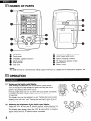
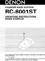
n ACCESSORIES
Check that the following
ci? Operating instructions
AVR-5803.. .................. (1
K-8000 ..................... ..I
parts are included
in addition
to the main unit:
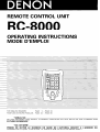
<DWarranty ( for North America model only ). .................. .1 $1 Service station list ............. .1
Cj;lRemote control urilt
@ LRG/AAalkaline batteries . ..4
CT>
AM loop antenna..... .
(RC-8000) ......................
.
(9) FM antenna adaptor,,,,,,, .... 1
@ RC-8001ST.......... lset
@ AC cord .....................
.I
cti>FM indoor antenna.... ..l
RC-8001ST................. .l
0
01
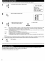
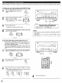
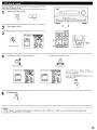
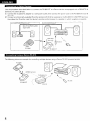
BEFORE USING
Pay attention
l
l
to the following
before using this unit:
Moving the set
To prevent short circuits or damaged wires in the connection
cords, always unplug the power cord and disconnect
the
connection cords between all other audio components when
moving the set.
Before turning the power switch on
Check once again that all connections are proper and that there are
not problems with the connection cords. Always set the power
switch
to the standby
position
before connecting
and
disconnecting connection cords.
Ll2
CAUTIONS ON INSTALLATION
Noise or disturbance of the picture may be generated if this unit or
any other electronic equipment using microprocessors is used near a
tuner or TV.
If this happens, take the following steps:
l
Install this unit as far as possible from the tuner or TV.
l
Set the antenna wires from the tuner or TV away from this unit’s
power cord and input/output connection cords.
l
Noise or disturbance tends to occur particularly when using indoor
antennas or 300 Q/ohms feeder wires. We recommend
using
outdoor antennas and 75 R/ohms coaxial cables.
For heat dispersal, leave at least 10 cm of space between the
top, back and sides of this unit and the wall or other
components.
4
l
l
Store this instructions
in a safe place.
After reading, store this instructions along with the warranty In a
safe place.
Note that the illustrations
in this instructions
the actual set for explanation purposes.
may differ from
03
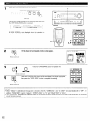
l
l
CAUTIONS
ON HANDLING
Switching
the input function
when input jacks are not
connected
A clicking noise may be produced if the input function is switched
when nothing is connected to the input jacks. If this happens,
either turn down the MASTER VOLUME control or connect
components to the input jacks.
l
Whenever the power switch is in the STANDBY state, the
apparatus is still connected on AC line voltage.
Please be sure to unplug the cord when you leave home for,
say, a vacation.
Muting of PRE OUT jacks and SPEAKER terminals
The PRE OUT jacks and SPEAKER terminals include a muting
circuit. Because of this, the output signals are greatly reduced for
several seconds after the power switch is turned on or input
function, surround mode or any other-set-up is changed. If the
volume is turned up during this time. the output will be very high
after the muting circuit stops functioning. Always wait until the
muting circuit turns off before adjusting the volume.
04
FEATURES
1. Digital Surround Sound Decoding
Featuring dual 32 bit high speed DSP processors, operating
entirely in digital domain, surround sound from digital sources
such as DVD, DTV and satellite are faithfully re-created.
2. Dolby Digital
Using advanced digital processing algorithms, Dolby Digital
provides up to 5.1 channels of wide-range, high fidelity surround
sound. Dolby Digital is the default digital audio delivery system for
North American DVD and DTV, and is available on laser discs as
well as some digital satellite direct-to-home services.
3. DTS (Digital Theater Systems)
DTS provides up to 5.1 channels of wide-range, hiqh fidelity
surrobnd sound; from sources such as laser -disc, bVD an6
specially-encoded music discs.
4. Lucasfilm Home THX Ultra2 Certified
Home THX is the unique collaboration between Lucasfilm Ltd. and
audio equipment manufacturers. THX Ultra2 certification is the
highest performance
level. and provides a rigorous set of
performance standards, along with proprietary surround sound
post-processing technologies, designed to enhance the surround
soundtrack playback experience in the home theater.
In addition to improvements to the power amplifier with respect
to previous THX Ultra standards, two surround modes have been
added: the THX Ultra2 Cinema mode and the THX Music mode.
5. THX Surround EX
The AVR-5803 is fully compatible with THX Surround EX, the latest
surround format.
6. DTS-ES Extended Surround and DTS Neo:B
The AVR-5803 is compatible with DTS-ES Extended Surround, a new
multi-channel format developed by Digital Theater Systems Inc.
The AVR-5803 is also compatible with DTS Neo:6. a surround mode
allowing 6.lchannel playback of regular stereo sources.
7. DTS 96/24 compatibility
The AVR-5803 is compatible with sources recorded in DTS 96/24, a
new multichannel digital signal format developed by Digital Theater
Systems Inc.
DTS 96/24 sources can be played in the multichannel mode on the
AVR-5803 with high sound quality of 96 kHz/24 bits or 88.2 kHz/24 bits.
8. Dolby Pro Logic II decoder
Dolby Pro Logic II is a new format for playing multichannel audio
signals that offers improvements over conventional Dolby Pro
Logic. It can be used to decode not only sources recorded In
Dolby Surround but also regular stereo sources into five channels
(front left/right, center and surround left/right). In addition, various
parameters can be set according to the type of source and the
contents, so you can adjust the sound field with greater precision.
9. Wide screen mode for a 7.1~channel sound even with
5.1-channel sources
DENON has developed a wide screen mode with a new design
which recreates the effects of the multi surround speakers in
movie theaters. The result is 7.1~channel sound taking full
advantage of surround back speakers, even with Dolby Pro Logic
or Dolby Digital/DTS 5.1-channel signals.
lO.Dual Surround Speaker Mode
Provides for the first time the ability to optimize surround sound
reproduction
using two different types of surround sound
speakers as well as two different surround speaker positions:
(I) Movie Surround
Motion picture soundtracks use the surround channel(s) to
provide the ambient elements of the acoustic environment
they want the audience to realize. This IS best accomplished by
the use of specially-designed surround speakers that offer a
wide diffusion pattern (bipolar dispersion) or by using surround
speakers that provide broad dispersion with a minimum of onaxis localization (dipolar dispersion). Side wall mounting (closer
to the ceiling) of the surround speakers provides the greatest
envelopment, minimizing localization of direct sound from the
speakers.
(2) Music Surround
With full range discrete surround channels, as well as three
discrete full range front channels, digital formats such as Dolby
and DTS offer thrilling surround sound music listening.
Producers of multi-channel discrete digital music recordings
almost always favor the use of direct radiating (monopolar)
surround speakers, placed in the rear corners of the room,
since that is how they configure their studios during the
mixing/creation process.
The DENON AVR-5803 provides the ability to connect two
different sets of surround speakers, and place them in the
appropriate locations in your home theater room, so that you
can enjoy both movie soundtracks and music listening, with
optimum results and no compromise.
ll.Multi-zone
control
The AVR-5803 is equipped with two sets of multi-zone outputs
allowing a source other than the one currently being played to be
selected.
(I) Multi-zone 1
These are level adjustable pre-outputs. (A fixed output level
can also be selected.)
The video signals of the input source selected with the multizone 1 selector are output.
(2) Multi-zone 2
When set at the System Setup Menu, the power amplifier for
the surround back channel can be used as the multi-zone 2
power amplifier and speakers can be connected to the multizone 2 speaker terminals for playback.
12.Gomponent Video Switching
The AVR-5803 provides 3 sets of component video (Y, R-Y, B-Y)
inputs for the DVD, TV and DBS/SAT inputs, and one set of
component video outputs to the television, for superior picture
quality.
The AVR-5803 is also equipped with a function for up-converting
composite video or S-Video signals to component video signals.
13.Video Select Function
Allow you to watch one source (visual) while listening to another
source (audio).
5
14Seven Identical Power Amplifiers
Featuring discrete high current power transistors, the power amp
section is THX Ultra certified for top performance with the widest
range of speaker systems. Rated at 170 watts into 8 t/ohms, the
amp channels feature additional low impedance drive capability.
15.Future Sound Format Upgrade Capability via Eight Channel
Inputs & Outputs
For future multi-channel audio format(s), the AVR-5803 IS provided
with 7.1 channel (seven main channels, plus one low frequency
effects channel) inputs, along with a full set of 7.1 channel preamp outputs, controlled by the 8 channel master volume control.
This assures future upgrade possibilities for any future multichannel sound format.
A/D converters are provided for each channel for digital downmixing compatibility.
16Dolby Headphone Compatibility
This is a three-dimensional sound technology developed jointly by
Dolby Laboratories and Lake Technology Ltd. of Australia for
achieving surround sound using regular headphones.
05
CONNECTIONS
Do not plug in the AC cord until all connections have been
completed.
l
Be sure to connect the left and right channels properly (left with
left, right with right).
* Insert the plugs securely, Incomplete connections will result in
the generation of noise.
l
Use the AC OUTLETS for audio equipment
only. Do not
use them for hair driers, etc.
l
6
17.DENON Link
This terminal can be used to connect a Denon DVD player for high
quality digital multichannel playback.
18.Auto Surround Mode
This function stores the surround mode last used for an input
signal in the memory and automatically sets that surround mode
the next time that signal is input.
19.Audio Delay
This is a functton for delaying the audio signal with respect to the
video signal. (0 to 200 msec)
2O.Setup Lock
This is a function that locks the system setup and surround
parameter settings, etc., so that they cannot be changed.
l
l
Note that binding pin plug cords together with AC cords or
placing them near a power transformer will result in generating
hum or other noise.
Noise or humming may be generated if a connected audio
equipment is used independently without turning the power of
this unit on. If this happens, turn on the power of the this unit.
l
When making connections, also refer to the operating instructions of the other components.
R
L
R
L
1 Connecting a tape deck 1
P^..^n..eir..r &.* -a^^.Airr.
1 Connecting
Connect the tape deck’s wording
input jacks (LINE IN 01 RECI to ttw
unit’s tape recordtng (OUT) lacks using pin plug cords
Connections for playback:
Connect the ldpe deck’s playback output jacks (LINE OUT or PBI 10 11115
unit’s tape playback (IN) lacks using pin plug cords
Connecting
the AC OUTLETS 1
AC OUTLETS
standbb from the remote control unit
when llxs wilt’s power IS at standby
No power IS SuppIled from these
Never connect equpment whose total capsc~ty IS above 120 W (1 A.)
NOTE:
-Only use Lhe AC OUTLETS for dudlo equipment Never use them for halr drleis.
outlets
the pre-out jacks
Use these jacks if you wsh to corm
wrease the power of the front, center. surround and surround back sound
channels. or for connection to powered loudspeakers.
Whan using only one surround back speaker. connect it to left channel.
CD player
1 AC outlets
(wall)
1
AC 12OV. 60Hz
/ Connecting
a CD player /
Connect the CD player’s analog
output lacks (ANALOG OUTPUT) to
this un!t’s CD lacks using p!r> plug
cords.
Turntable
(MM cartrldga)
recorder. DAT deck or other component
eqwpped with dlgital Input/output lacks
1 Connecting
a turntable
Extension lacks for future use
1
Connect the turntable’s output cord to the AVR-5803’s PHONO lacks. the
L (left) plug to the L lack, the R lnght) plug to the right lack
NOTE:
This unl cannot be wad wlti MC cartridges directly
head amplifier or step-up transformer
If hummlng or other Norse IS generated
connected, disconnect Ihe ground we
when
CD player or other component
with dIgItal output jacks
Usa a sepalale
the ground
w!re IS
Denon Link terminal
Use this terminal to connect a Denon DVD player for Iugh quality dIgital
multichannel sound.
For details. refel to the DVD player’s operatng uxt~uctons
I Connecting
the DIGITAL jacks
I
Use thase for connec11ow 10 dudlo equlpnient wth dtgltal output
Refer to page 23 for Instructions on settng th6 terminal.
NOTES:
DIGITAL EXT. IN
Extended function for future use
equipped
To connect the video signal, connect using a 75 Q/ohms video signal cable cord. Using an improper
When making connections,
also refer to the operating instructions
of the other components.
l
l
1 Connecting
a TV/DBS tuner
cable can result in a drop in picture
quality.
1
TVIDBS
l Connect the TV’s or DBS tuner’s video output jack (VIDEO OUTPUT) to the m
75 Q/ohms vtdeo coaxial pan plug cord.
. Connect the TV’s or DBS tuner’s audio output jacks (AUDIO OUTPUT) to the m
cords.
(yellow) TV/DES IN jack using a
N/DBS
IN jacks using pin plug
Monitor ni
--
:
R
:
P
I
:
I:
:
:
ip
I
ft
:
s
1 Connecting
a video disc player VDP 1
VDP
l Connect
the video disc player’s video output jack (VIDEO OUTPUT) to the
m
(yellow) VDP IN lack using a 75 Q./ohms video coaxial pin plug cord.
l Connect the video disc player’s analog audio output jacks (ANALOG AUDIO
OUTPUT) to the m
VDP IN jacks using pin plug cords.
l A DVD player can be connected to the DVD jacks In the same way
l It is also posstble to connect a vtdeo disc player, DVD player, video camcorder,
game machine, etc., to the V.AUX jacks
:
:
:
:
:
:
:
I
:
:
1 Connecting
a monitor
TV )
MONITOR OUT
l Connect the TV’s video input
jack (VIDEO INPUT) to the
jVlDEOi MONITOR OUTjack
using a 75 n/ohms video
coaxtal ptn plug cord.
l The tmonttor TV can also be
connected in the same way
to the VIDEO MONITOR
OUT-Z jack.
page 7.
LD player or other component equipped
wth a Dolby DigItal RF output jacks
Video deck 2
equrpped with digital output jacks
NOTES:
Vrdeo output cOnne.ct,~nsfor LD players equrppedwith DolisyDlyttal-RF(AC-3 RFI output jacks.
l
Toconnect an Dolby Dlyital AC-3compatrble LD player to the Dolby D~y~tal-HF
(AC-3RF)jacks.
connect the player’s wdeo outputs to ths unit’s VDP (“put lacks.
l
When the Dolby Dlgrtal-RF(AC-3 RFI xlput selector button on the
p,ctwe switches to the s~ynals,nput to the VDP [“put jdcks
1 Connecting
a video decks
I
There are three sets of video deck (VCR) jacks, so three video decks can be connected for srmultaneous recording ot vrdeo copying.
Video input/output
connections:
l Connect the video deck’s video output jack (VIDEO OUT) to the m
(yellow) VCR-1 IN jack, and the video deck’s video input jack (VIDEO IN) to the /VIDEO
(yellow) VCR-1 OUT jack using 75 Q/ohms video coaxial pin plug cords.
Connecting the audio output jacks
l Connect the video decks audio output tacks (AUDIO OUT) to the /AUDIOI VCR-1 IN jacks, and the video decks audto Input jacks (AUDIO IN) to the m
VCR-1
OUT jacks using pin plug cords.
% Connect the another vtdeo deck to the VCR-2 or VCR-3 lacks In the same way.
l
8
l
l
l
When making connections, also refer to the operating instructions of the other components.
A note on the S input jacks
The input selectors for the S inputs and pin jack inputs work in conjunction with each other.
Precaution when using S-jacks
This unit’s S-jacks (input and output) and video pm jacks (input and output) have independent circuit structures, so that vrdeo signals input from
the S-jacks are only output from the S-jack outputs and video srgnals input from the pin jacks are only output from the pin jack outputs.
When connecting this unit with equipment that is equipped with S-jacks, keep the above point 111mind and make connections according to the
equipment’s instruction manuals.
For a description of the MONITOR OUT terminals, see page 10.
1 Connecting
l
a TV/DBS tuner ]
Connect the TV’s or DBS tuner’s S vrdeo output tack
(S-VIDEO OUTPUT) to the 1-1
:*
:
:
:
I:
:
s
:
:
N/D%
IN
jack using an S jack connection cord.
) Connecting
a video disc player WDPI ]
VDP
. Connect the video disc player’s S-Vrdeo output jack to the
S-VIDEO VDP IN jack using an S-Video connection cord.
. A DVD player can be connected to the DVD jacks In the same
way.
9 It is also oossible to connect a video disc olaver. DVD slaver.
video car&order, game machine, etc., to theV.AUX jacks.
:
f
::
:
:
I(
:
js
:
:m
r
%
:
:
”
::
:s
;
:
:
:*
:
::
onnecting
:,
:
:
::
I
:s
:
*
:
:
:s
:
l
l
the video decks
Connect the video deck’s S output jack GOUT) to the -1
the video deck’s S Input tack (S-IN! to the m
VCR-1 OUT jack using S jack connection cords.
Connect the video deck’s S output jack (S-OUT) to the m
the video deck’s S input jack (S-IN! to the -0
1
VCR-2 OUT jack using S jack connection cords.
VCR-1 IN jack and
VCR-2 IN jack and
0% Connect the third video deck to the VCR-3 jacks in the same way
:
::
”
:
:
“,
~*~,“..
:
s4
:
s.
:
v
%r~rrlalsrrrrs~~~rrspnrrl.nrrP
Connect the components’
1 Connecting a monitor TV ]
MONITOR OUT
l Connect the N’s
or DBS tuner’s S video input (S-VIDEO INPUT!
to the IS-L’IDEOI MONITOR OUT-1 jack u:sing a S jack connection
cord.
l The monrtor TV can also be connected In the same way to the SVIDEO MONITOR OUT-2 jack.
Video deck I
audio Inputs and outputs as described on page 7.
NOTE:
l
The MONITOR OUT-2 output switches together with the input function selected with the REC/M-ZONE 2 button. To use as the monrtor
output, set “SOURCE” as the REC/M-ZONE 2 input function. At this time, the on-screen display signals are output from the video signal
MONITOR OUT-2 (yellow) or S-Video signal MONITOR OUT-2 jack.
9
l
l
l
When making connections, also refer to the operating instructions of the other components
The signals input to the color difference (component) video jacks are not output from the VIDEO output jack (yellow) or the S-Video output jack.
Some video sources with component video outputs are labeled Y, Pa, PR, or Y, Ca, CR, or Y, R-Y, B-Y. These terms all refer to component video
color difference output.
COMPONENT
1 Connecting
a DVD player
1
DVD IN jacks
l Connect
the
DVD
player’s
color
difference
(component) video output jacks (COMPONENT VIDEO
OUTPUT) to the COMPONENT DVD IN jack using 75 Q/
ohms coaxial video pin-plug cords,
l
In the same way, another video source with component
video outputs such as a DlV/DBS tuner, etc., can be
connected to the TV/DE% color difference
video jacks
-1
1 Connecting
a monitor
(component)
TV /
MONITOR OUT jack
l Connect
the TV’s color difference (component)
video input jacks (COMPONENT VIDEO INPUT)
to the COMPONENT MONITOR OUT tack ustng
75 Q/ohms coaxral video pin-plug cords.
l
The color difference input jacks may be indicated differently on sorme
TVs, monitors or video components (“PR, PB and Y”. “R-Y, B-Y and Y”,
“CR. CB and Y”, etc.). For details, carefully read the operatrng
rnstructions included with the TV or other component.
MONITOR OUT jacks
The AVR-5803 is equipped with a function for up-converting video signals.
Because of this, the AVR-5803’s MONITOR OUT jack can be connected to the monitor (TV) with a single cable offering a higher quality connection,
regardless of how the player and the AVR-5803’s video input jacks are connected.
Generally speaking, connections using the component video jacks offer the highest quality playback, followed by connections using the S-Video
jacks, then connections using the regular video jacks (yellow).
% If the AVR-5803’s MONITOR OUT jack is not connected to the monitor (TV) using the component video jacks, connect the player to the AVR5803’s video input jacks using either the video jacks (yellow) or the S-Video jacks. The video signals will not be output if the player and the
AVR-5803 are only connected with the component video jacks.
10
DIRECTION OF
BHOADCASTING
AM LOOP ANTENNA
(SUppllCdl
FM ANTENNA
r-rype C”llWl LW plug ,NcdC”ea
When “s,“g the FM antenna
attach to this apparatus
l
FEEDER
CABLE
?u
75 ~~/ohrn~
COAXIAL
CABLE
FM INDOOR
ANTENNA
(Supplied)
FM ANTENNA
ADAPTER
iSupplied
l
l
300 ilionms
TERMINALS
AM OUTDOOR
ANTENNA
.
An F-type FM antenna cable plug can be connected directly.
If the FM antenna cable’s Dlua- is not of the F-woe, connect usmg
the included antenna adapter.
AM loop antenna assembly
FM antenna
and take ouL the
cmnectfon line.
0
a. With the antenna
on top any stable
surface.
GROUND
adapter assembly
direction.
-+
Ji iv
SCzv
75 Q/ohms COAXIAL CABLE
Connection
Inslallatlbn hole
Mount on wall, etc.
1, Loosen by tummy
counterclockwse.
of AM antennas
2. Insert the
cord
3. Xghten by twnmg
clockvase.
Note to CATV system installer:
Ths remmder IS provided to call the CATV system mstaller’s
that the cable ground shall be contlected Lo the groundmy
system of the bulldlng, as close to the pant of cable entry as
metal parts of the panel.
/
11
l
l
These jacks are for inputting multi-channel audio signals from an outboard decoder, or a component with a different type of multi-channel
decoder, such as a DVD Audio player, or a multi-channel SACD player, or other future multi-channel sound format decoder.
When making connections, also refer to the operating instructions of the other components,
Decoder with 8- or 6channel analog output
F0
-
I
IOOU
-
1
% For instructions on playback using the external input (EXT. IN) jacks, see page 44
l
If another pre-main (integrated) amplifier is connected, the multi-zone jacks can be used to play a different program source in another room at
the same time. (See pages 46, 47.)
RC-616
INFRARED
Extension jacks for future use.
TRlGGkR OUT
DC 12V turns on and off when the product’s power IS turnad on and off
CONTROL ierminai
Perform the following operation before using an external controller connected to the RS-232Cterminal:
1. Press the ON/STANDBYbutton on the maln unit and sat the untt to the operating mode.
2 Perform the operation to turn off the power from the external control.
3. Check that the product has been set to the standby mode.
After checking the above, check the connections of the external controller Operation IS possible.
% For instructions on operations using the MULTI ZONE jacks, see page 43
12
l
l
Connect the speaker terminals with the speakers making sure
that like polarities are matched ( @ with @ , @ wrth 0 ).
Mismatching of polarities will result in weak central sound, unclear
orientation of the various instruments, and the sense of direction
of the stereo being impaired.
When making connections, take care that none of the individual
conductors of the speaker cord come in contact with adjacent
terminals, with other speaker cord conductors, or with the rear
panel.
Speaker Impedance
l
l
l
Speakers with an impedance of from 6 to 16 Q/ohms can be
connected for use as front and center speakers.
Speakerswith an impedance of 6 to 16 R/ohms can be connected
for use as surround speakers.
The protector circuit may be activated if the set is played for long
periods of time at high volumes when speakers with an impedance
lower than the specified impedance are connected
NOTE:
NEVER touch the speaker terminals when the power is on.
Doing so could result in electric shocks.
Connecting the speaker cords
1 Loosenby turning
counterclockwrse.
3. Tightenby turning
2. Insertthe cord
Either tightly twist or terminate
Connecting banana plugs
clockwrse.
the core wires.
Turnclockwiseto tighten,then insertthe
bananaplug.
l
l
l
This unit IS equipped wrth a high-speed protection circuit. The purpose of this circuit is to protect the speakers under
circumstances such as when the output of the power amplifier is inadvertently short-circuited and a large current flows,
when the temperature surrounding the unit becomes unusually high, or when the unit is used at high output over a long
period which results In an extreme temperature rise.
When the protection circuit IS activated, the speaker output is cut off and the power supply indicator LED flashes. Should
this occur, please follow these steps: be sure to switch off the power of this unit, check whether there are any faults
with the wiring of the speaker cables or input cables, and wait for the unit to cool down if it is very hot. Improve the
ventilation condition around the unit and switch the power back on.
If the protection circuit is activated again even though there are no problems with the wiring or the ventilation around the
unit, switch off the power and contact a DENON service center.
The protector circuit may be activated if the set is played for long periods of time at high volumes when speakers with
an impedance lower than the specified impedance (for example speakers with an impedance of lower than 4 Q/ohms)
are connected. If the protector circuit is activated, the speaker output is cut off. Turn off the set’s power, wait for the set
to cool down, Improve the ventilation around the set, then turn the power back on.
The AVR-5803 IS equipped with a cooling fan to prevent the temperature inside the set from rising. The fan is activated
under certain usage conditrons. It is temperature and volume level sensitive, to minimize or prevent audible fan noise.
13
Connections
l
When making
connections,
ConnectIon
jack
for
subwoofer
with bullt-In
ampllfler (super woofer),
also refer to the operating
instructions
FRONT SPEAKER SYSTEMS 1
of the other components
( CENTER SPEAKER SYSTEM
* Precautions when
ccmnecting speakers
If a speaker is placed near
a TV or video monitor, the
colors on the screen may
be dlsturbed
by the
speaker’s magnetism. If
this should happen, move
the speaker away to a
position where it does not
have this effect.
NOTE:
When
14
using only one surround
back speaker, connect
it to left channel.
Ll6
l
0
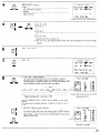
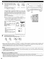
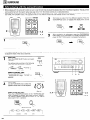
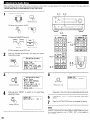
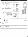
PART NAMES AND FUNCTIONS
For details on the functions of these parts, refer to the pages given In parentheses ( )
Power indicator.. ......................................................................
@ Power switch.. .........................................................................
(38)
@ DSP SIMULATION button .......................................................
(62)
(38)
@ MULTI FUNCTION STATUS button ..........................................
(41)
(41)
@ MULTI FUNCTION MODE SELECT button ............................. (48)
@ DIRECT button.. ......................................................................
(45)
@ MULTI FUNCTION, REC/SELECTOR M-ZONE
@ INPUT MODE selector button .................................................
(39)
0
Headphones jack (PHONES). ...................................................
selector dial (FUNCTION) .......................................................
(42)
(39)
@ MULTI FUNCTION control dial (CONTROL) ............................ (49)
@ EXT. IN button.. .......................................................................
(39)
@ MASTER VOLUME control.. ....................................................
(40)
@ CINEMA/MUSIC button.. ........................................................
(59)
@ Input source indicators ............................................................
(39)
6.1/7.1 SURROUND button .....................................................
(64)
@ Master volume indicator (VOLUME LEVEL). ........................... (40)
@ VIDEO ON/OFF button ............................................................
(45)
@ Display
@ TONE DEFEAT button ...........................................................
(41)
@ Input mode indicators (INPUT MODE) ....................................
(40)
@ M-ZONE 1 button ...................................................................
(43)
@ AL24 indicator ..........................................................................
(40)
@ REC/M-ZONE-2 button ...........................................................
(42)
@ Digital signal indicators (SIGNAL). ...........................................
(40)
@ STEREO button.. ......................................................................
(45)
Q) Surround speaker system indicators
@ DOLBY SURROUND button.. .................................................
(54)
@ DTS SURROUND button ........................................................
(54)
@ PURE DIRECT button ..............................................................
@ WIDE SCREEN button.. ..........................................................
(62)
@ Input source selector dial (INPUT SELECTOR). ....................... (39)
@ 5CH/7CH STEREO button .....................................................
(62)
@ HOME THX CINEMA button ...................................................
0
0
ANALOG button.. .....................................................................
(SURROUND SPEAKER A/B)) ..................................................
(41)
(45)
(51)
@ Remote control sensor (REMOTE SENSOR) .......................... (37)
15
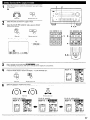
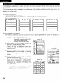
For details, refer to the separate (supplied) K-8000
l
operating instructrons
r
)--
-19
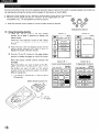
@ Transmitter
@ VOL. (volume) up/down buttons
@ Touch panel
@ LIGHT (back light) button
@ CHANNEL up/down buttons
@ Battery charging contacts
@ MUTE button
@ RF frequency selector switch
@ US6 terminal
@ Reset button
@ Jog stick (PUSH ENTER)
@ Battery cover
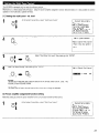
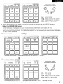
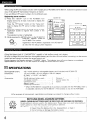
SETTING UP THE SYSTEM
l
l
Once all connections with other AV components have been completed as descrrbed in “CONNECTIONS”
various settings described below on the monitor screen using the AVR-5803’s on-screen display function.
These settings are required to set up the lrstening room’s AV system centered around the AVR-5803.
Use the following buttons to set up the system:
(see pages 6 to 14). make the
Transmrssioncodes
of Independentbuttons
Screen whrle icons are displayed
CHANNELA
CHANNELI
VOLA
VOLI
MUTE
16
: Tuner preset
: Tuner preset
: Main volume of AV amplifier
: Main volume of AV amplifier
: Muting of AV amplifier
l
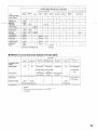
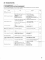
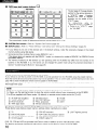
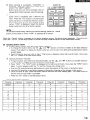
System setup items and default values (set upon shtpment from the factory1
-
System setup
i]
Speaker
Configuratior
(Surround
Speaker
SettIngI
Use this function when using mulbple surround speaker
combtnations for more Ideal surround sound. Once il~e
combmatlons of surround speakers to be “serf for the
different
surround modes are preset, the surround
speakers are selected automatically
accordmg to the
surround mode.
Surround Sp.
Surround Back Sp
St7Xlll
Small
Yes
S”Xll
Small, 2spkrs
nix
THX 6,
~V;ilJE
SCRiE’I
SClV/Ci-I
SFSEO
.gsp
Slii”~-,Oh
%rro~nd
51>8z3i(ll
A
A
A
A
A
Set the irequency (Hz1 below which the bass sound of the “ar,“u~
speakers is to be output from the subwoofer.
Delay Time
This parameter IS for “ptrmlzrng the tlmlng with which the audio
stgndls are produced lrom the speakers and subwoofer according lo
the 11stenrng positron.
THX Audio
Setup
Front Sp.
Sub Woofer
“OLW,
01s
SURROUND
)
When “s,ng a THX Ultra2 compat~bie subwoofer.
set the subwoofer’s frequency response.
Surround Back
Spezxe: Position
When using two surround back speakers,
the distance of the tm’” speakers
-
Al-
Center
12.0 II (3.60 rn)
Sub Woofer
Surr”“nd
12.0 II (3 60 I‘(I) 12 0 ft (3 60 m)
-
Front L
Front R
Center
0.0 dB
0.0 dB
OOdB
SBL & SBR
10 0 II 13.00 mi
S”rlo”nd
Sumund
R
S”W”“d
aaar i
Surround
aacl, R
OOdB
0.0 dB
OOdB
0.0 dB
THX Ultra2 Subwoofer
set
L& R
10.0 ft (3 00 ml
The Distance Between
Subwoofer
0.0 dB _
= NO
SBUSBR = 0 ft to 1 ft (0 rm to 0.3 ml
This parameter 1s for detecung the max~mun~ level of the low b&s
signals output from the subwoofer channel I” order to protect the
subwoofer from damage and prevent unpleasant distorted sounds
from being produced.
Peak Lamlter = OFF
V!deo Input
Mode
Set the input stgnal to be output from the momtor output terminal.
AUTO
Audio Delay
Adjust the time delay of the wdeo and dudio sbgnals.
Subwoofer
Peak Limit
LeV
-
LFE -THXFront L & R
This adjusts the volume of the signals output from the speakers and
subwoofer for the different channels m order to obtain optmwrn
effects.
Boundary Gam
compensation
Ib%L-i (11
DlHECT
FIXED -THX-
-.Suhwoofermode This selects the subwoofer speaker for playmy deep bass signals
Channel
Level
I
Center sp
~~~~~~~~~
r;,fiOe
hSS”W
Frequency
D
00
3
3
-4
-D
0
iiD
aP
9
-$
-
Default settmgs
I
Input the combmation
of speakers 111your system and their
correspondmy s,zes (Small for regular speakers. Latyr for full-ale,
full-range) to automatically set the composmon of the slgnrrls output
from the speakers and the frequency response
Diyital In
Assignment
Multi Zone
Control
Mutt, Zone1
vol. Level
This sets the output
lacks.
level for the multi-LO”~
Power AMP
Assignment
Sel thrs 1” watch the surround back channel’s
power amplifier for use for multi-zone 2.
output
Audi” Delay = 0 ms
1
4uto SJrround
Mode
Auto surround mode function
Ext. In Setup
Set the Ext.ln terrnmal playback method
Digital Multi
Ch In
Drgrtal multichannel
on Screen
Display
This sets whether or nor to display the “n-screen display that
appears on the monrtor xreen when the controls on the remote
control unit or main unit ere operated (from MONITOR 1 outputs
Only)
4uto Tuner
Presets
Setup Lock
Vamble
Surround Back
Auto Surround Mode = ON
setting.
MODE = DSP. S.Back = NOT USED, SW Level = +15 dB, INPUT Vol = 0 dB
I
DENON Link = OFF, DIgItal Ext. In = OFF
input setting.
On Screen Display = ON
1 Al-AS
FM stations are recwed
automatally
dnd stored I” the memory.
Set whether or not to lock the system setup settings so that they
cannot be changed
1 87 5/89 l/98 l/107.9/90.1/90
Bl -68
520/600/l 00011400/1500/1710
Cl -C8
90.1 MHz
Dl ,.D8
90.1 MHz
El -E8
90.1 MHz
l/90.1/90.1
MHz
kHz/90.1/90.1
MHz
Setu(> Lock = OFF
17
NOTES:
l
The on-screen display signals are output with priority to the S-VIDEO MONITOR OUT jack during playback of a video component. For
example, if the TV monitor is connected to both the AVR-5803’s S-Video and video monitor output jacks and signals are input to the AVR5803 from a video source (VDP, etc.) connected to both the S-Video and video input jacks, the on-screen display signals are output with
priority to the S-Video monitor output. If you wish to output the signals to the video monitor output jack, do not connect a cord to the SVIDEO input jack. (For details, see page 37.)
l
The AVR-5803’s on-screen display function is designed for use with high resolution monitor TVs. so it may be difficult to read small
characters on TVs with small screens or low resolutions.
l
The setup menu is not displayed when headphones are being used.
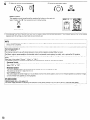
Speaker system layout
Basic system layout (For a THX Surround EX system)
l
The following is an example of the basic layout for a system consisting of eight speaker systems and a television monitor:
l
C-Center
rsubwoofer
speaker systenl
-
Set these at the sides of the TV or screen with
their front surfaces as flush with the front of the
screen as possible.
I
Surround back speaker systems
Surround speaker systems
Two surround back speakers are required to use the THX Ultra2 Cinema and THX MUSIC modes.
Set the surround back speakers so that the distance to the listening point is the same for both the left and right speakers. It is also recommended
that the deviations of the distance from the listening position to L and R channel speakers (front left (FL) and front right (FR), surround left (SL)
and surround right (SR), surround back left (SBL) and surround back right (SBR)) is less than 2 ft (60 cm).
With the AVR-5803 it is also possible to use the surround speaker selector function to choose the best layout for a variety of sources and surround
modes
l
Surround speaker selector function
This function makes it possible to achieve the optimum sound fields for different sources by switching between two systems of surround
speakers (A and 8). The settings of the different speakers (A only, B only or A+B) are stored in the memon/ for the different surround modes,
so they are set automatically when the surround mode is selected.
I----I----’
I----’
I
’
L- - - -I L-- - I ’L - - -- I
r---1
I
L----
I----I ’I-----
1----I ’L---l
(SB: Surround Back Speakers)
Using A only
(Multi surround speaker system)
L
18
Using B only
(Single surround speaker system)
1
2
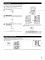
ON,SN\NDBY
Check that all the connections are
correct, then turn on the main unit’s
power.
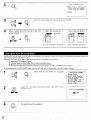
1
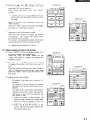
Either lightly press on the remote control unit’s touch panel
or press the LIGHT button to turn on the liquid crystal display.
(The back light does not turn on when the touch panel is
pressed.)
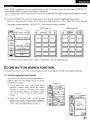
2,5,6.7,6
3
4
By default the liquid crystal display is set to display for 30
seconds, but this can be changed to approximately 120
seconds using the procedure described below so that
operations during system up can be performed securely.
MI-
Lightly press the remote control unit’s
jog stick (PUSH ENTER) to display the
icon disolav section.
Press the “ v
” button in the icon display section to display
the “AVAMP” icon.
Press the “AVAMP” Icon to display the page section.
5
Press the ” 7
” button in the icon display sectton to display
the “SETUP” icon.
Push the remote control unit’s jog stick
to the right to display the “SETUP 3/5”
page.
6
7
Press the “SETUP” icon for at least 3 seconds to display
the setup screen.
Push the remote control unit’s jog
stick to the right to display the “SETUP
414” page.
Press the “LCD 30s” button on this
page so that this part is displayed in
half-tone dot mesh.
Press “SYSTEM SETUP” at the bottom left to display the
“System Setup Menu” on the TV screen.
System
Setup
Menu
FSpeaker
Configuration
Delay Time
Channel
Level
THX Audio Setup
SubrooferPeak Limit
Lev.
Digital
In Assignment
kldeo
Input
Mode
Now press the “A” button to set the
time display to ” 120”.
19
l
The composition of the signals output from the different
combination of speakers actually being used.
channels and the frequency response are adjusted automatically
according to the
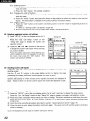
Press “CURSOR/PAGE” at the center of the bottom line on the “AV AMP’s” “SETTING 3/5” page so
that this part is displayed in half-tone dot mesh.
Make the system setups by pushing the jog suck on the remote control unit forward and backward, left
and right.
2
3
4
At the System Setup Menu select “Speaker Configuration”
lwnmln
Switch to the speaker configuration
Set whether or not speakers are
connected and, if so, their size
parameters.
l
To select the speaker
l
screen
Speaker
Speaker
Configuration
Configuration
&rround
center sp.
To select the parameter
Subwoofer
Surround Sp. A
Surrowd
back Sp
Surround Sp. B
5
,
Enter the setting.
a) If no surround speakers are used (if “None” is set for both A and 6):
The Crossover Frequency screen appears.
b) If both surround speakers A and B are used (if either “Large” or “Small” is set for both A and B):
The surround speaker setting screen appears.
c) When “Front” is set to “Large” and “Subwoofer” is set to “Yes”, the set switches to the subwoofer mode
d) If “None” is set for surround speakers A:
“None” is automatically set for surround speakers B and surround back speaker.
NOTE:
l
Select “Large” or “Small” not according to the actual size of the speaker but according to the speaker’s capacity for playing low frequency
(bass sound below frequency set for the Crossover Frequency mode and below) signals. If you do not know, try comparing the sound at both
settings (setting the volume to a level low enough so as not to damage the speakers) to determine the proper setting.
20
l
I
%
%
%
l
Parameters
Large................Select
this when using speakers that can fully reproduce low sounds of below 80 Hz.
Small .. .. .. .... .... ..Select this when using speakers that cannot reproduce low sounds of below 80 Hz with sufficient volume.
When this setting is selected, low frequencies of below 80 Hz are assigned to the subwoofer.
None .._.. ._....._.Select this when no speakers are installed.
Yes/No... .... .... ..Select “Yes” when a subwoofer is installed, “No” when a subwoofer is not Installed.
Zspkrs/lspkr.....Select
the number of speakers to be used for the surround back channel.
If the subwoofer has sufficient low frequency playback capacity, good sound can be achieved even when “Small” is set for the front, center
and surround speakers.
To take full advantage of the performance of the Home THX certified speaker systems, set the front, center and surround speaker size
parameters to “Small” and the subwoofer to “Yes”.
For the majority of speaker system configurations, using the SMALL setting for all five main speakers and Subwoofer On with a connected
subwoofer wilt yield the best results.
When “Front” is set to “Small”, “Subwoofer” is automatically set to “Yes”, and when “Subwoofer” is set to “No”, “Front” is automatically
set to “Large”.
At this screen preset the surround speakers to be used in the different surround modes.
1
mmlemn
f
0
4
When either “Large” or “Small” has been set for both speakers A and B
on the System Setup Menu (when using both A and B surround speakers).
the surround speaker setting screen appears.
Select the surround speakers to be used in the different surround modes.
l
To select the surround mode
l
To select the surround speaker
A:
When using surround speakers A
B:
When using surround speakers B
A+B: When using both surround speakers A and B
2
MI-
Enter the setting.
When “Front” is set to “Large” and “Subwoofer”
is set to “Yes”, the set swatches to the subwoofer
mode
.% Speaker type setting when using both surround speakers A and B
If “Small” is set for either surround speakers A or B, the output is the same as when “Small” is set for both A and B.
2G For the “WIDE SCREEN” and “5ffCH STEREO” DSP simulation modes, the surround speakers can be set separately.
Set the crossover frequency and subwoofer
1
mode according to the speaker system being used.
Select the Crossover Frequency mode
To select the Crossover Frequency.
rl
rl
21
WUI-
2
Crossover
Enter the setting.
The System Setup Menu reappears.
frequency
Set the frequency (Hz) below which the bass sound of each main speakers is to output from the subwoofer or from speakers which are set to
“Large” (when not using a subwoofer) (crossover frequency).
For speakers set to “Small”, sound with a frequency below the crossover frequency is cut, and instead the cut bass sound IS output from the
subwoofer or speakers which are set to “Large”.
This crossover frequency mode is valid when “Subwoofer” IS set to “Yes” at “Speaker Configuration Setting” or when speakers are set to
“Small”.
l
l
l
FIXED -THX-:
Set to the THX rated 80 Hz crossover frequency.
VARIABLE 40,60,80,100,120
Hz:
Set as desired according to your speakers’ bass playback ability.
NOTES:
The crossover frequency is set to 80 Hz in the HOME THX CINEMA mode.
We recommend using with the crossover frequency set to “FIXED -THX-“,
may improve frequency response near the crossover frequency.
l
l
1
f
Rmsrm
Select the subwoofer
mode.
but depending on the speaker, setting it to a different frequency
Crossover
iisubwoofer
2
Msna
Frequency
Mode
I
Enter the setting.
The System Setup Menu reappears
NOTES:
- Assignment of low frequency signal range l
The only signals produced from the subwoofer channel are LFE signals (during playback of Dolby Digital or DTS signals) and the low
frequency signal range of channels set to “Small” in the setup menu. The low frequency signal range of channels set to “Large” are
produced from those channels.
- Subwoofer mode l
l
l
l
22
The subwoofer mode setting is only valid when “Large” is set for the front speakers and “Yes” is set for the subwoofer in the “Speaker
Configuration” settings (see page 20).
When the “LFE+Main” playback mode is selected, the low frequency signal range of channels set to “Large” are produced simultaneously
from those channels and the subwoofer channel.
In this playback mode, the low frequency range expand more uniformly through the room, but depending on the size and shape of the room,
interference may result in a decrease of the actual volume of the low frequency range.
Selection of the “LFE - THX” play mode will play the low frequency signal range of the channel selected with “Large” from that channel
only. Therefore, the low frequency signal range that are played from the subwoofer channel are only the low frequency signal range of LFE
(only during Dolby Digital or DTS signal playback) and the channel specified as “Small” in the setup menu. THX is recommended in this play
mode so that bass interference is less likely to occur in the room.
Select the play mode that provides bass reproduction with body.
l
l
l
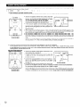
Input the distance between the listening position and the different speakers to set the delay time for the surround mode.
The delay time can be set separately for surround speakers A and B.
Two surround back speakers are required to use the THX Ultra2 Cinema and THX Music modes.
Set the surround back speakers so that the distance to the listening point is the same for both the left and right speakers.
It is also recommended that the deviations of the distance from the listening position to L and R channel speakers (front left (FL) and front right
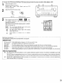
(FR), surround left (SL) and surround right (SR), surround back left (SBL) and surround back right (SBR)) IS less than 2 ft (60 cm).
Preparations:
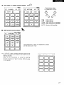
Measure the distances between the listening position and the speakers (Ll to L6 on the diagram at
the right).
Ll: Distance between center speaker and listening position
L2: Distance between front speakers and listening positron
L3: Distance between surround speakers and listening position
L4: Distance between surround back speakers and listening position
L5: Distance between subwoofer and listening position
L6: Distance between surround back L and surround back R
1
FL
t
Suhwor
At the System Setup Menu select “Delay Ime”.
Speaker
Configuration
uDelay
Time
Channel
Level
THX Audio
Setup
S~lwooftr
Peak Limit
Lev.
Digital
In Assignment
ildeo
Input
Mode
I----2
III-
Switch to the Delay Ime screen
Delay
Time
Set The Distance
Each Speakers
Do You Prefer
In Meters?
/
FMeters
Select the desired unit, meters or feet.
Select (darken) the desired units, “Meters”
or “Feet”
Delay
4:)
To
In Feet?
Feet
Time
Set The Distance
Each Speakers
Do You Prefer
In Meters?
/
uMeters
4:)
To
In Feet?
@ZI
Example: When “Feet” is selected
4
Once “Meter” or “Feet” is selected in Step 3, the
Delay Time screen appears automatically.
Select the speaker to be set.
Delay
Time
Step
Default’
% When “Step” IS selected, it is possible to
switch between “1 ft” and “0.1 ft”.
23
6
lUlMP
Set the distance between the
center speaker
and listening
position.
The distance changes in units of
0.1 foot (0.03 meters) each time
the button is pressed. Select the
value closest to the measured
distance.
6L
A
410. Oft,
Example: When the distance is set to 12 feet
for the center speaker
% If “Yes” is selected for “Default”,
to the default values.
the settings are automatically
reset
Please note that the difference of distance for every speaker should be 20
ft (6.0 m) or less. If you set an invalid distance, a CAUTION notice, such
as screen right will appear. In this case, please relocate the blinking
speaker(s) so that Its distance is no larger than the value shown in
highlighted line.
7
l
l
l
l
Mwm
Enter the setting.
The System Setup Menu reappears.
The AVR-5803 automatically sets the optimum surround delay time for the listening room
Use this setting to adjust so that the playback level between the different channels is equal.
From the listening position, listen to the test tones produced from the speakers to adjust the level
The level can also be adjusted directly from the remote control unit. (For details, see page 48.)
When using both surround speakers A and 6, their playback levels can be adjusted separately.
At the System Setup Menu select “Channel Level”
System Setup Menu
1Speaker
Configuration
Delay Time
FChanne I Leve I
THX Audio Setup
SuhroofrrPeak Limit
Lev.
Digital
In Assignment
;ideo
Input Mode
2
3
24
-(*(I
Switch to the Channel Level screen
Select “Test Tone Mode”
Channe I Leve I
ETest
Tone
ml
:b@Zl
Test
Tone
Start
m(
4
MlWll
Select the mode.
Select “Auto” or “Manual”.
l
Auto:
Adjust the level while listenrng to the test tones produced automatically
from the different speakers.
l
Manual:
Select the speaker from which you want to produce the test tone to
adjust the level.
_...--~-..-.--~-----_-----~IFTest Tone
m*:r@Zl
Test
Tone
Start
m(
Example:When the “Auto” mode is selected
5
6
)uI- t
I
0 I
4
lulmnl
Select ‘Burr. Sp.“, then select the surround speaker(s) from which you want to produce the test
tone (A, 6 or A+B).
l
Surr. Sp.: A
Adjusts the balance of the playback level between the channels when using surround speaker
A.
l
Surr. Sp.: B
Adjusts the balance of the playback level between the channels when using surround speaker
B.
l
Surr. Sp.: A+B
Adjusts the balance of the playback level between the channels when using surround
speakers A and B at the same time.
% The “Surr. Sp.” can only be selected when both surround speakers A and B have been
selected at the “Speaker Configuration” (when both A and B have been set to “Large” or
“Small”).
Select “Test Tone Start”
tI
a
+
Channel
8
Level
Test
Tone
m4
:tlr(n.l
Surr.
Sp.
!%B
At6
a. If the “Auto” mode is selected:
Test tones are automatically emitted from the different speakers.
The test tones are emitted from the different speakers in the
following order, at 4second Intervals the first time and second time
around, 2-second intervals the third time around and on:
% When the surround back speaker setting is set to “lspkr”
“Speaker Configuration”, this is set to “SB”.
for
Example: When the volume is set to -11.5 dB
while the test tone is being
produced from the FL
Use the CURSOR buttons to adjust at1 the speakers to the same
volume.
The volume can be adjusted between -12 dB and +I2 dB in units of
0.5 dB.
b. When the “Manual” mode is selected
Move jog stick “ENTER” back and forth to select the speaker for which
you want to output test tones, then move jog stick “ENTER” left and
right to adjust so that the volume of the test tones from the various
speakers is the same.
Test
Tone
m
G-FL
C
/
/
Flashing
EF:
SBR
SBL
Ev
0. OdB
txampre: When the volume is set to -11 5 dB
while the FL ISselected.
9
After the above settings are completed, press jog stick “ENTER”
The “Channel Level” screen reappears.
Press jog stick “ENTER” again to return to the System Setup Menu screen.
3%To cancel the settings, select “Level Clear” and “Yes” on the “Channel Level” screen, then make the settings again
The level of each channel should be adjusted to 75 dB (C-weighted, slow meter mode) on a sound level meter at the listening position
If a sound level meter is not available adjust the channels by ear so the sound levels are the same. Because adjusting the subwoofer level test
tone by ear is difficult, use a well known music selection and adjust for natural balance.
NOTE: When adjusting the level of an acttve subwoofer system, you may also need to adjust the subwoofer’s own volume control.
% When you adjust the channel levels while in the SYSTEM SETUP CHANNEL LEVEL mode, the channel level adjustments made will affect
ALL surround modes. Consider this mode a Master Channel Level adjustment mode.
% After you have completed the SYSTEM SETUP CHANNEL LEVEL adjustments, you can then activate the individual surround modes and
adjust channel levels that will be remembered for each of those modes. Then, whenever you activate a particular surround sound mode,
your preferred channel level adjustments for just that mode will be recalled. Check the instructions for adjusting channel levels within each
surround mode on page 48.
I You can adjust the channel levels for each of the following surround modes: DIRECT, STEREO, 5CH/7CH STEREO, DOLBY/DTS SURROUND,
HOME THX CINEMA, WIDE SCREEN, SUPER STADIUM, ROCK ARENA, JAZZ CLUB, CLASSIC CONCERT, MONO MOVIE, and MATRIX.
% When using either surround speakers A or B, or when usrng surround speakers A and 6 at the same time, be sure to adjust the balance of
playback levels between each channel for the various selections of “A or B” and “A and B”.
Make these settings when “Yes” is selected for the subwoofer in the Speaker Configuration settings
There is not displayed when “No” selected. (page 20)
1
2
Select “THX Audio Setup” on the System Setup Menu screen
System
Setup
Menu
Speaker
Configuration
Delay Time
Channe I Leve I
FTHX Audio
Setup
SubwooftrPeak Limit
Lev.
Digital
In Assignment
;ideo
Input Mode
Nmmu
Press jog stick “ENTER” to switch to the THX Audio Setup screen
Select “Boundary Gain Compensation”,
jog stick “ENTER”.
then press
THX Audio
Setup
uBoundary
Gain
Compensation
Surround
Speaker
Exit
26
Back
Position
I
4
When using a THX Ultra2 compatible subwoofer or subwoofer that
frequency response extends to 20 Hz, select “Yes”. Otherwise select
“No”.
uDo You Have
A THX Ultra2
Subwoofer
(Or Sub That
Ex+&;;s,&
20Hz) ?
:
.
l-----l
l
l
5
l
l
Mmlu
When “Yes” is selected
“Boundary Gain Compensation”
set to “OFF”.
can be selected and the compensation
If the bass sound seems too strong
Set “Boundary Gain Compensation” to “ON”. This activates a circuit
that cuts the low frequencies of 55 Hz and under. Select “ON” or “OFF”
according to how strong you like the bass sound to be.
uDo You Have
A THX Ultra2
Extends
Subwoofer
To 20Hz)?
Press jog stick “ENTER” to return to the THX Audio Setup screen.
When two surround back speakers have been set in the Speaker Configuration settings (page 20). set the distance of the speakers. There is
not displayed when “1 spkr” selected.
This setting is necessary to achieve the optimum effect in the THX Surround EX, THX Ultra2 Cinema and THX Music modes. It is recommended
that SBUSBR speakers are placed together as close as possible.
1
Select “Surround Back Speaker Position” on the
THX Audio Setup screen, then press jog stick
“ENTER”.
THX Audio
Setup
Boundary
Gain
Compensation
6urround
Speaker
Back
Position
Exit
2
?lR4mm
Select the settings according to the distances of the two surround back
speakers. (page 23)
0
Set The Distance
Between SBL/SBR
4
cw
3
4
Mmlu
oft to
(Om to
lft
0. 3m)
)
Press jog stick “ENTER” to return to the THX Audio Setup screen
Select “Exit” then press the ENTER button
return to the System Setup Menu screen.
to
Boundary
Gain
Compensation
Surround
Speaker
Back
Position
27
l
l
This unit features a subwoofer peak limit control which prevents distortion and damage in the loudspeaker system by controlling the maximum
bass volume level. With this feature you may set the maximum bass level for the system.
This feature operates with or without a subwoofer in the system.
1
At the System Setup Menu select “Subwoofer
Peak Ltmit Lev.”
I
wwlll
2
System
Setup
Menu
Speaker
Configuration
Delay Time
Switch to the Subwoofer Peak Limit Level Setting screen.
Limit
Level
Setting
Find The Level
When
Distortion
Begins.
crPeak
Limiter
m4:Im
Select “ON” for Peak Limiter.
4
The screen switches.
a
8
*
G
cfl
Select “Setting
Start”,
then
The screen swatches and a test noise is produced
~~~:he”,“,eak~r
system.
Limit
Level
Setting
Find The Level
When
Distortion
Begins.
RPeak Limiter
Setting
Start
5
*oI
Increase the master volume level until the test noise is distorted.
The test noise (bass sound) is distorted when it sounds as if the input is
excessively high (when the sound crackles).
C Peak
Limiter
Limit
Level
Turn
Master
m4:bm
WI
-181
1
Setting
Up The Volume
Vol.
@
Button
When Distortion
Begins
Push Enter
Button.
6
lulmlm
% Clear the subwoofer’s
28
Press the ENTER button at the point where the test noise starts sounding distorted.
The AVR-5803 automatlcally sets the subwoofer peak limit level.
This prevents future inadvertent subwoofer overload due to excessively strong bass content when the master
volume control is at a high level.
peak limit level setting by specifying “Peak Limiter” and “OFF”
CAUTION!
l
The master volume is set to “-30 dB” when test tones are output.
l
The test tones are for confirming the low frequency playback limits and are played at an extremely high level. When using a low output
subwoofer, be very careful about irregular operations exceeding clipping by for example turning down the subwoofer’s attenuator before
starting then slowly turning the attenuator up to the listening level.
l
Also, when the subwoofer is set to “NO” in the speaker configuration, the test tones are output from the front speakers. When using front
speakers with low input resistance, check that the sound is not clipped at sections where the signal is strong on the CD music source before
starting the peak limit setting. The peak limit setting should not be performed if the music source cannot be played with the master volume
set at “-15”. Set the front speakers to “small” and the subwoofer to “YES” in the speaker configuration. When this is done, the low
frequencies are cut, so the effect is insufficient. We strongly recommend adding a subwoofer.
l
If the test tone is clipped when it is set to “-18 dB”, set the peak limit to “-18 dB”. In this case, the input resistance of the subwoofer or
front speakers is insufficient so clipping may occur when playing music. We recommend switching to a subwoofer with a higher input
resistance.
I
I
l
This setting assigns the digital input jacks of the AVR-5803 for the different input sources.
1
MBml
t
At the System Setup Menu select “Digital In Assignment”.
.
I
NW-
System
Setup
Menu
Speaker
Configuration
Delay Time
Channel
Level
THX Audio Setup
SuhwophrPeak Limit
Lev.
EDigital
In Assignment
gideo
Input
Mode
4
2
r
Switch to the Digital In Assignment
J
screen
Digital
rm:4COAXlb
In Assignment
m:
COAX5
Default@94
3
u(itme
f
I
-c
4
Mm
MUOE
Select the dtgital input jack to be assigned to the input source.
l
To select the input source
l
To select the digital input jack
Select “OFF” for input sources for which no digital input jacks are used.
a If “Yes” is selected for “Default”, the settings are automatically reset to the default values.
Enter the setting.
The System Setup Menu reappears.
NOTES:
l
The OPTICAL 5 and 6 jacks on the AVR-5803’s rear panel are equipped with an optical digital output jack for recording digital signals on a
DAT deck, MD recorder or other digital recorder. Use this for digital recording between a digital audio source (stereo - 2 channel) and a digital
audio recorder.
l
Do not connect the output of the component connected to the OPTICAL 5 OUT lack on the AVR-5803’s rear panel to any jack other than the
OPTICAL 5 IN jack.
l
Do not connect the output of the component connected to the OPTICAL 6 OUT jack on the AVR-5803’s rear panel to any jack other than the
OPTICAL 6 IN jack.
l
“PHONO” and “TUNER” cannot be selected on the Digital In Assignment screen.
29
l
Select the input signal to be output from the video monitor output terminal. (For details, refer to page 81.)
At the System Setup Menu select “Video Input Mode”
System
Setup
Menu
Speaker
Configuration
Delay Time
Channel
Level
THX Audio
Setup
SubwooftrPeak Limit
Lev.
Digital
In Assignment
Wide0
Input
Mode
0
2
Mill
Switch to the Video Input Mode screen.
m:
Video
lnpu t Mode
b
4AUTO
m:
AUTO
m:
AUTO
m:
AUTO
Iv.AuxI: AUTO
Default
E44
3
cl?
\.. Select the input source for which you
want to set the Video Input Mode.
AUTO:
Component:
S-Video:
Video:
G? Select the mode
When there are multiple input signals, the Input signals are detected and the Input signal to be output from the video
monitor output terminal is selected automatically in the following order: component video, S-Video, composite video.
The signal connected to the component video terminal is always played.
Video conversion is not conducted, so no image is output from the monitor output terminal when there is no input signal
to the component terminal.
Only DVD, TV and DBS can be selected.
The signal connected to the S-Video terminal is always played.
The S-Video input signal is up-converted and output from the component monitor output terminal.
The signal connected to the composite video terminal is always played.
The composite video input signal is up-converted and output from the S-Video and component monitor output terminals.
NOTE:
Down-converting from the component video signal to the S-Video and composite video signal IS not possible, so when not using the
component video monitor output terminal connect the player using the S-Video or composite video input terminal.
4
MI-
Enter the setting.
The System Setup Menu reappears.
This function allows you to adjust the time delay of the video and audio signals and store these settings for the different input sources
The setting is made while watching a DVD or other software, so it is not made here.
By default, this is not displayed when no digital signals are being input.
For instructions on making the setting, refer to page 56.
30
The AVR-5803 is equipped with two sets of multi-zone outputs.
Multi-zone 1 is a pre-output with an output level adjustment function.
Multi-zone 2 is a fixed output level pre-output. Using the power amplifier assignment function described below, it is also possible to connect
speakers to the multi-zone 2 speaker terminals.
Ill
Setting the multi-zone
1 vol. level
At the System Setup Menu, select “Multi Zone Control”.
Digital
Mul’ti
Ch In
On Screen
Display
Auto Tuner Presets
Setup Lock
2
Press jog stick “ENTER” to switch to the “Multl Zone Control” screen
WDnm
Multi
Multi
Power
Zone
Zone1
Control
Vol. Level
Amp Assignment
Exit
3
4
Select “Multi Zone1 Vol. Level” then press jog stick “ENTER”.
Mmam
MIDam
t
Select the desired setting, then press log strck “ENTER”
nmmmm
I(ROllE
I
Multi
Zone1
Vol. Level
OdB
*
Variable:
The level can be adjusted freely using the buttons on the remote control unit (M. ZONE 1 4/5,
VOLUME UP and VOLUME DOWN).
I
-40 cl%, 0 d%:
The output level is fixed at the set level and the volume can no longer be adjusted.
[Zl Power amplifier
assignment
function
setting
Make this setting to switch the power amplifier for the surround back channel to Multi-zone 2.
System Setup Menu
@
Audio Delay
Multi
Zone Control
Auto Surround
Mode
Ext. In Setup
Digital
Multi
Ch In
On Screen
Display
Auto Tuner Presets
Setuo Lock
31
Press jog stick “ENTER” to switch to the “Mutt1 Zone Control” screen.
Multi
%lulti
Power
Zone
Zone1
Control
Vol.Level
Amp Assignment
Exit
l-----l
3
M(yII
--
t
:
Select “Power Amp Assignment”
then press jog stick “ENTER”
e
4
4
Select “Surround Back” to use as the surround back
channel, “Zone-Z” to use as multi-zone 2, then press
jog stick “ENTER”.
Power
I-
Amp Assignment
: M-ZonePb
When “Surround Back” is selected
’
Power
Amp Assignment
4 Surroundbck: B
When “M-Zone2”
is selected
The surround mode last used for the four types of input signals shown below is stored in the memory and the signal is automatically
that surround mode the next time it is input.
Note that the surround mode setting is also stored separately for the different input sources.
G>
g
$
&
played with
Analog and PCM Z-channel signals
2-channel signals of Dolby Digital,, DTS or other multichannel format
Multrchannel srgnals of Dolby Drgrtal, DTS or other multtchannel format
Multi-channel signal when conducting playback using the EXT.IN-I, EXT.IN-2 and DENON LINK terminals
I During playback in the PURE DIRECT mode, the surround mode does not change even if the input signal is changed
1
2
3
32
Mm-m
f
0
8
nmm
MIlR
Select “Auto Surround Mode” on the System
Setup Menu screen, then press jog stick “ENTER”
System
Setup
Menu
Audio
Delay
Multi
Zone Control
EAuto Surround
Mode
Ext. In Setup
Digital
Multi
Ch In
On Screen
Display
Auto Tuner Presets
Select “ON” if you want to use the auto surround mode, “OFF” if you do
not want to use it.
Enter the setting.
The System Setup Menu reappears
Auto
Surround
Mode
l
Set the method of playback of the analog input signal connected to the Extln-1 and Ext.ln-2 terminal
1
f
mmmlm
At the System Setup Menu select “Extln
Setup”.
System Setup Menu
M
Audio Delay
Multi Zone Control
Auto Surround Mode
uExt. In Setup
Digital
Multi Ch In
On Screen Display
Auto Tuner Presets
Setuo
Lock
Switch to the Extln Setup screen
FEXT. I N-l
EXT. IN-2
EXIT
3
ci> Select the input terminal.
Illm
3 Switch to the setting screen.
luwslls
f
EXT. IN-1
Setup
a
%
6
4
HIIRon
Select the item to be set (push the jog stick to the
up and down) then select the parameter (push the
jog stick to the left and right).
f
lulWlU
0
Hvfode
S Back
SW Level
Input
Vol.
:NOKSED:
4 +lzE$ ;
1
J
+
MODE:
DSP:
ANALOG:
The analog input signal IS converted into a digital signal and undergoes DSP processrng.
System Setup settings (speaker configuration, channel delay, etc.) are reflected in the same way as for other Input signals.
The analog input signal is played without DSP processing.
SW and center channel: Down-mixing is conducted by the analog crrcuit. Surround and surround back channels: Not output
if “No” is selected at the speaker configuration. Channel delay: Not reflected.
S.Back:
Set when MODE is set to DSP. Select according to the specifications of the player being used. Also refer to the player’s operating
instructions.
NOT USE: Select when neither SBL or SBR is connected.
SB (SBL): Select when only one surround back channel (SBL) is connected.
SBL/SBR: Select when two surround back channels (SBL and SBR) are connected.
SW Level:
Select according to the speciftcations of the player being used. Also refer to the player’s operating Instructions.
+I 5dB (default) recommended. (0, +5, 10 and +15 can be selected.)
INPUT Vol.:
Set when MODE is set to DSP.
If the OVER LOAD indicator is displayed on the fluorescent tube, adjust the input level to between 0 and -20 dB
5
Meam
Enter the setting.
The System Setup Menu reappears
33
Select “Digital Multi Ch In” on the System Setup
Menu screen, then press jog stick “ENTER”.
2
To set, select “Yes” and press jog stick “ENTER”
Digital
Multi
Extra
Digital
Sett ink
Ch In
In
System Setup Menu
m
xudio
Delay
Multi
Zone Control
Auto Surround
Mode
Ext. In Setup
r?Digital
Multi
Ch In
On Screen
Display
Auto Tuner Presets
Setup Lock
Digital
Multi
Ch In
imb
mDENON Link
m4 : rm
Digital
3
Ext.
In
1631
DENON Link setting :
Set this when connecting a Denon DVD player using the Denon Link terminal.
Set to “ON” if you want to use the terminal, “OFF” if you do not want to use it.
Select “DENON Link” (using the up and down cursor
buttons) then select ON or OFF (using the left and
right jog stick).
When set to “ON”,
ANALOG:
EXT-1:
EXT-2:
also set the playback input when there is no digital signal.
The analog input of the Input source assigned to Denon Link is played.
The EXT.IN-1 input is played.
The EXT.IN-2 input is played.
NOTE:
l
When playing using the DENON LINK terminal, also connect the analog external Input terminal (EXT-1) (see page 12) and set the “No
Digital Signal” setting to “EXT-1 “.
Digital Ext. In setting
:
This is set for the Digital Ext. In input using the Coaxial 1 to 4 inputs.
4m,
DENON Link
nR+I*R
Select “Digital Ext.ln” (using the up and down cursor buttons) then select
ON or OFF (using the left and right jog stick).
When set to “ON”, the four terminals (Coaxial 1 to 4) are assigned to the
desired input source as a single digital multichannel input.
When set to “OFF” the four terminals (Coaxial 1 to 4) are assigned to
individual input sources.
When “ON” was selected at “Digital Ext. In”, set the surround back channel input.
If you do not want to use the surround back channel...........NOT USED
If you do want to use the surround back channel, set according to the specifications
4
34
Mm
Enter the settrng.
The System Setup Menu reappears
uDigital
of the connected player.
Ext.
In
4FHb
l
Use this to turn the on-screen display (messages other than the menu screens) on or off
At the System Setup Menu select “On Screen Display”.
Iwwlm
Switch to the On Screen Display screen
System Setup Menu
Ifl
Audio Delay
Multi
Zone Control
Auto Surround
Mode
Ext. In Setup
Digital
Multi
Ch In
FOn Screen
Display
Auto Tuner Presets
SetuD Lock
c
On Screen
3
4
Display
Il(P.l=
Select “ON” or “OFF”
Mm
Enter the setting.
The System Setup Menu reappears.
Use this to automatically search for FM broadcasts and store up to 40 stations at preset channels Al to 8. Bl to 8, Cl to 8, Dl to 8 and El to 8.
NOTE:
l
If an FM station cannot be preset automatically due to poor reception, use the “Manual tuning” operation to tune in the station, then preset it
using the manual “Preset memory” operation.
1
2
At the System Setup Menu select “Auto Tuner Presets”
n!mlwll
Switch to the Auto Preset Memory screen
System Setup Menu
B
Audio
Delay
Multi
Zone Control
Auto Surround
Mode
Ext. In Setup
Digital
Multi
Ch In
On Screen
Display
uAuto
Tuner Presets
Setup Lock
Auto
Preset
Memory
Auto Turning
&
Preset
Station
Memory
Storing
Preset
Memory
35
mmmlm
0
3
CM
Select “Yes” for Start.
“Search” flashes on the screen and searching begins.
“Completed” appears once searching is completed.
The display automatically switches to screen.
The system setup settings can be locked so that they cannot be changed easily.
1
2
Select “Setup Lock” on the System Setup Menu screen
NII-
3
r
System Setup Menu
0
Audio
Delay
Multi
Zone Control
Auto Surround
Mode
Ext. In Setup
Digital
Multi
Ch In
On Screen
Display
Auto Tuner Presets
uSetup
Lock
Press jog stick “ENTER” to switch to the Setup Lock screen
Select “ON”, to lock the system setup settings.
Setup
MI-
Q-7
\‘
Lock
Press jog stick “ENTER” to finalize the setting and exit the system setup mode.
When the setup lock function is activated, the settings listed below cannot be changed, and “Setup Locked”
displayed when related buttons are operated.
l System setup settings
l Surround parameter
settings
l Tone control settings
l Channel level settings
(including test tones)
is
To unlock, press the System Setup button again and display the Setup Lock screen, then select “OFF” and press
jog stick “ENTER”.
I This completes system setup. Once these settings
connected or the speakers are repositioned.
are made, there is no need to change them unless different
AV components
are
This button can be pressed at any time during the system setup process to complete the process
At the System Setup Menu, press the SYSTEM SETUP button.
% The changed settings are entered and the on-screen display turns off.
% Finally set the remote control unit (RC-8000) display time setting to a time that is short but long enough that operation is possible. (page 19)
36
On-screen display signals
l
On-screen display signal output (MONITOR output jacks1
Signals input to the AVR-5803
I I
S-video signal Input jack
VIDEO signal output jack
bellow)
S-wdeo signal output lack
Component video signal
omut lack
r:>
x
0
')
C'
2
\
:.:
i’
.,
::
131
0
VIDEO signal input jack
(vellow)
1
(12: Signal
I
Cl
I
X
I
!c: On-screen signals output
x: No signal)
::I
I
I--\/
I
x: On-screen signals not output)
NOTE:
l
When a component video signal is input and when the “Video Input Mode” is set to the component frxed mode at system setup, the onscreen display is only displayed when the System Setup, Surround Parameters and On Screen buttons are operated.
8 REMOTE
I7
l
l
CONTROL UNIT
The included remote control unit (RC-8000) can be used to operate not only the AVR-5803 but other remote control compatible DENON
components as well. Furthermore, it is equipped with a function for learning the control signals of remote control units of other manufacturers,
so it can also be used to operate non-DENON remote control compatible video components.
For details, refer to the separate (supplied) RC-8000 operating instructions.
l
l
l
Point the remote control unit at the remote sensor on the main unit
as shown on the diagram.
The remote control unit can be used from a straight distance of
approximately 7 meters/22 feet from the main unit, but this
distance will be shorter if there are obstacles in the way or if the
remote control unit is not pointed directly at the remote sensor.
The remote control unit can be operated at a horizontal angle of up
to 30 degrees with respect to the remote sensor.
NOTES:
l
It may be difficult to operate the remote control unit if the remote
sensor is exposed to direct sunlight or strong artificial light.
l
Do not press buttons on the main unit and remote control unit
simultaneously. Doing so may result in malfunction.
l
Neon signs or other devices emitting pulse-type noise nearby may
result in malfunction, so keep the set as far away from such
devices as possible.
37
9 OPERATION
El
l
For details, refer to the separate (supplied)
instructions.
RC-8000 operating
1
Either lightly press on the remote control unit’s touch panel
or press the LIGHT button to turn on the liquid crystal display.
2
Remote control
unit’s jog stick
Lightly press “ENTER” to display the icons.
Mom.
%
Press the “v
0 button on the icon display section
display the “AVAMP” icon.
1
2
3
Refer to “CONNECTIONS”
connections are correct.
(pages 6 to 14) and check that all
To operate with the remote control unit, set the remote
control unit’s screen to the “AVAMP l/5” page.
Press the “AVAMP”
icon to display the page section
Turn on the power.
Press the POWER operation switch (button).
Move the remote control unit’s jog stick “ENTER”
right to display the necessary page.
(Main unit1
l
l
l
to
left and
G?emote Control mti
When pressed, the power turns on and the display lights. The
sound is muted for several seconds, after which the unrt operates
normally.
When pressed again, the power turns off, the standby mode is set
and the display turns off.
Whenever the ON/STANDBY button is in the STANDBY state. the
apparatus is still connected to the AC line voltage. Please be sure
to unplug the cord when you leave home for, say, a vacatron.
When the CURSOR/PAGE button is pressed and the display
is in half-tone dot mesh, the joystick operates as the cursor
up/down and left/right buttons and the ENTER button. (This
is called the cursor mode.)
The display switches between normal and half-tone dot
mesh each time the CURSOR/PAGE button is pressed, thus
switching between the page mode and the cursor mode.
(When the display is normal, the page mode is set.)
Normal display (page mode)
Page feeding
Half-tone dot mesh display (cursor mode)
Cursor up/down,
ENTER button
38
left/right
and
2
1
Select the input source to be played.
Example: CD
lNP”TSELECTOR
(Mm
mt)
(Remote corlilol mt)
9%When the input source is selected,
the input indicator lights.
,?9
-,q---
Lit
Select the input mode.
l
Selecting the analog mode
Press the ANALOG button to switch to the analog input
ANALOG
q
wlaln urxtj
l
Flemote
Selecting the external input (EXT. IN) mode
Press the EXT. IN (on the EXT. IN button on the remote
control unit) to switch the external input.
q$
l
control uruti
(--EL+
Selecting the AUTO, PCM and DTS modes
The mode switches as shown below each time the INPUT
MODE button is pressed.
AUTO -
PCM -
DTS
Input mode selection function
Different input modes can be selected for the different input sources.
The selected input modes for the separate input sources are stored
in the memory.
@ AUTO (All auto mode)
In this mode, the types of signals being input to the digrtal and
analog input jacks for the selected input source are detected and
the program in the AVR-5803’s surround decoder is selected
automatically upon playback. This mode can be selected for all
input sources other than PHONO and TUNER.
The presence or absence of digrtal signals is detected, the signals
input to the digital input jacks are identrfied and decoding and
playback are performed automatically in DTS, Dolby Digital or
PCM (2 channel stereo) format. If no digital signal is being input,
the analog input jacks are selected.
Use this mode to play Dolby Digrtal srgnals.
@ PCM (exclusive PCM signal playback mode)
Decoding and playback are only performed when PCM signals are
being input.
Note that noise may be generated when using this mode to play
signals other than PCM signals.
$2 DTS (exclusive DTS signal playback mode)
Decoding and playback are only performed when DTS signals are
being input.
0 RF (exclusive RF signal playback mode)
This can only be selected when the program source is set to VDt?
Decodrng and playback are only performed when RF signals are
being input. This is used when the LD player has an Dolby DigitalRF (AC3RF) output jack, but does not have a PCM digital output
jack.
(3: ANALOG (exclusive analog audio signal playback mode)
The signals input to the analog input jacks are decoded and
played.
@ EXT. IN (external decoder input jack selection mode)
The signals being Input to the external decoder input jacks are
played. (page 44)
NOTE:
l
Note that noise will be output when CDs or LDs recorded in DTS
format are played in the “PCM” or “ANALOG” mode. Select the
“DTS” mode when playing signals recorded in DTS from a laser
disc player or CD player.
-(RF)Note on playing a source encoded with DTS
l
Noise may be generated at the beginning of playback and
while searching during DTS playback in the AUTO mode. If
so, play in the DTS mode.
39
3
Input mode display
Select the play mode
l
Example: Stereo
l
0
(Man umt)
vhlmte
Control UnItI
4
Start playback on the selected component.
l
For operating instructions,
refer to the component’s
manual.
5
Adjust the volume.
m
0
RF
0
l
When switched to RF in the VDP RF or AUTO mode
l
Input mode when playing DTS sources
Noise will be output if DTScompatible CDs or LDs are plaved in the
“ANALOG” or “PCM” mode.
When playing DTS-compatible sources, be sure to connect the
source component to the digital input jacks (OPTICAL/COAXIAL)
and set the input mode to “AUTO” or “DTS”.
l
NOTE:
l
The digital input indicator will light (green) when playing CDROMs containing data other than audio signals, but no sound
will be heard.
1
0
In the ANALOG mode
lNP”TMODE
RF
NT0 PCM DE
0
0
0
0
Input signal display
.% The volume can be adjusted within the range of -80 to 0 to 18 dB.
in steps of 0.5 dB. However, when the channel level is set as
described on page 24 or page 48, if the volume for any channel is
set at +I dB or greater, the volume cannot be adjusted up to 18
dB. (In this case the maximum volume adjustment range is “18 dB
- (Maximum value of channel level)“.)
Ill
NPUT MODE KM
DTS
In the DTS mode
l
The volume level is displayed
on the master vokme level
display.
Figures of 0.5 d6 and below
are rounded down.
0
l
MASTER”GLLM~
One of these Ilghls, dependmg
Input sgnal.
DOLBY DIGITAL
--INPUTSIGNALLOCKLd9oTAL0
0
0
0
l
DTS
l
PCM
piiiziq
on the
1
lOOPRO
LOGIC
1
--INP”TSIGNALLOCK DIYN
0
0
c3
0
ALL?4
0
% The AL24 indicator lights when the PURE DIRECT, DIRECT or
STEREO mode is selected in the digital input mode.
% The LOCK LED lights when digital signals are being input properly.
If the LED does not light, check whether the digital input
component setup (page 29) and connections are correct and
whether the component’s power is turned on.
Adjusting the sound quality (tone)
The tone control function will not work in the Direct or Home THX Cinema mode
Press the MODE SELECT button and select
TONE.
The mode switches as follows each time
the MODE SELECT button is pressed:
MODE
SELECT
% Only displayed when the TUNER Input is
selected.
I
I
2
40
Select BASS/TREBLE with the
FUNCTION knob.
on the
In the PCM mode
AUTO
T3
Ikghts. dependlny
In the AUTO mode
Pm
-‘NP”TMEHF
AUTO
0
0
0
STEREO
One of these
Input SIgnal
41
23
3
l
l
4
[51 Checking the currently
Adjust as desired with the CONTROL
knob.
To increase the bass or treble:
Turn the control clockwise. (The bass
IMafn unlti
or treble sound can be increased to
up to +I 2 df3 in steps of 2 dB.)
To decrease the bass or treble:
Turn the control counter clockwise. (The bass or treble
sound can be decreased to up to -12 dB in steps of 2 dB.)
If you do not want the bass and treble to be
adjusted, turn on the tone defeat mode.
% The signals do not pass through the bass
and treble adjustment circuits, providing
higher quality sound.
playing program source, etc.
-1
-1
1
TONE
DEFEAT
1
%
IMan unit)
[21 Listening over headphones
Plug the headphones’ plug into the jack.
.X Connect the headphones to the PHONES jack.
The pre-out output (including the speaker output) is automatrcally
turned off when headphones are connected.
NOTE:
To prevent hearing loss, do not raise the volume level excessively
when using headphones.
On screen display
l
Each time an operatron is performed, a
description of that operation appears
on the display connected to the unit’s
VIDEO MONITOR OUT jack. Also, the
unit’s operating status can be checked
during playback by pressing the remote
control unit’s ON SCREEN button.
Such information as the position of the
input selector
and the surround
parameter
settrngs
is output
in
sequence.
Front panel display
. Descriptions of the unit’s operations
are also displayed on the front panel
display. In additron, the display can be
switched to check the unit’s operating
status while playing a source by
pressing the STATUS button.
Using the dimmer function
Use this to change the brightness of the
display.
The display brightness changes in four steps
(bright, medium, dim and off) by pressing the
remote
control
unit’s
DIMMER
button
repeatedly.
% The brightness changes in 3 steps each time
the button is pressed, and finally the display
turns off.
,aemotecOntrO,
Uniti
STATUS
T
(Man unit1
l
131 Turning the sound off temporarily
(muting)
1
1
Use this to turn off the audio output
temporarily.
Press the MUTE button.
% Cancellina MUTING mode.
Press the-MUTE button again.
[41 Combining
the currently
R?nme COntlOl
lmti
[6] Switching
the surround
speakers
W2mote control unit)
playing sound with the desired image
1
The surround
speakers switch
as
shown below each trme the SPEAKER
button is pressed.
SURROUNDA --)
Simulcast playback
Use this switch to monitor a video
VIDEO
SELECT
source other than the audio source.
Press the remote control unit’s VIDEO
P
SELECT button until the desired image
Fwnote control unit)
appears.
*X Cancelling simulcast playback.
l
Select “SOURCE” using the video select button.
l
Switch the program source to the component connected to
the video input.
SURROUNDB
SURROUND
A+8
1Aemotecontrol unit)
% This operation is possible when the setting for using both
surround speakers A and B is made at “Speaker
Configuration” in the System Setup Menu.
41
With the exception of the case in 121below, only the signal connected to the analog input jacks are output from the REC OUT and multi-room
output jacks.
[I]
Playing one source while recording
another
(REC OUT mode)
Press the REC/M-ZONE 2 button until
“RECOUT H=%lc*” appears on the set’s
display.
1
RECI
M-ZONE
2
9
(Main unltj
Select the source you want to record
appears on the set’s display.
l
The indicator
for the selected
program source lights.
2
FUNCTION
1,2
ml
I,4
2,4
(Man UnItI
Set the recording mode.
For operating instructlons, refer to the manual of the
component on which you want to record.
3
l
To cancel, press the REC/M-ZONE
select “M-ZONE2 SOURCE”.
4
2 button
twice.
Then
REC ,
[2] Recording
l
l
l
1
Dolby Digital and DTS multichannel
NOTES:
l
Recording sources other than digital inputs selected in the REC
OUT mode are also output to the multi source audio/video
output jacks.
l
Digital signals are not output from the MULTI ZONE 1 audio
output lacks.
sources
With this set it is possible to record Dolby DigItal and DTS
multichannel signals converted into 2-channel analog signals.
The recording signals are output to the MULTI ZONE-2 OUT,
TAPE and VCR output terminals.
Down-mixed analog signals converted into digital signals are
output from the OPTICAL 5 and 6 digital output terminals at this
time.
Press the REC/M-ZONE 2 button until “RECOUT *H*”
appears on the display. Then select “RECOUT SOURCE”.
q
RECI
(0,
323
1
(Man unit)
2
Set the input mode according
source to be played.
q
Set the surround mode by pressing the DlRECT or STEREO
button.
l
The multichannel digital signals are down-mixed and output
to the TAPE and VCR output terminals
3
to the
INPUT
MODE
-3
-3
4
42
Set the recording mode.
1
[31 Dolby Headphone
l
recording
When RECOUT mode is set to “source”, with the AVR-5803 it is possible to output signals encoded in the Dolby Headohone mode from
the recording output terminal and record them on a separate recorder.
1
The Dolby Headphone play mode is set when headphones are
connected to the PHONES jack during playback in the
DOLBY/DTS surround mode.
2
When this is done, signals encoded in the Dolby Headphone
mode are automatically output from the recording output
terminals (analog and digital) and can be recorded.
3
Select the parameters and set the desired mode, then record.
(Refer to the f&j SURROUND “Dolby Headphone” page 60.)
NOTE:
Do not disconnect the headphones during recording.
141 Outputting
a program
source to an amplifier,
1
Press the M-ZONE 1 button.
2
Select the source you want to output
appears on the set’s display.
3
room (M-ZONE 1 mode)
M-ZONE
1
Start playing the source to be output.
For operating instructions, refer to the manuals of the
respective components.
l
[5] Outputting
1
etc., in a different
a program
source to an amplifier,
etc., in a different
Press the REC/M-ZONE 2 button until
“M-ZONE 2 *c***”
appears on the
set’s display.
room (M-ZONE 2)
RECi
M-ZONE
2
?
tMain
2
3
Select the source you want to record
appears on the set’s display.
l
The MULTI indicator lights.
l
The indicator
for the selected
program source light.
l
When the AVR-5803 is in the REC
OUT mode, the source cannot be
output using the M-ZONE 2 buttons
on the remote control unit.
unit)
FUNCTION
KS
(Mm
“rut,
Display
Start playing the source to be output.
For operating instructions, refer to the manuals of the
respective components.
l
When “M-ZONE 2” is selected for the system setup’s multi-zone
setting, the source selected here is output from the M-ZONE 2
speaker terminals.
The volume can be adjusted and the input source can be selected
using the VOLUME UP and VOLUME DOWN buttons on the remote
control unit’s “M-ZONE 2” page.
The signals of the source selected in the M-ZONE-2 mode are
also output from the TAPE and VCR recording output terminals.
l
Digital signals are not output from the MULTI ZONE 1 audio
1 “0,
jacks.
1
l
43
Set the external input (EXT. IN) mode.
Press the EXT. IN (on the EXT. IN button
on the remote control unit) to switch the
external input.
EXT.IN
%
The playback switches as shown below
each time the button is pressed.
EXT.IN-I -
(Mm
urutl
v7emote COntrOl UnItI
EXT.IN-2
Once this IS selected, the input signals connected to the FRONT-L, FRONTR, CENTER, SURR.-L (surround left), SURR.-R (surround right) SE-L
(surround back left) and SB-R (surround back right) channels of the EXT. IN
jacks are output directly to the front (left and right), center, surround (left
and right) and surround back (left and right) speaker systems as well as the
pre-out jacks.
In addition, the signal input to the SW (subwoofer) jack is output to the
PRE OUT SW (subwoofer) jack.
Playback using the external input jacks (EXTJN-1 and EXT.IN-2)
<o When
setup:
2: When
setup:
the “ANALOG” mode is selected at “EXT.IN SETUP” at system
The surround playback mode button does not functron.
the “DSP” mode is selected at “EXT.IN SETUP” at svstem
The surround playback mode button functions
Press the SURR.PARA button to (MULTI
display the surround
parameters
screen.
Select the parameter
(jog stick
up/down) and select the settino value
(jog stick left/right).
rz;let;,e
SURFLPARA button to 1 k&
l
2
input CH parameter
2 CH:
Select when the input source being
played is a 2-channel source.
MULTI CH:
Select when the input source being
played is a multi-channel source.
I
CH DIRECT
zi
2
&Fi,
EXT. I N-l
INPUT CHANNEL
Cancelling the external input mode
To cancel the external input (EXT. IN) setting, press the INPUT MODE or
ANALOG button to switch to the desired input mode.
* When the input mode is set to EXT.IN (I or 2), playback In the DIRECT, STEREO, DOLBY/DTS SURROUND, HOME THX CINEMA, WIDE
SCREEN, 5CH/7CH STEREO and DSP SIMULATION modes is only possrble when DSP MODE is selected for Ext.ln Setup at System Setup.
l
When the DIRECT button is pressed while the input channel parameter is set to “MULTI CH”, the MULTI CH DIRECT mode is set. When the
DOLBY/DTS SURROUND button is pressed, the MULTI CH IN mode is set. (See pages 64 and 65.)
NOTES:
l
l
In play modes other than the external input mode, the signals connected to these jacks cannot be played. In addition, signals cannot be
output from channels not connected to the input jacks.
The external input mode can be set for any input source. To watch video while listening to sound, select the input source to which the video
signal is connected, then set this mode.
n Playback using the DENON Link connector
Digital transfer and multi-channel playback of DVD audio discs and other multi-channel sources is possible by connecting the AVR-5803 to a
Denon DVD player equipped with a Denon Link connector using the connection cable included with the DVD player.
With discs on which special copyright protection measures have been taken, however, the digital signals may not be output from the DVD
player. In this case, connect the DVD player’s analog multichannel output to the AVR-5803’s EXT.tN-1 or EXT.IN-2 terminals for playback.
Also refer to your DVD player’s operatrng instructions.
44
The AVR-5803 is equipped with three 2-channel playback modes exclusively for music.
Select the mode to suit your tastes.
PURE DIRECT mode
In this mode, the music is played with an extremely high level
of sound quality.
When this mode is set, all the video-related circuits are turned
off so that music signals can be reproduced with high quality.
When an analog input (phone, etc.) is selected, the digital
processing circuitry IS also turned off to achieve analog sound
with even higher purity.
2
DIRECT mode
Use this mode to achieve good quality 2-channel sound while
watching images. In this mode, the audio signals bypass
such circuits as the tone circuit and are transmitted directly,
resulting in good quality sound.
3
STEREO mode
Use this mode to adjust the tone and achieve the desired
sound while watching images.
VIDEO ON/OFF button
When no video signals of a DVD, etc., are connected to the
AVR-5803 and the DVD, etc., are connected directly to a TV,
etc., the unneeded video circuitry can be turned off by
selecting the “VIDEO OFF” setting.
NOTES:
l
The system setup function cannot be used when the PURE DlRECT
mode IS set or the “VIDEO OFF” settina is selected. To use the
system setup function, cancel the PURC DIRECT mode or select
the “VIDEO ON” setting.
l
The multi-room video output is not output in the PURE DIRECT and
VlDEO OFF modes.
l
The channel level and surround parameters in the PURE DIRECT
mode are the same as in the DIRECT mode.
l
When the PURE DIRECT button is pressed while in the PURE
DIRECT mode, the PURE DlRECT mode is cancelled and the
DIRECT mode is set.
45
MULTI ROOM MUSIC ENTERTAINMENT SYSTEM
When the outputs of the MULTI ZONE AUDIO OUT terminals are wired and connected to integrated amplifiers installed in other rooms, different
sources can be played in rooms other than the main room in which this unit and the playback devices are installed. (Refer to ANOTHER ROOM
on the diagram below.)
l
When a sold separately room-to-room remote control unit (DENON RC-616, 617 or 618) is wtred and connected between the main room and
another room, the remote-controllable devices In the main room can be controlled from another room using the remote control unit.
X To control playback devices other than the ones above, either use that device’s remote control unit or preset a separately sold programmable
remote control unit.
l
NOTES:
l
l
For the AUDIO output, use high quality pin-plug cords and wire in such a way that there is no hummlng or noise.
For instructions on installation and operation of separately sold devices, refer to the devices’ operating instructions.
MULTI ROOM MUSIC ENTERTAINMENT
SYSTEM
111 Multi-zone playback using the MULTI ZONE 1 terminals
The AVR-5803 is equipped with audio pre-out terminals for which the volume is adjustable (M-ZONE 1) and composite video output terminals
as the MULTI ZONE 1 output terminals.
A separately sold stereo power amplifier can be connected to enjoy multi-zone playback
Also refer to the operating instructions of the RC-8001 ST.
ANOTHER ROOM
MAIN ROOM
1
TV or monitor
I
I
AVR-5803
n
01 ST
NOTE:
The multi-room video output is not output in the PURE DIRECT and VIDEO OFF modes
When connected as shown on the diagram below using connection cords included with Denon power amplifiers, the power amplifier’s power
can be turned on and off using the “M-ZONE 1 ON/OFF” button on the remote control unit
46
[2] Multi-zone playback using the MULTI ZONE 2 terminals
The AVR-5803 IS equipped with audio pre output terminals with a fixed output level (M-ZONE 2) as the MULTI ZONE 2 output terminals.
(These are not video outputs.)
Settings can be made at the system setup menu so that the same source as the M-ZONE 2 pre-out terminals can be played from the speakers
connected to the M-ZONE 2 speaker terminals
H When using the PRE OUT terminals
;NI.**XRrl
1 MAIN ROOM
1
,
I
0
TAPE-2
n
When using the M-ZONE 2 (MULTI) speaker terminals
ANOTHER ROOM
MAIN ROOM
1
1
NOTE:
When the main unit is set to the recording output mode, the M-ZONE 2 remote control unit key cannot be operated. (See page 42.)
[3] When using a separately sold room-to-room
remote control unit (RC-616, 617 or 618)
When the main room and another room are far apart and operation is not possible with RF transmission,
separately sold room-to-room remote control unit (RC-616, 617 or 618).
For details, refer to the operating instructions of the K-61 6, 617 or 618
ANOTHER ROOM
r
1NTEGR*TEo
AMPLWER
REMOTE
CONTROL UNIT
( MAIN ROOM
1
operation is possible using a
1
I
- *
.’
,,‘I,’
,
ROOM-TO-ROOM REMOTE CONTROL SYSTEM
iseparately soldl Cnlltrol lhle
-
MULTI SOURCE AUDIO s~ynal cable
-
SPEAKER cable
47
10
Ll
l
l
SURROUND
Before playing with the surround function, be sure to use the test tones to adjust the playback level from the different speakers. This adjustment
can be performed with the system setup (see page 24) or from the remote control unit, as described below.
Adjusting with the remote control unit using the test tones is only possible in the “Auto” mode and only effective in the DOLBY SURROUND
and HOME THX CINEMA modes. The adjusted levels for the different modes are automatically stored in the memory.
2
Test tones are output from the different speakers. Press the
CURSOR/PAGE button to highlight the display, then use the
jog stick to adjust the channel level.
3
After completing the adjustment, press the CURSOR/PAGE
button again so that the display is no longer highlighted, then
press the TEST TONE button to complete the operation.
-1, 3
-2, 3
1
l
Press the TEST TONE button.
After adjusting using the test tones, make the desired settings for each surround mode to be played, then use the procedure described below
to adjust the levels of the various channels
MAIN UNIT:
Press the MODE SELECT button and select
“CH VOL”.
MODE
SELECT
The setting mode switches in the following
order each time the button is pressed:
T
(Main ww
r SEvlETER-c%JETROL-cH~
VOL.1
I
(TUNERPRESET1d
REMOTE CONTROL UNIT:
Press the CH. SELECT button on the
“SURROUND Z/5” page. “CH VOL” is
selected.
123
1Remote conlfol unit)
MAIN UNIT:
Use the FUNCTION knob to select the
speaker whose level is to be adjusted.
FUNCTION
K3
~Matn un,ti
REMOTE CONTROL UNIT:
Press the CURSOR/PAGE button on the “SURROUND 2/5”
page to highlight the display, then press jog stick “ENTER”.
The channel (speaker) switches as shown on the diagram
below each time it is pressed.
48
MAIN UNIT:
Turn the CONTROL knob to adjust the
level of the selected speaker.
CONTt?OL
Icx
4
REMOTE CONTROL UNIT
Once the channel level adjustment is completed, press the
CURSOR/PAGE button again so that the display is no longer
highlighted, then press the CH. SELECT button.
(Main umll
REMOTE CONTROL UNIT:
Move jog stick “ENTER” back and forth
to adjust the level of the selected speaker.
I SW channel level can be turned off by
decreasrng one step from -12 dB.
‘wwo
0
CM
II)
!Remote control unit)
l
33 When the surround back speaker setting is set to “Ispkr”
“Speaker Configuratron”, this is set to “SB”.
This function makes it possible to lower the volume of the front channels (FL, C and FR) or the rear channels (SL, SR, SBL and SBR)
Use it for example to adjust the balance of the sound from the differ ‘ent positions when playing multi-channel music sources.
1
for
tog&h.
MAIN UNIT:
Select “FADER” using the FUNCTION
knob after selecting “CH. VOL” with
the MODE SELECT button.
REMOTE CONTROL UNIT:
Select “FADER”.
2
MAIN UNIT:
Turn the CONTROL knob clockwise to
adjust the volume of the surround side
collectively. Turn the CONTROL knob
counterclockwise to adjust the volume
of the front side collectively.
REMOTE CONTROL UNIT:
Move jog stick “ENTER” to the top side
to adjust the volume of the surround side
collectively.
Move jog stick “ENTER” to the bottom
side to adjust the volume of the front side
collectively.
CONTROL
IO1
(Main umti
runm1B
/
(agmoteCOnfrO,
““,r,
% The fader function does not affect the SW channel.
X4 The channel whose channel level is adjusted lowest can be faded
to -12 dB using the fader function.
X If the channel levels are adjusted separately after adjustrng the
fader, the fader adjustment values are cleared, so adjust the fader
again.
49
The AVR-5803 is equipped with many surround modes.
maximum effect for the specific signal source.
We recommend
-1
Es
,//r-./
is a 6.1-channel/7.1-channel surround mode.
r,HX
l
’
\L
using the surround modes as described below in order to achieve the
SURROUND EX
Maxlmum performance for playtng movies on the AVR-5803.
11 DOLBY DIGITAL EX
l
This mode is optimized for playing sources recorded in Dolby DigItal Surround EX.
l
NOTE:
Surround modes indicated with an
asterisk (*) require the use of two
surround back speakers.
When playing movies, setting this mode sometimes results in a more
natural sound. Select the mode as desired.
THX Ultra2 CINEMA* and THX MUSIC MODE*
l
These modes are suited for playing 5.1-channel sources in 7.1 channels.
Select the desired surround mode for tlhe movte and music sources.
WIDE SCREEN
l
Effective for Z-channel sources recorded In Dolby Surround or for 7.1~channel
playback with 5.1-channel sources.
2 ch sources recorded in
Dolby Surround
HOME THX CINEMA (THX 5.1)
l
This mode is optimized for playing 5.1-channel movies,
l
For sources recorded in Dolby Surround as well, this mode provides the
same power as with 5.1-channel sources.
DOLBY DIGITAL/ DTS SURROUND / DTS 96/24
This mode is optimized for playing 5.1~channel music.
l
For Dolby surround recording sources, Dolby Pro-Logic II playback is
conducted.
l
PURE DIRECT
l
By suspending all the video circuits, analog Input music playback can be
played with optimum quality. (The video outputs do not operate.)
DIRECT/ STEREO
Effective for achieving pure playback
l
If there is no need for tone control or distribution of the low frequencies in
function of the speaker configuration, select the DIRECT mode to achieve the
best sound quality.
l
DENON Original Surround Modes (see page 61)
Select these for 7.1-channel playback with sources recorded in stereo or
monaural.
l
The effects are different for each of the surround modes.
Select the one most suited for the source being used.
l
DTS NEO:6
l
This is a surround mode for playing 6.1- or 7.1 -channel stereo sources
developed by Digital Theater Systems.
l
One of two playing modes, MUSK (for music sources) or ClNEMA
(for movie sources), can be selected according to your preferences.
DOLBY PROLOGIC II
This surround mode plays stereo sources developed by Dolby Laboratories
In 5.1 channels.
l
Select one of the three playback modes according to your tastes.
l
1 l Though we recommend selecting the surround mode as described above, other surround modes can also be selected.
50
I
When the HOME THX CINEMA button is pressed, the surround mode is set as follows according to the signal that is played:
(0
$
3;
:e‘;
THX Surround EX (THX Ultra2 Cinema)
Home THX CINEMA
THX 5.1
THX DSCRT 6.1, THX MTRX 6.1
When the HOME THX CINEMA mode is set when a DVD is played, check the DVD player’s digital output setting and change the setting to one
for which Dolby Digital and DTS bit stream signals can be output (“bit stream”, for example).
111 Playing sources recorded
in Dolby Surround
in the Home THX Cinema surround
o> Select the Input source
mode
1 -(ff
I
4
I
ca Set the input mode to “AUTO”
2
Select the Home THX Cinema mode.
HOME
THX-$
[F
iRemote control mti
wlaln UnItI
2
3
Play a program source with the ml--l
mark
For operating instructions, refer to the manuals of the
respective components.
l
I-@-
4
Adjust volume.
5
Display the surround parameter screen and set the parameters according to the source
6
h~*STERI’OLLiM,lE
’ THX
<NON MTRX>
AFDM <cXr>
rlefault
6
0,) Select the parameter.
Iuwa-m
f
@? Select the setting.
NW-
7
Yes<
Press the “SURR. PARA” button to complete the setting.
I
+
51
Surround parameters (1:
DECODER:
Select the decoder to be used when playing 2-channel sources in the Home THX Cinema mode.
PL ll C ... ..The signals are decoded in the Dolby Pro Logic II Cinema mode before undergoing THX processing.
PL II E ... ..The signals are decoded In the Dolby Pro Logic emulation mode before undergoing THX processing.
NEO:6 C ..The signals are decoded in the NEO:6 Cinema mode before undergoing THX processing.
MODE/S6 CH OUT:
Select the surround back channel playback method or mode.
NORMAL (ON) ... ....This is the recommended play mode for using the surround back channel when DTS NEO:6 is selected.
NORMAL (OFF) .. . ...This is the recommended play mode when Dolby Pro Logic II is selected. The surround back channel is not played
Checking
the input
signal
The input signal can be checked by pressing the remote control unit’s ON
SCREEN button. (See page 41.)
SIGNAL:
Displays the type of signal (DTS, DOLBY DIGITAL, PCM, etc.).
memoteCOiltrOl
ur11t)
fs:
Displays the input signal’s sampling frequency.
FORMAT: Displays the input signal’s number of channels.
“Number of front channels/Number of surround channels/LFE on/off”
“SURROUND” is displayed for 2-channel signal sources recorded in Dolby Surround.
OFFSET Displays the dialog normalization offset value. (See page 55.)
FLAG:
Displays the special identification signal recorded in the input signal. (See page 51.)
“MATRIX” is displayed when matrix processing is conducted on the surround back
channel, “DISCRETE” IS displayed when discrete processing is conducted.
Not displayed when no identification signal is recorded.
In addition, screen information
pressed repeatedly:
OSD-1
OSD-2
OSD-3
OSD-3 M 7
NOTE:
OSD-3:
52
is displayed in the following
order when the ON SCREEN button is
Input signal
Input/output
Auto surround mode
Tuner preset statlons
This is displayed when the auto surround mode is set to “ON” and the input mode is set to “Auto”.
It is not displayed when the input mode IS set to “Analog” or “EXT. IN-1 ,-2”.
i:l:.
1 SURROUND
SIGNAL:DOLBY
~RMAT i i%?
OFFSET:t4dB’
m:DTS
DIGITAL
i
ES DSCRTG. 1
SIGNAL:DTS
[Z] To play in the THX Surround
1
mode for sources recorded in Dolby Digital or DTS
Select the program source.
“Dolby
Digital
mode
and DTS
Select the Home THX Cinema mode.
(Mm
3
THX Cinema Surround
1Selectina a diaital input source /
Perform step 1 under
Surround” (page 54).
2
EX/Home
\
unit)
vlemote
Play a program source with the
I
control umt)
m=
DlOlTAL
’
m
I
mark.
For operating instructions, refer to the manuals of the
respective components.
The channel status information during playback of Dolby
Digital and DTS sources can be checked using the “STATUS”
button on the main unit.
‘$!$‘$”
The surround back LED lights green when playing
OUTPUT-~<:
in the THX SURROUND EX mode.
D&L
-;?I-
The Dolby Digital indicator
Dolby Digital sources.
When
lights.
playing
DTS sources,
lights when
playing
the DTS indicator
Surround parameters @
For instructions on setting the surround parameters, see page 51.
MODE/SB CH OUT:
Select the surround back channel playback method or mode.
THX Surround EX ...Dolby Digital signals are played In the THX Surround EX mode.
Ultra2 Cinema .... ....The signals are played in the THX Ultra2 Cinema mode.
Music Mode
The signals are played in the THX Music mode.
NON MTRX .... .... ....The same signals as those of the surround channels are output from the surround back channels.
MTRX ON ... .... .... ....The surround channel signals undergo digital matrix processing and are output from the surround back channels.
SB OFF (OFF) ... .. . ...No signal is played from the surround back channels.
ES MTRX................When
playing DTS signals, the surround back srgnals undergo drgrtal matrix processing for playback.
ES DSCRT .. .... .... ....When a signal identifying the source as a discrete 6.1-channel source is included in the DTS signals, the surround back
signals included in the source are played.
AFDM (Auto Flag Detect Mode):
ON......This function only works with software on which a special identification signal is recorded. This software is scheduled to go on sale
in the future.
This is a function for automatically playing in the 6.1-channel mode using the surround back speakers if the software is recorded in
THX Surround EX or DTS-ES or in the normal 5.1-channel mode without using the surround back speakers when the software is not
recorded in THX Surround EX or DTS-ES.
OFF ....Set the “OFF” mode to perform 6.1.channel playback with conventional 5.1-channel sources or sources on which the identification
signal described below is not recorded.
53
Select the input source.
) Playback with digital input /
@ Select an input source set to digital (COAXIAL/OPTICAL)
(see page 29).
@ Set the input mode to “AUTO”
2
Select the Surround mode.
DOLBY
DTS
SURROUND
SURROUND
4,6
Play a program source with the
l
Dl&,L
-,?,-
Light
-@k
Light
l
mm
DIOITAL
’
m
mark.
I-@-
The Dolby Digital indicator lights
when playing Dolby Digital sources.
The DTS indicator lights when playing
DTS sources.
4 The SIGNAL DETECT indicator lights
when playing sources on which a
identification
signal
is
special
recorded.
4
Display the surround parameter
menu.
gi
LFE 4
OdB,
SB CH OUT
4 MTRX ON )
@ Adjust the parameter settings
5
@ Select the various parameters
6
Press the “SURR. PARA” button to complete the setting.
NOTE:
4 When “Default” is selected and the jog stick is moved to the left, “CINEMA
OUT” is reset, “CHANNEL LEVEL” and the tone is set to the default value.
54
ED”
and “D.COMP.”
are automatically turned off, “SE3 CH
Surround parameters (2:
CINEMA EQ. (Cinema Equalizer):
The Cinema EQ function gently decreases the level of the extreme high frequencies, compensating for overly-bright sounding motion picture
soundtracks. Select this function if the sound from the front speakers is too bright.
This function only works in the Dolby Pro Logic, Dolby Digital, DTS Surround and Wide Screen modes.
D.COMF! (Dynamic Range Compression):
Motion picture soundtracks have tremendous dynamic range (the contrast between very soft and very loud sounds). For listening late at night,
or whenever the maximum sound level is lower than usual, the Dynamic Range Compression allows you to hear all of the sounds in the
soundtrack (but with reduced dynamic range). (This only works when playing program sources recorded In Dolby Digital or DTS.) Select one of
the four parameters (“OFF”, “LOW”, “MID” (middle) or “HI” (high)). Set to OFF for normal listening.
This parameter is displayed only when playing compatible sources in DTS mode.
LFE (Low frequency Effect):
This sets the level of the LFE (Low Frequency Effect) sounds included in the source when playing program sources recorded in Dolby Digital
or DTS.
If the sound produced from the subwoofer sounds distorted due to the LFE signals when playing Dolby Digital or DTS sources when the peak
limiter is turned off with the subwoofer peak limit level setting (system setup menu), adjust the level as necessary.
Program source and adjustment range
1. Dolby Digital:-10 dB to 0 dB
2, DTS Surround:-10 db to 0 dB
% When DTS encoded movie software is played, it is recommended that the LFE LEVEL be set to 0 dB for correct DTS playback.
I When DTS encoded music software is played, it is recommended that the LFE LEVEL be set to -10 dB for correct DTS playback.
.
TONE:
This adjusts the tone control. (See page 63.)
H Dialogue
Normalization
The dialogue normalization function is activated automatically when playing Dolby Digital program sources
Dialogue normalization is a basic function of Dolby Digital which automatically normalizes the dialog level (standard level) of the signals which are
recorded at different levels for different program sources, such as DVD, DTV and other future formats that will use Dolby Digital.
When this function is activated, the following message appears on the main unit’s display:
I
r’:* ‘i’ ;:Ai
!..Ii”‘l (:I::?,j
- .I. I I i.... :: . . .... : .. i .
..... :....:....::~:......:..
: : i.” k” . I... 1
:...:i . ..... L.. :
.+.
I
. : :....
:;:i.....1+..:
: ...A:....
The number indicates the normalization level when the currently playing program IS normalized to the
standard level.
55
When watching a DVD or other video source, the picture on the monitor may seem delayed with respect to the sound. In this case, adjust the
audio delay to delay the sound and synchronize it with the picture
The audio delay setting is stored separately for each input source.
1
3; Select the input source.
lNP”TSELECTOR
<$ Set the input mode to “AUTO”
c.$ Select the DolbylDTS Surround.
‘go
‘dg
b
(Main unit)
lRen1ote Cmtrol urllt!
$1 Play a program source (DVD, etc.).
2
Press the SYSTEM SETUP button and display the System
Setup Menu screen.
System
(Remote control
3
mtl
Menu
FSpeaker
Configuration
Delay Time
Channel
Level
THX Audio Setup
SubrooferPeak Limit
Lev.
Digital
In Assignment
;ldeo
Input
Mode
Select “Audio Delay” on the System Setup Menu screen.
IRernotewntrol mt)
4
Setup
3,4
5,6
K
uAudio
Delay
Multi
Zone Control
Auto Surround
Mode
Ext. In Setup
Digital
Multi
Ch In
On Screen
Display
Auto Tuner Presets
Press jog stick “ENTER”
adjustment screen.
to switch
llnpul:IOVO
Audio
Delay
(Remote
Control
unit1 1
Oms 1
J
With a movie source, for example, adjust so that the
movement of the actors’ lips is synchronized with the sound.
to the Audio Delay
4
Set the delay time. (0 ms - 200 ms)
6
7
Press jog stick “ENTER” to return to the System Setup Menu
screen.
Press the SYSTEM SETUP button to complete the setting.
NOTE:
The audio delay setting does not apply when playing in the EXT. IN
mode or in the analog input direct mode or stereo mode (only when
the crossover frequency is set to “FIXED - THX” or front speaker is
set to “Large”).
56
1
Select the function to which the component you want to play
is connected.
EX:
2
Select the Dolby Surround Pro Logic II mode.
I
Select the DOLBY PRO LOGIC II mode using the DOLBY
SURROUND buttons.
I
r
4 5,6
DOLBY
SURROUND
%
wwl
l
wt)
memote COrnrOl umtl
The Dolby Pro Logic indicator lights.
1’1 I / ,’
- mPR0LOGIC I” ,” I ” “\
3
4
Play a program source with the ml--I
mark.
For operatrng instructions, refer to the manuals of the respective components.
l
Select the surround parameter mode.
Press the MODE SELECT button and display “X SURRPARAMETER”
(Main mtl
5
Fwmxe
control 1mt)
Select the optimum mode for the source.
Turn the FUNCTION knob and display “MODE CINEMA”, then turn the CONTROL knob and select the mode.
(Main unit)
DOLBY PL II CINEMA
DOLBY PL I I
wernote
conlml Ullll)
DOLBY PL Ii MUSIC
DOLBY PL I I Irr,[l
O&ONS,
a c0MP4m,
LFE 4 OdB,
DOLBY PL II EMULATION
I
DOLBY PL I I
AFOM I@,
SB CH OUT
4 NRML (OFF) I
57
6
$ Select the various surround parameters.
l
$ Adjust the parameters setting.
DEFAULT setting
This operation cannot be performed by operating the buttons on the main unit.
Select “Default Yes 4”, then parameters set to default setting.
3%Stop pressing main unit’s buttons once you have completed setting the surround parameters.
reappears and the settings you have made are automatically set.
After several seconds the normal display
NOTE:
l
When making parameter settings, the display will return to the regular condition several seconds after the last button was pressed and the
setting will be completed.
Surround parameters f@
Pro Logic II Mode:
The Cinema mode is for use with stereo television shows and all programs encoded Dolby Surround.
The Music mode is recommended as the standard mode for autosound music systems (no video). and IS optional for A/V systems.
The Pro Logic Emulation mode offers the same robust surround processing as origrnal Pro Logic in case the source contents is not of optimum
quality.
Select one of the modes (“Cinema”, “Music” or “EML”).
It is possible to switch to the direct mode using the CINEMA/MUSIC button on the main unit’s panel.
Panorama Control:
This mode extends the front stereo image to include the surround speakers for an exciting “wraparound” effect with side wall imaging.
Select “OFF” or “ON”.
Dimension Control:
This control gradually adjust the soundfield either towards the front or towards the rear.
The control can be set in 7 steps from 0 to 6.
Center Width Control:
This control adjust the center image so it may be heard only from the center speaker; only from the left/right speakers as a phantom image;
or from all three front speakers to varying degrees.
The control can be set in 8 steps from 0 to 7.
DTS NEti6 MUSIC:
CENTER IMAGE (0.0 to 0.5: default 0.2)
The center image parameter for adjusting the expansion of the center channel in the DTS NEO:6 MUSIC mode has been added.
58
Surround playback can be conducted for the analog input and PCM
digital input 2-channel signals.
1
Select the DTS NEO:6 mode.
2
Play a program source.
DTS
SURROUND
Display the Surround I‘arameter
Menu.
(Remote control unit)
4
ii,? Select the various surround parameters
@ Adjust the parameters setttng
DTS NEO:6
B[x:
Cl;fR
4n
3b
ti”‘C&P1~b
LFE
4
l
IMAGE
OdRb
TONE 4 --AFDM 4@$3,
SB CH OUT
lNRML(ON) I
m
Yes4
Select CINEMA or MUSIC. (CINEMA is
optimuni for movies, MUSIC IS optimum
for music software.)
It is possible to switch to the direct mode
using the CINEMA/MUSIC button on the
main unit’s panel.
(Man unit1
5
Enter the setting.
nmlumn
%
(Remote corltrol
untt)
NOTES:
l
When “Default” is selected and the jog stick is moved to the left, “MODE”
l
In addition, “CINEMA ED” is set to OFF.
and “TONE” are automatrcally set to the default value.
59
The Dolby Headphone mode is set when headphones are connected to the PHONES jack while rn the DOLBY/DTS SURROUND mode
When the SURR. PARA. button
IS pressed, the parameter
selection screen appears.
DOLBY HEADPHONE
Yes4
2-
2
$> Select the parameters.
MlKlU
?
cl+
(Remote control unit)
3
Press the “SURR. PARA” button to complete the setting
Parameters
MODE:
DHI .... ... ....Reference room (small room with weak reverberations)
DH2 ... ... ... ..Live room (room with a bit stronger reverberations than DHl)
DH3 ... . ... ....Large room (larger room than DHI, offers a sense of distance and sound diffusion effects)
BYPASS .. ...Stereo sound.
DECODER:
Select this when playing analog, PCM or other 2-channel sources.
The signals are converted into multichannel signals using the decoders shown below and played In the Dolby Headphone mode.
PL II C .._..... Dolby Pro Logic If Cinema mode
PL II M
Dolby Pro Logic II Music mode
NEO:6 C.....DTS NEO:6 Cinema mode
NEO:6 M....DTS NEO:6 Music mode
OFF............The signals are played in the Dolby Headphone mode as such (2 channels).
- Recording When RECOUT mode is set to “SOURCE”, with this amplifier signals encoded in the Dolby Headphone mode can be output from the recording
output terminals and recorded on another recorder. (see page 43)
60
011
l
DENON ORIGINAL SURROUND
MODES
The AVR-5803 is equipped with a built-in high performance DSP (digital signal processor) that uses digital processing to recreate sound fields
artificially. Select one of the eight provided surround modes according to the program source you want to play and adjust the parameters to
achieve a more real, powerful sound field.
1
WIDE SCREEN
Select tllis to achieve an atmosphere like that of a movie theater with a large screen. In this mode, all signal sources are played
in the 7.1-channel mode. Including Dolby Pro Logic and Dolby Digital 5.lchannei sources. Effects stmulatrng the multi surround
speakers of movie theaters are added to the surround channels.
2
SUPER STADIUM
Select thus when watching baseball or soccer programs to achieve a sound as If you were actually at the stadrum Thusmode
provides the longest reverberation srgnals
3
ROCKARENA
Use this mode to achieve the feeling of a live concert in an arena with reflected sounds coming from all directions.
4
JAZZ CLUB
This mode creates the sound field of a live house with a low ceiling and hard walls. This mode gives jazz a very vivid realism.
5
CLASSICCONCERT
Select this for the sound of a concert hall rich In reverberations.
6
MONO MOVIE
(NOTE 1)
Select thuswhen watchrng monaural movres for a greater sense of expansron
7
MATRIX
Select this to emphasize the sense of expansron for music sources recorded rn stereo. Srgnals consrstrng of the difference
component of the input signals (the component that provides the sense of expansion) processed for delay are output from the
surround channel.
8
5CH/7CH STEREO
The front left channel signals are output to the surround and surround back signal left channels, the front right channel signals are
output to the surround and surround back signal right channels, and the In-phase component of the left and right channels IS output
to the center channel. Use this mode to enjoy stereo sound.
1
i
% Depending on the program source being played, the effect may not be very noticeable.
In this case, try other surround modes, without worrying about their names, to create a sound field suited to your tastes
NOTE 1: When playing sources recorded in monaural, the sound will be one-sided if signals are only input to one channel (left or right), so input
signals to both channels. If you have a source component with only one audio output (monophonic camcorder, etc.) obtain a “Y” adaptor
cable to split the mono output to two outputs, and connect to the L and R inputs.
Personal Memory Plus
This set is equipped with a personal memorize function that automatically memorizes the surround modes and input modes selected for the
input different sources. When the input source is switched, the modes set for that source last time it was used are automatically recalled.
* The surround parameters, tone control settings and playback level balance for the different output channels are memorized for each
surround mode.
61
1
Select the surround mode for the input channel.
The surround mode switches in the following order each time
the DSP SIMULATION button is pressed:
WIDE SCREEN-SUPER
STADIUM-
JAZZCLUB
lIIIizl
ROCKARENA-
-CLASSIC CONCERT
MATRIX-
MONO MOVIE-
% WIDE SCREEN is not displayed when the operation
oerformed with the button on the marn unit.
IS
-1
2
3
Display the surround parameter screen on the monitor.
% The screen for the selected surround mode appears.
Rmllls
0
f
Mm
I
+
Press the CURSOR/PAGE button to highlight the
display, then use the jog stick to set the parameters.
0
cm
II)
(Remote control unit)
Press the CURSOR/PAGE button so that the display is no longer highlighted,
then press the “SURR. PARA” button to complete the setting.
4
(Remote conlrol unit)
NOTES:
When “Default” is selected and the jog stick is moved to the left, “CINEMA EQ.” and “D. COMP.” are automatically set to “OFF”. In
addition, “ROOM SIZE” is set to “medium”, “EFFECT LEVEL” to “10” and “DELAY TIME” to “30ms”.
l
The “ROOM SIZE” expresses the expansion effect for the different surround modes in terms of the size of the sound field, not the actual
size of the listening room.
l
62
l
Use the tone control setting to adjust the bass and treble as desired
1
(Remote control unit)
2
MYlP
f
I
0
Display the surround parameter
screen on the monitor.
3%The screen for the selected
surround mode appears.
“TONE” cannot be selected in
the Direct or Home THX Cinema
mode.
Press the CURSOR/PAGE button to
highlight the display, then use the
jog stick to set the parameters.
Select “TONE”.
SUPER STADIUM
( SUPER STAD I UM
ROOM SIZE
4mediumb
EFFECT41 01
4
3
NYDIYIB
Switch to the Tone Control screen
ImFront
Control
Tota
uTone
Center
Defeat
Bass
Treb
e
@I:
4
:: To select Bass or Treble
“7 To 581 the Ievr?l
NYWIE
EFe
bm
4
t6dB )
4
OdB )
Surround ;ze
Treble
SurroundBack
Bass
SUbWOOlOr
Blndivldual
Bass
Ere
4
t6dB )
OdB
I,6
-31
‘ii8
‘:!I
t6dB
Control
% If you do not want the tone to be adjusted, set “Tone Defeat” to “ON”.
(See page 41.)
-,cl
CM
5
6
NII*n
Enter the setting.
The surround menu screen re-appears
Press the CURSOR/PAGE button so that the display is no longer highlighted, then press the “SURR. PARA” button to
complete the setting.
63
Surround parameters (3:
EFFECT:
This parameter turns the effect signals with multi surround mode speaker effects on and off in the WIDE SCREEN mode. When this parameter
is turned off, the SBL and SBR channel signals are equivalent to the SL and SR channels, respectively.
LEVEL:
This parameter sets the strength of the effect signals in the WIDE SCREEN mode. It can be set in 15 steps, from “1” to “15”. Set this to a
low level if the positioning or phase of the surround signals sounds unnatural.
SB CH OUT:
“ON”
.._......... Playback is conducted using the surround back speaker.
“OFF”
Playback is conducted without using the surround back speaker.
NOTE: This operation can be performed directly using the “6.1/7.1 Surround” button on the main unit’s panel.
ROOM SIZE:
This sets the size of the sound field.
There are five settings: “small”, ” med.s” (medium-small), “medium”, “med.1” (medium-large) and “large”. “small” recreates a small sound
field, “large” a large sound field.
EFFECT LEVEL:
This sets the strength of the surround effect.
The level can be set in 15 steps from 1 to 15. Lower the level if the sound seems distorted.
DELAY TIME:
In the matrix mode only, the delay time can be set within the range of 0 to 300 ms.
TONE CONTROL:
This can be set individually for the separate surround modes other than Direct and Home THX Cinema.
W Surround
modes and parameters
Stanals and adtustabtlitv in the different modes
MONO MOVIE
MATRIX
,P
,_
,*
Q
Q
\>
,,*2
CTIOFFI
‘<$
‘2)
;c
(7‘
: ’ (OFF)
L, : Slgnal I Adjustable
x : No signal / Not adJustable
ii : Turned on or off by sjmaker conflguratmn
64
.,:
‘.. :
setting
Able
Unable
I
i, (083)
1
‘.:(OdB)
/
x
r
\
::
;,
(Note li BASS: +6 (16, TREBLE, 0 d6
(Note 21 BASS: +8 dB, TREBLE: 4 dB
W Differences
in surround
mode names depending
Adlusldble
Not adlustable
on the input signals
input signals
PURE DIRECT, DIRECT
DOLBY DIGITAL
DTS
Surround Mode
0. D. 15.1 c~li
,“
D. D. i2 ch)
r
+THX MTRXG. I
B>THX DSCRT6.1
THX
;cTHX SURROUND EX
THX Ultra2 Cmema
THX MTRXG 1
ANALOG
,-.
._,
LINEAR PCM
DTS 15.1 ch)
DTS 96/24 (5.1 chi
DTS (6.1 ch)
”
,;
,I,
(,
::
THX
THX
YiTHX MTRXG. I
THX Ultra2 Cirrand
STEREO
HOME THX CINEMA
:,
THX Ultra2 Cinema
THX MUSlC MODE
THX MUSIC MODE THX MUSIC MODE
\
x
DTS NEO:6
DTS NEO:6
x
x
DOLBY
DOLBY
PRO LOGIC II
PRO LOGIC U
c-1
::
DTS SURROUND
DTS NEO:6
DOLBY DIGITAL
DOLBY PRO LOGIC II
DSP SIMULATION
3 :
f:
‘3 :
X :
\:,
THX5.1
THX5.1
+DTS ES MTRX
*DTS ES MTRX
Q’ DTS ES DSCRT6.1
DTS SURROUND
DTS 96l.24
DTS MTRXG 1
\
\
1_
\
.
X
THX5.1
,
DTS NEO:6
\
x
.JDOLBY DIGITAL EX
DOLBY
DOLBY DIGITAL
^
PRO LOGIC II
‘_J
_,
.,
:.?
<J
Selectable
The surround mode :mme differs dependmg on the “MODEISB CH OUT” surround pai’ameter setting
The surround mode name differs dependlrig on the ~“put signal.
Not selectable
65
012
LISTENING TO THE RADIO
To operate the tuner by remote control, switch the remote control device to “TUNER”
1
Set the input function to “TUNER”.
Then switch the remote control device to “TUNER”
(Mm
2
unit)
IRemote Cmtrol un,t,
Watching the display, press the BAND button to select the
desired band (AM or FM).
BAND
q
ikmote
3
control unit)
Press the MODE button to set the auto tuning mode.
“AUTO” appears on the display
(Remote control unit)
4
Press the TUNING UP or DOWN button.
Automatic
searching
begins,
then stops when a station is
tuned in.
If tuning does not stop at the desired station, use to the “Manual
tuning” operation.
1
Set the input function to “TUNER”.
Then switch the remote control device to “TUNER”.
3
Press the MODE button to set the manual tuning mode.
Check that the display’s “AUTO” indicator turns off.
2
Switch the remote control device to “TUNER”.
Watching the display, press the BAND button to select the
desired band (AM or FM).
4
Press the TUNING UP or DOWN button to tune in the desired
station.
The frequency changes continuously when the button is held
in
l
l
66
When in the auto tuning mode on the FM band, the “STEREO” indicator lights on the display when a stereo broadcast is tuned in At open
frequencies, the noise is muted and the “TUNED” and “STEREO” indicators turn off.
When the manual tuning mode is set, FM stereo broadcasts are received in monaural and the “STEREO” indicator turns off.
L9
mm
*HWO1
BWO1
ZHWO
1
ZHWOL
'HWO6
wo 1
'HWOL
'HWOS
SUO! aeas
aljl
UO
sJeadde
UGJ313S ,,SUO!,e,S
WT’aJd
JCWII~,,
.Aelds!p
suo!ieis
8-
U3313S
ayl
I!lUIl
AlpaleadaJ
~0 aq$ UO p~3y38y3
UOlltlq
,Aeldsip uaam
N33u3S
&‘q Ue3 suoqels
NO
aql
uo
SSaJd
lSt?3fX?OJq
IaSaJd
1
3yl
'3 01 \J' sy3olq 40 y3ea u! (8 01 1 slauue+)
IasaJd aq ue3 suo!1eis Ise3peoJq op $0 leioi k,+
'cj 012 sdals leadal ‘SlaULJeqo lay&o lasald 01
aql u! uoge8 ayi
3~01s
01
u!efie uomq
Atlow3w
ayi ssaJd
‘(8 01 1) lauuey3
p9J!S9p
ayl13alaS
1aSaJd
01 UOlln’J NMOa Jo df-l 13S3Ud aylssaJd
:qun 104~~03 a~owau
i7
‘(3 01 vd)
$)0/q
/tJOUJWJ
paJ!SC$
3Ljl 133l’X PUe UOWlq
l-JlHS
al/l
SSaJd
:gun ~OJ~UOSazooura~
'uollnq AHOWIW
aunlol
..kSNfL.
alllssaJd
E
I
~/tJOUBLL al/l U! )asaJd aq 01 UO!IeIS ak# U!
,,6uyni fenuew,, JO ,,6u!unl olnv,, ayi asn
UO!leJsdO
oL aD!Aap IOJ1UO3
3iOUJaJ
aql
$+MS
‘lOJ1UO3
alOU.lal
Aq JawI
aql
--
1
a@J&&
01
r
1
z
I
1
WllON
‘paz!le!l!U! aq II!M JOSSa30JdOJ3!W ayl pUe
1 lnoqe
z aql UJOJ4SJa6U!4 JflOn aSEC+J PUe ‘pUo%S
ue I#M 6u!qset4 s! Aelds!p aJ!lua ayl wl
Ym43
‘pJO3 3~ all1 u! 6np ‘au+1 awes
pue suowq
aqi SMOGS iou saop liun ag
ayi le
ssald
03t131s mtliaacli
Pwwe
&
Z
._.
3ailno
IfeM
aql ‘1lnsaJ alqeuoseaJ
u!ew a41 UaqM abeJoE
89
WOJ4 luau@@
uodn 1% SanlW at@) SaIlleA llne4ap ayl 01 laS8J
aJe s6u!~p3s uollnq ayl (le ‘IaSaJ uaaq seq JoSSa30JdoJ3!w at4141 .
‘1 dais UJOJ4 JaAO $J!?lS ‘YJOM 1OU SaOp & dals 41 .
nl
suollnq
40 IeNalu!
pue ‘suounq
J
ayl 40 uo!lez!le!l!u!
aq
40 uogeJad0
UJOJ4 PJOD 3v
ayi
ahouJaJ pue i!un
aqi 440 43l!MS
1
.aJnpagOJd 6~!MOllO4 aq1 Aq paJ!nbaJ s! JOSSa30JdOJ3!W
ayl uaqm JO IewJou Lou s! Aelds!p ayl 40 uoue3pul
aql uayM
klOSS330kldOkl3lMl
s,l!un
q
3Hl JO NOIlVZllVlllNI
‘pal3aUUOWp
pJO3 JaMOd ayl l#M pUe 440 S! l$l!MS JaMOd
/iJOUIaUJ 40 yaaM au0 Alaieui!xoJdde
sap!AoJd uo!l3un4 syl ~AJowaw dn-y3eq e L#M padd!nba osle s! lyn au1 .
‘uo payDl!Ms s! JaMOd aql uayM S6uglaSaJ paiecydwos
UJJo4Jad 01 paau aLp saleu!uya
uo!pun4 SILL
‘440 paqZQ!MS S! JaMOd
au1 aJO4aq &WqXNJJUJ!
aJaM Aaql se suo!l!puo3
Gugias lndln0
pue Indu! ayl SaJols y3!y~
AJ0LUaU.i uo!L3un4 lse) e I#M
paddinba
AklOlAEllAl NOl13Ni-M
s! gun s&l
lSW1
.
q
‘lauuey3 laSaJd paJ!sap at.4113alas 01
JO df-l 13Sgtld
allr SsaJd ‘Aelds!p a41 6u!‘PleM
UOllnq NMOa
:z!un lo.4~~03 a*oowa~
‘lauuey:,
IaSaJd paysap
ayl 13alas ‘Aelds!p ayl 6y3leM
Z
:gun u!ew
‘Aeidw
13313s
Nun uollnq
0~ uollnq
13aps
ayl
141~s
‘y3ofq AJOUJaU. LaSaJd
ay) SSaJd ‘Aelds!p ayl 6uly3leM
:gun 1oquo3 a~olua~
s,las w IJO SJeadde .&iS3tld
t13~ni..
3001AI ayl SSaJd ‘Aeids!p ayl 6u!yWM
qun ujew
69
LE
-
LE
LE
LE
8
-
-Al~ado~d sa!Ja~eq 1Jasul .
‘uollnq
JadOJd ayi SsaJd .
‘al3elsqo
anocuau
‘Jasol3 ahon
.
.
.asJahaJ
uew
Jaw0
‘pUnoJJng
‘,,sx.
-
01 sy3e! ayi
y3eq punoJJns
le!ly!
apolu
Aqloa
a 01 ias
01 ias
10” s! 6u!Ado3
owl
S,JaA&?ld a*a
.
aqt ieyi
43aq3
‘DNIlrwl
i+o Wl!W
01 dn awnloh “ml.
JadOJd ay; 01 YX!MS
.AlaJmas i3auuo3
aqi y3aq3
lei@a
~..03t131s.,
ueql
Jaqlo
l!qlqoJd
apoui
Ado:,
arayi
AJalleq
Aqloa
$0 spua 0 pue 0 .
01 pai3aUuoo
s! apow
10~ .
punoiins
.punoJJns Aqloa
s! apow
punoJJns
a~emlps
I 01 las JayeadS
oap!h
.sjeu6!s
apow
y3eq punoms
-6OleUe 01 las s! 6u!llaS wdu! s,$339-~/\~
‘alqgeduroxlp
lou s! JaAejd aAa
wealis
olpne S,JaAeld a*a
.
.
.
.
l!q 01 las lou s! Gwas
oapm
indlno
‘palgun $0~ aJe sleu6!s
snolJeA aqi )o suogsauuo2
s,iuauodluoz
33~0~~ s! Gugias indug s,u roiiuoy\l
‘paPaw
AlJadOJd $0~ aJe sy!Je! indu!
S,JO~!UOW pue sy3ef indlno
oapfh s,g053c3j~~.
‘,, jjg,,
IOU
.
‘paw 54 l!un 10~1~03 alotuaJ
lJaqM AlJadOJd alelad
IOU saop i!un s!yl
1
‘Sal
pUnoJJns
I+!M alqyssod
luoJ$
‘JalOOMqnS
10” s! le1!6!a Aqloa
pampoJd
.pampoJd
.
.
.
.
.
.
apoW3!snfl
XJayeadS
s! punos
0~
aJe sauoi
WOJ$ pa3npOJd
1011 SI 83,-j 01 aAa
iouue3
.
.
lsai
ON
S! pUnOS ON
,alq!ssod
C!JOJ#6uhdoC)
xf..fl/ewauf3
.paxlpord
s1 punos
‘las aq
ZeJiln
s1p O,,,
.
.
‘JO$!UO,L UO paAe[ds!p
.
S! 6UlC,lON
ok las s! uoimq a Jo ‘J Jayeads .
wdu! Su!aq s! leu6!s lei!fiip ON .
‘“0 s! E)NIlflvl
wwwu
01 ias IOJ~UO~ amlo*.
.ale!JdoJdde
SI uon!sod
uoilnq
Joi3alas
a3Jnos lndul
.pal3auuo3
AlaJn3as lou sp~o3 JaysadS
l
.
.
.
.AlamaS
ui pa66nld
saJnsealr\l
e aq hew
alas
e 01 ias
su!eluo3
13auuo3.
01 ias
e asn
aql ayen
yael s JO ailsodwo3
01 Ayn
.
‘paiOauuo3
aJe sle@s Oap!h
01 Jomalas lndu! s,~ aql ias .
aJe wo!l3auuo3
‘(ahal alqei!ns
‘uog!sod
.passaJd Gu!aq SI uomq
iuaJa#a
.
‘lI”I1
pue iyn s!qi uaaMiaq
al3elsqg
.
~10~) me) 001 i!un 10~1~03 aiowau .
‘peap sa!Jaikeg .
xy3e!
.
.
.
‘pal3aUUO3 IOU S! tndino S,Ja]OOMqI?S
‘,.oN,. 01 ias s! Bu!llas le!i!u! s,JafooMqng
x0 10~ s! Jafwod s,Ja)oomqng
01 Gu!iias aqi las l
‘JaMOd aql UO UJnl .
.alq!ssod
sJayeads
‘sip JO olnv
.JaAeld alq!ledwo!+sip
-
‘s6tglas
q3y~
waJJo3
‘,,No,, 01 sieu!wJai
aql
JOI uollnq
aql
las.
leu6!s lei@p e 13afas AlJadoJd .
JayeadS
pal3auUo3
‘a3Jnos lndul
II! palJaw
loJluo3 alowaJ
yun syl
.sa!JaueqMau L(~!M aDeldaH-i
‘we!
wdu! jk! w6!a
nqloa s,&089-&!~v
ayl
01 tndino j8 @!a
Aqioa S,JaAEld 01 ay& 13auuo3 .
‘.,03kms,.
-
‘AlJadOJd 13aUuO3
91
02
-
! ‘OZ ‘8 1
6E
-
01 -8
01 -8
01 -8
02
6Z
19
09
6E
PL ‘El
,6nld p103 JaMOd atI1 $0 uo!lJasu!
L
a6e,j
‘uo!mn4jew
IOU pJO3 lamed
l
‘pa3npOJd
lou punos
lnq ill ),tfldSI(1
.
.
.
pa3IlpOJd
~0 01 las q31!ms JaMOd UayM
lou punos pue 111lou A~ldrga
asneD
woldw&
‘aSeLpJnd 40 aJO$S JnOA ~3a~UO2 PUE? /i~a~a!KXUUJ! JaMOd a41 IZIaLlUOX!a
UJalqOJd ayi plnoys .Molaq alqei ayi u! pawi wall ayl y3aij3 ‘AjJadoJd 6uymdO
IOU s! ~!uii sy~ 41
i h&mdoxi Gugelado swauodluo3
lay+o pue alqe&urn) ‘wayeads aq+ alv ‘&
( suog3nwul
6upeladg aya oiGu!pJo33e Jaya3al aq& paaelado noh ar\et( ‘1
L paJJo3 suo!*3auuo3 aq8 aJv ‘1
.~U!MO~~OJaq& y3aq3 $wg’asge plnoys t.ualqoAd e 41
‘Is!sJad
~Nl100HS3lanOkil
piJ
--I
OL
‘LUOOJ Guya~s!l aq 40 SJ~UJOZJE~J aql le paaeld slayeads (Jelodouow) GuyelpeJ
i3aJ!p 40 J!ed ale.iedas e se IlaM se ‘(uowod
Gu!ualsy auwd aql40 ap!s Jayi!a uo palunolu) SJayeadS punoms
Jefod!p JO .IelOd!q 40 j!ed e 13auuo3
ue3 noA leyi sueaw s~-;-~awios
lie Jo4 punos punouns
leap! ayi aAay3e 01 JapJo u! luawuo+wa
Gu!punoJJns aqi pue pasn Gu!aq sJayea$
punoJJns 40 UO@i@JOS
ayi 01 6u!pJo33e st%!ilas
aqi ahey:,
01 alq!ssod I! sayeui uo!i3un4 uo!palas
Jayeads punoJJns s,~ogg-t]~v
ac(l
paJ!nbaJ ale Wayeads
ayi u! sa3Jnos
punos wJo4yn
punouns
aq$ ~04 AlJeltKylJed ‘s6u!llas
punos ,,iu!od,, se uo!wun4 plnoqs
e aieaJ3 01 sap!s lie UJOJ~Jauals!l
TJayeads
Jayeads
luaJa44!p pue ‘sa!uadoJd
‘punos leap! ayi ahay3e 01 JapJo u!
luaJa44fp ahey snyi sa3Jnos 40 sadAl OM1 asayl
3JayeadS 1~0~4 aqi se AeM aurtzs
slayeads punoJJns aql Aiieapi ‘oog& ~0~4 pia!
ayl punoJJns pIno+
sJayeads aql ase3 s1i11 UI
aA!4 ol aalql
Gu!sn p/a!4 punos
.og& e aieaJ3aj
ok paubjsap
ale sleu6!s asaql
SmpdS
o!pne 40 sad& lay80
pw’mms
.
eld!glntl\l
‘pasn ale Sa!lJadoJd
JelOd!p JO JejOd!q l#M slayeads JO (146!a JO JnO4 01) paseaJXI!
s! sdayeads punovns 40 Jaqwnu ayi sase3 acuos u! ‘0s op 01
‘slauuey:, punoJJns aq1 YI!M Jaleayl a!hOLu e u! se uojsuedxa
40 asuas acues aql aAa!yDe 01 ~UelJOdLU! s! )! ase3 syl UI
pie!, punos ~00~ 6uye~~!l
pie!, punos re~sey~ qnow
paddfnba
sJaieay1
sayobale3
‘(‘zla ‘sla ‘ley6!a Aqloa) lewJo4 ayi 40 ssalpledal
‘slayeads punoms
aldlllnw L#M
a!AoW II! paAe(d aq 01 papJo3aJ s! punos leJaua6 u( ‘SJaieayl ~!AOLU u! paneid aq 01 paleal
s(eu6!s
JO!ew 0~1 olu! pap!Np
aq ue3 sa3Jnog
‘luaIuo3
o!pne a!now .
sacunos JO sadhl 2
papJo3aJ a41 lnq (leUtJO4) leU6!S 40 adAi ayl ol, Ja4aJ lou saop alay
,318 ‘o!pne lauueycb!xlnw
‘(a3
o!Pw
Jadns)
a3vs
‘o!Pnv-aAa
‘(o!Pne uo!s!k!~
3sn1~1 ueder)
sieu6!s
L-E uo!l!u!4aP
~65
‘(~3) sla
2601
old Aqioa
0~1 ueql alow
t@!~ slewJo
JO sleub!s) sleu6!s
lauuey-ylnlu
40 sadA
,,a3JnoS,,
E)gdL/u
‘(x3) ie1!6!a Aqloa
sleufl!s lauueqmg[nw
‘(slauuey3
JO sad&
SnO!Jeh hlluaJJn3
n
ale alaql
NO~~VW~~OEINI imoulaav
pll
.
‘apow punoJJns aql fQl3alas
aJo4aq sapow sno!JeA aql40 sl3a44a punoJJns ayl y3aq3 ‘ap0i.u x3 punoJJns XH~
ayl u! sa3Jnos lauuew1.g
leuo!waAuo:, fiu!Ae@ uaym 13a44a punoJJns ayl saseadsu! sawlawos
OS 6u!oa
3iualsAs pUBlOJJnS leuo!luaAu03 l@M
ueyl lUOJ4 aql SpJeMoi avow Al1yBys slauuey3 IL@J pue 14al punobns aql ~04 sJayeads ayl fiu!3e~d puawwosaJ
aM ‘sloa44a asay aha!y3e 01
,a3eds u! 6u!leol4
aJaM punos aql4! se atjecu! ysno3e
ue bu!ieaJ:, ‘sJauaw1 aqi 40 1~0~4 u! Alfeuo6e!p uro~4 pa3npOJd osle aJe sleu61s punoJJns aql Jaleavi aLhow
e u! ‘aAOqe weJ6e!p aql uo UMoys sv ‘y3eq aql 01 KJOJ& a41 UJOJ$ a6ety 3Qsno3e ay) 40 uoQ!sueJ$ y~oou~s e bu!ha!+e
u! aloJ luelJodw!
ua Aeld
slauuey3 ly6!~ pue 14al punoJJns ayl ‘s!yl 40 asne3ag
‘JeaJ ayl le punos aql40 Gu!uo!i!sod ayl SaAOJdy AlleaJ6 SJayeads y3eq punoJJns 6~~3
srayeads 43eq punoms
y3eq punoJJns
UayM
XIayeadS
aql 40 Gyuoysod
OMlEiu!sn
punos
fhqsn uaym slauuey:, )yfiy pue gal punolrns
aqa JO y4awa3eld
n
‘Jaluas aql ueql Jay10 uoyfsod e ~0~4 6u!ua&s!l uayM lauueqz
Ja)&aq pue slauuey3 punoJJns aql 40 punos aql ~I!M pualq Ja~loows
e u! SilnsaJ slayeads 0~1 6u!sn
%ayeads
0~1 asn 01 le!luassa s! I! >elw!Ued u! SJayeadS JelOd!p 6u!sn
yzeqAeld 40 lauUa~3 au0 40 SlS!SUO3 fauuey3 y3eq pUnOJJ!lS aql ‘~3 plll?OJJllS XHl L#M
pUawUJO3aJ aM lnq ‘sleu6!s
wayeach
g3eq punoms
~0 AaqumN n
‘a3Jnos leub!s Aue L#M punos lauueij%~‘L
Ao!ua ue3 noA OS ‘y3eqAeld IauueyD-L’L L@M alq!ledluo:,
aJe (19 a6ed aas) sapow punoJJns
leu!b!Jo uouaa ayl Ife ‘aJouuayw3j
sa3Jnos lauuey3-1.9
punoJ.Jns sla pue iauue+- 1.9 lel!6!a Aqloa se IlaM se punoung Aqloa leuo!luaAu03
u!
3alM a41
papJo3aJ sa3Jnos ~04 ‘SJayaadS y3eq punoJJns 6u!sn slauueys
1’~ 01 dn ql!~ punos punoJJns GulAa!q>e ~04 apouJ e s! apow ~3383s
3a3Jnos lauuey3-1.5 01-z leuoyuahu03
41;~ osfe inq ‘~3 punoJJns XH~ ui papJo3aJ sa3Jnos qi!m h/u0 iou si3a44a punoJJns Ja6UOJp aAay3e 01 noA
SMOlfe ‘JaAaMOy ‘aSay Gu!ppv ‘E(389-$jJAv ayl L#M walsAs X3 PUnOJJIlS XHl e W3!lj3e 01 JapJO U! paJ!nbaJ SJ’C!S~~UUG’~:,OM1 JO WO JO4 (S)JaqesdS
1s oa gs
oa 8s
I’
UJOJ) a6euq
cqsnoae
40 wmua~o~
,<*- __---___ --.
‘1
w as
luapk
x3 punoms
XH1 Ifl!M
e6ew! qasno3e pue 6u~uo~~~sod ~0 a6ueqa
1s oa 8s woq a6euq aysnose jo auatua~olly
swaask lauuaq3-L’G LJ)!M
atietu! cgsnom pue Fiu!uo!&!sod JO a6uey3
,uo!l!sod Gu!uals!l ayl puyaq A113aJ!p lu!od aili 011~0~4 ayl u10~4 pue
ayl 40 uo!ssaJdxa ayl 6u!AOJdw! AlleaJ6 snyl ‘paMOJJeu s! JeaJ alli pue sap!s ayl
punoJJns !Ilnw leuo!wJahuo3 ~04 pau6!sap sa3Jnos ~I!M Iln344!p Alsno!AaJd SeM
aAa!yw 01 Asea i! sayew s!ql walsAs
lauuey-1’9
fauo&iaAuo3
aqiol slauuey3
y3eq ati1 01 sap!s aqi ~0~4 GU!AOW spunos ~04 sleuti!s puno.uns
UaaMlaq Gu!pualxa afieiu! 3ysno3e aq$ ‘uO!Q!ppe UI XJayeadS
le41 buyiaawos
‘Jauais!l ayi pulyaq AlPaJ!p pauo!$!sod punos
(as) ,,y2eg punoJ.ing,, Mau sppe lewJo4 x3 punoJJng XH~ ayl
XO!l!SOd 6U!UalS!l aUJ!Jd ayl SpJEMOli%l!3e4 wOOJ aL/$ 40 SJaUJO3 JeaJ ay$ $e UJayl a3eld pUe (8) aldurexa U!
paq!JXap Se SJayeadS 6UQe!peJ 13aJ!p 40 J!ed JaylOUe 13aUUO3 ‘PlW4 pUnOS pUnOJJnS aaJ6ap 09s lUaJayO3
e aleaJ3 01 JapJo u! /Clope4s!les aq )ou Aew uo!l!sod Gu!uals!l ayl 40 sap!s ayl le palunoui
SJayeads
Jelod!p ~0 Je(Od!q 40 asn ayl ‘JahaMoq sa3Jnos 3!snw lauueq3-!llnw
JOj
‘uo!leluasaJd
punos punoJJns ys!leaJ pue 6ydolaAua
ue 6u!leaJD ‘14al ayl le weJ6e!p ayl uo u~oys se
sl[eM all1440 laai4aJ slauueq:, punoJJns ayl uro.14 sleub!s ayl
epio eqx wo1g “BBS SW
(‘~1 a6ed aas
‘Sl!elap ~03 .6u!llas Qne4ap AJol3e4 al(l s! s!ql) ‘,,y,, 01 nuatu
dnlas ayl uo sdu!ilas
lie ias pue &o~c+~A’J ayi uo syDe[
v JayeadS punoJJns ayl 01 SJayeads punoJJns ayl loauuo3
.( 1) poylacu uolle~~elsu! Jayeads y3eq punoJJns se awes
5Jea ayl aAoqe w3
13301 09 pue ‘uo!Usod Gu!ma!A ayl 40 1~014 aql 01 Alp46!ls JO
spleM”Mop
~llY6!lSlU!Od
apfs ayl le All3aJ!p SJayeadS punoJJns ayl aDe[d 01 lsaq s! 11
‘( 1) aldwexa u! se suo!l!sod awes
pue Jayeads Jalua3 ‘SJayeads 1~0~4 aqi las
ayi u! Ja4ooMqns
.
.
.
.
.
uo!)!ood iiuyea!~ aq) 08 siqeeds
eqz um1, punoo puno,tns eqs ,o y$ed
‘IaAal Jea ahoqe palunow
aw!Jd ayi 40 ap!S Jayl!a ie SJayeads asaql a3eld ~(Jelodououi) Jayeads 6U!ie!peJ 13aJ!p e LUOJ4ufelqo 01 alq!ssod
ap!AOJd ‘sadA &HI) JelOd!p Jo ‘sadA JelOd!q se y3ns SJayeads uo!le!peJ asn44!p ‘~UaLudolaAua punos punoJJns
slayeads
puno.Uns aql ro# sraleads
adh uo!sn#gp Gu!sn sayolu
fhI!Ip)I?M
(‘~1 a6ed aas ‘sl!eiap JOT ‘bu!llas linelap AJOl3e4 ay$ s! syl) ‘,,tj,, 01 nuaw dnlas ayl
uo s6u!llas Ile las pue ‘9339-t(~~ aql uo sy3e! v Jayeads punoJJns aqi 01 slayeads punoJJns ay$ i3auuo3
.
.dJeys
ssaf y3eq ayl 01~0~4 ayl ~0~4 lualuahow
40 asuas ayl Gu!yew pue a3uaJa4.ialy u! 6ufllnSaJ ‘Jaiua:, 1~10~4
aqi le uaaJ3s JO JOI!UOW all1 440 6u!iDal4aJ ~0~4 sleu6!s lauuey3 y3eq punoJJns a41 SkuahaJd Alan!Da44a
sy1
,albue 6upe4 pJeMuMop A1146!p e le (S)JayeadS y3eq punoJJns alli Gu!llelsu! puawluooaJ
aM .
3JayeadS punoJJns ayl ueyl (~3 ()z 01 I)) uoysod Jayby Ally6ys e le 1~0~4 ay$ 6upe4
Jalua3 JeaJ aql le l! a3eld ‘JayeadS y3eq punoJJns auo 6uis.n uayM ‘lu!od Gu!ualsy aql UIOJ~ aDue$s!p awes
ayl ie slayeads yloq ql!~ pue 1~0~4 6u!se4 y3eq aql le luau1 ias ‘SJayeadS y3eq punoJJns 0~1 Gu!sn uaqM .
‘uo!l!sod Gu!ualsy
aw!Jd ayl le [ahal Jea ahoqe (iaa4 E 01 z) sJaiaw!iua3
06
01 og uo!l!sod e le sllem ayl 01 IalleJed pue uo!l!sod Guyalsy
aql 01 al6ue ue le pue puyaq
Ally6ys waq$ a3eld uaql
(Jelodouow)
bU!le!peJ-13aJfp aJe SJayeadS punoJJns ayl 41 .
‘UJOOJ Gu!uals!l aL# U!I#M Ja4ooMqns a41 6u!3eld uo
a3!hpe ~04 Ja4oomqns JnOA ~04 lenuew s,JauMo aqi ilnsuo3
.
‘SJayeadS ~0~4 ayl ueql uo!l!sod Guyals!l ayl ~0.14
JayiJn4 ou pue SJayeadS 146!1 pue l4al 1~0~4 ayl uaamlaq
JayeadS Jalua3 ayl las ‘alq!ssod se uaaJ3s ~ol!uow JO ~1 ayi
41!~ qsnl4 se sa3e4Jns 1~0~4 J!ayl ql!~ slayeads 1~0~4 aqi las .
‘SJayeadS punoJJns aql~o4
SJayeadS AeM-z JO AeM albu!s Jeln6aJ Guisn pue Sa!AOW 6ufAeld A/yew
sa!now
(slayeads
y3eq punoms
‘uo!]!sod
SI ueql uo!sJadS!p
40 asuas
lsaleaJ6
Bu!uals!l
Jep!M
ayl
e
JOj
Al!JeLII!Ad AO#hi&&as
(2)
1[
UaqM papuawwo3aJ
Al!Jeuyd
6uypae~
10~ 6UgpS
S! s!ql
3fsSa
Gu!sn) SwalsAs )(a punoms
(1)
XH~ 103
‘1
.aSodJnd a6esn u!ew ayl pue pasn SJayeadS 40
adA1 aqlol6u!pJo33e
lualsAs
JnoA dn ]as 01 sapfnb se saldutexa
asaqi
asn sasodJnd
luaJa44!p ~04 s6u!llas
Jayeads 40 Jaqwnu
e aq!Jssap
am aJaH
(‘Lp a6ed aaS ‘SUO!WIJWJ! ~03) xm.UlSn!pe
1
JalaUJeJed punoJJns
aq$ L#M y3eqAeld
6u!Jnp Alaal
paqzQ!Ms aq ue3 SJayeadS punollns
(‘L 1 a6ed aas ‘cyeiap ~03 3Wiias welap
howe
aqi s! SW)
‘,,\d,, 01 nuaw dnlas ayl uo SbU!llaS lie las pue ~@39+j~t/ ayl uo
Sy3ef v JayeadS punollns
au1 01 SJayeads PUnOJJnS eyl 13aUUO3
wo!l!sod Guyawl
aw!Jd aqi 1s laAa[ Jea ahoqe (laa4
& 01 1) sJalacu!luarJ 06 01 og uo!+od
e $I? SlleM ayl 0~ fa[leJed pue
uo!l!sod Gu!ualsy aylol al6ue ue ie pue puyaq A1146!ls wayI a3eid
uayl (Jelodouow)
6u!le!peJ-l3aJ!p
aJe SJayeads purioJJns ayl 41
‘WOOJ Guyawl
aql u!qi!~ Ja4oomqns ayl6y3eld
uo aD!Ape ~04 Ja4oomqns JnoA ~04 fenuew s,JauMo aql ilnsuo3
%JayeadS ~JOJ$ ayl. ueql uo!l!sod
Guluals!l ayl UJOJ~Jayun4 ou pue SJayeads ly6!J pub? )4al 1~0~4 ayl
uaamlaq JayeadS Jawa aql ias ‘alq!ssod se uaaJ3s ~oi!uow ~0 hi
aql ~I!M qsnf4 se sa3ey7s 1~10~4J!ayi ~I!M SJayeads 1~0~4 ayi las
all1
.
.
.
.
sAayeads yleq puno.uns Gu!sn I.OU uayM
Gu!Aeld uaqM
440 pue sa!houI
Gu!Aeld uaqm
uo ~~3~13
XHl
3~0~
6u!uJnl
Aq uollnq
e 40 yznol
ay) le paij31ys
‘3!snw lauueyyllnw
aq ue3 SJayeadS aql
‘2
s
a SJayeadS
:,,punoJJns sla/Aqloa,,
(3la ‘a3 sla ‘oap!h aAa) sa3Jnos 3fsnm
V sJ@PdS
:aPoUJ ,, 1’9 XHI.. Jo ,,XHl,,
(‘Dla ‘punoJJns sla ‘Aqloa) sa3Jnos a!hoa :a@uex~
‘paleh!l3e Allecyiewolne
aq II!M SJayeadS
a punoJJns ayl pue ‘10~1~03 aloWaJ aql uo uounq XHl
ay$ Gu!yDnol Aq sluawa3ueyua
XHl ayl 440 ullll ‘(sweJ6oJd
a!snLu sla
JO ley6!a
Aqloa)
Gu!ualsy
3!snw
lauueq3
-!llnku JOT ‘pa,eA$De Allezy$el*lolne ale SJayeads v punoJJng
aq$ ‘y3eqAeld a!houJ 6uynp pasn) uo$Nn4 XHl ayl6u!leA!l3e
Aldw!s
Aq ‘uaql
‘(UJOOJ Guyalsy
ayl 40 sJauJo3 JeaJ
ayl le palunow
SJayeadS Guye!peJ 13aJ!p aq1) g SJayeadS
punoJJng
pue XHI
Inoyl!M
sla&1!6!a
Aqioa asooll3
.(uo!l!sod Gu!ua&s!l ayl
40 sap+ aql le palunolu
slayeads JelOd!p ~0 Jelodfq aql) v slaysads
punoJJns pue XHl ql!M slahel!6!a
Aqloa asooy3 ‘dnlas 6U!Jnp )eql lsa66ns aM ‘3!snw pue SaiAouJ ~04 SJayeads ale!JdoJdde ayl aleA!l3e 01 .
(’ 1~ a6ed aas ‘suo!l%?Jlsu! JOT) ‘nuacu dnias ayl uo uo!l3a(as Jayeads
punoJJns ay$ las .syDe! a JayeadS punoJJns ayl 013!snw lauuey3-!lwJ
Gu!Aeid ~04 slayeads punoJJns ayl
Q)~z~-&JA~ ayl uo SyDe! \d Jayeads punoJJns ayl 01 Say0u.J 6u!qcQeM lo4 SJayeads punollns ayl )3auuo3
.
voysod
Gu!ualsy aql pJeMo1 waql lu!od pue ‘uo[i!sod Gu!ualsy aql40 JeaJ ayl 01 al6ue ue le Ally6ys
pue SJayeadS LUOJl ayl se )yb!ay awes ayl le 3!snw (auuey3-!)lnw
6yAefd ~04 a SJayeads punoJJns las .
‘pasn SJayeadS 40 sadA ayl uo
Gwpuadap ‘(5) JO (1) aldwexa u! paq!JDsap suo!l!sod ay) u! sa!AoLu 6ufy3)eM ~04 \y’ slayeads punoJJns las .
‘( 1) aldwexa u! se suo!l!sod awes ayl u! Jayeads Jawa:, ay$ las .
‘punos ayl 40 Guyo!i!sod
lea13 aJnsse JapJo u! uoysod Gu!uals!i aql
pJeMO$ waql lu!od pue Aluo Sa!AOW 6u!yDieM JO4 dnlas al() UeL() lJede Jap!M Allq6!lS SJayeads lUOJ4 a41 IaS .
‘sa3Jnos 40 sadAl 0~1 ayl~o4 SapoLu
punoJJns aAva44a aJoUJ aAawe
01
punoJJns
luaJa44!p pue SlaveadS
punoJJns
40 slas luaJa44!p asn ‘3!snlu
pue sa!AoLu yloq
~04 punos
3gmu pue sapiow 40~ srayeads punorrns
auarajgp Gu!sn uaqM
(&)
SYJe! ,,Wd
+ UJeaJls l!q,, a’-41PaUUO:, aSe3 S!W UI ‘SlndlnO (El@p ,,A(uO W3d,, pue ,,I/V3d + u.JeaJlS l!q,, yloq l(L!M padd!nba ale SJaAe(d
sase3 aWOS U( ‘,,weaJ$s gq,, 01 apow lndwo S,JaAeld aAa aw Y31!MS ‘t3)$39-tJ/\ij aql uo punollns lel@a Aq(oa U! Gu!Aeld UayM ‘,,vI&i
(01 IJaAUO3),, pue ,,UJeaJlS I!q,, UaaMlaq poylaur lndlno (eu@s lel@!a Aqloa a~ &I!L~~!MS 40 uo!&NJn4 ay, ahey slndlno le@p aAa awes
‘wdino aq @M pUnOS 6OleUe ON ‘apOUJ (Indu! jd paX!4) ,,j!-J ,, ayl 01 L(31!MS ‘suaddeq S!ql4( ‘(6s abed aaS) JapJO &JO!Jd leub!S s,apoLL
,,Olfl\d,,
aql 01 6u!pJo33e paq31!Ms S! apolu Indu! ayl adA1 syl 6u!Jnp OS ‘sapow y3Jeas pue asned aql 6u!Jnp lndlno IOU aJe al aql
~0~4 lndino sieu6!s &i lel!lj!a Aqloa ayi asne3aq s! s!yl .lel!6!a Aqloa 01 saqai!Ms punos ayl aJo4aq Al!JeluawOw
lndlno aq AeLu punos
6oleue ‘(GE a6ed aas) apow ,,olnv,,
ayl u! a-l ue Gu!Aeid uaym apow Aeld ay$ol apow y3Jeas JO asned aylu10~4 pay3gMs s! JaAeld ayl41
wdu! &IA s.&089-tl~v
ayl ol indlno le1!6!p s,Jolelnpowap
jkl pleoqlno ayl 13auuo3 01 YS!M Aew 110~ ‘(aAa JO ai) paneid Gu!aq
e!pauJ 40 adAl ayl 016U!PJO33e apocu lndu! ayll3alaS
Qpe! iei!6!p le!xeoa JO le%)do aqlwo~4 Indlno s! lndlno leg6!a Aqloa s,ana ay$ pue
SVe! jkl aql wol4 indlno S! vtdlno lel!6!a Aqloa s,al aql ‘s1nd1no Jo le]!6!a Aqloa L($!M paddgba
s! JaAefd alq!ledwoD aAa/al
aql uayM
‘uo!lXJn4 daA ayl 01 JaAeid (daA) al at41 Dauuo3 ‘Janeid ai alqgeduio3
ley6!a Aqloa e L(I!M le1!6!a Aqloa u! Gu!Aeld uayM
(6~ a6edl
01 apow indul ayi ias
~.,olnv,,
(6E af’ed)
01 apow wdu! ayz ias
‘..Olrlv,,
(6E a6ed)
01 apow Indu! avl ias
‘.,olnv,,
(ased awaJalaJ) poqialu y3eqAeld
(,A,zd JO) SE aUES)
indino lei!!%p (e!xeo3 JO lecyidg
3~ lei#a
1 -%
6OleuV
- MS) s ‘3 ‘u ‘1
wti
‘Isala!nb
aylol
sDa44a punos
p s
1
E s
z s
t z
‘sLse3peoJq alyales)
sJata0
ZI
aAa
(eJaua6 aJe GU!MOI(O~ ac(l
le1!6!a Aqloa
bu!leD!pu!
lellB!a Aqloa Bu!ssa3ord aVIJ3SIp (e1!6iC]
MS ‘tiS ‘1s ‘3 ‘tl ‘1
v 1‘9
43 P
ley6!a
sy~ey\l
Aqloa n
6u!ssa3oJd olpnv
pew)
I
i
slauueq3 y3eqAeld
slauuey3 yseqAe[d ‘ON
(siuawala) slauueq:, papJo3aj ‘0~
WalSk
w!@a Awa
lsayos
1 *se
(daA) ai
ww
%aldluexa
:Alg!qgsdwoD
yaeqAeld pue e!paur alqgedwo3
lauueq3
punoljns $0 WJI~ y3eqAeld Awanbay q61~
ZHY OZ
6u!po3ap/fiu!powa (fgf)
E 5% z %
Aqloa le!xeoz
Aqloa
s,JaAeld alli 01 Ja4aJ oslv
pue
spoywu~
(papuatuwooal
I
(33 ‘fly3
V%
(W3.j JO4Se aLUE3)
lndlno lel@p le!xeoo JO lezgdo
& *xc z %
yx! vdino
syDe! indino le+!a
‘SuO!l3nJWJ! 6ugeJado
,“LIDIQe-sv
lDrrmlm
ZHY L
punoJJnS Aq(oa 6ySSa30Jd xgew
I
w 1’9
w 2
0!607 OJd Aq(Og
punollns awoq 40 uOS!JedWO3
3!6oi old
pue asLou WOJ4 aaJ4 ‘spunos
(n4Jamod lsou~ ayl ~014 a6uaJ ~!~ueuAp snopuacuaJ1
I
Awa we wP!a Aqioi n
sJa44o y21!6!a Aqloa
pue ‘6u!6ew! punos w!odu!d Gu!Molle ‘slavlo aql ulof4 Pu!ls!p aJe lauueq3 y3ea U!I#M sleub!s aql ‘z~y zz - sa!rJuanbaJ4 lsayby
ayl ol dn
‘SSeq lSaMO( au1 ~0~4 ‘uo!~euJJo4u! punos a6ueJ IIn4 u!eluo:, ((e ue3 s(auueqD yew s,le1!6!a Aqloa ‘leluJo4 3601 OJd Aq(oa 6o(eue ay] ay!(un
‘(ZH 0~ 1 01 dn 40 Sa!DUanbaJ4 sseq Guyeluoz
‘iauueya
iauuey
,, t’,, ayi palie osie ‘iauuew
- 331 - sma443 AWanbaJj
MOT ayl) wa44a punos sseq daap leuog!ppe ~04 pahJasaJ Alagsnl3xa
ieuoyppe
ue pue ‘ly6!J punoJJns ‘yal punoJJns ‘Ja1ua3 ‘146!1 1~10~4‘I4af 11~0~4- slauuey3
,,l’s,, 0~ dn 40 s~s!suo3 lel!6!a Aqloa
‘sa!JoleJoqel
Aqloa Aq padolaAap lecuJo4 leu6!s lel!6!p yauueyy1lnLu
ayl s! le?6!a Aqloa
kxw Pun-‘% Awal w!6!a Awa ~3
punoms Awa (~1
auies
aql aAa!q3e o$ apow
punollns
ayl u! sa3Jnos
uJeJ60Jd Ae(d noA sla( leyl I!ny3
Gu!ssazoJd
‘Jaleaql afhow e u! se a3uaSaJd 40 asuas
leu6!s le]!6!p e L#!M paddinba s! &089-g&
ayl
‘suo!l~nJlSU!
6u!leJadO
S,JaAe)d aC/l 01 Ja4aJ osft/ zaldwexa
feJaUa6 ale 6~!~0((04
:AllliqnedwoO
sla
fiu!ieO!pu!
aql
syJem
spoq$aw yseqAeld pue e!paw alq!iedwo3
sla
n
‘WOO1 Gu!uawl UMO JllOh U! ll@J ‘Jaleayl a!AOw e U! Se pUnOS pueJ6 ‘aleO!JlU! awes aq$ SJa440 yoeqAeld y3eJl PlJrlOJJrlS sla
‘(paJ!rlbaJ
indlno le1!6!p adAl l/UDd) slndlno le1!6!p L#M paddyba
ale leql sJaAeld 03 uo yOeqAe[d punoJJns ~a440 Aaq$ )nq ‘eiep aJnlO!d apnl3u! LOU op
Aayl ‘(sa3 luaJJn0 uo SlauueyI 0~101 paJedwo3) sleu6!s punoJJns IauueLQ-1’9 apnpu! sa3 asaul ‘sla u! papJoOaJ sa3 O!snw Osle aJe aJay
3tewJo4 Jay10 ql!~ sOs!p se ARM awes ayl u! palpueq aq ue3 s3s!p ayl OS
‘33p awes ayl uo Alsnoauellnw!s
pap~03a~ aq ue3 punos pue saJnlO!d ayi :3s!p eJlxa ue ~04 paau ou asJno3 40 s! aJay ‘sa/\a pue saTqi!~
,paAeld s! wl!4 aq& L#M paz!uo~~OuAs IrJ@j-Q3
aieJedas e ‘walea
a!how u! pasn s! yOeqAe@ sla uaym pue ‘lea16 s! elep 40 iunowe ayl s!til 40 asne3aa ‘aieJ uo!ssaJdwoO MOI Alah!lefaJ
e L#M SaleJado I! OS (Saga ~04 sdqy 969~ ‘Sal pue sa3 ~04 sdqy PEZL) lel!6!a Aqloa 01 paJedwO3 se aleJ l!q Jays& AlaA!lelaJ e saJnlea4 sla
ala ‘ylelssoJ> ‘sleu6!s uaamlaq aOuaJa4Jalu! 0~ anp
Ai!lenb punos 40 uo!leJo!Jalap 40 ys!~ aql Gu!leu!wya ‘luapuadapu!
AlIn aJe slauuey0 luaJa44!p ayl ~04 s~eub!s ayl ‘apow IauueyO-z OaJalS ayl
se IfaM se (ly6!~ punoJJns pue 14al punoJJns ‘JaluaO pue lyb!~ 1~0~4 ‘14al 1~0~4) lel!6!a Aqloa se slauueq:, yOeqAeld ,, 1.9,. awes ayl sJa44o sla
‘swaPAs
Jaleal(l lei!6!a Aq padotahap lewJo4 ieu6!s le1!6!p lauueyzyllnw
e s! (sla Aldw!s palleO osle) punoJJns lel!6!a sla
PunolJnsie@!a sla (2)
-JapJo3aJ aleJedaS
e uo WayI
pJo3aJ pue leu!wJal indlno 6UfpJOOaJ a41 ~0~4 apow aUOqdpeaH Aqloa ayl u! papo3ua Sleu6!S indlno 01 alqissod s! I! ‘&@39-!jAv ayl ug .
3weJ6oJd OaJalS lo4 Osle Inq sa3Jnos lauuey3!l(nw
~04 Aluo IOU aA!lOa44a s! auOydpeaH Aqloa .
.d!q2 (&a)
6ulssazoJd
leu6!s lel!6!p aOuewJo4Jad y6y e L#!M SYJOM pue suo!$Oun4 6u!poOap punoJJns 3!601 oJd Aqloa JO le1!6!a Aqlo(-j L#M luawd!nba
oap!A/o!pne lauueg3!llnw
~04 Alyew s! A6olouy3al
sy1 3Jaleaql
awoy JO a!Aow 40 punos aql ay!l punos ln4JaMOd e ahatq3e 01 ‘peaq
al/l ap!slno ‘Sap+ al(l JO 1~10~4ayl ie punos ayl saDe[d pue wool e u! y3eqAeld Jayeads sa$elnw!s auoqdpeaH
Aq(oa ‘aw!l40 SpO!Jad 6~01
~04 sauoydpeay
Jan0 uaiy 01 alqello4wooun
sew l! pue peay ayi ap!su! paleuosaJ spunos aql lie sauoqdpeay
6u!sn uaqM ‘Alsno!haJd .
.sauoydpeay
JelndaJ Gu!sn punos punoJJns
6u!na!qOe ~04 e!leJ$sny 40 ‘ply A6olouqOal
aye1 pue sa!JoleJoqei
Aqloa Aq Allu!o! padOlaAap
A6olouqOal
punos
leuo!suaw!paaJql
e s! syl
.
aUOqdPeaH AqlOQ Q
.paAJaSaJ S&/6lJ I/tj ‘Sa!JOlsJOq!Zl /tqlOa @)OZ-Z66 10 ‘SYJOM paysyqndun
fe!$Uap!4UO3
‘sa!JoleJoqe~ Aqloa 40 syJewapeJ1 aJe IoqwAs a-alqnop ayl pue ,,3!607 oJd,, ‘,,Aqloa,,
3apoleJoqei
Aqloa WOJ~ asua3l Japun paJnl3e4nuem
l--lm
wiolaq
u~oys
ylelu 0601 aya
qg~
:yJew uoddns
paaes!pu! ale punoms
punoJJns
Aqloa
Aqloa u! papJo3aJ saamos
sleu6is lell6!a Aqloa IauueyO-z
sleu6!s OaJalS V\13d lauueyz-z
‘s(eu6!s 6U!pJO3a~ punoJJns Aqloa
.pUnOS OaJalS IeWJOU ap!AOJd Aayl ase3 q3!q~
aq Osle ue3 s(eu6!s at&
aAa
u! ‘luawdinba
n
:i)
@
40 sadAl 0~1 aJe aJaql
OaJals AJeufpJO uo paAeld
.yOeqAeld punoJJns IauueqO-!lfnw
aha!qOe 01 alq!ssod I! sayew 3607 Old Aqloa I.#M sleu6!s asaql bu!poOaa
‘Al afqe0 pue slseOpeoJq al!llales ill ‘o!peJ ~VJ 40 sleub!s lse3peoJq 0aJals ayL~o4 se gam
Oap!~ pue Sal ‘Sa/\a uo papJo3aJ Sa!AOW 40 syOeJ1 punos ay) JO4 pasn s! punoJJns Aqloa
.ABolouqOal 6u!poOua
Se ‘SH3A OaJalS UO pane/d aq 01 SallasseO
pUnOJJnS Aqioa
Gu!sn sleu6!s
40 slauueq3
OM] se papJo3aJ
uaaq aAeq punoJJns
40 SfauueyO aJow JO aaJq) q31q~ u! sa3Jnos aJe asaql
punoJJns Aqloa u! papJoOaJ saOJnog
g
a6ed aas) bu!poOap wnw!ldo
aAa!L(ze 01 alq!ssod s! 1~OS ‘slualuo0 ayl pue aOJnos 40 adA atI1 01 6u!pJO33e las aq ue0 sJalaweJed snoueA
.s(eu6!s oaJals se paneid ale Aaql 113!601 oJd Aq(oa lnq ‘3!607 aid Aqloa sno!AaJd L#M (awes aqi
aJaM slauuey3 &q6!J pue l4al punoJJns aqi) IeJneuow aJaM sfauueq:, punoJJns ayl ‘uoyppe UI -(JaleaJ6 JO z~y 0~ 01 ZH 0~) aduel pueq
Jap!M e SJa440 II 3!607 Old Aqloa ‘pal!w!l SeM pueq AOuanbaJ4 y3eqAeld IauueyO punoJJns ay) 3!607 Old Aqfoa leuo!~uaAuoO L#M SeaJayM
‘punos punoJJns aha!y3e 01 (IY~!J punoJJns pue 14al pUnOJJllS ‘Jalua3 ‘146!1 NOJ4 ‘14al 1~0~4) slauuey:,
aA! OlU! Sa3JnOS OaJalS Jelil6aJ OSle lnq (z)
pue ABo(ouqOat Gu!Jaals 3!601 y3eqpaa4
pUnOJJilS Aqloa
Gu!sn sa!JoleJoqel
.
.
.
Mau e SI n 3!607 oJd Aqloa
.
U! papJO3aJ SaOJnOS Aluo 1011 .3pO3ap 01 pasn aq Ue3 11 3!607 OJd AqlOa
‘Sl!nOJ!O 31607 Old Aqloa leUO!lUaAU03 JaAO SlUawaAOJdW! Gu!Jayo
Aqloa Aq padolahap
$ewJo4 y3eqAeld lauueyyilnw
U3!601
Old
Aqloa ci‘
bl
9L
‘a3Jnos leu6!s aqk Jo4 6u!po3ap wnlu!kdo aql6uyzalas
Jo4 sapow 0~1 sapnlw! punoJJns g:oaN sla
‘WalSk
a1aJDS!p lel!fi!p e 40
leql Se leAal aUJeS ayl 01 paAoJdw! S! SlaUUelf3 1UaJa44!p al/l UaaM1aq UOQeJedaS pUe ‘SlaUUeq:, t’g lie JO4 (JaleaJ6 JO ZHY OZ 01 ZH 071 40
aSuodSaJ AWanbaJ4) uO!WipoJdaJ pueq IIn4 alqeua tkJ!ssa~oJd x!Jlecu pue uo!~alap
leu6!s Wki! uO!SpaJd
y6!~ .yseqAeld punoJJns lauuey3
-1’9 aAay3e
01 t’g X!Jleyy s+sla
Jo4 paSn Japo3ap
x!Jlew
le@p
UO!S!3aJd q6!q al(l 01 sleu6!s
IauueyD-z
feuo!luaAuo3
sa!ldde
punorrns
apouI
wg:oaN
syl
gla
w
‘sa3Jnos
leu6!s 6o(eue pue V\l3d lei!6!p 40 y3eqAeld
lauuey-t’g
~04 apour punoJJns
.sasJnos
‘lecuJo4 Iauuev-1’9
e Guyey
uodn pal3alap Atfe3!lewolne
g:oaN
sla
aql ‘uo!lwn4
Jayloue
sapnlw!
JapoDap ss-sla
ayl
(‘~9 a6ed aas ‘apow punoJJns aql 6u!13alas uo suo!13nJlsu! JOT)
asaql Aeld 01 AllenueLu $as aq lsnw apow t’g x!Jlel/y s]-sla
aql OS
se pa~alap
aq Aew sawos
t’g x!Jle(N autos ‘J~A~MOH ‘paIDalas s! apow Gu!Aeld Luncu!ldo ayl pue Gu!poDap
S! lewJo4 ayl ‘Japo3ap ss-sla
e ij1!~ papo3ap aJe sa3Jnos papowa
1.9 X!Jlel/y JO 1.9 alaJr3a
sg-sla
uayM
‘Japo3ap
lauueq3-1.9 sic-J e ql!M sa3Jnos papo3ua t’g x!Jlelr\l sj-sla
Aeld 01 alqfssod osle s! 1! asJno3 40 ‘sa3Jnos leutj!s lauueqz-1.9
ql!~ uaAa
paAa!qDe aq ue3 leuJJo4 t’g x!Jley\l al(l40 13a44a ayl OS ‘sleu6!s sla leuoyiahuo3
ql!~ alqyedwo3
%o() t SI leuJJo4 LueaJls Ilq aq$ ‘uoyppe UI
%ualsAs
IauueyD-t’g
JO -t’s leuO!luahuo3 qi!~ ueyl sw!e uS!sap punos
s,JaDnpoJd al(l 01 ln443!e4 aJouI punos punoJJns 6u!Aa!qDe AqaJaql ‘sla Aq padolanap JapoDap X!J]elu ley6!p UO!SpaJd y6y e 6u!sn pay3lew
Av4 aq ue3 fiu!pJo3aJ 40 auJ!l ayl le pasn Japowa al(l 40 a3UetUJO4Jad aql
‘slauueq:, gs pue us ‘1s aq1 01 papo3ap ale Aaql yDeqAeld
uodn ‘pueyaJo4aq slauueq:, !js pue 1s aql 01 lndu! aJe pue bu!poaua x!Jlew 06Japun sleu6!s lauueqs gs leuoyppe ayl ‘lewJo4 s!q$ L#M
1.9
wew ws3-sla
‘lso~ aJe slueuoduJo3
n
leu6!s
aql40 auou OS ‘slauueq3 us pue 1s ayl 01 pax!Lu-umop Alle3!1ewolne aJe sleu6!s lauueqs FJS au1 JapoDap sla leuo!luaAuocJ e I#M paAeld
uaqM ‘Japo3ap s3-sla
e Gu!sn paAeld ale walsAs syl ~11~ papJo3aJ syzeJ1 punos uaqM pahaye
s! 633ueUJJO4Jad
lunw!xew
q6noq1
3aaJ6ap 09s ~0~4 Jaualsy ay1 !%punoJJns
spunos punOJ6y3eq
ayl Guocue AlaaJ4 lnoqe GU!AOUI aJe sa6ecu! D!lsnoDe ayl leyl asuas e ahayoe 01 a(q!ssod s! 1! pue uJopaaJ4 lelol L#M pau6!sap aq ue3
punos ayl ‘wapuadapu!
Al/n4 aJe sfauuey:, 8s pue HJS ‘1s aq$ asne3aq leyi s! lewJo4 SW 40 aJniea4 yew aql
,Luawts alaJDs!p lel!6!p e
Gu!sn Awapuadapu!
papJo3aJ aJe (lauueq3 gs ayl Gu!pnpu!) slauuey3 t’g f[e ‘l! q1!~ ‘lewJo4 6uFpJo3aJ lsamau ayl s! t’g alaJ%!a s+sla
L.9
awwa dmsla
w
‘Molaq paq!JDsap se ‘spoc#aLu 6U!pJO3aJ feu6!s punoJJns luaJa44!p L#M slewJo
leub!s
OMl sapnpu! punoJJns papualxg
s+sla
‘slauuey:,
1.9 40 leloi e ~L!M y3eqAeld punouns ~04 lauueil3 (,,Jalua3 punoJJns,, se ol paJJa4aJ osle
sawlaluos
‘y3eg punoJJng) as aql sJa440 osie punoJJns papualxj
s]-sla
‘(331 pue us ‘1s ‘3 $J j ‘I-J) sfauuey3 punoJJns t’g aq101 uo!l!ppe UI
‘6333
L awls
SJaleaql a!AOW u! Alleuo!ssa4oJd pasn uaaq seq leuJJo4 s!yl
yeu6!s
punoJJns papuedxa Jal(iJn4 01 syueyl uo!SSaJdxa ac)eds pue uO!SSaJdLU!
punollns
aaJ6ap-OgE ayl SaAOJdUI! AlleaJ6 punoJJnS papualx3
ss-sla
‘leuuo4 punoJJnS lel!B!a sla
leuo!luahuo3
aql ql!~ Alyq!$edluo3
y6y 6u!Ja440 al!qM
‘3u1 SualsAS Jaleayl
(e1!6!a Aq padO(aAap lewJo4 leu6!s lei!6!p lauuey3-#t-w
Mau e s! punoJJns papualxs
s+sla
wIwn0J.w www3
s3-sla (cl
‘paAJasa8 s1~6!ti IIV ‘3u1 ‘ScualsAs Jaleayi ie1!6!a 000~ ‘966 t
lq6!JAdoD ‘CJUI‘scua1sAs Jaleaql lek!B!a 40 syJeluapeJl aJe ,,g:oaN ,, pue ,,punoJJns papua1x-j s+sla
,, ‘,, sla ,, .bu!puad pue panss! waled
ap!M-p[JoM Jaqlo pue zgL’gL6’9 ‘r33~‘vL6’9 ‘t7Lg’g96’g ‘736 tsp’s ‘ON ‘led sn 3u1 ‘sufaisAs Jaleaql lel!B!a ~0~4 asuacy Japun paJwe4nuel/y
‘Saga papO3UaQa
40 y3eqAeld sla ~04 indlno lel!6!p au1 6u!Jn6!4uo3 uo uo!leuIJo4u! ~04 lenuew S,JaUMO
s,JaAeld aql llnsuo3 - indlno le1!6!p alq!ledwos-sla
aJnlea4 yapour JaAeld aAa N()NJa
luaaau TJaAeld aAa alq!ledcuo2 40 faued
1~0~4 aqi uo paJnlea4 s! 0601 lndlng
le1!6!a sla ‘y’ ‘sa/\a sla Aeld 01 paJ!nbaJ s! lndlno lel!6!p alq!$edwo3-sla
L#M JaAeld a/\a \d s g
‘awnloh Jaisew ayi dn 6u!uJnl aJo4aq
s146!1 (ps a6ed aas) f3339-#1f
ayl uo JoleD!pu! sla ail1 Jaillak#w y3ayD uaql %p sla ay1 bu!Aeld iJe1s ‘lahal MO) e 01 awn{oA Jalseu,
ayl UMOP uJn1 ‘awl ISJ!~ ayl ~04 sleu6!s sla Gu!Aeld aJo4aa ‘as!ou a3npOJd Aye Aeur JO ‘&@3cj-~~v al(1 Aq papo3ap aq louue3 Aayl
ase3 q3!q~ u! ‘A(snoauoJJa passa3oJd aq Aew sleu6!s papowa-sla
aq1ase3 S!Q UI ‘(‘3la ‘uo!sJaAuoz AwanbaJ4 Gu!ldcues ‘luawlsn!pe
[ahal lndlno) Gu!ssasoJd leuB!s IeuJalu! 40 1-10s awos 06JapUn Aew JaAeld al JO a3 e 40 slndlno lel!6!p aql le pap!AOJd sleu6!s ayl z g
‘Jr030 IOU saop UJalqOJd
s!yl OS AeM lepads e
UaqM anJl sp1oy awes
Gu!Aeld aJo4aq ,,sla,,
‘awryoh 46!y AJaA e le
lnd$no ale sleuB!s sla
‘(6E @W
u! papJo3aJ ale sleu6!s sla ayl ‘Saga ~oj 3aAeld alq!ledwoa
aAa/ay
JO JaAeld aAa e uo say JO sa3 Gu!Aeld
ayi ,yoeqAeld 6u!Jnp ,, IrJsd,, JO ,,30lV’N’J,,
01 apow 1ndu! ay1 Y31!MS Jahau ‘Osyj .sla U! papJO3aJ sal JO sa3
JO ,,olnv,,
ol apocu lndu! aqi Y~~MS 01 aJns aq ‘s&p p!ohe 01 TJayeads aq] oi a6euJep asne3 A(q!ssod Aew 1!
las Jay!lduJe ayl L#!M paneid s! asfou s!ql41 %ndlno 6oleue s,JaAeld al JO a3 aql UIOJ~ as!ou ,,Assy,, wopueJ se
papoDap-un aql ‘s!ql40 asne3aa .sleu6!s fl3d se sai pue sa3 uo AeM awes ayl u! papJo>aJ aJe sleuB!s sla
t g
,,%a,, JO ,,olnv,,
E y$ (W3d JO, se awes)
indvo lei161ple~xeor~Jo lewdo
01 apow ~ndu! ayl ias
01 aPou aW 13s Ja”aN
JO ..BOlVNV.,
‘..VUd,.
‘(6E a6adl ,,sla,. JO ,,olnv,.
01 aP0”’ 31 las Ja”aN
01 aPow lndu! w w
1 x3 ‘..kWd.. JO ..9OlVNV..
3x a6ed) ,.sla.. Jo ,.olnv.,
1%
Z g
(a6ed awaJalaJ) poqialu y3eqAeld
(W3d
aAa
JO) Se EUES)
(dam
wdwo le@!P [e!xeo:, JO )e3!lCiO
z .g (m3d ~04 se awes)
indino lel@!P le!xeo:, JO leydg
01 apow lndu! a& las
I ~~~
ai
a3
syxi lndwo lei!B!a sla
I
ww
I
I
_
LL
.Jaleayl a!hOW e II! Se a%Ja!JadXa pUnOJJnS sno!aeds awes alil-SJayeadS
OM1 AlUO L#M-SalaaJ3
pUa
uo!i!sod lkJ!UalS!l a~(1 spuedxa s!t(l .lauueyD punollns
la~(lo ayl 01 Padsal ~L!M d!qsUO!lelaJ aseqd pue aw!l s,lauueqD punollns
au0 Sa6uaq3
Ally&(s uo!le(aJJo3aa aryldepv ,uo!l!sod lhleas
alppfw aql WOJ~ AeMe avow noA se Jayeads )saso13 ayl olu! asdelloz osle II!M spunos punoJJns
aql yJawdo(aAua
pue ssausnopeds
y3el leql sauoqdpeaq
ayy punos SJay2adS punoJJns ayl ayew ue3 s!yl 3Jayeads 0~1 Aluo Allensn aJe
aJay Jaleaql awoq e u! a(!qM ‘aNa!Jadxa
punos punoJJns 6u!dolahua ue aleaJ3 dlay SJayeadS punoJJns 40 Jaqwnu a6Jel e ‘Jaleaql a!how e UI
,,uo!$elauosaa
ayadepv
3Ja+BdS pUnOJJnS pUe lUOJ4 aql UaaMlaq Buyed
ssa~waas SaJnSua s!ql 3Jayeads ~0~4 al/l ~40~4 6ywo3 punos aql 40 s3!ls!Jal3eJeq3 leuo)
aql y3lew Alasof aJow Aayl leql OS sJayeads punoJJns ayi 016u!o6 uo!lewJo4u! ayl sJaU!4 aJniea4 6u!qDley\l aJquJ1 aql ‘pasn aJa peaq JnoA
40 ap!s ayl 01 pale301 wayeads OM~ Aye ‘Jaleayl awoy e UI .noA punoJe Ile s! uo!lewJo4u! punoJJns ayl leql OS SJayeadS punoJJns 40 AeJJe ue
s! aJey1 ‘Jaleayl a!AOW e UI .bu!wo:, s! punos ayl 43!q~ WOJ~ uo!DaJ!p ayl uo Gulpuadap punos e 40 uO!ldaDJad Jno sa6uey3 Jea uewny ayl
w6u!y3*e~
arqwl
‘luawuoJ!hua
awoy llews e u! y3eJlpunos a!Aow e bU!Lple~
~04 a3ueleq leuol paJJo3
ayl SaJolsaJ uo!lez!lenb+atl
‘iuawd!nba
(euo!ssa4oJd )uaJa44!p ham Gu!sn sJaleay1 a!Aow a6Je( u! yDeq paAeld aq 01 pau6fsap aJe sy3eJlpunos
awoy ayl u! iuawd!nba
o!pne J~AO yoeq paAeld uayM ysJey pue lq6pq AlaA!ssa3xa aq II!M y3eJlpunos wl!4 e 40 aNeleq leuol ayl
uy4 asne3aq
dwaez!ienb3-atl
:Japo3ap sla JO le1!6!a Aqioc] ‘3!607 old Aqloa ayl Jal4e pappe
Aiieo!lewolne
S! 6u!ssaooJd XHl ‘UO S! apOw ewaU!3 XHl aUIOH at# UaqM ‘E(JgC3jA~ ay) UO ‘Jn330 leyl SJOJJa le!leds pue lE?UOlal# 6UyIaJJO3
‘awoq ayl OlU! luawuoJ!hua
Jaieayl ayow
ayl ~0~4 punos ayl alelsueJ1 AlaleJn33a 01 sa!6olout{3al
palualed
padOlaAap SJaaU!6Ua XH~
“3la
ql!~
‘1uawuoJyua
Jaleayl awoy flews e u! yDeqAeld ~04 pa6ueqD IOU s! pue
‘aAa ‘adei SHA ‘ss!pJasel 01~0 AliDaJ!p paJJa4sueJi uaqi s! sJaleaql ayow ~04 paleal:, y3eJlpunos ayl ‘suoypuo:,
pus luawd!nba
Jel!w!s
a!~ow le!Dads u! pax!w aJe sy3eJlpunos
a!how
SJaleayl a!Aow u! y3eq paneid aq 01 pau6!sap aJe pue safjels Gu!qqnp palie:, SJeleeql
se ‘Jaieaql away JnoA u! pue sJaieayi alhow
~a16 X(-(1 ‘pll Wl!4SaDny ‘Auedwo3 uo!l3npoJd
‘papualu! JOD~J!P aql ley/v\ 01 alq!ssod se In4qi!e4
qloq u! ‘y3eJlpunos
wl!4 aqi 40 EQUa!JadXa
JnoA ayeur 01 aJ!sap IeuosJad ,se3ny a6JOag ~0~4
uJl!4 paUMOUaJ-plJOM all1 Aq paI+yqelsa
Sa!6olOUf+al pue splepuels 40 Ias aA!sn(Dxa ue s! XH~
punorms
pue (saVsa3
sla
leuoyJaAuo3
~04 sindlno
eumq3
XH~ au10~ (g)
‘Japo3ap aqi uo Gu!puadap ‘si!q 0~ JO pz s! uo!lnlosaJ aql :z.x
.paJ!nbaJ aJe t7,yg6 sla u! papJo3aJ 3s!p e
~04) sa!l!yqede:, Indino lei!6!p sla Q!M JaAeld aAa v :!. s
lel!6!p L#M JaAeld e ‘SJaAefd al/a3
‘(2 s ) sJapo3ap punoJJns ss-sla
~0 sla leuo!iuaAuo:,
uo 2~4 1.p~ Jo zHy gp 40 ANanbaJ4 Gydwes
ayl I#M alq!kedwoD AlIn s! pz/g6 sla ‘alow s,ieyM
e L&M paneid aq ue3 sa3Jnos (eu6!s pz/g6 sla OS ‘lewJo4 punoJJns sla leuolluahuo3
‘sa3Jnos punollns
sla ~euo!yJaAuo3 C#M se awes ayl s! aw!l 6U!pJODaJ ayl ‘sleu6!s lauueya-!ynw
hlenb
46y ayl L#M uah3
‘( 1 z ) sJaAeld al/a3
IewJou Gu!sn paAa!ye
aq
ue3 punoJJns lauuey3!ilnw
l!q Pz/zHl 1.8~3 ‘sa3 alq!ledwos
pz/g6 sla ~I!M ‘aJowJay$Jnj
‘( 1 .x ) JaAeld oap!A-aAa
leuo!iuaAu03
e uo sabew!
oapy-a/\a
6U!Ma!A al!qm pahay3e aq ue3 o!pntj-al\a
ql!M se punos punoJJns lauuey3-!llnui
i!q tz/z~q 96 awes ayl ‘pz/g6 sla qk!M ‘snyl
‘sa3 pue soap!~ aAa se e!paw (ewJou y3ns LQ!M o!pne (auueyc? ald!ilnw
‘AZuanbaJ4 Gydwes
y6!q u! paAe[d
eq ue3 pz/gfj
sla
‘m3d
Gu!sn papJo3aJ sa3Jnos 0s ‘siauueq:,
1.9 40 wnw!xew
e ql!~
alqiledwoo
s! pz/g6
sla
‘punoJJns
sla
ieuo!luanuo:,
Y~!M sv
i!q pz/z/z~y 96 se a6UeJ yweuAp pue pueq ANanbaJ4 awes ayi u! GU!lfnSaJ ‘si!q pz 40 uo!inlosaJ e sey pz/g6 sla ‘uoyppe us
‘ZHY (Jp JaAO 40 a6UaJ AsuanbaJ4 ap!M e aAa!+e
Ok ZHY 1’88 JO 96 01 paS&?aJ3U! S! ANanbaJ4
Guydwes ac($ ‘pZ/g6 sla I#M
.ADuanbaJ4 leu6!s yc?eqAeld wnw!xew
.uo!lenys
s!q$ I#M
s!ql I#M
ayl inoqe
seM z~y oi: OS ‘z~y
leap 0~ JapJo u! ‘3u1 swalsAg
L’ptr JO gp 40 saL3uanbaJ4 Gydwes
Jaleayl
le1!6!a Aq padolahap
pasn siewJo4
punoJJns
lewJo4 leu6!s le1!6!p lauuet&yllnw
ieuoyJahuo3
e s! vz/g6
sla
,Al!lenb y6y
Aeld 01 paJ!nbaJ aJe SJaAeld o!pne aAa Inq ‘Sa3JnOS o!pne aAQ ~11~ alqissod s! punollns pULr?lpL’~
l!q pZ/ZHy
96 ‘UO!l!ppe
UI
‘saJnlD!d ((!ls apnlau! Aluo 01 uowwo3 s! $1palD!JlsaJ aq isnw saJniD!d alli 40 Avlenb au1
0~1 uo waqi 6U!pJODaJ 01 s~!wg ale aJay ‘y6!y Alawallxa s! sy3eJl o!pne asaqi ~04 aleJ elep ayl asne3aq ‘laAamoH
sy3eJi olpne fl3d 0aJais i!q pz/z~y 96 ~I!M sa3Jnos oap!n aAa Ai!lenb punos/aJnD!d
y6y aJe aJay ‘aldwexa ~04
waql
a3u!s pue ‘Aluo s(auueq3
~UKWJ
u! 6u!seaJou!
‘sa3Jnos [auueyo-1’9
I!q pz/z~y 96 bu!pnlcy
‘sa3Jnos leu6!s Al!lenb y6!q 40 Jaqwnu ~U!MOJ~ e ale aJaq1 pue ‘SJeaA
uaaq sey so!pnls u! “3la ‘3!SnLU 40 6U!pJODaJ ~04 pasn slauuey3 40 Jaqwnil pile sl!q 40 Jaqwnu ‘ANanbaJ4 Gydwes
ayl
sia (PI
E/96
‘pIa! punos alli 01 Uo!suedxa 40 asuas (eJn~eu e ppe
slauuey3 (8s pue us ‘1s) punoJJns pile (3) Jalua:, alli ~0~4 lndlno sleub!s punoJJns ayl 40 Pa44a ayi pile ‘Alyenb punos 40 ssol ou s!
aJaq1 OS A(l3aJ!p paAeld aJe pue Japosap aq) ssedAq sleu6!s (!& pue 13) lauuey3 ~0~4 aql ‘a!snLu 6yAeld ~04 Alyew payns s! apow s&l
3!snw g:oaN sla
s! luauodwo3
awes
yslauuey3
aseyd-u!
ayl aAay3e
.
8s pue 8s ‘1s) punoJJns ayi 01 luauoduro3
aseyd pasJaAaJ a+ pue (3) (auuey3 Jawa
ayi 01 Ayew pau6!sse
ayl asne3aq ‘IlaM se slew~o4 punoJJns pJO!1UaAll03
u! papJo3aJ sa3Jnos bu!Aeld ~04 aAQDa44a s! apow sy1
3a3Jnos lauueya-1.9
ql!~ se sa3Jnos lauuey*z
ql!~ aJaydsowle
‘sa!Aow Gu!Aeld ~04 wnyldo
s! apow s!ql
411~ pawJO4Jad s! 6u!po3aa
01 aNewJo4Jad
uo!leJedas
uo s!seqdwa
ewau!3
g:oaN sla
.
--
IJewapeJl
e s! pUe ‘Sa!JOPJOqel
Aqloa pUe #+I40
AfiOfOU@a, padolahap
‘UO!leZ!JOL#le JapUn paSn ‘Sa!JOleJOqL’l AqlOa 40
AlRl!O! e S! X3 pUllOJJnS 'paAJaSt3&!
SU$?!~
[Iv 'v\Jl
q 'pi1
wl!Jse3nlQ
‘SwalSAS pUnOJJnS lauuey3-1‘9
)eUO!IUahU03 L#M se awes ayl ale ‘JaAaMOq ‘(punOS ayl40 Gu!uo!l!sod atfl pue
uo!ssaJdxa )e!leds 40 asuas ayl) x3 punouns XH~ 013!4!zads slDa44a ayl .6u!ss!w aJe sluauodwo:,
leub!s a4140 auou OS ‘slauuey3 tfs pue 1s
ayl yloq WOJ~ ieu6!s IeJneuow e se pa3npoJd s! IeuQs lauue43 8s aqi ‘aseD s!yi UI ‘qons se pane/d aq ue3 Aayl OS ‘swaisAs y3eqAeld lauuey:,
-1’s 6u!lS!xa ql!M aiq!ledwoD
%()OL ale Sfeufi!S x3 punoJJnS lel!6!a Aqloa ‘lauuey3 as at# fiu!Aeld ~04 luawuoJ!Aua
JadOJd ayl lnol(i!M uah3
‘walsk
x3 punoJJns XHI e aAa!qse
ol fiu!ssa3oJd ewau!D XH~ awoH 06Japun JaqlJn4 sleu6!s ayl ‘1089-8~~
aqi ql!~
‘sleu6!s 40 slauue+
1.9 se lndlno pue slauuey3 as pue
kjs ‘1s ayi olu! JapoDap lel!6!a Aqloa ayl u!qi!~ Japo3ap x!Jiew lel@p uo!spaJd y6y e Aq paposap ale s[eu6!s ayi ‘y3eqAeld uodn ‘slauuey:,
(lYS!J PUnOJJnS) us pue (Ual PUnOJJnS) 1s ley6!a AqlOa au1 qloq ow! PaLtasty jeUfi!S PapoDua-xplew
e s! leu6!S lauuey3 y3eq punouns aql
‘punos punoJJns 40 sadAl sno!Jeh Gu!lqeua
AqaJaql ‘sJaleaq1 a!how u! pasn swalsAs Jayeads punoJJns !ifnw aqi ql!~ JeaJ Jalua3 aqi O~~UOJ~aylwo~4 tju!~ow punos se IlaM se y3eq aqlol
sap!s 0~1 aql ~0~4 GU!AOW punos 40 a6ew! 3ysnoae ayi ‘JeaJ aqi ie punos aqi 40 Gu!uo!l!sod aql40 swJa1 u! WalsAs lauueqc+l’s
leuo!luaAuos
ayl JaAo SlUaUJaAOJdW! aAay3e 01 pappe SeM ,,lauuey3 (8s) y3eq punoJJns, Mau ayl pue ‘IaUueLQ-t’s
ley6!a Aqqloa wa$sAs tk!lS!Xa ayl y$!~
A$yq!ledwo:,
uo pa3eld sem s!seqdw3
‘AGolouq3al Gu!pooua xyiew ,sa!JoleJoqey Aqloa ~I!M Gu!uo!l!sod punos aaJ6ap 096 wJo4!un e Gu!ha!yae
6u!sn4 ‘sa!JoleJoqey
Aqloa pue XH~ wy4se3ny Aq A(lu!o! padO(aAap sem WalsAs s!yl
pue uo!ssaJdxa le!leds fiU!AOJdW! 40 cap! s,wl!4se3ny
‘peay s,Jauals!l ayl JaAO $Y~!J ssed 01 waas )eq) sl3a44a punos ~U!AOW pue 1uawaAOw 40 saaJ6ap og& s! ]InsaJ
ayl .punos lauueq3 punoJJns a4140 Gu!uo!l!sod ayl pue uO!SSaJdxa le!ieds 40 asuas ayl sa3ueyua Allea
ieq$ yseJ$ punos a!Aow Mau e s! ,,xd
‘,,I apos!dg sJeM Jels,, a!how ayl40 asealaJ ayl ~I!M Alsnoauellnw!s
pay3unel sem walsAs punoJJns Mau e ‘~333~ 111
punoJJnS lel!6!a
Aqioa,,
x3
I
‘ply wf!4se3ni
40 syJewapeJi
aJe eJiin XH~ pue uo!lelaJJo3aa
aA!ldepv
‘6uylelr\l
aJqw%
‘uo!lez!lenb+at(
‘XH~ awoH
wnol~nsXHI
‘XHl
(91
‘wl!4se3ni
‘lel4 IaAal alq!pne allI sayew pue u1e6
ayl saiesuadwo3
A6olouyaal
s!yl .bu!wooq waas Aew punos a41 pue aS!J hew pueq AouanbaJ4 MO\ aqi ‘(ZH 01 Alaiew!xoJdde
01 Gu!puaixa
asuodsal
A3uanbaJ4 e yl!~) sa!lyqede3
y3eqAe)d A3uanbaJ4 MO{-eliIn L#M Ja4oomqns e JO Ja4oomqns alq!pedwoD ze-liln XH~ e 6u!sn uayM
uogesuedwo3 u!eD Alepunoa
s!yl
‘Jaqio
43ea Jeau pa3eid
ale slayeads
ayl
‘~3 punollns
XH~ pue 3rJoLrJ ysnlry XH~ ‘eWaUQ ZeJlln ~04 pasn s! AGolouy3a)
pue pasn aJe SJayeads y3eq punoJJns 0~1 uaiim I3a44a wnw!xew
sJa440 6U!SSa3OJd tfsy
Aeqt myeads pwueApv
punoJJns aqlol
.abelspunos
JeaJ alqels spy e ap!AoJd 01 lel!61a Aqloa pue sla se +ns sa3Jnos ysnw papo3ua 1’9 I/e 40 slauue43
pa!ldde s! Gu!ssaDoJd XH~ Mau apow s!ql UI ‘pal3alas aq plnoqs apoln]3!sny\l XH~ ay) 3fsnw lauueyyl(nw
1‘9 40 AeldaJ alli JOT
ww~!snw
XHl
.AefdaJ wnw!ldo
ap!hoJd 01 fkyssa3oJd Aldde JJ!M
apow ewau!D zeJl)n XH~ asyaqlo
‘apow y3eqAeld x3 punoJJns XH~ ay$ 13afas Allenuew ue3 noA ‘~3 punoJJns u! papo3ua s! 6uy3leM
ale
smolle leql 6el4 le1!6!p ay) Gu!ss!w ale sy3eJlpunos
y,g punoJJng lei!6!a Aqloa awes
noA let+ ayow ayi iel(l MOUY noA 41.BU!~CQ!MS 3!lewoine
.papo3ua uaaq seq 6el4 alepdOJdde ayl 4!
apow ewau!3 zeJi[n u! pai3aiap Alleyewoine
aq II!M sy3eJipunos
papo3ua x3 punoJJns lel!ti!a Aqloa pue (alaJas!a 1’9 pue x!Jiey\l) sg-sla
‘spunos
punoJJns leuo!l3aJ!p pue lua!qwe 40 x!w lew!ldo aql Gu!p!AoJd SJayeadS punoJJns y2eq pue slayeads punouns ap!s aql spualq 6u!ssa3oJd XH~
Mau ‘apow s!yl UJ .a3uayadxa
6u!y3leM a!Aow alqfssod lsaq aql noA Buy6 SlaveadS 8 lie Gu!sn sa!Aow 1’s sAeld apow ewaufz zeJ))n XH~
eww3
zwn
XHI
~apow3!sw1
XHI ayl pue apow ewau0
zeJ!in XHI
ayl :pappe uaaq aheq sapow punoJJns 0~1 ‘splepuels
eJ1lf-l XH~ sno!haJd 01 13adSaJ qi!~ Ja!4!ldwe JaMod aqi 01 SluawaAoJdw!
01 uoyppe UI
yewop
6oleue pue
)el!6!p ayl yloq u! SJalaweJed Jaqlo 40 SpaJpuny se lla~ se ‘uO!leJadO pue a3uewJOyad
Ja!4!ldwe-aJd ‘a3uewJO4Jad Ja!4!ldwe JaMOd 6u!pnl>u!
13npoJd au140 13adse /ClaAa JaA03 SlUaWaJ!nbaJ ZeJlln XHI ‘awo3 01 SJeaA Auew ~04 a3UeWJO4Jad qJadns noA an!6 II!M aSel~3Jfld noA Sl3llpOJd
Jaleayl
awoH aql leyi aalueJen6 JnoA s! Q!~M ‘0601 ZeJlln XH~ ayl aJnlea4 13npOJd e ue3 uayl AIUO ‘sisal a3uewJo4Jad pue Al!lenb 40
sapas SnOJO6!J e ssed Osle pue ahoqe saJnlea4 aql 118alPJOdJO3Uf lsnw l! ‘pa!4!lJa3 ZeJlin XH~ aq ue3 luauodwo3
Jaleaq& awoy AUe aJo4aa
6L
82’
ZHW LO6
8a-
IHW 106
83-
ZHL’U 1’06
ZHW 1’06/1’06/zHY OLC1/009L/OOP L/O00 L/OOS/OZP
ww
L’06/1’06/1’06/1’0~6’f01/1’86/1’68/s’f8
13
La
13
LV
8V-
LB
88-
h~ouiaw
a,,
ui pam,s
pue h~les!lsiuolnl?
pa~,ac~ar
a,~ stm,t?,s
yq,
::
,,.\
\I
\
@PO) :1,
@PO) r,
k)
(BPO) : :
i’
Mot::
MO)
k!O)
c
L.)
!3
‘0,
(0
5
::
,::
I+
‘>
L.i
,)
0
:
iI
Q
03331s
H3L.K
9:03N sla
:)
aNnOwnS
SlO
18
suW”q
Indmo p”e @k61s oap~&-s uo pasodwuadns Aeldslp “aa,cmuo :
I.*
Indlno p”e feufks oap!n “0 pasodwuadns rtads~p “amc~s-uo :
LX
N33t13S NO Pue VUVd’&!nS
Xl13S iq31SAS JOl p+dslP
hue 4dslp ‘Ja*J=uO : lN3NOdW03
mdino ION :
*
as0 ON :
03alA *
03alA
I
\
/
\
;
03aiA
1
I
/
03aiA
>
03aiA
Y
I
03abw
1
03alA
ill0
Y
03alA
\,
03aiA
1
I
I
03alA
x
03alA
,,’.d
\_
i
/
I
/
,-,,
,_
03aw
I
\
(3
03alA
I
03alA
\
I
\
Y
I
03abvs
,:
03alA
/
I
/’
03avvs
03alks
Y
\
030~~s
03alA-s
\
x
I
:-,
x
-;
‘.,
\
i’
I
I
/
I
lN3NOdW03
/
/
I
/
I
03am
j
03alA-s
I
03aIAw
1
03aiA
/
I
/
Y
I
x
Y
I
Y
03aii\-s
I
lN3NOdVJO3
/
1 lN3NOdW03
,r\
IWti!S ON
:ndu! leu61s
/%,
I
i?
I
I
I
/
I
I
I
\
I
;
03alks
,-.i
~\
/
: y
..L
03aiA
:2
x
/
\
1 lN3NOdW03
wow
ll2dNl 03CM
.-,
I
:s
.-\
/
I
I
I
I
:.
,
I
/
_?
_’
,’
*
::;
x
x
03ahs
‘:
i?
x
I
/
,
x
I
’
03alks
._
IN3NOdW03
awv
1ndNl 03CIlA
I
I
I
/
I
I
1
03alh
,
ia
/
I
x
r
I
/
03am
,\
:
,.s
-\
lN3NOdW03
x
lN3NOdW03
apwl
UldNl 030lA
sleul% l”dul
HOUNOW
03aiks
03alA-s
i
\
.I,
/
1
03aiA
sleu6ls 1ildUl
1 lN3NOdW03
03aw
;
03aiAa
03aiA
,.
.2
I\
/
1
I
,
I
1
slau61s jnduj
/
I
I
I
;
,
I
1 lN3NOdW03
HOllNOW
Y
,
I
03aiA-s
I
in0
lN3NOdW03
UOllNOW
03abvs
03ams
;
03aiA-s
03aws
03abvs
I
I
I
030lA
1
03alA
03aiA-I-S
in0
I
’
03aws
Y
03am
I
03ams
;
03alhs
\
\
03atA
Ino
lx
,
lN3NOdW03
I
’
03aws
’
03OlA
I 2% lN3NOdW03
’I Z% lN3NOdW03
’, 1X lN3NOdW03
/
lN3NOdWO3
;
03avvs
03aiA-s
03cilA
lN3NOdW03
/-.
i’
/
I
/
-\
I
I
-,
/
I
/
-,
I
/
/
I
’
J
oinv
x
I
I
03aiks
1
!
I
-,
.\
I
I
1
,P
/
\
,:
/
-8
x
,-.
03aiA
/
lN3NOdW03
aPow
1ndNl 03CilA
sleufils mdul
tiOllNOlnl
qeu6!s wdu!
aya uo Gufpuadap saweu apow punorrns
n
u! saouamH!a
8P 09
Ad 81
zHYOtLt-zHYOZ9
MN1
%&‘O
03tMS
%91’0
ONOW
BP 9L
03EllS
ap 08
ONOW
(4BP 9’8E) A” EZ 03EliS
(4ap s.9 t) ~rf 9.1
ONOW
(4aP z’t I) IV 0.1
ZHW 6’LOl - ZHW CL8
(M pL-0 1 x 1 = 4aP 0 ‘SWOlU 9L IQ Afi :ww It&II
SUJLjO/~
aP6-‘0+
- +inoot
9~ ‘d-dAL.0 - leu6!s (pal)
-3a
:(zHy L aej uo!Uow!a
:amepadw!
ap s- ‘o+ - 4-w 01 - ZH 9
SUJ~O~ 9~ ‘d-d/j 98Z.O - leufi!s (JO103) 3
swqo/l]s 9~ ‘d-dA 1 - leub!s (SSauiq6!Jq)
A
gp
o!pne
i: 11
leq6!a
-
-
cyiou.ueH
28
)exol
:(V-JHI) N/S
:Azjn!*!suas 6u!*a!n~ gp ocj
:Aqlr!qsuas alqesn
:a6ueu Buy!ac~a#
uo!laas launl
:asuodsa.~ AwanbaJj
n
tQ/tid
sw0/u
9L ‘d-d/i L’O - w-W (wq) Wad
swyo/r~ 9~ ‘d-dA 1 - leu6!s (SS’auly6!Jq) A
:amepadw! pue la~al andano / )ndul
leu$ula~ Oap!A auauodwol JO103
:asuodsaJ Actuantra~j
:atwepadtu!
EIP E- ‘0+ - ZHW 01 - ZH 9
QJ-JYW~ 9~ ‘d-d/\ I.
WW
(A 6 ‘ZHY 1) %EO’O
A8 / AWO91
A’-JJ9 Yl!M ‘f3J!I#W’AV) BP PL
(ZHY OZ 01 ZH OZ) 8P IT
AU’ 9’Z
cm0
a3epa-q
cap 0 ie ‘wi
.
pue [anal )ndano 1 Jndul
sy3e! oap!r\-g
.
:asuodsaJ Amanbarj
pue lanai +nd+no / )ndu)
syle! oapfn p.4epue)s .
uog3as oap!A n
:40)3eJ uo!uop!a
/ and&no pa*eH
:)nd$no umu!xe~
33&i -
:N/S
:uo!ae!Aap wlu
:Agn!)!suas )ndu)
ONOHd) laz!lenba OUOqd
:wdu! leg6!a
vdu!
$ewJoj
.
a6ueJ c+ueuAa
ap 9 11 - o!leJ N/S
1) woo’0
- uowowp 3tuowJey let01
WeqAeld BP 0 le) A z - indmo paletl
wdmo via
iwQa .
:and*no pa$eu
:uo!po*s)a
A 5‘1
@‘PoU’ 133kllQ) V-H? 01 - ZH OZ) %900’0
(won mtlia)
ap 901
(3Po’J-J133Wa) i3P E- ‘0+ :ZHY 001 - ZH 01
=wY/uY
LP I A’J ooz
:asuepadw!
:N/S
:asuodsal AauanbaAj
andu! / A$y!gsuas &ndul
loleuv
S”J’-P/U 91 - 8
a+v
:punoJJnS
a Jo v
swo/u
91 - 9
:YDea pUnOJJnS/JalU~~/lUOJj
swo/u
91 - 9
wJw/u
Z)
‘43 Z X M 06E
wwxJ
PI
WZxMOtE
wzxM06t
WJYWU 8)
(‘CI’H’I %90’0 W!M ZHY OZ - ZH 01 ‘=‘JYo/7S 9) M OOZ + M OOZ
(‘Cl’H’i %EiO’O 41’M ZHY OZ - ZH OZ ‘SWo/U 8) M OLL + M OLt
:glnw/y3eg
:sleu!wraa
.
indan
:JaMOd y.ueuAa
punoms
(‘CI’H’I %90’0 41!M ZHY OZ - ZH OZ ‘S’-Yo/U 9) M OOZ + M OOZ
(.a’H’l %90’0 41!M ZHY OZ - ZH OZ ‘SWo/U 8) M OL 1 + M OL 1
:punoJJnS
(‘CI’H’I %90’0 Yl!M ZHY OZ - ZH OZ ‘=JJYo/‘U 9)
(‘CH’I %90’0 Yl!M ZHY OZ - ZH OZ ‘=‘JY% 8)
M OOZ
M OL L
:JaP.la~
(‘CI’H’I %90’0 Yl!M ZHY OZ - ZH OZ ‘SWO/U 9) M OOZ + M OOZ
(‘CI’H’I %90’0 YI!M ZHY OZ - ZH OZ ‘SWo/U 8) M OLL + M OL 1
:$nd&no pa$eH
la!#!)dwe JaMO,j
.
uo!pas o!pnv n
:lUOJj
q
SNOllK.M33dS
‘a3you Inoy]bvi a6ueqa 01 13alqns aJe uQsap pue suo!le3!y3ads ‘wawaAoJdcul $0 sasodmd ~04 *
(sa!Jawq 6ulpnlzy IOU) (zo 9’9 .xoJddv) 6 ZtZ
,.PSlltS
X <<Z/l-l X ,.ZE/WE) UJ~ (a, 4’891 X (H) 8E X (M) 96
(Sa!JalWq Jno+) adA W9W
PO 9 1 WI E9) 64 0’6Z
,.P9/6-61 x >,Z/l-8 X ..ZEIE-Ll) WLIJ (a) 989 x (H) 91Z x (M) PEP
VZL
ZH 09 ‘A OZL 3V
:ssew
:suo!sualu!ppaJla~x~
:se!m~eg
(0008~34) Z!Un lOWJO *WU’W
:ssew
:suo!suaw!pleumaxa wnw!xeyy
:uo!*dumsuoca JaMOd
:Alddns .mMod
lemuas
n
n
900 PLSE 119 uedel- U! PWJ!Jd
NVdW
‘VEOO-Cl1 OKi
lZI9-L68& (60) :auoWw
‘flWiOhXNfEl
‘3WOH3-I
VIAIIHSflA ‘11-91
‘P+l ‘NONXI
Additional
functions
of the remote control
unit (RC-8000)
A newer software version has been installed on the remote control unit (RC-8000).
This new software adds the functions described below.
These functions can be used in addition to the functions already described in the
manual.
1.
System call
The number of codes that can be registered for one system call button is increased
from 10 to 20.
(See page 20 of the operating instructions for instructions on making the settings
and performing the operations.)
2.
CURSOR/PAGE
button
In addition to the procedure described on page 7 of the operating instructions, the
CURSOR/PAGE button automatically turns on (highlighted display) after one of the
buttons below is pressed so that the cursor can be operated with the jog stick.
Buttons
AV AMP
DVD
DBS
: SURR. PARA., SYSTEM SETUP
: SETUP TITLE, MENU
: MENU
To cancel the cursor operating mode, press the CURSOR/PAGE button so that the
display is no longer highlighted, returning the set to the normal page operating
mode.
3.
Liquid crystal display auto off time
The factory default setting has been changed from 10 to 30 seconds.
Fonctions
supplbmentaires
de la tt5l~commande
(RC-80001
Un logiciel plus recent a ete installe dans la telecommande
(RC-8000). Ce nouveau
logiciel ajoute les fonctions d&rites ci-dessous.
Ces fonctions peuvent etre utilisees en plus des fonctions d&rites auparavant dans le
mode d’emploi.
1. Appel de syst&me
Le nombre de codes pouvant etre enregistres
sur chaque touche d’appel de
systeme a ete augmente de 10 a 20.
(Voir page 52 du mode d’emploi pour plus d’instructions
sur les reglages et pour
effectuer ces operations.)
2.
Touche CURSOR/PAGE
En plus de la procedure d&rite
a la page 39 du mode d’emploi,
la touche
CURSOR/PAGE s’allume automatiquement
(affichage en surbrillance) apres qu’une
des touches ci-dessous ait ete enfoncee de facon a ce que le curseur puisse etre
utilise avec la manette.
Touches
AV AMP
DVD
DBS
: SURR. PARA., SYSTEM SETUP
: SETUP TITLE, MENU
: MENU
Pour annuler le mode de fonctionnement
par curseur, appuyer sur la touche
CURSOR/PAGE de facon a ce que I’affichage ne soit plus en surbrillance, ce qui
remet I’appareil en mode normal de fonctionnement
par page.
3.
Temps d’arrkt automatique
de I’affichage
B cristaux liquides
Les reglages par defaut effect&s
a I’usine ont ete changes de 10 a 30 secondes.
511 3808000
REMOTE CONTROL UNIT
RC-8000
OPERATING INSTRUCTIONS
MODE D’EMPLOI
FOR ENGLISH READERS
POUR LES LECTEURS FRANCAIS
PAGE 2 -PAGE 33
PAGE 34 - PAGE 65
“SERIAL NO.
PLEASE RECORD UNIT SERIAL NUMBER
FUTURE REFERENCE”
ATTACHED
TO THE REAR OF THE CABINET
“NO. DE SERIE
PRIERE DE NOTER LE NUMERO DE SERIE DE L’APPAREIL INSCRIT A L’ARRIERE
COFFRET DE FACON A POUVOIR LE CONSULTER EN CAS DE PROBLEME.”
FOR
DU
n We greatly appreciate your purchase of this unit.
n To be sure you take maximum advantage of all the features
instructions carefully and use the set properly.
any questions or problems arise.
this unit has to offer, read these
Be sure to keep this manual for future reference should
This device complies with Part I5 of the FCC Rules and
Industry CANADA RSSLIO.
Operation IS subject to the following two conditions: (1)
This device may not cause harmful interference, and (2)
this device must accept any interference received,
including interference
that may cause undesired
operation.
This Class B digital apparatus meets all requirements of
the
Canadian
Interference-Causing
Equipment
Regulations.
Cet appareil numerique de la classe B respecte toutes
les exigences du Reglement sur le materiel brouilleur
du Canada.
TABLE OF CONTENTS
q
q
q
q
2
3
Features.. .................................................................
Before Using.. ...............................................
(3
Names of Parts.. ............................................
.4
Operation ..........................................................
4-24
Introduction .........................................................
4, 5
[l I Turning on the liquid crystal display ................ 4
I21 Adjusting the brightness of the
liquid crystal display ........................................ 4
131 Adjusting the touch panel.. ............................ .5
141 Basic operation of the
liquid crystal display.. ................................. .5, 6
Operating preset devices.. ............................... .6-I 0
Preset Memory.. .............................................
IO-17
[I] Changing the preset memory
of preset devices ..........................................
12
I21 Adding new devices ..................................... I3
131 Operating devices for which the
preset memory is set.. ........................... 14-17
Learning Function ...........................................
18-19
[II Using the learning function .................... 18, I9
121 Inputting button names ............................... .I9
System Call Function ...................................... 20-22
[II System call buttons.. .................................... 20
121 Storing system call signals.. .................. .20. 21
131 Editing registered system call settings ..21, 22
141 Deleting registered system call settings.. .. ..2 2
151 Sending system call signals.. ........................ 22
161 Changing the names of
system call settings.. ................................... .22
Making the Various Settings .......................... .23, 24
111 Backing up the current settings .................. .23
121 Making the sound settings.. ........................ .23
I31 Setting the liquid crystal display’s
auto off time.. ..............................................
.23
141 Setting the back light’s auto off time .......... .24
Resetting ...............................................................
24
q
q
q
q
q
q
q
q
Other Registerable Devices ................................. .25
Customizing
(setting the operating environment). ............... 26-31
Editing the icon display section ..................... .26-28
[I 1 Adding devices ............................................
.26
121 Deleting devices.. ........................................ ,26
131 Changing the positions of devices
in the icon display section ........................... ,27
141 Registering device names ............................ 28
Customizing the Buttons.. .............................. .29, 30
[II Adding buttons ............................................
.29
121 Deleting buttons ...........................................
29
I31 Moving buttons ..................................... .29, 30
141 Changing button names .............................. ,30
User Menu ............................................................
31
One-button Search Function ......................... .31, 32
[I I Using the one-button search function. ...31. 32
RF Transmission Function ..................................... 32
Factory Default Settings.. ...................................... 32
Specifications .......................................................
.32
Cautions on Use ....................................................
33
Troubleshooting.. ..................................................
.33
01
FEATURES
The RC-8000 can be used for Integrated control of remote controllable devices connected to an AV amplifier (for
example TV sets and DVD players) as well as remote control compatible peripheral devices (for example lighting
equrpment and power screens).
Icons are regrstered for 20 types of devices, and presettings are available for 14 of these device types. (Of the device
types for which presettings are registered, SIX are for Denon products only).
Devices for which no presettings are registered can be operated using the learning function.
In addition, system call settings can be made to operate multiple devices at once rn a “macro” sequence.
1. Large liquid crystal touch display
320 x 240 dot liquid crystal display with EL back light.
2. Preset memory function
Easy memory presetting thanks to a preset memory
search function (l-button search).
3. System call function
Up to 20 system call settings (IO codes per setting)
can be regrstered.
Delay times can be set between the transmission
codes.
4. Customizing function
Up to 23 extra devices to be used can be registered
additionally, and buttons can be moved and their
names changed for easier use.
5. User menu function
The user menu settings can be used to register
frequently used buttons on a single page and this
page can always be displayed first.
6. User backup function
Customized settings can be backed up so that set
data IS not lost.
q
Learning function
The remote control signals of your devices can be
stored (“learned”)
in the K-8000,
so all your
equipment can be operated using the RC-8000.
Approximately 200 codes can be learned.
RF transmission function (only when the RC-8000
and RG8001ST are used in combination)
RF transmission is possible when the RC-8000 is
used in combination with the RG8001ST.
Charging function (only when the RC-8000 and
RG8001ST are used in combination)
When using the nickel cadmium battery included
with the RC-8001 ST, the RC-8000 can be charged on
the RC-8001 ST.
10. USB update function
In the future the RC-8000 will allow customizing and
updating of remote control signals on a personal
computer through connectron to the computer using
the US6 connector.
(A separately available PC application program is
required.)
BEFORE USING
Loading the LR6 (AA size) alkaline batteries
Notes on Batteries
Use LR6 (AA srze) alkaline batteries rn the remote control unit.
l
The batterres should be replaced with new ones approximately
once a year, though this depends on the frequency of usage.
l
Even if less than a year has passed, replace the batteries with
new ones if the set does not operate even when the remote
control unit is operated nearby the set. (The included battery is
only for verifying operation. Replace it with a new battery as
soon as possible.)
l
When inserting the batteries, be sure to do so in the proper
direction, following the “0” and “0” marks rn the battery
compartment.
l
To prevent damage or leakage of battery flutd:
l
Do not use a new battery together with an old one.
l
Do not use two different types of batteries.
l
Do not short-circuit, disassemble, heat or dispose of batteries
in flames.
l
Remove the batteries from the remote control unit when you do
not plan to use It for an extended period of time.
l
If the battery fluid should leak, carefully wipe the fluid off the
inside of the battery compartment and insert new batteries.
l
When replacrng the batteries, have the new batteries ready and
insert them as quickly as possible.
l
The learned remote control signals may be cleared if no batteries
are rn the remote control unit for about 5 seconds.
The factory-installed codes are rn permanent memory, however.
l
remove it.
Insert the included
alkaline batterres,
being careful to do
so in the proper
direction.
Close the battery cover.
q
NAMES OF PARTS
T=
$ IiQ--D
d
0
8
@
8
@
@
DENON
Transmitter
Touch panel
CHANNEL up/down buttons
MUTE button
USB terminal
JOG stick
I
@
0
0
@
d)
@
VOL. (volume) up/down buttons
LIGHT (back light) button
Battery charging contacts
RF frequency selector switch
Reset button
Battery cover
NOTE:
The USB terminal is a terminal that will be used in the future to update the microprocessor
cl 4
[II
OPERATION
Turning on the liquid crystal display
After loading the batteries, turn on the liquid crystal display.
Turn on the liquid crystal display by lightly touching the touch
panel or by pressing the LIGHT button.
(The back light does not turn on when the touch panel is pressed.)
By default the liquid crystal display is set to remain on for
IO seconds.
The display time can be adjusted, so set “Setting the liquid crystal
display’s auto off time” and “Setting the back light’s auto off time”
to times that allow easy operation, referring to page 23 and 24.
121 Adjusting the brightness of the liquid crystal display
Press the VOL. A (up) and v (down) buttons while pressing the
LIGHT button to adjust the brightness of the liquid crystal display.
The display gets denser when the VOL. A (up) button is pressed,
lighter when the VOL. v (down) button is pressed.
4
program, etc
CHWL
,Q
p”IHw= 6.
[31 Adjusting the touch panel
Adjust the touch panel so that keys on the touch panel can be operated with accuracy
Press “SETUP” in the Icon display section for at
least 3 seconds. The setup screen appears.
Use the Q and D buttons in the page display
section to display page 4/4.
Press the “Calibration” button on the setup screen.
The touch panel adjustment (“Calibratron”) screen
appears.
Touch the tntersectron points of the “+” marks
within the circles in the four corners of the touch
panel adjustment screen using an object with a soft,
narrow tip (such as a cotton swab). The drsplay
switches to a half-tone dot mesh.
The touch panel is adjusted and the setup screen
reappears automatically.
NOTE:
The touch panel adjustment may go off due to changes in temperature during use
If the adjustment is far off and the touch panel is difficult to operate, readjust it.
Also adjust the touch panel after replacing the batteries.
I41 Basic operation of the liquid crystal display
With the RC-8000. remote control signals are sent by gently touching buttons displayed on the liquid crystal
display.
When icons or buttons are touched Irghtly, operation is notified by a beep and the display of that part switches
to a half-tone dot mesh. To turn off the beep, refer to “Making the sound settings” on page 23.
Use the procedure described below to display the device to be operated and its buttons.
@I If the liquid crystal display is off, either gently touch it or press the “LIGHT” button to turn it on.
0 Press the JOG stick’s “ENTER” button to display icon display section A.
(Icon display sectron A turns on and off each time the JOG stick is
pressed.)
@ Whrle Icon display section A is drsplayed, press the and v
buttons in drsplay section A to display the icon for the device you want
to operate.
The displayed icons scroll five icons at a trme each time the and
button is pressed.
@I Select the icon for the device you want to operate and press that icon section.
@ The operating buttons for the selected device appear in page display section B.
@ Press the a and D buttons in the page display section to display the page containing the button you want
to operate.
0 Press the button you want to operate. The remote control signal is sent and the selected device is operated.
Icon display
section (A)
Page display section (B)
Actual display screen examples
creen while pages are displayed
screen while icons are displayed
Other operations
When icon display section A is displayed, the device icons can also be scrolled by tilting the JOG stick forward and
backward. The half-tone dot mesh display moves and the page display section also changes.
When the JOG stick is pressed and the ENTER button IS pressed, the icon drsplay sectron turns off, the page display
section is displayed and buttons can be operated.
By default, the following 10 Icons (8 device types) are displayed in icon display section A.
% Add devices not displayed by default using the procedure described in section “Addrng devices” on page 26.
(A maximum of 23 device types can be registered.)
0 AV AMP (AV amplifier)
@ TUNER (AM/FM tuner)
@TV
@I DVD (DVD player)
@ VCR (video cassette recorder)
@
@
@I
g
CD (CD player)
CDR (CD recorder)
TAPE (tape deck)
E%cpALL (system call)
1
NOTES:
l
“SYS. CALL” @and “SETUP” @9are icons for conducting various settings.
l
The buttons in the page display section (B) cannot be operated while the icon display section (Al is displayed.
l
The “SETUP” icon cannot be selected by tilting the JOG stick forward or backward.
l
If the “SETUP” icon is not displayed in the icon display section, use the and 7
buttons to display it.
For details, refer to the individual devices’ operating instructions.
To register devices not displayed by default or to change to brands other than those set by default, add the device
using the procedure described in section “Preset Memory” on page IO.
For instructions on editing (sorting or deleting) the icon display section, also refer to “Adding new devices” on page 13.
Depending on the product, response may be slow. If this is the case, buttons may operate if they are pressed for a
little longer than usual.
Note that some devices and some buttons may not be operable.
@ Press an icon in the icon display section to select the device to be operated.
@ Either press the 4 and D buttons on the page display section or tilt the JOG stick to the left or right to display
the page containing the button you want to operate.
@I Press the button you want to operate to send its remote control signal.
l
l
l
l
n
The displayed button names are the same as the default button names.
The button names for buttons from which signals can be transmitted are displayed in black characters.
The button names for buttons at which no transmission codes are set are displayed in gray characters.
No transmission codes are set for buttons which do not have button names
DENON AVAMP (AV amplifier)
0
0
0
0
0 0
OFF
CD
TV
VCR-2
V. AUX
6
TAPE-l
0
0
0
0
0
TUNER
DVD
%’
VCR-3
TAPE-2
system buttons
Transmission codes
of independent buttons
0
0TAPE-2
DSBAST’
VCR-3
n
CHA
CHI
VOLA
VOLT
MUTE
: Tuner preset
: Tuner preset
: Main volume of AV amplrfier
: Main volume of AV amplifier
: Muting of AV amplrfier
Denon AV receivers with one set of multi-room outputs can be operated with the M-ZONE 2 buttons.
l
I
About the CURSOR/PAGE button
When the CURSOR/PAGE button is pressed once, the display is highlighted. When the JOG strck is operated
while the display IS highlighted, the cursor movement and enter remote control codes are sent.
When the CURSOR/PAGE button IS pressed again, the display returns to normal and the mode swatches back to
the normal page operatron mode The CURSOR/PAGE button can be operated when an AV amplifier, DVD player
or DBS recerver IS selected
W DENON TUNER system buttons
I_u
The transmissron codes of independent buttons are the same as for “AV AMP”.
H TV system buttons
Transmrssion codes
of Independent buttons
CHA
CHI
VOLA
VOLI
MUTE
: TV channel
: TV channel
: Marn volume of AV amplifier
: Main volume of AV amplrfrer
: Muting of AV amplifier
The default settrng is HITACHI I. To change the specified brand, refer to “Changing the preset
memory of preset devices” on page 12.
7
n
iNON DVD (DVD player and D
:hanger) system bunons
w
Transmission codes of independent buttons
VOLA : Main volume of AV amplifier
VOLT : Main volume of AV amplifier
MUTE : Muting of AV amplifier
n VCR (video cassette recorder) system buttons
lo
Transmission codes
of independent buttons
CHA
CHI
VOLA
VOLT
MUTE
The default setting is HITACHI 1
preset devices” on page 12.
8
: VCR channel
: VCR channel
: Main volume of AV amplifier
: Main volume of AV amplifier
: Muting of AV amplifier
To change the specified brand, refer to “Changing the preset memory of
H
DENON CD (CD player and CD changer) system buttons
(PROGRlM)IF]
[I\.SP*CEl*.EDIT]
[liiOERlPE*I(]
(TlllE1[OIJP.]
Transmission codes of independent buttons
c*w+el
0
n DENON CDR (CD recorder) system buttons
aA
VOLA : Main volume of AV amplifier
VOLI : Main volume of AV amplifier
MUTE : Muting of AV amplifier
Lv9
ELI
ELI
Lxl
[REC]
The transmission codes of independent buttons are the same as for “CD”
W TAPE (tape deck) system buttons
p::
--
i II H
I9
Cl
0
Cl
Cl
0
;I
0
0
0
0
0
The last page of the page display
section for the various devices is
a “UTILITY” page.
Function
buttons you want to register
specially can be added to this
UTILITY page.
For
instructions,
refer
to
“Learning Function” on page 18.
l
There is no “UTILITY” page
for “AV AMP”.
The transmission codes of independent buttons are the same as for “CD”
W SYSTEM CALL button
W SETUP button
: Refer to “System Call Function (page 20).
: Refer to “Preset Memory”
(see below) and “Makrng the Various Settings”
(page 23).
s If your device is not one of the devrces set in the default settrngs, make the necessary changes in the preset
memory before usrng that device.
% Some devices have multrple Denon codes (DENON 2, etc.).
If the device does not operate with the DENON 1 codes, try changing the codes to DENON 2 or DENON 3 usrng
the preset memory.
* The names of buttons on the devices you are operating with the RC-8000 may doffer from the names of the
buttons on the RC-8000. If so, the names can be changed for greater ease using the procedure described In
sectron “Customizing the Buttons” (see page 29).
Various remote control codes are preset in the K-8000.
If your devrce IS one that is preset in the K-8000, it can be operated from the RC-8000 using the preset memory.
Note that some devices and some buttons may not be operable. If thus IS not the case, use the learning function (see
page 18) to store the device’s remote control srgnals in the K-8000.
Depending on the product, response may be slow. If this is the case, buttons may operate if they are pressed for a
little longer than usual.
NOTE
There are no preset memory (other manufacturer) settings for the devices listed below.
For these, use the learning function to store the remote control codes of your components in the RC-8000.
0 to @are supplied with Denon codes. By default, no remote control codes are set for 0 to 0.
@
@
@I
@
AV AMP (AV amplifier)
TUNER (AM/FM)
RCVR (receiver)
TAPE (tape deck)
@
@
0
@
MD (MD player)
DAT (DAT recorder)
PROJ. (projector)
AIR (air-condrtioner)
8 HOME
@ OTHER
0 USER
The devices and brands preset in the RC-8000 are listed on the next page (page 1 I).
These device types feature preset memory settings (other manufacturers codes):
ON
@ DVD (DVD player)
@I VCR (video cassette recorder)
@ CD (CD player)
@
@
0
@
CDR (CD recorder)
VDP (video disc player/LD player)
DBS (satellite broadcast recerver)
CABLE (cable TV)
8
LIGHT (lighting device)
DVD, CD, CDR and VDP are provided with Denon codes in addition to other manufacturers codes.
The devices and brands rndrcated in half-tone dot mesh on the table are preset in the RC-8000.
10
.” ” “.
.^
KENWOOD (1 to 5)
MAGNAVOX (I to 4)
MITSUBISHI (1 to 6)
PANASONIC (1 to 5)
PHILIPS (1 to 4)
PIONEER (I to 4)
SHARP (I to 4)
PANASONIC (I)
PIONEER (I to 3)
PIONEER (1 to 3)
MITSUBISHI (I to 6)
PANASONIC (1 to 5)
PHILIPS (I to 7)
PANASONIC (I)
PRIMESTAR (1)
RADIO SHACK (I)
GENERAL INSTRUMENT (II
MAGNAVOX (1)
PANASONIC (I to 3)
11
[II
Changing the preset memory of preset devices
@I Touch the liquid crystal display to turn the
display on.
@ Press the JOG stick to display the icon display
section.
@ Press the and 7
buttons in the icon
display sectron to display the “SETUP” icon.
a. Display the “SETUP” icon in the icon display
section, then press this “SETUP” icon for at
least 3 seconds to display the setup screen
(a).
Press the “Edit Device” button on the
“Setup l/4” page to display the device
selection screen (b).
b. Press the icon in the icon display section for
the device whose preset memory you want
to change to display the brand selection
screen (cl.
c. Use the and v
buttons on the
brand lrst to display the desired brand, then
press the “Brand name” button to display
the code selection screen (d).
d. Select and press the code number from the
code list. The transmission test screen te)
appears.
e. Press the “ON/OFF”
button
on the
transmission
test screen to check the
operation of the device. (If the code is right,
the power of the device you are attempting
to operate should turn on and off.)
If the device has operated, press the “OK”
button to select that preset memory.
If the device has not operated, press the
“Cancel” button and try a different code.
If the desired preset code is not listed, press
the “CANCEL” button on the code selection
screen (d) then select “NONE” at the very
bottom of the brand selection screen fc).
In this case the preset memory is not set.
f. Once “Setup Successful” (fj appears, the
preset memory is set and the device
selection screen reappears.
When the “Cancel” button is pressed at the
device selection screen, the setup screen
reappears. Press any rcon other than “SETUP”
on the setup screen to cancel the setup mode
and return to the transmission screen.
12
Screen (a)
Screen le)
[21 Adding new devices
a. Press the “SETUP” (con rn the (con display
section for at least 3 seconds to display the
setup screen (a).
Press the “Add Device” button on the “Setup
l/4” page to drsplay the device selection screen
M.
x Twenty device names are drsplayed rn
alphabetrcal order.
b. Use the and 7
buttons on the device
lrst to display the desired device type, then
press the “Type” button to display the brand
selection screen tc).
c. After displaying the desired brand name, press
the “Brand name” button to display the code
selection screen (d).
d. Select and press the code number from the
code list. The transmission test screen (e)
appears.
e. Press the “ON/OFF” button on the transmission
test screen to check the operation of the device.
(If the code is right, the power of the device you
are attemptrng to operate should turn on and
off.)
If the devrce has operated, press the “OK”
button to select that preset memory.
If the device has not operated, press the
“Cancel” button and try a drfferent code.
If the desired preset code is not listed, press the
“CANCEL” button on the code selection screen
(d) then select “NONE” at the very bottom of
the brand selection screen (c).
In this case the preset memory IS not set.
f. Once “Setup Successful”
(f) appears, the
preset memory is set and the device selection
screen reappears.
When the “Cancel” button is pressed at the device
selectron screen, the setup screen reappears.
Press any icon other than “SETUP” on the setup
screen to cancel the setup mode and return to the
transmrssion screen.
Screen (aI
Screen (b)
Screen (cl)
Scrwm !e)
Screen (f)
13
[31 Operating devices for which the preset memory is set
For details, refer to the individual devices’ operating instructrons.
% Note that some devices and some buttons may not be operable.
If this case, use the learning function to store the device’s remote control signals rn the K-8000.
0 Press an icon in the icon display sectron to select the device to be operated.
@I Use the Q and D buttons in the page display sectron to display the page on which the button you want to
operate is located.
@I Press the button you want to operate to send its remote control signal.
The displayed button names are the same as the default button names.
The button names for buttons from which signals can be transmitted are displayed in black characters.
The button names for buttons at which no transmission codes are set are displayed in gray characters.
No transmission codes are set for buttons which do not have button names.
l
l
l
l
NOTES:
l
The signals registered at the buttons (the presence or absence of transmission codes) depend on the preset
code which has been set.
If the contrast is strong, it may be difficult to read gray characters. If this is the case, adjust the contrast so
l
that gray characters are easier to read.
*
The names of buttons on the devices you are operating with the K-8000 may differ from the names of the
buttons on the FTC-8000. If so, the names can be changed for greater ease using the procedure described in
section “Changing the button names” (page 30).
W TV preset memory
buttons
Ic
Transmission codes
of independent buttons
0
0
0
0
0 0
VOL.
DOWN
2
5
6
0
n
+10
0“u”p’.
03
06
000
0
1
CANCEL
1 1
ENTER
]
[hlENUI[]j[
000
CHA
CHI
VOLA
VOLI
MUTE
9
0
INPUT
000
DVD (DVD player and DVD change1 r) Iweset memory
buttons
: TV channel
: TV channel
: Main volume of AV amplrfier
: Main volume of AV amplifier
: Muting of AV amplifier
W VCR (video cassette recorder)
preset memory
buttons
(001
Transmission codes
of independent buttons
44
H
1111
pi--]
WA
CHI
VOLA
VOLI
MUTE
W CD ICD player and CD changer) preset memory
buttons
: VCR channel
: VCR channel
: Main volume of AV ampllfler
: Main volume of AV amplifier
Muting of AV amplifier
w
Transmission codes of independent buttons
AD
fj.
VOLA : Maln volume of AV amplifier
VOLI : Main volume of AV amplifier
MUTE : Muting of AV amplifier
W CDR (CD recorder)
preset memory
I ttons
CT *
_,
H VDP (video disc player) preset memory
buttons
Cl
06
0
3
9
0rRliNDOMj
W DBS (satellite)
preset memory
buttons
Transmission codes
of independent buttons
CHA
CHI
VOLA
VOLI
MUTE
16
:
:
:
:
:
DBS channel
DBS channel
Main volume of AV amplifier
Main volume of AV ampker
Muting of AV amplifier
n Cable (cable WI preset memory buttons
Aa
Transmission codes
of independent buttons
CHA
CHI
VOLA
VOLT
MUTE
W LIGHT preset memory
:
:
:
:
:
Cable channel
Cable channel
Main volume of AV amplifier
Main volume of AV amplifier
Muting of AV amplifier
buttons
The transmission codes of independent
are the same as for “CD”.
% A “UTILITY” page is added at the last page for the
device. Buttons can be added to this page using the
learning function,
Refer to the rnstructions on usrng the learning
function in section to “learn” buttons. (Refer to page
18 for detarls.)
buttons
f*
D
0
0
0
0
0
17
Devices and buttons that cannot be operated using the preset memory (for which no preset signals are stored) can
be operated by storing the remote control signals of that device in the RC-8000.
Remote control signals can be “learned” at the buttons on the liquid crystal display.
Remote control signals can also be “learned” at the independent CH. UP
and DOWN, VOL. UP and DOWN and MUTE buttons.
I
l
l
I
% Note that remote control signals of some formats cannot be learned.
Independent buttons
[II
Using the learning function
@I Press the “SETUP” icon in the icon drsplay
section for at least 3 seconds to display the
setup screen.
Press the “Key Learning” button on the “Setup
Z/4” page to display the device selection
screen.
Screen 0
Screen 0
@ Press the icon in the icon display section for the
device whose button(s) you want to learn to
display the button selection screen.
@I Use the Q and D buttons in the page display
section to display the page on whrch the button
you want to learn is displayed.
Point the source remote control towards the
W-8000.
Press the button you want to learn on the RC8000. The button is highlighted. Then, press
the button you want to learn on the source
remote control unit while the button on the RC8000 is highlighted.
% The display is highlighted for approximately
30 seconds.
Other remote control unit
2 - 4 inches
18
Screen 0 -1
lLrquid crystal drsplay button)
Screen 0 -2
[Independent buttons)
@I When learning is successful, “SUCCESS” is
displayed. After this, the button name input
screen (“Key Label”) appears.
Button name entry will not be possrble when an
Independent button has been used for learning.
Screen 0
Screen 0
@I For buttons that have default button names, the
button name IS displayed with a half-tone dot
mesh. Press the “OK” button to set that button
name and return to the device selection screen.
(For buttons that do not have default button
names, “NEW” is displayed. Select the desired
button name from the list of button names.)
NOTE:
To use labels edited using manual input before learning, press the “Cancel”
button at the screen on which “NEW” is displayed @ to cancel.
When the “Cancel” button IS pressed at the device selection screen, the setup screen reappears. Press any icon
other than “SETUP” on the setup screen to cancel the setup mode and return to the transmission screen.
[2]
Inputting button names
@ Inputting button names using the preset names (“labels”)
a. To change the button name, use the and buttons on the list of labels at the label selection
screen (“Key Label”) to display the button name you wish to input from among the preset button names
(preset labels).
b. Press the button name you wish to Input. That button is displayed with a half-tone dot mesh. Now press
the “OK” button to set that button name.
@ Inputting characters manually
a. To input a button name other than the preset labels, use the and 7
buttons on the label selectron
screen to display “NEW” (located among the preset labels).
b. Press “NEW”. The “NEW” button is displayed wrth a half-tone dot mesh. Now press the “NEW” button
again. A cursor appears under the “N” and the manual input mode is set.
c. Use the JOG switch’s left and right buttons to move the position of the cursor in the button name.
d. Use the JOG swrtch’s up and down buttons to change the character at the position of the cursor.
e. Once the name is input, press the button name’s half-tone dot mesh display again. The cursor turns off
and the manual input mode is cancelled.
f. Press the “OK” button to set that button name.
List of manual input characters
The WC-8000 is equipped with a system call function for emitting a series of remote control signals by pressing a
single button.
This function can be used for example to turn on the power of the amplifier, switch the amplifier’s input source, turn
on the power of a monitor TV, turn on the power of a DVD player, and set the DVD player to the play mode - all at
the touch of a single button.
111 System call buttons
There are 20 system call buttons.
Remote control signals for a maximum of 10 operations can be stored at each button
[21 Storing system call si{
The following
example.
Settings:
explanatron uses the procedure of actually regrstering the following
Turn on AV amplifier power
Switch AV amplifier input to DVD
Turn on DVD player power
Set DVD player to play mode
0
Press “SETUP” on the
seconds to display the
Press the “Sys. Call
“Setup 3/4” page to
selection screen.
0
Press the “Add” button on the system call
selection screen to set the mode for Inputting
buttons to be registered in the system call
setting.
Screen 0
icon display section for 3
setup screen.
Setup” button on the
display the system call
@ Select the buttons whose srgnals you want to
store at a system call button.
The device registered at the top of the icon
display section is displayed first. (By default, AV
amplifier page 1 is displayed.)
Here, press the AV amplifier “ON” button and
the “DVD” button.
% To select other devices, press the JOG
switch’s ENTER button to display the icon
display section, then select the device.
20
system call signals as an
_ .”
Screen 0
”
Screen 0
@ Press the and buttons in the icon
display section to drsplay the DVD icon, then
press the DVD Icon to select it.
Here, press the DVD “ON” and “PLAY”
buttons.
Screen @
._”_” .,“__” “” ,,,
% To select buttons on other pages, press the
JOG switch’s left and right buttons to swatch
the page.
Screen @
After the buttons are registered, press the
“END” button.
When the “END” button is pressed, the drsplay
switches to a confirmation screen.
@ The buttons registered rn steps @ and @ are
displayed on the confirmation screen.
Press the “OK” button to register the system
call settings.
The system call button name
swatches from gray to black.
The system call signals are stored at the open
system call button with the lowest number.
% Initially they are stored at “CALL 1”
[31 Editing registered system
@ Press “SETUP” on the
seconds to display the
Press the “Sys. Call
“Setup 3/4” page to
selection screen.
call settings
icon display section for 3
setup screen.
Setup” button on the
display the system call
Screen 0
@ Press the and buttons on the call list
to drsplay the system call button you want to
edit
Press the system call button you want to edit so
that it is displayed rn half-tone dot mesh, then
press the “EDIT” button to set the system call
edit mode.
@I Editing system call settrngs
a-1 Changing the delay time
By default, the delay time IS set to 0.7
seconds.
The delay time can be changed to anything
between 0 and 10 seconds rn steps of 0.1
second.
The delay times at the right of the buttons
indicate the time from which the signal for
that button is sent until the signal for the
next button is sent.
a. Press the button on the system call
editing screen’s button lrst whose delay
trme you want to change so that it is
displayed rn half-tone dot mesh.
b. Press the A and 7 buttons at the
bottom right of the editing screen to set
the desrred delay time.
Screen 0
Screen 0
____._ -._- .._....I
@-2 Deletrng buttons
a. At the system call editing screen, press the button you want to delete so that it IS drsplayed in halftone dot mesh.
b. Press the “Del” button. The setting is deleted.
@-3 Changing the order of buttons
a. At the system call editing screen, press the button you want to move so that it is displayed In halftone dot mesh.
b. Press the “Move” button, then press the button at the position to which you want to move the first
button. The first button is inserted at the position before the second button.
@4 Adding buttons
a. Press the “Add” button at the system call editing screen to set the mode for registering buttons to
be added.
+% Refer to “Storing system call signals” (page 20).
b. Buttons registered at this time are added after already registered buttons.
[4]
Deleting registered system call settings
@ Press “SETUP” on the icon display section for 3
seconds to display the setup screen.
Press the “Sys. Call Setup” button on the
“Setup 3/4” page to display the system call
selection screen.
Screen 0
@ Press the L
and 7
buttons on the call lrst
to display the system call button whose settings
you want to delete.
Press the system call button whose settings you
want to delete so that it is displayed in half-tone
dot mesh, then press the “Del” button. The
system call setting is deleted.
[51 Sending system call signals
Press the “Sys. Call” icon in the icon display section to display the system call
sending screen.
Use the Q and D buttons in the page display section to display the page
containing the system call button whose signals you want to send.
Press the system call button.
System call buttons at which remote control signals are stored are displayed in
black. Those at which no remote control signals are stored are displayed in gray.
[61 Changing the system call button names
@ Press the “SETUP” icon in the icon display section for at least 3 seconds to display the setup screen.
Press the “Sys. Call Setup” button on the “Setup 3/4” page to display the system call selection screen.
@ Press the system call button whose name you want to change. The button switches to a half-tone dot mesh.
Press the same button again. A cursor appears under the “C” in the button’s name, indicating that the input
mode is set.
@ Input the name using the procedure described in section “Inputting button names” (page 19).
@ Once the name is input, press the system call button again. The cursor turns off and the system call button
name is changed.
Up to 15 characters can be input for system call button names
22
[II
Backing up the current settings
Wrth the RC-8000, the current settings can be backed up.
When you back up the settrngs, the settings are not lost even when the RESET button (page 4) is pressed or the
batteries are replaced.
Press the “SETUP” icon in the icon display section for at least 3 seconds to display the setup screen.
Press the “User Backup” button on the “Setup 3/4” page to display the confirmation screen, then press the
“Yes” button. The current settings of the RC-8000 are backed up
I21 Making the sound settings
Here, set the sound that is made when buttons are
pressed. (By default, this IS set to “ON”.)
When this is set to “ON”, a sound is produced each
trme a button IS operated. When set to “OFF”, no
sound is produced when buttons are pressed.
Press the “SETUP” Icon rn the Icon drsplay sectron
for at least 3 seconds to display the setup screen.
Press the “Sound ON” button on the “Setup 4/4”
page to switch the settrng to “OFF”.
The display changes each trme the button is
pressed.
The displayed setting is the current
settrng
[31 Setting the liquid crystal display’s auto off time
With the RC-8000, the liquid crystal display
automatrcally turns off If no buttons are pressed
wrthin a specrfic amount of time.
To make the batteries last longer, we recommend
that you do not set thus time any longer than
necessary
Calibration
Press the “SETUP” Icon in the icon display section
for at least 3 seconds to display the setup screen.
Press the “LCD 10s” button on the “Setup 4/4”
page. The button switches to a half-tone dot mesh.
Now use the A and V buttons to set the auto off
time. The trme can be set between 1 and 60
seconds in steps of 1 second.
III
I41 Setting the back light’s auto off time
With the RC-8000, the back light automatically turns
off if no buttons are pressed within a specific
amount of trme.
To make the batteries last longer, we recommend
that you do not set this time any longer than
necessary
Press the “SETUP” icon in the icon display section
for at least 3 seconds to display the setup screen.
Press the “Light 5s” button on the “Setup 4/4”
page. The button switches to a half-tone dot mesh.
Now use the A and v buttons to set the auto off
time. The time can be set between 0 and 300
seconds in steps of 1 second. When set to “O”, the
back light remains lit, even when the LIGHT button
is pressed.
g It is not possible to set the back light auto off time to a time longer than the liquid crystal drsplay’s auto off
time.
% When performing the system setup procedure for Denon AV receivers, set the LCD’s auto off time to a long
time before operating.
The reset function resets all the settings to the factory defaults.
a. Press “SETUP” in the icon display section for at least 3 seconds to display the setup screen
Press the “Reset” button on the “Setup 3/4” page to display the reset confirmation screen.
b. At the reset confirmation screen, Dress the “Yes” button. The RC-8000 is reset.
Note that when the above operation is performed, the data backed up in section “Backing up the current settings”
(page 23) is also deleted and the RC-8000 can no longer be restored to the customrzed settings.
24
q
OTHER REGISTERABLE DEVICES
The devices shown below can also be registered.
There is no preset memory for these additional devices.
Use the learning function to store their signals
NOTE:
For “AIR” (air-conditioner), some air-conditioner remote control signals include time and temperature
with the control codes, so they may not work properly when they are “learned” in the K-8000
W PROJECTOR
Cl
0
0
0
0
0
0
0
0
00
00
00
00
00
00
00
00
00
n 00
data sent along
n HOME
0
0
0
0
0
0
0
0
0
0
0
0
0
0
0
00
00
00
nn
0
0
0
0
0
000
000
000
000
000
25
q
Customizing
(setting
the operating
environment)
With the RC-8000, a total of up to 23 devices to be operated can be registered.
Up to 8 devices of the same type can be regrstered.
Icons for the registered devices are displayed in the icon display section. If more than one devrce of the same type
IS registered, the devices are identified by numbers. (For example: CD2)
The types (categories) of registerable devices and therr icons are shown below.
There are no icons for “USER” or “OTHER”.
Registerable devices and their icons
AVAMP
TUNER
CD
DVD
TAPE
TV
DBS
VCR
HOME
LIGHT
MD
PROJ.
SETUP
VDP
I_u
CABLE
DAT
AIR
CDR
w
[ll
RCVR
_~CiZKJ
. ...
c--l
Adding devices
For instructions on adding new devrces, refer to section “Adding new devices” on page 13.
For types of devices for which there is no preset memory, the preset memory selectron screen is not displayed,
but the device can be added.
[21 Deleting devices
Use the procedure described
devices that have been added.
Screen 0
below
to delete
@ Press “SETUP” in the icon display section for at
least 3 seconds to display the setup screen.
Press the “Delete Device” button on the “Setup
l/4” page to display the device selection screen.
Screen 0
@ Use the and buttons in the icon
display section to display the icon for the device
you want to delete, then press that icon to
display the delete confirmation screen.
@ Press the “Yes” button to delete that devrce.
The icon for the deleted device disappears from
the icon display section.
g “SYSTEM
deleted.
26
CALL”
and “SETUP”
cannot
be
Screen @I
131 Changing the positions of devices in the icon display section
Use the procedure described below to change the
Screen 0
order of the devices displayed II- the icon display
section.
@ Press “SETUP” K- the icon drsplay section for at
least 3 seconds to display the setup screen.
Press the “Move Devrce” button on the “Setup
l/4” page to display the device selection screen.
Screen 0
@ Use the L
and buttons in the icon
display section to display the icon for the device
you want to move, then press that icon.
@ Press the icon at the positron to whrch You want
to move the first rcon. A confirmation screen
appears.
Press the “Yes” button.
The first icon IS
inserted at the position before the second icon.
Screen @
27
[41 Registering device names
Use the procedure described below to register
names, etc., for registered devices.
Screen @I
@ Press “SETUP” in the icon display section for at
least 3 seconds to display the setup screen.
Press the “Device Label” button on the “Setup
l/4” page to display the device selection screen.
@ Use the A
and buttons in the icon
display section to display the icon for the device
for which you want to register a device name,
etc., then press that icon.
@ Input the device name, etc.
” ” (under bar) is displayed at the left edge. The
place where this is displayed can be edited.
For rnstructions on inputting the device name,
etc., refer to section “Inputting button names”
on page 19.
Once the device name, etc., has been input,
press the “OK” button to register that device
name.
Registered device names are drsplayed as shown below
Up to 16 characters can be input for device names.
3evice name
28
Screen is’I
Ill
Adding buttons
“Learn” buttons to add them.
Refer to sectron “Usrng the learning functron” on page 18.
[21 Deleting buttons
0 Press “SETUP” in the icon display section for at
least 3 seconds to display the setup screen.
Press the “Delete Key” button on the “Setup
Z/4” page to display the device selection screen.
Screen 0
@ Use the and buttons in the icon
display section to display the Icon for the device
with the button you want to delete, then press
that icon. The button selection screen appears.
Screen 0
@ Use the a and D buttons in the page display
section to display the page contarning the button
you want to operate, then press the button you
want to delete. A confirmation screen appears.
Screen 0
@ Press the “OK” button. The button name is
deleted, and the remote control signals are also
deleted.
(The button itself remains.)
Screen 0
[31 Moving buttons
Use the procedure described below to move the
positions of buttons with screens for specific
devices.
0
Press “SETUP” in the icon display section for at
least 3 seconds to drsplay the setup screen.
Press the “Move Key” button on the “Setup
2/4” page to display the device selection screen.
@ Use the and buttons in the icon
display section to display the icon for the device
with the button you want to move, then press
that icon. The button selectron screen appears.
Screen 0
Screen @I
@ Use the Q and D buttons in the page display
section to display the page containing the button
you want to move, then press that button.
Screen @I
sScreen C@
@ Now press the button at the position to which
you want to move the first button. The buttons
automatically switch places.
I
It is not possible to move small buttons to the
positions of large buttons and vice versa.
% Buttons cannot be moved to pages of other
devices.
[41 Changing button name-s
@ Press “SETUP” in the icon display section for at
least 3 seconds to display the setup screen.
Press the “Key Label” button on the “Setup
2/4” page to display the device selection screen.
Screen 0
@ Use the A
and 7
buttons in the icon
display section to display the icon for the device
with the button whose name you want to
change, then press that icon.
The button
selection screen appears.
@ Use the a and D buttons in the page display
section to display the page containing the button
whose name you want to change, then press
that button. The character input screen appears.
&I Input the button name.
For instructions on inputting button names, refer
to “Inputting button names” (page 19).
s Up to 2 lines of 6 characters can be input for
small buttons, and up to 2 lines of 8 characters
can be input for large buttons.
30
^.
Screen 0
t%%w:
Screen 0
When “USER” is registered in the rcon display section and the “User Menu” is set, the user screen (“CUSTOM l/2”)
always appears when the liqurd crystal display IS redisplayed.
“Learn” buttons that are frequently used at the user menu to eliminate the trouble of searching for buttons and make
operation easrer.
@ Press the “SETUP” icon in the icon drsplay sectron for at least 3 seconds to display the setup screen.
Press the “User Menu OFF” button on the “Setup 3/4” page to set thus to “ON”. When this IS done. the user
menu is always displayed when the liquid crystal display IS redisplayed.
The setting switches between “ON” and “OFF” each time the button is pressed.
Screen 0
USER screen (1)
USER screen (2)
This setting cannot be made unless “USER” is registered rn the icon display section
q
ONE-BUTTON
SEARCH FUNCTION
Try using this function if you cannot find the desired remote control signals with the normal preset memories.
III
Using the one-button search function
Learn the “POWER” button of the remote control
unrt for which you want to set the preset memory in
order to search for the preset memory for those
remote control srgnals.
@ At the “Edrt Devrce” and “Add Device” brand
selectron screens when setting the preset
memory rn section “Changrng the preset
memory of preset devices” on page 12, press
the “Search” button to display the learnrng start
screen.
@ Press the “Learning Start” button on the
learning start screen, then press the “POWER”
button of the remote control unit for which you
want to set the preset memory to learn it.
Screen m
@ Once the button is successfully learned, the preset memory search
operation starts.
Once the search operation is successfully completed, a list of the preset
memory codes is displayed.
Select the code and check that the device operates properly.
Continue the procedure as described in section “Changing the preset
memory of preset devices” on page 12.
Screen 0
NOTES:
If the corresponding preset memory is not found with the search
operation, “NONE” is set automatically.
l
A manufacturer (brand) other than the manufacturer (brand) of Your
remote control unit may be displayed. If the remote control unrt works
with the displayed manufacturer’s codes, use it as such, without
worrying about the name of the manufacturer.
l
08
RF TRANSMISSION
FUNCTION
RF transmission is possible when the K-8000 is used in combination with the separately sold RC-8001 ST charger
base station.
For instructions, refer to the RC-8001ST’s operating instructions.
q
FACTORY DEFAULT SETTINGS
Registered device:
LCD off (LCD) trme:
Back light off (Light) time:
Sound setting (Sound):
q
AVAMP TUNER, TV, DVD, VCR, CD, CDR. TAPE, SYS. CALL, SETUP
10 seconds
5 seconds
ON
SPECIFICATIONS
Dimensions:
Mass:
96 mm (width) x 38 mm (height) x 168.5 mm (depth)
(3-25/32” x l-1/2” x 6-41/64”)
242 g (8.5 oz) (not including batteries)
Battery service life:
Distance:
Angle:
Approx. 3 months (under standard usage conditions)
Approximately 7 meters (22 feet)
Up to 30 degrees
Accessories:
LR6 (AA size1 alkaline batterres
Operating instructions
Service station list
Warranty *
.4
.l
.l
.I
* When the RC-8000 is acqurred as an accessory rnculded wrth the AVR-5800, there
is no separate warranty for the RC-8000. (The warranty is only for the AVR-5800.)
% For purposes of improvement,
32
specifications and design are subject to change without notice
q
CAUTIONS ON USE
W Place of use
Do not drop or subject to strong shocks. Dorng to could result in damage.
W Handling
The touch panel (display) IS made of glass. Do not apply pressure to It. drop the set, lean on the touch panel with
Your elbows or place heavy objects on It. Dorng so could break the touch panel and the fragments of glass could
cause injury.
n Cleaning
Use a soft cloth to wrpe dirt off the touch panel (display), the surface of the case and the buttons. Do not use
thinner, benzene, alcohol. etc., as they could damage the surface.
q
TROUBLESHOOTING
If this unit is not operating properly, check the items listed in the table below. Should the problem persist, there may
be a malfunction.
Disconnect the power Immediately and contact Your store of purchase
Symptom
Operation IS not possible.
l
l
l
l
l
l
Lrquid crystal display does
not turn on.
Touch panel cannot
operated accurately.
Measures
Cause
be
The unit is too far from the amplifier.
There is an obstacle between the
unit and the amplifier.
The amplifier’s power IS not on.
The transmitter is not pointed at the
amplrfier.
There is an inverter type fluorescent
light near the unit or the amplifier.
You are usrng products of other
brands.
l
l
l
l
l
l
l
The panel is turned off.
l
l
The brightness is not properly set.
l
l
Touch panel adjustment IS off.
l
Move the unit closer to the
amplifier (within 7 meters) when
operatrng it.
Remove the obstacle.
Turn on the amplifier’s power.
Point the transmitter
at the
amplifier.
Move the unit and the amplifier
away from the fluorescent light.
Depending on the manufacturer and
type of product, it may not be
possible to operate product wrth
this unit.
Touch the touch panel or press the
LIGHT button. If LCD is still not
displayed, press the RESET button.
(See page 4.)
Refer to “Adjusting the brightness
of the liquid crystal display” (see
page 4) and adjust the brightness of
the lrquid cn/stal display.
Adjust the touch panel.
(See page 5.)
33
NIPPON
COLUMBIA
CO., LTD.
14.14, AKASAKA 4-CHOME, MINATO-KU, TOKYO 107-8011, JAPAN
Telephone: (03) 3584-8111
Printed in Japan 511 3672 003
This warranty will be
honored only in the U.S.A.
DENON’
LIMITED WARRANTY
Length of,Warranty
This warranty on your DENON audio product which is distributed and warranted by DENON ELECTRONICS, a Division of DENON Corporation
Kl.S.A.1 remains in effect for the followine oeriods from the date of the original consumer purchase from an AUTHORIZED
DENON ELECTROhICS. a’Division of DENON Corporation &J:S.A.) DEALER.
Product Category
Cotnpact
Symtl
(G/
I year
AM FM Hi-Fi Radio
CDT)
I y%lr
Portnble CD Pltryer
(DCP)
I year
Retnote Controls
CRC)
90 duys
Headphones
(AH)
90 dqs
What is Covered
Except as specified below, this Warranty covers all defects in material and workmanship in this product. The following are not covered by the Warranty: (1) Any product which is not distributed in the U.S.A. by DENON ELECT ‘RONICS (2) Any product which is~not purchased in the U.S.A.
from an authorized DENON dealer. unless the product is purchased through the U.S.A. Military Ex&anre Service where the Warranty will be One
(1) year for all products listed above except in ihe case of ‘Cartridges whi& will remain at 90 days. (Note- AUTHORIZED
DENON D-EALERS can
be identified by DENON AUTHORIZED
DEALER sticker displayed in the stores. If you are uncertain as to whether a dealer is a DENON AUTHORIZED DEALER, please contact DENON as listed below.) (3) Any product on which the serial number has been defaced, modified or removed. (4) Damaged deterioration or malfunction resulting from: a) Accident. act of nature, abuse, misuse. neglect, unauthorized product repair or
modification or failure to follow instructions supplied with the product. b) Repair or attempted repair by anyone not authorized by DENON. c) Any
shipment of the product (claim must be presented to carrier). (5) Items subject to wear from normal usage (tape heads. cartridges, stylus, battery,
etc.). (6) Periodic check-ups which do not disclose any defect. (7) Use of the product outside the U.S.A. (8) Damaged magnetic tape or CD discs. (9)
Use in industrial, commercial, and/or professional applications.
What We Will Pay For
If during the applicable warranty period from date of original consumer purchase your DENON audio product is found to be defective by DENON,
DENON will repair, or at its option, replace with new. used or equivalent model. such defective product without charge for parts or labor.
How to Obtain Warranty Performance
If your unit ever needs service, it may be taken or shipped to any authorized DENON service station or DENON ELECTRONICS (if you are uncertain as to whether a service station is DENON authorized, please contact DENON as listed below.). If you have any special difficulties in transporting
your unit, please advise us and we may, at our option, make special arrangements with you. In all other cases, the following procedures apply whenever your unit must be transported for warranty service;
You are responsible for transporting your unit or arranging for its transportation.
If shipment of your unit is required;
i:
i. You must pay the initial shipping charges, but we will pay the return shipping charges if the repairs are covered by the Warranty.
ii. All products must be shipped in their original cartons or in replacement cartons supplied by us. If you no longer have the original cartons
when service is required. please contact DENON ELECTRONICS tor assistance.
WHEN RETURNING YOUR UNIT FOR WARRANTY SERVICE, A COPY OF THE ORIGINAL SALES SLIP MUST BE ATTACHED.
C.
d.
You should include the following: your name. address, daytime telephone number. model and serial number of the product and a description of the problem. In the case of a Compact Disc Player. please enclose ONE (1) disc that the unit has failed with for test reasons. It will
be returned with the unit.
THIS WARRANTY IS VALID IN THE U.S.A. ONLY.
If your product does not require service, but you have questions regarding its operation. please contact our Technical Services Department as listed
below.
THIS WARRANTY IS EXPRESSLY MADE IN LIEU OF ALL OTHER WARRANTIES, EXPRESSED OR IMPLIED, INCLUDING WITHOUT
LIMITATION, WARRANTIES OF MERCHANTABILITY
AND FITNESS FOR A PARTICULAR PURPOSE.
OUR LIABILITY IS LIMITED TO THE REPAIR OR REPLACEMENT, AT OUR OPTION, OF ANY DEFECTIVE PRODUCT AND SHALL IN NO
EVENT INCLUDE INCIDENTAL OR CONSEQUENTIAL COMMERCIAL OR PROPERTY DAMAGES OF ANY KIND.
SOME STATES DO NOT ALLOW LIMITATIONS ON HOW LONG AN IMPLIED WARRANTY LASTS AND/OR DO NOT ALLOW THE EXCLUSION OF INCIDENTAL OR CONSEQUENTIAL DAMAGES, SO THE ABOVE LIMITATIONS AND EXCLUSIONS MAY NOT APPLY TO YOU.
This Warranty gives you specific legal rights, but you may also have other rights which vary from state to state.
DENON”
a Division
ELECTRONICS,
of DENON Corporation
(U.S.A.)
Service Department
222 New Road
Parsippany, N.J. 07054
Mar. 1996
Printed in Japan
5150503203
DENON”’
ELECTRONICS,
a Division of DENON Corporation
Mailing
address only:
(U.S.A.)
DENON ELECTRONICS,
PO. Box 5370
Parsippany, N.J. 07054-5370
DENON
DENON ELECTRONICS,
DENON ELECTRONICS,
222 New Road
Parsippany, N.J. 07054
(973) 396-7499
(888) 544-8434 FAX
13825 Cerritos Corporate
Cerritos, CA 90703-2456
(562) 565-1730
(562) 565-1740 FAX
DENON REGIONAL SUPER SERVICE CENTERS
(Repair only -
Dr., Suite B,
No parts orders please)
PYRAMID AUDIO
UNITED RADIO
AUDIO SERVICES
8711 Burnett Rd.
Building F, Suite 65
Austin, TX. 78758
(512) 458-8292
(512) 453-4542 FAX
2949 Erie Boulevard East
Syracuse, N.Y. 13224
(315) 446-8700
(315) 446-8505 FAX
544 Central Dr., Suite 101
Virginia Beach, VA 23454
(757) 498-8277
(757) 498-9554 FAX
ELECTRO SERVICES
INNER SOUND
2144 Columbia Avenue
Lancaster, PA 17603
(717) 397-0509
(717) 397-9565 FAX
1818 S.E. Division St.
Port land, OR 97202
(503) 238-1955
(503) 238-1787 FAX
-
DENON SERVICE NETWORK/ fl6i%##
Please contact one of our overseas service centers, listed below, for follow-up
service consultation.
Wenden Sie sich fiir anfallende Wartungs-bzw.
Reparaturarbeiten
bitte an eine der folgend aufgefiihrten
Kundendienststellen.
Adressez-vous
B nos centres de service d’outre-mer
indiqu6s ci-dessous, pour le service aprhsvente.
Per it servizio dopo vendita rivolgete Vi al nostro centro di servizio ester0 appropriato
della lista seguente.
Para consultas de servicio porfavor dirigirse a cualquiera
de nuestros centros de servicio en el extranjero,
enlistados
abajo.
Neem kontakt op met 6Bn van onze reparatie-inrichtingen
in het buitenland,
waarvan hier een lijst volgt, voor na-service.
Ta kontakt med nedan angivna servicecentraler
fiir radfregning
om servicearbeten
efter fijrs6ljningen.
Favor contactar urn de nossos centros de serviCos internacionais,
abaixo listados, para consulta de serv@os de acompanhamento.
~il$lrf;WBS%*~~B~EBQI~rB~R~~86i~WIf
0
Australia
AWA Audio Products Pty Ltd. 67 O’Riordan Street, Alexandria NSW 2015, Australia
Tel: (02) 9669-3477 Fax: (02) 9578-0140
Digital-Professional-Audio
Vertriebsges.m.b.H.,
1170 Wien, Rupertusplatz 3
Tel: 0222-4501006-9,
Fax: 0222-457679
Belgium
Transtel-Sabima P.V.B.A. Harmoniestraat
13, 2018 Antwerpen 1, Belgig Tel: 03-237-3607
Denon Canada Inc. 17 Denison Street, Markham Ontario, Canada L3R 1 B5 Tel: 905-475-4085
Fax: 905-475-4159
Canada
China
Shanghai Denon Products Service Co., Ltd. Room 1504, A Building 527 Huaihai Zhong Road,
Shanghai 200020, P.R.C. Tel: 86-21-5306-2078
Fax: 86-21-5306-0620
Niiiim%@%rnj%E+iL~
($5z*Ew%$J%~@~~L~
> Jt;g%BrY l%A%92E
!a%3 : 100007
t:& : (IO> 64015151/64023798
@Z$ : ( IO) 64034229
?‘?i&%i?k&?%f$7~%f&8~%+~~\
&&%#1@253%
$$% : 200062
%,.I& : 86-21-6257-9958
@g:
86-21-6260-5645
Czech0
EUROSTAR OSTORAVA s.r.0. areal Vodni stavby Praha as., budova A2 Dobronicka 635,148 00 Praha 4 Czech Rep.
Tel: 02-611 I-2901 Fax: 02-611 I-2904
Denmark
Hifi Klubben A/S Dali Alle 1, 9610 Noerager, Denmark Tel: 45-96 72 10 00 Fax: 45-96 72 10 14
Finland
Suomen Hi-Fi Klubi OY Nylandsgatan 4-6, Helsingfors
Tel: 0644401
France
Denon France S.A. 3 Boulevard Ney, 75018 Paris Tel: 44-89-68-69
F.R. Germany
Denon Electronic GmbH An der Landwehr 19, 41334 Nettetal Tel: +49 2157 12 08 78 Fax: +49 2157 12 08 13
Greece
KINOTECHNIKI LTD. 14, PYRGOU STR. 166 75, GLYFADA ATHENS Tel: 01-96-01-071
Fax: 01-96-01-72
Hong Kong
DE>NON ASIA COMPANY LTD. 18/F No.79 Chatham Road South, Tsimshatsui Kowloon, Hong Kong
Tel: 852-2516-6862, Fax: 852-2516-5940
~~~~~
(%#bl >g’pf@q
~~h~~~~~U~~~~~~+hM+/~~
s:& : 852-2516-6862
#w:
852-2516-5940
InfoVox Ltd. Terez krt. 31, 1067 Budapest Hungary Tel / Fax: 01-302-2515
Japis Ltd. Brautarholt 2, P.O.Box 396, 121 Reykjavik, Iceland Tel: 354-58009-800
Fax: 354-5800-888
Indonesia
PT Autoaccindo Jaya. Cideng Barat No. 7 Jakarta, Indonesia Tel: 633-2730
Italy
Audiodelta S.r.l.19 Via Pietro Calvi 20129 Milan Italy
Tel: 39-02-541 I-6008 / 39-02-5412-8253
Fax: 39-02-5518-I 961
Korea
SAM WON KOREA Co., Ltd. 1F, SANG-ROCK BLDG. #1629-3 SEOCHO-DONG, SEOCHO-KU, SEOUL 137-070, KOREA
Tel: 02-521-I 404 Fax: 02-3486-2135
Malaysia
HWEE SENG (ELECTRONICS) SDN BHD. 13-1, Jalan Raja Laut, 50350 Kuala Lumpur Malaysia
Tel: 60-3443-I 193 Fax: 60-3441-0563
Mexico
Labrador, S.A. de C.V. Zamora No. 154 Col. Condesa 06140 Mexico, D.F. Tel: 286 55 09 Fax: 286 34 62
Netherlands
Penhold B.V. Poppenbouwing
58, NL-4191 NZ Geldermalsen, Netherland Tel: 31-345-588 080 Fax: 31-345-588 085
New Zealand
Avalon Audio Corpn. Limited 630B Great South Road Ellerslie Auckland, New Zealand Tel: 64-g-579-1280 Fax: 64-g-579-3350
Norway
Hi-Fi Klubben AS Sandakerveien 64 0483 Oslo Tel: 47 22 79 66 66 Fax: 47 22 79 66 67
Poland
HORN DISTRIBUTION S.A. Ulica Kurantow 34, 02-873 Warszawa Poland
Tel: +48 22 649 30 71 Fax: +48 22 649 31 99
Portugal
Videoacustica
Qta. Do Paizinho-ArmazBm 5-Estrada De Circunvala@o-Apart.
3127 1303 Lisboa Codex
Tel: (01)417-00-04/00-96
Fax: (01)418-80-93
Singapore
Hwee Seng (Electronics) Pte Ltd. 81 Genting Lane #02-02, Everich Industrial Building Singapore 349566
Tel: 65-746-3355
Fax: 65-743-l 704
South Africa
Mandarin Distributors S.A. 10 Thora Crescent, Wynberg Ext.3 Sandton, P.O.Box 5137, Johannesburg Republic of
South Africa Tel: 27-l 1-444-8445 Fax: 27-l 1-444-8363
Gaplasa S.A.AV. Ing. Conde de Torroja, 25, 28022 Madrid Tel: 91-329-29-60
Fax: 91-329-16-75
Spain
Sveriges Hi-Fi Klubb Box 5116, S-402 23 GCiteborg Tel: 031-200040
Sweden
Switzerland
Diethelm & Co., AG. Grindelstrasse 5, 8303 Bassersdorf
Tel: 01-306-I 611 Fax: 01$06-l 690
Taiwan Kolin Co., Ltd. 10th FL, 86, Sec. 1, Chung-king S. Rd., Taipei, Taiwan R.O.C.
Taiwan R.O.C.
Tel: 886-2-2314-l 459 Fax: 886-2-2314-852 1
KOLlN%$t%~@PB/%l
~;J~?ii~~~i%-~~86%?1
O@ %$& : 886-2-2314-l 459 I’%$$ : 886-2-2314-8521
lams
Thailand
Mahajak Development Co., Ltd. 46 Mahajak Building, Sukhumvit Soi 3 (Nana-Nua) Klongtoey, Bangkok
Thailand. 10110 Tel: 66-2-256-0020
Fax: 66-2-253-l 696
Hayden Laboratories Ltd. Hayden House, Chiltern Hill, Chalfont St Peter,
United
Kingdom & Eire
Gerrards Cross, Bucks, SL9 9UG Tel: 01753-888447
Fax: 01753-880109
DENON ELECTRONICS, a Division of Denon Corporation (U.S.A.) 222 New Road Parsippany,
U.S.A.
NJ07054, U.S.A., Tel: 973-396-7499,
Fax: 888-544-8434
* If there is no service center In your local area, consult the outlet where the equipment was purchased.
* Falls sich in lhrer Ndhe kelne Kundendienststelle beflndet, wenden Sie sich an das Geschdft, wo das Ger% gekauft wurde
* S’il n’y a aucun centre de service dans votre region. consultez votre revendeur.
* Se nella Vostra zona non c’& II centro dl servizio, rivolgete Vi al negozio dove avete acquistato I’apparecchio.
* Si no hay centros de servicio en su Brea local, consulte en donde haya comprado su equipo.
* Als er in uw streek geen reparatie-inrichting is, neemt u kontakt op met de vestiging waar u de apparatuur gekocht heeft.
* Saknas servicecentral i ndrheten ddr du bor, b6r kontakt tas med&erfCjrsdljarenf6r apparaten.
* Se ndo existir urn centro de servi$os em sua Area local, consulte o estabelecimento onde o equlpamento fol adquirido.
H91117
* %EBt&fBEs+Ji~ ’ Rnmlh*&mE&b~
*
NIPPON
COLUMBIA
CO., LTD.
14-14, AKASAKA 4-CHOME, MINATO-KU, TOKYO 107-8011, JAPAN
Teleohone: (03) 3584-8111
Printed in Japan 515 0867 004 El 000
CHARGER BASE STATION
RC-8001
ST
OPERATING INSTRUCTIONS
MODE D’EMPLOI
“SERIAL NO.
PLEASE RECORD UNIT SERIAL NUMBER
FUTURE REFERENCE”
ATTACHED
TO THE REAR OF THE CABINET
“NO. DE SERIE
PRIERE DE NOTER LE NUMERO DE SERIE DE L’APPAREIL INSCRIT A L’ARRIERE
COFFRET DE FAGON A POUVOIR LE CONSULTER EN CAS DE PROBLEME.”
FOR
DU
n We greatly appreciate your purchase of this unit.
n To be sure you take maximum advantage of all the features
this unit has to offer, read these
Be sure to keep this manual for future reference should
instructions carefully and use the set properly.
any questions or problems arise.
FCC DECLARATION OF CONFORMITY
Type of equipment
Model
Manufacturer’s
authorized
representative
: Charger Base Statlon
: RC-8001 ST
: DENON ELECTRONICS, a Division of Denon Corporation (U.S.A.)
19 Chapin Road, Pine Brook NJ07058 U.S.A., Tel: 973-396-0810
TABLE OF CONTENTS
OF
q
q
01
eatures
Before Using
Loadrng the Included nrckel cadmrum battery
Names of Parts
2
2
2
3
q
q
q
Connecting to Other Dewces
Operation
Specrfrcatlons
3.4
5. 6
6
FEATURES
RF reception and conversion to rnfra-red emrtter output, when used rn combrnatron wrth the RC-8000 RF control
is possible only when the RC-8001 ST IS used rn combrnatron with the RC-8000
Chargrng functron (only when the RC-8000 and RC-8001ST are used in combrnatron) The RC-8000 can be charged
on the RC-8001ST only when using the Included nickel cadmium battery pack Do not attempt to charge the RC8000 with alkaline baatterres Installed. as battery leakage and overheating WI/I OCCUI,possibly damaging the tlnrt
l
l
q
BEFORE USING
The supplied nickel cadmrum battery IS exclusrvely for use with the separately sold RC-8000 remote control
transmitter.
Use the procedure descrrbed below to load the rncluded nrckel cadmium battery In the RC-8000
@ Slide the battery cover on the rear of the RC-8000 to remove It
0 Mount the battery holder, then stick the included spacer within the frame on the rear of the battery cover
@ Insert the nrckel cadmrum battery supplred wrth the RC-8001ST. then connect the connector
@ Close the battery cover.
Red
NOTE:
Do not charge the Included nrckel cadmium rechargeable battery pack with anythlng but the RC-8001 ST
Also, do not use the RC-8001ST to charge anything but the Included nrckel cadmrum rechargeable battery pack
2
03
NAMES OF PARTS
0
@
@
0
q
Antenna
Charging contacts
ENTER button
Charging Indicator (“CHARGE”)
CONNECTING
@
@
@
@
DC IN termrnal
EMITTER termrnal
WIRED terminal
RF frequency select swatch
TO OTHER DEVICES
Use the procedure descrrbed below to connect the RC-8001ST to a Denon AV recewer equipped with a REMOTE IN
termrnal
11' Connect the Included AC adapter to a wall power outlet, then connect the power cord to the RC-8001ST’s DC IN
terminal
121 Usrng the supplred connectron cord, connect the RC-8001ST’s WIRED terminal to the recewer’s REMOTE IN
termrnal
Denon AV receiver
0
F’
b
To REMOTE IN
Use the procedure described below to connect the RC-8001ST to a Denon device not equipped with a REMOTE IN
terminal or to other deuces.
0 Connect the included AC adapter to a wall power outlet, then connect the power cord to the RC-8001ST’s DC IN
terminal.
@ Connect a commercially available IR emitter (a Denon RC-618 for example) to the RC-8001 ST’s EMITTER terminal,
then place the IR emitter near the device’s remote control receiver in a posItIon in which reception IS possible
!
ANOTHER ROOM
,+
MAIN ROOM
1
I
EMITTER
:
l
*s
RC-8000
The followlng shows an example for controlling multiple devices using a Denon RC-616 powered emlttel
K-8000
WIRED terminal
-
4
)’
PARALLEL
termi,
q
OPERATION
RF transmlsslon IS possible when the RC-8001ST IS used in comblnatlon wtth the RC-8000 (Included with the AVR5800 or sold separately) remote control transmlttec
With this functlon It IS possible to operate your components from another room in your home, or to operate your
components If they are In an enclosed cabinet not conveniently nearby. etc.
To conduct RF transmission, change the settlng of the RC-8000 remote control transmitter to RF using the procedure
described below
Screen 0
I!) Press the “SETUP” fcon in the ICODdisplay section
for at least 3 seconds to display the setup screen.
Press the “RF/IR Select” button on the “Setup 4/4”
page to display the RF/lR selectton screen
Battery sovna
(2) Use the L
and buttons on the device name
list to display the device for which you want to
perform RF transmlsslon
Press the icon for that device to switch the setting
from IR to RF
Press the “OK” button to complete the setting and
return to the setup screen
,x The setting switches between RF and IR each time
the button IS pressed while it IS dlspiayed with a halftone dot mesh.
At the setup screen, press the icon for the device set to RF to display the remote
control slgnal transmlsslon screen and perform RF transmlsslon
Interference may cause operation to be unstable when conducting RF transmission.
In such cases, change the RF transmlsslon frequency
When changing the RF transmission frequency, set the RC-8001ST and the RC-8000 remote control transmitter
the same poslllon (RF 1 or 21
RC-8000
to
RC-8001 Sl
5
When using the RF transmission function with multrple pairs of K-8000
occur if the same RF transmission frequency is shared
If so, set different RF secret numbers for the drfferent parrs.
and K-8001 ST, Inadvertent operattons could
Registering secret numbers
Screen 0
@I Press the “SETUP” icon rn the RC-8000’s Icon
drsplay section for at least 3 seconds to drsplay the
setup screen.
Press the “RF Secret” button on the “Setup 4/4”
page to display the RF secret number registratton
screen.
@ Press the number buttons on the RF secret number
registration screen to regrster that number rn the
RC-8000.
The selected number IS highlighted.
@ Whrle pressrng the ENTER button on the RC-8001 ST,
press the “Transmrt” button on
the RC-8000 The number
registered In the RC-8000 IS regrstered rn the RC-8001 ST
as well, then the setup screen reappears
The RC-8000’s nrckel cadmrum battery can be charged by placing the RC-8000 on the RC-8001 ST.
Charge the battery pack if “LOW BATTERY” appears on the remote control unit’s display.
Be sure to charge the nickel cadmium rechargeable battery pack for about 8 hours before connectrng It to the remote
control unit and usrng it to power the remote control unrt.
During chargrng. the chargrng indicator (“CHARGE”) irghts. The rndrcator turns off once chargrng IS completed.
Approximately 8 hours (at 70 mA) are required to charge the nickel cadmium battery
q
SPECIFICATIONS
Rechargeable battery:
Dimensions:
Mass:
Accessories:
4.8 V nrckel cadmrum rechargeable battery pack (Included with RC-8001ST)
132 mm (width) x 42 mm (height) x 160 mm (depth)
(5.13/64” x l-21/32” x6-19/64”)
17Og(6oz)
1
1
Warranty *
Nickel cadmrum battery pack...
.. .l
Service statron 1st
1
AC adapter (AA-25)
1
1
Spacer
Connectron cord
2
Battery holder
1
Operating Instructions...
* When the RC-8001 ST IS acquired as an accessory included with the AVR-5800, there IS
no separate warranty for the RC-8001 ST (The warranty IS only for the AVR-5800 )
* For purposes of Improvement,
specrftcatrons and design are subject to change wrthout notice.
RECYCLING NICKEL-CADMIUM
BATTERIES
NICKEL-CADMIUM BATTERIES MUST BE RECYCLED OR DISPOSED OF PROPERLY.
Nrckel-cadmrum cells are used in the battery pack. Please take your used nickel-cadmium
battery packs to a store that recycles nrckel-cadmium batteries.
Ni-Cd
Cautions:
l
l
l
6
Use the specified battery pack
Never throw the battery Into a fire, drsassemble It, or heat It
Do not remove or damage the battery casing
NIPPON
COLUMBIA
Co., LTD.
14-14, AKASAKA 4-CHOME, MINATO-KU, TOKYO 107-8011, JAPAN
Telephone: (03) 3584-8111
Printed m JaDan 511 3687 001
This: warranty
honored odv
will be
in the U.S.A.
b
Length of warranty
t
a Division of DENON Corporation
4
‘l-hi\ warranty on your DEhc>i \t x1d1o luoducr which is distributed and warranted by DENON ELECTRONICS,
DENON ELECTRONICS, a ’
I[~.S.A.) remains in vftec~ for the t’lBlicrwiug period\ from the daie of the original conburner purchase from an AUTHORIZED
b
l>ivision of DENON Corporatllln / !i 5.h.) DEALER
i_
i
if )‘~uI’ unit oval weds sewwe, it may bc taken or shipped to any author,!&1 b)r NCX 1 Q’I-, 1cr station or DENON ELECTRONICS
(if you are uncertain as P
I/: whether ii xi sicr \taii:m 1s DEN0~J dllf!lol’L.‘e J, pieare contact DENON P. !lstc,l !~~:I~~u! 111all other cases, the following procedures apply whenever your b
ili~ll liiiiii /II. transported /‘or warranty srrvicr.
i
iuu RIL’ wCluu\ihle t118t.onspoliing your unit or arranging 101 1~‘~i,,llls )(tll,*!tic)l;
:i
;
//
!I hpmen: II~.,‘onr ii,,:’ I> requred;
You must pay the inlcl;ii (hipping charges, but we will pay the retui,~ s1~1pp111p
( harges if the repaus are covered by the Warranty.
1
WHEN RETURNUNfr
VOUJR UINl’r’ FOR ~A~~A~~~
SERVICE, A COPY OF THE ORKGINAE SALES SLIP MUST BE ATTACHED.
t
(I
You should include tbv f~~liowrig. your name, address, daytime telrphont number, model and serial number of the product and a description of the
plobletn. In tbc <‘a~ oi :i t’wnpu t Disc Player, please enclose ONE ! I ) disc that the unit has failed with for test reasons. It will be returned with 1
the unit.
If your product does not requirr ‘;(‘I vice ihu~ )cru h<tvr questions regarding it\ oprra~ion, please contact our Technical Suvlces
‘THIS WARRANTY
IS EXPRESSiJ
MADE IN LIEU OF A&L OTHER WARRANTIES,
EXPRESSED OR IMPLIED,
LBMITATHQN,
WARRANTIES
Or,” I~~~K~C~ANTA5~L~T~
AND FITNESS FOR A PARTICULAR
PURPOSE.
Departmem as listed below.
INCLUDING
1
i
LASTS AND/OR
DO NOT ALLOW
THE
AND EXCLUSIONS
MAY NOT APPLY
i
,
4
i
c
SQME STATES DO NOT ALU/OW ~,~~~~~A~~~N§
ON HOW LONG AN IMPLIED
WARRANTY
EXCLUSIION
OF INCBDEHTAE. OR ~~~~I~~~~~~NT~A~,
DAMAGES,
SO THE ABOVE LIMITATIONS
‘SO YOU.
‘l‘his Warrant\
t
WITHOUT
IN
&JR LIABILITY
I§ LIMITEU
‘1‘11 THE REPAIR OR REPLACEMENT,
AT OUR OPTION, OF ANY DEFECTIVE
PRODUCT
NO EVENT INCLUDE INCIDENTAL
OR CONSEQUENTIAL
COMMERCIAL
OW PROPERTY DAMAGES OF ANY KIND.
c
t
AND SHALL
;
glvc:; $,01 ‘;lx‘c ii i / :,ti;il :.ipt!ia. ~QLIIyou may also have other right-, which vary from state to state.
t
t
;
$
;
;
0
Jun. 1997
Pmted in Japan
515 0817 009
;
t
1
DENON R ELECT
a Division of DEN
Mailing address only:
c
ENON ELECTRQNICS,
PO. Box 5370
Parsippany, l-4.1. 070.5
DENON ELECTRONICS,
222 New Road
Parsippany, N.J. 07054
(973) 396-7499
(888) 544-8434 FAX
DENON
REGIONAL.
13825 Cerritos Corporate
Cerritos, CA 90703 2456
(562) 565-1730
(562) 565-1740 FAX
SUPER SERWCE
ENTERS
(Repair only
DI-., Suite B,
Pdo :mrts orders
please)
PYRAMID AUDIO
UNITED RADI
AUDIO SERVICES
8711 Burnett Rd.
Building F, Suite 65
Austin, TX. 78758
(512) 458-8292
(512) 453-4542 FAX
2949 Erie Boulevard East
Syracuse, N.Y. 13224
(315) 446-8700
(315) 446-8505 FAX
544 Central Dr., Suite 101
Virginia Beach, VA 23454
1757) 498-8277
(757) 498-9554 FAX
ELECTRO SERVICES
INNER SOUND
2144 Columbia Avenue
Lancaster, PA 17603
(717) 397-0509
(717) 397-9565 FAX
1818 S.E. Division St
Port land, OR 97202
(503) 238-1955
(503) 238 1787 FAX
DENON SERVICE NETWORK/ l%BB%%B
Please contact one of our overseas service centers, listed below, for follow-up
service consultation.
Wenden Sie sich fiir anfallende Wartungs-bzw.
Reparaturarbeiten
bitte an eine der folgend aufgefiihrten
Kundendienststellen.
Adressez-vous
B nos centres de service d’outre-mer
indiques ci-dessous, pour le service apr8svente.
Per il servizio dopo vendita rivolgete Vi al nostro centro di servizio ester0 appropriato
della lista seguente.
Para consultas de servicio porfavor dirigirse a cualquiera
de nuestros centros de servicio en el extranjero,
enlistados
abajo.
Neem kontakt op met BBn van onze reparatie-inrichtingen
in het buitenland,
waarvan hier een lijst volgt, voor na-service.
Ta kontakt med nedan angivna servicecentraler
far ridfrigning
om servicearbeten
efter f6rsiljningen.
Favor contactar urn de nossos centros de servigos internacionais,
abaixo listados, para consulta de serviqos de acompanhamento.
~~~7;wasa~.a~~~~E86i~:lrbPRP686ifi~;f
o
Australia
Audio Products Australia Pty Ltd. 67 O’Riordan Street, Alexandria NSW 2015, Australia
Tel: (02) 9669-3477 Fax: (02) 9578-0140
Digital-Professional-Audio
Vertriebsges.m.b.H.,
1170 Wien, Rupertusplatz 3
Austria
Tel: 0222-4501006-9,
Fax: 0222-457679
Transtel-Sabima P.V.B.A. Harmoniestraat
13, 2018 Antwerpen 1, BelgiB Tel: 03-237-3607
Belgium
Denon Canada Inc. 17 Denison Street, Markham Ontario, Canada L3R 1 B5 Tel: 905-475-4085
Fax: 905-475-4159
Canada
China
~~~~~%~~$Mj%~~L~
(~t~~~~$%%&W’&)
jt$T~~RE
7@~BTm%$%fi~~28&
?@3$‘@
: 100005
E%& : (0101 64064558
f@g: (010) 64015151
~~$~61~~5~~#~~~~~~~~fl~~~~l~\
_t&$?$%%$253%
?@%?I: 200062
%:Ei : 86-21-6257-9958
@g:
86-21-6260-5645
EUROSTAR OSTORAVA s.r.o.-areal Vodni stavby Praha a.s., budova A2 Dobronicka 635,148 00 Praha 4 Czech Rep.
Czech0
Tel: 02-611 I-2901 Fax: 02-611 I-2904
Hlfi Klubben A/S Dali Alle 1, 9610 Noerager, Denmark Tel: 45-96 72 10 00 Fax: 45-96 72 10 14
Denmark
Suomen HI-Fi Klubl OY Nylandsgatan 4-6, Helsingfors
Tel: 09 25 30 36 12
Finland
Denon France S.A. 3 Boulevard Ney, 75018 Paris Tel: 44-89-68-69
France
Denon Electronic GmbH An der Landwehr 19, 41334 Nettetal Tel: +49 2157 12 08 78 Fax: +49 2157 12 08 13
F.R. Germany
KINOTECHNIKI LTD. 14, PYRGOU STR. 166 75, GLYFADA ATHENS Tel: (01)960-1071
Fax: (01)960-1072
Greece
DENON ASIA COMPANY LTD. Suite 501, Ocean Centre, Harbour City, Canton Road, Tsimshatsui Kowloon, Hong Kong
Hong Kong
Tel: 852-2516-6862, Fax: 852-2516-5940
-~fl~g~-(~~J~~l)~p~fiq
~“~hB~~~n~W~~~~~~~~~~~~,~,5~501
%Z SE& : 852-2516-6862 f@$$ : 852-2516-5940
InfoVox Ltd. Terez krt. 31, 1067 Budapest Hungary Tel / Fax: 01-302-2515
Hungary
Japis Ltd. Brautarholt 2, P.O.Box 396, 121 Reykjavik, Iceland Tel: 354-58009-800
Fax: 354-5800-888
Iceland
Newpan Ltd. 14 Rosansky St. Rishon Lezion 75706. Tel: 03-9535900
Fax: 03-9616193
Israel
PT Autoacclndo Jaya. Cideng Barat No. 7 Jakarta, Indonesia Tel: 633-2730
Indonesia
Audiodelta S.r.l.19 Via Pietro Calvi 20129 Milan Italy
Italy
Tel: 39-02-541 I-6008 / 39-02-5412-8253
Fax: 39-02-5518-I 961
SAM WON KOREA Co., Ltd. 1 F, SANG-ROCK BLDG, #I 629-3 SEOCHO-DONG, SEOCHO-KU, SEOUL 137-070, KOREA
Korea
Tel: 02-521-I 404 Fax: 02-3486-2135
HWEE SENG (ELECTRONICS) SDN BHD. 13-1, Jalan Raja Laut, 50350 Kuala Lumpur Malaysia
Malaysia
Tel: 60-3-4041-8422
Fax: 60-3-4041-0563
Labrador, S.A. de C.V. Callejon del Naranjo 35, Naucalpan, 53560, Edo. Mex., Mexico Tel: 52-5359-5161 Fax: 52-5357-1775
Mexico
Penhold B.V Poppenbouwing
58, NL-4191 NZ Geldermalsen, Netherland Tel: 31-345-588 080 Fax: 31-345-588 085
Netherlands
Avalon Audio Corpn. Limlted 630B Great South Road Ellerslie Auckland, New Zealand Tel: 64-g-579-1280 Fax: 64-g-579-3350
New Zealand
HI-Fi Klubben AS Sandakerveien 64 0483 Oslo Tel: 47 22 79 66 66 Fax: 47 22 79 66 67
Norway
HORN DISTRIBUTION S.A. Ulica Kurantow 34, 02-873 Warszawa Poland
Poland
Tel: +48 22 649 30 71 Fax: +48 22 649 31 99
Videoacustica
Qta. Do Paizinho-ArmazBm 5-Estrada De Circunvala@o-Apart.
3127 1303 Lisboa Codex
Portugal
Tel: (01)417-00-04/00-96
Fax: (01)418-80-93
Hwee Seng (Electronics) Pte Ltd. 81 Genting Lane #02-02, Everich Industrial Building Singapore 349566
Singapore
Tel: 65-746-3355
Fax: 65-743-l 704
Mandarin Distributors S.A. 10 Thora Crescent, Wynberg Ext.3 Sandton, P.O.Box 5137, Johannesburg Republic of
South Africa
South Africa Tel: 27-1 l-444-8445
Fax: 27-1 l-444-8363
Gaplasa S.A.AV. Ing. Conde de Torroja, 25, 28022 Madrid Tel: 91-329-29-60
Fax: 91-329-16-75
Spain
Sveriges HI-Fi Klubb Box 5116, S-402 23 GGteborg Tel: 031 33 51000
Sweden
KOENIG APPARATE AG, Abteilung Elektronik. Eggbtihlstrasse
28, CH-8052 Ziirich, Switzerland
Switzerland
Tel: 01-306-I 626 Fax: 01-306-I 690
KOLIN-DENON ENTERTAINEMENTY
INC. 5th FL.,N0.63, PO-AI Road, Taipei, Taiwan, R.O.C.
Taiwan R.O.C.
Tel: (0212381-5876 Fax: (02)2381-5811
i%it~t~~$ii%$63~10@
E:g : (0212381-5876
+&Z : (02)2381-5811
%M*8ES%S%fl$tiGFRG4
ilmim
Thailand
Mahajak Development Co., Ltd. 46 Mahajak Building, Sukhumvit Soi 3 (Nana-Nua) Klongtoey, Bangkok
Thailand. 10110 Tel: 66-2-256-0020
Fax: 66-2-253-l 696
Hayden Laboratories Ltd. Hayden House, Chiltern Hill, Chalfont St Peter,
United
Gerrards Cross, Bucks, SL9 9UG Tel: 01753.888447
Fax: 01753-880109
Kingdom & Eire
DENON ELECTRONICS, a Division of Denon Corporation (U.S.A.) 19 Chapin Road, Pine Brook,
U.S.A.
NJ 07058-9777 Tel: 973-396-7499,
Fax: 888-544-8434
* If there IS no service center I” your local area, consult the outlet where the equipment was purchased.
*
*
*
l
*
*
*
*
Falls such in lhrer NBhe kelne Kundendlenststelle beflndet, wenden Sic sich an das Geschdft, wo das Geret gekauft wurde
S’II n’y a aucun centre de service dans votre ri?glon, consultez votre revendeur
Se nella Vostra zona non c’& I/ centro dl serv(zIo, wolgete Vi al negozio dove avete acqulstato I’apparecchlo
SI no hay centros de serwclo en su Brea local, cons&e en donde haya comprado su equlpo.
Als er In uw Week gee” reparatle-lnrlchtlng IS, neemt u kontakt op met de vestlglng waar u de apparatuur gekocht heeft.
Saknas serwecentral / ndrheten dar du bor, bdr kontakt tas med&erfors$ljaren fiir apparaten.
Se nao exlstir urn centro de serv,Cos em sua Brea local, consulte o estabeleclmento onde o equlpamento fol adqulrido.
FfitiE,BE~&+,i,
’ W4fiJs
4 wimwm%
”
HI1001
BENON,Ltd.
13-16-11. YUSHIMA, BUNKYO-KU, TOKYO 113-0034, JAPAN
Telephone: (813) 3837 5321 Fax: (813) 3837 7804
Printed in Japan 515 0921 005 El 1 IO
DENON SERVICE NETWORK/ flsiB~ki$
Please contact one of our overseas service centers, listed below, for follow-up
service consultation.
Wenden Sie sich fur anfallende Wartungs-bzw.
Reparaturarbeiten
bitte an eine der folgend aufgefiihr-ten Kundendienststellen.
Adressez-vous
a nos centres de service d’outre-mer
indiques ci-dessous, pour le service apresvente.
Per il servizio dopo vendita rivolgete Vi al nostro centro di servizio ester0 appropriato
della lista seguente.
Para consultas de servicio porfavor dirigirse a cualquiera
de nuestros centros de servicio en el extranjero,
enlistados
abajo.
Neem kontakt op met Ben van onze reparatie-inrichtingen
in het buitenland,
waarvan hier een lijst volgt, voor na-service.
Ta kontakt med nedan angivna servicecentraler
for ridfrlgning
om servicearbeten
efter fiirsiiljningen.
Favor contactar urn de nossos centros de services internacionais,
abaixo listados, para consulta de services de acompanhamento.
~~~~‘R~~~B;~~~~~~~~~~/~~~~~~~~~~
o
Australia
Austria
Belgium
Canada
China
Czech0
Denmark
Finland
France
F.R. Germany
Greece
Hong Kong
ii%i%’
Indonesia
Italy
Korea
Malaysia
Mexico
Netherlands
New Zealand
Norway
Poland
Portugal
Singapore
South
Africa
Spain
Sweden
Switzerland
Taiwan R.O.C.
lala
Thailand
United
Kingdom
U.S.A.
*
*
*
*
*
*
*
*
*
& Eire
AWA Audro Products Pty Ltd. 67 O’Riordan Street, Alexandria NSW 2015, Australia
Tel: (02) 9669-3477 Fax: (02) 9578-0140
Digrtal-Professional-Audio
Vertriebsges.m.b.H.,
1170 Wien, Fiupertusplatz 3
Tel: 0222-4501006-9,
Fax: 0222-457679
Transtel-Sabima P.V.B.A. Harmoniestraat
13, 2018 Antwerpen 1, Belgie Tel: 03-237-3607
Denon Canada Inc. 17 Denison Street, Markham Ontario, Canada L3R 1 B5 Tel: 905-475-4085
Fax: 905-475-4159
Shanghai Denon Products Service Co., Ltd. Room 1504, A Building 527 Huaihai Zhong Road,
Shanghar 200020, P.R.C. Tel: 86-21-5306-2078
Fax: 86-21-5306-0620
~EcGzsa%X15fr~t~%~+~L~
( zlkz%~B$3~~$~~~+~L~)
;itgRBP’lnAf%92%
@11%l: 100007
@$fi : ( 10 ) 64015151/64023798
l%g : ( 10 ) 64034229
*~l~~:I~~~5’M~~~~~~~~~~~~~~~~\
L@&%‘?I@253%
!I%$% : 200062
@86 : 86-21-6257-9958
f-E!$g: 86-21-6260-5645
EUROSTAR OSTORAVA s.r.0. areal Vodni stavby Praha a.s., budova A2 Dobronrcka 635,148 00 Praha 4 Czech Rep.
Tel: 02-611 I-2901 Fax: 02-611 I-2904
Hifi Klubben A/S Dali Alle 1, 9610 Noerager, Denmark Tel: 45-96 72 10 00 Fax: 45-96 72 10 14
Suomen Hi-Fi Klubi OY Nylandsgatan 4-6, Helsingfors
Tel: 0644401
Denon France S.A. 3 Boulevard Ney, 75018 Paris Tel: 44-89-68-69
Denon Electronic GmbH An der Landwehr 19, 41334 Nettetal Tel: +49 2157 12 08 78 Fax: +49 2157 12 08 13
KINOTECHNIKI LTD. 14, PYRGOU STR. 166 75, GLYFADA ATHENS Tel: 01-96-01-071
Fax: 01-96-01-72
DENON ASIA COMPANY LTD. 18/F No.79 Chatham Road South, Tsimshatsur Kowloon, Hong Kong
Tel: 852-2516-6862, Fax: 852-2516-5940
~~~~~
( G#bI )6j$%i’~
~~~h~~~~~n~~~~~~~+h~+/~~
Z$& : 852-2516-6862
I%$B : 852-2516-5940
InfoVox Ltd. Terez krt. 31, 1067 Budapest Hungary Tel / Fax: 01-302-2515
Japis Ltd. Brautarholt 2, P.O.Box 396, 121 Reykjavik, Iceland Tel: 354-58009-800
Fax: 354-5800-888
PT Autoaccindo Jaya. Cideng Barat No. 7 Jakarta, Indonesia Tel: 633-2730
Audiodelta S.r.l.19 Via Pietro Calvi 20129 Milan Italy
Tel: 39-02-541 l-6008 / 39-02-5412-8253
Fax: 39-02-5518-I 961
SAM WON KOREA Co., Ltd. 1 F, SANG-ROCK BLDG, #1629-3 SEOCHO-DONG, SEOCHO-KU, SEOUL 137-070, KOREA
Tel: 02-521-I 404 Fax: 02-3486-2135
HWEE SENG (ELECTRONICS) SDN BHD. 13-I. Jalan Raia Laut. 50350 Kuala Lumour Malavsia
Tel: 60-3443-I 193 Fax: 60-3441-0563
’
Labrador, S.A. de C.V. Zamora No. 154 Col. Condesa 06140 Mexico, D.F. Tel: 286 55 09 Fax: 286 34 62
Penhold B.V. Poppenbouwing
58, NL-4191 NZ Geldermalsen, Netherland Tel: 31-345-588 080 Fax: 31-345-588 085
Avalon Audro Corpn. Limited 6306 Great South Road Ellerslie Auckland, New Zealand Tel: 64-g-579-1280 Fax: 64-g-579-3350
Hi-Fi Klubben AS Sandakerveien 64 0483 Oslo Tel: 47 22 79 66 66 Fax: 47 22 79 66 67
HORN DISTRIBUTION S.A. Ulica Kurantow 34, 02-873 Warszawa Poland
Tel: +48 22 649 30 71 Fax: +48 22 649 31 99
Videoacustica
Qta. Do Paizinho-Armazem
5-Estrada De Circunvalacao-Apart.
3127 1303 Lisboa Codex
Tel: (01)417-00-04/00-96
Fax: (01)418-80-93
Hwee Seng (Electronics) Pte Ltd. 81 Gentrng Lane #02-02, Everich Industrial Building Singapore 349566
Tel: 65-746-3355
Fax: 65-743-l 704
Mandarin Distributors S.A. 10 Thora Crescent, Wynberg Ext.3 Sandton, P.O.Box 5137, Johannesburg Republic of
South Africa Tel: 27-1 l-444-8445
Fax: 27-l 1-444-8363
Gaplasa S.A.AV. Ing. Conde de Torroja, 25, 28022 Madrid Tel: 91-329-29-60
Fax: 91-329-16-75
Sveriges Hi-Fi Klubb Box 5116, S-402 23 Goteborg Tel: 031-200040
Diethelm & Co., AG. Grindelstrasse 5, 8303 Bassersdorf
Tel: 01-306-1611
Fax: 01-306-1690
Taiwan Kolin Co., Ltd. 10th FI., 86, Sec. 1, Chung-king S. Rd., Taipei, Taiwan R.O.C.
Tel: 886-Z-2314-1459
Fax: 886-2-2314-8521
KOLIN~~&%#~sliBti~
-=;;l~~@@i%@-$$86%10@
zi& : 886-2-2314-1459
@g: 886-2-2314-8521
Mahajak Development Co., Ltd. 46 Mahajak Building, Sukhumvit Soi 3 (Nana-Nua) Klongtoey, Bangkok
Thailand. 10110 Tel: 66-2-256-0020
Fax: 66-2-253-1696
Hayden Laboratories Ltd. Hayden House, Chrltern Hill, Chalfont St Peter,
Gerrards Cross, Bucks, SL9 9UG Tel: 01753-888447
Fax: 01753-880109
DENON ELECTRONICS, a Division of Denon Corporation (U.S.A.) 222 New Road Parsippany,
NJ07054, U.S.A., Tel: 973-396-7499,
Fax: 888-544-8434
If there IS no servrce center rn your local area, consult the outlet where the equipment was purchased.
Falls sich rn lhrer Nahe kerne Kundendrenststelle befrndet, wenden Sre such an das Geschaft, wo das Gerat gekauft wurde
S’II n’y a aucun centre de servrce dans votre regron, consuitez votre revendeur
Se nella Vostra zona non c’e II centro dr servrzro, rrvolgete VI al negozro dove avete acqurstato I’apparecchro.
SI no hay centros de servrcro en su area local, consulte en donde haya comprado su equipo.
Als er rn uw streek geen reparatre-rnrrchtrng IS, neemt u kontakt op met de vestrgrng waar L. de apparatuur gekocht heeft.
Saknas servrcecentral I narheten dar du bor, blur kontakt tas medaterforsalfaren for apparaten.
Se nao exrstir urn centro de servrcos em sua area local, cons&e o estabelecrmento onde o equrpamento foi adqurrrdo.
%t~&%flIf%*,i~
’ ?JlWJ# ~$?%~~%%zBl
”
NIPPON
COLUMBIA
H91117
CO., LTD.
14-14, AKASAKA 4-CHOME, MINATO-KU, TOKYO 107-8011. JAPAN
Telephone: (03) 3584-81 11
Printed in Japan 515 0867 004 El 000
I-
-
P
222 New Road
Parsippany, N.J. 07054
(973) 396-7499
(888) 544-8434 FAX
33825 Cerritos Corporate
Cerritos, CA 90703-2456
(562) 565-4730
(562) 565-1740 FAX
(Repair only -
i
8711 Burnett Rd.
Building F, Suite 65
Austin, IX. 78758
(512) 458-8292
(512) 4534542 FAX
2943 Erie Boulevard East
Syracuse, N.Y. ‘I3224
(315) 446-8700
(315) 446-8505 FAX
2944 Columbia Avenue
Lancaster, PA 17603
(717) 397-0509
(7 17) 397-9565 FAX
1818 SE. Division St.
Port land, OR 97202
(503) 238-1955
(503) 238-1787 FAX
Dr., Suite B,
No parts orders please)
544 Central Dr., Suite 101
Virginia Beach, VA 23454
(757) 498-8277
(757) 498-9554 FAX
Mar. 1996
Printed in Japan
5150503203