1
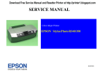
SERVICE MANUAL
Color Inkjet Printer
EPSON Stylus Photo R320
SEIJ04005
Notice
All rights reserved. No part of this manual may be reproduced, stored in a retrieval system, or transmitted in any form or by any means electronic, mechanical,
photocopying, or otherwise, without the prior written permission of SEIKO EPSON CORPORATION.
The contents of this manual are subject to change without notice.
All effort have been made to ensure the accuracy of the contents of this manual. However, should any errors be detected, SEIKO EPSON would greatly
appreciate being informed of them.
The above not withstanding SEIKO EPSON CORPORATION can assume no responsibility for any errors in this manual or the consequences thereof.
EPSON is a registered trademark of SEIKO EPSON CORPORATION.
General Notice:Other product names used herein are for identification purpose only and may be trademarks or registered trademarks of their respective owners.
EPSON disclaims any and all rights in those marks.
Copyright © 2004 SEIKO EPSON CORPORATION.
I&I CS/Quality Management & PL Department
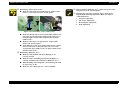
PRECAUTIONS
Precautionary notations throughout the text are categorized relative to 1) Personal injury and 2) damage to equipment.
DANGER
Signals a precaution which, if ignored, could result in serious or fatal personal injury. Great caution should be exercised in performing
procedures preceded by DANGER Headings.
WARNING
Signals a precaution which, if ignored, could result in damage to equipment.
The precautionary measures itemized below should always be observed when performing repair/maintenance procedures.
DANGER
1.
ALWAYS DISCONNECT THE PRODUCT FROM THE POWER SOURCE AND PERIPHERAL DEVICES PERFORMING ANY MAINTENANCE OR REPAIR PROCEDURES.
2.
NO WORK SHOULD BE PERFORMED ON THE UNIT BY PERSONS UNFAMILIAR WITH BASIC SAFETY MEASURES AS DICTATED FOR ALL ELECTRONICS
TECHNICIANS IN THEIR LINE OF WORK.
3.
WHEN PERFORMING TESTING AS DICTATED WITHIN THIS MANUAL, DO NOT CONNECT THE UNIT TO A POWER SOURCE UNTIL INSTRUCTED TO DO SO. WHEN
THE POWER SUPPLY CABLE MUST BE CONNECTED, USE EXTREME CAUTION IN WORKING ON POWER SUPPLY AND OTHER ELECTRONIC COMPONENTS.
4.
WHEN DISASSEMBLING OR ASSEMBLING A PRODUCT, MAKE SURE TO WEAR GLOVES TO AVOID INJURIER FROM METAL PARTS WITH SHARP EDGES.
WARNING
1.
REPAIRS ON EPSON PRODUCT SHOULD BE PERFORMED ONLY BY AN EPSON CERTIFIED REPAIR TECHNICIAN.
2.
MAKE CERTAIN THAT THE SOURCE VOLTAGES IS THE SAME AS THE RATED VOLTAGE, LISTED ON THE SERIAL NUMBER/RATING PLATE. IF THE EPSON PRODUCT
HAS A PRIMARY AC RATING DIFFERENT FROM AVAILABLE POWER SOURCE, DO NOT CONNECT IT TO THE POWER SOURCE.
3.
ALWAYS VERIFY THAT THE EPSON PRODUCT HAS BEEN DISCONNECTED FROM THE POWER SOURCE BEFORE REMOVING OR REPLACING PRINTED CIRCUIT
BOARDS AND/OR INDIVIDUAL CHIPS.
4.
IN ORDER TO PROTECT SENSITIVE MICROPROCESSORS AND CIRCUITRY, USE STATIC DISCHARGE EQUIPMENT, SUCH AS ANTI-STATIC WRIST STRAPS, WHEN
ACCESSING INTERNAL COMPONENTS.
5.
DO NOT REPLACE IMPERFECTLY FUNCTIONING COMPONENTS WITH COMPONENTS WHICH ARE NOT MANUFACTURED BY EPSON. IF SECOND SOURCE IC OR
OTHER COMPONENTS WHICH HAVE NOT BEEN APPROVED ARE USED, THEY COULD CAUSE DAMAGE TO THE EPSON PRODUCT, OR COULD VOID THE
WARRANTY OFFERED BY EPSON.
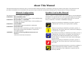
About This Manual
This manual describes basic functions, theory of electrical and mechanical operations, maintenance and repair procedures of the printer. The instructions and
procedures included herein are intended for the experienced repair technicians, and attention should be given to the precautions on the preceding page.
Manual Configuration
This manual consists of six chapters and Appendix.
CHAPTER 1. TROUBLESHOOTING
Describes the step-by-step procedures for the troubleshooting.
CHAPTER 2. DISASSEMBLY / ASSEMBLY
Describes the step-by-step procedures for disassembling and
assembling the product.
CHAPTER 3. ADJUSTMENT
Provides Epson-approved methods for adjustment.
CHAPTER 4. MAINTENANCE
Provides preventive maintenance procedures and the lists of
Epson-approved lubricants and adhesives required for
servicing the product.
APPENDIX Provides the following additional information for
reference:
• Electrical circuit boards schematics
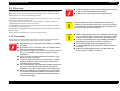
Symbols Used in this Manual
Various symbols are used throughout this manual either to provide additional
information on a specific topic or to warn of possible danger present during a
procedure or an action. Be aware of all symbols when they are used, and
always read NOTE, CAUTION, or WARNING messages.
A D J U S T M E N T
R E Q U IR E D
Indicates an operating or maintenance procedure, practice or
condition that is necessary to keep the product’s quality.
C A U T IO N
Indicates an operating or maintenance procedure, practice, or
condition that, if not strictly observed, could result in damage to,
or destruction of, equipment.
C H E C K
P O IN T
May indicate an operating or maintenance procedure, practice or
condition that is necessary to accomplish a task efficiently. It
may also provide additional information that is related to a
specific subject, or comment on the results achieved through a
previous action.
W A R N IN G
Indicates an operating or maintenance procedure, practice or
condition that, if not strictly observed, could result in injury or
loss of life.
Indicates that a particular task must be carried out according to a
certain standard after disassembly and before re-assembly,
otherwise the quality of the components in question may be
adversely affected.
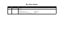
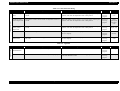
Revision Status
Revision
Issued Date
Description
A
September 3, 2004
First Release
B
September 27, 2004
Revised Contents
[Chapter 2]
• Checkpoint (page 37)
• Page 47, 48, 52, 54, 55, 68, 69
• Adjustment item for PF Timing Belt (page 80)
: Newly added
: Corrected errors
: Deleted
EPSON Stylus Photo R320
Revision B
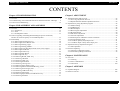
CONTENTS
Chapter 1 TROUBLESHOOTING
Chapter 3 ADJUSTMENT
1.1 Overview .............................................................................................................. 8
3.1 Adjustment Items and Overview ........................................................................ 83
3.1.1 Servicing Adjustment Item List ................................................................. 83
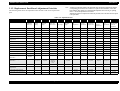
3.1.2 Replacement Part-Based Adjustment Priorities ........................................ 86
1.2 Troubleshooting with LED/LCD Indications and Status Monitor 3 Message ..... 9
1.3 Unit Level Troubleshooting ............................................................................... 14
Chapter 2 DISASSEMBLY AND ASSEMBLY
2.1 Overview ............................................................................................................
2.1.1 Precautions .................................................................................................
2.1.2 Tools ..........................................................................................................
2.1.3 Pre-Shipment Checks .................................................................................
32
32
33
33
2.2 Caution regarding assembling/disassembling the printer mechanism,
and how to ensure the quality of reassembled product ....................................... 35
2.3 Disassembly ........................................................................................................ 37
2.3.1 Removing Paper Support Assy. ................................................................. 38
2.3.2 Removing Preview Monitor Unit .............................................................. 39
2.3.3 Removing Housing, Upper ........................................................................ 40
2.3.4 Removing Housing, Middle ....................................................................... 41
2.3.5 Removing Porous Pad, Paper Guide, Front, Left, Support ........................ 43
2.3.6 Removing Panel Board .............................................................................. 45
2.3.7 Removing Stacker Assy. ............................................................................ 46
2.3.8 Removing Main Board .............................................................................. 47
2.3.9 Removing ASF Assy. ................................................................................ 50
2.3.10 Removing Holder, Shaft Assy. ................................................................ 53
2.3.11 Removing CR Motor ............................................................................... 56
2.3.12 Removing APG Assy. .............................................................................. 57
2.3.13 Removing Print Head .............................................................................. 59
2.3.14 Removing Carriage Unit .......................................................................... 60
2.3.15 Removing Paper Guide, Upper ................................................................ 66
2.3.16 Removing Printer Mechanism/Housing, Lower ...................................... 67
2.3.17 Removing Power Supply Unit ................................................................. 71
2.3.18 Removing CDR Guide Assy. ................................................................... 72
2.3.19 Removing Ink System .............................................................................. 74
2.3.20 Removing Paper Guide, Front/Roller EJ Assy. ....................................... 77
2.3.21 Removing PF Motor ................................................................................ 81
3.2 Adjustment by using adjustment program ..........................................................
3.2.1 Market Setting ...........................................................................................
3.2.2 USB ID Input .............................................................................................
3.2.3 Head ID Input ............................................................................................
3.2.4 Head Angular Adjustment .........................................................................
3.2.5 Bi-d Adjustment ........................................................................................
3.2.6 PW Sensor Adjustment ..............................................................................
3.2.7 First Dot Adjustment .................................................................................
3.2.8 Offset Input for CR Motor Calorific Limitation ........................................
3.2.9 A4 Normal Paper Print ..............................................................................
3.2.10 A4 Photo Quality Inkjet Paper Print ........................................................
3.2.11 A4 Photo Paper/ Glossy Photo Paper print ..............................................
88
88
88
88
89
89
90
90
91
91
91
91
3.3 Adjustment Except Adjustment Program ........................................................... 92
3.3.1 PG Adjustment .......................................................................................... 92
3.4 Firmware Updating ............................................................................................. 95
3.4.1 Firmware Updating Procedure ................................................................... 95
3.4.2 Abnormal Updating Termination .............................................................. 96
Chapter 4 MAINTENANCE
4.1 Overview ............................................................................................................ 98
4.1.1 Cleaning ..................................................................................................... 98
4.1.2 Service Maintenance .................................................................................. 98
4.1.3 Lubrication ............................................................................................... 100
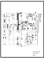
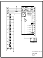
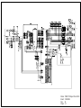
Chapter 5 APPENDIX
5.1 Exploded Diagram ............................................................................................ 108
5.2 Electrical Circuits ............................................................................................. 108
6
CHAPTER
1
TROUBLESHOOTING
EPSON Stylus Photo R320
Revision B
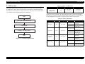
1.1 Overview
Table 1-1. Motor, Coil Resistance
This chapter describes how to identify troubles in two levels: unit level repair and
component level repair. Refer to the flowchart in this chapter to identify the defective
unit and perform component level repair if necessary. This chapter also explains motor
coil resistance, Sensor specification and error indication.
START
Motor
Location
Check Point
Resistance
PF Motor
(Same as ASF/
Pump Motor)
CN9
Pin 1 and 3
Pin 2 and 4
3.0Ω ±10%
(25°C/phase)
Since CR Motor and APG Motor are DC motors, the resistance value among the
electric poles varies. Therefore, the values cannot be used to judge the abnormality.
The only way to judge it is visible status like if the motor rotates or not. Naturally the
accurate judgement is impossible, so replace the motor when it is suspected.
Table 1-2. Sensor check point
Sensor name
UNIT-LEVEL TROUBLESHOOTING
PE Sensor
Location
CN4
Check point
PG Sensor
END
Star Wheel
Sensor
CN5
CN6
TROUBLESHOOTING
Overview
CN6
More than 2.4V
Off :
No paper
Less than 0.4V
On :
Detect paper
More than 2.4V
Off :
Anywhere of PG
Less than 0.4V
On :
In process of
switching PG
Pin 1 and 2
-
On :
ASF mode
-
Off :
CDR mode
-
Off :
No CDR Tray
-
On :
Detect CDR Tray
Pin 1 and 2
Figure 1-1. Troubleshooting Flowchart
CDR Sensor
Switch mode
Pin 1 and 2
UNIT REPAIR
ASSEMBLY AND ADJUSTMENT
Signal level
Pin 3 and 4
8
EPSON Stylus Photo R320
Revision B
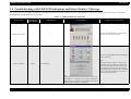
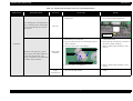
1.2 Troubleshooting with LED/LCD Indications and Status Monitor 3 Message
This section describes the LED/LCD indication, the STM3 message and the error condition when the printer detects an error in each operation such as the power on, the paper
loading/feeding and the ink absorption operation.
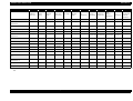
Table 1-3. LED/LCD Indication and STM3
Printer status
Maintenance
LED indication
LCD indication
Communication Error
--
--
STM3 message
Condition for error detection
This error is detected when the printer cannot
communicate with the PC properly.
This error is detected when the ink consumption
reaches about 90%.
Ink Low Condition
Blink
(Note)
When the Ink Low Condition is detected, the
Maintenance LED will blink. The printer will
continue to keep this LED status even if a new
Ink Cartridge is installed in the Ink Cartridge
replacement position. However, this LED status
will be reset (LED off) when "Carriage Unit"
returns to the home position.
(Ink icon blinks)
Note :
Printing operation can be performed until it becomes ink
end condition even after the error message is displayed on
STM3. However, the Head Cleaning operation may not be
performed due to the Ink Low condition.
TROUBLESHOOTING
Troubleshooting with LED/LCD Indications and Status Monitor 3 Message
9
EPSON Stylus Photo R320
Revision B
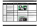
Table 1-3. LED/LCD Indication and STM3
Printer status
Maintenance
LED indication
Ink Out Error
No Ink Cartridge
TROUBLESHOOTING
On
LCD indication
STM3 message
Ink out
Black: T0481
For best results, use genuine EPSON
ink.
Condition for error detection
This error is detected in either of the following
cases.
1. The ink consumption reached 100%.
2. The Ink Cartridge is faulty. (CSIC memory
data error)
(Note)
Even in the Ink Out Error status, a small amount
of ink still remains in the Ink Cartridge to
protect the Print Head from printing without
ink.
Ink cartridges cannot be recognized
Cyan: T0482
For best results, use genuine EPSON
ink.
This error is detected when the Ink Cartridge
has not installed, or not installed properly.
Ink cartridges cannot be recognized
Light Cyan: T0485
For best results, use genuine EPSON
ink.
This error is detected when the printer cannot
read and write the CSIC information of the
installed Ink Cartridge.
Blink
Troubleshooting with LED/LCD Indications and Status Monitor 3 Message
10
EPSON Stylus Photo R320
Revision B
Table 1-3. LED/LCD Indication and STM3
Printer status
Maintenance
LED indication
Paper Out Error
On
Paper Jam Error
(Including CD/DVD)
Maintenance Request
TROUBLESHOOTING
LCD indication
STM3 message
Condition for error detection
Paper load error. Load correctly and
press Maintenance.
This error is detected when the leading edge of
paper cannot be detected with the PE Sensor in
a paper loading.
On
A paper jam has occurred. See your
printer's documentation for
information about clearing the jam.
This error is detected when ;
1. The posterior end of paper cannot be
correctly detected with the PE Sensor in a
paper loading.
2. The rear of CD/DVD cannot be correctly
detected with the Star Wheel/CDR Sensor in
a CD/DVD loading.
On
Service required.
Printer parts are at end of service life.
See printer manual for details.
This error is detected when the value of the
Waste Ink Pad Counter A set in EEPROM
reaches its limit (Variable between 20000 and
46750 points).
Troubleshooting with LED/LCD Indications and Status Monitor 3 Message
11
EPSON Stylus Photo R320
Revision B
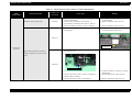
Table 1-3. LED/LCD Indication and STM3
Printer status
Maintenance
LED indication
LCD indication
STM3 message
Condition for error detection
CD/DVD Guide Error
On
Close the CD/DVD guide.
This error is detected when ;
1. Paper is present in "ASF Assy.", and "CDR
Guide Assy." is open while receiving print
data.
2. "CDR Guide Assy." opens while printing.
3. "CDR Guide Assy." is open while receiving
ASF paper feed data.
4. Attempting to replace the ink while "CDR
Guide Assy." is open.
CD/DVD Tray Error
On
The CD/DVD tray load error. Reload
tray and press Maintenance.
This error is detected when "CD/DVD Tray"
cannot be detected when printing CD/DVD.
Memory Card Error
(Non supported
Memory Card)
On
The inserted card cannot be used with
this printer.
No Display
This error is detected when nonstandardized
Memory Card is inserted.
Bluetooth Module Error
On
Bluetooth Photo Print Adapter error.
Disconnect the Adapter from the
printer, then reconnect it.
No Display
This error is detected when there is no response
from Bluetooth Module.
Irregular external device
Blink
The connected device cannot be used.
(The warning is displayed for one
second every 3 seconds.)
No Display
This error is detected when some non supported
device is connected to the port for the external
memory device.
TROUBLESHOOTING
Troubleshooting with LED/LCD Indications and Status Monitor 3 Message
12
EPSON Stylus Photo R320
Revision B
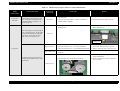
Table 1-3. LED/LCD Indication and STM3
Printer status
Maintenance
LED indication
Fatal error
TROUBLESHOOTING
On
LCD indication
STM3 message
System error. Press and hold both
Power and Stop buttons for 7 seconds.
Troubleshooting with LED/LCD Indications and Status Monitor 3 Message
Condition for error detection
This error is detected when ;
1. "Carriage Unit" cannot move correctly by the
external force in each operation.
2. "PF Motor" cannot rotate correctly while "PF
Motor" operates.
13
EPSON Stylus Photo R320
Revision B
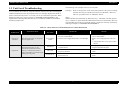
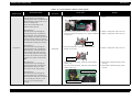
1.3 Unit Level Troubleshooting
The following is the example of how to use the tables.
You can identify the troubles by using the checklist in this section after confirming the
LED/LCD indication on the control panel or the error message displayed on STM3 of
the PC connected to the printer. As a result, you can save the whole repair time. When
finding any faulty parts, refer to Chapter 2 "ASSEMBLY/DISASSEMBLY" and
replace them. Following tables describe the error conditions (LED/LCD and STM3)
and their possible cause.
Example)
When "Carriage Unit" is out of the home position at the power on timing,
the Fatal Error may be caused by the failure of "CR Motor". Moreover,
there are 3 possible causes on "CR Motor" failure.
(Note)
When individual part that makes up "Roller EJ Assy.", "PF Motor" and "Ink System
Assy." is defective, replace the Printer Mechanism with a new one basically. However,
if an individual part needs to be replaced urgently, execute the necessary operation by
referring to Chapter 2 "ASSEMBLY/DISASSEMBLY".
Table 1-4. Check Points for Communication Error to Each Phenomenon
Occurrence Timing
Position of CR
Phenomenon Detail
At power-on
Anywhere
When turning the power on, the printer
does not operate at all.
At operation
When turning the power on, the
initialization is performed correctly.
However, a Communication Error is
displayed on STM3 even transferring the
printing job to the printer.
TROUBLESHOOTING
Faulty Part/
Part Name
Check Point
Remedy
1. Check if "Power Supply Board Cable" is connected to
the CN2 on "Main Board".
2. Check if "Power Supply Board Cable" is not damaged.
1. Connect "Power Supply Board cable" to the
CN2 on "Main Board".
2. Replace "Power Supply Board" with a new
one.
* If the problem still occurs, replace "Main
Board".
Main Board
1. Check if the correct model name is written in EEPROM
on "Main Board".
1. Write proper Market Setting to the EEPROM
using the Adjustment Program.
USB Cable
1. Check if "USB Cable" is connected properly between
the printer and the PC.
1. Connect the printer and the PC with a "USB
Cable".
Printer Driver
1. Check if the Stylus Photo R320 Printer Driver is used
for the printer job.
1. Install the Stylus Photo R320 Printer Driver on
the PC.
Power Supply
Board
Unit Level Troubleshooting
14
EPSON Stylus Photo R320
Revision B
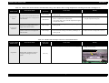
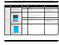
Table 1-5. Check Points for Error Before the Initial Ink Charge, Error Before Ink Cartridge Replacement Cleaning and No Ink Cartridge Error
Occurrence Timing
Position of CR
At power-on
At HP
At power-on
Anywhere
Faulty Part/
Part Name
Phenomenon Detail
The printer does not perform the Initial
Ink Charge and the error is displayed on
LED and STM3.
Check Point
Remedy
Ink Cartridge
1. Check if the Ink Cartridge is normal by installing it in
another printer.
1. Replace the Ink Cartridge with a new one.
Main Board
1. Check if the correct data has been written in the address
5B<H> of EEPROM on "Main Board".
(You cannot check it only with the Adjustment Program
of Stylus Photo R320.)
1. Write proper Market Setting to the EEPROM
using the Adjustment Program.
1. Check if the Ink Cartridge is normal by installing it in
another printer.
1. Replace the Ink Cartridge with a new one.
1. Check if ink still remains in the Ink Cartridge.
2. Check if the Ink Cartridge is normal by installing it in
another printer.
1. Replace the Ink Cartridge with a new one.
2. Replace the Ink Cartridge with a new one.
The printer does not perform the Ink
Replacement Cleaning and the error is
displayed on LED and STM3.
Ink Cartridge
The printer does not perform any print
operation and the error is displayed on
LED and STM3.
Ink Cartridge
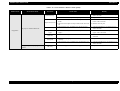
Table 1-6. Check Points for Paper Out Error to Each Phenomenon
Occurrence Timing
Position of CR
Phenomenon Detail
Faulty Part/
Part Name
Check Point
1. Check if "Hopper" works properly while feeding paper.
Remedy
1. Reassemble "ASF Frame" and "Compression
Spring, 2.51" correctly.
Compression Spring, 2.51
At operation
-
"Holder, Shaft, LD Roller" rotates to
feed paper, but "Hopper" does not
operate.
TROUBLESHOOTING
ASF Assy.
Unit Level Troubleshooting
15
EPSON Stylus Photo R320
Revision B
Table 1-6. Check Points for Paper Out Error to Each Phenomenon
Occurrence Timing
Position of CR
Phenomenon Detail
Faulty Part/
Part Name
Check Point
1. Check if "Roller, Retard Assy." operates properly while
feeding paper.
When feeding paper, the leading edge of
paper is detected properly, but the paper
is ejected without being set at the print
start position.
Remedy
1. Reassemble "Extension Spring, 0.45" located
the rear side of "Roller, Retard Assy.".
ASF Assy.
Extension
Spring, 0.45
1. Check if "Extension Spring,0.143" in "Clutch
Mechanism" has not come off.
2. Check if "Clutch" has not come off from the dowel of
"Shaft, LD Roller".
3. Check if "Clutch Tooth" is not damaged.
At operation
-
1. Reassemble "Extension Spring, 0.143" in
"Clutch Mechanism".
2. Reassemble the round portion of "Clutch" on
the dowel of "Shaft, LD Roller".
3. Replace "Holder, Shaft, LD Roller" with a
new one.
Extension Spring, 0.143
"PF Motor" and "Spur Gear, 37.242"
rotate properly, but "Holder, Shaft, LD
Roller" does not feed paper. (The
driving of "PF Motor" is not transmitted
to "Holder, Shaft, LD Roller".)
Holder, Shaft,
LD Roller
Clutch Tooth
Dowel of "Holder, Shaft, LD Roller"
Paper Guide,
Upper
(Only HP side)
TROUBLESHOOTING
4. Check if "Clutch" is not damaged.
4. Replace "Holder, Shaft, LD Roller" with a
new one.
1. Check if "Paper Guide, Upper" (only HP side) has not
come off from "Main Frame".
1. Reassemble "Paper Guide, Upper" to "Main
Frame".
Unit Level Troubleshooting
16
EPSON Stylus Photo R320
Revision B
Table 1-6. Check Points for Paper Out Error to Each Phenomenon
Occurrence Timing
Position of CR
Phenomenon Detail
Faulty Part/
Part Name
Check Point
Remedy
1. Check if "Compression Spring, 2.36" of "Lever, Change"
does not come off.
1. Replace "Ink System" with a new one.
Lever, Change
"PF Motor" and "Spur Gear, 37.242"
rotate properly, but "Holder, Shaft, LD
Roller" does not feed paper. (The drive
of "PF Motor" is not transmitted to
"Holder, Shaft, LD Roller".)
Ink System
At operation
-
Compression Spring, 2.36
"Holder, Shaft, LD Roller" is not set in
the ASF home position and paper is
always fed from "ASF Assy.".
"Holder, Shaft, LD Roller" does not feed
paper during the feeding operation. "PF
Motor" and "Spur Gear, 37.242" also
does not rotate at all.
At operation
-
"Holder, Shaft, LD Roller" rotates
properly, but paper is not fed.
1. Check if the tip of "Lever, Change" is damaged.
1. Replace "Ink System" with a new one.
1. Check if "PC Connector Cable" is connected to CN9 on
"Main Board".
2. Check if the coil resistance of "PF Motor" is
approximately 3.0Ω with a tester. Refer to Table 1-1.
3. Check if "PF Motor Connector Cable" is damaged.
1. Connect "PF Motor Connector Cable" to CN9
on "Main Board".
2. Replace "PF Motor" with a new one.
1. Check if the surface of "LD Roller" is contaminated with
paper dust.
1. Remove the dust by using a soft brush or soft
cloth moistened with alcohol.
Ink System
PF Motor*
3. Replace "PF Motor" with a new one.
* If the problem is not solved, replace "LD
Roller" with a new one.
Holder, Shaft
LD Roller
LD Roller
TROUBLESHOOTING
Unit Level Troubleshooting
17
EPSON Stylus Photo R320
Revision B
Table 1-7. Check Points for Paper Jam Error to Each Phenomenon
Occurrence
Timing
Position of CR
Phenomenon Detail
"PF Motor" does not work at all.
Faulty Part/
Part Name
PF Motor
Check Point
Remedy
1. Check if "PF Motor Connector Cable" is connected to
CN9 on "Main Board".
2. Check if the coil resistance of "PF Motor" is
approximately 3.0Ω with a tester. Refer to Table 1-1.
3. Check if "PF Motor Connector Cable" is damaged.
1. Connect "PF Motor Connector Cable" to CN9
on "Main Board".
2. Replace "PF Motor" with a new one.
1. Check if "Roller, Retard Assy." operates properly while
feeding paper.
1. Reassemble "Extension Spring, 0.45" located
rear side of "Roller, Retard Assy.".
3. Replace "PF Motor" with a new one.
ASF Assy.
Extension
Spring, 0.45
At power-on
Anywhere
1. Check if "Torsion Spring, 0.22" is not unfastened from
"PE Sensor Lever".
Paper feeding operation is performed
normally, but paper is not sent into the
printer.
1. Reassemble "Torsion Spring, 0.22"
PE Sensor
Torsion Spring, 0.22
2. Check if "PE Sensor Cable" is not unfastened.
3. Check if "PE Sensor Cable" is correctly mounted on
"Holder, Shaft, LD Roller".
4. Check if "PE Sensor Cable" is not damaged.
TROUBLESHOOTING
Unit Level Troubleshooting
2. Connect "PE Sensor" Connector to CN4 on
"Main Board".
3. Remount "PE Sensor Cable" correctly.
4. Replace "PE Sensor" with a new one.
18
EPSON Stylus Photo R320
Revision B
Table 1-7. Check Points for Paper Jam Error to Each Phenomenon
Occurrence
Timing
Position of CR
Phenomenon Detail
At operation
Out of HP
"Carriage Unit" moves to the home
position properly when turning on the
power. Then paper feeding operation is
performed normally, but paper is not
sent into the printer.
When feeding paper, the leading edge of
paper is detected properly, but the paper
is ejected without being set at the print
start position. At this time, the next
paper is fed to "PE Sensor Lever".
Faulty Part/
Part Name
Check Point
PE Sensor*
Remedy
1. Check if "Torsion Spring, 0.22" for "PE Sensor Lever" is
not unfastened.
2. Check if "PE Sensor Cable" is correctly mounted on
"Holder, Shaft, LD Roller".
1. Reassemble "Torsion Spring, 0.22".
1. Check if "Roller, Retard Assy." operates properly while
feeding paper.
1. Reassemble "Extension Spring, 0.45" back of
"Roller, Retard Assy."
2. Remount "PE Sensor Cable" correctly.
ASF Assy.
Extension
Spring, 0.45
Frame EJ Assy.**
1. Check if "Star Wheels" have not come off.
2. Check if "Frame EJ Assy." is correctly assembled.
3. Check if "Frame EJ Assy." is not transformed downward.
1. Reassemble "Star Wheels" correctly.
2. Reassemble "Frame EJ Assy." correctly.
3. Replace "Frame EJ Assy." with a new one.
Paper Guide, Front
1. Check if "Porous pad" of "Paper Guide, Front" has not
come off.
1. Remount "Porous pad" correctly.
1. Check if "Roller EJ Assy." is correctly assembled.
1. Reassemble "Roller EJ Assy." correctly onto
"Printer Mechanism".
2. Reattach "Spur Gear, 41.48" to "Roller EJ
Assy." correctly.
At operation
-
The leading edge of paper does not go
through between "Roller EJ Assy." and
"Star Wheels".
2. Check if "Spur Gear, 41.48" has not come off.
Roller EJ Assy.
Spur Gear, 41.48
TROUBLESHOOTING
Unit Level Troubleshooting
19
EPSON Stylus Photo R320
Revision B
Table 1-7. Check Points for Paper Jam Error to Each Phenomenon
Occurrence
Timing
Position of CR
Phenomenon Detail
Faulty Part/
Part Name
Check Point
1. Check if "Paper Guide, Upper" has not come off from
"Main Frame".
Remedy
1. Reattach "Paper Guide, Upper" to "Main
Frame".
Paper Guide, Upper
At operation
-
The leading edge of paper is not sent to
"PF Roller".
Paper Guide,
Upper
* "Carriage Unit" can move to the home position even if "Extension Spring, 0.22" has come off or "PE Sensor" is not set in the correct position. However, in the next operation, a Paper Jam Error
will be detected since "PE Sensor Lever" will maintain the High signal status.
** There some cases where the jammed paper may damage "Print Head" by contacting the surface of "Print Head nozzle" when a Paper Jam Error occurs in each operation.
TROUBLESHOOTING
Unit Level Troubleshooting
20
EPSON Stylus Photo R320
Revision B
Table 1-8. Check Points for CD/DVD Guide Error to Each Phenomenon
Occurrence Timing
Position of CR
Phenomenon Detail
Faulty Part/
Part Name
Check Point
Remedy
1. Check if the contact point of "Housing, Middle" with
"Star Wheel/CDR Sensor" is cracked.
Contact
point
Housing, Middle
At power-on
At HP
1. Check if "Star Wheel/CDR Sensor" is connected to CN6
on "Main Board".
An error occurs even if "CDR Guide
Assy." is closed when turning on the
power.
1. Replace "Housing, Middle" with a new one.
1. Connect "Star Wheel/CDR Sensor" to CN6
on "Main Board".
Star Wheel/CDR Sensor
Star Wheel/
CDR Sensor
2. Check if "Star Wheel/CDR Sensor" is damaged.
3. Check if "Star Wheel/CDR Sensor" cable is cut off.
Main Board
TROUBLESHOOTING
1. Check if any device on "Main Board" is damaged.
Unit Level Troubleshooting
2. Replace "Star Wheel/CDR Sensor" with a
new one.
3. Replace "Star Wheel/CDR Sensor" with a
new one.
1. Replace "Main Board" with a new one.
21
EPSON Stylus Photo R320
Revision B
Table 1-9. Check Points for CD/DVD Tray Error to Each Phenomenon
Occurrence Timing
Position of CR
Phenomenon Detail
Faulty Part/
Part Name
Check Point
1. Check if the contact point of "CDR Tray" with "CDR
Tray Sensor" is cracked.
Remedy
1. Replace "CDR Tray" with a new one.
CDR Tray
Contact point
When printing
CDR/DVDR
-
1. Check if "CDR Tray Sensor" is connected to CN6 on
"Main Board".
An error occurs even though "CDR
Tray" is set when printing CDR/DVDR.
1. Connect "CDR Tray Sensor" to CN6 on
"Main Board".
CDR Tray Sensor
CDR Tray Sensor
Main Board
TROUBLESHOOTING
2. Check if "CDR Tray Sensor" is damaged.
2. Replace "CDR Tray Sensor" with a new one.
3. Check if "CDR Tray Sensor Connector Cable" is cut off.
3. Replace "CDR Tray Sensor" with a new one.
1. Check if any device on "Main Board" is damaged.
1. Replace "Main Board" with a new one.
Unit Level Troubleshooting
22
EPSON Stylus Photo R320
Revision B
Table 1-10. Check points for Memory Card Error to Each Phenomenon
Occurrence Timing
Position of CR
Phenomenon Detail
Faulty Part/
Part Name
Check Point
1. Check if the Memory Card is compliant.
Memory Card
When inserting
Memory Card
-
2. Check if the Memory Card is damaged.
The Memory Card is not detected, and
an error is displayed on LED and STM3.
Main Board
TROUBLESHOOTING
1. Check if there is any damage on the slot pin of the loading
slot for Memory Cards.
2. Check if any elements on "Main Board" is damaged.
Unit Level Troubleshooting
Remedy
1. Replace the Memory Card with a compliant
one.
2. Replace the Memory Card with a new one.
1. Replace "Main Board" with a new one.
2. Replace "Main Board" with a new one.
23
EPSON Stylus Photo R320
Revision B
Table 1-11. Check Points for Fatal Error to Each Phenomenon
Occurrence Timing
Position of CR
Phenomenon Detail
"CR Motor" does not work at all when
turning on the power.
Faulty Part/
Part Name
Check Point
Remedy
CR Motor
1. Check if "CR Motor Connector Cable" is connected to
CN8 on "Main Board".
2. Check if "CR Motor Connector Cable" is damaged.
1. Connect "CR Motor Connector Cable" to
CN8 on "Main Board".
2. Replace "CR Motor" with a new one.
PF Motor
1. Check if "PF Motor Connector Cable" is connected to
CN9 on "Main Board".
2. Check if the resistance of "PF Motor" is approximately
3.0Ω using a tester. Refer to Table 1-1.
3. Check if "PF Motor Connector Cable" is damaged.
1. Connect "PF Motor Connector Cable" to CN9
on "Main Board".
2. Replace "PF Motor" with a new one.
1. Check if "Compression Spring, 2.36" of "Lever, Change"
has not come off.
1. Replace "Ink System" with a new one.
"Carriage Unit" strikes on "Lever,
Change" because the lever is leaning
forward when turning on the power.
3. Replace "PF Motor" with a new one.
Lever, Change
Ink System
At power-on
Out of HP
Compression Spring, 2.36
1. Check if "Paper Guide, Upper" has come off from "Main
Frame".
1. Reassemble "Paper Guide, Upper" to "Main
Frame".
Paper Guide, Upper
At power-on
Anywhere
"Carriage Unit" strikes on "Paper Guide,
Upper" which has come off from "Main
Frame" when turning on the power.
Paper Guide,
Upper
"Carriage Unit" strikes on the right side
of "Main Frame" when turning on the
power.
CR Scale
TROUBLESHOOTING
1. Check if "CR Scale" has come off, or it properly passes
through the slit of "CR Encoder Sensor Board".
Unit Level Troubleshooting
1. Reassemble "CR Scale" correctly.
* If the problem is not solved, replace
"Main Board" with a new one.
24
EPSON Stylus Photo R320
Revision B
Table 1-12. Check Points When More Than One Paper is Fed Constantly Without LED/STM3's Error Notifications
Occurrence Timing
Position of CR
Phenomenon Detail
Faulty Part/
Part Name
Check Point
1. Check if "Roller, Retard Assy." works correctly while
feeding paper.
At operation
-
The printer always feeds more than one
sheet of paper at a time without LED/
STM3's error notifications.
Remedy
1. Reassemble "Extension Spring, 0.45" on the
back of "Roller, Retard Assy."
ASF Assy.
Extension Spring,
0.45
Table 1-13. Check Points for Abnormal Sound
Occurrence Timing
Position of CR
Phenomenon Detail
Makes abnormal sound in spite of the
normal print operation at the first power
on or some other time.
Any time
Anywhere
Faulty Part/
Part Name
Check Point
Carriage Unit
Ink System
The bottom of "Carriage Unit" touches
the surface of "Front Frame".
Frame EJ Assy.
"Carriage Unit" strikes on "Paper Guide,
Upper" while "Carriage Unit" is
working.
Paper Guide,
Upper
TROUBLESHOOTING
Remedy
1. Check if there is enough grease on "CR Guide Shaft".
1. Wipe the remaining grease off on "CR Guide
Shaft" and then lubricate it.
1. Check if "Lever, Change" moves smoothly.
1. Replace "Ink System" with a new one.
1. Check if "Frame EJ Assy." is not warping upward.
1. Replace "Frame EJ Assy." with a new one.
1. Check if "Paper Guide, Upper" has come off from "Main
Frame".
1. Reassemble "Paper Guide, Upper" to "Main
Frame".
Unit Level Troubleshooting
25
EPSON Stylus Photo R320
Revision B
Table 1-14. Check Points for Defective Print Quality
Occurrence Timing
Position of CR
Phenomenon Detail
Faulty Part/
Part Name
1. Check if there is any foreign matter on the sealing rubber
on "Cap Unit".
[Phenomenon 1]
When the printer is performing the
Cleaning task, the ink is not drained into
"Waste Ink Pad" in spite of the correct
function of "Pump Unit".
The ink from "Print Head" is not
absorbed in the Cap at all.
At operation
-
[Phenomenon 4]
When the printer is performing the
Cleaning task, the ink is drained into
"Waste Ink Pad". However, some
missing dots occurs while printing.
[Phenomenon 5]
When the printer is performing the
Cleaning task, the ink is drained into
"Waste Ink Pad". However, missing dot
occurs and the place where it occurs
varies in every movement of the
Cleaning.
TROUBLESHOOTING
Remedy
1. Remove the foreign matter from the sealing
rubber.
Sealing rubber
[Phenomenon 2]
When the printer is performing the
Cleaning task, the ink is drained into
"Waste Ink Pad". (This indicates that
both of "Pump Unit" and "Cap Unit" are
working correctly.) However, missing
dots is not solved at certain nozzles even
performing the Cleaning several times.
[Phenomenon 3]
When the printer is performing the
Cleaning task, the ink is drained into
"Waste Ink Pad". (This indicates that
both of "Pump Unit" and "Cap Unit"
work correctly.) However, the wiping
function is not executed correctly and
irregular colors appear on the printed
sheet.
Check Point
2. Check if the sealing rubber on "Cap Unit" is damaged.
3. Check if "Compression Spring, 2.53" is properly attached
in "Cap Unit".
2. Replace "Ink System" with a new one.
3. Replace "Ink System" with a new one.
Compression
Spring, 2.53
Ink System
4. Check if "Pump Tube" is properly connected to the
bottom of "Cap Unit".
4. Replace "Ink System" with a new one.
Contact point of
Pump Tube
5. Check if "Extension Spring, 0.788" has come off from
"Slider Cap".
6. Check if "Extension Spring, 0.441" has come off from
"Slider Lock Lever".
5. Reassemble "Extension Spring, 0.788"
correctly.
6. Reassemble "Extension Spring, 0.441"
correctly.
Extension Spring, 0.441
Extension Spring, 0.788
Unit Level Troubleshooting
26
EPSON Stylus Photo R320
Revision B
Table 1-14. Check Points for Defective Print Quality
Occurrence Timing
Position of CR
Phenomenon Detail
[Phenomenon 6]
When the Cleaning is performed, the ink
is drained into "Waste Ink Pad".
However, missing dots and
misalignment occur at all nozzles.
They are not solved by executing the
Cleaning several times.
Faulty Part/
Part Name
Remedy
Ink System
7. Check if "Slider Lock Lever" is damaged.
7. Replace "Ink System" with a new one.
Ink Cartridge
1. Check if ink still remains in Ink Cartridge
1. Replace the Ink Cartridge with a new one.
1. Check if there is any foreign matter on the nozzle surface
of "Print Head".
1. Perform the wiping operation. Replace
"Wiper" when "Wiper" is deformed or
contaminated awfully.
2. Securely connect "Head FFC" to "Main
Board" or the board on "Print Head".
3. Replace "Head FFC" with a new one.
4. Perform Head Cleaning and check the Nozzle
Check Pattern.
* If the problem is not solved, replace "Print
Head" with a new one.
Print Head
* If the problem is not solved,
replace "Main Board" with a new
one.
At operation
-
Check Point
2. Check if "Head FFC" is connected to CN7 and CN8 on
"Main Board", or to the board on "Print Head".
3. Check if "Head FFC" is damaged.
4. Check if each segment prints correctly with the Nozzle
Check Pattern.
1. Check if there is foreign matter on the surface of "CR
Guide Shaft".
2. Check if there is damage on the surface of "CR Guide
Shaft".
3. Check if there is enough grease on the surface of "CR
Guide Shaft".
Striped pattern appears in a direction
perpendicular to "Carriage Unit"
movement.
Direction of
CR movement
Carriage Unit
4. Check if "CR Guide Shaft" is properly connected to
"Main Frame" with the fixing spring of "CR Guide
Shaft".
1. Remove the foreign matter on "CR Guide
Shaft".
2. Replace "CR Guide Shaft" with a new one.
3. Wipe the surface of "CR Guide Shaft" with a
dry soft cloth, and then apply G-63 to it.
Refer to Section 4.1.3.
4. Reassemble "CR Guide Shaft" correctly.
(Note)
If the problem is not solved, replace "CR
Motor" with a new one.
TROUBLESHOOTING
Unit Level Troubleshooting
27
EPSON Stylus Photo R320
Revision B
Table 1-14. Check Points for Defective Print Quality
Occurrence Timing
Position of CR
Phenomenon Detail
Faulty Part/
Part Name
Check Point
Frame EJ Assy.
Striped pattern appears in a direction
perpendicular to "Carriage Unit"
movement.
Striped pattern appears in a direction
horizontally to "Carriage Unit"
movement.
Print Head
PF Roller
Direction of
CR movement
At operation
-
(Note)
If the problem is not solved, replace "PF
Motor" with a new one.
1. Check if the surface of "Frame EJ Assy." is precisely
horizontal.
1. Replace "Frame EJ Assy." with a new one.
1. Check if "Print Head" prints correctly with the Nozzle
Check Pattern.
1. Perform the Head Cleaning, then check the
Nozzle Check Pattern.
* If the problem is not solved, replace "Print
Head" with a new one.
1. Check if there is any foreign matter on the surface of "PF
Roller".
2. Check if "PF Roller" is damaged.
1. Clean the surface of "PF Roller".
3. Check if "Spur Gear, 37.242" is damaged or broken.
Printer Driver and
Special Paper
2. Replace "Printer Mechanism" with a new
one.
3. Replace "Printer Mechanism" with a new
one.
1. Check if appropriate paper is used in accordance with the
Printer Driver settings.
1. Use the appropriate type of paper in
accordance with the Printer Driver.
1. Check if "Print Head" prints correctly with the Nozzle
Check Pattern.
1. Perform the Head Cleaning, then check the
Nozzle Check Pattern.
* If the problem is not solved, replace "Print
Head" with a new one.
1. Check if "Porous pad" in front of "Paper Guide, Front"
has not come off.
1. Reattach "Porous pad".
Print Head
Irregular lines appear in a direction
horizontally to "Carriage Unit"
movement.
Remedy
Paper Guide, Front
These lines appear when the print paths
overlap each other.
TROUBLESHOOTING
Unit Level Troubleshooting
28
EPSON Stylus Photo R320
Revision B
Table 1-14. Check Points for Defective Print Quality
Occurrence Timing
Position of CR
Phenomenon Detail
Traces of "Star Wheels" appear in a
direction perpendicular to "Carriage
Unit" movement.
Faulty Part/
Part Name
Check Point
Frame EJ Assy.
Remedy
1. Check if "Star Wheels" have come off.
2. Check if the surface of "Frame EJ Assy." is mounted
horizontally.
1. Reassemble "Star Wheels" correctly.
2. Replace "Frame EJ Assy." with a new one.
1. Check if "Roller EJ Assy." has come off from "Printer
Mechanism".
1. Reassemble "Roller EJ Assy." correctly.
1. Check if any paper dust has adhered to the surface of "LD
Roller".
1. Remove the dust by using a soft brush or soft
cloth moistened with alcohol.
* If the problem is not solved, replace
"Holder, Shaft, LD Roller" with a new
one.
Roller EJ Assy.
At operation
Normal printing task is performed;
however, the top margin is less than
usual.
Holder, Shaft,
LD Roller
LD Roller
The print is light and thin.
TROUBLESHOOTING
Printer Driver and
Special Paper
1. Check if appropriate paper is used in accordance with the
Printer Driver settings.
1. Use the appropriate type of paper in
accordance with the Printer Driver settings.
Print Head
1. Check if the correct Head ID has been input in EEPROM
by using the Adjustment Program.
1. Input 15-digit ID code of the Head ID in
EEPROM by using the Adjustment Program
Unit Level Troubleshooting
29
EPSON Stylus Photo R320
Revision B
Table 1-14. Check Points for Defective Print Quality
Occurrence Timing
Position of CR
Phenomenon Detail
Faulty Part/
Part Name
Check Point
1. Check if there is any ink adhesion on "Frame EJ Assy.".
1. Clean the ink adhesion on "Frame EJ Assy."
with a soft cloth.
1. Check if "Frame EJ Assy." has warped upward.
1. Replace "Frame EJ Assy." with a new one.
Frame EJ Assy.
1. Check if there is any ink adhesion on "Paper Guide,
Front".
Paper Guide, Front
2. Check if "Porous pad" of "Paper Guide, Front" has come
off.
1. Clean the ink adhesion on "Roller EJ Assy."
with a soft cloth.
1. Check if there is any ink adhesion on "Paper Guide,
Upper".
1. Clean the ink adhesion on "Paper Guide,
Upper" with a soft cloth.
1. Check if there is any ink adhesion on "PF Roller".
1. Clean the ink adhesion on "PF Roller" with a
soft cloth.
Ink System
1. Check if the wiping operation has been performed
correctly.
1. Replace "Ink System" with a new one.
Print Head
1. Check if there is any ink adhesion on "Print Head Cover". 1. Clean the ink adhesion on "Print Head Cover"
with a soft cloth.
The paper is stained with the ink.
Paper Guide,
Upper
PF Roller
The upper edge of the paper gets
creased.
TROUBLESHOOTING
1. Clean the ink adhesion on "Paper Guide,
Front" with a soft cloth.
2. Reattach "Porous pad".
1. Check if there is any ink adhesion on "Roller EJ Assy.".
Roller EJ Assy.
At operation
-
Remedy
ASF Assy.
1. Check if "Hopper Pad" is stuck to "Hopper" correctly.
Unit Level Troubleshooting
1. Replace "ASF Assy." with a new one.
30
CHAPTER
2
DISASSEMBLY AND ASSEMBLY
EPSON Stylus Photo R320
Revision B
2.1 Overview
W A R N IN G
This section describes procedures for disassembling the main components of Stylus
Photo R320. Unless otherwise specified, disassembled units or components can be
reassembled by reversing the disassembly procedure.
"WARNING" indicates procedures which may result in damage, injury or involving
human lives if you don't take extra care.
"CAUTION" indicates precautions for any disassembly or assembly procedures.
"CHECK POINT" indicates points to be checked.
"REASSEMBLY" indicates reassembling procedures which are different from the
reverse order of the disassembling.
"ADJUSTMENT REQUIRED" indicates required adjustments after the assembly and
the disassembly.
C A U T IO N
Read precautions described in the next section before starting.
C A U T IO N
2.1.1 Precautions
Before starting the disassembling/reassembling work of this product, the following
"WARNING" and "CAUTION" should always be observed carefully.
W A R N IN G
the printer.
If you need to work on the printer with power applied, strictly
follow the instructions in this manual.
Wear protective goggles to protect your eyes from ink. If ink gets
in your eye, flush the eye with fresh water and see a doctor
immediately.
Always wear gloves for disassembly and reassembly to avoid
injury from sharp metal edges.
To protect sensitive microprocessors and circuitry, use static
discharge equipment, such as anti-static wrist straps, when
accessing internal components.
Never touch the ink or wasted ink with bare hands. If ink comes
into contact with your skin, wash it off with soap and water
immediately. If you have a skin irritation, consult a physician.
When reassembling the waste ink pads and tray, always make
sure that the waste ink tube is fitted correctly in the specified
place. Fitting the ink tube in other than the specified position
could cause ink leakage.
DISASSEMBLY AND ASSEMBLY
et que le cordon d’alimentation soit debranche.
Veillez a jeter les piles usagees selon le reglement local.
Risque d’explosion si la pile est remplacée incorrectment. Ne
remplacer que par une pile du même type ou d’un type équivalent
recommandé par le fabricant. Eliminer les piles déchargées selon
les lois et les règles de sécurité en vigueur.
When transporting the printer after installing the ink cartridge,
Disconnect the power cable before disassembling or assembling
Avant de commencer, assure vous que l’imprimante soit eteinte
Overview
be sure to pack the printer without removing the ink cartridge
and secure the cartridge to the main body with adhesive tape.
Use only recommended tools for disassembling, assembling or
adjusting the printer. (Refer to Table 2-1 "Tool List".)
Observe the specified torque when tightening screws.
Use the specified lubricants and adhesives. (Refer to Chapter 4
for details.)
Make the specified adjustments when you disassemble the
printer. (Refer to Chapter 3 for details.)
32
EPSON Stylus Photo R320
Revision B
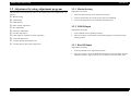
2.1.2 Tools
2.1.3 Pre-Shipment Checks
Use only specified tools to avoid damaging the printer.
When returning this product to the user after servicing, check that the work is complete
using the following table.
Table 2-1. Tools
Tool Name
Supplier
Code
Phillips Screw Driver (No. 0)
EPSON
1080531
Phillips Screw Driver (No. 1)
EPSON
1080530
Phillips Screw Driver (No. 2)
EPSON
1080532
Tweezers
EPSON
1080561
Acetate Tape
EPSON
1003963
Table 2-2. Service Completion Pre-Shipment Check List
Classification
Item
Check Point
Self-test
Is the operation normal?
On-line Test
Is the printing successful?
Print Head
Is ink discharged normally from
all the nozzles?
Does it move smoothly?
Is there any abnormal noise
during its operation?
Carriage
Mechanism
Main Unit
Is there any dirt or foreign
objects on the CR Guide Shaft?
Is the CR Motor at the correct
temperature?
(Not too heated?)
Paper Feeding
Mechanism
•
•
•
•
•
Is paper fed smoothly?
No paper jamming?
No paper skew?
No multiple feeding?
No abnormal noise?
Is the PF Motor at correct
temperature?
Is the paper path free of any
obstructions?
Adjustment
DISASSEMBLY AND ASSEMBLY
Overview
Specified
Adjustment
Are all the adjustment done
correctly?
Status
Checked
Not necessary
Checked
Not necessary
Checked
Not necessary
Checked
Not necessary
Checked
Not necessary
Checked
Not necessary
Checked
Not necessary
Checked
Not necessary
Checked
Not necessary
Checked
Not necessary
Checked
Not necessary
33
EPSON Stylus Photo R320
Revision B
Table 2-2. Service Completion Pre-Shipment Check List
Classification
Lubrication
Function
Item
Specified
Lubrication
Are all the lubrication made at
the specified points?
Is the amount of lubrication
correct?
ROM Version
Is it the latest version?
Version:
Ink Cartridge
Are the ink cartridges installed
correctly?
Protective
Materials
Have all relevant protective
materials been attached to the
printer?
Attachments,
Accessories
Have all of the accessories been
included in the package?
Packing
Others
Check Point
DISASSEMBLY AND ASSEMBLY
Status
Checked
Not necessary
Checked
Not necessary
Checked
Not necessary
Checked
Not necessary
Checked
Not necessary
Checked
Not necessary
Overview
34
EPSON Stylus Photo R320
Revision B
2.2 Caution regarding assembling/disassembling
the printer mechanism, and how to ensure the
quality of reassembled product
For the existing Low End models, it is basically forbidden to remove "Housing,
Lower" from "Printer Mechanism". This is because the strength of "Frame, Main" is
not strong enough, therefore, "Frame, Main" may be transformed when removing/
reinstalling it from/to "Housing, Lower".
For that reason, when replacing "Ink System" or "PF Motor", it is recommended to
replace not only "Housing, Lower" but also "Printer Mechanism".
Management of the reference position for installation
[Reason]
Accurate installation for each component of "Printer Mechanism" is on a basis
of "Housing, Lower".
[Support for Service]
Check if there is no gap between "Frame, Main" and "Housing, Lower".
[Reference]
In order to ensure the accuracy for installation, it is necessary to manage the
reference position for installation in X, Y and Z direction.
[X-axis]
For this printer, "Housing, Lower" needs to be removed from "Printer Mechanism"
when replacing "Waste ink Pads" or "Ink System".
Therefore, this chapter specifies the disassembly/assembly of "Printer Mechanism"
which "Housing, Lower" has been taken out in order to secure the quality of the
repaired items.
• Check if "Frame, Main" is correctly set to the groove of "Housing,
Lower".
• Check that there is no gap between "Frame, Main" and "Housing,
Lower".
[Y-axis]
Caution for disassembly/assembly of Printer Mechanism
1.
"Printer Mechanism" with "Housing, Lower"
• Do not hold "Guide Plate, CR" ⇒ Transforming of "Frame, Main" and
"Guide Plate, CR" may give some bad influence to PG or printing.
• Do not touch "CR Guide Shaft" and the surface of the head nozzle.
2.
"Printer Mechanism" without "Housing, Lower"
• Manage the standard values for installation. (See below)
• First, remove "Support Plate, Frame, Main". Then, remove "Roller PF
Assy.", "Roller EJ Assy." and "Paper Guide, Front".
• Make sure to manage "Waste Ink Tube".
• Routing of "Star Wheel/CDR Sensor" connector cable.
• Assemble "Cam, CR, Left" while gearing with the APG gear.
• Check if the slot of "Frame, Main" is correctly attached to the projection
of "Housing, Lower".
[Z-axis]
• Check that there is no gap between "Frame, Main" and "Housing,
Lower".
• Check if correctly secured with the hooks (2 on the left, 1 on the right, 1
on the right front) of "Printer Mechanism".
Management of the perpendicular accuracy of "Guide Plate, CR" (The
standards of the guide rail's perpendicular direction is on the basis of the
hooks of "Carriage Unit" and "Print Head".)
[Reason]
Deformation of "Guide Plate, CR" may cause the defective print/operation.
[Support for Service]
Specify the correct raising position for "Main Frame" so that it will not be
deformed.
DISASSEMBLY AND ASSEMBLY
Caution regarding assembling/disassembling the printer mechanism, and how to ensure the quality of reassembled product 35
EPSON Stylus Photo R320
Revision B
How to install "ASF Assy.", "Main Board" and "Paper Guide, Upper"
[Reason]
When installing these three components, too much force can be given to
"Frame, Main", therefore, it may be deformed and cause the defective print/
operation.
[Support for Service]
Hold the opposite side of the components securely, when installing them.
3.
CDR Guide Assy.
Management of the level accuracy of "CDR Guide Assy."
[Reason]
Deformation of "CDR Guide Assy." may cause the defective print.
[Support for Service]
Disassemble/assemble carefully "CDR Guide Assy.".
How to secure the quality for reassembled products
It can be judged that the quality for the reassembled products is guaranteed if the
printing test with the Adjustment program is successful.
DISASSEMBLY AND ASSEMBLY
Caution regarding assembling/disassembling the printer mechanism, and how to ensure the quality of reassembled product 36
EPSON Stylus Photo R320
Revision B
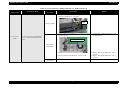
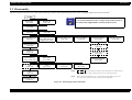
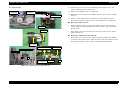
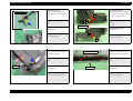
2.3 Disassembly
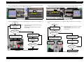
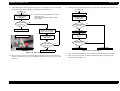
The following flowchart shows the order of disassembling procedure. When disassembling any unit, refer to the page number shown in the flowchart.
START
Removing Paper
Support Assy.
(2.3.1 P.38)
Removing Preview
Monitor Unit
(2.3.2 P.39)
C H E C K
P O IN T
Since we used a mass production trial model for EHC destination
to create this manual, the color or shape of the product shown in
the manual may slightly differs from the product on sale.
Removing Housing, Upper
(2.3.3 P.40)
Removing Housing, Middle
(2.3.4 P.41)
Removing Panel Board
(2.3.6 P.45)
Removing Main Board
(2.3.8 P.47)
Removing Porous Pad,
Paper Guide, Front, Left,
Support (2.3.5 P.43)
Removing Stacker Assy.
(2.3.7 P.46)
Removing CR Motor
(2.3.11 P.56)
Removing ASF Assy.
(2.3.9 P.50)
Removing APG Assy.
(2.3.12 P.57)
Removing Printer
Mechanism/Housing,
Lower (2.3.16 P.67)
Removing Paper
Guide, Upper
(2.3.15 P.66)
Removing Carriage
Unit
(2.3.14 P.60)
Removing Power Supply
Unit
(2.3.17 P.71)
Removing Paper Guide,
Front/Roller EJ Assy.
(2.3.20 P.77)
Removing APG Assy.
(2.3.12 P.57)
Removing Main Board
(2.3.8 P.47)
Removing Holder,
Shaft Assy.
(2.3.10 P.53)
Removing CDR Guide
Assy.
(2.3.18 P.72)
Removing Print Head
(2.3.13 P.59)
Removing Carriage Unit
(2.3.14 P.60)
Removing PF Motor
(2.3.21 P.81)
Removing Ink System
(2.3.19 P.74)
NOTE:
indicates that the procedure in the broken-line box is NOT the shortest
removing procedure, but the passing point for the next removing procedure.
NOTE:
When removing ’CDR Guide Assy.’ or ’Paper Guide, Front/ Roller EJ Assy.’, We
have to remove Carriage Unit before removing Printer Mechanism.
Figure 2-1. Removing Procedure Flowchart
DISASSEMBLY AND ASSEMBLY
Disassembly
37
EPSON Stylus Photo R320
Revision B
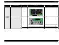
Parts/Units which should be removed before removing "Paper Support Unit"
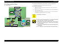
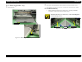
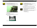
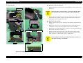
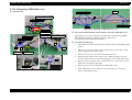
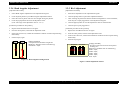
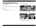
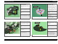
2.3.1 Removing Paper Support Assy.
None
External View
Procedure for Removing
1.
Paper Support Assy.
Release the dowels (x2) which secure "Paper Support Assy.". Then remove
"Paper Support Assy." from "ASF Assy.".
ASF Assy.
Dowels
Figure 2-2. Removing "Paper Support Assy."
DISASSEMBLY AND ASSEMBLY
Disassembly
38
EPSON Stylus Photo R320
Revision B
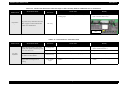
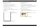
Parts/Units which should be removed before removing "Preview Monitor
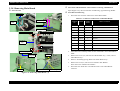
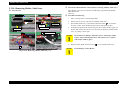
2.3.2 Removing Preview Monitor Unit
Unit"
External View
None
Procedure for Removing
C.B.P 3x8 (2-4kgf•cm)
Preview Monitor Unit
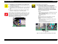
1.
Raise the "Preview Monitor Unit".
2.
Remove the screw(x1) which secure "Preview Monitor Unit".
3.
Release the hook(x2) which secure "Preview Monitor Unit".
Then lift the "Preview Monitor Unit" upward.
4.
Remove the "Monitor FFC" from the "Preview Monitor Board" connector.
Then remove "Preview Monitor Unit".
Hooks
Connector
Monitor FFC
Preview Monitor Board
Figure 2-3. Removing "Preview Monitor Unit"
DISASSEMBLY AND ASSEMBLY
Disassembly
39
EPSON Stylus Photo R320
Revision B
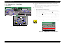
Parts/Units which should be removed before removing "Housing, Upper"
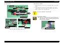
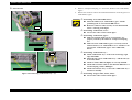
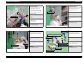
2.3.3 Removing Housing, Upper
Paper Support Assy./Preview Monitor Unit
External View
Procedure for Removing
Housing, Upper
Printer Cover
C.B.P 3x8 (4-6kgf•cm)
1
4
3
2
Dowels
Carriage Unit
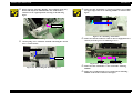
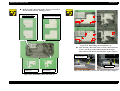
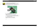
1.
Release the dowels(x2) of "Printer Cover". Then remove the "Printer Cover"
from "Housing Upper".
2.
Remove the screws (x4) which secure "Housing, Upper".
3.
Release "Carriage Lock" with the tweezers or alike and then move "Carriage
Unit" toward the centre.
4.
Release the hooks (x4) which secure "Housing, Upper" and then lift up
"Housing, Upper".
5.
Detach "Panel FFC" from the connector of "Panel Board" and then remove
"Housing, Upper".
Tighten the screws in the order as shown in the figure.
Make sure to put the dowels (x2) of "Housing, Upper" into the
attaching holes (x2) on "Printer Cover".
Dowels
Carriage Lock
Hooks
Hooks
Printer Cover
Connector
Panel FFC
Attaching Holes
Figure 2-5. Reinstalling "Printer Cover"
Figure 2-4. Removing "Housing, Upper"
DISASSEMBLY AND ASSEMBLY
Disassembly
40
EPSON Stylus Photo R320
Revision B
Procedure for Removing
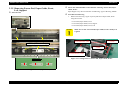
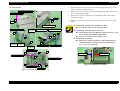
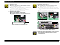
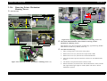
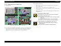
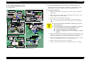
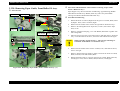
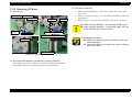
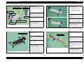
2.3.4 Removing Housing, Middle
External View
Fixed spring, Core
Housing, Middle
Ferrite Core
Two-sided
Tape
Housing, Lower
Hook
2.
Take off the two-sided tape which fixing the "Panel FFC" from "Housing
Middle".
3.
Remove the screw which secures "Cover, Ink Tube", release the hook and
then remove "Cover, Ink Tube".
4.
Remove the screws (x4) which secure "Housing, Middle".
5.
Lay down the printer backward, put a flat-blade screwdriver or alike into the
slot located on the bottom surface of "Housing, Lower" and then release the
hooks (x2) which secure "Housing, Middle".
C A U T IO N
Cover, Ink Tube
C.B.P 2.5x8
(3-5kgf•cm)
1
Slots and Hook
Pull out "Panel FFC" from "Ferrite Core".
C.B.S 3x8 (6-8kgf•cm)
Panel FFC
C.B.P 3x8
(4-6kgf•cm)
1.
C.B.P 3x8
(4-6kgf•cm)
6.
2
Do not damage the hooks of "Housing, Middle" with the flat-blade
screwdriver or alike.
Lift "Housing, Middle" upward and remove it.
Through the "Monitor FFC" into the hole on "Housing Middle".
C.B.S 3x10
(4-6kgf•cm)
Figure 2-6. Removing "Housing, Middle"
Parts/Units which should be removed before removing "Housing, Middle"
Monitor FFC
Paper Support Assy./Preview Monitor Unit/Housing, Upper
Hole
Figure 2-7. Reinstalling "Housing, Middle"
DISASSEMBLY AND ASSEMBLY
Disassembly
41
EPSON Stylus Photo R320
Revision B
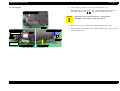
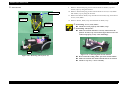
When removing "Housing, Middle", the grounding spring may
detach and drop from "Main Board Unit". If this occurs,
reattach it to its original position referring to the following
figure.
Make sure that "Panel FFC" is securely set and it is not reaching
the upper edge of the rib of "Housing, Middle" as shown in the
figure.
Rib
Keep some clearance here.
Grounding Spring
Figure 2-10. Mounting "Panel FFC"
Make sure that the connector cable of "Power Supply Board" is
Figure 2-8. Reattaching the Ground Spring
"Fixed spring, Core" should be attached with fixing the "Ferrit
securely set in the groove of "Housing, Lower".
Core" as shown below.
Fixed spring, Core
Ferrite Core
Groove
Connector Cable
Figure 2-11. Mounting the Connector Cable
Make sure that "Panel FFC" is not stuck under "Housing,
Figure 2-9. Reattaching the Fixed spring, Core
Middle".
Make sure to tighten up the screws on the back of "Housing,
Middle" in the order as shown in the figure.
DISASSEMBLY AND ASSEMBLY
Disassembly
42
EPSON Stylus Photo R320
Revision B
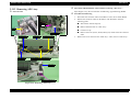
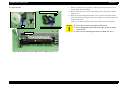
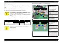
2.3.5 Removing Porous Pad, Paper Guide, Front,
Left, Support
Pars/Units which should be removed before removing "Porous Pad, Paper
Guide, Front"
Paper Support Assy./Preview Monitor Unit/Housing, Upper"/"Housing, Middle
External View
Procedure for Removing
1.
Remove the following 3 types of porous pads from "Paper Guide, Front"
using the tweezers.
• Porous Pad, Paper Guide, Front
• Porous Pad, Paper Guide, Front, Support
• Porous Pad, Paper Guide, Front, Left
C A U T IO N
Porous Pad, Paper Guide, Front, Left
Porous Pad, Paper Guide, Front
Make sure to take "Porous Pad, Paper Guide, Front" cleanly as it
is glued.
Horizontal Direction
: 3-4mm
Vertical Direction: 4 ± 1mm
Horizontal Direction: 1-2mm
Porous Pad, Paper Guide, Front, Support
Horizontal Direction
: 5-6mm
Vertical Direction: 4 ± 1mm
Horizontal Direction: 2-3mm
Figure 2-13. Gluing Point of "Porous Pad, Paper Guide, Front"
Folding Points
Figure 2-12. Removing "Porous Pad, Paper Guide, Front"
DISASSEMBLY AND ASSEMBLY
Disassembly
43
EPSON Stylus Photo R320
Revision B
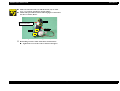
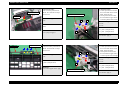
Reinstalling "Porous Pad, Paper Guide, Front"/"Porous Pad,
Paper Guide, Front, Support"
Fold perpendicularly left and right sides of "Porous Pad,
Paper Guide, Front, Support" at the marks and install it to
"Paper Guide, Front". Make sure that the slit engages with
the rib located on the side of "Paper Guide, Front" so that
they will fit securely.
Glue the three bond 1401 at 6 points indicated in
Figure 2-13.
Install "Porous Pad, Paper Guide, Front" in piles. Put it
under the rib, and check if it is securely fit. Adjust the
clearance between "Porous Pad, Paper Guide, Front" and
"Paper Guide, Front" approximately in 0.5 - 1.0mm.
Reinstalling "Porous Pad, Paper Guide, Front, Support"
Insert the foot-parts into the holes of "Paper Guide, Front".
Then, put them under the rib and check if it is securely fit.
C A U T IO N
Do not damage "Porous Pad, Paper Guide, Front, Support".
Do not apply too much adhesive. Do not contaminate "Porous
Pad, Paper Guide, Front, Support" with the adhesive.
Install "Porous Pad, Paper Guide, Front" immediately after
applying the adhesive.
Make sure that the 3 porous pads are fit securely.
DISASSEMBLY AND ASSEMBLY
Disassembly
44
EPSON Stylus Photo R320
Revision B
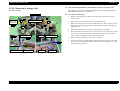
Parts/Units which should be removed before removing "Panel Board"
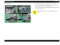
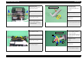
2.3.6 Removing Panel Board
Paper Support Assy./Preview Monitor Unit/Housing, Upper
External View
Procedure for Removing
Board Assy., Panel
2
4
C.B.P 3x8
(5-7kgf•cm)
1.
Remove the screws (x4) which secure "Board Assy., Panel". Then, remove
"Board Assy., Panel".
2.
Remove the screw which secures "Panel Board". Then, remove "Panel Board"
from "Shield Plate, LCD".
3.
Take off the two-sided tapes (x2) which secure "Cover, LCD" from the back
of "Housing, Upper". Then, remove "Cover, LCD".
C A U T IO N
3
Panel Board
LCD Panel
1
Line Mark
When removing "Panel Board Unit", the switch may detach and
Cover, LCD
Two-sided
Tapes
drop. If this occurs, reinstall it referring the figure.
When looking at back side of "Housing, Upper", make sure that
the line mark of "Housing, Upper" securely comes to the position
shown in the figure.
Switch
Rib and
Adjusting Hole
C.B.S 3x6 (4-6kgf•cm)
Match the rib of "Shield Plate, LCD" and the positioning hole of
"Panel Board".
Shield Plate, LCD
Screw "Board Assy., Panel" in the order as shown in the figure.
Figure 2-14. Removing "Panel Board"
DISASSEMBLY AND ASSEMBLY
Do not damage "LCD Panel".
Disassembly
45
EPSON Stylus Photo R320
Revision B
Parts/Units which should be removed before removing "Stacker Assy."
2.3.7 Removing Stacker Assy.
Paper Support Assy./Preview Monitor Unit/Housing, Upper/Housing, Middle
External View
Procedure for Removing
1.
Release the dowel which secures "Stacker Assy." by using a flat-blade
screwdriver or alike. Then, remove "Stacker Assy.".
Match the dowels (x2) of "Stacker Assy." and the installing holes
(x2) of "Housing, Lower".
Right
Left
Stacker Assy.
Installing hole
Dowels
Installing hole
Figure 2-16. Reinstalling "Stacker Assy."
Dowel
Figure 2-15. Removing "Stacker Assy."
DISASSEMBLY AND ASSEMBLY
Disassembly
46
EPSON Stylus Photo R320
Revision B
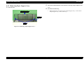
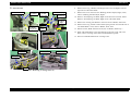
Parts/Units which should be removed before removing "Main Board"
2.3.8 Removing Main Board
Paper Support Assy./Preview Monitor Unit/Housing, Upper/Housing, Middle
External View
Procedure for Removing
Main Board
1.
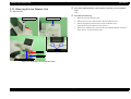
Disconnect the connector cables below from "Main Board".
Table 2-3. Connectors connected to "C582 Main Board"
Two-Sided Tape
Connector
Cable
Panel FFC
Shield Plate, M/B
C.B.P 3x8 (6-8kgf•cm)
C.B.S 3x6 (6-8kgf•cm)
4
3
Main Board
Assy.
Connector
No.
Colour
Number
of Pins
CN3
White
10
Power Supply Board
CN4
White
3
PE Sensor
CN5
Black
3
PG Sensor
CN6
Red
4
Star Wheel/CDR Sensor
CN7
White
2
PG Motor
CN8
Black
4
CR Motor
CN9
White
4
PF Motor
CN10
-
14
CSIC Board/CR Encoder Sensor/PW Sensor
CN11
-
15
Print Head
CN12
-
15
Print Head
Where to Connect
C.B.S 3x6 (4-5kgf•cm)
5
2
1
C.B.P 3x8 (6-8kgf•cm)
Grounding
Spring, M/B
Connector
2.
Take off the two-sided tape which secures "Panel FFC" from "Shield Plate,
M/B".
3.
Remove the screws (x5) which secure "Main Board Assy.". Then, remove
"Main Board Assy.".
4.
Remove "Grounding Spring, M/B" from "Main Board Assy.".
5.
Remove the screw(x1) which seccure "Monitor FFC Holder".
Then remove the "Monitor FFC Holder".
6.
Disconnect the "Panel FFC" and "Monitor FFC" from "Main Board"
connector.
Connector
Monitor FFC Holder
C.B 3x6 (4-6kgf•cm)
Figure 2-17. Removing "Main Board" (1)
DISASSEMBLY AND ASSEMBLY
Disassembly
47
EPSON Stylus Photo R320
Revision B
External View
Housing, Support Slot Assy.
C.B.P 3x6 (4-6kgf•cm)
Dowel
1
C.B 3x6
(4-6kgf•cm)
C.B.S 3x4 (4-6kgfocm)
Shield Plate, M/B
1
4
5
8
7
C.B 3x6
(4-5kgf•cm)
9.
Remove the screws (x8) which secure "Shield Plate, M/B". Then, remove
"Shield Plate, M/B".
Reinstalling "Housing, Support Slot Assy."
Match the dowels (x2) of "Housing, Support Slot Assy." and
Reinstalling "Panel FFC"
Make sure to match "Panel FFC" with the lateral face of
3
C.B.S 3x4
(4-6kgf•cm)
Remove the screw(x1) which secure "Positioning spring, M/B". Then remove
the "Positioning spring, M/B".
the positioning holes of Shield Plate, M/B".
Screw in the order as shown in Figure 2-17.
6
2
8.
Reinstalling "Main Board"/"Shield Plate, M/B"
Screw in the order as shown in Figure 2-18.
C.B.P 3x6 (4-6kgf•cm)
Positioning spring, M/B
Remove the screws (x2) which secure "Housing, Support Slot Assy.". Then,
remove "Housing, Support Slot Assy.".
10. Remove the screws (x7) which secure "Main Board". Then, remove "Main
Board".
2
Dowel
7.
C.P 2.5x6 (3-5kgf•cm)
C.B 3x6 (4-6kgf•cm)
"Shield Plate, M/B" and then attach it to "Main Board
Assy." with a two-sided tape.
C.P 3x4
(3-5kgf•cm)
C.B 3x6 (4-6kgf•cm)
6
4
2
Two-sided Tape
Positioning Point
C.B.S 3x10 (4-6kgf•cm)
7
C.B.S 3x6 (4-6kgf•cm)
3
1
C.B 3x6 (4-6kgf•cm)
Figure 2-19. Routing "Panel FFC"
5
Main Board
Figure 2-18. Removing "Main Board" (2)
DISASSEMBLY AND ASSEMBLY
Disassembly
48
EPSON Stylus Photo R320
Revision B
Reattaching the Main Board Assy
Connector cable for "Star Wheels/CDR Sensor" should be
A D J U S T M E N T
R E Q U IR E D
routed as shown below.
When having replaced "Main Board", implement the
adjustment in the following order. (Refer to Chapter 3
"ADJUSTMENT")
When possible to read data from the old board
1.
EEPROM data copy
When impossible to read from the old board
1.
Replace "Waste Ink Pads" with new one.
(To count the amount of the waste ink)
2. Market Setting
3. USB ID Input
4. Waste Ink Pad Counter
5. Head ID Input
6. First Dot Adjustment
7. PW Sensor Adjustment
8. Head Angular Adjustment
9. Bi-D Adjustment
10. Offset Input for CR Motor Calorific Limitation
Connector Cable
Figure 2-20. Routing connector cable
Screw in the order as indicated at Figure 2-17.
DISASSEMBLY AND ASSEMBLY
Disassembly
49
EPSON Stylus Photo R320
Revision B
Parts/Units which should be removed before removing "ASF Assy."
2.3.9 Removing ASF Assy.
Paper Support Assy./Preview Monitor Unit/Housing, Upper/Housing, Middle/
Main Board Unit
External View
C.B.S
C.B.S
(P4) 3x6
3x8 (5-7kgf.cm)
(5-7kgf•cm)
C.B.S (P4) 3x8 (8-10kgf•cm)
Procedure for Removing
2
3
1.
Take off the Acetate Tape. Then remove connector cable of "PF Motor" and
"PG Motor" from the hook on "ASF Assy".
2.
Remove the screws (Screw, Frame, Main) (x3) which secure connector cable
of "PF Motor" and "PG Motor". Then release the connector cable.
3.
Remove the screws (x5) which secure "ASF Assy.". Then, remove "ASF
Assy." to the back of the printer.
Hook
4
5
4
C.B.P 3x8 (5-7kgf.cm)
C.B.P 3x8 (5-7kgf•cm)
ASF Assy.
3
Screw, ASF
(4-5kgfcm)
Acetate Tape
Connector Cable
2
1
Screw, Frame, Main (5-7kgf.cm)
C.B.S 3x6 (5-7kgf•cm)
1
Figure 2-21. Removing "ASF Assy." (1)
DISASSEMBLY AND ASSEMBLY
Disassembly
50
EPSON Stylus Photo R320
Revision B
External View
4.
Open "Hopper" and then remove "Compression Spring, 2.51".
5.
Bow slightly down "Paper Back Lever" and release the dowels (x2) on the
both sides in the order of 1 , 2 . Then, remove "Paper Back Lever".
Compression Spring, 2.51
C A U T IO N
Hopper
Compression Spring, 0.31
Extension Spring, 0.45
Roller, Retard Assy.
When remove the "Paper Back Lever", "Compression
Spring0.31" comes off. Be careful to not loose it.
6.
Remove the screws (x2) which secure "Support Plate, Frame, ASF".
7.
Release the hooks (x2) which secure "Extension Spring, 0.45". Then, remove
"Roller, Retard Assy.".
Hools
2
1
Dowel
Dowels
Support Plate,
Frame, ASF
C.B.P 3x6 (3-5kgf•cm)
Paper Back Lever
Figure 2-22. Removing "ASF Assy." (2)
DISASSEMBLY AND ASSEMBLY
Disassembly
51
EPSON Stylus Photo R320
Revision B
When reassembling "ASF Assy."
Make sure that "Extension Spring, 0.45" is hooked on
Reinstalling "ASF Assy."
Install "Compression Spring, 2.51" on "Hopper", then
"Frame, ASF" and "Roller, Retard Assy.".
Check if "Torsion Spring, 6.45" is correctly installed on
"Paper Back Lever" and "Frame, ASF".
check if "Hopper" moves smoothly.
Screw in the order as shown in the figure.
Make sure that there is no gap between "ASF Assy." and
"Frame, Main".
Reattaching connector cable of PF Motor and PG Motor
Tighten the screws in the order as shown in the figure.
A D J U S T M E N T
R E Q U IR E D
Torsion Spring, 6.45
When having replaced "ASF Assy.", apply G-46 grease to the
specified points in adequate dose. (Refer to Chapter 4
"MAINTENANCE")
When having replaced or removed "ASF Assy.", implement the
adjustment in the following order. (Refer to Chapter 3
"ADJUSTMENT")
1.
Figure 2-23. Reinstalling "Torsion Spring, 6.45"
First Dot Adjustment
Check if "Paper Back Lever" and "Roller, Retard Assy."
move smoothly.
Do not touch the cork of "Hopper".
Screw the "Support Plate, Frame, ASF" in the order as
indicated below.
1
2
Figure 2-24. Reinstalling "Support Plate, Frame, ASF"
DISASSEMBLY AND ASSEMBLY
Disassembly
52
EPSON Stylus Photo R320
Revision B
Parts/Units which should be removed before removing "Holder, Shaft Assy."
2.3.10 Removing Holder, Shaft Assy.
Paper Support Assy./Preview Monitor Unit/Housing, Upper/Housing, Middle/
Main Board Unit/
ASF Assy.
External View
2
Cable, Head
Procedure for Removing
80-digits Side
Dowel
Paper Guide,
Upper
PE Sensor Lever
Carriage Unit
Ribs
2
C.B.S 3x6
(6-8kgf•cm)
1.
Move "Carriage Unit" toward 80-digits Side.
2.
Remove the screws (x2) which secure "Holder, Shaft Assy.".
3.
Pull "Holder, Shaft Assy." upward and release the hooks ( 1 : x2) with the
tweezers or alike. Then, Release the dowel from "Ink System Frame".
4.
Looking at the printer from its back side, press down "Paper Guide, Upper" on
the left, and release "PE Sensor Lever" from the slot. Remove "Holder, Shaft
Assy." by sliding it to the right.
Holder, Shaft Assy.
C A U T IO N
5.
Be careful not to damage "PE Sensor Lever" and "Paper Guide,
Upper" when removing them since "PE Sensor Lever" contacts
with "Paper Guide, Upper".
Release "Cable, Head" from the hooks ( 2 : x7) of "Holder, Shaft Assy.".
1
Figure 2-25. Removing "Holder, Shaft Assy." (1)
DISASSEMBLY AND ASSEMBLY
C A U T IO N
Disassembly
Do not damage "Cable, Head".
53
EPSON Stylus Photo R320
Revision B
External View
Removing "LD Roller"
Paper, Block
1.
Release the dowels (x2) which secure "Paper, Block". Then, remove "Paper,
Block".
2.
Release the dowels (x2) which secure "Shaft, LD Roller". Then, remove
"Shaft, LD Roller" and "Clutch" together from "Holder, Shaft, LD Roller".
3.
Remove "LD Roller" from "Shaft, LD Roller".
Dowel
Dowel
C A U T IO N
Do not touch "LD Roller" with bare hands.
Dowel
Dowel
Reinstalling "LD Roller"
Make sure to match the direction (
Holder, Shaft, LD Roller
Shaft, LD Roller
Mark) indicated on
"Shaft, LD Roller" with the direction ( Mark) indicated
on the back side of "LD Roller".
PE Sensor Board
Clutch
mark on "LD Roller"
Hook
LD Roller
Extension Spring, 0.143
Spur Gear, 36.8
Torsion Spring, 0.22
Lever Sensor, PE
mark on "Shaft, LD Roller"
Figure 2-26. Removing "Holder, Shaft Assy." (2)
DISASSEMBLY AND ASSEMBLY
Figure 2-27. Reinstalling "LD Roller"
Disassembly
54
EPSON Stylus Photo R320
Revision B
Reinstalling "Clutch"
Make sure that the dowel of "Shaft, LD Roller" is fitted in
Reinstalling "Holder, Shaft Assy."
Check if the hooks (x2), the dowel and the ribs (x5) of
the installing hole of "Clutch".
Make sure that "Extension Spring, 0.143" is securely set on
the hooks of "Clutch" and "Shaft, LD Roller".
Do not set "Extension Spring, 0.143" in twisted form.
Make sure that "Clutch" rotates correctly.
"Holder, Shaft Assy." are correctly secured.
Check if the connector cable of "PE Sensor" and "Cable,
Head" are installed at the correct position of "Holder, Shaft
Assy.".
Do not touch "LD Roller" with bare hands.
Do not damage the teeth of "Spur Gear, 36.8" and
"Combination Gear, 27.2, 19.2".
Reinstalling "Shaft, LD Roller"
Do not touch "LD Roller" with bare hands.
Check if the straight part of "Torsion Spring, 137.7" is set
Spur Gear, 36.8
between the 2 cams of "Shaft, LD Roller".
Torsion Spring, 137.7
Combination Gear, 27.2, 19.2
Figure 2-29. "Spur Gear, 36.8" and "Combination Gear, 27.2, 19.2"
Screw in the order as indicated below.
Make sure that the straight part of "Torsion
Spring, 137.7" is set between the two cams.
LD Roller
Holder, Shaft Assy.
Figure 2-28. Position of "Torsion Spring, 137.7"
1
2
Figure 2-30. Reinstalling "Holder, Shaft Assy."
A D J U S T M E N T
R E Q U IR E D
DISASSEMBLY AND ASSEMBLY
Disassembly
When having replaced "Shaft, LD Roller", apply G-46 grease to
the specified points in adequate dose. (Refer to Chapter 4
"MAINTENANCE")
55
EPSON Stylus Photo R320
Revision B
Procedure for Removing
2.3.11 Removing CR Motor
External View
Carriage Unit
1.
Disconnect the connector cable of "CR Motor" from the connector (CN8) of
"Main Board".
2.
Release the carriage lock with the tweezers or alike, then move "Carriage
Unit" to the centre of the printer.
3.
Push "Pulley, Driven" in the direction of the arrow and loosen the tension of
"Timing Belt". Then, remove "Timing Belt" from the pinion gear of "CR
Motor".
4.
Remove the screws (x2) which secure "CR Motor". Then, remove "CR
Motor".
CN8
Carriage Lock
C A U T IO N
Puller, Driven
Do not damage the pinion gear when removing "CR Motor".
C.C 3x4 (3.5-4.5kgf•cm)
1
2
Make sure to screw "CR Motor" in the order as shown in the
figure.
Timing Belt
CR Motor
Make sure that there is no gap between "CR Motor" and
"Frame, Main".
Make sure that the part on which "CR Motor" Lot number is
Figure 2-31. Removing "CR Motor"
printed is face-up.
Parts/Units which should be removed before removing "CR Motor"
Paper Support Assy./Preview Monitor Unit/Housing, Upper/Housing, Middle
A D J U S T M E N T
R E Q U IR E D
When having removed or replaced "CR Motor", implement the
adjustment in the following order. (Refer to Chapter 3
"ADJUSTMENT")
1.
2.
3.
4.
5.
DISASSEMBLY AND ASSEMBLY
Disassembly
First dot Adjustment
PW Sensor Adjustment
Head Angular Adjustment
Bi-D Adjustment
Offset Input for CR Motor Calorific Limitation (When
Replaced)
56
EPSON Stylus Photo R320
Revision B
Parts/Units which should be removed before removing "APG Assy."
2.3.12 Removing APG Assy.
Paper Support Assy./Preview Monitor Unit/Housing, Upper/Housing, Middle
External View
Procedure for Removing
1.
Disconnect the connector cable of "PG Motor" from CN7 of "Main Board".
2.
Release the connector cables of "PF Motor" and "PG Motor" from the
following points.
Take off the Acetate Tape(x2).
Hook
Remove from the hook on "ASF Assy".
CN7
Cut the tie wrap
Remove the screw (Screw, Frame, Main) (x3) which secure the connector
Acetate Tape
cable.
Acetate Tape
ASF Assy.
3
Tie wrap
Connector Cable
2
3.
Remove the screw which secures "APG Assy.". Then, remove "APG Assy.".
1
Screw, Frame, Main (5-7kgf.cm)
APG Assy.
C.B.S 3x6 (6-8kgf•cm)
Figure 2-32. Removing "APG Assy."
DISASSEMBLY AND ASSEMBLY
Disassembly
57
EPSON Stylus Photo R320
Revision B
Make sure that the hooks (x2) and the dowels (x2) of "APG
Assy." are securely attached to "Frame, Main".
Check if the part indicated in the following figure is inserted in
the slits of "Frame, Main".
It has to be inserted in the
slit of "Frame, Main"
Hook
APG Assy.
Dowel
Figure 2-33. Reinstalling "APG Assy."
Reattaching connector cable of PF Motor and PG Motor
Tighten the screws in the order as shown in the figure.
DISASSEMBLY AND ASSEMBLY
Disassembly
58
EPSON Stylus Photo R320
Revision B
2.3.13 Removing Print Head
External View
4.
Slightly inflect the lower part of "Holder, FFC", release the hooks (x3) by
sliding it downward. Then, remove "Holder, FFC".
5.
Release the hooks (x2) which secure "Holder, IC", and remove "Holder, IC"
upward.
6.
Remove the screws (x2) which secure "Print Head" with Phillips screwdriver
(No.1).
7.
Disconnect "Cable, Head" from the connector of "Print Head" while slightly
lifting "Print Head". Then, remove "Print Head".
Carriage Unit
Hooks
Holder, FFC
C A U T IO N
Carriage Lock
C.B.P 2.5x6 (3-5kgf•cm)
Hooks
Do not touch and/or damage the nozzle surface of "Print Head"
when handling it.
Cable, Head
Check if "Head FFC" is correctly connected to the connector of
1
Holder, IC
"Print Head".
Print Head
Check if "Print Head" is correctly set to "Carriage Unit".
2
Screw the "Print Head" in the order as indicated the Figure.
C.B.B (P2) 2.5x8 (3-5kgf•cm)
A D J U S T M E N T
R E Q U IR E D
Figure 2-34. Removing "Print Head"
Parts/Units which should be removed before removing "Print Head".
adjustment in the following order.
(Refer to Chapter 3 "ADJUSTMENT")
1.
2.
3.
4.
5.
6.
7.
Paper Support Assy./Preview Monitor Unit/Housing, Upper/Housing, Middle
Procedure for Removing
1.
Remove all the ink cartridges from "Carriage Unit".
2.
Release "Carriage Lock" with the tweezers or alike, then move "Carriage
Unit" to the centre of the printer.
3.
Remove the screw (x1) which secures "Holder, FFC" with the No. 1 driver.
DISASSEMBLY AND ASSEMBLY
When having removed or replaced "Print Head", implement the
Disassembly
Ink Charge (When Replaced)
Head ID Input (When Replaced)
First Dot Adjustment
PW Sensor Adjustment
Head Angular Adjustment
Bi-D Adjustment
Offset Input for CR Motor Calorific Limitation
59
EPSON Stylus Photo R320
Revision B
Parts/Units which should be removed before removing "Carriage Unit"
2.3.14 Removing Carriage Unit
Paper Support Assy./Preview Monitor Unit/Housing, Upper/Housing, Middle/
Main Board Unit/APG Assy./Print Head
External View
Procedure for Removing
Guide Plate, CR
Fixed
Spring, CR
Shaft, Left
C.B.S 3x6 (7-9kgf•cm)
3
4
6
Hook
2.
Remove the screws (x6) which secure "Guide Plate, CR".
3.
Release the ribs (x2) which secure "Guide Plate, CR". Then, remove "Guide
Plate, CR" while stepping aside the hook which has secured "Fixed Spring,
CR Shaft, Left".
4.
Remove the right side of "CR Scale" from "Holder, Scale Right".
5.
Pull out "CR Scale" from the back of "Carriage Unit" to the left. Then, release
"CR Scale" from one of two hooks of "Holder, Scale, Left" first, and next
release "Extension Spring, 3.289" from the other hook.
6.
Remove "Extension Spring, 3.289" from "CR Scale".
7.
Loosen the tension of "Timing Belt" by pushing "Pulley, Driven" to the right.
Then, remove "Timing Belt" from the pinion gear of "CR Motor" first, and
then from "Pulley, Driven".
Rib
Holder, Scale Left
CR Scale
Holder, Scale Right
Hook
Hook
Extension Spring, 3.289
Remove "Fixed Spring, CR Shaft, Left" by releasing it from the hook of
"Frame, Main".
5
Rib
Hook
1.
1
2
Pulley, Driven
Timing Belt
Pinion Gear
Figure 2-35. Removing "Carriage Unit" (1)
DISASSEMBLY AND ASSEMBLY
Disassembly
60
EPSON Stylus Photo R320
Revision B
External View
E Ring
Flat Washer
Holder, Scale Left
Bushing,
Parallel
Adjust, Right
Holder, Scale, Right
C.B.S (P4) 3x6
(6-8kgf•cm)
Fixed Spring,
CR Shaft,
Right
E Ring
E Ring
Flat Washer
Spring Washer
Cam, CR,
Right
Hook
Remove the E ring, "Holder, Scale Right" and "Cam, CR, Right" from the
right side of "CR Guide Shaft".
9.
Remove the screw which secures "Bushing, Parallel Adjust, Right", Then,
remove "Bushing, Parallel Adjust, Right".
10. Remove "Fixed Spring, CR Shaft, Right" from the hook of "Frame, Main".
Remove "Fixed Spring, CR Shaft, Right" from "CR Guide Shaft".
11. Remove the "E Ring, Flat Washer" which secure the "Holder, Scale Left".
12. Remove the E ring, the flat washer and the spring washer from the left side of
"CR Guide Shaft". Then, remove "Holder, Scale, Left"
13. Release "Cable, Head" from the hooks (x8) of "Holder, Shaft Assy.".
14. Slide "CR Guide Shaft" to the right and pull it out from "Cam, CR, Left".
Then, remove "Carriage Unit" and "CR Guide Shaft" together.
CR Guide Shaft
15. Pull out "CR Guide Shaft" from "Carriage Unit".
Hooks
Cable, Head
8.
Cam, CR, Left
CR Guide Shaft
Holder, Shaft
Assy.
Hooks
Figure 2-36. Removing "Carriage Unit" (2)
DISASSEMBLY AND ASSEMBLY
Disassembly
61
EPSON Stylus Photo R320
Revision B
External View
16. Remove the screw which secures "Bushing, Parallel Adjust, Left". Then,
remove "Bushing, Parallel Adjust, Left".
Bushing, Parallel
Adjust, Right
C.B.S (P4) 3x6
(6-8kgf•cm)
Holder, FFC ; B
17. Remove "Timing Belt" from "Carriage Unit".
2
C.P.B (P1) 1.7x5
(1.5-2.5kgf•cm)
18. Remove the screws which secure "Holder, FFC; B". Then, remove "Holder,
FFC; B".
19. Remove "Cable, Head" from the connectors of "CSIC Board" and "CR
Encoder Sensor Board". Then, remove "Cable Head" from "Carriage Unit".
1
Removing "Pulley, Driven"
1.
Remove "Extension Spring, 26.46" from "Pulley Driven" and the hook of
"Frame, Main" by using a flat-blade screwdriver. Then, remove "Extension
Spring, 26.46".
2.
Slide "Pulley, Driven" in the direction of the arrow. Then, remove "Frame,
Main" from the slot.
Timing Belt
CSIC Board
Connector
Removing "CR Encoder Sensor Board"
1.
Remove the screw which secures "CR Encoder Sensor Board" with Phillips
screwdriver (No.0). Disconnect "PW Sensor FFC" from the connector of "CR
Encoder Sensor Board". Then, remove "CR Encoder Sensor Board".
CR Encoder
Sensor Board
CR Encoder Sensor Board
PW Sensor FFC
Extension Spring, 26.46
Pulley, Driven
2
1
C.P.B (P1)1.7x5
(1.5-2.5kgf.cm)
Connector
Slot
Figure 2-37. Removing "Carriage Unit" (3)
DISASSEMBLY AND ASSEMBLY
Disassembly
62
EPSON Stylus Photo R320
Revision B
External View
Removing "PW Sensor Board"
1.
Cap, PW Sensor
Release the hooks (x3) which secure "Cap, PW Sensor". Then, remove "Cap,
PW Sensor".
PW Sensor Board
C A U T IO N
Connector
When removing "Cap, PW Sensor", "PW Sensor Board" will be
free. Therefore, take care not to damage "PW Sensor Board".
Hooks
2.
Removing "CSIC Board"
Torsion Spring, Lever, Cartridge
Hook
Dowel
Guide, IC
Lever, Cartridge
Slot and Dowel
1.
Remove "Torsion Spring, Lever, Cartridge" from the hook and the dowel of
"Guide, IC".
2.
Remove the dowel of "Lever, Cartridge" from the slot on the right side of
""Guide, IC" by using the tweezers. Then, remove "Lever, Cartridge.
3.
Remove the screws (x2) which secure "Guide, IC", then release the hook with
the tweezers. And remove "Guide, IC".
4.
Release the hooks (x2) which secure "CSIC Board", then push up "CSIC
Board" from the slot located on the bottom of "Carriage Unit" with a flatblade screwdriver or alike. Finally, remove "CSIC Board".
C.B.P 2.5x8 (3-5kgf•cm)
Electric Pole
C A U T IO N
Hooks
1
Pull out "PW Sensor Board" from the slot of "Carriage Unit". Then, remove
"PW Sensor FFC" from the connector of "PW Sensor Board" and remove
"PW Sensor Board" and "PW Sensor FFC".
Do not damage the electric pole with the flat-blade screwdriver or
alike when removing "CSIC Board".
2
CSIC Board
Hook
Slot
Figure 2-38. Removing "CR Unit" (4)
DISASSEMBLY AND ASSEMBLY
Disassembly
63
EPSON Stylus Photo R320
Revision B
Reinstalling "Guide, IC"
Screw in the order as shown in the figure.
Reinstalling "Carriage Unit"
Check if "Timing Belt" is correctly set to the installing
groove of "Carriage Unit".
Check if "Grounding Plate, Head" is installed to the proper
position of "Carriage Unit".
Reinstalling "CSIC Board"
Check if "CSIC Board" is secured correctly.
Reinstalling "PW Sensor Board"
Check if "PW Sensor FFC" is correctly connected.
Check if "PW Sensor Board" is correctly secured with
Timing Belt
Grounding Plate, Head
"Cap, PW Sensor".
Reinstalling "CR Encoder Sensor Board"
Check if "CR Encoder Sensor Board" is correctly secured.
Check if "CR Encoder Sensor Board" is correctly
connected.
Reinstalling "Holder, FFC ; B"
Screw in the order as shown in the figure.
Groove
Figure 2-40. Installing Position of "Grounding Plate, Head"
Reinstalling "Holder, Scale, Right (Left)"
Check if "Slider, Holder, Scale" is set.
Holder, Scale, Right
Reinstalling "CR Scale"
Make sure that "Extension Spring, 3.289" is not twisted.
Make sure to pass "CR Scale" through the slit of "CR
Holder, Scale, Left
Encoder Sensor".
Make sure to install "CR Scale" with the cut-part on the left
edge up.
Cut-Part
Figure 2-41. Reinstalling "CR Scale"
Slider, Holder, Scale
Reinstalling "Guide, CR"
Screw in the order as shown in the figure.
Figure 2-39. Reinstalling "Slider, Holder, Scale"
DISASSEMBLY AND ASSEMBLY
Disassembly
64
EPSON Stylus Photo R320
A D J U S T M E N T
R E Q U IR E D
Revision B
When replacing the following parts or components with new
ones, apply specified grease in its adequate dose. (Refer to
Chapter 4 "MAINTENANCE")
Cam, CR, Right/Left
CR Guide Shaft
Holder, Scale, Right/Left
Pulley, Driven Assy.
When having removed or replaced "Carriage Unit" or "CR
Guide Shaft", implement the adjustment in the following order.
(Refer to Chapter 3 "ADJUSTMENT")
1.
2.
3.
4.
5.
6.
PG Adjustment
First Dot Adjustment
PW Sensor Adjustment
Head Angular Adjustment (Only "Carriage Unit")
Bi-D Adjustment
Offset Input for CR Motor Calorific Limitation (When
Replace "CR Guide SHaft")
When having removed or replaced "PW Sensor", implement the
adjustment in the following order. (Refer to Chapter 3
"ADJUSTMENT")
1.
PW Sensor Adjustment
DISASSEMBLY AND ASSEMBLY
Disassembly
65
EPSON Stylus Photo R320
Revision B
Parts/Units which should be removed before removing "Paper Guide,
2.3.15 Removing Paper Guide, Upper
Upper"
External View
Paper Support Assy./Preview Monitor Unit/Housing, Upper/Housing, Middle/
Main Board Unit/ASF Assy./Holder, Shaft Assy.
Procedure for Removing
Paper Guide, Upper
Torsion Spring, 122.2
Paper Guide, Lower
Roller PF Assy.
1.
Move "Carriage Unit" to the home position.
2.
Put a transparency between "Paper Guide, Upper" and "Roller PF Assy.".
3.
Release "Torsion Spring, 122.2" (x3) from the hook ( 1 : 1 each) of "Frame,
Main", then pull it out toward you.
4.
Release the hooks ( 2 : 2 each) which secure "Paper Guide, Upper" (x3)
upward. Then, release the dowels (2 each) while slightly holding up "Paper
Guide, Upper".
5.
Press down "Paper Guide, Lower" and pull out "Paper Guide, Upper" (x3)
toward you while avoiding the ribs (2 each) of "Frame, Main"
Transparency
2
Hooks
1
Hook
There are 2 types of "Driven Rollers" of "Paper Guide, Upper".
Install them as shown in the following figure.
Rib
Rib
Dowels
Figure 2-42. Removing "Paper Guide, Upper"
Driven Roller (Grey)
Driven Roller (White)
Figure 2-43. Installing Position of "Paper Guide, Upper"
DISASSEMBLY AND ASSEMBLY
Disassembly
66
EPSON Stylus Photo R320
2.3.16
Revision B
Removing Printer Mechanism/
Housing, Lower
External View
2 ± 1mm
C.B 3x6 (4-5kgf•cm)
C.B.S 3x6 (6-8kgf•cm)
C.B.P 3x10 (6-8kgf•cm)
5
4
Acetate Tape
Hooks
2
1
C.B.P 3x8 (4-5kgf•cm)
Hook
Handling Position
3
Paper Guide, CDR
C.B.P 3x10 (6-8kgf•cm)
2
1
3
Figure 2-45. Removing "Printer Mechanism"/"Housing, Lower" (2)
Parts/Units which should be removed before removing "Printer
Screw, Frame, Main (6-8kgf•cm)
Combination
Gear, 27.2, 19.2
Mechanism"/"Housing, Lower"
Hook (Under the tube)
Paper Support Assy./Preview Monitor Unit/Housing, Upper/Housing, Middle/
Main Board Unit/ASF Assy./Holder, Shaft Assy.
Lever, Change
Procedure for Removing
1.
Move "Carriage Unit" to the centre of the printer.
2.
Remove the screws (x3) which secure "Paper Guide, CDR".
3.
Remove the screws (x5) which secure "Printer Mechanism".
4.
Take off the acetate tape and release the connector of "Star Wheel/CDR
Sensor".
5.
Cut off the tie wrap and release the connector cable.
6.
Release the hooks (x4) which secure "Printer Mechanism". Then, hold the
both right and left upper edges of "Frame, Main" and remove "Printer
Mechanism" upward.
Tie wrap
Figure 2-44. Removing "Printer Mechanism"/"Housing, Lower" (1)
DISASSEMBLY AND ASSEMBLY
Disassembly
67
EPSON Stylus Photo R320
C A U T IO N
Revision B
When lifting up "Printer Mechanism", "Lever, Change" and
"Combination Gear, 27.2, 19.2" may detach and drop. Take care
not to drop and damage them.
Reinstalling "Printer Mechanism"
For this printer, "Housing, Lower" is the standard to
correctly install each part of "Printer Mechanism".
In order to ensure the accuracy for installing, it is necessary
to manage the reference position for "Frame, Main"
installation in X, Y and Z direction as shown in the figure
below. If every part is set correctly, "Printer Mechanism"
can be secured with the hooks (x4).
[X-axis]
• Make sure that "Frame, Main" is installed correctly to the
groove of "Housing, Lower".
• Make sure that there is no gap between "Frame, Main"
and "Housing, Lower".
[Y-axis]
Make sure that the slot of "Frame, Main" is correctly
installed to the projection of "Housing, lower".
[Z-axis]
• Make sure that there is no gap between "Frame, Main"
and "Housing, Lower"
• Make sure that the left side of "Printer Mechanism" is
correctly secured with the hooks (x2).
When lifting up "Printer Mechanism", take care not to leak and
drip ink from the end of "Waste Ink Tube" ("Waste Ink Pads"
side).
To prevent "Frame, Main" from warping, do not lift "Printer
Mechanism" holding the places other than specified.
W A R N IN G
When installing "Printer Mechanism" to "Housing, Lower", pass
"Waste Ink Tube" through the hook indicated in the figure below,
and securely set it in the groove, so that "Porous Pad, Ink Eject,
Upper, Support" will not lift up above the tube. If installed
insecurely, it may cause the ink leakage.
Porous Pad, Ink Eject, Upper, Support
Hook
Right
Left
Waste Ink Tube
Hooks
Figure 2-46. Reinstalling "Waste Ink Tube"
Hooks
X-axis :
Y-axis :
Z-axis :
(4 points)
(1 point)
(4 points)
Figure 2-47. Reference position for installing "Frame, Main"
DISASSEMBLY AND ASSEMBLY
Disassembly
68
EPSON Stylus Photo R320
Revision B
Make sure that "Waste Ink Pads" (x6) are set correctly to
the rib and the dowel of "Housing, Lower".
Waste Ink Pad, Small
Waste Ink Pad, Upper (Top)
Waste Ink Pad, Lower (Bottom)
Figure 2-49. Reinstalling "Waste Ink Pads" (2)
After checking "Waste Ink Tube" is under "Waste Ink Pad,
Lower", put the jig on the indicated points in the figure
below, then install "Porous Pad, Ink Eject, Upper, Support".
Porous Pad, Ink Eject,
Upper, Support
Waste Ink Pad, Lower
Jig
Adjusting Point
Cap, Ink Pad, Lower,
Small (Top)
Cap, Ink Pad, Lower,
Large (Bottom)
Figure 2-50. Reinstalling "Porous Pad, Ink Eject, Upper, Support"
Figure 2-48. Reinstalling "Waste Ink Pads" (1)
DISASSEMBLY AND ASSEMBLY
Disassembly
69
EPSON Stylus Photo R320
Revision B
Screw "Printer Mechanism" and "Paper Guide, CDR" in
the order as shown in the figure.
Make sure that "Waste Ink Tube" is not squashed or
pressed.
Check if "Cap Assy." moves smoothly.
A D J U S T M E N T
R E Q U IR E D
When having replaced "Waste Ink Pads" with new ones,
implement the following adjustment. (Refer to Chapter 3
"ADJUSTMENT")
Waste Ink Pad Counter
DISASSEMBLY AND ASSEMBLY
Disassembly
70
EPSON Stylus Photo R320
Revision B
Procedure for Removing
2.3.17 Removing Power Supply Unit
External View
Shield Plate, Upper
1.
Remove the screw which secures "Power Supply Unit". Then, Remove
"Power Supply Unit".
2.
Remove the screws (x5) which secure "Shield Plate, Upper".
3.
Release the hooks (x2) which secure "Shield Plate, Upper", and then remove
"Shield Plate, Upper".
4.
Remove the screws (x4) which secure "PSB/PSE Board", and then remove
"PSB/PSE Board".
2
1
3
Power Supply Unit
C.B.P 3x10 (6-8kgf•cm)
Reinstalling "PSB/PSE Board"
Make sure to screw in the order as shown in the figure.
C.B.S 3x6 (6-8kgf•cm)
C.B.S 3x6 (6-8kgf•cm)
Reinstalling "Shield Plate, Upper"
Check if the "Power connector cable" is in between the two
C.B.S 3x6 (6-8kgf•cm)
1
4
shield plates.
Check if "Shield Plate, Upper" is correctly installed.
Make sure to screw in the order as shown in the figure.
5
A D J U S T M E N T
R E Q U IR E D
4
Hooks
3
2
When replacing "Power Supply Unit" with a new one,
implement the following adjustment. (Refer to Chapter 3
"ADJUSTMENT")
Offset Input for CR Motor Calorific Limitation
Figure 2-51. Removing "Power Supply Unit"
Parts/Units which should be removed before removing "Power Supply Unit"
Paper Support Assy./Preview Monitor Unit/Housing, Upper/Housing, Middle/
Main Board Unit/ASF Assy./Holder, Shaft Assy./Printer Mechanism
DISASSEMBLY AND ASSEMBLY
Disassembly
71
EPSON Stylus Photo R320
Revision B
2.3.18 Removing CDR Guide Assy.
External View
Hooks
C.B.P 3x6 (5-7kgf•cm)
2
Support Plate, Frame, Main
C.B.S 3x6 (7-9kgf•cm)
1
CDR Guide, Lower
1
Hooks
2
Figure 2-53. Removing "CDR Guide Assy." (2)
Acetate Tape
Parts/Units which should be removed before removing "CDR Guide Assy."
Connector Cable
CDR Guide Assy.
Link, CDR Right
Paper Support Assy./Preview Monitor Unit/Housing, Upper/Housing, Middle/
Main Board Unit/ASF Assy./Holder, Shaft Assy./APG Assy./
Print Head/Carriage Unit/Printer Mechanism
C.B.S 3x6 (6-8kgf•cm)
C.B.S 3x6 (6-8kgf•cm)
Procedure for Removing
1
2
Ribs
Take off the acetate tape and release the connector cable of "Star Wheel/ CDR
Sensor".
2.
Remove the screws (x2) which secure "Support Plate, Frame, Main". Then,
remove "Support Plate, Frame, Main".
3.
Remove the screws (x3) which secure "CDR Guide Assy.".
4.
Remove the flat washer which secure "Link, CDR Left (Right)" with the
tweezers. Then, Remove "Link, CDR Left (Right)" from "CDR Guide Assy.".
5.
Release the ribs (x7) which secure "CDR Guide Assy.", then remove "CDR
Guide Assy." through the right edge.
6.
Remove the screws (x2) which secure "CDR Guide, Lower".
7.
Slide "CDR Guide, Lower" and then release the hooks (x7). After that,
remove "CDR Guide, Lower".
Ribs
3
Flat Washer
1.
Link, CDR Left
Ribs
Flat Washer
Figure 2-52. Removing "CDR Guide Assy." (1)
DISASSEMBLY AND ASSEMBLY
Disassembly
72
EPSON Stylus Photo R320
Revision B
External View
8.
Remove "Compression Spring, 5.1" and "Lock, Stacker" from "CDR Guide,
Upper".
9.
Release the connector cable of "Star Wheel/CDR Sensor" from the groove of
"CDR Guide, Upper".
Reinstalling "Star Wheel/CDR Sensor"
Match the Shaft (x2) of "CDR Guide, Upper" and the
positioning hole of "Star Wheel/CDR Sensor".
Route the connector cable correctly of "Star Wheel/CDR
Groove
Sensor" referring to the figure.
Reinstalling "CDR Guide, Lower"
Screw in the order as shown in the figure.
Star Wheel/CDR Sensor
Reinstalling "CDR Guide, Upper"
Make sure that the hooks (x2) of "Lock Stacker" are
properly secured by the tension of "Compression Spring,
5.1".
Make sure that "CDR Guide, Upper" is securely secured
with the hooks (x7) of "CDR Guide, Lower" and there is no
gap between "CDR Guide, Upper" and "CDR Guide,
Lower".
Compression Spring, 5.1
Lock, Stacker
Reinstalling "CDR Guide Assy."
Install "CDR Guide Assy." in the order of left edge, right
Hooks
edge and middle.
Match the slot (x6) of "CDR Guide Assy." and the ribs (x6)
of "Frame, Main".
Check if "Link, CDR Left (Right)" is correctly installed.
Check if the connector cable of "Star Wheel/CDR Sensor" is
not interrupting "Link, CDR Right".
Check if "Frame, EJ Assy." works with "CDR Guide Assy."
and moves smoothly.
Shaft and Positioning Hole
Reinstalling "Support Plate, Frame, Main"
Screw in the order as shown in the figure.
Figure 2-54. Removing "CDR Guide Assy." (3)
DISASSEMBLY AND ASSEMBLY
Disassembly
73
EPSON Stylus Photo R320
Revision B
Parts/Units which should be removed before removing "Ink System"
2.3.19 Removing Ink System
Paper Support Assy./Preview Monitor Unit/Housing, Upper/Housing, Middle/
Main Board Unit/ASF Assy./Holder, Shaft Assy./Printer Mechanism
External View
Procedure for Removing
Support Plate,
Frame, Main
Sealing Rubber Part
Hook
Cap Assy.
1.
Take off the acetate tape, then release the connector cable of "Star Wheel/
CDR Sensor".
2.
Remove the screws (x2) which secure "Support Plate, Frame, Main", and
remove "Support Plate, Frame, Main".
3.
Remove the screw which secures "Cap Assy.".
4.
Slide "Cap Assy." inward "Printer Mechanism" and release the dowels
( 1 : x2"). Then, remove "Cap Assy." from the ribs (x2) of "Frame Main".
Acetate Tape
1
Dowels
2
Cleaner Head
1
C.B.S 3x6
(7-9kgf•cm)
C.B.P 3x8
(5-7kgf•cm)
Pump Assy.
Lever, Change Assy.
C A U T IO N
Dowel
Ribs
Do not remove the ink tube which is connected to "Cap Assy."
and "Pump Assy.".
The ink tube cannot be removed from "Pump Assy." since it is
secured with silicon material for the following reasons.
To prevent "Pump Assy." from ink leakage.
To adjust the length of the ink tube extended from "Pump
Dowels
Frame".
Hooks
Combination Gear, 27.2, 19.2
5.
Release the hooks (x3) and the dowels (x3) which secure "Pump Assy.", and
hold "Lever, Change Assy." and all the gears with your finger in order not to
let them drop, then remove "Cap Assy." and "Pump Assy." together.
6.
Remove "Combination Gear, 20.82, 24", "Spur Gear, 27.2", "Lever, Change
Assy." and "Combination Gear, 27.2, 19.2" from "Pump Assy.".
7.
Remove "Spur Gear, 25.6" from "Lever, Change".
8.
Remove "Compression Spring, 2.36" from the dowel of "Lever, Change".
Lever, Change
Spur Gear, 25.6
Combination
Gear, 20.82, 24
Dowels
Spur Gear, 27.2
Silicon Material Part
Compression Spring, 2.36
Figure 2-55. Removing "Ink System" (1)
DISASSEMBLY AND ASSEMBLY
Disassembly
74
EPSON Stylus Photo R320
Revision B
External View
9.
Frame, Cap
Slider, Cap
Remove "Extension Spring, 0.441" from the hooks of "Slider, Cap" and
"Frame, Cap" by using the tweezers.
10. Remove "Extension Spring, 0.788" from the hooks of "Lever, Lock, Slider"
and "Frame, Cap" by using the tweezers.
Lever, Lock, Slider
11. Remove the shaft of "Slider, Cap" from the slot of "Frame, Cap", then remove
"Lever, Lock, Slider".
Extension
Spring, 0.788
12. Remove "Porous, Slider, Cap" from the hook of "Slider, Cap".
Extension
Spring, 0.441
Reinstalling "Lever, Lock, Slider"
Check if it works properly with "Slider, Cap".
Reinstalling "Ink System"
Make sure that the ink tube is correctly connected to the
Hooks
point of "Frame, Cap" shown in the figure below. If it is not
connected properly, it may cause ink leakage.
Porous Pad, Slider, Cap
Hook
Shaft
Figure 2-57. Connecting Point for the ink tube
Figure 2-56. Removing "Ink System" (2)
DISASSEMBLY AND ASSEMBLY
Do not touch the sealing rubber part and "Cleaner Head".
Make sure that the line mark of the ink tube is not twisted.
Check if "Cap Assy." moves smoothly.
Disassembly
75
EPSON Stylus Photo R320
Revision B
Set all of the gears on the shaft of "Pump Frame" correctly,
and then check if they move smoothly.
Make sure that the ink tube is not squashed or pressed.
Install the ink tube to the grooves (x2) at the bottom surface
of "Cap Frame".
Figure 2-58. Installing Point for the ink tube
Reinstalling "Ink System"
Check if "Pump Assy." is correctly secured.
Do not let "Lever, Change", "Combination Gear, 27.2,
19.2", "Spur Gear, 27.2" and "Combination Gear, 20.82,
24" drop and break them.
Reinstalling "Support Plate, Frame, Main"
Screw in the order as shown in the figure.
DISASSEMBLY AND ASSEMBLY
Disassembly
76
EPSON Stylus Photo R320
Revision B
Parts/Units which should be removed before removing "Paper Guide,
2.3.20 Removing Paper Guide, Front/Roller EJ Assy.
Front"/"Roller EJ Assy."
External View
Spur Gear,37.242
PF Timing Belt
Paper Support Assy./Preview Monitor Unit/Housing, Upper/Housing, Middle/
Main Board Unit/ASF Assy./Holder, Shaft Assy./APG Assy./Print Head/
Carriage Unit/Printer Mechanism/CDR Guide Assy.
Guide, Shaft, Frame EJ, Right
Spur Gear, 41.48
Procedure for Removing
1.
Release the hook of "Link EJ, Right" from the groove of "Guide, Shaft, Frame
EJ, Right". Then, remove "Link EJ, Right".
2.
Remove the flat washer which secures the right side of "Frame EJ Assy.".
3.
Remove "PF Timing Belt" from "Spur Gear, 37.242", then remove "Spur
Gear, 41.48".
4.
Remove "Compression Spring, 1.27" and "Holder, Idle Roller" together with
"PF Timing Belt".
5.
Move back "Carriage Unit" to the home position, and then remove "Frame EJ
Assy." in the direction of the arrow, also in the order indicated in the figure.
Flat Washer
Hook
Compression
Spring, 1.27
Holder, Idle Roller
Link EJ, Right
Guide, Shaft,
Frame EJ, Left
2
1
Extension Spring,
Push Up, Plate, Left
C A U T IO N
Hooks
When removing "Frame EJ Assy.", take care not to damage or
transform "Star Wheels" of "Frame EJ Assy.".
Flat Washer
Frame EJ Assy.
Link EJ, Left
Hooks
6.
Remove the flat washer which secures "Link EJ, Left", then Slide "Link EJ,
Left" to the right.
7.
Remove "Extension Spring, Push Up, Plate, Left" from the hooks of "Guide,
Shaft, Frame EJ, Left" and "Frame, Main".
8.
Release the hooks (Left x3, right x2) which secure "Guide, Shaft, Frame EJ,
Left (Right)". Then, remove "Guide, Shaft, Frame EJ, Left (Right)".
Hook
Figure 2-59. Removing "Paper Guide, Front"/"Roller EJ Assy." (1)
DISASSEMBLY AND ASSEMBLY
Disassembly
77
EPSON Stylus Photo R320
Revision B
External View
9.
Guide, Shaft, Frame EJ, Right
Remove "Extension Spring, Push Up, Plate, Right" from the hooks (x2) of
"Guide, Shaft, Frame EJ, Right".
10. Release the hook which secures "Paper Guide, Front", then remove "Paper
Guide, Front".
Hooks
11. Remove the "Porous Pad, Paper Guide, Front", "Porous Pad, Paper Guide,
Left", and "Porous Pad, Paper Guide, Front, Support"(x3) with tweezers from
"Paper Guide, Front".
(Refer to 2.3.5 Removing Porous Pad, Paper Guide, Front, Left, Support)
Hook
Extension Spring, Push Up, Plate, Left
C A U T IO N
Do not touch "Porous Pad, Paper Guide, Front".
Do not damage the rib located on the upper surface of "Paper
Guide, Front".
Take care not to damage the surface of "Roller, PF Assy.".
Roller, PF Assy.
Paper Guide, Front
Figure 2-60. Removing "Paper Guide, Front"/"Roller EJ Assy." (2)
DISASSEMBLY AND ASSEMBLY
Disassembly
78
EPSON Stylus Photo R320
Revision B
External View
12. Remove "Grounding Spring, EJ Left (Right)" from "Roller EJ Assy.".
13. Release the dowels of both left and right "Bushing, 5" which secure "Roller
EJ Assy.", then turn them in the direction of the arrow.
14. Pull out the right "Bushing, 5" rightward, and pull out the left edge of "Roller
EJ Assy." from the left side of "Frame, Main" and then remove the Assy from
right side of "Frame, Main".
Grounding Spring, EJ Left
Dowel
Dowel
C A U T IO N
Grounding Spring, EJ Right
When removing "Roller EJ Assy.", do not damage the rubber
rollers.
Roller EJ Assy.
Bushing, 5
Rubber Rollers
Bushing, 5
Figure 2-61. Removing "Paper Guide, Front"/"Roller EJ Assy." (3)
DISASSEMBLY AND ASSEMBLY
Disassembly
79
EPSON Stylus Photo R320
Revision B
Reinstalling "Paper Guide, Front"
Make sure that the dowels and the hook of "Paper Guide,
A D J U S T M E N T
R E Q U IR E D
When replacing "Roller EJ Assy.", apply G-26 grease in the
adequate dose to the specified points.
When having removed or replaced "Paper Guide, Front",
Front" are correctly secured to "Frame, Main".
implement the following adjustment. (Refer to Chapter 3
"ADJUSTMANT")
1.
2.
3.
4.
Hook
First Dot Adjustment
PW Sensor Adjustment
Head Angular Adjustment
Bi-D Adjustment
Dowels
Figure 2-62. Reinstalling "Paper Guide, Front"
Make sure that the tabs of "Porous Pad, Paper Guide, Front,
Left" and "Porous Pad, Paper Guide, Front, Support" are
facing straight to downward through the slots of "Paper
Guide, Front".
Make sure that there is no gap between "Paper Guide,
Front" and "Frame, Main".
If any ink leaks on the rib of "Paper Guide, Front", clean it
with a cotton swab. (At this time, take care not to touch
"Porous Pad, Paper Guide, Front" of "Paper Guide, Front"
with the cotton swab.)
Reinstalling "Roller EJ Assy."
Make sure that both left and right "Bushing, 5" are
correctly secured.
Make sure that "Grounding Spring, EJ Left (Right)" is
correctly attached to the both ends of "Roller EJ Assy.".
When installing "PF Timing Belt", do not damage the teeth
of "Spur Gear, 41.48".
Make sure that "Roller EJ Assy." moves smoothly.
DISASSEMBLY AND ASSEMBLY
Disassembly
80
EPSON Stylus Photo R320
Revision B
Procedure for Removing
2.3.21 Removing PF Motor
External View
Spur Gear, 37.242
PF Timing Belt
Spur Gear, 41.48
Pinion Gear
4
1.
Remove "PF Timing Belt" from "Spur Gear, 37.242", then remove "Spur
Gear, 41.48".
2.
Remove "Compression Spring, 1.27" and "Holder, Idle Roller" together with
"Timing Belt".
3.
Remove the nuts (x4) which secure "PF Motor", then remove "PF Motor".
PF Motor
1
C A U T IO N
2
Compression
Spring, 1.27
Holder, Idle Roller
When removing "PF Motor", do not damage the pinion gear.
When removing "PF Motor", "Compression Spring, 1.53" may
detach and drop. Be careful not to lose it.
3
Hexagon Nuts, M3 (5-7kgf•cm)
Compression Spring, 1.53 (Only this point)
Reinstalling "PF Motor"
Make sure to tighten the nuts of "PF Motor" in the order
Spacer Insulator
shown in the figure.
Make sure that there is no gap between "Spacer, Insulator"
and "Frame, Main".
Insulator, Motor, PF
Figure 2-63. Removing "PF Motor"
Parts/Units which should be removed before removing "PF Motor"
Paper Support Assy./Preview Monitor Unit/Housing, Upper/Housing, Middle/
Main Board Unit/ASF Assy./Holder, Shaft Assy./Printer Mechanism
DISASSEMBLY AND ASSEMBLY
Disassembly
81
CHAPTER
3
ADJUSTMENT
EPSON Stylus Photo R320
Revision B
3.1 Adjustment Items and Overview
This chapter describes adjustments to be made after the disassembly/reassembly of this product.
3.1.1 Servicing Adjustment Item List
The adjustment items of this product are as follows. For details of the adjustment items, refer to the detailed procedures and sketches of the adjustment items.
Adjustment items
Table 3-1. Adjustment Items
Function Item
Purpose
Method Outline
Market Setting
At the time of Main Board replacement, this adjustment is made
to write the board common information on a destination basis.
Select and execute this function in the exclusive servicing program to
save the following data into the EEPROM.
Market ID, CSIC Printer ID, D4 Setting (USB, Parallel), First Dot
Adjustment fixed value.
Exclusive
servicing
program
Non-target
USB ID Input
This adjustment is made to allow the PC to recognize the
connected printers individually when multiple printers of the
same model are connected and used with the PC via a USB hub.
Select this function in the exclusive servicing program and enter the
serial numbers of the printers. The correction value is saved to the
specific EEPROM address on the Main Board.
Exclusive
servicing
program
Non-target
Head ID Input
At the time of Print Head replacement, this adjustment is made
to correct head manufacturing variations and eliminate the
individual differences of print quality.
Enter the ID of the Head QR code label applied to the Print Head into
the exclusive servicing program to save it to the EEPROM on the
Main Board. (Supplement: Read the QR code label from left to right
on the top row and from top to bottom in due order.)
Exclusive
servicing
program
Non-target
Head Angular
Adjustment
This adjustment is made to correct the error in the Print Head
mounting position (angle of the Print Head to the paper surface)
to keep the nozzle intervals uniform in the CR main scanning
direction.
Select this function in the exclusive servicing program and print the
adjustment pattern. Check the displacement amount of the pattern.
Print the exclusive pattern again and adjust the displacement amount.
Exclusive
servicing
program
Photo
Quality Ink
Jet Paper
(A4)
Bi-D Adjustment
This adjustment is made to correct the print timing in the go and
return paths in bi-directional printing.
(This printer carries out printing with PG (typ.) and PG (-))
Select this function in the exclusive servicing program and print the
adjustment patterns to check the displacement amounts of the patterns.
Select/enter the pattern number that has the smallest displacement
amount in the program. Print the exclusive patterns again and adjust
the displacement amount. The correction value is saved into the
EEPROM.
Exclusive
servicing
program
Plain paper
(A4)
PW Sensor
Adjustment
This adjustment is made to correct the mounting position of the
PW Sensor on a software basis to minimize the paper detection
error caused by the variations of the mounting position.
Select this function in the exclusive servicing program and print the
adjustment patterns. Select the pattern number 5mm away from each
edge, and enter that number in the program. The correction value is
saved to the specific EEPROM address on the Main Board.
Exclusive
servicing
program
Photo Paper /
Glossy Photo
Paper (A4)
ADJUSTMENT
Adjustment Items and Overview
Tool
Used Media
83
EPSON Stylus Photo R320
Revision B
Table 3-1. Adjustment Items
Adjustment items
Function Item
Purpose
Method Outline
Tool
Used Media
First Dot
Adjustment
This adjustment is made to correct the First Dot Position in the
CR main scanning direction.
Select and execute this function in the exclusive servicing program.
Enter the correction value in the program using the rule position of the
print pattern as a reference. The correction value is saved to the
specific EEPROM address on the Main Board.
Exclusive
servicing
program
Plain paper
(A4)
Offset Input for
CR Motor
Calorific
Limitation
When the Main Board, CR Motor or PSB/PSE Board is changed
individually, this adjustment is made to write the maximum
offset to prevent the occurrence of damage to the motor at the
time of CR Motor heat generation.
However, when the CR Guide Shaft is changed together with
the above part, this adjustment is made to measure the
manufacturing variations of the CR Motor and PSB/PSE Board,
utilize the motor capability to the maximum for motor heat
generation control, and prevent the motor from being damaged
by CR Motor heat generation.
Select and execute this function in the exclusive servicing program to
save the offset into the EEPROM.
Exclusive
servicing
program
Non-target
Maintenance items
Table 3-2. Maintenance Functions
Function Item
Purpose
Head Cleaning
This function is used to execute Cleaning efficiently when ink is
not delivered from the Head properly, e.g. dot missing or
skewed injection. This function is used together with the Nozzle
Check Pattern to confirm the Cleaning effects.
Select this function in the exclusive servicing program, and execute
CL 3.
Exclusive
servicing
program
Non-target
Ink Charge
This function is used to drain the Shipping Liquid in the ASP
Print Head flow path and simultaneously fill ink in the head
flow path to make all nozzles printable and stabilize the ink in
the Print Head.
Select this function in the exclusive servicing program, and execute
the ink sucking operation equivalent to the Initial Charge.
Exclusive
servicing
program
Non-target
Waste Ink Pad
Counter
This function is used after repair to read the Waste Ink Counter,
and if the value is close to the predetermined near-end value or
end value, recommend Pad replacement to the user in order to
prevent the repaired printer from being returned again for repair
in a short time. The reset function is used to reset the Waste Ink
Counter from the exclusive program after Waste Ink Pad
replacement.
Select this function in the exclusive servicing program, read/display
the current data from the specific EEPROM address on the Main
Board, and check whether the current counter value is close to the
upper limit or not.
For the reset function, select this function in the exclusive servicing
program after Waste Ink Pad replacement, and reset the corresponding
data at the specific address in the EEPROM on the Main Board.
Exclusive
servicing
program
Non-target
EEPROM Data
Copy
This function is used to read the above necessary information
from the EEPROM of the faulty Main Board using the D4
function to reduce the auxiliary adjustment items at the time of
Board replacement.
Select this function in the exclusive servicing program, and read the
data from the faulty board. After that, change the Main Board and then
write the read data to a new board.
Exclusive
servicing
program
Non-target
ADJUSTMENT
Adjustment Outline
Adjustment Items and Overview
Tool
Used Media
84
EPSON Stylus Photo R320
Revision B
Table 3-3. Check Pattern Printing
Check pattern items
Function Item
Purpose
Adjustment Outline
Tool
Used Media
A4 Normal Paper
Print
This pattern is used to check whether all adjustment results are
normal.
Select this function in the exclusive servicing program, print the print
patterns, and check the adjustment result in each pattern.
Exclusive
servicing
program
Plain paper
(A4)
A4 Photo Quality
Ink Jet Paper Print
This pattern is used to check whether all adjustment results are
normal.
Select this function in the exclusive servicing program, print the print
patterns, and check the adjustment result in each pattern.
Exclusive
servicing
program
Photo
Quality Ink
Jet Paper
(A4)
A4 Photo Paper/
Glossy Photo
Paper Print
This pattern is used to check whether all adjustment results are
normal.
Select this function in the exclusive servicing program, print the print
patterns, and check the adjustment result in each pattern.
Exclusive
servicing
program
Glossy Photo
Paper (A4)
CD-R Print
Check if the center position of CDR is correct.
This pattern is used to make a simple print check at the EPSON
service company.
Exclusive
servicing
program
Sheet, CD,
Dummy
Nozzle Check
Pattern Print
This pattern is used to check simply whether all nozzles deliver
ink or not.
This pattern is used to make a simple print check at the EPSON
service company.
Exclusive
servicing
program
Plain paper
(A4)
Table 3-4. Appendix
Appendix items
Function Item
Purpose
Adjustment Outline
Tool
Used Media
Save All
EEPROM Data
This function is used to analyze defective products.
Save the data of all EEPROM addresses.
Exclusive
servicing
program
Non-target
APG Check
This function is used to check if APG Assy. works properly.
Select this function in the exclusive servicing program, and check the
CR Guide Shaft movement.
Exclusive
servicing
program
Non-target
ADJUSTMENT
Adjustment Items and Overview
85
EPSON Stylus Photo R320
Revision B
3.1.2 Replacement Part-Based Adjustment Priorities
Note:
The following table shows the adjustment items and their order for the replacement
parts.
"Required" in this table indicates the adjustment items that must be implemented when the
corresponding parts/units have been removed or replaced. "Recommended", on the other
hand, indicates those which are recommended the adjustment after removing or replacing
them. "-" means the adjustment is not needed.
When having removed or replaced more than one part/unit, refer to the items that correspond
to the parts/units.
Table 3-5. Adjustment Item
Performance Priority
1
EEPROM
Data Copy
2
Market
Setting
3
USB ID
Input
4
Waste Ink
Pad Counter
5
Ink Charge
6
Head ID
Input
7
PG
Adjustment
8
First dot
Adjustment
9
PW Sensor
Adjustment
10
Head
Angular
Adjustment
11
Bi-d
Adjustment
12
Offset Input
for CR Motor
Calorific
Limitation
"ASF Unit" Removal
-
-
-
-
-
-
-
Required
-
-
-
-
"ASF Unit" Replacement
-
-
-
-
-
-
-
Required
-
-
-
-
"CR Motor" Removal
-
-
-
-
-
-
-
Required
Required
Recommended
Required
-
"CR Motor" Replacement
-
-
-
-
-
-
-
Required
Required
Recommended
Required
Required
"Paper Guide Upper" Removal
-
-
-
-
-
-
-
-
-
-
-
-
"Paper Guide Upper"
Replacement
-
-
-
-
-
-
-
-
-
-
-
-
"Front Frame" Removal
-
-
-
-
-
-
-
-
-
-
-
-
"Front Frame" Replacement
-
-
-
-
-
-
-
-
-
-
-
-
"CR Unit" Removal
-
-
-
-
-
-
Required
Required
Required
Recommended
Required
-
"CR Unit" Replacement
-
-
-
-
-
-
Required
Required
Required
Recommended
Required
-
"Print Head" Removal
-
-
-
-
-
-
Required
Required
Required
Required
Required
-
"Print Head" Replacement
-
-
-
-
Required
Required
Required
Required
Required
Required
Required
-
"Main Board" Removal
-
-
-
-
-
-
-
-
-
-
-
-
Required
-
-
-
-
-
-
-
-
-
-
-
"Main Board" Replacement
(Read NG)
-
Required
Required
Required
(Replacing
Waste Ink
Pads)
-
Required
-
Required
Required
Required
Required
Required
"Holder Shaft Unit" Removal
-
-
-
-
-
-
-
-
-
-
-
-
"Holder Shaft Unit"
Replacement
-
-
-
-
-
-
-
-
-
-
-
-
"CR Guide Shaft" Removal
-
-
-
-
-
-
Required
Required
Required
-
Required
-
"CR Guide Shaft" Replacement
-
-
-
-
-
-
Required
Required
Required
-
Required
Required
"Main Board" Replacement
(Read OK)
ADJUSTMENT
Adjustment Items and Overview
86
EPSON Stylus Photo R320
Performance Priority
Revision B
1
EEPROM
Data Copy
2
3
Market
Setting
USB ID
Input
4
Waste Ink
Pad Counter
5
Ink Charge
6
Head ID
Input
7
PG
Adjustment
8
First dot
Adjustment
9
PW Sensor
Adjustment
10
Head
Angular
Adjustment
11
Bi-d
Adjustment
12
Offset Input
for CR Motor
Calorific
Limitation
"Paper Eject Roller" Removal
-
-
-
-
-
-
-
-
-
-
-
-
"Paper Eject Roller"
Replacement
-
-
-
-
-
-
-
-
-
-
-
-
"PSB/PSE Board" Removal
-
-
-
-
-
-
-
-
-
-
-
-
"PSB/PSE Board" Replacement
-
-
-
-
-
-
-
-
-
-
-
Required
"Paper Guide Front" Removal
-
-
-
-
-
-
-
Recommended
Recommended
Recommended
Required
-
"Paper Guide Front"
Replacement
-
-
-
-
-
-
-
Recommended
Recommended
Recommended
Required
-
"PF Motor" Removal
-
-
-
-
-
-
-
-
-
-
-
-
"PF Motor" Replacement
-
-
-
-
-
-
-
-
-
-
-
-
"Waste Ink Pads" Removal
-
-
-
-
-
-
-
-
-
-
-
-
"Waste Ink Pads" Replacement
-
-
-
Required
-
-
-
-
-
-
-
-
"PW Sensor" Removal
-
-
-
-
-
-
-
-
Required
-
-
-
"PW Sensor" Replacement
-
-
-
-
-
-
-
-
Required
-
-
-
"Printer Mechanism" Removal
*1)
-
-
-
-
-
-
Recommended
-
-
-
-
-
"Printer Mechanism"
Replacement *1)
-
-
-
-
-
-
Recommended
-
-
-
-
-
"Ink System" Removal
-
-
-
-
-
-
-
-
-
-
-
-
"Ink System" Replacement
-
-
-
-
-
-
-
-
-
-
-
-
*1) The adjustment has been completed at the unit level of ASP supply. However, since "Main Board", "Print Head" and "ASF" are supplied separately, refer to the each item that corresponds to the part/
unit.
ADJUSTMENT
Adjustment Items and Overview
87
EPSON Stylus Photo R320
Revision B
3.2 Adjustment by using adjustment program
3.2.1 Market Setting
The procedures of the adjustment items will be explained here. The intended item is as
follows.
[Adjustment Procedure]
1.
Select the Market Setting of the Adjustment Program.
Market Setting
2.
Click the [OK] button to write the specific data into EEPROM.
USB ID Input
3.
Click the [Check] button to check market and model name.
Head ID Input
Head Angular Adjustment
Bi-d Adjustment
3.2.2 USB ID Input
PW Sensor Adjustment
[Adjustment Procedure]
First Dot Adjustment
1.
Select USB ID in the Adjustment Program.
Offset Input for CR Motor Calorific Limitation
2.
Enter the 10-digits serial number from the label applied to the back side of the
Housing Frame.
A4 Normal Paper Print
A4 Photo Quality Inkjet Paper Print
A4 Photo Paper/ Glossy Photo Paper Print
3.2.3 Head ID Input
[Adjustment Procedure]
ADJUSTMENT
1.
Select the Head ID of the Adjustment Program.
2.
Enter the 15-digits code of the Head ID label applied to the Print Head. Enter the
Head ID from left to right on the top row and from top to bottom in due order.
Adjustment by using adjustment program
88
EPSON Stylus Photo R320
Revision B
3.2.4 Head Angular Adjustment
3.2.5 Bi-d Adjustment
[Adjustment Procedure]
[Adjustment Procedure]
1.
Select Head Angular Adjustment in the Adjustment Program.
1.
Select Bi-D Adjustment in the Adjustment Program.
2.
Click the [Print] button to print Head Angular Adjustment Pattern.
2.
Click the [Print] button to print Bi-D Adjustment Pattern.
3.
Select the value of pattern which is most straight among the patterns.
3.
4.
Click the [input] button and write the adjustment value.
(Note: The range of the adjustment value is -3 to 3.)
After selecting the pattern that has the smallest misalignment in each variable dot,
click the [Go to input page] button in the Adjustment Program.
4.
Click the [Input] button to write the adjustment value of checked items.
[Treatment procedure for NG product]
5.
Click the [Go to print page] button.
1.
Replace the Print Head with new one again.
[Treatment procedure for NG product]
2.
Print the check pattern, and check the adjustment result.
1.
Replace the Print Head with new one again.
3.
If the result is NG level, confirm the installation condition of removed parts during
disassembly.
2.
Print the check pattern, and check the adjustment result.
3.
4.
Perform step2) again.
If the result is NG level, confirm the installation condition of removed parts during
disassembly.
4.
Perform step2) again.
OK pattern
NG pattern
[Judging Standard]
- The printed line should be straight line.
[Reference: Standard value in manufactory]
- Standard: ± 50µm
OK pattern
NG pattern
[Judging Standard]
- No gap/overlap between short block pattern
and long one.
[Reference: Standard value in manufactory]
VSD1: 60µm,
VSD2: 60µm,
VSD3: 40µm,
VSD4: 40µm,
ECO: 85µm.
Figure 3-1. Head Angular Printing Pattern
Figure 3-2. Bi-D Adjustment Pattern
ADJUSTMENT
Adjustment by using adjustment program
89
EPSON Stylus Photo R320
Revision B
3.2.6 PW Sensor Adjustment
3.2.7 First Dot Adjustment
[Adjustment Procedure]
[Adjustment Procedure]
1.
Select PW Sensor Adjustment in the Adjustment Program.
1.
Select First Dot Adjustment in the Adjustment Program.
2.
Click the [Print] button to print PW Sensor Adjustment Pattern.
2.
Click the [Print] button to print First Dot Adjustment Pattern.
3.
Select the pattern number 5mm away from each edge.
3.
4.
Click the [Input] button to write the adjustment value of checked items.
Determine the adjustment value in the shifting direction for the pattern printed on
the left margin. Input can be made in 0.0176mm increments for the adjustment
value of 1.
4.
Click the [input] button and write the adjustment value.
[Treatment procedure for NG product]
1.
Replace the PW sensor with new one again.
2.
Print the check pattern, and check the adjustment result.
3.
If the result is NG level, confirm the installation condition of removed parts during
disassembly.
4.
Perform step2) again.
[Treatment procedure for NG product]
1.
Replace the repaired (replaced) part with new one.
2.
Print the check pattern, and check the adjustment result.
3.
If the result is NG level, confirm the installation condition of removed parts during
disassembly.
[Judging Standard]
- Top / Bottom: 3.7 to 6.0mm
- Right / Left : 4.0 to 5.5mm
[Judging Standard]
- Standard: 3 ± 1.0mm away from left edge.
Figure 3-4. First Dot Adjustment
Figure 3-3. PW Sensor Adjustment Pattern
ADJUSTMENT
Adjustment by using adjustment program
90
EPSON Stylus Photo R320
Revision B
3.2.8 Offset Input for CR Motor Calorific Limitation
[Adjustment Procedure]
1.
Select Offset Input for CR Motor Calorific Limitation in the Adjustment Program.
2.
Check each box of the replaced parts/units checklist and then click the [OK]
button.
3.2.9 A4 Normal Paper Print
[Adjustment Procedure]
1.
Select A4 Normal Paper Print in the Adjustment Program.
2.
Click the [Print] button to print A4 Normal Paper Print Pattern.
3.
Check the adjustment result in each pattern.
3.2.10 A4 Photo Quality Inkjet Paper Print
[Adjustment Procedure]
1.
Select A4 Photo Quality Inkjet Paper Print in the Adjustment Program.
2.
Click the [Print] button to print A4 Photo Quality Inkjet Paper Print Pattern.
3.
Check the adjustment result in each pattern.
3.2.11 A4 Photo Paper/ Glossy Photo Paper print
1.
Select A4 Photo Paper/ Glossy Photo Paper print in the Adjustment Program.
2.
Click the [Print] button to print A4 Photo Paper/ Glossy Photo Paper print Pattern.
3.
Check the adjustment result in each pattern.
ADJUSTMENT
Adjustment by using adjustment program
91
EPSON Stylus Photo R320
Revision B
3.3 Adjustment Except Adjustment Program
Following is adjustment except Adjustment Program.
3.3.1 PG Adjustment
[Adjustment Procedure]
1.
Make both sides of the two Thickness Gauge (1.15mm and 1.31mm) clean by
wiping with Bemcot with a little alcohol.
2.
To make the PG position minus (-), turn the gear of "APG Assy." and match the
flag centre of "Cam, CR, Right" with "PG Sensor".
[Purpose]
Cam, CR, Right
Gear of "APG Assy."
This adjustment is required when removing or replacing the following parts/units in
order to secure the specified space between the print-side of the Print Head and the
paper.
Flag
Carriage Unit
PG Sensor
CR Guide Shaft
Bushing, Parallel Adjust, Left (Right)
(Including when having moved "Bushing Parallel Adjust, Left (Right)")
Figure 3-5. Setting PG Position
3.
Match the 0 position (Hole point of gear) of "Bushing, Parallel Adjust, Left
(Right)" with the rib of "Frame, Main".
Bushing, Parallel Adjust, Right
Bushing, Parallel Adjust, Left
Ribs
Ribs
Hole point
Hole point
Figure 3-6. Setting "Bushing, Parallel Adjust"
4.
ADJUSTMENT
Move "Carriage Unit" to the centre of the printer and remove "Lever, Cartridge".
Then, set the PG-Adjustment Dummy Cartridge.
Adjustment Except Adjustment Program
92
EPSON Stylus Photo R320
5.
Revision B
Move "Carriage Unit" to the left edge of the printer, then set the Thickness Gauge
(1.15mm) on the left ribs (X3) of "Paper Guide, Front".
7.
Remove the Thickness Gauge and move "Carriage Unit" to the right edge. Then,
set the Thickness Gauge on the right ribs (X3) of "Paper Guide, Front".
Ribs
Ribs
Thickness Gauge
Thickness Gauge
Figure 3-7. Setting Thickness Gauge
6.
Figure 3-9. Setting Thickness Gauge
Implement PG Adjustment on the left according to the flowchart in the Figure 3-8.
Start
8.
Implement PG Adjustment on the right according to the flowchart in the Figure
3-10.
Start
Note:
Move "Carriage Unit" to
the right by using
"Timing Belt".
Does the Thickness
Gauge move?
Take down toward the printer front by 1 notch:
PG gets narrower.
Take up toward the printer back by 1 notch:
PG gets wider.
Note:
Move "Carriage Unit" to
the left by using "Timing
Belt".
Take down toward the printer front by 1 notch:
PG gets narrower.
Take up toward the printer back by 1 notch:
PG gets wider.
Yes
No
Take down "Bushing, Parallel
Adjust, Left" toward the
printer front by 1 notch.
Take up: PG gets wider
Does the Thickness
Gauge move?
Take up "Bushing, Parallel
Adjust, Left" toward the
printer back by 1 notch.
No
Take down "Bushing, Parallel
Adjust, Right" toward the
printer front by 1 notch.
Move "Carriage Unit" to
the right by using
"Timing Belt".
Take down: PG
gets narrower
Does the Thickness
Gauge move?
Take up:
PG gets wider
Take up "Bushing, Parallel
Adjust, Right" toward the
printer back by 1 notch.
Move "Carriage Unit" to
the left by using "Timing
Belt".
Yes
Does the Thickness
Gauge move?
No
Take down: PG gets narrower
Yes
Go to Step 7.
Figure 3-8. PG Adjustment (Left Side)
Yes
No
Go to Step 9.
Figure 3-10. PG Adjustment (Right Side)
ADJUSTMENT
Adjustment Except Adjustment Program
93
EPSON Stylus Photo R320
9.
Revision B
After finishing PG Adjustment on the right, move "Carriage Unit" to the left edge
again, then check PG according to the flowchart in the Figure 3-11.
11. Check PGs on both the left and right according to the flowchart in the Figure 3-12.
Start
Start
Check left PG.
Move "Carriage Unit" to
the right by using
"Timing Belt".
Does the Thickness
Gauge move?
Note:
Take down toward the printer front by 1 notch:
PG gets narrower.
Take up toward the printer back by 1 notch:
PG gets wider.
Move "Carriage Unit" to
the right by using
"Timing Belt".
Yes
Does the Thickness
Gauge move?
No
No
Yes
Take up "Bushing, Parallel
Adjust, Left" toward the
printer back by 1 notch.
Go to Step 10
Take up: PG gets wider
Move "Carriage Unit" to
the left by using "Timing
Belt".
Move "Carriage Unit" to
the right by using
"Timing Belt".
Does the Thickness
Gauge move?
Take down: PG gets narrower
Check right PG.
Yes
No
Does the Thickness
Gauge move?
Yes
Go to Step 12
12. After finishing the adjustment, screw "Bushing, Parallel Adjust, Left (Right)".
10. Move "Carriage Unit" back to the left edge of the printer, then set the Thickness
Gauge (1.31mm) on the ribs (X3) of "Paper Guide, Front" in the same way as the
Figure 3-7.
ADJUSTMENT
Go Back to Step 3
Figure 3-12. PG Checking (2)
Go Back to Step 7
Figure 3-11. PG Checking (1)
No
13. After screwing, check PGs on both the left and right again according to the
flowchart in the Figure 3-12.
Adjustment Except Adjustment Program
94
EPSON Stylus Photo R320
Revision B
3.4 Firmware Updating
3.
Automatic execution of updating
Updating is executed automatiaclly, After updating start operation executed.
The Controller Firmware (Direct Print section, Storage section) of this printer can be
updated using a memory card* (CF/Smart Media/Memory Stick/xD-Picture Card).
*Limited to a 128MB or less memory card.
Status
Process Writing Display
Data being read from the memory card
PROGRAM DOWNLOAD MODE
NOW READING DATA FILE
Flash ROM being erased
PROGRAM DOWNLOAD MODE
NOW ERASING A CHIP
*When Flash ROM is being erased, progress
mater indicates (Step 0 to17).
PROGRAM DOWNLOAD MODE
NOW ERASING A CHIP
Flash ROM being rewritten
PROGRAM DOWNLOAD MODE
NOW UPDATING FIRMWARE
Normal termination
XXXX indicates the check sum of the Firmware.
(4-digit hexadecimal number)
MRXXXX indicates the design version of the
Controller Firmware. (6 digits. 4 most significant
digits are fixed.)
PROGRAM DOWNLOAD MODE
FINISED
SUMCODE XXXX
VERSION MRXXXX
3.4.1 Firmware Updating Procedure
1.
Preparations for updating
Save the Firmware into the memory card formatted in FAT12 or FAT16. Save the
file under the name "FWE82TLS.DAT".
NOTE: It is recommended to save only the above file in the memory card.
2.
Start of updating
Perform updating when powering on the printer. This writing operation does not
initialize the Printer Mechanism. The messages displayed on the Panel are in
English only.
Updating starting operation
Insert the memory card into the printer in advance, turn on the printer
while holding down the OK button, Stop button and Print Start button
simultaneously.
ADJUSTMENT
Firmware Updating
95
EPSON Stylus Photo R320
Revision B
3.4.2 Abnormal Updating Termination
If a Firmware updating was unsuccessful for some reason, an error is displayed by factor.
Table 3-6. Errors and Remedies
Error
Details
Display
Remedy
Memory Card
Initialization Error
The initialization of the memory card inserted is
not completed.
PROGRAM DOWNLOAD MODE
CARD INITIALIZE ERROR
1. Power off the printer and attempt updating again.
2. Replace the media.
3. Replace the Board.
Data Read Error
Data cannot be read from the inserted memory
card, or the memory card was removed while
data was being read from the memory card.
PROGRAM DOWNLOAD MODE
DATA READ ERROR
1. Power off the printer.
2. Format the memory card and re-save the update file.
Update File Error
There is no FWE82TLS.DAT file.
PROGRAM DOWNLOAD MODE
DATA FILE IS NOT
FOUND
1. Power off the printer.
2. Save FWE82TLS.DAT on the route directory.
Power was
switched off
midway during
previous updating.
If the printer was powered off midway during
Firmware updating, a warning is given at the
next updating. (Note that this applies to only the
case where the same memory card is used for
updating.)
PROGRAM DOWNLOAD MODE
PREVIOUS UPDATE ERROR
If power is switched off before completion of updating, the file attributes of
FWE82TLS.DAT are set in the Hidden file. When you want to update the
Firmware from the same card, remove the hidden attributes or format the
memory card, and then save a new FWE82TLS.DAT file.
No Memory Card*
The memory card is not inserted in the Card Slot
when the printer is powered on.
PROGRAM DOWNLOAD MODE
INCERT A MEDIA INTO
CARD SLOT
Insert the memory card.
Note "*": After the memory card is inserted, automatic updating starts immediately. However, it is recommended to perform updating with the memory card inserted in advance.
ADJUSTMENT
Firmware Updating
96
CHAPTER
4
MAINTENANCE
EPSON Stylus Photo R320
Revision B
4.1 Overview
4.1.2 Service Maintenance
This section provides information to maintain the printer in its optimum condition.
If print irregularity (missing dot, white line, etc.) has occurred or the printer indicates
"Maintenance Error", take the following actions to clear the error.
Head Cleaning
4.1.1 Cleaning
This printer has no mechanical components which require regular cleaning except the
Print Head. When servicing, check the following parts and perform appropriate
cleaning if stain is noticeable.
C A U T IO N
Never use chemical solvents, such as thinner, benzine, and
acetone to clean the exterior parts of the printer like the housing.
These chemicals may deform the components of the printer or
deteriorate the quality of the printer.
Be careful not to damage any components when you clean inside
the printer.
Do not scratch the surface of the PF Roller. Use a soft brush to
wipe off dust. Use a soft cloth moistened with alcohol to remove
ink stain.
Housing
Use a clean soft cloth moistened with water and wipe off any dirt. If the Housings
are stained with ink, use a cloth moistened with neutral detergent to wipe it off.
Inside the printer
If dot missing or banding phenomenon has occurred, use the Head Cleaning
function and perform the Print Head cleaning operation.* This function can be
performed by operating the control panel, the printer driver utility and the
Adjustment Program.
When performed by operating the Control Panel, first make sure that the printer is
in stand-by status. Then, select the cleaning mode by pressing the Maintenance
button on the Control Panel. The message, "Beginning head cleaning" will be
displayed on LED. By pressing the OK button, the printer will start the cleaning
sequence.
When selecting the manual cleaning by the printer driver utility, the most
appropriate cleaning mode will be selected.
The following explanation is the operation process of the printer head cleaning by
the Printer Driver Utility.
Refer to Chapter 3 "ADJUSTMENT" for the operation of the Adjustment
Program.
* This product has three modes for Manual Cleaning, and it automatically selects
the best cleaning mode in accordance with the various conditions and performs
the operation. Therefore, the consumption of the ink by the manual cleaning
will vary according to the selected mode for the condition.
Use a vacuum cleaner to remove any paper dust.
LD Roller
When the paper loading function does not operate because friction of the LD
Roller has gone down due to paper dust, remove the dust by using a soft bruch or
soft cloth moistened with alcohol.
MAINTENANCE
Overview
98
EPSON Stylus Photo R320
1.
Revision B
Select EPSON Status Monitor 3 in the Printer Driver Utility. Then make sure that
the printer connected to Status Monitor 3 is on standby status. If it is on standby,
the following will be displayed.
Maintenance Request Error
Ink is used for operations such as Head Cleaning as well as printing. In that case,
the ink is drained into the Waste Ink Pad and its amount is counted in the Waste
Ink Counter set in the EEPROM on the control board. When the value reaches the
specified value (Waste Ink Counter = Waste Ink Pad Counter A = variable
between 20000 and 46750), The printer judges that the Waste Ink Pad has reached
its predetermined limit. The Maintenance Request Error will be displayed on
Status Monitor 3 as shown below.
Figure 4-1. Display for Status Monitor 3
2.
Select Head Cleaning in the Printer Driver Utility and execute the Head Cleaning.
After the cleaning, choose "Nozzle Check" and print the Nozzle Check Pattern. If
repeating the Print Head cleaning operation without choosing "Nozzle Check",
CL1, the weakest cleaning, will be repeated.
Figure 4-3. Maintenance Request Error Display on Status Monitor 3
If this occurs, replace the Waste Ink Pad and reset the Waste Ink Counter in the
EEPROM. Resetting of the Waste Ink Counter can be done only from the
Adjustment Program since this product does not have the reset function for the
Waste Ink Counter through the operation Panel Switch. Refer to Chapter 3
"ADJUSTMENT" for the reset procedure. During repair service, the Waste Ink
Counter must be checked according to the firmware version, the Main Board
checker program version and the Nozzle Check Pattern of the Nozzle Check
Pattern Print. Because another "Maintenance Request Error" could occur after
returning the repaired product to the user, if the Waste Ink Counter is close to its
limit, it is recommended that the Waste Ink Pad be replaced.
Figure 4-2. Head Cleaning Functions of the Print Driver Utility
MAINTENANCE
Overview
99
EPSON Stylus Photo R320
Revision B
Refer to the following figures for the lubrication points.
4.1.3 Lubrication
The lubrication used for the components of Stylus Photo R320 has been decided on
based on evaluation carried out by Epson. As a result, the specified amount of lubricant
should be applied in the places specified when carrying out repair and maintenance
work.
Paper Guide, Rear
Grounding Spring, PF
When wiping off the grease during the cleaning
If necessary when performing assembly/disassembly of the printer
C A U T IO N
<Lubrication Type>
1. G-26
2. G-26
Never use oil or grease other than those specified in this manual.
Use of different types of oil or grease may damage the
components or affect the printer functions.
Never apply a larger amount of oil or grease than specified in this
manual.
1
2
Roller, PF
Grease
C A U T IO N
Name
EPSON Code
G-26
1080614
G-46
1039172
G-63
1218320
<Lubrication Amount>
1. Half periphery of "Roller, PF"
2. 4mm x 2 points
<Remarks>
Use a syringe to apply it
Table 4-1. Oil Applied to Stylus Photo R320
Type
<Lubrication Point>
1. Contact point between
"Grounding Spring, PF" and
"Roller, PF"
2. Surface of contact point
between "Roller PF" and
"Paper Guide, Rear"
Supplier
Bushing, 5 left
EPSON
Bushing, 5 right
<Lubrication Point>
Inside surface of "Bushing, 5"
(Roller EJ Assy.)
<Lubrication Type>
G-26
When using G-64, it is recommended to use a flux dispenser
(1049533) together.
<Lubrication Amount>
Adequate dose
<Remarks>
Use a cotton-tipped swab to apply
it
MAINTENANCE
Overview
100
EPSON Stylus Photo R320
Revision B
Paper Guide, Front
<Lubrication Point>
Back of contact point between
"Roller, PF" and hook of "Paper
Guide, Front"
<Lubrication Point>
1. Contact point between "Frame,
EJ" and its shaft inside "Guide,
Shaft, Frame EJ Left"
2. Contact point between "Frame,
EJ" and its shaft on upper surface
of "Push Up Plate Frame EJ Left"
Guide, Shaft, Frame EJ Left
Roller, PF
<Lubrication Type>
G-26
1
1
<Lubrication Type>
1. G-26
2. G-26
<Lubrication Amount>
10mm
<Remarks>
Use a syringe to apply it
<Lubrication Amount>
1. 3 points (Adequate dose)
2. 1 point (Adequate dose)
2
1
<Remarks>
Use a brush to apply it
Roller, EJ
Paper Guide, Front
<Lubrication Point>
Bottom of contact point between
"Roller, EJ" and hook of "Paper
Guide, Front"
1
<Lubrication Point>
1. Contact point between "Frame
EJ" and its shaft inside "Guide,
Shaft, Frame EJ Right"
2. Contact point between "Frame
EJ" and its shaft on upper surface
of "Push Up Plate Frame EJ Right
1
<Lubrication Type>
G-26
<Lubrication Amount>
3 points (Adequate dose)
2
1
<Remarks>
Use a cotton-tipped swab to apply
it
MAINTENANCE
Overview
<Lubrication Type>
1. G-26
2. G-26
<Lubrication Amount>
1. 3 points (Adequate dose)
1. 1 point (Adequate dose)
Guide, Shaft, Frame EJ Right
<Remarks>
Use a brush to apply it
101
EPSON Stylus Photo R320
Revision B
<Lubrication Point>
Contact point between "Guide
Shaft Frame EJ Rjght" and "Paper
Guide, Front"
<Lubrication Type>
G-26
<Lubrication Point>
1. Surface of contact point
between upper side of "Cam,
CR, Left" and "Frame, Main"
2. Surface of contact point
between periphery surface of
"Cam, CR, Left" and "Bushing,
Parallel Adjust, Left"
<Lubrication Amount>
3mm
<Lubrication Type>
1. G-63
2. G-63
Cam, CR, Left
1
2
<Remarks>
Use a cotton-tipped swab to apply
it
<Lubrication Point>
Contact point between "Roller EJ"
and "Ground Spring, EJ Right"
<Lubrication Amount>
Half periphery
<Remarks>
Use a brush to apply it
Cam, CR, Right
<Lubrication Point>
Inside periphery surface of "Cam,
CR, Right"
<Lubrication Type>
G-26
<Lubrication Type>
G-63
<Lubrication Amount>
Adequate dose
<Lubrication Amount>
4 points (Adequate dose)
<Remarks>
Use a brush to apply it
<Remarks>
1. Use a brush to apply it
2. Do not apply it outside the
boundary in the figure
Roller EJ
MAINTENANCE
Overview
102
EPSON Stylus Photo R320
Revision B
<Lubrication Point>
1. Groove on the right side of "CR
Guide Shaft" (Groove for
"Fixed Spring, Shaft CR, Left")
2. Contact point between right
side of "CR Guide Shaft" and
"Frame, Main"
2
2
CR Guide Shaft
1
<Lubrication Point>
Contact point between left side of
"CR Guide Shaft" and "Fixed
Spring, Shaft CR, Left"
CR Guide Shaft
<Lubrication Type>
G-63
<Lubrication Type>
1. G-63
2. G-63
<Lubrication Amount>
3mm
<Lubrication Amount>
1. Half periphery
2. 3mm x 2 points
<Remarks>
Use a syringe to apply it
<Remarks>
Use a syringe to apply it
<Lubrication Point>
Contact point between left side of
"CR Guide Shaft" and "Frame,
Main"
Upper surface
Both sides close to upper surface
Upper surface
<Lubrication Type>
G-63
<Lubrication Amount>
3mm x 2 points
<Lubrication Type>
G-63
Inside surface of hole
CR Guide Shaft
<Lubrication Point>
Specified points on "Holder,
Scale, Left" in the figure on the
left
<Lubrication Amount>
8 points (Adequate dose)
Inside surface of hole
<Remarks>
Use a syringe to apply it
Upper surface
<Remarks>
Use a brush to apply it
Holder, Scale, Left
MAINTENANCE
Overview
103
EPSON Stylus Photo R320
Holder, Scale, Right
Revision B
Upper surface
<Lubrication Point>
Specified points on "Holder,
Scale, Right" in the figure on the
left
<Lubrication Point>
1. Upper surface of curving area
of "Holder, Idle Roller"
2. Lower surface of curving area
of "Holder, Idle Roller"
1
Upper surface
<Lubrication Type>
G-63
Both sides
<Lubrication Type>
1. G-26
2. G-26
Both sides
<Lubrication Amount>
8 points (Adequate dose)
2
<Lubrication Amount>
1. 2 points (Adequate dose)
2. 2 points (Adequate dose)
Inside surface of hole
<Remarks>
Use a brush to apply it
Upper surface
Pulley, Driven Assy.
<Remarks>
Use a brush to apply it
<Lubrication Point>
"Pulley, Driven Assy."
Guide Plate, CR
<Lubrication Type>
G-26
<Lubrication Point>
Inside surface of "Guide Plate,
CR"
<Lubrication Type>
G-26
<Lubrication Amount>
1mm x 4 points
<Lubrication Amount>
Home possition side: To edge of
‘Cover, Guide Plate, CR’.
Opposite side: To about 40mm
from edge.
<Remarks>
Use a syringe to apply it
<Remarks>
Use a syringe to apply it
MAINTENANCE
Overview
104
EPSON Stylus Photo R320
Revision B
<Lubrication Point>
"CR Guide Shaft" outside the
bearing of the Carriage
<Lubrication Point>
Contact point between
"Grounding Plate, Head" and
"Carriage"
Grounding Plate, Head
<Lubrication Type>
G-63
<Lubrication Type>
G-63
<Lubrication Amount>
120mg-160mg x 2 points
<Lubrication Amount>
Adequate dose
<Remarks>
1. Use a syringe to apply it
2. Apply grease while rotating
"CR Guide Shaft"
<Remarks>
Use a cotton-tipped swab to apply
it
<Lubrication Point>
Holes inside the Carriage
<Lubrication Point>
1. Cam of "Shaft, LD Roller"
shown in the figure
2. Contact point between cam of
"Shaft, LD Roller" and "Paper
Back Lever"
Shaft, LD Roller
1
<Lubrication Type>
G-63
<Lubrication Type>
1. G-46
2. G-46
<Lubrication Amount>
150mg-210mg x 2 points
2
<Remarks>
Use a syringe to apply it
1
1
<Lubrication Amount>
Adequate dose
<Remarks>
Use a flux dispenser to apply it
MAINTENANCE
Overview
105
EPSON Stylus Photo R320
Paper Back Lever
Revision B
<Lubrication Point>
Point shown in the figure of
"Paper Back Lever" set in "ASF
Assy."
<Lubrication Point>
1. Point shown in the figure left.
2. Contacted site of "Paper Back
Lever" with the dowel.
1
<Lubrication Type>
G-46
<Lubrication Type>
1. G-46
2. G-46
2
Frame, ASF
<Lubrication Amount>
Adequate dose
<Lubrication Amount>
Adequate dose
1
<Remarks>
Use a flux dispenser
<Remarks>
Use a flux dispenser
2
<Lubrication Point>
Point on the right side of "Hopper"
as shown in the figure
Torsion Spring 21.2
<Lubrication Type>
G-46
Hopper
<Lubrication Type>
G-26
<Lubrication Amount>
Adequate dose
Flame Main
<Remarks>
Use a flux dispenser to apply it
MAINTENANCE
<Lubrication Point>
Contact point between "Flame
Main" and "Torsion Spring 21.2"
<Lubrication Amount>
Adequate dose
<Remarks>
Use a brush to apply it
Overview
106
CHAPTER
5
APPENDIX
EPSON Stylus Photo R320
Revision B
5.1 Exploded Diagram
5.2 Electrical Circuits
An exploded diagram is not provided in the Stylus Photo R320 Service Manual. If
consultation of an exploded diagram is necessary, see the Exploded Diagram attached to
the Stylus Photo R320 Parts List.
The electric circuit diagrams below are provided on the following pages:
Main Board (1) (C582MAIN)
Main Board (2) (C582MAIN)
Power Board (C536PSB)
Power Board (C536PSE)
Panel Board (C582PNL)
Sub Board (C582SUB)
APPENDIX
Exploded Diagram
108
Model : PM-D770/Stylus Photo R320
Board : C582MAIN
Rev. : C
Sheet : 1/2
Model : PM-D770/Stylus Photo R320
Board : C582MAIN
Rev. : F
Sheet : 2/2
Model : PM-D770/Stylus Photo R320
Board : C536PSB
Rev. : C
Sheet : 1/1
Model : Stylus Photo R320
Board : C536PSE
Rev. : D
Sheet : 1/1
Model : PM-D770/Stylus Photo R320
Board : C582PNL
Rev. : A
Sheet : 1/1
Model : PM-D770/Stylus Photo R320
Board : C582SUB
Rev. : B
Sheet : 1/1