1
FCC COMPLIANCE STATEMENT FOR AMERICAN USERS
This equipment has been tested and found to comply with the limits for a class B digital
device, pursuant to Part 15 of the FCC Rules. These limits are designed to provide
reasonable protection against harmful interference in a residential installation. This
equipment generates, uses and can radiate radio frequency energy and, if not installed and
used in accordance with the instructions, may cause harmful interference to radio or
television reception. However, there is no guarantee that interference will not occur in a
particular installation. If this equipment does cause interference to radio and television
reception, which can be determined by turning the equipment off and on, the user is
encouraged to try to correct the interference by one or more of the following measures:
.
Reorient or relocate the receiving antenna
.
Increase the separation between the equipment and receiver
.
Connect the equipment into an outlet on a circuit different from that to which the
receiver is connected
.
Consult the dealer or an experienced radio/TV technician for help.
WARNING
The connection of a non-shielded equipment interface cable to this equipment will
invalidate the FCC Certification of this device and may cause interference levels which
exceed the limits established by the FCC for this equipment. It is the responsibility of the
user to obtain and use a shielded equipment interface cable with this device. If this
equipment has more than one interface connector, do not leave cables connected to unused
interfaces.
Changes or modifications not expressly approved by Epson America, Inc., could void the
user’s authority to operate the equipment.
FOR CANADIAN USERS
This digital apparatus does not exceed the Class B limits for radio noise emissions from
digital apparatus as set out in the radio interference regulations of the Canadian
Department of Communications.
Le present appareil numérique n’émet pas de bruits radioélectriques dépassant les limites
applicables aux appareils numéiques de Classe B prescrites dans le réglement sur le
brouillage radioélectriques édicté par le Ministére des Communications du Canada.
All rights reserved. No part of this publication may be reproduced, stored in a retrieval
system, or transmitted in any form or by any means, mechanical, photocopying recording,
or otherwise, without the prior written permission of Epson America, Inc. No patent
liability is assumed with respect to the use of information contained herein. While every
precaution has been taken in the preparation of this book, Epson America, Inc. assumes no
responsibility for errors or omissions. Neither is any liability assumed for damages
resulting from the use of information contained herein.
Epson America, Inc. shall not be liable against any damages arising from the use of any
options other than those designated as Original Epson Products by Seiko Epson
Corporation.
Epson and Epson ESC/P are registered trademarks of Seiko Epson Corporation.
General Notice: Other product names used herein are for identification purposes only and
may be trademarks of their respective companies.
Copyright © 1990 by Epson America, Inc.
Torrance, California
ii
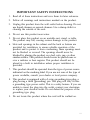
IMPORTANT SAFETY INSTRUCTIONS
1. Read all of these instructions and save them for later reference.
2. Follow all warnings and instructions marked on the product.
3. Unplug this product from the wall outlet before cleaning. Do not
use liquid cleaners or aerosol cleaners. Use a damp cloth for
cleaning the outside of the unit.
4. Do not use this product near water.
5. Do not place this product on an unstable cart, stand, or table.
The product may fall, causing serious damage to the product.
6. Slots and openings in the cabinet and the back or bottom are
provided for ventilation; to ensure reliable operation of the
product and to protect it from overheating, these openings must
not be blocked or covered. The openings should never be
blocked by placing the product on a bed, sofa, rug, or other
similar surface. This product should never be placed near or
over a radiator or heat register. This product should not be
placed in a built in installation unless proper ventilation is
provided.
7. This product should be operated from the type of power source
indicated on the marking label. If you are not sure of the type of
power available, consult your dealer or local power company.
8. This product is equipped with a 3-wire grounding-type plug, a
plug having a third (grounding) pin. This plug will only fit into
a grounding type power outlet. This is a safety feature. If you are
unable to insert the plug into the outlet, contact your electrician
to replace your obsolete outlet. Do not defeat the purpose of the
grounding type plug.
9. Do not locate this product where the cord will be walked on.
iii
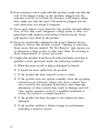
10. If an extension cord is used with this product, make sure that the
total of the ampere ratings on the products plugged into the
extension cord do not exceed the extension cord ampere rating.
Also, make sure that the total of all products plugged into the
wall outlet does not exceed 15 amperes.
11. Never push objects of any kind into this product through cabinet
slots, as they may touch dangerous voltage points or short out
parts that could result in a risk of fire or electric shock. Never
spill liquid of any kind on the product.
12. Except as specifically explained in the User’s Manual, do not
attempt to service this product yourself. Opening or removing
those covers that are marked “Do Not Remove” may expose you
to dangerous voltage points or other risks. Refer all servicing in
those compartments to service personnel.
13. Unplug this product from the wall outlet and refer servicing to
qualified service personnel under the following conditions:
A. When the power cord or plug is damaged or frayed.
B. If liquid has been spilled into the product.
C. If the product has been exposed to rain or water.
D. If the product does not operate normally when the operating
instructions are followed. Adjust only those controls that
are covered by the operating instructions, since improper
adjustment of other controls may result in damage and will
often require extensive work by a qualified technician to
restore the product to normal operation.
E. If the product has been dropped or the cabinet has been
damaged.
F. If the product exhibits a distinct change in performance,
indicating a need for service.
iv
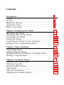
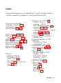
Contents
Introduction
1
Features . . . . . . . . . . . . . . . . . . . . . . . . . . . . . . . . . . . . . . . . . . .
Options . . . . . . . . . . . . . . . . . . . . . . . . . . . . . . . . . . . . . . . . . . .
About This Manual . . . . . . . . . . . . . . . . . . . . . . . . . . . . . . . . .
Application Notes . . . . . . . . . . . . . . . . . . . . . . . . . . . . . . . . . .
Where to Get Help. . . . . . . . . . . . . . . . . . . . . . . . . . . . . . . . . .
1
2
4
6
6
Chapter 1 Setting Up the Printer
1-1
Unpacking the Printer. . . . . . . . . . . . . . . . . . . . . . . . . . . . . . .
Choosing a Place for the Printer . . . . . . . . . . . . . . . . . . . . . .
Assembling the Printer. . . . . . . . . . . . . . . . . . . . . . . . . . . . . .
Testing the Printer. . . . . . . . . . . . . . . . . . . . . . . . . . . . . . . . . .
Connecting the Printer to Your Computer . . . . . . . . . . . . .
Setting Up Your Application Software . . . . . . . . . . . . . . . .
1-2.
1-8
1-10
1-18
1-30
1-34
2-1
Using Single Sheets . . . . . . . . . . . . . . . . . . . . . . . . . . . . . . . . . 2-2
Using Continuous Paper . . . . . . . . . . . . . . . . . . . . . . . . . . . . 2-6
Switching Between Continuous and Single Sheets . . . . . . 2-16
Printing on Special Paper. . . . . . . . . . . . . . . . . . . . . . . . . . . . 2-25
Chapter 2 Paper Handling
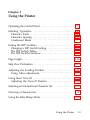
Chapter 3 Using the Printer
Operating the Control Panel . . . . . . . . . . . . . . . . . . . . . . . . .
Selecting Typestyles . . . . . . . . . . . . . . . . . . . . . . . . . . . . . . . .
Setting the DIP Switches. . . . . . . . . . . . . . . . . . . . . . . . . . . . .
Page Length . . . . . . . . . . . . . . . . . . . . . . . . . . . . . . . . . . . . . . .
Skip Over Perforation . . . . . . . . . . . . . . . . . . . . . . . . . . . . . . .
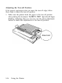
Adjusting the Loading Position. . . . . . . . . . . . . . . . . . . . . . .
3-1
3-2
3-6
3-12
3-18
3-19
3-21
V
Using Short Tear-off . . . . . . . . . . . . . . . . . . . . . . . . . . . . . . . .
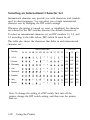
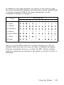
Selecting an International Character Set . . . . . . . . . . . . . . .
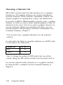
Choosing a Character Set . . . . . . . . . . . . . . . . . . . . . . . . . . .
Using the Data Dump Mode . . . . . . . . . . . . . . . . . . . . . . . . .
3-24
3-28
3-30
3-32
4-1
Enhancing Your Printing . . . . . . . . . . . . . . . . . . . . . . . . . . . . 4-2
Graphics.. . . . . . . . . . . . . . . . . . . . . . . . . . . . . . . . . . . . . . . . . 4-10
User-defined Characters. . . . . . . . . . . . . . . . . . . . . . . . . . . . . 4-22
Chapter 4 Software and Graphics
5-1
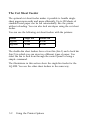
The Cut Sheet Feeder . . . . . . . . . . . . . . . . . . . . . . . . . . . . . . . 5-2
The Pull Tractor . . . . . . . . . . . . . . . . . . . . . . . . . . . . . . . . . . . . 5-28
The Interface Boards . . . . . . . . . . . . . . . . . . . . . . . . . . . . . 5-41
Chapter 5 Using the Printer Options
6-1
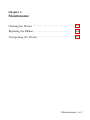
Cleaning the Printer . . . . . . . . . . . . . . . . . . . . . . . . . . . . . . . . 6-2
Replacing the Ribbon . . . . . . . . . . . . . . . . . . . . . . . . . . . . . . . 6-4
Transporting the Printer. . . . . . . . . . . . . . . . . . . . . . . . . . . . . 6-9
Chapter 6 Maintenance
Chapter 7 Troubleshooting
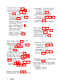
Problems and Solutions . . . . . . . . . . . . . . . . . . . . . . . . . . . . .
Power Supply. . . . . . . . . . . . . . . . . . . . . . . . . . . . . . . . . . . . . .
Printing . . . . . . . . . . . . . . . . . . . . . . . . . . . . . . . . . . . . . . . . . . .
Paper Handling . . . . . . . . . . . . . . . . . . . . . . . . . . . . . . . . . . . .
Options.. . . . . . . . . . . . . . . . . . . . . . . . . . . . . . . . . . . . . . . . . .
7-1
7-2
7-4
7-5
7-16
7-27
8-1
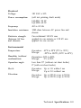
Printer Specifications . . . . . . . . . . . . . . . . . . . . . . . . . . . . . . . 8-2
Interface Specifications . . . . . . . . . . . . . . . . . . . . . . . . . . . . . . 8-10
Option Specifications . . . . . . . . . . . . . . . . . . . . . . . . . . . . . . . 8-15
Initialization . . . . . . . . . . . . . . . . . . . . . . . . . . . . . . . . . . . . . . . 8-17
Chapter 8 Technical Specifications
vi
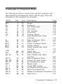
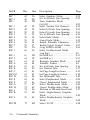
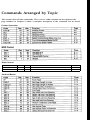
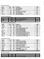
Chapter 9 Command Summary
Using the Command Summary. . . . . . . . . . . . . . . . . . . . . . .
Commands in Numerical Order . . . . . . . . . . . . . . . . . . . . . .
Commands Arranged by Topic. . . . . . . . . . . . . . . . . . . . . . .
9-1
9-2
9-5
9-8
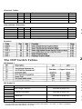
A-1
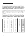
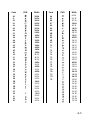
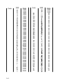
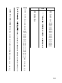
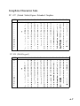
Proportional Width Table . . . . . . . . . . . . . . . . . . . . . . . . . . . A-2
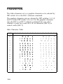
Character Table . . . . . . . . . . . . . . . . . . . . . . . . . . . . . . . . . . . . A-6
Appendix
Glossary
Index
vii
Introduction
The Epson® LQ-850 and LQ-1050 are advanced 24-pin impact dot
matrix printers, combining high performance and reliability with a
wide range of features.
Features
In addition to the high-quality printing and ease of operation you
have come to expect from Epson printers, the LQ-850 and LQ-1050
offer the following features:
•
•
Easy paper handling, featuring automatic single-sheet loading.
Compatibility with the Epson ESC/P commands used by
the LQ-500, LQ-510, LQ-800, LQ-1000, LQ-1500, LQ-2500, and
LQ-2550.
®
•
Fast draft printing of up to 300 characters per second at 10
characters per inch (cpi) in Super Draft mode, and 295
characters per second at 12 cpi or 246 characters per second at
10 cpi in normal draft mode.
•
An improved control panel design that allows direct selection of
many of the printer’s main features including character fonts
and character spacing, as well as a choice of normal or
condensed printing.
•
The SmartPark™ paper handling system that lets you use single
sheets of paper without removing the continuous paper,
eliminates paper waste with short tear-off, and allows easy and
accurate paper alignment.
Nine built-in Letter Quality fonts for producing high-quality
documents:
•
Epson Roman, Epson Sans Serif, Epson Courier,
Epson Prestige, OCR-B, OCR-A, Epson Script,
Epson Orator, Epson Orator-S.
•
A 360 x 360 dot per inch graphics mode.
Introduction 1
•
A micro-adjustment feature that allows you to feed the paper
forward or backward in 1/180-inch increments to finely adjust
the loading and short tear-off positions.
•
An auto-load feature lets you load a single sheet of paper
automatically when not using the optional cut sheet feeder.
•
The Epson Extended Graphics character table, 14 international
character sets, a legal symbol set, and an italic character table.
•
The ability to handle a wide range of paper types, including
envelopes and labels.
Options
A variety of printer options is available for use with your printer.
For detailed information on using these options, see Chapter 5.
To locate or purchase options or supplies, call Epson Accessories,
Inc. at 1800-873-7766.
Single-bin and Double-bin Cut Sheet Feeders
(#7339/#7340/#7346/#7348)
l
The cut sheet feeders make it possible to handle single-sheet
paper and envelopes more easily and more efficiently. Up to
150 sheets of standard bond paper can be automatically fed
into the printer without reloading.
2
Introduction
l
l
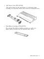
Pull Tractor Unit (#7311/#7312)
This option improves the performance of continuous paper
handling. It is especially useful with continuous multi-part forms.
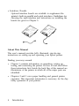
Film Ribbon Cartridge (#7768/#7770)
The optional film ribbon cartridge provides you with even
higher quality printing than the standard fabric ribbon.
Introduction 3
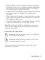
l
Interface Boards
Optional interface boards are available to supplement the
printer’s built-in parallel and serial interfaces. Guidelines for
choosing the right interface and instructions on installing the
boards are given in Chapter 5.
About This Manual
This user’s manual provides fully illustrated, step-by-step
instructions on setting up and operating your Epson printer.
Finding your way around
l
l
4
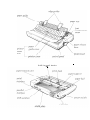
Chapter 1 contains information on unpacking, setting up,
testing, and connecting the printer. Be sure to read and follow
these instructions first. Inside the back flap of this manual are
illustrations of the printer in which all of the major parts are
identified.
Chapters 2 and 3 cover paper handling and general printer
operation. This important information is necessary for the daytoday operation of your printer.
Introduction
•
Chapter 4 shows you how to get the most from your printer. It
includes advice on the use of software commands and graphics,
and creating your own user-defined characters. See Chapter 9
for a useful summary of printer commands.
•
If the printer does not operate properly or the printed results are
not what you expect, see Chapter 7 for troubleshooting
instructions.
•
Other chapters and the appendix contain information on printer
options, general maintenance, and specifications. You will also
find a glossary of printer terms.
•
At the back of this manual is a handy Quick Reference card that
contains the information you are most likely to need.
Note: The LQ-850 and LQ-1050 are basically the same printer
except for their widths. Therefore, the illustrations in this guide
show only the LQ-1050.
Conventions used in this manual
WARNINGS must be followed carefully to avoid damage
to your printer and computer.
CAUTIONS should be followed carefully to ensure that
your printer operates correctly.
Notes contain important information and useful tips on the
operation of your printer.
Introduction 5
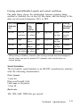
Where to Get Help
A network of authorized Epson dealers and Customer Care
Centers throughout the United States offers customer support and
service for Epson products. Epson America provides product
information and support to its dealers and Customer Care
Centers.
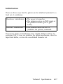
Therefore, we ask that you contact the business where you
purchased your Epson product to request assistance. If the people
there do not have the answer to your question, they can obtain it
through our dealer support program.
Epson is confident that this policy will provide you with the
assistance you need. Call the Epson Consumer Information Center
at 1213-782-2600 for the following:
l
The location of the nearest Epson dealer.
l
The location of the nearest Customer Care Center.
To locate or purchase accessories or supplies, contact your Epson
dealer.
6
Introduction
Chapter 1
Setting Up the Printer
Unpacking the Printer. . . . . . . . . . . . . . . . . . . . . . . . . . . . . . . 1-2
Checking the Parts. . . . . . . . . . . . . . . . . . . . . . . . . . . . . . . . 1-2
Removing the Protective Materials. . . . . . . . . . . . . . . . . . 1-3
Choosing a Place for the Printer . . . . . . . . . . . . . . . . . . . . . .
1-8
Assembling the Printer. . . . . . . . . . . . . . . . . . . . . . . . . . . . . .
Installing the Platen Knob . . . . . . . . . . . . . . . . . . . . . . . . .
Installing the Ribbon Cartridge. . . . . . . . . . . . . . . . . . . . .
Attaching the Paper Guide. . . . . . . . . . . . . . . . . . . . . . . . .
1-10
1-10
1-11
1-15
Testing the Printer. . . . . . . . . . . . . . . . . . . . . . . . . . . . . . . . . .
Plugging in the Printer . . . . . . . . . . . . . . . . . . . . . . . . . . . .
Running the Self Test . . . . . . . . . . . . . . . . . . . . . . . . . . . . .
Solving Any Self Test Problems . . . . . . . . . . . . . . . . . . .
1-18
1-18
1-19
1-27
Connecting the Printer to Your Computer . . . . . . . . . . . . . 1-30
The Parallel Interface . . . . . . . . . . . . . . . . . . . . . . . . . . . . . 1-31
The Serial Interface . . . . . . . . . . . . . . . . . . . . . . . . . . . . . . . 1-32
Setting Up Your Application Software . . . . . . . . . . . . . . . .
Choosing From a Menu . . . . . . . . . . . . . . . . . . . . . . . . . . .
Setting Up the Printer
1-34
1-34
1-1
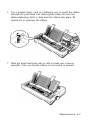
Unpacking the Printer
Checking the Parts
When you unpack the printer, make sure that you have all the parts
shown below and that none have been damaged.
Cross-head screwdriver
1-2
Setting Up the Printer
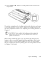
After removing the parts, save the packing materials in case you
ever need to transport your printer.
The ribbon cartridge that comes with the LQ-850 is #7753; #7754
comes with the LQ-1050.
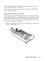
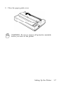
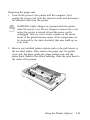
Removing the Protective Materials
The printer is protected during shipping by two locking brackets,
two locking tabs, and a print head protector. These protective items
must be removed before you turn on the printer. After removing
these items, store them with the other packing material in case you
ever need to transport your printer.
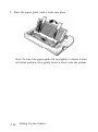
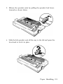
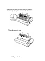
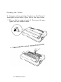
1. Remove the printer cover unit, which includes the printer cover
and the paper guide cover.
Setting Up the Printer
1-3
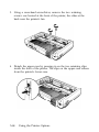
2. Remove any pieces of white packing material you find inside the
printer.
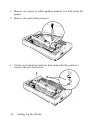
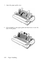
3. Remove the print head protector.
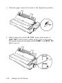
4. Use the cross-head screwdriver that came with the printer to
remove the two red screws.
1-4
Setting Up the Printer
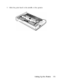
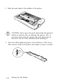
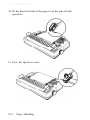
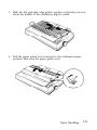
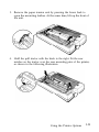
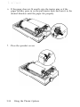
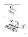
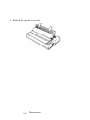
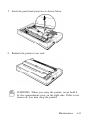
5. Slide the print head to the middle of the printer.
Setting Up the Printer
15
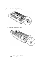
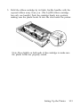
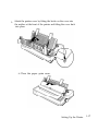
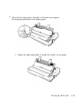
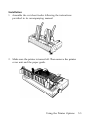
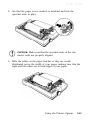
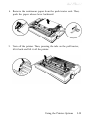
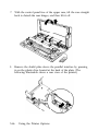
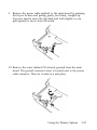
6. Remove the left and right locking tabs.
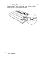
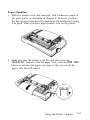
7. Attach the printer cover unit.
1-6
Setting Up the Printer
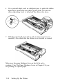
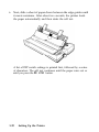
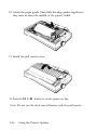
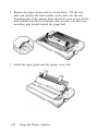
8. Close the paper guide cover.
WARNING: Be sure to remove all protective materials
before you turn on the printer.
Setting Up the Printer
1-7
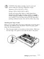
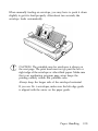
Choosing a Place for the Printer
There are several important things to consider when selecting a
place to set up your printer. Keep the following in mind:
•
Place the printer on a flat, hard, stable surface. A soft surface,
such as a padded counter or carpeted area, will block the
ventilation slots and may cause overheating.
•
Place the printer close enough to the computer for the printer
cable to reach.
•
Leave adequate room around the printer to allow for easy
printer operation and maintenance, and for unrestricted flow of
air around the printer.
•
Use a grounded outlet; do not use an adapter plug.
•
Avoid locations that are subject to direct sunlight, excessive
heat, moisture, or dust.
•
Avoid electrical outlets controlled by wall switches or automatic
timers. Accidental interruption of power can wipe out
information in both your computer’s memory and in your
printer's memory.
•
Avoid using outlets that share a circuit with large motors or
electrical appliances; this could cause fluctuations in line
voltage.
•
Keep the entire computer system away from potential sources of
electromagnetic interference such as loudspeakers or the base
units of cordless telephones.
1-8
Setting Up the Printer
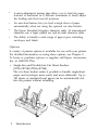
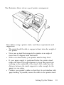
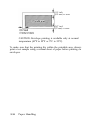
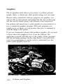
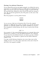
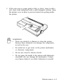
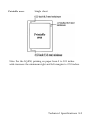
The illustration below shows a good printer arrangement.
Note: Before using a printer stand, read these requirements and
suggestions.
l
l
l
l
l
The stand should be able to support at least twice the weight of
the printer.
Never use a stand that supports the printer at an angle of
more than 15 degrees from horizontal.
With a cut sheet feeder, your printer must be kept level.
If your paper supply is positioned below the printer stand,
make sure there is enough clearance to keep the paper from
catching on the underside of the stand. Also, make sure the
distance between the stand supports is wide enough for the
paper you are using.
Position your printer’s cables so that they do not interfere with
paper feeding. If possible, secure the cables to the printer stand.
Setting Up the Printer
1-9
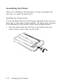
Assembling the Printer
After you’ve decided on the best place to set up your printer, the
next step is to install the platen knob.
Installing the Platen Knob
You use the platen knob to feed the paper manually in the event of a
paper jam or other paper feeding problem. The platen knob is packed
in an indentation in the printer’s white foam packing material.
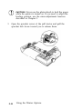
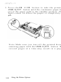
1. Insert the platen knob into the hole on the printer’s side and
rotate it slowly until it slips onto the shaft.
1-10
Setting Up the Printer
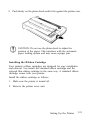
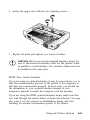
2. Push firmly on the platen knob until it fits against the printer case.
CAUTION: Do not use the platen knob to adjust the
position of the paper. This interferes with the automatic
paper loading system and may cause a paper jam.
Installing the Ribbon Cartridge
Your printer’s ribbon cartridges are designed for easy installation
and removal. You install. the standard ribbon cartridge and the
optional film ribbon cartridge in the same way. A standard ribbon
cartridge comes with your printer.
Install the ribbon cartridge as follows:
1. Make sure the printer is turned off.
2. Remove the printer cover unit.
Setting Up the Printer
1-11
3. Slide the print head to the middle of the printer.
CAUTION: Never move the print head while the printer is
turned on because this can damage the printer. Also, if
you have been using the printer, the print head may be
hot; let it cool for a few minutes before touching it.
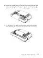
4. Turn the ribbon-tightening knob in the direction of the arrow.
This removes slack in the ribbon and makes it easier to install.
1-12
Setting Up the Printer
5. Hold the ribbon cartridge by its black, fin-like handles with the
exposed ribbon away from you. (The LQ-850 ribbon cartridge
has only one handle.) Push the cartridge firmly into position,
making sure the plastic hooks fit into the slots inside the printer.
Note: Press lightly on both ends of the cartridge to make sure
the plastic hooks are properly seated.
Setting Up the Printer
1-13
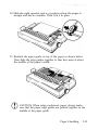
6. Use a pointed object, such as a ballpoint pen, to guide the ribbon
between the print head and ribbon guide while you turn the
ribbon-tightening knob to help feed the ribbon into place.
7. Slide the print head from side to side to make sure it moves
smoothly. Also check that the ribbon is not twisted or creased.
Make sure the paper thickness lever on the left is set to
position 2. See The Paper Thickness Lever in Chapter 2 if you
are printing on special paper.
1-14
Setting Up the Printer
CAUTION: Film ribbon cartridges must be used and
stored within the following temperature ranges:
Operation: 41°F to 95°F (5°C to 35°C)
Storage: -22°F to 104°F (-30°C to 40°C)
Storing and using a film ribbon at high temperatures
shortens the ribbon’s life expectancy, which is normally
200,000 characters (#7768) or 300,000 characters (#7770). If
you continue to use the ribbon beyond its life expectancy,
printing suddenly becomes faint and the ribbon may snap.
Attaching the Paper Guide
When you use single sheets, the paper guide helps to feed the paper
smoothly and efficiently into the printer. Attach the paper guide
using the following procedure.
1. Place the paper guide on the printer as shown below. Make sure
the back edge of the guide is even with the back of the printer.
Setting Up the Printer
1-15
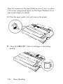
2. Raise the paper guide until it locks into place.
Note: To lower the paper guide, lift up slightly to release it from
its locked position; then gently lower it down onto the printer.
1-16
Setting Up the Printer
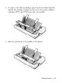
3. Attach the printer cover by fitting the hooks on the cover into
the notches at the front of the printer and tilting the cover back
into place.
4. Close the paper guide cover.
Setting Up the Printer
1-17
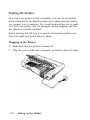
Testing the Printer
Now that your printer is fully assembled, you can use its built-in
self test function to see that the printer is working correctly before
you connect it to a computer. You should perform this test to make
sure that your printer was not damaged during shipping and that
the ribbon is correctly installed.
Before running the self test, you need to connect the printer to an
electrical outlet and load a sheet of paper.
Plugging in the Printer
1. Make sure that the printer is turned off.
2. Plug the power cable into a properly grounded electrical outlet.
1-18
Setting Up the Printer
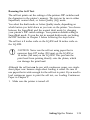
Running the Self Test
The self test prints out the settings of the printers DIP switches and
the characters in the printer’s memory. The test can be run in either
SuperDraft, normal draft, or Letter Quality (LQ) mode.
You select the draft mode or Letter Quality mode, depending on
which button you hold down as you turn on the printer. You choose
between the SuperDraft and the normal draft mode by changing
your printer’s DIP switch settings. Your printers default setting is
SuperDraft mode. To run the test in normal draft mode, see Setting
the DIP Switches in Chapter 3 before following the steps below.
The self test is 8 inches wide on the LQ-850 and 14 inches wide on
the LQ-1050.
CAUTION: Never run the self test using paper that is
narrower than 8.27 inches (210 mm) on the LQ-850 or
14 inches (360 mm) on the LQ-1050. This prevents the
print head from printing directly onto the platen, which
can damage the print head.
Although the self test can be run with continuous paper, use singlesheet paper now because single-sheet loading is easier. Be sure to
use paper that is wide enough for the self test to print. If you need to
load continuous paper to print the self test, see Loading Continuous
Paper in Chapter 3.
1. Make sure the printer is turned off.
Setting Up the Printer
1-19
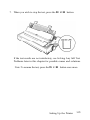
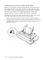
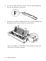
2. Push the paper release lever back to the single-sheet position.
3. While holding down the LINE FEED button (draft mode) or
FORM FEED button (Letter Quality mode), turn on the printer.
The printer beeps several times and the POWER and PAPER OUT
lights come on.
1-20
Setting Up the Printer
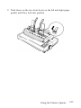
4. Move the left edge guide to the right or left until it rests against
the triangular guide mark on the paper guide
5. Adjust the right edge guide to match the width of your paper.
Setting Up the Printer
1-21
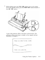
6. Next, slide a sheet of paper down between the edge guides until
it meets resistance. After about two seconds, the printer loads
the paper automatically and then starts the self test.
A list of DIP switch settings is printed first, followed by a series
of characters. The self test continues until the paper runs out or
until you press the ON LINE button.
1-22
Setting Up the Printer
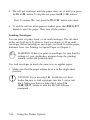
7. When you wish to stop the test, press the ON LINE button.
If the test results are not satisfactory, see Solving Any Self Test
Problems later in this chapter for possible causes and solutions.
Note: To resume the test, press the ON LINE button once more.
Setting Up the Printer
1-23
8. To end the self test, press the FORM FEED button to eject any
paper that is still loaded. Then turn off the printer.
WARNING: After turning the power off, always wait at
least five seconds before turning it back on. Turning the
power on and off rapidly can damage the printer.
1-24
Setting Up the Printer
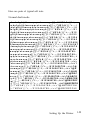
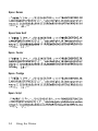
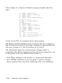
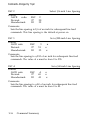
Here are parts of typical self tests.
Normal draft mode
abcdefghijklmnopqrstuvwxyz{¦}~!”#$%&’()*+,-.
bcdefghijklmnopqrstuvwxyz{¦}~!”#$%&’()*+,-./
cdefghijklmnopqrstuvwxyz{¦}~!”#$%&’()*+,-./0
defghijklmnopqrstuvwxyz{¦}~!”#$%&’()*+,-./01
efghijklmnopqrstuvwxyz{¦}~!”#$%&’()*+,-./012
fghijklmnopqrstuvwxyz{¦}~!”#$%&’()*+,-./0123
ghijklmnopqrstuvwxyz{¦}~!”#$%&’()*+,-./01234
hijklmnopqrstuvwxyz{¦}~!”#$%&’()*+,-./012345
i j k l m n o p q r s t u v w x y z { ¦ } ~! ” # $ % & ’ ( ) * + , - . / 0 1 2 3 4 5 6
jklmnopqrstuvwxyz{¦}~ ! ” # $ % & ’ ( ) * + , - . / 0 1 2 3 4 5 6 7
k l m n o p q r s t u v w x y z { ¦ } ~! ” # $ % & ’ ( ) * + , - . / 0 1 2 3 4 5 6 7 8
lmnopqrstuvwxyz{¦}~!”#$%&’()*+,-./0123456789
mnopqrstuvwxyz{¦}~!”#$%&’()*+,-./0123456789:
nopqrstuvwxyz{¦}~!”#$%&’()*+,-./0123456789:;
opqrstuvwxyz{¦}~!”#$%&’()*+,-./0123456789:;<
pqrstuvwxyz{¦}~!”#$%&’()*+,-./0123456789:;<=
qrstuvwxyz{¦}~!”#$%&’()*+,-./0123456789:;<=>
rstuvwxyz{¦}~!”#$%&’()*+,-./0123456789:;<=>?
s t u v w x y z { ¦ } ~ !” # $ % & ’ ( ) * + , - . / 0 1 2 3 4 5 6 7 8 9 : ; < = > ? @
tuvwxyz{¦}~!”#$%&’()*+,-./0123456789:;<=>?@A
uvwxyz{¦}~!”#$%&’()*+,-./0123456789:;<=>?@AB
vwxyz{¦}~!”#$%&’()*+,-./0123456789:;<=>?@ABC
w x y z { ¦ } ~ !” # $ % & ’ ( ) * + , - . / 0 1 2 3 4 5 6 7 8 9 : ; < = > ? @ A B C D
x y z { ¦ } ~ ! ” # $ % & ’ ( ) * + , - ./0123456789:;<=>?@ABCDE
y z { ¦ } ~ ! ” # $ % & ’ ( ) * + - , - ./0123456789:;<=>?@ABCDEF
z { ¦ } ~ ! ” # $ % & ’ ( ) * + , - . / 0 1 2 3 4 5 6 7 8 9 : ;<=>?@ABCDEFG
{¦}~!”#$%&’()*+,-./0123456789:;<=>?@ABCDEFGH
¦}~!”#$%&’()*+,-./0123456789:;<=>?@ABCDEFGHI
Setting Up the Printer
1-25
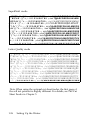
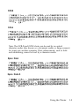
SuperDraft mode
!”#$%,&.’()*+,-./0123456789:;<=>?@ABCDEFGHIJKLM
! " # $ % & ’ ( ) * + , - . / 0 1 2 3 4 5 6 7 8 9 :;<=>?@ARCDEFGHIJKLMN
" # $ % & ’ ( ) * + , - . / 0 1 2 3 4 5 6 7 8 9 : ;<=>?@ABCDEFGHIJKLMNO
# $ % & ’ ( ) * + , - . / 0 1 2 3 4 5 6 7 8 9 :;<=>?@ABCDEFGHIJKLMNOP
$ % & ’ ( ) * + , - . / 0 1 2 3 4 5 6 7 8 9 : ; <=>?@ABCDEFGHIJKLMNOPQ
% & ’ ( ) * + , - . / 0 1 2 3 4 5 6 7 8 9 : ; <=>?@ABCDEFGHIJKLMNOPQR
& ’ ( ) * + , - . / 0 1 2 3 4 5 6 7 8 9 : ; <=>?@ABCDEFGHIJKLMNOPQRS
’ ( ) * + , - . / 0 1 2 3 4 5 6 7 8 9 :;<=>?@ABCDEFGHIJKLMNOPQRST
( ) *+,-. / 0 1 2 3 4 5 6 7 8 9 : ; <=>?@ABCDEFGHIJKLMNOPQRSTU
) * + , - . / 0 1 2 3 4 5 6 7 8 9 : ; <=>?@ABCDEFGHIJKLMNOPQRSTUV
* + , - . / 0 1 2 3 4 5 6 7 8 9 : ;<=>?@ABCDEFGHIJKLMNOPQRSTUVW
+ , - . / 0 1 2 3 4 5 6 7 8 9 - -<=>?ABCDEFGHIJKLMNOPQRSTUVWX
Letter Quality mode
!"#$%&'()*+,-./0123456789:;<=>?@ABCDEFGHIJKLM
!"#$%&'()*+,-./0123456789 :;<=>?@ABCDEFGHIJKLMN
"#$%&'()*+, -./0123456789: ;<=>?@ABCDEFGHIJKLMNO
#$%&'()*+,-./0123456789:;(=>?@ABCDEFGHIJKLMNOP
$%&'()*+,- ./0123456789:; <=>?@ABCDEFGHIJKLMNOPQ
%&'()*+,- ./0123456789:; <=>?@ABCDEFGHIJKLMNOPQR
&'()*+,- ./0123456789:; <=>?@ABCDEFGHIJKLMNOPQRS
'()*+,- ./0123456789: ;<=>?@ABCDEFGHIJKLMNOPQRST
()*+,- ./0123456789:; <=>?@ABCDEFGHIJKLMNOPQRSTU
)*+,-. /0123456789:; <=>?@ABCDEFGHIJKLMNOPQRSTUV
*+,-. /0123456789: ;<=>?@ABCDEFGHIJKLMNOPQRSTUVW
+.-. / 0 1 2 3 4 5 6 7 8 9 : ; < = > ? @ A B C D E F G H I J K L M N O P Q R S T U V W X
Note: When using the optional cut sheet feeder, the first page of
the self test printout is slightly different. For details, see The Cut
Sheet Feeder in Chapter 5.
1-26
Setting Up the Printer
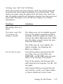
Solving Any Self Test Problems
If the self test does not print properly, check the control panel and
the print head area. If paper is jammed, turn off the printer. Then
remove the paper using the platen knob and load a new sheet. See
that all packing material and shipping restraints have been removed
from inside the printer. (You can also see Chapter 7 for further
information.)
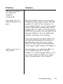
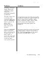
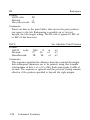
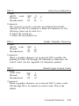
Problem
Solution
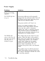
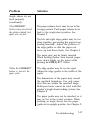
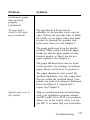
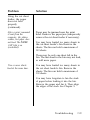
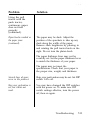
The printer does not
print.
The printer sounds like
it is printing, but
nothing is printed.
The ribbon may not be installed properly.
Turn off the printer, reinstall the ribbon
cartridge, and then tighten the ribbon by
turning the ribbon-tightening knob. Make
sure the ribbon passes between the print
head and ribbon guide.
The ribbon may be worn. Replace the
ribbon cartridge. See Replacing the
Ribbon in Chapter 6.
The test did not print.
Turn off the printer and repeat the self
test. Make sure you hold down the
FORM FEED or LINE FEED button the entire
time you are turning on the printer.
Turn off the printer and disconnect the
cable from the host computer. Try the self
test again.
If the printer still does not print the self
test correctly, contact your Epson dealer
or Epson authorized service center.
Setting Up the Printer
1-27
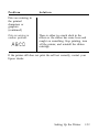
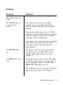
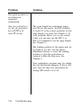
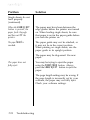
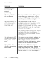
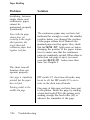
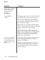
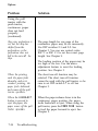
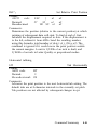
Problem
Solution
The print is faint or
uneven.
Printed characters
have part missing at
the bottom as shown
here.
ABCD
The printout is faint.
The ribbon cartridge may not be properly
installed. Remove the ribbon cartridge
and reinstall it; make sure the cartridge
hooks are inserted securely into the
printer.
The ribbon may be worn out. A worn
ribbon can damage the print head and
should be replaced. Install a new ribbon
cartridge as soon as possible. See
Replacing the Ribbon in Chapter 6.
The paper thickness lever may not be set
correctly for the paper you are using. Set
the paper thickness lever to match the
thickness of your paper. See The Paper
Thickness Lever in Chapter 2.
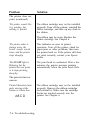
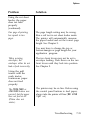
Dots are missing in
the printed
characters or
graphics.
A line of dots is missing
in the printout.
1-28
The print head is damaged. Stop printing
and contact your Epson dealer to have the
print head replaced.
Setting Up the Printer
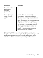
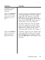
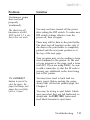
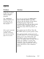
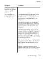
Problem
Solution
Dots are missing in
the printed
characters or
graphics.
(continued)
Dots are missing in
random positions.
There is either too much slack in the
ribbon or the ribbon has come loose and
caught on something. Stop printing, turn
off the printer, and reinstall the ribbon
cartridge.
If the printer still does not print the self test correctly, contact your
Epson dealer.
Setting Up the Printer
1-29
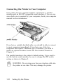
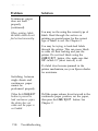
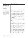
Connecting the Printer to Your Computer
Your printer has two separate interface connections: a parallel
interface and an RS-232C compatible serial interface. If you are not
sure which one is required by your computer, check your computer
manual for this information.
If you have a suitable shielded cable, you should be able to connect
to most computers immediately. If you have one of the few
computers that require a different type of interface, you need to
install an optional interface board. See The Interface Boards in
Chapter 5.
The parallel interface is the printer’s default setting. If you need to
use the built-in serial interface, be sure to change the DIP switch
setting as shown in Chapter 3.
WARNING: Do not plug more than one interface cable into
the printer at one time. This may damage the printer.
1-30
Setting Up the Printer
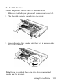
The Parallel Interface
Connect the parallel interface cable as described below:
1. Make sure that both your printer and computer are turned off.
2. Plug the cable connector securely into the printer.
3. Squeeze the wire clips together until they lock in place on either
side of the connector.
Note: If you do not lock these clips into place, your printed
results may be incorrect.
Setting Up the Printer
1-31
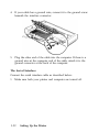
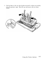
4. If your cable has a ground wire, connect it to the ground screw
beneath the interface connector.
5. Plug the other end of the cable into the computer. If there is a
ground wire at the computer end of the cable, attach it to the
ground connector at the back of the computer.
The Serial Interface
Connect the serial interface cable as described below:
1. Make sure both your printer and computer are turned off.
1-32
Setting Up the Printer
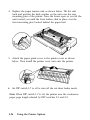
2. Plug the connector securely into the printer.
WARNING: Do not plug more than one interface cable into
the printer at once. This may damage the printer.
3. Plug the other end of the cable into the computer.
Setting Up the Printer
1-33
Setting Up Your Application Software
Now that you have set up and tested the printer, you should make
sure that it works with your application programs.
Most application programs let you specify the type of printer you
are using so that the program can take full advantage of the
printer’s features. Many of these programs provide an installation or
setup menu that presents a list of printers to choose from.
If your application program has a printer selection menu, use the
instructions below.
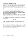
Choosing From a Menu
Because the family of Epson printers shares a great many
commands, you can use an application program even if it does not
list the LQ-850 or LQ-1050 on its printer selection menu. If the
printer is not listed, choose one of the following printers. They are
listed in order of preference.
LQ-800 (LQ-1000)
LQ-510/LQ-500
LQ-1500
If none of these printers is listed, select the first one available on the
following list: LQ, EX, FX, LX, RX, MX, Epson printer, Standard
printer, Draft printer.
To use all of the features of the printer, however, it is best to use a
program with the LQ-850 or LQ-1050 on its menu. If your program
does not list the printer, contact the software manufacturer to see if
an update is available that supports your model.
1-34
Setting Up the Printer
Chapter 2
Paper Handling
Using Single Sheets . . . . . . . . . . . . . . . . . . . . . . . . . . . . . . . . . 2-2
Loading Paper . . . . . . . . . . . . . . . . . . . . . . . . . . . . . . . . . . . 2-2
Reloading During Printing . . . . . . . . . . . . . . . . . . . . . . . . 2-5
Using Continuous Paper . . . . . . . . . . . . . . . . . . . . . . . . . . . . 2-6
Positioning Your Continuous Paper Supply. . . . . . . . . . 2-6
Loading Continuous Paper . . . . . . . . . . . . . . . . . . . . . . . . 2-7
Switching Between Continuous and Single Sheets . . . . . . 2-16
Switching to Single Sheets . . . . . . . . . . . . . . . . . . . . . . . . . 2-16
Switching Back to Continuous Paper. . . . . . . . . . . . . . . . 2-21
Printing on Special Paper. . . . . . . . . . . . . . . . . . . . . . . . . . . .
The Paper Thickness Lever . . . . . . . . . . . . . . . . . . . . . . . .
Multi-part Forms . . . . . . . . . . . . . . . . . . . . . . . . . . . . . . . . .
Labels . . . . . . . . . . . . . . . . . . . . . . . . . . . . . . . . . . . . . . . . . .
Envelopes . . . . . . . . . . . . . . . . . . . . . . . . . . . . . . . . . . . . . . .
2-25
2-25
2-29
2-30
2-32
Paper Handling 2-1
Using Single Sheets
Your printer can accommodate single sheets up to a maximum
width of 10.1 inches (257 mm) on the LQ-850 and 14.3 inches
(364 mm) on the LQ-1050.
If you do most of your printing on single sheets, you may find it
more convenient to install the optional cut sheet feeder. This option
automatically inserts a new sheet and can hold up to 150 pages. For
more details, see Chapter 5.
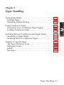
Loading Paper
1. Make sure the printer is turned off.
2. Push the paper release lever back to the single-sheet position.
This position is marked by the icon shown below.
Note: For normal use, the paper thickness lever is set to position
2. See The Paper Thickness Lever later in this chapter if you are
printing on special paper.
2-2
Paper Handling
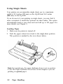
3. Turn on the printer. The POWER and PAPER OUT lights come on.
Note: Do not insert paper in the printer before turning on the printer.
4. Move the left edge guide until it rests against the guide mark.
(You may want to change this position later, depending on the
margin settings of your application program.)
Paper Handling 2-3
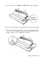
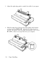
5. Adjust the right edge guide to match the width of your paper.
6. Slide the paper down between the edge guides until it meets
resistance and the PAPER OUT light goes off. After about two
seconds, the printer loads the paper automatically, and is set to
ON LINE so that it can accept data from your computer.
2-4
Paper Handling
WARNING: Never advance the paper using the platen
knob except in the case of a paper jam or other paper feed
problem. Using the platen knob while the printer is on
may damage the printer and affect the loading and short
tear-off positions.
Note: If the platen turns without loading the paper, press the
ON LINE button to take the printer off line and completely remove
the paper. Then re-insert the paper more firmly.
If you need to adjust the position of the paper after it is loaded, use
the micro-adjustment feature described in Adjusting the Loading
Position in Chapter 3.
To eject the paper, press the ON LINE button to take the printer off
line; then press the LOAD/EJECT button.
You are now ready to begin printing.
Reloading During Printing
When you print a document of more than one page using singlesheet paper, the printer stops printing when it reaches the bottom of
the page. When this happens, the ON LINE light either goes off
automatically or remains on, depending on your application
program software. If the ON LINE light remains on, the first thing you
do is press the ON LINE button to take the printer off line.
Once the ON LINE light is off, remove the sheet that has just been
printed (if necessary, press the FORM FEED button to eject the page).
Then load a new sheet to start printing the next page and follow any
additional prompts from your software.
Paper Handling 2-5
Using Continuous Paper
The tractor built into your printer is remarkably easy to load and
operate. Its low-profile design takes up little space and can handle
paper up to 10.0 inches or 254 mm wide on the LQ-850 and up to
16.0 inches or 406 mm wide on the LQ-1050.
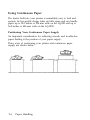
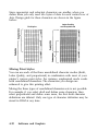
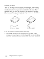
Positioning Your Continuous Paper Supply
An important consideration for achieving smooth and trouble-free
paper feeding is the position of your paper supply.
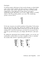
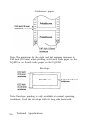
Three ways of positioning your printer and continuous paper
supply are shown below.
2-6
Paper Handling
Be sure to align the paper supply with the paper loaded in the
tractor so that the paper feeds smoothly into the printer.
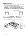
Loading Continuous Paper
1. Be sure that the printer is turned off.
2. Pull the paper release lever forward to the continuous paper
position. This position is marked by the icon shown in the
illustration below.
Paper Handling 2-7
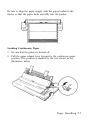
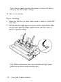
3. Open the paper guide cover and remove the paper guide.
4. Attach the paper rest.
2-8
Paper Handling
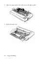
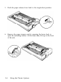
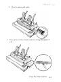
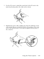
5. Release the sprocket units by pulling the sprocket lock levers
forward as shown below.
6. Slide the left sprocket unit all the way to the left and press the
lever back to lock it in place.
Paper Handling 2-9
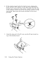
Note: The first printable column position is indicated by the mark
shown in the illustration below.
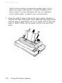
7. Slide the right sprocket unit so that it roughly matches the width
of your paper, but do not lock it.
2-10
Paper Handling
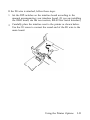
8. Move the paper support midway between the two sprocket
units.
9. Open both sprocket covers.
CAUTION: Make sure that the first sheet of paper has a
clean, straight edge before inserting it into the printer.
Paper Handling
2-11
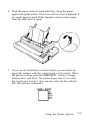
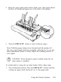
10. Fit the first four holes in the paper over the pins of both
sprockets.
11. Close the sprocket covers.
2-12
Paper Handling
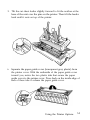
12. Slide the right sprocket unit to a position where the paper is
straight and has no wrinkles. Then lock it in place.
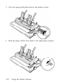
13. Reattach the paper guide on top of the paper as shown below.
Then slide the edge guides together so that they meet at about
the middle of the paper’s width.
CAUTION: When using continuous paper, always make
sure that the paper edge guides are pushed together in the
middle of the paper guide.
Paper Handling
2-13
Note: For normal use, the paper thickness lever is set to position
2. If you are using special paper, see The Paper Thickness Lever
later in this chapter for details.
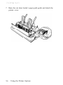
14. Close the paper guide cover and turn on the printer.
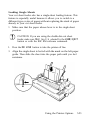
15. Press the LOAD/EJECT button to feed paper to the loading
position.
2-14
Paper Handling
16. Press the ON LINE button to set the printer on line so that it can
accept data.
The printer remembers the loading position and advances each page
to the same position. If you need to adjust the loading position, use
the micro-adjustment feature. See Adjusting the Loading Position in
Chapter 3.
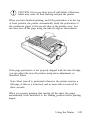
CAUTION: Never adjust the loading position using the
platen knob and never turn the platen knob while the
printer is turned on.
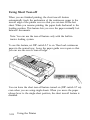
When using continuous paper, you can choose the short tear-off
feature to give you added paper handling capabilities. This feature
makes it easier to detach printed pages and saves the blank pages
that are usually lost between printing jobs. See Using Short Tear-off
in Chapter 3 for details.
Paper Handling
2-15
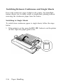
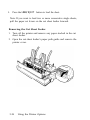
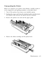
Switching Between Continuous and Single Sheets
Even with continuous paper loaded in the printer, the SmartPark
feature allows you to easily switch to single-sheet printing without
removing the continuous paper from the tractor.
Switching to Single Sheets
To switch from continuous paper to single sheets, follow the steps
below.
1. If the printer is on line, press the ON LINE button to set the printer
off line. Open the paper guide cover.
2-16
Paper Handling
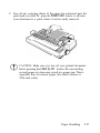
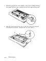
2. Tear off any outgoing sheets. If the paper has advanced past the
print head, you need to press the FORM FEED button to advance
your document to a point where it can be easily removed.
CAUTION: Make sure you tear off your printed document
before pressing the LOAD/EJECT button. Reverse-feeding
several pages at a time may result in a paper jam. This is
especially true for narrow paper (less than 6 inches or
152.4 mm wide).
Paper Handling
2-17
3. Press the LOAD/EJECT button to feed the continuous paper
backward out of the printer and into the standby position. The
paper is still attached to the tractor but no longer in the paper
path. The PAPER OUT light comes on when the paper is
completely out of the paper path.
CAUTION: Pressing the LOAD/EJECT button once may not
feed the paper far back enough to reach the standby
position. If the PAPER OUT light does not come on, press
the LOAD/EJECT button again. With normal-width
continuous paper, you can press the LOAD/EJECT button up
to three times. If, however, you are using narrow paper
(between 4 and 6 inches or 101.6 and 152.4 mm) you can
press the LOAD/EJECT button only once. Also, do not use
this button to eject labels.
WARNING: Never feed labels backward through the
printer. Labels can easily come off the backing sheet and
jam the printer.
2-18
Paper Handling
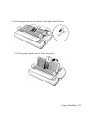
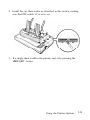
4. Push the paper release lever back to the Single-Sheet Position
5. Lift the paper guide until it locks into place.
Paper Handling 2-19
6. Move the left edge guide until it rests against the guide mark.
Adjust the right edge guide to match the width of your paper.
7. Close the paper guide cover.
2-20 Paper Handling
8. Slide a sheet of paper down between the edge guides until it
meets resistance and the PAPER OUT light goes off. After about
two seconds, the printer loads the paper automatically and sets
itself ON LINE.
Switching Back to Continuous Paper
It is also easy to switch back to printing with continuous paper.
Before switching to continuous paper, make sure that the single
sheet is ejected and the printer is off line.
Paper Handling
2-21
1. Open the paper guide cover.
2. Lift up slightly on the paper guide and then lower it onto the
back of the printer.
2-22
Paper Handling
3. Slide the left and right edge guides together so that they meet at
about the middle of the continuous paper's width.
4. Pull the paper release lever forward to the continuous paper
position, then close the paper guide cover.
Paper Handling
2-23
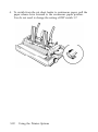
5. Press the LOAD/EJECT button to feed the continuous paper to the
loading position. Then, press the ON LINE button to set the
printer on line so that it can accept data.
2-24
Paper Handling
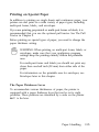
Printing on Special Paper
In addition to printing on single sheets and continuous paper, your
printer can also print on a wide variety of paper types, including
multi-part forms, labels,, and envelopes.
If you are printing preprinted or multi-part forms or labels, it is
recommended that you use the optional pull tractor. See The Pull
Tractor in Chapter 5.
Before printing on special types of paper, you need to change the
paper thickness setting.
WARNING: When printing on multi-part forms, labels, or
envelopes, make sure that your application program
settings keep the printing entirely within the printable
area.
For multi-part forms and labels you should not print any
closer than one-half inch (38 mm) from either side of the
paper.
For information on the printable area for envelopes, see
Envelopes later in this chapter.
The Paper Thickness Lever
To accommodate various thicknesses of paper, the printer is
equipped with a paper thickness lever that can be set to eight
positions. These positions are identified by a scale on the printer
next to the lever.
Paper Handling
2-25
Note: For normal use, set the paper thickness lever to position 2
on the scale.
If you have installed the optional film ribbon cartridge, and you
want to use the single sheets or continuous paper, set the paper
thickness lever to position 1.
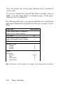
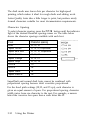
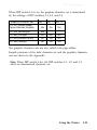
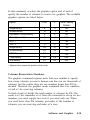
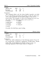
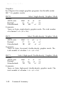
The following table gives you general guidelines for selecting the
right paper thickness lever position for the type of paper you are
using:
Paper type
Paper (single sheets or continuous
paper with film ribbon installed)
Thin paper
Lever position
1
2 or 1
Paper (single sheets or continuous
paper with standard ribbon installed)
2
24 lb paper (single sheets)
3
Multi-part forms
2-sheet
3-sheet
4-sheet
3
4
5
Labels
4
Envelopes
Air mail
Plain
Bond (20 lb.)
Bond (24 lb.)
4 or 5
6
6
7
Note: If the lever is set to position 4 or higher, the printing speed is reduced.
2-26
Paper Handling
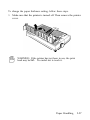
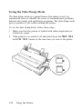
To change the paper thickness setting, follow these steps.
1. Make sure that the printer is turned off. Then remove the printer
cover.
WARNING: If the printer has just been in use, the print
head may be hot. Be careful not to touch it.
Paper Handling
2-27
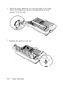
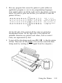
2. Select the paper thickness you want according to the table
below. For normal use, the lever should always be set to
position 2 on the scale.
3. Reattach the printer cover unit.
2-28
Paper Handling
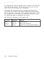
To help you check the position of the paper thickness lever, the
orange MULTI-PART light on the control panel comes on if the
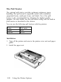
lever is set to position 4 or higher.
WARNING: Always return the lever to position 2 when
you go back to printing on ordinary paper. Continuous
printing with the lever set at a position higher than 2 can
shorten the life of the print head.
Printing past the edge of envelopes, multi-part forms,
labels, or thicker-than-normal paper can damage the print
head.
Multi-part Forms
With the built-in tractor unit, your printer can print on continuous
multi-part forms. You can use multi-part forms that have up to four
parts including the original. Make sure you set the paper thickness
lever to the proper position.
Except for the paper thickness lever setting, you load multi-part
paper the same way as continuous paper. For details, see Loading
Continuous Paper in this chapter. Also see Adjusting the Loading
Position and Page Length in Chapter 3.
Paper Handling
2-29
When you set the paper thickness lever to position 4 or above, the
MULTI-PART light comes on and the printer reduces its printing
speed.
CAUTION: Do not use multi-part forms with the singlesheet feeding system or the optional cut sheet feeder.
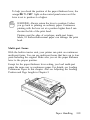
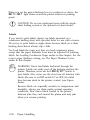
Labels
If you need to print labels, always use labels mounted on a
continuous backing sheet with sprocket holes for use with a tractor.
Do not try to print labels as single sheets because labels on a shiny
backing sheet almost always slip a little.
You load labels the same way that you load continuous paper
except that the paper thickness lever must be adjusted for printing
labels. See Loading Continuous Paper earlier in this chapter. For the
correct paper thickness setting, see The Paper Thickness Lever
earlier in this chapter.
WARNING: Never feed labels backward through the
printer. Labels can easily peel off the backing and jam the
printer. Therefore, never use the LOAD/EJECT button to
eject labels. Also, never use the short tear-off function with
labels. (Be sure to set DIP switch 2-7 to OFF.) If a label
does become stuck in the printer, contact your Epson
dealer.
Because labels are especially sensitive to temperature and
humidity, always use them under normal operating
conditions. Don’t leave labels loaded in the printer
between jobs; they curl around the platen and may jam
when you resume printing.
2-30
Paper Handling
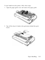
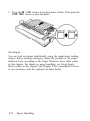
To eject labels from the printer, follow these steps:
1. Open the paper guide cover and remove the paper guide.
2. Tear off the sheet of Labels at the perforation behind the push
tractor.
Paper Handling
2-31
3. Press the ON LINE button to set the printer off line. Then press the
FORM FEED button to eject the labels.
Envelopes
You can feed envelopes individually using the single-sheet loading
feature. Before loading envelopes, adjust the position of the paper
thickness lever according to the Paper Thickness Lever table earlier
in this chapter. For details on paper handling, see Using Single
Sheets earlier in this chapter. See Chapter 5 for a description of how
to use envelopes with the optional cut sheet feeder.
2-32
Paper Handling
When manually feeding an envelope, you may have to push it down
slightly to get it to feed properly. After about two seconds, the
envelope loads automatically.
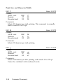
CAUTION: The printable area for envelopes is shown on
the next page. The print head must not go past the left or
right edge of the envelope or other thick paper. Make sure
that your application program page setup keeps the
printing entirely within this printable area.
Always keep the longer side of the envelope horizontal.
If you use No. 6 envelopes, make sure the left edge guide
is aligned with the arrow on the paper guide.
Paper Handling
2-33
0.33 inch
(8.5 mm) or more
0.87 inch
(22 mm) or more
CAUTION: Envelope printing is available only at normal
temperature (41°F to 95°F or 5°C to 35°C).
To make sure that the printing fits within the printable area, always
print a test sample using a normal sheet of paper before printing on
envelopes.
2-34
Paper Handling
Chapter 3
Using the Printer
Operating the Control Panel . . . . . . . . . . . . . . . . . . . . . . . . .
3-2
Selecting Typestyles . . . . . . . . . . . . . . . . . . . . . . . . . . . . . .
Character Fonts . . . . . . . . . . . . . . . . . . . . . . . . . . . . . . . . . .
Character Spacing . . . . . . . . . . . . . . . . . . . . . . . . . . . . . . . .
Condensed Mode . . . . . . . . . . . . . . . . . . . . . . . . . . . . . . . .
3-6
3-6
3-10
3-11
Setting the DIP Switches. . . . . . . . . . . . . . . . . . . . . . . . . . . . .
Changing a DIP Switch Setting . . . . . . . . . . . . . . . . . . . . .
The DIP Switch Tables . . . . . . . . . . . . . . . . . . . . . . . . . . . .
The DIP Switch Functions . . . . . . . . . . . . . . . . . . . . . . . . .
3-12
3-12
3-13
3-16
Page Length . . . . . . . . . . . . . . . . . . . . . . . . . . . . . . . . . . . . . . .
3-18
Skip Over Perforation. . . . . . . . . . . . . . . . . . . . . . . . . . . . . . . 3-19
Adjusting the Loading Position. . . . . . . . . . . . . . . . . . . . . . .
Using Micro-adjustment. . . . . . . . . . . . . . . . . . . . . . . . . . .
3-21
3-22
Using Short Tear-off . . . . . . . . . . . . . . . . . . . . . . . . . . . . . . . . 3-24
Adjusting the Tear-off Position. . . . . . . . . . . . . . . . . . . . . 3-26
Selecting an International Character Set . . . . . . . . . . . . . . .
3-28
Choosing a Character Set . . . . . . . . . . . . . . . . . . . . . . . . . . . . 3-30
Using the Data Dump Mode . . . . . . . . . . . . . . . . . . . . . . . . .
Using the Printer
3-32
3-1
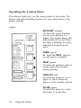
Operating the Control Panel
The indicator lights give you the current status of the printer. The
buttons and paper handling functions let you control many of the
printer settings.
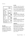
Lights
MULTI-PART (orange)
On when the paper thickness
lever is set to position 4 or
higher. (For regular paper, this
light should not be on.) When
this light is blinking, the microadjustment function can be
used.
POWER (green)
On when the POWER switch is
on and power is supplied.
READY (green)
On when the printer is ready to
accept input data. Flickers
during printing.
PAPER OUT (red)
On when the printer is out of
paper or when continuous
paper is in the standby position.
ON LINE (green)
On when the printer is on line
and ready to accept data.
3-2
Using the Printer
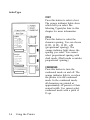
Buttons
ON LINE
This button controls the printer’s
on line and off line status. Press
this button to put the printer on
line or to take it off line. When the
printer is on line, the ON LINE light
is on and the printer can receive
and print data from the computer.
FORM FEED
When the printer is off line, press
this button to eject a single sheet
of paper or to advance continuous
paper to the top of the next page.
LINE FEED
When the printer is off line, press
this button to advance the paper
one line, or hold it down to
advance the paper continuously.
BIN 1/BIN 2
When the printer is on line,
press this button to select
either bin 1 or bin 2 of the
double-bin cut sheet feeder.
The beeper sounds once if
you select bin 1 and twice if
you select bin 2.
LOAD/EJECT
When the printer is off line, press
this button to feed paper to the
loading position or to eject paper
that is already loaded. Paper is
ejected forward if the paper
release lever is set to the singlesheet position and backward (out
of the paper path) if the release
lever is set to the continuous
paper position.
Using the Printer
3-3
SelecType
FONT
Press this button to select a font.
The orange indicator lights show
which font you select. See
Selecting Typestyles later in this
chapter for more information.
PITCH
Press this button to select the
character spacing. You can choose
10 CPI, 12 CPI, 15 CPI, or PS
(proportional spacing). The
orange indicator light shows the
spacing you select. You cannot
select proportional spacing with
draft mode. (Draft mode overrides
proportional spacing.)
CONDENSED
Press this button to turn the
condensed mode on and off. The
orange indicator light is on when
the printer is in the condensed
mode. In the condensed mode,
all characters are printed at
approximately 60 percent of their
normal width. You cannot select
condensed mode with a pitch of
15 cpi.
3-4
Using the Printer
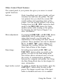
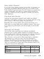
Other Control Panel Features
The control panel of your printer also gives you access to several
special functions.
Self test:
Draft, SuperDraft, and Letter Quality self test
functions are built into the printer. The self
test printout lets you check the current DIP
switch settings and operating status of the
printer. You can start the printer’s self test by
holding down the LINE FEED button (for draft
mode) or the FORM FEED button (for Letter
Quality mode) while turning on the printer.
See Running the Self Test in Chapter 1 for
more information.
Micro-adjustment:
By pressing the FORM FEED or LINE FEED button
immediately after loading paper or when
using short tear-off, you can make fine
adjustments to the loading and short tear-off
positions. These positions can only be adjusted
while the MULTI-PART light is blinking. See
Adjusting the Loading Position and Using
Short Tear-off later in this chapter.
Data dump:
By holding down both the LINE FEED and
FORM FEED buttons while you switch on the
printer, you turn on the data dump mode.
This feature allows advanced users to locate
the source of communications problems
between the computer and printer. See Using
the Data Dump Mode later in this chapter for
more information.
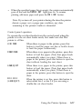
Input buffer control: To enable or disable the input buffer, press the
LOAD/EJECT button while you turn on the
power. The beeper sounds once if the input
buffer is disabled and twice if it is enabled.
Using the Printer
3-5
Selecting Typestyles
You can produce a wide range of typestyles by selecting different
character fonts, widths, and other enhancements from the SelecType
control panel or by using software commands. This section describes
only the features controlled by SelecType. To use software
commands, see the Command Summary in Chapter 9.
You can use the SelecType section of the control panel to choose
fonts, character spacing, and condensed printing. Orange lights
indicate which features you have chosen.
Note: The settings you select using the SelecType panel remain
valid even after you turn off, reset, or initialize the printer.
However, commands from your application program temporarily
override the SelecType settings.
Some application programs are designed to control all typestyle
functions. These programs cancel all previous typestyle settings
by sending certain software commands before printing. Because
these commands override SelecType settings, you should use the
program’s print options instead of SelecType to select your
typestyles. If SelecType does not work with a particular
application, check your software manual for instructions on
selecting typestyles.
Character Fonts
The printer has ten built-in fonts: draft, Epson Roman, Epson Sans
Serif, Epson Courier, Epson Prestige, Epson Script, OCR-B, OCR-A,
Epson Orator, and Epson Orator-S.
You can select eight of the built-in fonts using SelecType. When you
press the FONT button, the printer scrolls through the built-in fonts
on the control panel.
3-6
Using the Printer
To select a font, press the FONT button until the corresponding
orange indicator light (or lights) come on. When the top light is on,
draft is selected. When the top two lights are on, Epson Roman is
selected. When only the second light is on, Epson Sans Serif is
selected. When the second and third lights are on, Epson Courier is
selected, and so on.
You can select the other two fonts, OCR-A and
Orator-S, only with software commands. See
ESC K in Chapter 9 for more information. When
you select one of these fonts, the OTHER indicator
light is on.
There are two printing speeds for the draft font,
SuperDraft and normal draft. These printing
speeds are controlled by DIP switch 1-6.
The following samples show the character set
available for each font.
Draft (SuperDraft)
Draft (normal draft)
Using the Printer
3-7
Epson Roman
Epson Sans Serif
Epson Courier
Epson Prestige
Epson Script
3-8
Using the Printer
OCR-B
OCR-A
Note: The OCR-B and OCR-A fonts can be read by an optical
character reader (also known as a document reader or image scanner)
for input into another computer. Print enhancements, such as bold
and underlining, cannot be read by a character reader.
Epson Orator
Epson Orator-S
Using the Printer
3-9
The draft mode uses fewer dots per character for high-speed
printing, which makes it ideal for rough drafts and editing work.
Letter Quality fonts take a little longer to print, but produce nicely
formed characters suitable for most documentation requirements.
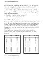
Character Spacing
To select character spacing, press the PITCH button until the indicator
light of the desired character spacing comes on. The table below
shows the character spacings available with each font.
Font
Draft
Epson Roman
Epson Sans Serif
Epson Courier
Epson Prestige
Epson Script
OCR-B
OCR-A
Character spacing
10, 12, 15
10, 12, 15, Proportional
10, 12, 15, Proportional
10, 12, 15
10, 12, 15
10, 12, 15
10
10
Epson Orator
10
Epson Orator-S
10
SuperDraft and normal draft fonts cannot be combined with
proportional spacing because draft overrides proportional.
For the fixed pitch settings (10,12, and 15 cpi), each character is
given an equal amount of space. For proportional spacing, character
width varies from one character to the next. For example, a narrow
letter like i receives less space than a wide letter like W.
3-10
Using the Printer
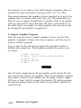
The following printout compares the three pitches with proportional
spacing.
This is 10 cpi printing.
This is 12 cpi printing.
This is 15 cpi printing.
This is proportional spacing.
Condensed Mode
You can use the condensed mode to change the size of printed
characters. In the condensed mode, characters are approximately 60
percent of the width of normal characters. Hence, condensed
printing is very useful for spreadsheets and other applications where
you need to print the maximum amount of information on a page.
You can combine the condensed mode with 10 and 12 cpi printing
and proportional spacing, but not with 15 cpi.
To select the condensed mode, simply press the CONDENSED button
so that the orange indicator light comes on. To turn off the
condensed mode, press the button again.
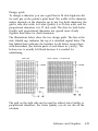
The following printout compares normal 10 and 12 cpi with
condensed 10 and 12 cpi. The condensed 10 cpi is 17 cpi, and the
condensed 12 cpi is 20 cpi.
This is 10 cpi printing.
This is condensed 10 cpi printing.
This is 12 cpi printing.
This is condensed 12 cpi printing,
Using the Printer
3-11
Setting the DIP Switches
The printer has two sets of DIP switches located on the back panel.
By changing the settings of these switches, you can control various
printer features, such as the character set and page length. The new
settings become effective when you turn on, reset, or initialize the
printer.
Changing a DIP Switch Setting
To change a DE’ switch setting, follow these steps:
1. Turn off the printer.
2. Locate the DIP switches on the back of the printer.
3. Use a pointed object, such as a pen, to change the DIP switch
settings. A DIP switch is on when it is up, and off when it is
down.
The new DIP switch settings take effect when you turn the printer on.
3-12
Using the Printer
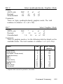
The DIP Switch Tables
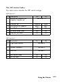
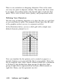
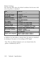
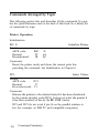
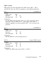
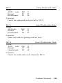
The tables below describe the DIP switch settings.
DIP Switch 1
S W Description
1-1
1-2
International character set/
Graphics character set
1-3
1-4 Character set
1-5 Print direction for graphics
1-6 SuperDraft
1-7 Cut sheet feeder mode
1-8 Skip over perforation
On
Off
See tables 1, 4
Graphics
Italics
Unidir.
Bidir.
Off
On
On
On
Off
Off
On
Off
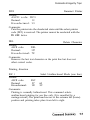
DIP Switch 2
SW Description
2-1
2-2
Page length selection
See table 5
2-3
2-4
Interface type/parity
See table 2
2-5
2-8
Baud rate
See table 3
2-7 Short tear-off mode
On
Off
2-8 Auto line feed
On
Off
Using the Printer
3-13
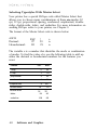
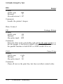
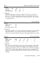
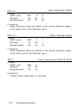
Table 1 International character sets
Country
USA
France
Germany
UK
Denmark I
SW 1-1 SW 1-2 SW 1-3 SW 1-4
On
On
Off
On
On
On
Off
Off
Off
On
Off
On
Off
On
Off
Off
Off
On
On
Off
Sweden
Off
On
Italy
Spain
Off
Off
Off
Off
Off
On
Off
Off
Off
Off
See Selecting an International Character Set later in this chapter for
other character sets.
International character sets are selectable only when DIP switch 14
is off.
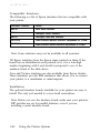
Table 2 Interface/parity selection
Interface type
Parity SW 2-3 SW 2-4
—
Off
Off
Serial
Even
On
Off
Serial
Odd
Off
On
Serial
None
On
On
Parallel
3-14
Using the Printer
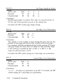
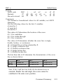
Table 3 Baud rate selection
Baud rate
SW 2-5 SW 2-6
Off
Off
Off
On
9600 bps
19200 bps
1200 bps
Off
On
300 bps
On
On
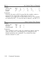
Table 4 Graphics character sets
Graphics character set
SW 1-1
SW 1-2
SW 1-3
SW 1-4
PC 437 (United States)
Epson Extended Graphics
On
On
On
On
PC 850 (Multilingual)
On
On
Off
On
PC 860 (Portugal)
On
Off
On
On
PC 863 (Canada-French)
On
Off
Off
PC 865 (Norway)
Off
On
On
On
On
Graphics character sets are selectable only when the DIP switch 1-4
is on.
The graphics character sets are also called code page tables.
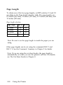
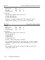
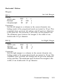
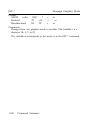
Table 5 Page length selection
Page length
11 inches
12 inches
8.5 inches
11.7 inches
SW 2-1 SW 2-2
Off
Off
On
Off
Off
On
On
On
Using the Printer
3-15
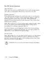
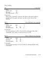
The DIP Switch Functions
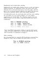
Auto line feed
When auto line feed is on (DIP switch 2-8 on), each carriage return
code (CR) is automatically followed by a line feed code (LF).
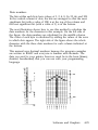
Printing direction
With unidirectional printing, the print head prints in one direction
only. This allows for precise vertical alignment, making it ideal for
printing graphics such as lines and boxes. With bidirectional
printing, the print head prints in both directions. This is faster than
unidirectional printing.
When DIP switch 2-6 is off, the printer prints unidirectionally; when
it is on, the printer prints bidirectionally. Either setting can be
overridden by a software command (ESC U).
To achieve precise vertical alignment without the slower printing
speed caused by unidirectional printing, see your Epson dealer for
adjustment of your bidirectional print settings.
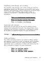
Tear-off mode
When DIP switch 2-7 is on, the short tear-off mode is on. This feature
automatically advances continuous paper to the tear-off position,
and then reverse-feeds the paper to the loading position. See Using
Short Tear-off later in this chapter.
CAUTION: Do not use the short tear-off mode with labels.
3-16
Using the Printer
SuperDraft
When DIP switch 16 is off, SuperDraft is selected. When the DIP
switch is on, normal draft is selected. SuperDraft prints at 300
characters per second but produces characters that are not as fully
formed as the ones produced with normal draft. If you select a
feature such as emphasized, double-strike, or condensed in
SuperDraft mode, the printing speed will temporarily switch to
normal draft speed until the enhancement is turned off. This allows
you to use any print enhancement without canceling SuperDraft.
Using the Printer
3-17
Page Length
To obtain one of the four page lengths, set DIP switches 2-1 and 2-2
according to the Page length selection table. The page lengths are:
8.5 inches (216 mm), 11 inches (279 mm), 11.7 inches (296 mm), and
12 inches (305 mm).
Page length selection
Page length
SW 2-1 SW 2-2
11 inches
Off
Off
12 inches
On
Off
8.5 inches
Off
On
11.7 inches
On
On
Note: Be sure to set the page length to match the paper you are
using.
Other page lengths can be set using the commands ESC C and
ESC C 0. See the Command Summary in Chapter 9 for details.
Note: If you are using the cut sheet feeder, the page length is
automatically set when you run the printer’s self test. For details,
see The Cut Sheet Feeder in Chapter 5.
3-18
Using the Printer
Skip Over Perforation
By changing the setting of DIP switch 1-8, you can set skip over
perforation to on or off. If this feature is on when using continuous
paper, a one-inch margin is provided between the last printable line
on one page and the first printable line on the next page. This feature
is very convenient if your application program does not provide for
top and bottom margins.
If you adjust your loading position correctly, you can get half of the
margin at the bottom of one page and half at the top of the next
page, as shown in the following illustration.
DIP switch 1-8 off (Skip over perforation off)
DIP switch 1-8 on (Skip over perforation on)
Using the Printer
3-19
Note: Most application programs take care of top and bottom
margins. Use skip over perforation only if your program does not
provide these margins.
The skip over perforation setting can be set to values other than
one inch by using the ESC N command. See the Command
Summary in Chapter 9 for details.
3-20
Using the Printer
Adjusting the Loading Position
The loading position is the position of the paper when it has been
automatically loaded by the printer.
This position is important because it determines where the printing
begins on the page. If the printing is too high or too low on the page,
change the loading position using the micro-adjustment feature
described in the next section.
You can set separate loading positions for single sheets, continuous
paper, and sheets loaded, by the cut sheet feeder.
CAUTION: Never use the platen knob to feed paper except
in case of a paper jam or other paper feeding problem. (If
you need to use the platen knob, make sure the power is
off.) If you need to adjust the loading position, always use
the micro-adjustment feature.
Until the loading position is reset, the printer remembers this
position even if it is turned off, and uses it as a reference point for
feeding paper.
The micro-adjustment feature moves the paper in 1/180-inch
increments to make fine adjustments to the loading position. You
can use this feature to adjust the loading position immediately after
loading paper only.
Once you have used micro-adjustment to change the loading
position of continuous paper, the printer remembers that position
even after it is turned off. However, when you use micro-adjustment
to change the loading position of single-sheet paper, the printer does
not remember this position after the power is turned off. When the
power is turned back on,, the loading position returns to its factory
setting.
Using the Printer
3-21
Using Micro-adjustment
1. Make sure that the printer is turned on and that either a single
sheet or continuous paper is ready to be loaded.
2. A single sheet loads automatically. For continuous paper, press
the LOAD/EJECT button to feed paper to the loading position.
Then press the ON LINE button; the MULTI-PART light begins to
blink.
Note: You can use the FORM FEED and LINE FEED buttons for microadjustment only while the MULTI-PART light is blinking.
3.
Press the FORM FEED button to feed the paper forward or the
LINE FEED button to feed the paper backward.
3-22
Using the Printer
Note: When the paper reaches the factory-set loading position, the
printer beeps and micro-adjustment feeding pauses for a moment
before continuing. You can use this factory setting as a reference
point when adjusting the printer’s loading position. When the
paper reaches either the minimum or maximum top margin, the
printer beeps and the paper stops moving.
Once you have adjusted your paper, the printer remembers this new
loading position. When the printer receives data, the MULTI-PART
light stops flashing.
Using the Printer
3-23
Using Short Tear-off
When you are finished printing, the short tear-off feature
automatically feeds the perforation of the continuous paper to the
tear-off edge of the printer cover so that you can tear off the last
sheet. When you resume printing, the paper feeds backward to the
loading position. This feature lets you save the paper normally lost
between documents.
Note: You can use the tear-off feature only with the built-in
tractor feeding system.
To use this feature, set DIP switch 2-7 to on. Then load continuous
paper in the normal way. Leave the paper guide cover open so that
you can use the cover’s tear-off edge.
You can leave the short tear-off feature turned on (DIP switch 2-7 on)
even when you are using single sheets. When you move the paper
release lever to the single-sheet position, the short tear-off feature is
disabled.
3-24
Using the Printer
CAUTION: Never use short tear-off with labels. Otherwise,
labels may come off their backing and jam the printer.
When you have finished printing, and if the perforation is at the top
of form position, the printer automatically feeds the perforation of
the continuous paper to the tear-off edge of the printer cover. You
can then tear off the page using the tear-off edge as shownbelow.
If the page perforation is not properly aligned with the tear-off edge,
you can adjust the tear-off position using micro-adjustment, as
described below.
Note: Short tear-off is performed whenever the printer receives a
full page of data or a form feed, and no more data is received for
three seconds.
When you resume printing after tearing off the sheet, the paper
automatically feeds backward to the loading position before printing
begins.
Using the Printer
3-25
Adjusting the Tear-off Position
If the paper’s perforation does not meet the tear-off edge, follow
these steps to adjust the tear-off position.
1. Make sure the printer feeds the paper to the tear-off position
after printing the document. The MULTI-PART light should begin
blinking, indicating that you can now use the micro-adjustment
feature to make fine adjustments to the tear-off position.
3-26
Using the Printer
2. To make fine adjustments to the tear-off position, press the
FORM FEED button to feed the paper forward or the LINE FEED
button to feed it backward.
You can now tear off your document from the perforation and
resume printing. The printer remembers this new tear-off position
even after the printer is turned off and on again.
Using the Printer
3-27
Selecting an International Character Set
International character sets provide you with characters and symbols
used in other languages. You can select one of eight international
character sets by changing the DIP switch settings.
Whenever the printer is turned on, reset, or initialized, the character
set selected by the DIP switches becomes the default character set.
To select an international character set, set DIP switches 1-1, 1-2, and
1-3 according to the table below. DIP switch 14 must be off.
This table also shows the characters that differ in each international
character set.
Country
DIP SW
ASCII code hex
23 24 40 5B 5C 5D 5 E 60 7 B 7C 7D 7 E
1-1
1-2
1-3
0 U.S.A.
ON
ON
ON
1 France
ON
ON
OFF
2 Germany
ON
OFF
ON
3 U.K.
ON
OFF OFF
4 Denmark
OFF
ON
ON
5 Sweden
OFF
ON
OFF
6 Italy
OFF OFF
ON
7 Spain I
OFF OFF OFF
Note: To change the setting of a DIP switch, first turn off the
printer, change the DIP switch setting, and then turn the printer
back on.
3-28
Using the Printer
In addition to the eight character sets shown on the previous page,
the seven international character sets that follow can be selected with
a software command, ESC R. For more information, see the
Command Summary in Chapter 9.
Country
ASCII code hex
23
24.
40
5B
5C
5D
5E
60
7B
7C
7D
7E
8 Japan
9 Norway
10 Denmark II
11 Spain II
12 Latin America
13 Korea
64 Legal
Once you set the DIP switches for a certain character set, that set
remains valid even after you turn off, reset, or initialize the printer.
Software commands, however, override the DIP switches settings
until the commands are canceled or the printer is turned off, reset, or
initialized.
Using the Printer
3-29
Choosing a Character Set
DIP switch 1-4 selects either the italic character set or a graphics
character set. The graphics character sets contain international
accented characters, Greek characters, mathematic symbols, and
character graphics for printing lines, comers, and shaded areas.
If you have an IBM or IBM-compatible computer, select a graphics
character set when you wish to print character graphics as they are
displayed on the screen. Even if you select a graphics character set,
you can still print ordinary text and italics. For italics, see your
software manual or the description of the ESC 4 command in the
Command Summary, Chapter 9.
®
Note: In most cases, a graphics character set is the preferred
selection.
To select either the italics or a graphics character set, set DIP switch
1-4 according to the table below.
Character set
DIP SW 1-4
Italics
Off
Graphics
On
Note: To change the setting of a DIP switch, first turn off the
printer, change the DIP switch, and then turn the printer back on.
You can also select the italics character set or a graphics character
set using the ESC t command. See the Command Summary in
Chapter 9.
3-30
Using the Printer
When DIP switch 1-4 is on, the graphics character set is determined
by the settings of DIP switches, 1-1,1-2, and 1-3.
Graphics character set
PC 437 (United States)
Epson Extended Graphics
PC 850 (Multilingual)
PC 860 (Portugal)
PC 863 (Canada-French)
PC 865 (Norway)
SW 1-1 SW 1-2 SW 1-3
On
On
On
On
On
Off
On
On
Off
Off
Off
On
On
On
Off
The graphics character sets are also called code page tables.
Sample printouts of the italic character set and the graphics character
sets are shown in the Appendix.
Note: When DIP switch 1-4 is off, DIP switches 1-1, 1-2, and 1-3
select an international character set.
Using the Printer
3-31
Using the Data Dump Mode
The data dump mode is a special feature that makes it easy for
experienced users to identify the cause of communication problems
between the printer and application programs. The data dump mode
gives a printout of the codes reaching the printer.
To use the data dump mode, follow these steps:
1. Make sure that the printer is loaded with either single-sheet or
continuous paper.
2. If the printer is on, switch it off; then hold down the FORM FEED
and LINE FEED buttons at the same time you turn on the printer.
3-32
Using the Printer
3. Run any program that causes the printer to print (either an
application program or one in any programming language).
Your printer prints out all the codes sent to the printer, as shown
below. (In order to print the last line, you will have to take the
printer off line.)
1B
2 0
6D
7 5
6 9
2 0
4 0 1B 5 2 0 0 1B 7 4 0 1
2 0 5 4 6 8 6 9 7 3 2 0 6 9
7 0 6C 6 5 2 0 6F 6 6 2 0
6D 7 0 2 0 6 F 7 2 6 9 6E
7 3 2 0 6 6 6 5 61 74 7 5
6 9 74 2 0 6 5 61 7 3 7 9
5 0 1B 7 0 0 0 2 0
6E 2 0 6 5 7 8 61
61 7 4 6 1 2 0 6 4
7 4 2E 2 0 5 4 6 8
6D 6 1 6B 6 5 7 3
7 2 2 0 2E 2E 2E
[email protected].
T h i s i s a n e x a
m p l e o f a d a t a d
ump orintout. Th
is feature makes
it easy for . . .
On the left side of the printout all the codes are printed in
hexadecimal format. On the right side of the printout all
printable characters are printed, and others, such as control
codes, are represented by dots.
4. To turn off the data dump mode press ON LINE to take the printer
off line. Then turn off the printer. (You can also cancel the data
dump mode by sending an INIT signal from the computer.)
Using the Printer
3-33
By comparing the characters printed in the text field on the right side
of the data dump printout with the printout of hex codes, you can
check which codes are being sent to the printer.
To interpret the data dump printout, examine the first three hex
codes on the second line of the printout sample (20 20 54). Each hex
code 20 represents a space; hex code 54 represents the letter T. Check
the second line of the text field on the right side of the printout and
you will find the letter T preceded by two spaces.
The chart below interprets the first eight codes.
Hex codes
Command
Function
1B 40
ESC @
Initialize printer
1B 52 00
ESC R0
Select USA character set
1B 74 01
ESCt1
Select PC 437 (Epson Extended Graphics)
3-34
Using the Printer
Chapter 4
Software and Graphics
Enhancing Your Printing . . . . . . . . . . . . . . . . . . . . . . . . . . . .
Print Quality and Fonts . . . . . . . . . . . . . . . . . . . . . . . . . . .
Character Spacing . . . . . . . . . . . . . . . . . . . . . . . . . . . . . . . .
Character Size . . . . . . . . . . . . . . . . . . . . . . . . . . . . . . . . . . .
Special Effects and Emphasis. . . . . . . . . . . . . . . . . . . . . . .
Selecting Typestyles With Master Select . . . . . . . . . . . . .
4-2
4-2
4-3
4-4
4-5
4-8
Graphics . . . . . . . . . . . . . . . . . . . . . . . . . . . . . . . . . . . . . . . . . .
The Print Head. . . . . . . . . . . . . . . . . . . . . . . . . . . . . . . . . . .
The Graphics Command . . . . . . . . . . . . . . . . . . . . . . . . . .
Column Reservation Numbers . . . . . . . . . . . . . . . . . . . . .
A Simple Graphics Program . . . . . . . . . . . . . . . . . . . . . . .
Designing Your Own Graphics . . . . . . . . . . . . . . . . . . . . .
4-10
4-11
4-14
4-15
4-16
4-17
User-defined Characters. . . . . . . . . . . . . . . . . . . . . . . . . . . . .
Designing Your Characters . . . . . . . . . . . . . . . . . . . . . . . .
Defining Your Characters . . . . . . . . . . . . . . . . . . . . . . . . .
Sending Information to Your Printer . . . . . . . . . . . . . . . .
Printing User-defined Characters . . . . . . . . . . . . . . . . . . .
Copying ROM Characters to RAM. . . . . . . . . . . . . . . . . .
Letter Quality Characters. . . . . . . . . . . . . . . . . . . . . . . . . .
Mixing Print Styles . . . . . . . . . . . . . . . . . . . . . . . . . . . . . . .
4-22
4-22
4-24
4-26
4-29
4-30
4-31
4-32
Software and Graphics
4-1
Enhancing Your Printing
You can obtain a wide variety of printing effects with your
printer from changing the number of characters per inch to using
special effects on selected words and phrases. This section gives
you a sampling of the features you may select with your
software.
For software control of these features, see the instructions for
your application programs or look up their specific commands in
the Command Summary in Chapter 9.
Print Quality and Fonts
The printer has three levels of print quality: SuperDraft, normal
draft, and Letter Quality (LQ). Draft printing speeds are controlled
by DIP switch 1-6.
SuperDraft is ideal for rough drafts and large documents or reports
that you need to print quickly. Normal draft takes a bit longer but
offers higher resolution characters. Finally, Letter Quality takes even
longer, but produces darker, more fully-formed characters suitable
for presentation-quality documents.
For Letter Quality printing, the printer offers nine fonts. See
Chapter 3 for information on the fonts and how to select them.
Note: SuperDraft is available only with 10 cpi printing.
Underlining and double-width printing can be combined with
SuperDraft. If other enhancements or character spacings are
selected, the printer switches to normal draft speed. SuperDraft
resumes again after the features are turned off.
4-2
Software and Graphics
Character Spacing
To add greater variety to your documents, the printer has three cpi
spacings, as well as proportional spacing. Each one can be selected
with a software command.
See Chapter 8 for a table that shows which character spacings
are available for each font. You cannot combine normal draft
mode with proportional spacing, and SuperDraft mode is
available only in 10 cpi printing.
The printout below compares the three spacings:
This is 10 cpi printing.
This is 12 cpi printing.
This is 15 cpi printing.
As shown above, 15 cpi characters are only about two-thirds the
height of 10 and 12 cpi characters. This makes 15 cpi particularly
useful when you want to separate certain material from the main
text.
In fixed cpi spacing each character is given the same amount of
space. The width of proportional characters, however, varies from
character to character. For example, a narrow letter like i takes less
space than a wide letter like W. The width of each proportional
character is given in the Appendix.
Software and Graphics
4-3
The following printout compares 10 cpi spacing with proportional
spacing:
This is 10 cpi printing.
This is proportional spacing.
Note: Proportional spacing is not available in the draft mode.
See the Print Size and Character Width commands in Chapter 9.
Character Size
In addition to the basic cpi spacings and proportional spacing, the
printer offers three other modes that can change the size of your
printing. These modes are double-wide, double-high, and
condensed.
The double-wide mode doubles the width of any size character,
while the double-high mode doubles the height of any size
character. These modes are useful for emphasizing document titles
and headings in reports, but are usually not suitable for large
amounts of text. These modes can also be combined to obtain even
more impressive printing results.
This is normal 10 cpi printing.
T
h
i
s
i
s
d
o
u
b
l
e
— w
i
d
t
h
.
This is double-height.
This is double-width
and double-height.
4-4
Software and Graphics
Both 10 and 12 cpi printing and proportional spacing can be
reduced to about 60 percent of their normal width using the
condensed mode. This mode is particularly useful for printing wide
spreadsheets because condensed 12 cpi printing allows you to print
up to 160 characters on an 8-inch line.
The condensed mode can be selected with a software command, or
by using SelecType (See Chapter 3). Even if you turn the condensed
mode on with SelecType, you can still turn it off with a software
command.
Condensed 10 cpi gives you many characters on & line,
Condensed 12 cpi giver even lore,
Widening or narrowing the characters also widens or narrows the
spaces between words. Because word processors usually create a left
margin by printing spaces, you may need to change the left margin
and the number of characters on a line to keep the margins correct if
you change character widths.
Note: You cannot condense 15 cpi.
SuperDraft temporarily switches to normal draft speed when
you select condensed printing.
See the Print Size and Character Width commands in Chapter 9.
Special Effects and Emphasis
The printer offers two ways of emphasizing text and also allows you
to use underlining, superscripts, subscripts, and italics. You can
directly control these features using software commands. Many
application programs can also produce some of these effects. See
your application program manual for details.
Software and Graphics
4-5
Emphasized and double-strike printing
Emphasized and double-strike printing can give words and phrases
added prominence. In emphasized mode, the printer prints each
character twice as the print head moves across the paper, with the
dots in the second pass printed slightly to the right of the first pass.
This process produces darker, more fully formed characters.
In double-strike mode, the print head prints each line twice, making
the text bolder. For even greater boldness, you can combine
emphasized and double-strike. The following samples show the
different effects you can achieve using these modes alone and in
combination.
This is ROMAN printing.
This is ROMAN, emphasized.
This is ROMAN, double-strike.
This is ROMAN, with both.
Note: SuperDraft temporarily switches to normal draft speed
when you select emphasized or double-strike printing. See the
ESC E and ESC G commands in Chapter 9.
Italic printing
You can print italics by using the ESC 4 software command (See
Chapter 9). This is true no matter how DIP switch 1-4 is set.
This is ROMAN printing.
This is ROMAN italics.
4-6
Software and Graphics
Underlining, strike-through, and overlining
The underline, strike-through, and overline modes are useful for
highlighting selected text. This feature can be used to score spaces,
subscripts, and superscripts without a break You can choose from a
variety of line styles, including single, double, broken, or
continuous. See the ESC ( - command in Chapter 9 for more
information.
This is continuous underlining.
This is broken overlining.
Superscripts and subscripts
Superscripts and subscripts can be used for printing footnote
numbers and mathematical formulas. The example below shows
underlining and subscripts combined in a mathematical formula.
See the ESC S command in Chapter 9 for more information.
average = ( a1 + a2 + . . . . . . . . . . + an)
n
Outline and shadow
The outline and shadow features are useful for adding variation
and emphasis to text that you wish to stand out, such as headings.
The following samples show the outline and shadow features
individually, plus a combination of outline with shadow. See the
ESC q command in Chapter 9 for more information.
Software and Graphics
4-7
Selecting Typestyles With Master Select
Your printer has a special ESCape code called Master Select that
allows you to choose many combinations of these nine modes: 10
cpi, 12 cpi, proportional spacing, condensed, emphasized, doublestrike, double-wide, italics, and underline. For more information on
sending ESCape codes to your printer, see Chapter 9.
The format of the Master Select code is shown below:
ASCII:
Decimal:
Hexadecimal:
ESC
27
1B
!
33
21
n
n
n
The variable n is a number that identifies the mode or combination
of modes. To find the value of n, use the following table to add up
either the decimal or hexadecimal numbers for the features you
want.
Feature
Dec.
Hex.
10cpi
0
00
12cpi
1
01
proportional
2
02
condensed
4
04
emphasized
8
double-strike
double-wide
italics
underline
4-8
16
32
08
10
20
64
40
128
80
Software and Graphics
For example, to print a title you may want to use double-wide 12 cpi
characters printed in the double-strike mode. You would add three
numbers together to calculate the value of n.
12cpi
1
Double-strike 16
Double-wide
32
n = 49
After calculating the value of n, you use the Master Select command
to send the value to the printer.
ASCII:
Decimal:
Hexadecimal:
ESC
27
1B
!
33
21
1
49
31
The print quality and font must be set separately, using SelecType
or the ESC x and ESC k commands. There are two more things to
consider when using the Master Select command:
l
l
Master Select cancels any of the other listed features that you do
not set. For example, if you have already set a different character
width and you use Master Select to set emphasized doublestrike, the character width is reset to 10 cpi.
Proportional spacing overrides 10, 12, and 15 cpi.
Software and Graphics
4-9
Graphics
The dot graphics mode allows your printer to produce pictures,
graphs, charts, or almost any other pictorial image you can create.
Because many commercial software programs use graphics, you
may be able to print pictures and graphs like the ones on this page
and the next by simply giving your software a few instructions.
The quickest and easiest way to print graphics on your printer is to
use a commercial graphics program. With such programs you
usually create an image on your monitor, then give a command to
send the image to the printer.
If you use commercial software that produces graphics, all you need
to know about dot graphics is how to use the software. The
application program will take care of the printer. (Some programs
call this bit image printing.) On the other hand, if you wish to do
your own programming or merely wish to understand how this
printer prints graphics, read on.
4-10
Software and Graphics
Income Breakdown
The Print Head
To understand dot graphics you need to know a little about how
your printer’s print head works.
The print head has 24 pins. As the print head moves across the page,
electrical impulses cause the pins to fire. Each time a pin fires, it
strikes the inked ribbon and presses it against the paper producing a
small dot. As the print head moves along, the pins fire time after
time in different patterns forming letters, numbers, and symbols.
Because the dots overlap each other both horizontally and vertically
in Letter Quality mode, it is difficult to see the individual dots.
Instead, the letters and symbols seem to be made up of unbroken
lines.
In order for the dots to overlap vertically, the pins in the print head
are in more than one column, but the intelligence of the printer
handles the timing of pin firings so that the effect is that of 24 pins
arranged in a single vertical column.
Dot patterns
The print head is able to print graphics, as well as text because
graphic images are formed on the printer in about the same way
that pictures in newspapers and magazines are printed. If you look
Software and Graphics
4-11
closely at a newspaper photograph, you will find that it is made up
of thousands of small dots. Your printer also forms its images with
patterns of dots, as many as 360 dots per inch, horizontally and 360
dots per inch, vertically. The images printed by this printer can,
therefore, be as finely detailed as the ones at the beginning of this
section.
Twenty-four-pin graphics
The graphics mode that takes full advantage of this printer’s print
head is 24-pin graphics. This mode has five densities, but for
simplicity this explanation deals with only one of them, tripledensity.
Triple-density prints up to 180 dots per inch, horizontally. As the
print head moves across the paper, every 1/180th of an inch it must
receive instructions about which of its 24 pins to fire. At each
position it can fire any number of pins, from none to 24. This means
that the printer must receive 24 bits of information for each column
it prints. Since the printer uses 8-bit bytes of information in
communicating with the computer, it needs three bytes of
information for each position.
4-12
Software and Graphics
Pin labels
To tell the printer which pins to fire in each column, you first divide
each of the vertical columns into three sections of eight pins each
and consider each section separately. Since there are 256 possible
combinations of the eight pins in each section, you need a
numbering system that allows you to use a single number to specify
which of the 256 possible patterns you want. This numbering
system is shown below:
128
64
32
16
8
4
2
1
To fire any one pin, you send its number to the printer. To fire more
than one pin at the same time, add up the numbers of the pins and
send the total. Using these labels for the pins, you fire the top pin by
sending 128. To fire the bottom pin, you send 1. If you want to fire
only the top and bottom pins, you simply add 128 and 1, and send
129.
By adding the appropriate label numbers together, you can fire any
combination of pins. Below are three examples of how to calculate
the number that will fire a particular pattern of pins.
Software and Graphics
4-13
With this numbering system, any combination of the eight pins adds
up to a decimal number between 0 and 255, and no numbers are
duplicated.
Because there are 24 pins in each column, you must make a
calculation for each of the three sections in each column. As you can
see, this method of planning and printing dot graphics requires
considerable calculation. Because triple-density uses 180 columns
per inch, printing a single line of triple-density graphics only one
inch long requires 540 numbers. Fortunately, commercial graphics
software is available to do these calculations for you.
Before you can put these numbers into a graphics program,
however, you need to know the format of the graphics command.
The Graphics Command
The graphics mode command is quite different from the other
commands used by the printer. For most of the other printer modes,
such as emphasized and double-wide, one ESC code turns the mode
on and another turns it off. For graphics, the command is more
complicated because the code that turns on a graphics mode also
specifies how many columns it will use. After the printer receives
this code, it interprets the numbers that follow as pin patterns and
prints them on the paper.
Your printer has one command that allows you to use any of the 11
graphics options. The format of the command is:
ESC * m n1 n2 data
4-14
Software and Graphics
In this command, m selects the graphics option and n1 and n2
specify the number of columns to reserve for graphics. The available
graphics options are listed below:
Pins
m
Single-density
8
0
Double-density
High-speed double-density*
8
1
8
2
Option
Quadruple-density*
CRT I
CRT II
l
Horiz. density
Dots/in.
60
120
120
8
3
240
8
4
80
8
4
90
Single-density
24
31
Double-density
24
33
60
120
CRT III
24
38
90
Triple-density
24
39
180
Hex-density*
24
40
360
Adjacent dots cannot be printed in this mode.
Column Reservation Numbers
The graphics command requires more than one number to specify
how many columns to reserve because one line can use thousands of
columns, but the printer does not use numbers larger than 255 in
decimal. Therefore the graphics mode command uses two numbers,
n1 and n2, for reserving columns.
To find n1 and n2, divide the total number of columns by 256. The
result is n2; the remainder is n1. Since the command is set up for two
numbers, you must supply two even if you need only one. When
you need fewer than 256 columns, just make n1 the number of
columns you are reserving and make n2 a zero.
Software and Graphics
4-15
For example, if you wish to send 1632 columns of graphics data, n1
should be 96 and n2 should be 6 because 1632 = 96 + (6 x 256).
The printer interprets the number of bytes specified by n1 and n2 as
graphics data, no matter what codes they are. This means that you
must be sure to supply enough bytes of graphics data or the printer
will stop and wait for more data and will seem to be locked. If, on
the other hand, you supply too much graphics data, the excess will
be interpreted and printed as regular text.
A Simple Graphics Program
This first program is just a simple example to show you how the
graphics command, column reservation numbers, and data can be
used in a BASIC program.
Type in and run the following program. Be especially careful to
include both semicolons. The program produces the printout you
see below:
10
20
30
40
50
WIDTH "LET:".255
LPRINT CHR$(27)"*"CHR$(32)CHR$(40)CHR$(0);
FOR X-1 TO 120
LPRINT CHR$(170);
NEXT X
Line 20 selects single-density 24-pin graphics mode (mode 32) and
also reserves 40 columns for graphics. Since 24-pin graphics requires
three bytes of data for each column, line 30 begins a loop to supply
120 bytes of data. Line 40 contains the number 170, which produces
the first pin pattern shown in the section on pin labels, and line 50
ends the loop.
4-16
Software and Graphics
Designing Your Own Graphics
With what you know now, you can use the simplest application of
graphics—calculating by hand the data to print the graphic image.
While this method is the most tedious, it helps you understand dot
graphics. It is also useful for small graphic elements that are used
many times.
The illustration below shows how you can use a grid on paper to
plan where you want dots to be printed. This grid is for a single line
of graphics 42 columns long. Since each line of 24-pin graphics is
approximately 1/8th of an inch high and since triple-density
graphics prints 180 dots per inch, horizontally, a design planned on
this grid will be about 1/8th of an inch high and less than 1/4th of
an inch wide.
The actual pattern that the printer prints on the paper is, of course,
made up of dots that overlap each other both vertically and
horizontally. The reason the planning grid uses an x for each dot is
that using an accurate representation of the dots makes calculating
the data numbers difficult because they cover each other. Therefore,
remember that each x represents the center of a dot, and the dots
actually overlap.
Software and Graphics
4-17
Write the assigned values of the pins next to your design, then total
the values for each column of dots. These totals are the values that
you send to the printer as graphics data to print the design.
Below is the same grid divided into three sections to make the data
calculation easier. At the bottom of each section of each column is
the total of the pin numbers for that section. This gives you the total
of 126 data numbers necessary to print this small figure.
4-18
Software and Graphics
Below is the BASIC program that prints the design shown on the
previous pages. Note that the data numbers in lines 80 through 140
are the same numbers that are at the bottom of each section in the
last illustration. The WIDTH statement in line 10 is for IBM PC
BASIC; the WIDTH statement format may be different for your
system.
10
20
30
40
50
60
70
80
90
WIDTH "LPT1:",255
LPRINT CHR$(27)"*"CHR$(39)CHR$(42)CHR$(0):
FOR X-1 TO 126
READ N
LPRINT CHR$(N);
NEXT X
LPRINT
DATA 0,0,63,0,0,127,0,0,255,0,3,255,0,15,255,0,31,255
DATA 0,127,255,0,255,255,1255,3,255,255,7,255,255,15,
255,255
l00 DATA 31,255,254,31,255,252,31,255,248,31,255,240,31,255,
224,31,255,192
110 DATA 31,255,0,31,252,0,31,240,0,31,224,0,31,128,0,31,240,0
120 DATA 31,255,192,28,255,224,28,127,240,28,15,248,30,0,252,
31,0,126
130 DATA 15,128,15,7,192,7,3,240,7,1,254,7,0,255,7,0,127,135
140 DATA 0,31,199,0,7,231,0,1,247,0,0,255,0,0,127,0,0,63
In this program, line 20 assigns the graphics option (24-pin tripledensity) with code 39. Code 42 sets the number of pin columns at 42.
Lines 80 through 140 contain 126 bytes of data (42-pin columns x 3
bytes) for each pin column. Lines 30 through 60 print the design that
you see below:
Software and Graphics
4-19
Notice that the dots overlap quite a bit. This design was printed
using the triple-density, 24-pin graphics option because the density
is the same (180 dots per inch) in both directions.
Adding the following lines to the preceding program causes the
pattern to print 10 times in a row as shown below:
15 FOR C=l TO 10; RESTORE
65 NEXT C
Individual graphics option commands
There are four individual graphics option commands that are very
much the same as the ESC * command, but each one works for only
one graphics option. All these commands are for 8-pin graphics
options. Note that the commands contain one less variable than the
ESC * command because they don’t need to select a graphics option.
The commands are shown below:
Command
Function
ESC format
ESC K
Single-density
ESC*0
ESC L
Double-density
ESC*1
ESC Y
Double-density, high-speed
ESC*2
ESC Z
Quadruple-density
ESC*3
l
Because of a difference in line spacing increments, the shape of
graphics figures produced on the printer with an 8-pin option is
different from the output from the same program on a 9-pin printer.
4-20
Software and Graphics
The reassigning command
The LQ-850 and LQ-1050 have a command that allows you to
change the graphics option assigned to any of the four individual
graphics option commands.
The command looks like this:
ESC ? s m
The letters represents the command that you wish to change the
assignment for (K, L, Y, or Z) and m is the number of the graphics
option that you want to assign to it. For example, to change the
ESC K command to use the CRT I graphics option, the command in
BASIC is:
LPRINT CHR$ (27);"?";"K";CHR$(4)
This is a quick way to change the aspect ratio of the design that you
are printing. Changing the graphics option will change the width
without changing the height. You should, however, make this
change with caution.
If you change one of the S-pin graphics options to a 24-pin graphics
option without changing the program that supplies the graphics
data, you will print garbage (if the program prints at all).
Remember, the 24-pin graphics options require three times as much
graphics data as the 8-pin graphics options.
Software and Graphics
4-21
User-defined Characters
With this printer, it is possible to define and print characters of your
own design. You can design an entirely new alphabet or typeface,
create special characters for use as mathematical or scientific
symbols, or create graphic patterns with user-defined characters to
serve as building blocks for larger designs.
Below, you can see samples of typefaces created with the userdefined character function.
You can make the task of defining characters easier by using a
commercial software program that assists you in creating characters
or simply supplies you with sets of characters already created. Also,
some popular software programs make use of the printer’s userdefined character function to enhance printouts. (These characters
are called download characters in some programs.)
The standerd ASCII characters are stored in the printer’s Read
Only Memory (ROM), and the user-defined characters are stored
in the printer’s Random Access Memory (RAM).
Designing Your Characters
User-defined characters are like dot graphics because you send the
printer precise instructions on where you want each dot printed. In
fact, planning a user-defined character is like planning a small dot
graphics pattern.
4-22
Software and Graphics
Design grids
To design a character you use a grid that is 24 dots high-one dot
for each pm on the printer’s print head. The width of the character
matrix depends on the character set in use. For draft characters, the
grid is nine dots wide, for Letter Quality it is 29 dots wide, and for
proportional characters it is 37 dots wide. The dots for both Letter
Quality and proportional characters are spaced more closely
together than those for draft characters.
The illustrations below show the two design grids. The line at the
side, labeled cap, indicates the top of a standard capital letter. The
line labeled base indicates the baseline for all letters except those
with descenders (the bottom parts of such letters as j and y). The
bottom row is usually left blank because it is needed for
underlining.
Draft pica
Letter quality / Proportional
The grid on the right side can be used for either Letter Quality or
proportional characters. For Letter Quality you do not use all the
columns.
Software and Graphics
4-23
There is one restriction in designing characters. Dots in the same
row may not print in adjacent columns. This means that there must
be an empty dot position both to the left and right of each dot that
prints. This is true in draft, Letter Quality, and proportional mode.
Defining Your Characters
The first step in defining characters is to place the dots on a grid just
as you want them to print. The examples shown here, like the ones
in the graphics section, use an x to represent each dot.
In the illustration below, you see a draft grid with a simple userdefined character planned on it.
Now you translate the dot pattern you’ve created on paper to a
numeric format so you can send the data to your printer. Every dot
has an assigned value. Each vertical column (which has a maximum
of 24 dots) is first divided into three groups of eight dots. Each
group of eight dots is represented by one byte, which consists of
eight bits. Hence, one bit represents one dot.
4-24
Software and Graphics
Data numbers
The bits within each byte have values of 1, 2, 4, 8, 16, 32, 64, and 128.
In the vertical column of dots, the bits are arranged so that the most
significant bit (with a value of 128) is at the top of the column and
the least significant bit (with a value of 1) is at the bottom.
The next illustration shows how to use this method to calculate the
data numbers for the character in this example. On the left side of
the figure, the data numbers are calculated for the middle column.
The value of each byte is calculated by adding the values of the rows
in which dots appear. The right side of the figure shows the whole
character with the three data numbers for each column indicated at
the bottom.
This manual uses decimal numbers because the program examples
are written in BASIC and everyone is familiar with decimals. The
data you send to your printer, however, must be in the form (binary,
decimal, hexadecimal) that you can use with your programming
language.
Software and Graphics
4-25
You have seen how to design a character by placing dots on a grid
and translating the dots to decimal equivalents. The last step in
defining a character is sending this information to your printer.
Sending Information to Your Printer
The printer loads characters in the print style (Letter Quality, draft,
or proportional) that the printer is currently using. It also records
whether italic, superscript, or subscript is turned on. This means
that if you want to print a character in italics, for example, you must
have the italic mode turned on when you define the character.
The command your printer uses to define characters is one of the
most complex in its repertoire. The format of the command is this:
ESC & 0 nl n2 d0 dl d2 data
The ESC & is simple enough. The 0 (which is ASCII code 0, not the
numerical zero in quotation marks) allows for future enhancements.
At this time, it is always ASCII 0.
You can define many characters with a single command. The values
nl and n2 are the ASCII codes of the first and last characters you are
defining. If you are defining only one character, nl and n2 are the
same. You can use any codes between decimal 32 and 127 for n1 and
n2, but it is best not to define decimal 32, which is the code for a
space. Also, you can use letters in quotation marks instead of ASCII
codes for nl and n2.
An example will show how to specify nl and n2. For instance, if you
wanted to redefine the characters A through Z, nl would be A (or
ASCII code 65) and n2 would be Z (or ASCII code 90). So the
command ESC & 0 AZ (followed by the appropriate data) would
replace the entire alphabet of capital letters.
4-26
Software and Graphics
Following the specification of the range of characters to be defined
in this command are three data bytes, d0, dl, and d2, that specify the
width of the character and the space around it. The left space (in dot
columns) is specified by d0, and the right space is specified by d2.
The second byte, dl, specifies the number of columns of dots that
are printed to make up the character. By varying the width of the
character and the spaces around it, you can create proportionalwidth characters that print at draft speed. The table below shows
the maximum values for these bytes.
Mode
Draft
d1
d 0 + d l + d 2
9
12
Letter Quality 10 cpi
29
36
Letter Quality 12 cpi
23
30
Proportional
37
42
The last part of the command to define your characters is the actual
data that defines the dot patterns for each character. Since it takes
three bytes to specify all the dots in one vertical column, your
printer expects dl x 3 bytes of data to follow d2.
Software and Graphics
4-27
This example of a character definition program should make this
clear:
10 LPRINT CHR$(27)"x0"
20 LPRINT CHR$(27)"&"CHR$(0);
30 LPRINT "@@";
40 LPRINT CHR$(1)CHR$(9)CHR$(1);
50 FOR I-1 TO 27
60 READ A: LPRINT CHR$(A);
70 NEXT I
80 LPRINT"@@@@@"
90 LPRINT CHR$(27)"%"CHR$(1);
100 LPRINT "@@@@@"
110 LPRINT CHR$(27)"%"CHR$(0);
120 LPRINT "@@@@@"
130 END
140 DATA 1,0,0,2,0,0,4,0,0
150 DATA 8,0,0,23,255,240,8,0,0
160 DATA 4,0,0,2,0,0,1,0,0
In line 10, the ESC x0 command selects draft printing.
The actual character definition starts in line 20. The two @ signs in
line 30 represent nl and n2, the range of characters being defined (in
this case, a range of 1). Line 40 contains d0, dl, and d2.
The information about the actual character design (which is
contained in the DATA statements at the end of the program) is sent
to the printer in the loop between lines 50 and 70.
Note: When defining Letter Quality or proportional characters,
put a WIDTH statement in your program to prevent carriage
return and line feed codes from interfering with your definitions.
4-28
Software and Graphics
Printing User-defined Characters
If you entered the previous program example, you defined an arrow
and placed it in the RAM location for ASCII code 64 (replacing the @
sign). You can now print out a three-line sample of your work. The
first and third lines (printed by lines 80 and 120) print the normal @
sign. The second line (printed by line 100) prints out the arrow that
you defined.
Run the program to see the printout below:
@@@@@
@@@@@
As you can see, both sets of characters (the @ from the original
characters in ROM that the printer normally uses and the alternative
character you defined) remain in the printer available for your use.
The command to switch between the two sets is used in line 90 and
110. It is:
ESC % n
If n is equal to 0, the normal ROM character set is selected (this is the
default). If n is equal to 1, the user-defined character set is selected.
If you select the user-defined character set before you have defined
any characters, the command is ignored and the ROM characters
remain in use.
You may switch between character sets at any time-even in the
middle of a line. To try this, place semicolons at the end of lines 80
and 100 in the program example.
Software and Graphics
4-29
Copying ROM Characters to RAM
After running the program, if you select the user-defined character
set and try to print other characters, the only one that will print is
your arrow. Since no other characters are in the printer’s userdefined RAM, there is nothing else to print. Other characters sent to
the printer do not even print as spaces; it’s as if they were not sent at
all.
In many cases, you will want to redefine only a few of the characters
to suit your needs-the rest of the alphabet will work fine as it is. As
you have seen, it is possible to switch back and forth, at will,
between the normal character set and your user-defined character
set. It is, however, rather inconvenient.
Therefore, your printer has a command that allows you to copy all
of the standard characters from ROM to the user-defined character
set.
The command format is as follows, where the value of n represents
the font family:
ESC: 0 n 0
Note: This command cancels any user-defined characters you
have already created. You must send this command to the printer
before you define characters.
If you use this command at the beginning of a program, then define
your special characters and select the user-defined set, you can print
with the userdefined set as your normal character set. You never
need to switch back and forth between sets.
4-30
Software and Graphics
Letter Quality Characters
If you select Letter Quality printing with the ESC xl command, you
can design user-defined characters using up to 29 columns of the
Letter Quality/Proportional grid. The dot columns are spaced closer
together horizontally than draft dot columns (the horizontal dot
spacing is 1/360th of an inch as opposed to 1/120th of an inch for
draft characters).
Proportional mode characters
Selecting the proportional character mode yields user-defined
characters of the highest resolution. You can design characters using
all 37 columns of the Letter Quality/Proportional grid.
Remember that in Letter Quality and proportional modes, as in
draft mode, you cannot place dots in adjacent columns. There must
be an empty dot position both to the left and right of each dot that
prints.
Superscripts and subscripts
You can also create superscript and subscript user-defined
characters. Just as Letter Quality characters are defined when the
Letter Quality mode is selected, superscript and subscript characters
are created when you select either superscript or subscript.
These characters can be used as either superscripts or subscripts.
The characters are exactly the same; only their placement is
different. The difference between these characters and regular
characters is that superscript and subscript characters are smaller.
They are a maximum of 16 dots high. Their maximum width in dot
columns is shown in the table below:
Mode
d1
d O + d 1 + d 2
Draft
7
12
Letter Quality
23
36
Proportional
23
42
Software and Graphics
4-31
Since superscript and subscript characters are smaller, when you
define them you only need two bytes of data for each vertical row of
dots. Design grids for these characters are shown in the figure
below:
Draft pica
Letter Quality
and Proportional
Mixing Print Styles
You can use each of the three userdefined character modes (draft,
Letter Quality, and proportional) in combination with most of your
printer’s various print styles. For instance, emphasized mode works
with userdefined characters. The characters you design are
enhanced to give this printing effect.
Mixing the three types of userdefined character sets is not possible.
For example, if you select draft and define some characters, then
select proportional and define some more, the first draft character
definitions are deleted. Only one type of character definition may be
stored in RAM at any time.
4-32
Software and Graphics
If you define characters in one mode, then switch to another mode
and select the user-defined character set, the command is ignored
and nothing is printed. The user-defined character definitions,
however, remain unaffected. If you switch back to the mode in
which they were defined, you can then select and print them.
Keep in mind that user-defined characters are stored in RAM, which
is not permanent memory. When the printer power is turned off or
the printer is initialized with the INIT signal, the user-defined
characters are lost. (Some computers do this each time BASIC is
loaded.)
Software and Graphics
4-33
Chapter 5
Using the Printer Options
The Cut Sheet Feeder . . . . . . . . . . . . . . . . . . . . . . . . . . . . . . .
Installation . . . . . . . . . . . . . . . . . . . . . . . . . . . . . . . . . . . . . .
Paper Handling . . . . . . . . . . . . . . . . . . . . . . . . . . . . . . . . . .
Testing the Printer in the Cut Sheet Feeder Mode . . . . .
Loading Envelopes . . . . . . . . . . . . . . . . . . . . . . . . . . . . . . .
Operating the Cut Sheet Feeder . . . . . . . . . . . . . . . . . . . .
Using Continuous Paper . . . . . . . . . . . . . . . . . . . . . . . . . .
Loading Single Sheets. . . . . . . . . . . . . . . . . . . . . . . . . . . . .
Removing the Cut Sheet Feeder . . . . . . . . . . . . . . . . . . . .
5-2
5-3
5-8
5-12
5-14
5-16
5-18
5-23
5-24
The Pull Tractor . . . . . . . . . . . . . . . . . . . . . . . . . . . . . . . . . . . .
Installation . . . . . . . . . . . . . . . . . . . . . . . . . . . . . . . . . . . . . .
Paper Handling . . . . . . . . . . . . . . . . . . . . . . . . . . . . . . . . . .
Removing the Pull Tractor. . . . . . . . . . . . . . . . . . . . . . . . .
5-28
5-28
5-31
5-37
The Interface Boards . . . . . . . . . . . . . . . . . . . . . . . . . . . . . . . .
Choosing an Interface. . . . . . . . . . . . . . . . . . . . . . . . . . . . .
Compatible Interfaces. . . . . . . . . . . . . . . . . . . . . . . . . . . . .
Installation . . . . . . . . . . . . . . . . . . . . . . . . . . . . . . . . . . . . . .
#8143 New Serial Interface. . . . . . . . . . . . . . . . . . . . . . . . .
5-41
5-41
5-42
5-42
5-55
Using the Printer Options
5-1
The Cut Sheet Feeder
The optional cut sheet feeder makes it possible to handle singlesheet paper more easily and more efficiently. Up to 150 sheets of
standard bond paper can be fed automatically into the printer
without reloading. You can also feed envelopes using the cut sheet
feeder.
You can use the following cut sheet feeders with the printers:
Printer
LQ-850
LQ-1050
Single bin
#7339
#7340
Double bin
#7346
#7348
The double-bin sheet feeders have a front bin (bin 1) and a back bin
(bin 2) in which you can store two different types of paper. You
select the bin to feed from through the control panel or using a
simple command.
The illustrations in this section show the single-bin feeder for the
LQ-1050. You use the other sheet feeders in the same way.
5-2
Using the Printer Options
Installation
1. Assemble the cut sheet feeder following the instructions
provided in its accompanying manual.
2. Make sure the printer is turned off. Then remove the printer
cover unit and the paper guide.
Using the Printer Options
5-3
3. Push the paper release lever back to the single-sheet position.
4. Remove the paper tension unit by pressing the levers back to
open the mounting latches. At the same time, lift up on the front
of the unit.
5-4
Using the Printer Options
5. Tilt the cut sheet feeder slightly forward to fit the notches at the
base of the unit over the pins on the printer. Then tilt the feeder
back until it rests on top of the printer.
6. Separate the paper guide cover (transparent gray plastic) from
the printer cover. With the underside of the paper guide cover
toward you, notice the two plastic tabs that secure the paper
guide cover to the printer cover. Press back on the inside edge of
each of these tabs to release the paper guide cover.
Using the Printer Options
5-5
7. Raise the cut sheet feeder’s paper path guide and attach the
printer cover.
5-6
Using the Printer Options
8. Close the paper path guide.
9. Turn on the cut sheet feeder mode by setting DIP switch 1-7
to on.
Using the Printer Options
5-7
Note: Always make sure that the printer is turned off before
changing the DIP switch settings.
10. Turn on the printer.
Paper Handling
1. Make sure that the cut sheet feeder mode is turned on with DIP
switch 1-7.
2. Pull the left and right paper set levers of the selected bin all the
way forward until the paper guides retract and lock open to
allow for paper loading.
Note: Make sure the front levers on the left and right paper
guides are up when using normal paper.
5-8
Using the Printer Options
3. Slide the left paper guide to where the fin on the edge guide
matches the arrow on the panel. Next, slide the right paper
guide so that it roughly matches the width of your paper.
4. Take a stack of paper and fan it as shown. This keeps the paper from
sticking and ensures that only one sheet feeds at a time. Tap the side
and bottom of the paper on a flat surface to even the stack.
Using the Printer Options
5-9
Note: For best results, use typewriter quality paper. If you
plan to use paper with a glossy or textured surface, test it
before using it to print documents. Do not use multi-part
forms, carbon paper, or labels in the cut sheet feeder.
5. Insert the stack of paper between the paper guides, aligning it
with the left edge of the guide. Then adjust the right paper guide
until the paper is held firmly, but not so tightly that it causes the
paper to buckle. Make sure the paper can move up and down
freely.
5-10
Using the Printer Options
6. Push the paper set levers back until they clamp the paper
against the guide rollers. The levers will not close completely if
too much paper is used. If this happens, remove some paper
from the stack and try again.
7. If you use the double-bin cut sheet feeder, you can select the
paper bin number with the control panel on the printer. When
the printer is on line, press the LOAD/EJECT button to change
between bin 1 and bin 2. The printer beeps once if you select
bin 1 and twice for bin 2. (You can also select the bin with the
ESC EM software command.>
LOAD / EJECT
Using the Printer Options
5-11
Testing the Printer in the Cut Sheet Feeder Mode
When you perform the cut sheet feeder self test, the printer counts
the number of lines on the page. As shown on the following page,
the number of lines counted is printed out at the bottom of the first
test page. This number is the default page-length setting. This
setting, however, can be overridden by software commands.
Running the self test is the same as when the cut sheet feeder mode
is off. The steps below are for a self test in draft mode.
1. Make sure that the printer is turned off and a stack of paper is
inserted in the selected bin of the cut sheet feeder. Check that the
cut sheet feeder mode is selected and the paper release lever is
pushed to the rear.
5-12
Using the Printer Options
2. While holding down the LINE FEED button, turn on the printer.
(For Letter Quality mode, press the FORM FEED button instead of
the LINE FEED button.)
A part of the printout of the first sheet is shown below. The
printout of the second sheet is similar to the original self test
described in Chapter 1.
Using the Printer Options
5-13
3. The self test continues until the paper runs out or until you press
the ON LINE button. To stop the test, press the ON LINE button.
Note: To resume the test, press the ON LINE button once more.
4. To end the self test when paper is loaded, press the LOAD/EJECT
button to eject the paper. Then turn off the printer.
Loading Envelopes
You can print on plain, bond, or air mail envelopes. The cut sheet
feeder can hold up to 25 plain or bond envelopes, or 30 air mail
envelopes. Before printing on envelopes, you need to set the paper
thickness lever. See Printing on Special Paper in Chapter 2.
WARNING: When you print on envelopes, be sure that the
settings of your application program keep the printing
entirely within the printable area.
You load envelopes in much the same way as regular paper.
1. Make sure that the paper release lever is in the single-sheet
position.
CAUTION: If you are using the double-bin cut sheet
feeder, be sure to load envelopes into bin 1, never into
bin 2. Make sure that you select bin 1 using the
LOAD/EJECT button or with the ESC EM software
command.
5-14
Using the Printer Options
2. Push down on the two front levers on the left and right paper
guides until they lock into position.
Using the Printer Options
5-15
3. Take a stack of envelopes and fan it; then tap the stack on a flat
surface to even the edges. Insert the envelopes into the front bin.
4. Press the LOAD/EJECT button to load an envelope. Then press the
ON LINE button to start printing.
Operating the Cut Sheet Feeder
After stacking paper in the cut sheet feeder, turn on the printer and
make sure that the ON LINE light is on. When the printer is on line, a
new sheet of paper loads automatically whenever a printable
character or line feed command is sent to the printer.
Paper out condition
When the printer is on line and receives print data from the
computer, the first sheet loads automatically. Subsequent sheets
load automatically as necessary.
l
In the cut sheet feeder mode, the PAPER OUT light goes off while
a sheet of paper is being fed, but the printer remains on line.
5-16
Using the Printer Options
l
When the specified paper bin is empty, the printer automatically
goes off line and the PAPER OUT light goes on. To resume
printing, add more paper and press the ON LINE button.
Note: If you turn off your printer during the time the printer
detects a paper out or paper jam condition, any data
remaining in the printer’s buffer is discarded.
Control panel operation
To operate the cut sheet feeder from the control panel when the
printer is in the cut sheet feeder mode, first make sure that the
printer is off line.
LINE FEED
When there is paper in the printer, press this
button to feed the paper one line or hold it down
to feed the paper continuously.
FORM FEED
When there is no paper in the printer, press this
button to load the paper. (Note that paper loads
automatically when you print.) When there is
paper in the printer, press this button to eject the
sheet without loading the next sheet.
LOAD/EJECT
When there is no paper in the printer, press this
button to load the paper. (Note that paper loads
automatically when you print.) When there is
paper in the printer, press this button to eject the
sheet.
BIN 1 BIN 2
(LOAD/EJECT)
When the printer is on line, press this button to
select either bin 1 or bin 2 if you are using a
double-bin cut sheet feeder.
Using the Printer Options
5-17
Software operation
The following commands cause the printer to eject the sheet in the
printer without loading the next sheet.
FF:
Form Feed
ESC EM R:
Ejects a sheet in the cut sheet feeder mode
Note: The ESC EM command is a software command used to
control the operation of the cut sheet feeder. For more
information about this command, see the Command Summary in
Chapter 9.
If the paper reaches the bottom of the print area when any of the
following line feed commands is used, the sheet in the printer is
automatically ejected and the next sheet is loaded.
LF:
Line Feed; advances the paper one line
VT:
Vertical Tab; advances the paper to the next
vertical tab position
ESC J:
Line feed; advances the paper n/l80th of an inch
Software is not effective while the printer is off line. Make sure that
the printer is on line if you wish to control the cut sheet feeder using
software commands.
Using Continuous Paper
The printer allows you to easily switch between the cut sheet feeder
and the tractor feeding system without having to remove either the
feeder or the continuous paper supply.
1. Make sure the continuous paper is already loaded and in a
standby position as explained in Chapter 2.
5-18
Using the Printer Options
2. Install the cut sheet feeder as described in this section, making
sure that DIP switch 1-7 is set to on.
3. If a single sheet is still in the printer, eject it by pressing the
LOAD/EJECT button.
Using the Printer Options
5-19
4. To switch from the cut sheet feeder to continuous paper, pull the
paper release lever forward to the continuous paper position.
You do not need to change the setting of DIP switch 1-7.
5-20
Using the Printer Options
5. Raise the paper path guide until it clicks open. This guide directs
the flow of continuous paper out of the front of the printer.
6. Press the LOAD/EJECT button to load continuous paper.
Note: With the paper release lever forward and the printer off
line, the control panel functions normally, allowing you to use the
micro-adjustment feature to finely adjust the loading position of
your paper.
CAUTION: Never attempt to print on labels when the cut
sheet feeder is installed.
To switch back to using the cut sheet feeder, follow these steps:
1. Tear off all printed sheets. Press the LOAD/EJECT button until the
continuous paper feeds backward out of the paper path.
Using the Printer Options
5-21
2. Close the paper path guide and set the printer on line.
3. Push the paper release lever back to the single-sheet position.
5-22
Using the Printer Options
Loading Single Sheets
Your cut sheet feeder also has a single-sheet loading feature. This
feature is especially useful because it allows you to switch to a
different type or size of paper without replacing the stack of paper
already in your cut sheet feeder.
1. Make sure that the paper release lever is in the single-sheet
position.
CAUTION: If you are using the double-bin cut sheet
feeder, make sure that bin 1 is selected by the LOAD/EJECT
button or with the ESC EM software command.
2. Press the ON LINE button to take the printer off line.
3. Align the single sheet to be fed with the mark on the left paper
guide. Then slide the sheet into the paper path until you feel
resistance.
Using the Printer Options
5-23
4. Press the LOAD/EJECT button to load the sheet.
Note: If you want to load two or more consecutive single sheets,
pull the paper set levers on the cut sheet feeder forward.
Removing the Cut Sheet Feeder
1. Turn off the printer and remove any paper stacked in the cut
sheet feeder.
2. Open the cut sheet feeder’s paper path guide and remove the
printer cover.
5-24
Using the Printer Options
3. Tilt the back of the cut sheet feeder forward to release its notches
from the printer’s pins. Then lift up and remove the cut sheet
feeder.
Using the Printer Options
5-25
4. Replace the paper tension unit as shown below. Tilt the unit
back and position the back notches on the unit over the rear
mounting pins of the printer. Press the levers open as you tilt the
unit toward you until the front latches click in place over the
front mounting pins located behind the paper bail.
5. Attach the paper guide cover to the printer cover as shown
below. Then install the printer cover unit onto the printer.
6. Set DIP switch 1-7 to off to turn off the cut sheet feeder mode.
Note: When DIP switch 1-7 is off, the printer uses the continuous
paper page length selected by DIP switches 2-1 and 2-2.
5-26
Using the Printer Options
Removal of the cut sheet feeder is now completed. Be sure to store
the removed cut sheet feeder in its original box and packing
materials.
Using the Printer Options
5-27
The Pull Tractor
The optional pull tractor provides optimum continuous paper
handling. The pull tractor is especially useful with continuous
preprinted forms, multi-part forms, and labels. Use of the pull
tractor is also recommended for obtaining the highest quality
graphics. For best results, use the pull tractor along with the built-in
push tractor as described in this section.
You can use the following pull tractors with the printers:
Printer
Pull tractor
LQ-850
#7311
LQ-1050
#7312
Installation
1. Turn off the printer and remove the printer cover unit and paper
guide.
2. Install the paper rest.
5-28
Using the Printer Options
3. Remove the paper tension unit by pressing the levers back to
open the mounting latches. At the same time, lift up the front of
the unit.
4. Hold the pull tractor with the knob to the right. Fit the rear
notches on the tractor over the rear mounting pins of the printer,
as shown in the following illustration.
Using the Printer Options
5-29
5. Tilt the tractor unit toward you until the front latches click in
place over the front mounting pins of the printer.
6. Pull the paper release lever all the way forward to the
continuous paper position.
CAUTION: You cannot use the short tear-off function with
the pull tractor. Before you start printing with the pull
tractor, be sure that DIP switch 2-7 is set to off.
5-30
Using the Printer Options
Paper Handling
1. With the printer cover unit removed, load continuous paper in
the push tractor as described in Chapter 2. However, position
the left sprocket unit about l/4 inch from the left before locking
it in place. When you have paper loaded, turn on the printer.
2. Make sure that the printer is off line and then press the
LOAD/EJECT button to load the paper. Next, press the FORM FEED
button to advance the paper one page so that you can fit the
paper onto the pull tractor.
Using the Printer Options
5-31
CAUTION: Never use the platen knob to feed the paper
while the printer is turned on. If you need to adjust the
loading position, use the micro-adjustment function
described in Chapter 3.
3. Open the sprocket covers of the pull tractor and pull the
sprocket lock levers toward you to release them.
5-32
Using the Printer Options
4. Adjust the sprocket units so that they are parallel with the push
tractor sprockets. Place the paper supports evenly between the
sprocket units. (There is only one paper support on the LQ-850.)
5. Fit the holes of the paper over the tractor pins on the sprocket
units, adjusting the position of the sprocket units as necessary.
Using the Printer Options
5-33
6. If the paper does not fit exactly onto the tractor pins or if the
paper buckles, press in on the pull tractor knob and turn it in the
desired direction until the paper fits properly.
7. Close the sprocket covers.
5-34
Using the Printer Options
8. See that the paper is not crooked or wrinkled and lock the
sprocket units in place.
CAUTION: Make sure that the sprocket units of the two
tractor units are properly aligned.
9. Slide the rollers on the paper bail bar so they are evenly
distributed across the width of your paper, making sure that the
right and left rollers are at both edges of your paper.
Using the Printer Options
5-35
10. Attach the paper guide. Then slide the edge guides together so
they meet at about the middle of the paper's width.
11. Install the pull tractor cover.
12. Press the ON LINE button to set the printer on line.
Note: Do not use the short tear-off feature with the pull tractor.
5-36
Using the Printer Options
Removing the Pull Tractor
1. Remove the pull tractor cover and the paper guide.
2. Tear off any printed sheets or extra blank sheets.
Using the Printer Options
5-37
3. P r e s s t h e O N
LINE button to take the printe
LOAD/EJECT button until the continuous paper fe
out of the paper path to the standby position. Th
light comes on when the paper is completely
path.
Note: Make sure you tear off the printed docu
removing paper with the LOAD/EJECT button. R
several pages at a time may result in a pap
5-38
Using the Printer Options
4. Remove the continuous paper from the push tractor unit. Then,
push the paper release lever backward.
5. Turn off the printer. Then, pressing the tabs on the pull tractor,
tilt it back and lift it off the printer.
Using the Printer Options
5-39
6. Replace the paper tension unit as shown below. Tilt the unit
back and position the back notches on the unit over the rear
mounting pins of the printer. Press the levers open as you tilt the
unit forward until the front latches click in place over the front
mounting pins located behind the paper bail.
7. Install the paper guide and the printer cover unit.
5-40
Using the Printer Options
The Interface Boards
A number of optional interfaces are available that supplement the
capabilities of your printer’s built-in serial and parallel interfaces.
Choosing an Interface
Optional interfaces can be divided into four main categories which
are described briefly below.
Serial interfaces are required if your computer is not equipped
with a parallel interface or if you need an interface that conforms
to the Current Loop standard instead of Rs-232C. These
interfaces also provide some combination of the following
features: X-ON/X-OFF data communication protocol, loopback
self test modes, and data buffers that increase the printer’s data
buffering capacity by 8 KB.
IEEE-488 interfaces offer standardized connections, trouble-free
operation, and the ability to connect computers, printers, and
other devices on the same line so that they may share data freely.
Third-party interfaces, such as Coax and Twinax, allow Epson
printers to function as local IBM printers without the addition of
any other circuitry or components.
The buffered parallel interfaces also offer trouble-free operation
and standardized connections. They provide the printer with
more memory to free the computer for other tasks when printing
large amounts of text or graphics. You can increase the printer’s
data buffering capacity by an additional 32 KB (about 10 pages).
If you are unsure whether you need an optional interface or would
like to know more about interfaces, contact your Epson dealer.
Using the Printer Options
5-41
Compatible Interfaces
The following is a list of Epson interfaces that are compatible with
your printer.
Interface number
Name
#8143
New serial interface
#8148
Intelligent serial interface
#8165
Intelligent IEEE-488 interface
C823032
32KB buffered parallel interface expandable to 512KB
C823021
32KB buffered serial interface expandable to 512KB
Note: Some interfaces may not be available in all countries.
All Epson interfaces have the Epson name printed on them. If the
board has an identification code printed on it, it is a four-digit
number beginning with 8 and should correspond to one of the
numbers listed in the table above.
Coax and Twinax interfaces are also available from Epson dealers.
These interfaces provide IBM emulation that allows you to connect
your printer to a mainframe or minicomputer.
Installation
The optional interface boards available for your printer are easy to
install. The only tool needed is a cross head screwdriver.
Note: Before you use the interface board, make sure your printer’s
DIP switches are set for parallel interface, even if you are
installing a serial interface board.
5-42
Using the Printer Options
Removing the upper case
1. Turn off the power to the printer and the computer. Next,
unplug the power cord from the electrical outlet and disconnect
the interface cable from the printer.
WARNING: High voltages are present inside the printer
when the power is on. Do not attempt to remove the cover
unless the printer is turned off and the power cord is
unplugged. Also, try not to touch contacts on the circuit
board of the printer because many of the components can
be destroyed by the static electricity that may build up on
your body.
2. Remove any installed printer options such as the pull tractor or
the cut sheet feeder. Then, remove the paper rest, the printer
cover unit, the paper guide, the paper tension unit, and the
platen knob. Remove the ribbon cartridge. Slide the print head to
the center of the printer.
Using the Printer Options
5-43
3. Using a cross-head screwdriver, remove the two retaining
screws: one located at the front of the printer, the other at the
back near the printer’s fan.
4. Detach the upper case by pressing in on the two retaining clips
inside the front of the printer. The clips on the upper case release
from the printer’s lower case.
5-44
Using the Printer Options
5. Partially raise the upper case. Look under the control panel and
notice the clip that secures the control panel to the upper case.
Now reach under the control panel and release the front clip.
6. Slip the control panel back through the upper case.
Using the Printer Options
5-45
7. With the control panel free of the upper case, tilt the case straight
back to detach the rear hinges, and then lift it off.
8. Remove the shield plate above the parallel interface by pressing
in on the plastic clips located at the back of the plate. (The
following illustration shows a rear view of the printer.)
5-46
Using the Printer Options
9. Remove the power cable attached to the main board by grasping
the clip at its base and pulling gently, but firmly, straight up.
You may need to move the clip back and forth slightly as you
pull upward to free it from the board.
10. Remove the screw labeled CG (chassis ground) from the main
board. The ground connector screw is located next to the power
cable connector. Then set it aside in a safe place.
Using the Printer Options
5-47
Installing the board
There are two basic types of interface board designs, which slightly
change the way they are installed in the printer. The frame ground
wire is attached for one type and not attached for the other. This
difference does not affect the operation of the interface in any way.
Check to see which type of interface board you have and then follow
the instructions for that type of board.
FG wire not attached
FG wire at attached
If the FG wire is not attached, follow these steps:
1. Set the DIP switches on the interface board according to the
manual accompanying your interface board. (If you are installing
the #8143 board, see the next section, #8143 New Serial Interface.)
5-48
Using the Printer Options
2. Use the CG screw to attach the round end of the FG wire to the
main board and position the other end as shown.
3. Reattach the power cable, making sure that the small fins on the
white plastic clip are toward the inside of the printer. Take extra
care to see that the holes of the clip are aligned with the pins of
the connector.
Using the Printer Options
5-49
4. Fit the interface board under the built-in tractor aligning the
board with the CN2 connector on the main board and with the
interface port of the back of the printer. Carefully insert the pins
on the optional interface board into the mating connector on the
main board. Then secure the board with three of the screws
provided.
5. Attach the plug end of the FG wire onto the FG pin located on
top of the interface board.
5-50
Using the Printer Options
If the FG wire is attached, follow these steps:
1. Set the DIP switches on the interface board according to the
manual accompanying your interface board. (If you are installing
the #8l43 board, see the next section, #8143 New Serial Interface.)
2. Carefully place the interface next to the printer as shown below.
Use the CG screw to connect the round end of the FG wire to the
main board.
Using the Printer Options
5-51
3. Reattach the power cable, making sure that the small fins on the
white plastic clip are toward the inside of the printer. Take extra
care to see that the holes of the clip are aligned with the pins of
the connector.
4. Holding the interface board level, rotate it clockwise into
position and attach it to the main board. Make sure the connector
pins are properly inserted into the mating connector.
5-52
Using the Printer Options
5. Secure the board with three of the screws provided.
Attaching the upper case
1. Fit the rear hinges of the upper case into the openings in the
lower case; then partially lower the upper case.
Using the Printer Options
5-53
CAUTION: Take care not to pinch the FG wire between the
upper and lower sections of the case.
2. Slide the control panel out through the upper case. Make sure the
control panel cable is clear of the upper case. Then reinsert the
control panel into the upper case. Press down on the front of the
control panel until the front clip snaps into place.
3. Close the upper case. Make sure you press down on the front of
the case until it locks into place.
5-54
Using the Printer Options
4. Secure the upper case with the two retaining screws.
5. Replace all parts and options you removed earlier.
CAUTION: Before you use the optional interface board, be
sure to disconnect the interface cable for the printer’s builtin parallel or serial interface. Two interface cables must not
be installed at the same time.
#8143 New Serial Interface
If you are using an optional interface, it may be necessary for you to
alter the communication protocol of the printer or the computer so
that they can communicate properly. In most cases, you should use
the information in your optional interface manual or your
computer’s manual to match the computer with the interface.
If you are using the #8143 optional interface board, make sure that
you read through the section below on baud rate selection. You may
also want to see the sections on handshaking timing and error
handling for interface information specific to the printer.
Using the Printer Options
5-55
For all other data transfer conventions, such as word structure or
communications protocol, use the information in the manual
supplied with your #8143 optional interface.
Baud rate selection
You can select baud rates from 75 to 19,200 BPS (Bits Per Second).
When setting the baud rate, make sure that your printer’s input
buffer is enabled by setting the LOAD/EJECT button (the beeper
sounds twice if the input buffer is enabled), and that you use the bit
rate selection table for printers with buffers (in the #8143 interface
manual).
For more information on the printer’s input buffer settings, see
Setting the DIP Swtiches in Chapter 3 of this manual.
Handshaking timing
When the vacant area for data in the input buffer drops to 256 bytes,
the printer outputs an X-OFF code or sets the DTR flag to 1 (MARK)
indicating that it cannot receive data.
Once the vacant area for data in the buffer recovers to 528 bytes, the
printer outputs an X-ON code or sets the DTR flag to 0 (SPACE)
indicating that it is again ready to receive data.
Error handling
When a parity error is detected, your printer prints an asterisk (*).
All other errors, including framing and overrun, are ignored.
5-56
Using the Printer Options
Chapter 6
Maintenance
Cleaning the Printer . . . . . . . . . . . . . . . . . . . . . . . . . . . . . . . .
6-2
Replacing the Ribbon . . . . . . . . . . . . . . . . . . . . . . . . . . . . . . .
6-4
Transporting the Printer. . . . . . . . . . . . . . . . . . . . . . . . . . . . .
6-9
Maintenance 6-1
Cleaning the Printer
To keep your printer operating at its best you should clean it
thoroughly several times a year. Follow the steps below:
1. Make sure that the printer is turned off. Then remove the paper
guide and any installed option
6-2 Maintenance
3. If the outer case or paper guide is dirty or dusty, clean it with a
soft, clean cloth dampened with a mild detergent solution. Keep
the printer cover in place to prevent water from getting inside
the printer.
WARNINGS:
l
Never use alcohols or thinners to clean the printer,
because these chemicals can damage the components
as well as the case.
l
l
l
Be careful not to get water on the printer mechanism
or electronic components.
Do not use a hard or abrasive brush.
Do not spray the inside of the printer with lubricants;
unsuitable oils can damage the mechanism. Contact
your Epson dealer if you think lubrication is needed.
Maintenance 6-3
Replacing the Ribbon
Replace the ribbon when the printout becomes too faint. The
following Epson replacement ribbon cartridges are available:
Printer
Standard ribbon
Film ribbon
LQ-850
#7753
#7768
LQ-1050
#7754
#7770
Notes:
l
Use the optional film ribbon only when you need especially
high quality printing. For everyday operations, use the
standard ribbon.
l
Do not use ribbons designed for nine-pin printers.
1. Make sure that the printer is turned off. Then remove the printer
cover unit.
WARNING: If the print head is hot, let it cool before
attempting to replace the ribbon.
6-4
Maintenance
2. To remove the ribbon cartridge, grip it by the two black handles
and lift the cartridge straight up and out of the printer. (Ribbon
cartridges #7753 and #7768 have only one handle.)
3. Slide the print head to the middle of the printer.
Maintenance 6-5
4. To remove slack in the new ribbon, turn the ribbon-tightening
knob in the direction of the arrow.
5. Push the new ribbon cartridge firmly into position, making sure
the plastic hooks fit into the slots, as shown below.
Note: Press lightly on both sides of the cartridge to make sure
the hooks are properly inserted.
6-6 Maintenance
6. Use a pointed object, such as a ballpoint pen, to guide the ribbon
between the print head and ribbon guide while you turn the
ribbon-tightening knob to help feed the ribbon into place. Be
careful not to puncture the ribbon.
7. Slide the print head from side to side to make sure it moves
smoothly. Also see that the ribbon is not twisted or creased.
Maintenance 6-7
8. Reattach the printer cover unit.
6-8
Maintenance
Transporting the Printer
Before you transport your printer some distance, carefully replace it
in the original box and packing materials, as described below.
1. Turn off the printer, then remove any installed options.
2. Unplug the power cord from the electrical outlet and disconnect
the interface cable between the printer and the computer.
3. Remove the printer cover unit and the paper guide.
4. Remove the ribbon cartridge and the platen knob.
Maintenance 6-9
5. Slide the print head to the middle of the printer. While holding
the paper bail bar open, reattach the left and right locking tabs.
6. Slide the print head all the way to the left. Using the enclosed
cross-head screwdriver, reattach the two red screws.
6-10
Maintenance
7. Insert the print head protector as shown below.
8. Reattach the printer cover unit.
WARNING: When you carry the printer, never hold it
by the compartment cover on the right side. If this cover
comes off, you may drop the printer.
Maintenance
6-11
9. Fit the printer back into the white packing material and then
back into its original box.
6-12
Maintenance
Chapter 7
Troubleshooting
Problems and Solutions . . . . . . . . . . . . . . . . . . . . . . . . . . . . . 7-2
Power Supply. . . . . . . . . . . . . . . . . . . . . . . . . . . . . . . . . . . . . . 7-4
Printing . . . . . . . . . . . . . . . . . . . . . . . . . . . . . . . . . . . . . . . . . . . 7-5
Paper Handling . . . . . . . . . . . . . . . . . . . . . . . . . . . . . . . . . . . . 7-16
Options.. . . . . . . . . . . . . . . . . . . . . . . . . . . . . . . . . . . . . . . . . . 7-27
Troubleshooting 7-1
Problems and Solutions
This chapter discusses problems you may encounter while
operating your printer and their likely solutions. If you are having
difficulty achieving the desired printing result, first locate the
problem in the table below and then see the appropriate page for the
solution.
Power supply
l
Power is not being supplied.
See 7-4
Printing
l
The printer does not print.
See 7-5
l
The print is faint or uneven.
See 7-6
Dots are missing in the printed characters
or graphics.
See 7-7
l
Printed characters are not what you expected.
See 7-8
l
The print position is not what you expected.
See 7-11
l
Paper handling
7-2
Single sheets do not feed properly.
See 7-16
Continuous paper does not feed properly
when using the push tractor.
See 7-19
Switching between single sheets and continuous
paper cannot be performed properly.
See 7-24
The short tear-off function does not operate
properly.
See 7-26
Troubleshooting
Options
l
l
l
Using the cut sheet feeder, the paper does not
feed properly.
See 7-27
Using the pull tractor with the push tractor,
continuous paper does not feed properly.
See 7-31
Using an optional interface, the printer does
not operate properly.
See 7-35
Troubleshooting 7-3
Power Supply
Problem
Solution
Power is not being
supplied.
The POWER light does
not go on.
The power cable may not be properly
plugged into the electrical outlet. Turn off
the printer and properly plug the power
cable into the electrical outlet.
The power switch is off. Turn it on.
Power is not being supplied to the
electrical outlet. Plug another electrical
device into the outlet to determine
whether the outlet is operating properly.
If the electrical outlet is controlled by a
switch, use an electrical outlet that is not
controlled by an outside switch.
The POWER light
comes on then goes off.
The light stays off even
when the power is
switched on again.
The voltage may not be correct for your
printer. Check the label on the printer’s
back panel and confirm that the printer’s
voltage rating matches your electrical
outlet. If the voltages do not match,
unplug 'the printer and contact your
Epson dealer immediately. Do not
reconnect the power cord to an electrical
outlet.
The problem may lie with the electrical
outlet. Plug another electrical device into
the outlet to determine whether the outlet
is operating properly.
7-4
Troubleshooting
Printing
Problem
Solution
The printer does not
print.
The ON LINE light is
on but nothing is
printed.
The software may not be installed
properly for your printer. Check the
printer settings and make the necessary
changes.
The interface cable may be loose. Check
both ends of the cable between the printer
and the computer. Secure the connector
using the wire retaining clips.
You may not be using the correct interface
cable. Make sure your interface cable
meets the printer and the computer
specifications.
The ON LINE light is
off.
The printer may be off line and cannot
receive data. Press the ON LINE button.
The ON LINE light should go on. See
Chapter 3.
The PAPER OUT light
is on.
The paper may be set too far to the right,
so that the paper detector cannot sense it.
Move the paper a little to the left. The
PAPER OUT light should go off.
The printer may be out of paper. Load more
paper into the printer. See Chapter 2.
Troubleshooting 7-5
Problem
Solution
The printer does not
print (continued).
The printer sounds like
it is printing, but
nothing is printed.
The ribbon cartridge may not be installed
properly. Turn off the printer, reinstall the
ribbon cartridge, and take up any slack in
the ribbon.
The ribbon may be worn. Replace the
ribbon cartridge. See Chapter 6.
The printer makes a
strange noise, the
buzzer sounds several
times, and the printer
stops abruptly.
This indicates an error in printer
operation. Turn off the printer, check for
paper jams or other problems, then turn
the printer back on. If the printer still does
not print correctly, contact your Epson
dealer.
The ON LINE light is
flickering but the
printer does not print,
or it stops printing
abruptly.
The print head is overheated. Wait a few
minutes; the printer resumes printing
automatically when the print head cools.
The print is faint or
uneven.
Printed characters have
parts missing at the
bottom as shown here.
ABCD
7-6 Troubleshooting
The ribbon cartridge may not be installed
properly. Remove the ribbon cartridge
and reinstall it. Make sure the cartridge
hooks are inserted securely into the
printer. See Chapter 6.
Problem
Solution
The print is faint or
uneven (continued).
The printout is faint.
The ribbon may be worn out. A worn
ribbon can damage the print head and
should be replaced. Install a new ribbon
cartridge. See Chapter 6.
The paper thickness lever may not be set
correctly for the paper you are using. Set
the paper thickness lever to match the
thickness of your paper. See Chapter 2.
Dots are missing
in the printed
characters or
graphics.
A line of dots is
missing in the
printout.
The print head is damaged. Stop printing
and contact your Epson dealer to have the
printer repaired.
ABCD
Dots are missing in
random positions.
ABCD
There is either too much slack in the
ribbon or the ribbon has come loose and
gotten caught on something. Stop
printing, turn off the printer, and reinstall
the ribbon cartridge. See Chapter 6.
Troubleshooting 7-7
Problem
Solution
Printed characters
are not what you
expected.
The typestyle or
characters that are set
by the software cannot
be printed.
The wrong
printed.
font is
italic characters are
printed instead of the
selected graphic “line”
characters.
The software may not be correctly
installed for your printer. Use the
program’s setup (or install) procedure to
check the printer settings, and reset as
needed.
Check your software manual, Chapter 3,
or Chapter 9 for information on using
fonts.
The wrong character table is selected. If
your application program is capable of
sending control codes, specify the Epson
Extended Graphics character table using
ESC t 1. See Chapter 9.
You can also select the graphics character
table by changing a DIP switch setting. To
do this, turn off the power, set DIP switch
1-4 to on, then turn on the printer. See
Chapter 3.
7-8
Troubleshooting
Problem
Solution
Printed characters
are not what you
expected
(continued).
Graphic characters or
lines are being printed
instead of the selected
italic characters.
The wrong character table is selected. If
your application program is capable of
sending control codes, specify the italic
character table using ESC t 0.
You can also select the italic character
table by changing a DIP switch setting. To
do this, turn off the power, set DIP switch
1-4 to off; then turn on the power. See
Chapter 3.
The wrong
international
characters are being
printed.
The wrong international character set is
selected. If your application program is
capable of sending control codes, specify
the desired international character set
using ESC R n. See the description of
ESC R in Chapter 9.
You can also select the international
character table by changing DIP switch
settings. To do this, turn off the power
and set DIP switches 1-1, 1-2, and 1-3 to
the correct positions for the character set
you want. See Chapter 3. You can check
the current DIP switch settings by
running the self test.
Troubleshooting 7-9
Problem
Solution
Printed characters
are not what you
expected
(continued).
The wrong graphics
characters are printed.
The wrong graphics character set is
selected. To set the desired graphics
character set, turn off the power and set
DIP switches 1-1, 1-2 and 1-3 to the
correct positions for the graphics
character set you want. See Chapter 3.
The characters printed
are smaller than
expected.
The condensed mode may be set. Check
to see if the CONDENSED light on the
control panel is on. If it is lit, press the
CONDENSED button to cancel the mode.
Also, if your application program is
capable of sending control codes, you
can cancel the condensed mode by
sending the DC2 code to the printer. See
Chapter 9.
The typestyle selected
by SelecType is not
printed.
The software may not be properly installed
for your printer. Use the program’s setup
(or install) procedure to check the printer
settings and reset as needed.
Your software may be overriding your
SelecType setting. If your program allows
you to change the printing style, software
control will override the SelecType
settings. For these application programs
use the program, not SelecType, to
change typestyles.
7-10
Troubleshooting
Problem
Solution
Printed characters
are not what you
expected
(continued).
The printer prints a
series of strange
characters.
Your printer and the computer may not
be communicating correctly. Make sure
that you are using the correct interface
cable and that the communication
protocol is correct. See your computer’s
manual for more information.
Make sure the interface cable is fastened
securely to both the printer and the
computer.
The print position is
not what you
expected.
Printing starts too high
or too low on the page.
The loading position may be incorrect.
Use micro-adjustment to adjust the
loading position. See Chapter 3. If the
problem persists, check the top margin
set by your application software and
adjust it.
Text is printed on the
same line.
A line feed signal is not being sent at the
end of each line of text. Change the auto
line feed setting with DIP switch 2-8. See
Chapter 3.
Text is printed with an
Two line feed signals are probably being
extra blank line in
between.
sent. Change the auto line feed setting
with DIP switch 2-8. See Chapter 3.
Troubleshooting
7-11
Problem
Solution
The print position is
not what you
expected
(continued).
Text is printed with an
extra blank line in
between, even after
setting the auto line
feed setting to off.
Your interface cable may not be
configured correctly. Disable the AUTO
FEED XT signal of your interface.
Line spacing is
incorrect.
Line spacing is too tight or too far apart.
If your application program is capable of
sending control codes, specify the line
spacing using ESC 0, ESC 2, ESC 3, or
ESC A. See Chapter 9.
One line of printing
has taken up two lines.
Auto line feed may be on. Turn off DIP
switch 2-8.
The margin setting may not be correct.
Use your application program to change
the margin.
In BASIC, enter either of the following
statements:
WIDTH LPRINT 255
WIDTH “LPT1” 255
If the printer still does not print properly,
set the right margin to the maximum
setting using ESC Q. See Chapter 9.
7-12
Troubleshooting
Problem
Solution
The print position is
not what you
expected
(continued).
Page length does not
match the length of the
paper.
The page length may be set incorrectly.
Change the page length setting with DIP
switches 2-1 and 2-2. See Chapter 3. If
your program allows you to send control
codes to the printer, specify page size by
sending ESC C or ESC C 0. See Chapter 9.
If this does not resolve the problem, check
the page length set by your application
software and adjust it if necessary.
If you are using the cut sheet feeder, the
self test function prints the number of
printable lines that can fit on a single
sheet. Use this feature to determine the
correct page length setting. See Chapter 5.
Regular gaps occur in
the printout.
One-inch skip over perforation may be
set. Set DIP switch 1-8 to off. See
Chapter 3. If your program allows you to
use control codes, use ESC O to cancel
skip over perforation. See Chapter 9.
Troubleshooting
7-13
Problem
Solution
The print position is
not what you
expected
(continued).
Skip over perforation is
set, but the perforation
does not fall in the
center of the skip.
The page length for continuous paper
may be set incorrectly. Set DIP switches
2-1 and 2-2 to the correct positions for the
page length you want. See Chapter 3. If
your program allows you to use control
codes, you can also use the ESC C or
ESC C 0 command to set the page length.
See Chapter 9.
The loading position of the paper may be
too high or too low. Use the microadjustment feature to reset the loading
position so that the perforation is
centered within the skip area. See
Chapter 3.
Your application program may be setting
the top and bottom margins. If this is the
case, turn off skip over perforation by
setting DIP switch 1-8 to off.
7-14
Troubleshooting
Problem
Solution
The print position is
not what you
expected
(continued).
Vertical printed lines
do not align or gaps
appear in lines or
graphics.
The printer is usually set for bidirectional
printing. This can cause a slight
misalignment of graphics characters.
When precise printing of vertical lines is
necessary, contact your service center to
have them perform the bidirectional print
alignment adjustment or select the
unidirectional print mode by sending
ESC U or ESC < to the printer. You can
also select unidirectional printing by
setting DIP switch 1-5 to on. See
Chapter 3. Unidirectional printing is
slightly slower. See Chapter 9.
If the printer still does not print, try the self test described in
Chapter 1. If the self test works properly, the printer is all right, and
the problem probably lies in the computer, the software, or the
cable. If the self test does not work, contact your Epson dealer.
Troubleshooting
7-15
Paper Handling
The following section guides you through problems in handling
single sheets and continuous paper. If you are having problems
using the optional cut sheet feeder or pull tractor, see the section on
options later in this chapter.
Problem
Solution
Single sheets do not
feed properly.
The LOAD/EJECT
button was pressed,
but the platen did not
move and paper was
not fed.
You may be trying to feed paper using
one of the control panel buttons while the
printer is on line (ON LINE light is on).
Press the ON LINE button once to take the
printer off line; then feed the paper. After
feeding the paper, press the ON LINE
button again to set the printer on line. See
Chapter 3.
The cut sheet feeder mode may be turned
on (DIP switch 1-7 is on). When you are
not using the cut sheet feeder, make sure
DIP switch 1-7 is off. See Chapter 3.
The left edge guide may be set too far to
the right so that the paper detector cannot
sense it. Move the paper a little to the left.
The PAPER OUT light should go off.
7-16
Troubleshooting
Problem
Solution
Single sheets do not
feed properly
(continued).
The LOAD/EJECT
button was pressed and
the platen rotated, but
paper was not fed.
The paper release lever may be set in the
wrong position. Push paper release lever
back to the single-sheet position. See
Chapter 2.
The left and right edge guides may be too
close together, preventing the paper from
feeding smoothly. Adjust the position of
the edge guides so that the paper can
move up and down freely. See Chapter 2.
The paper may not be firmly inserted.
When feeding thicker than normal paper,
press down lightly on the paper while
pressing the LOAD/EJECT button.
When the LOAD/EJECT
button is pressed, the
paper jams.
The edge guides may be too far apart.
Adjust the edge guides to the width of the
paper.
The dimensions of the paper may exceed
the specified limitations. Use only paper
sizes that are within the specified range.
Multi-part forms cannot be used with this
printer’s single-sheet feeding system. See
Chapter 8.
The paper guide may not be attached, or it
may not be in the correct position. When
printing on single sheets, use the paper
guide in its upright position. See Chapter 2.
Troubleshooting
7-17
Problem
Solution
Single sheets do not
feed properly
(continued).
When the LOAD/EJECT
button is pressed, the
paper feeds through
and then out of the
printer.
The paper may have been between the
edge guides before the printer was turned
on. When loading single sheets, be sure
that paper is not in the paper guide before
you turn the printer on.
The paper feed is
crooked.
The paper guide may not be attached, or
it may not be in the correct position.
When printing on single sheets, use the
paper guide in its upright position.
The paper may be dog-eared. Use new
paper.
The paper does not
fully eject.
You may be trying to eject the paper
using the FORM FEED button. Always
press the LOAD/EJECT button to eject the
paper.
The page length setting may be wrong. If
the page length is incorrectly set by your
software, the paper may not fully eject.
Check your software settings.
7-18
Troubleshooting
Problem
Solution
Continuous paper
does not feed
properly.
When the LOAD/EJECT
button is pressed, the
platen does not rotate
and paper does not
feed.
You may be trying to feed paper using the
control panel buttons while the printer is
on line (ON LINE light on). Press the ON
LINE button once to take the printer off
line, then try feeding paper. After feeding
paper, press the ON LINE button again to
set the printer on line. See Chapter 3.
The paper release lever may be pushed
back to the single-sheet position. When
using the push tractor, be sure the paper
release lever is pulled forward to the
continuous paper position. See Chapter 2.
When the LOAD/EJECT
button is pressed, the
platen rotates but
paper does not feed.
Continuous paper may have already been
in the paper path. (In this case, the paper
feeds backward to the standby position.)
Press the LOAD/EJECT button again to load
the paper.
Troubleshooting
7-19
Problem
Solution
Continuous paper
does not feed
properly
(continued).
The paper feed is
crooked or the paper
jams.
The paper supply may be obstructed by a
cable or some other object. Make sure that
the paper feeds smoothly into the printer.
See Chapter 2.
Your supply of continuous paper may be
too far from the printer. Position your
paper supply within 3 feet (1 meter) of the
printer. See Chapter 2.
The paper may be caught on the edge
guides. When using continuous paper,
make sure that the paper guide is
installed over the paper and that the edge
guides are positioned in the center. See
Chapter 2.
The holes on the sides of the paper may not
be aligned with each other. Reposition the
paper on the tractor pins. See Chapter 2.
The sprocket units are incorrectly
positioned for the paper width. Move the
right sprocket unit to remove any slack
across the width of the paper. See Chapter 2.
The position of your paper supply may be
preventing it from feeding straight. See
Chapter 2.
7-20
Troubleshooting
Problem
Solution
Continuous paper
does not feed
properly
(continued).
The paper feed is
crooked or the paper
jams (continued).
The sprocket lock levers may be
unlocked, or the sprocket covers may be
open. Position the sprocket units to match
the width of your paper. Then, lock them
in place by pressing the sprocket lock
levers away from you. See Chapter 2.
The paper guide may be in the upright
position. When using continuous paper,
make sure that the paper guide is in the
lowered position so that it can act as a
paper separator. See Chapter 2.
The paper thickness lever may be in the
wrong position. For printing on ordinary
paper, always set the lever to position 2.
The paper dimensions may exceed the
specified limitations. Use only paper sizes
that are within the specified range. Your
printer can print on continuous multi-part
forms consisting of 1 original and 3
copies. See Chapter 8.
Regular gaps occur in
the printout.
Skip over perforation may be interfering
with your application program settings.
Set DIP switch 1-8 to off. If your program
allows you to use control codes, you can
use ESC O to cancel skip over perforation.
Troubleshooting
7-21
Problem
Solution
Continuous paper
does not feed
properly
(continued).
Skip over perforation
does not function.
You may not have turned off the power
after setting DIP switch 1-8 to ON. To
make new DIP switch settings effective,
turn the power off, then on again.
Skip over perforation is
set, but the perforation
does not fall in the
center of the skip.
The page length for one page of
continuous paper may be set incorrectly.
Set DIP switches 2-1 and 2-2. See
Chapter 3. You can also use control codes
ESC C or ESC C 0 to set the page length
correctly. See Chapter 9.
The loading position of the paper may be
too high or too low. Use the microadjustment to reset the loading position.
See Chapter 3.
The loading position of
the paper shifts slightly
while printing several
pages.
The paper you are trying to feed may be
too heavy for the built-in push tractor.
When highly accurate paper feed is
necessary, such as when printing carbon
copies, use the optional pull tractor.
After printing stops,
the paper automatically
feeds forward.
The short tear-off function may be
selected. When you resume printing, the
paper feeds backward to its loading
position. If you do not need this function,
set DIP switch 2-7 to off. See Chapter 3.
7-22
Troubleshooting
Problem
Solution
Continuous paper
does not feed
properly
(continued).
The short tear-off
function is selected
(DIP switch 2-7 is on),
but it does not work.
You may not have turned off the power
after setting the DIP switch. To make new
DIP switch settings effective turn the
power off, then on again.
There may still be data in the print buffer.
The short tear-off function works only if
the data in the print buffer is completely
printed and the next print position is at
the top of the next page.
Your program may not be sending a form
feed command to the printer. At the end
of your program or the page, send a form
feed (FF). If you are using BASIC, be sure
to add a semicolon (;) after the FF code to
prevent any additional codes from being
sent to the printer.
The LOAD/EJECT
button is pressed to
eject the paper, the
paper feed stops, and
paper does not fully
eject or it jams.
You may have tried to back feed too
many pages. Before ejecting the paper,
always tear off the last printed page. See
Chapter 2
You may be trying to eject labels. Labels
may jam when they are fed backward, so
always use the FORM FEED button and
feed labels forward to eject them.
Troubleshooting
7-23
Problem
Solution
Continuous paper
does not feed
properly
(continued).
When printing labels,
the labels either do not
feed or feed incorrectly.
You may not be using the correct type of
labels. Read through the section on
printing on special paper for the correct
type of labels to use. See Chapter 2.
You may be trying to back-feed labels
through the printer. This can cause labels
to come off their backing and jam the
printer. Do not feed labels using the
LOAD/EJECT button. Also, make sure that
DIP switch 2-7 (short tear-off) is off.
If a label does become jammed in the
printer mechanism, see your Epson dealer
for assistance.
Switching between
single sheets and
continuous paper
cannot be
performed properly.
When the LOAD/EJECT
button is pressed to
load continuous paper,
the platen does not
rotate and the paper is
not loaded.
7-24
Troubleshooting
Pull the paper release lever forward to the
continuous paper position, set the paper,
then press the LOAD/EJECT button. See
Chapter 2.
Problem
Solution
Switching between
single sheets and
continuous paper
cannot be
performed properly
(continued).
The paper release lever
is correctly set for
continuous paper, but
when the LOAD/EJECT
button is pressed, the
platen rotates
backward and the
paper comes off the
sprockets.
A single sheet may be in the paper guide,
causing the continuous paper to back out
and to come off the sprockets. When
using continuous paper, always make
sure to remove any single sheets
remaining in the paper guide. See
Chapter 2.
When the LOAD/EJECT
button is pressed to
load a single sheet from
the paper guide, the
platen rotates in
reverse, the single sheet
does not load, and the
continuous paper
comes off the sprockets.
The paper release lever may not be in the
proper position. Push the lever back to
the single-sheet position, set the paper,
then press the LOAD/EJECT button.
Troubleshooting
7-25
Paper Handling
Problem
Solution
Switching between
single sheets and
continuous paper
cannot be
performed properly
(continued).
Even with the paper
release lever set
correctly to the singlesheet position, the
single sheet and
continuous paper feed
together and jam.
The continuous paper may not have fed
backward far enough to reach the standby
position before you changed the position
of the paper release lever. Remove the
jammed paper and try again. Also, check
that the PAPER OUT light comes on before
changing the position of the paper release
lever to make sure that the continuous
paper is completely ejected. When there is
more than one page to eject, you must
press the LOAD/EJECT button more than
once. See Chapter 2.
The short tear-off
function does not
operate properly.
One page is completely
printed, but the paper
does not feed.
DIP switch 2-7, short tear-off mode, may
be set to off. Set DIP switch 2-7 to on to
turn on the short tear-off mode.
Printing ended in the
middle of a page.
One page of data may not have been sent
to the printer. Finish the page by sending
a form feed code (FF) to the printer or by
sending enough line feed codes (LF) to
advance the remainder of the page.
7-26
Troubleshooting
Options
Problem
Solution
Using the cut sheet
feeder, the paper
does not feed
properly.
The LOAD/EJECT
button is pressed, but
the platen does not
move and the paper
does not feed.
You may be pressing the LOAD/EJECT
button while the printer is on line.
Always take the printer off line before
feeding the paper. Paper feeds
automatically when the cut sheet feeder
receives a print command from the
computer (only while the printer is on
line).
After a print command
is sent from the
computer, the platen
does not move and the
paper does not feed.
The printer may be off line. Press the
ON LINE button to put the printer on line.
The cut sheet feeder mode may be off.
Set DIP switch 1-7 to on. If your program
allows you to use control codes, use
ESC EM 4 to set the cut sheet feeder
mode. The printer must be ready with no
paper out condition to receive this
command. Send the command with
continuous paper loaded and with the
paper select lever in the continuous
position.
Troubleshooting
7-27
Problem
Solution
Using the cut sheet
feeder, the paper
does not feed
properly
(continued).
After a print command
is sent from the
computer, the platen
rotates, but paper does
not feed. The PAPER
OUT light is on.
DIP switch 1-7 is set to off. DIP switch 1-7
must be set to on in order to use the cut
sheet feeder. See Chapters 3 and 5.
The cut sheet feeder may be incorrectly
installed on the printer. Remove and
reinstall the cut sheet feeder making sure
that the mounting notches are properly
mated with the pins on the printer. See
Chapter 5.
The cut sheet feeder may be out of paper.
Load more paper in the cut sheet feeder’s
bin.
The paper release lever may not be in the
single-sheet position. Push the lever back
to the single-sheet position. See Chapter 5.
The paper set levers may be pulled
forward. After loading a stack of paper in
the cut sheet feeder, push the paper set
levers backward. See Chapter 5.
The left and right paper guides may be
too close together, preventing smooth
paper feed. Adjust the position of the
paper guides so that the paper can move
up and down freely. See Chapter 5.
7-28
Troubleshooting
Problem
Solution
Using the cut sheet
feeder, the paper
does not feed
properly
(continued).
After a print command
is sent from the
computer, the platen
rotates, but paper does
not feed. The PAPER
OUT light is on
(continued).
Paper may be jammed near the print
head. Remove the paper jam (temporarily
remove the cut sheet feeder if necessary).
You may have loaded too many sheets in
the cut sheet feeder’s bin. Remove the
sheets. The bin can hold a maximum of
150 sheets.
There may be only one sheet left in the
bin. The last sheet in the bin may not feed,
so add more paper.
Two or more sheets
feed at the same time.
You may have loaded too many sheets in
the cut sheet feeder’s bin. Remove the
sheets. The bin can hold a maximum of
150 sheets.
You may have forgotten to fan the stack
of paper before loading it into the bin.
Remove the paper and fan it. Then align
the edges of the stack. See Chapter 5.
Troubleshooting
7-29
Options
Problem
Solution
Using the cut sheet
feeder, the paper
does not feed
properly
(continued).
The paper feed is
crooked.
The paper may be old or creased. Discard
it and load new, clean sheets of paper.
The left and right paper guides may be
too far apart. Adjust the paper guides to
the width of the paper.
There may be too much outgoing paper.
Never let more than 80 sheets of outgoing
paper accumulate while printing.
The weight of your paper may be too
heavy or too light for the cut sheet feeder.
Refer to the specifications in Chapter 8
and make sure that your paper is the
proper size and quality.
You tried to manually
insert a single sheet,
but instead paper was
fed from the cut sheet
feeder's bin.
7-30
Troubleshooting
The single sheet may have been inserted
in the wrong place. Check it and try
again. See Chapter 5.
Paper may feed from the bin if you try to
insert several single sheets. To insert
several single sheets, pull the paper set
levers forward.
Options
Problem
Solution
Using the cut sheet
feeder, the paper
does not feed
properly
(continued).
One page of printing
has spread to two
pages.
The page length setting may be wrong.
Run a self test in cut sheet feeder mode.
The printer will automatically measure
the paper loaded and set the correct page
length. See Chapter 5.
You may have to change the top or
bottom margin or page length for your
application program.
When printing
envelopes, the
envelopes either do not
feed or feed incorrectly.
The two front levers may not be set to
envelope feeding. Push down on the two
front levers until they lock into position.
See Chapter 5.
Using the pull
tractor with the
push tractor,
continuous paper
does not feed
properly.
The FORM FEED or
LINE FEED button was
pressed, but the paper
does not feed at all.
(Platen does not
rotate.)
The printer may be on line. Before using
the control panel buttons to feed paper,
always take the printer off line (ON LINE
light out).
Troubleshooting
7-31
Problem
Solution
Using the pull
tractor with the
push tractor,
continuous paper
does not feed
properly
(continued).
Paper feed is crooked or
the paper jams.
Something may be obstructing the paper
feed, like an object on top of the paper
stack or a cable caught on the paper.
Make sure that nothing prevents the
smooth flow of paper and position the
paper so that it feeds straight in line with
the sprockets.
The supply of paper may be too far from
the printer. Position the paper supply so
that it is less than three feet or one meter
away.
The paper may be caught on the edge
guides. When using continuous paper,
make sure that the paper guide is lowered
over the paper and that the edge guides
are moved to the center of the paper’s
width. See Chapter 2.
The pull tractor and push tractor
sprockets are not aligned correctly. When
using both tractors, be sure that the
sprockets on both are positioned evenly.
See Chapter 5.
7-32
Troubleshooting
Problem
Solution
Using the pull
tractor with the
push tractor,
continuous paper
does not feed
properly
(continued).
Paper feed is crooked or
the paper jams
(continued).
The paper may be slack. Adjust the
position of the sprockets to take up any
slack along the width of the paper.
Remove slack lengthwise by pressing in
and rotating the pull tractor knob on the
right. Do not turn the platen knob.
The paper thickness lever may not be
correctly set. Set the paper thickness lever
to match the thickness of your paper.
The paper may not meet the
specifications. Check that your paper is
the proper size, weight, and thickness.
Several lines of space
occur in the printout.
Skip over perforation may be set. Set DIP
switch 1-8 to off.
Skip over perforation is
set, but it does not
work.
You may have changed the DIP switches
with the power on. To make new DIP
switch settings effective, turn the power
off, then on again.
Troubleshooting
7-33
Options
Problem
Solution
Using the pull
tractor with the
push tractor,
continuous paper
does not feed
properly
(continued).
Skip over perforation is
set, but the skip has
shifted from the
perforation, or the
perforation does not
fall in the center of the
skip.
The page length for one page of the
continuous paper may be set incorrectly.
Use DIP switches 2-1 and 2-2. See
Chapter 3. You can use control codes
ESC C or ESC C 0 to set the correct page
length. See Chapter 9.
When the printing
ends the paper feeds
abruptly, and as it
resumes printing, the
paper feeds backward
and comes off the pull
tractor sprockets.
The short tear-off function may be
selected. The short tear-off function
cannot be used with the pull tractor, so be
sure to set DIP switch 2-7 to off. See
Chapter 3.
When the LOAD/EJECT
button is pressed to
eject the paper, the
paper comes off the pull
tractor sprockets.
When the paper release lever is in the
continuous paper position, the paper
feeds backward to eject. When using the
pull tractor, press the FORM FEED button
to feed the paper forward to eject. See
Chapter 5.
7-34
Troubleshooting
The loading position of the paper may be
too high or too low. Use the microadjustment feature to reset the loading
position. See Chapter 3.
Options
Problem
Solution
Using an optional
interface, the printer
does not operate
properly.
The printer does not
print or the printout is
not what you expected.
The interface board may be loose or not
properly connected. Check that the
interface board is correctly inserted into
the connector on the main board. See
Chapter 5.
You may be trying to use an interface
with the wrong specification. Check the
specifications to make sure that you can
use the interface with this printer. See
Chapter 5.
The DIP switch settings may not be set
correctly. Make sure that DIP switches 2-3
and 2-4 are set for parallel, regardless of
whether the optional interface board is
parallel or serial. See Chapter 3. You can
also check the current DIP switch settings
by running the self test.
You may be trying to use a cable with the
wrong specification. Make sure that the
cable matches the specifications of the
interface.
The DIP switches or jumpers on the
interface board may be set wrong. See the
interface manual for the correct settings.
Troubleshooting
7-35
Problem
Solution
Using an optional
interface, the printer
does not operate
properly
(continued).
The printer does not
print or the printout is
not what you expected
(continued).
The interface settings on the computer
may be wrong. See your computer
manual for the correct settings.
The computer and interface settings may
not match. Match the settings for each
condition.
Two cables may be installed on the
printer; only one cable may be attached at
any time.
If the printer still does not operate properly after checking the above
points, run a self test of the interface to make sure that there are no
on-board defects. If any abnormality is found, contact your Epson
dealer.
Note: If you are still having problems after working through the
solutions in this section, you may want to try using the data
dump mode, a mode that helps advanced users determine the
causes of communication problems between the printer and the
computer. See Data Dump Mode in Chapter 3 for more
information.
7-36
Troubleshooting
Chapter 8
Technical Specifications
Printer Specifications . . . . . . . . . . . . . . . . . . . . . . . . . . . . . . .
Printing . . . . . . . . . . . . . . . . . . . . . . . . . . . . . . . . . . . . . . . . .
Paper.. . . . . . . . . . . . . . . . . . . . . . . . . . . . . . . . . . . . . . . . . .
Mechanical . . . . . . . . . . . . . . . . . . . . . . . . . . . . . . . . . . . . . .
Electrical . . . . . . . . . . . . . . . . . . . . . . . . . . . . . . . . . . . . . . . .
Environment. . . . . . . . . . . . . . . . . . . . . . . . . . . . . . . . . . . . .
8-2
8-2
8-4
8-8
8-9
8-9
Interface Specifications. . . . . . . . . . . . . . . . . . . . . . . . . . . . . . 8-10
Parallel Interface . . . . . . . . . . . . . . . . . . . . . . . . . . . . . . . . . 8-10
Serial Interface . . . . . . . . . . . . . . . . . . . . . . . . . . . . . . . . . . . 8-13
Option Specifications . . . . . . . . . . . . . . . . . . . . . . . . . . . . . . . 8-15
Cut Sheet Feeder . . . . . . . . . . . . . . . . . . . . . . . . . . . . . . . . . 8-15
Initialization . . . . . . . . . . . . . . . . . . . . . . . . . . . . . . . . . . . . . . . 8-17
Default Settings . . . . . . . . . . . . . . . . . . . . . . . . . . . . . . . . . . 8-18
Technical Specifications 8-1
Printer Specifications
Printing
24-pin impact dot matrix
Print method:
Print speed:
Quality
Characters per Inch
Characters/second/line
SuperDraft
10
300
Normal draft
10
246
12
295
10
82
12
98
Letter Quality
Printing direction:
Bidirectional logic-seeking for text and
graphics. Unidirectional for graphics.
(Unidirectional can be selected with a DIP
switch or by using the proper software
command.)
Line spacing:
l/6 inch or programmable in increments of
l/360 inch
Paper feed speed:
Single sheet: 3.0 inches per sec
(60 ms/line)
Continuous: 2.7 inches per sec
(65 ms/line)
8-2
Technical Specifications
Printable columns:
Maximum
printed characters
Character spacing
LQ-850 LQ-1050
10 cpi
80
136
10 cpi condensed
137
233
12 cpi
96
164
12 cpi condensed
160
272
6KB or 0KB (panel button selectable)
Buffer:
Character fonts:
Family
number
Draft
Available sizes
(Characters per inch)
10, 12, 15
Epaon Roman
10, 12, 15, Proportional
0
Epson Sans Serif
10, 12, 15, Proportional
1
Epson Courier
10, 12, 15
2
Epson Prestige
10, 12, 15
3
Epson Script
10, 12, 15
4
OCR-B
10
5
OCR-A
10
6
Epson Orator
10
7
Epson Orator-S
10
8
Font
Characters:
96 standard ASCII character set
(including italic characters)
14 international character sets
1 Legal character set
Epson Extended Graphics character set
5 graphics character sets
Technical Specifications 8-3
Paper
Paper feeding methods: Friction
Built-in push feed tractor with paper
tension unit
Pull tractor (optional)
Single-bin or double-bin cut sheet feeder
(optional)
Paper width and length:
Paper
Single sheet
width
length
Continuous paper
width
LQ-850
LQ-1050
7.2 to 10.1 inches
(182 to 257 mm)
7.2 to 14.3 inches
(182 to 364 mm)
7.2 to 14.3 inches
(182 to 364 mm)
7.2 to 14.3 inches
(182 to 364 mm)
4.0 to 10.0 inches
(101 to 254 mm)
4.0 to 16.0 inches
(101 to 406 mm)
Envelopes
No. 6
No. 10
Labels
2.5 x 0.94 inch (63.5 x 23.8 mm ) minimum
8-4
6.54 x 3.62 inches (166 x 92 mm)
9.45 x 4.09 inches (240 x 104 mm)
Technical Specifications
Printable area:
Single sheet
Note: For the LQ-850, printing on paper from 9 to 10.1 inches
wide increases the minimum right and left margins to 0.53 inches.
Technical Specifications 8-5
Continuous paper
Note: The minimum for the right and left margins increases to
0.98 inch (25.0 mm) when printing on IO-inch wide paper on the
LQ-850 or on l6-inch wide paper on the LQ-1050.
Envelope
Note: Envelope printing is only available at normal operating
conditions. Load the envelope with its long side horizontal.
8-6
Technical Specifications
Paper weight:
Single Sheet
Continuous
Multi-part
forms
Envelope
14 lb to 24 lb
14 lb to 22 lb
12 lb to 15 lb per sheet.
Maximum number sheets = 4
12 lb to 24 lb
Paper thickness:
Single Sheet
0.0025 to 0.0055 inch
(0.065 to 0.14 mm)
0.0025 to 0.012 inch
(0.065 to 0.32 mm)
0.0063 to 0.0197 inch
(0.16 to 0.52 mm)
maximum 0.0075 inch
(0.19 mm)
Continuous
Envelope
Label
Number of copies:
One original plus up to 3 copies
(at normal temperature)
One original plus up to 2 copies
(all temperature ranges)
Total thickness must not exceed 0.012 inch
(0.32 mm)
Notes:
l
The use of 24 lb paper is only available at normal temperature.
l
Printing past the edge of envelopes, multi-part forms, labels,
or paper that is thicker than normal can damage the print
head.
l
Labels with a pressure sensitive covering, either glued or
tacked onto the backing sheet, can be printed under the
conditions listed below. The total thickness may not exceed
0.0118 inch (0.3 mm).
- The temperature range is between 41°F and 95°F (5 to 35°C).
- The relative humidity is between 10 and 80 percent.
Technical Specifications 8-7
Mechanical
Black ribbon cartridge #7753/#7754:
Life expectancy (in Letter Quality
characters, at 48 dots/character)
2 million characters
Ribbon:
Film ribbon cartridge #7768/#7770:
Life expectancy (in Letter Quality
characters)
#7768: 0.2 million characters
#7770: 0.3 million characters
MCBF:
For all components excluding print head:
5,000,000 lines
MTBF:
LQ-850: 4000 power-on hours
(at 25% duty)
LQ-1050: 6000 power-on hours
(at 25% duty)
Print head life:
200 million strokes per wire
Dimensions and weight:
LQ-850 (80)
LQ-1050 (136)
Height
5.6 inches (142 mm)
5.6 inches (142 mm)
Width
17.0 inches (430 mm)
23.8 inches (606 mm)
Depth
14.2 inches (360 mm)
14.2 inches (360 mm)
Weight
approx. 19.8 lb (9 kg)
approx. 26.4 Ib (12 kg)
8-8
Technical Specifications
Electrical
Voltage:
120 VAC ± 10%
Power consumption:
(self test printing: draft mode)
LQ-850: 55 W
LQ-1050: 60 W
Frequency:
49.5 ± 0.5 Hz
Insulation resistance:
10M ohms between AC power line and
chassis
Dielectric strength
(between AC line
and chassis):
Can withstand 1.00 kV rms
applied for one minute or 1.20 kV rms
applied for one second
Environmental
Temperature:
Operation: 41°F to 95°F (5°C to 35°C)
Storage:
-22°F to 150°F (-30°C to 65°C)
Humidity (without
condensation):
Operation: 10% to 80%
Storage:
5% to 85%
Operation angle:
Less than 15° (without cut sheet feeder)
0° (with cut sheet feeder)
Shock:
Operation: Up to 1 G within 1 ms
Storage:
Up to 2 G within l ms
V&ration:
Operation: Up to 0.25 G at up to 55 Hz
Storage:
Up to 0.50 G at up to 55 Hz
Technical Specifications 8-9
Interface Specifications
Your printer is equipped with both a parallel and a serial interface.
For specifications on optional interfaces, see the manuals provided
with the interfaces.
Parallel Interface
Pin assignments for the parallel interface
Connector pin assignments and a description of their respective
interface signals are shown in the following table.
Signal Return
Pin
Pin
Signal
Direction Description
1
19
STROBE
IN
STROBE pulse to read data. Pulse
width must be more than 0.5
microseconds at the receiving terminal.
2
3
4
5
6
7
8
9
20
21
22
23
24
25
26
27
DATA 1
DATA 2
DATA 3
DATA 4
DATA 5
DATA 6
DATA 7
DATA 8
IN
IN
IN
IN
IN
IN
IN
IN
These signals represent information of
the 1st to 8th bits of parallel data,
respectively. Each signal is at HIGH
level when data is logical 1 and LOW
when it is logical 0.
10
28
ACKNLG
OUT
About an 11 -microsecond pulse. LOW
indicates that data has been received
and that the printer is ready to accept
11
29
BUSY
OUT
A HIGH signal indicates that the printer
cannot receive data. The signal goes
HIGH in the following cases:
1) During data entry (ea. char. time)
2) During printing
3) When off line
4) During printer-error state
8-10
Technical Specifications
Signal Return
Pin
Pin
Signal
12
30
Direction Description
PE
OUT
A HIGH signal indicates that the printer
is out of paper.
13
SLCT
OUT
Pulled to +5 volts through 3.3 Kohm
resistance.
14
AUTO
FEED
XT
IN
When this signal is LOW, the paper is
automatically fed 1 line after printing.
(The signal level can be fixed to this by
setting DIP switch 2-8 to on.)
15
NC
Not used.
16
GND
Logic ground level.
17
CHASSIS
GND
Printer's chassis ground, which is
isolated from the logic ground.
Not used.
18
19-30
NC
GND
31
INIT
32
ERROR
33
GND
34
NC
35
36
Twisted-pair return signal ground level.
IN
OUT
Same as for Pins 19-30.
Not used.
OUT
SLCT IN
When this level becomes LOW, the
printer controller is reset to its power-up
state and the print buffer is cleared. This
level is normally HIGH; its pulse width
must be more than 50 microseconds at
the receiving terminal.
This level becomes LOW when the
printer is:
1) in paper out state
2) off line
3) in error state.
IN
Pulled up to 5V through 3.3 Kohm
resistance.
The DC1/DC3 code is valid only when
this signal is HIGH. (Internal fixing can
be carried out with Jumper J1. The level
of this signal is factory-set to LOW.)
Technical Specifications
8-11
l
l
l
l
The column heading “Direction” refers to the direction of signal
flow as viewed from the printer.
“Return” denotes the twisted-pair return, to be connected at
signal ground level. For the interface wiring, be sure to use a
twisted-pair cable for each signal and to complete the connection
on the return side. These cables should be shielded and
connected to the chassis of the host computer and the printer.
All interface conditions are based on TTL level. Both the rise and
the fall times of each signal must be less than 0.2 microseconds.
Data transfer must be carried out by observing the ACKNLG or
BUSY signal. Data transfer to this printer can be carried out only
after receipt of the ACKNLG signal or when the level of the
BUSY signal-is LOW.
Interface timing
The figure below shows the timing for the parallel interface.
8-12
Technical Specifications
Printing enabled/disabled signals and control conditions
The table below shows the relationship between printing being
enabled or disabled, the on line/off line status, and the receipt of the
data on/off control characters, DC1 or DC3.
ON LINE SLCT IN DC1/DC3 ERROR BUSY
(Indicator
(Data
on/off
on)
control)
l
ACKNLG Printing
(Disabled/
enabled)
on line
Low (J9
DC1/DC3 High
interface) (no effect)
High/Low Pulsed
ea. char.
Enabled
(normal
cond.)
on line
High
DC1
Recv’d
High
High/Low Pulsed
ea. char.
Enabled
on line
High
DC3
Recv’d
High
High/Low Pulsed
ea. char.
Disabled*
off line
High/Low DC1/DC3 Low
(no effect) (no effect)
High
Not
generated
Disabled
While printing is disabled, character data is being received and acknowledged so
that the printer can look for another DC1 character, which would allow it to
resume printing.
Serial Interface
The LQ built-in serial interface is an RS-232C asynchronous interface
with the following characteristics:
Data format
1 start bit
Data word length: 8 bit
Odd, even, or no parity
1 stop bit
Baud rate
300, 1200, 9600, 19200 bits per second
Technical Specifications
8-13
Signal level
Mark (1) -3 V to -27 V
Space (0) +3 V to +27 V
Handshaking
Handshaking by DTR signal or X-on/X-off. The DTR signal changes
to mark-meaning the printer is not ready to receive data-when
the number of bytes free in the input buffer goes down to 256. The
signal changes to space-meaning that the printer is now readywhen the number of bytes in the input buffer rises to 528.
Error handling
A * character is printed if a parity error is detected. All other errors
are ignored.
Connector
6-pin DIN connector
In this table, the direction of signals is given relative to the printer.
Pin
Signal
number
Signal
direction
1
TXD
out
Transmits data for X-on/X-off
2
DTR
out
Indicates whether or not the printer is
ready to receive data. “Mark” level
indicates printer is not ready to
receive data.
3
RXD
in
Receives data
4
Not used
5
SG
-
Signal (logic) ground level
6
CG
-
Printer chassis ground
8-14
Technical Specifications
Direction
Option Specifications
Cut Sheet Feeder
Dimensions and weight:
Option no.
Height
Width
#7339
13.6 inches
(345 mm)
16.93 inches 14.33 inches
(430 mm)
(364 mm)
#7340
13.6 inches
(345 mm)
23.82 inches 14.33 inches 6.6 lbs
(3.0 kg)
(605 mm)
(364 mm)
#7346
14.45 inches 16.93 inches 20.20 inches 7.48 lbs
(3.4 kg)
(430 mm)
(367 mm)
(513 mm)
#7348
14.45 inches 23.82 inches 20.20 inches 9.9 lbs
(513 mm)
(367 mm)
(605 mm)
(4.5 kg)
Depth
Weight
4.84 lbs
(2.2 kg)
Dimensions: mounted on printer.
Bin and Stacker
capacity:
Single sheet: Up to 150 sheets of 22 lb
2
(82g/m ) paper
Up to 185 sheets of 17 lb
2
(64g/m ) paper
(total thickness should be up
to 0.59 inch or 15 mm)
Envelopes:* Up to 25 (plain and
bond type)
Up to 30 (air mail)
*For double-bin cut sheet feeder,
envelopes can only be used in bin 1.
Technical Specifications
8-15
Reliability (total cycle of bin 1 and bin 2)
100,000 cycles
MCBF:
Paper:
Single sheets
bin 1 and bin 2
Envelopes
bin 1
#7339
#7346
7.17 to 8.50 inches
(182 to 216 mm)
6.50 to 9.49 inches
166 to 241 mm)
#7340
#7348
7.17 to 14.33 inches
(182 to 364 mm)
6.50 to 9.49 inches
(166 to 241 mm)
8.27 to 12.00 inches
3.62 to 4.09 inches
Paper thickness
0.0028 to 0.0039 inch
(0.07 to 0.10 mm)
0.0063 to 0.0205 inch
(0.16 to 0.52 mm)
Paper weight
17 to 22 lb paper
(64 to 82 g/m2)
12 to 24 lb paper
(45 to 91 g/m2)
Paper width
Paper length
Paper storage
condition:
Temperature: 64°F to 72°F (18°C to 22°C)
Humidity:
40% to 60%
Environmental
Temperature:
Operation: 41°F to 95°F (5°C to 35°C)
-22°F to 158°F (-30°C to 70°C)
Storage:
Humidity (without
condensation):
Operation: 15% to 80%
5% to 90%
Storage:
Notes:
l
24 lb paper printing is only available at normal operating
conditions.
l
Envelope printing is only available at normal operating
conditions.
8-16
Technical Specifications
Initialization
There are three ways that the printer can be initialized (returned to a
fixed set of conditions).
Hardware initialization
l
l
Software initialization
l
The power is turned on.
The printer receives an INIT signal at
the parallel interface (pin 31 goes
LOW).
The software sends the ESC @
(initialize the printer) command.
These three kinds of initialization have slightly different effects. In
particular, ESC @ does not initialize the printer mechanism, clear the
input data buffer, or clear the user-defined character set.
Technical Specifications
8-17
Default Settings
The following table shows the default conditions that become valid
when the printer is initialized.
Item
Reset to:
Top of form position
Current paper position
Left and right margins
Cancelled
Line spacing
1/6-inch line spacing
Vertical tab position
Cleared
Horizontal tab positions
Every eight characters
VFU channel
Channel 0
Font selection
The current FONT button setting
Character spacing
The current PITCH button setting
Condensed mode
The current CONDENSED button setting
Special printing effects
User-defined characters
Cancelled (except condensed printing)
Hardware: Cleared
Software: Deselected only
Justification
Left justification
Graphic mode assignment
ESC K = ESC*0, ESC L = ESC*1,
ESC Y = ESC*2, ESC Z = ESC*3
In addition, the data buffer is cleared when the printer is initialized
by turning on the power or by sending an INlT signal.
Note: The user-defined character set is not cleared when the
printer is initialized by ESC @.
8-18
Technical Specifications
Chapter 9
Command Summary
Using the Command Summary. . . . . . . . . . . . . . . . . . . . . . . 9-2
Examples . . . . . . . . . . . . . . . . . . . . . . . . . . . . . . . . . . . . . . . . 9-3
Control Key Chart. . . . . . . . . . . . . . . . . . . . . . . . . . . . . . . . 9-4
Commands in Numerical Order . . . . . . . . . . . . . . . . . . . . . .
9-5
Commands Arranged by Topic. . . . . . . . . . . . . . . . . . . . . . . 9-8
Printer Operation. . . . . . . . . . . . . . . . . . . . . . . . . . . . . . . . . 9-8
MSB Control ..................................... 9-11
Data Control. . . . . . . . . . . . . . . . . . . . . . . . . . . . . . . . . . . . . 9-12
Vertical Motion . . . . . . . . . . . . . . . . . . . . . . . . . . . . . . . . . . 9-13
Horizontal Motion. . . . . . . . . . . . . . . . . . . . . . . . . . . . . . . . 9-19
Overall Printing Style . . . . . . . . . . . . . . . . . . . . . . . . . . . . . 9-22
Print Size and Character Width. . . . . . . . . . . . . . . . . . . . . 9-24
Print Enhancement . . . . . . . . . . . . . . . . . . . . . . . . . . . . . . . 9-28
Word Processing . . . . . . . . . . . . . . . . . . . . . . . . . . . . . . . 9-33
Character Sets . . . . . . . . . . . . . . . . . . . . . . . . . . . . . . . . . . . 9-34
User-defined Characters. . . . . . . . . . . . . . . . . . . . . . . . . . . 9-36
Graphics.. . . . . . . . . . . . . . . . . . . . . . . . . . . . . . . . . . . . . . . 9-38
Command Summary 9-1
Using the Command Summary
This chapter lists and describes all the commands available on the
printer.
The first part of this chapter lists all commands in numerical order
and gives the number of the page where each is fully described. If
you know which command you are looking for, consult the
numerical list.
Note: The Quick Reference card at the end of the book also
contains a list of the commands divided by topic, with page
number references that direct you to full explanations of the
commands.
The second part of this chapter lists and describes each command
separately; the commands are divided into the following subjects:
Printer operation
MSB control
Data control
Vertical motion
Horizontal motion
Overall printing style
Print size and character width
Print enhancement
Word processing
Character sets
User-defined characters
Graphics
Each command has a format section and a comments section. The
format section gives the ASCII, decimal, and hexadecimal codes for
the command. The comments section describes the effect of the
command and gives any additional information necessary for using
it.
The format section includes:
ASCII:
Decimal:
Hexadecimal:
9-2
the sequence in standard ASCII characters
the sequence in decimal numbers
the sequence in hexadecimal numbers
Command Summary
All three formats are equivalent, so you can pick the one best suited
to your purpose. Variables are represented by italicized letters such
as n, nl, and m. The variables are explained in the comments section.
Note: Some application programs use control key sequences. See
the Control Key Chart later in this chapter.
Examples
The simplest type of command consists of a single character to be
sent to the printer. For instance, to print in condensed mode, the
code format is:
ASCII code:
SI
Decimal:
15
Hexadecimal: OF
This code can be sent from a program by sending the code 15
directly.
More complex commands consist of two or more character codes.
For example, to print in double-wide mode, the code format is the
following:
ASCII code:
Decimal:
Hexadecimal:
ESC
27
1B
W
87
57
n
n
n
In this case n can be either 1 (on) or 0 (off), to begin or end doublewide printing. You can use either of the following commands to
turn on double-wide print from BASIC:
LPRINT CHR$(27);CHR$(87);CHR$(l)
LPRINT CHR$(27);"W";CHR$(l)
Command Summary 9-3
Using the Command Summary
For the following commands that use only 0 or 1 for the variable,
either the decimal or hexadecimal values 1 and 0 or the ASCII
characters 1 and 0 can be used:
ESC U, ESC x, ESC p, ESC W, ESC S, ESC-, ESC %, and ESC w.
For example, in BASIC you can turn on proportional spacing with
either of these statements:
LPRINT CHR$(27);"p";CHR$(l)
LPRINT CHR$(27);"p";"l"
Control Key Chart
Some application programs use control key codes for decimal values
O-27. The table below gives you the proper values. The Control Key
column indicates that you press the control key at the same time
you press the key for the letter or symbol in that column. For
example, you press the control key and A at the same time to send
the value 1.
Some application programs that use this system cannot use
Control-@, and many programs use the control keys for other
purposes.
D e c .
Hex.
Ctrl. Key
0
1
00
01
@
2
3
4
5
6
7
8
9
10
11
12
13
02
03
04
05
06
07
08
09
OA
OB
oc
OD
9-4
A
B
C
D
E
F
G
H
I
J
K
L
M
Command Summary
D e c .
Hex.
Ctrl. Key
14
15
16
17
18
19
20
21
22
23
24
25
26
27
OE
OF
10
11
12
13
14
15
16
17
18
19
1A
1B
N
O
P
Q
R
S
T
U
V
W
X
Y
Z
[
Commands in Numerical Order
The following list shows control codes and ESC sequences with
their decimal and hexadecimal values, and the page where the
description of the command can be found.
ASCII
BEL
BS
HT
LF
VT
FF
CR
so
SI
DC1
DC2
DC3
DC4
Dec.
7
8
Hex. Description
07
08
9
10
11
12
13
14
09
OA
OB
oc
OD
OE
15
17
18
OF
11
12
19
20
13
14
CAN
DEL
ESC SO
24
127
14
ESC SI
ESC EM
ESC SP
ESC!
ESC #
ESC $
ESC %
15
25
32
33
35
36
37
OF
19
ESC &
38
26
40
28
ESC (-
18
7F
OE
20
21
23
24
25
Beeper . . . . . . . . . . . . . . . . . . . . . .
Backspace . . . . . . . . . . . . . . . . . . .
Tab Horizontally . . . . . . . . . . . . .
Line Feed. . . . . . . . . . . . . . . . . . . .
Tab Vertically . . . . . . . . . . . . . . . .
Form Feed . . . . . . . . . . . . . . . . . . .
Carriage Return . . . . . . . . . . . . . .
Select Double-wide Mode
(one line) . . . . . . . . . . . . . . . . . . . .
Select Condensed Mode . . . . . . .
Select Printer. . . . . . . . . . . . . . . . .
Cancel Condensed Mode . . . . . .
Deselect Printer . . . . . . . . . . . . . .
Cancel Double-wide Mode
(one line) . . . . . . . . . . . . . . . . . . . .
Cancel Line . . . . . . . . . . . . . . . . . .
Delete Character. . . . . . . . . . . . . .
Select Double-wide Mode
(one line) . . . . . . . . . . . . . . . . . . . .
Select Condensed Mode . . . . . . .
Control Cut Sheet Feeder . . . . . .
Set Intercharacter Space . . . . . . .
Master Select. . . . . . . . . . . . . . . . .
Cancel MSB Control. . . . . . . . . . .
Set Absolute Print Position. . . . .
Select User-defined Set . . . . . . . .
Define Userdefined Characters
Select Score . . . . . . . . . . . . . . . . . .
Page
9-12
9-20
9-21
9-15
9-17
9-13
9-12
9-26
9-25
9-8
9-26
9-9
9-27
9-12
9-9
9-27
9-26
9-10
9-33
9-23
9-11
9-20
9-37
9-36
9-31
Command Summary 9-5
Hex.
Description
Page
42
43
45
2A
2B
2D
9-39
9-15
ESC /
ESC 0
ESC 2
ESC 3
ESC 4
ESC 5
ESC 6
ESC 7
ESC :
ESC <
47
48
50
51
52
53
54
55
58
60
2F
30
32
33
34
35
36
37
3A
3C
ESC =
ESC >
ESC ?
ESC @
ESC A
ESC B
ESC C
ESCCO
ESC D
ESC E
ESC F
ESC G
ESC H
ESC J
ESC K
61
62
63
64
65
66
67
67
68
69
70
71
72
74
75
3D
3E
3F
40
41
42
43
43
44
45
46
47
48
4A
4B
ESC L
76
4C
ESC M
77
4D
Select Graphics Mode . . . . . . . . .
Set n/360-inch Line Spacing. . . .
Turn Underline Mode
On/Off . . . . . . . . . . . . . . . . . . . . . .
Select Vertical Tab Channel . . . .
Select l/8-inch Line Spacing . . .
Select l/6-inch Line Spacing . . .
Set n/180-inch Line Spacing. . . .
Select Italic Mode. . . . . . . . . . . . .
Cancel Italic Mode . . . . . . . . . . . .
Enable Printable Characters . . . .
Enable Upper Control Codes . . .
Copy ROM to RAM. . . . . . . . . . .
Select Unidirectional Mode
(one line) . . . . . . . . . . . . . . . . . . . .
Set MSB to 0 . . . . . . . . . . . . . . . . .
Set MSB to 1 . . . . . . . . . . . . . . . . .
Reassign Graphics Mode . . . . . .
Initialize Printer . . . . . . . . . . . . . .
Set n/60-inch Line Spacing. . . . .
Set Vertical Tabs. . . . . . . . . . . . . .
Set Page Length in Lines. . . . . . .
Set Page Length in Inches. . . . . .
Set Horizontal Tabs . . . . . . . . . . .
Select Emphasized Mode . . . . . .
Cancel Emphasized Mode . . . . .
Select Double-strike Mode . . . . .
Cancel Double-strike Mode . . . .
Perform n/180-inch Line Feed. .
Select Single-density Graphics
Mode . . . . . . . . . . . . . . . . . . . . . . .
Select Double-density Graphics
Mode . . . . . . . . . . . . . . . . . . . . . . .
Select 12 CPI . . . . . . . . . . . . . . . . .
ASCII
Dec.
ESC *
ESC +
ESC -
9-6
Command Summary
9-32
9-18
9-15
9-16
9-16
9-34
9-35
9-37
9-37
9-36
9-9
9-11
9-11
9-40
9-8
9-16
9-17
9-13
9-14
9-22
9-28
9-29
9-29
9-29
9-17
9-38
9-38
9-24
Page
Hex.
Description
78
79
80
81
82
4E
4F
50
51
52
ESC S 0
ESC S l
ESC T
83
83
84
53
53
54
ESC U
85
55
ESC W
87
57
ESC Y
89
59
ESC Z
90
5A
ESC \
ESC a
ESC b
ESC g
ESC k
ESC l
ESC p
92
97
98
103
107
108
112
5C
61
62
67
6B
6C
70
ESC q
ESC t
ESC w
113
116
119
71
74
77
ESC x
120
78
Set Skip Over Perforation . . . . . . 9-14
Cancel Skip Over Perforation. . . 9-14
Select 10 CPI . . . . . . . . . . . . . . . . . 9-24
Set Right Margin . . . . . . . . . . . . . 9-19
Select an International
Character Set. . . . . . . . . . . . . . . . . 9-35
Select Superscript Mode . . . . . . . 9-30
Select Subscript Mode. . . . . . . . . 9-30
Cancel Superscript/Subscript
Mode . . . . . . . . . . . . . . . . . . . . . . . 9-30
Turn Unidirectional Mode
On/Off. . . . . . . . . . . . . . . . . . . . . . 9-10
Turn Double-wide Mode
On/Off. . . . . . . . . . . . . . . . . . . . . . 9-27
Select High-speed Double-density
Graphics Mode. . . . . . . . . . . . . . . 9-38
Select Quadruple-density
Graphics Mode. . . . . . . . . . . . . . . 9-39
Set Relative Print Position . . . . . 9-21
Select Justification . . . . . . . . . . . . 9-33
Set Vertical Tabs in Channels. .. 9-18
Select 15 CPI . . . . . . . . . . . . . . . . . 9-24
Select Typestyle Family. . . . . . . . 9-23
Set Left Margin. . . . . . . . . . . . . . . 9-19
Turn Proportional Mode
On/Off. . . . . . . . . . . . . . . . . . . . . . 9-25
Select Character Style . . . . . . . . . 9-32
Select Character Table . . . . . . . . . 9-34
Turn Double-high Mode
On/Off. . . . . . . . . . . . . . . . . . . . . . 9-28
Select Letter Quality or Draft. .. 9-22
ASCII
ESC
ESC
ESC
ESC
ESC
N
O
P
Q
R
Dec.
Command Summary 9-7
Commands Arranged by Topic
This following section lists and describes all the commands by topic.
See the Quick Reference card at the back of this book for a handy list
of commands by topic.
Printer Operation
Initialization
ESC @
Format:
ASCII code:
Decimal:
Hexadecimal:
Initialize Printer
ESC
27
1B
@
64
40
Comments:
Resets the printer mode and clears the current print line
preceding the command. See Initialization in Chapter 8.
DC1
Format:
ASCII code:
DC1
Decimal:
17
Hexadecimal: 11
Select Printer
Comments:
Returns the printer to the selected state if it has been deselected
by the printer deselect code (DC3). It does not select the printer if
it has been switched off line by the ON LINE button.
DC1 and DC3 do not work if pin 36 on the parallel interface is
low (for example, on IBM PC and compatible computers).
9-8
Command Summary
Commands Arranged by Topic
DC3
Deselect Printer
Format:
ASCII code: DC3
Decimal:
19
Hexadecimal: 13
Comments:
Puts the printer into the deselected state until the select printer
code (DC1) is received. The printer cannot be reselected with the
ON LINE button.
DEL
Format:
DEL
ASCII code:
Decimal:
127
Hexadecimal: 7F
Delete Character
Comments:
Removes the last text character on the print line but does not
affect control codes.
Printing direction
ESC <
Format:
ASCII code:
Decimal:
Hexadecimal:
Select Unidirectional Mode (one line)
ESC
27
1B
60
3C
Comments:
Printing is normally bidirectional. This command selects
unidirectional printing for one line only. (It is cancelled by a
carriage return.) The print head moves to the extreme left (home)
position and printing takes place from left to right.
ESC U
Format:
ASCII code:
Decimal:
Hexadecimal:
Turn Unidirectional Mode On/Off
ESC
27
1B
U
85
55
n
n
n
Comments:
The following values can be used for n:
1: Turns the mode on
0: Turns the mode off
Printing is normally bidirectional. This command selects
unidirectional printing for more accurate positioning.
ESC EM
Format:
ASCII code:
Decimal:
Hexadecimal:
Control Cut Sheet Feeder
ESC
27
1B
EM
25
19
n
n
n
Comments:
The following values can be used for n:
0: Turns mode off
1: Selects bin 1
2: Selects bin 2
4: Turns mode on
R: Ejects a sheet. (No paper is loaded.)
The command should not be used unless the cut sheet feeder is
installed. It is ignored if any value other than 0, 1, 2, 4, or R is
used for n.
The cut sheet feeder mode can also be turned on and off by
setting DIP switch 1-8.
9-10
Command Summary
MSB Control
MSB means the Most Significant Bit. MSB control (ESC =, ESC >,
and ESC #) does not work for graphics or user-defined characters.
ESC =
Format:
ASCII code:
Decimal:
Hexadecimal
Set MSB to 0
ESC
27
1B
61
3D
Comments:
Sets the MSB of all incoming data to 0. Some computers always
send data with the MSB set to 1, which means that italics or
character graphics are always printed. ESC = can overcome this
problem.
ESC >
Format:
ASCII code:
Decimal:
Hexadecimal:
Set MSB to 1
ESC
27
1B
62
3E
Comments:
Sets the MSB bit of all incoming data as 1.
ESC #
Format:
ASCII code:
Decimal:
Hexadecimal:
Cancel MSB Control
ESC
27
1B
#
35
23
Comments:
Cancels the MSB control set by ESC = or ESC >.
Command Summary
9-11
Commands Arranged by Topic
BEL
Format:
ASCII code:
BEL
Decimal:
7
Hexadecimal: 07
Beeper
Comments:
Sounds the printer’s beeper.
Data Control
CR
Format:
ASCII code:
CR
Decimal:
13
Hexadecimal: OD
Carriage Return
Comments:
Prints the data in the print buffer and returns the print position to
the left margin. A line feed is added if the AUTO FEED XT line on
the parallel interface is held LOW or if DIP switch 2-8 is on.
CAN
Format:
ASCII code:
CAN
Decimal:
24
Hexadecimal: 18
Cancel Line
Comments:
Clears all text on the print line, but does not affect control codes.
9-12
Command Summary
Commands Arranged by Topic
Vertical Motion
Form feeding
FF
Format:
FF
ASCII code:
Decimal:
12
Hexadecimal: OC
Form Feed
Comments:
Prints the data in the print buffer and advances the paper to the
top of the next form according to the current page length. The
default page length is 66 lines; you can change the page length
with ESC C. When using a cut sheet feeder, FF ejects the sheet
into the stacker but does not load a new sheet.
ESC C
Format:
ASCII code:
Decimal:
Hexadecimal:
Set Page Length in Lines
ESC
27
1B
C
67
43
n
n
n
Comments:
Sets the page length to n lines in the current line spacing. The
value of n must be from 1 to 127 lines. The top of form position is
reset to the current line.
Overrides the DIP switch page length setting.
Command Summary
9-13
ESCCO
Format:
ASCII code:
Decimal:
Hexadecimal:
Set Page Length in Inches
ESC
27
1B
C
67
43
0
0
00
n
n
n
Comments:
Sets the page length to n inches. The value of n must be from 1 to
22. The top of form position is reset to the current line.
Overrides the DIP switch page length setting.
ESC N
Format:
ASCII code:
Decimal:
Hexadecimal:
Set Skip Over Perforation
ESC
27
1B
N
78
4E
n
n
n
Comments:
The variable n is the number of lines skipped between the last line
printed on one page and the first line to print on the next page.
For example, with the standard setting for line spacing (l/6-inch),
and page length (66 lines), ESC N 6 prints 60 lines and then skips
6. This setting is cancelled by ESC O, ESC C, or ESC C 0. The
value of n must be from 1 to 127.
Overrides the DIP switch setting for 1-inch skip over perforation.
ESC O
Format:
ASCII code:
Decimal:
Hexadecimal:
Comments:
cancels
Cancel Skip Over Perforation
ESC
27
1B
O
79
4F
the skip over perforation set by ESC N. Overrides the DIP
switch setting for 1-inch skip over perforation.
9-14
Command Summary
Line feeding
Line Feed
LF
Format:
LF
ASCII code:
Decimal:
10
Hexadecimal: OA
Comments:
When this command is received, the data in the print buffer is
printed and the paper advances one line in the current line
spacing.
ESC +
Format:
ASCII code:
Decimal:
Hexadecimal:
Set n/360-inch Line Spacing
ESC
27
1B
43
2B
n
n
n
Comments:
Sets line spacing to n/360 of an inch for subsequent line feed
commands. The value of n must be from 0 to 255.
ESC 0
Format:
ASCII code:
Decimal:
Hexadecimal:
Select l/&inch Line Spacing
ESC
27
1B
0
48
30
Comments:
Sets the line spacing to l/8 of an inch for subsequent line feed
commands.
Command Summary
9-15
Commands Arranged by Topic
ESC 2
Format:
ASCII
code:
Decimal:
Hexadecimal:
Select l/6-inch Line Spacing
ESC
27
1B
2
50
32
Comments:
Sets the line spacing to l/6 of an inch for subsequent line feed
commands. This line spacing is the default at power on.
ESC 3
Format:
ASCII code:
Decimal:
Hexadecimal:
Set n/l80-inch Line Spacing
ESC
27
1B
3
51
33
n
n
n
Comments:
Sets the line spacing to n/180 of an inch for subsequent line feed
commands. The value of n must be from 0 to 255.
ESC A
Format:
ASCII code:
Decimal:
Hexadecimal:
Set n/60-inch Line Spacing
ESC
27
1B
A
65
41
n
n
n
Comments:
Sets the line spacing to n/60 of an inch for subsequent line feed
commands. The value of n must be from 0 to 85.
9-16
Command Summary
Perform n/l80-inch Line Feed
ESC J
Format:
ASCII
code:
Decimal:
Hexadecimal:
ESC
J
27
74
1B
4A
n
n
n
Comments:
Advances the paper n/180 of an inch. The value of n must be
from 0 to 255. This command produces an immediate line feed
but does not affect subsequent line spacing and does not produce
a carriage return.
Tab Vertically
VT
Format:
ASCII code:
VT
Decimal:
11
Hexadecimal: OB
Comments:
Advances the paper to the next vertical tab position in the channel
selected by ESC /. If no channel has been selected, channel 0 is
used. If no vertical tabs have been set, the paper advances one line.
ESC B
Format:
ASCII code:
Decimal:
Hexadecimal:
Set Vertical Tabs
1B
ESC
27
B
66
42
nl
nl
n1
n2
n2
n2
...
...
...
0
0
00
Comments:
Sets up to 16 vertical tabs in the current line spacing. Tab settings
are not affected by subsequent changes in line spacing. The tab
settings are entered as nl, n2, etc.-all from 1 to 225, in ascending
order. The 0 value (null) indicates the end of the command. All
settings are stored in channel 0 (see ESC b). ESC B 0 clears the tab
settings.
Command Summary
9-17
ESC b
Format:
ASCII code:
Decimal:
Hexadecimal :
Set Vertical Tabs in Channels
ESC
27
1B
b
98
62
c
c
c
nl
nl
n1
n2
n2
n2
...
...
0
0
... 00
Comments:
Functions the same as ESC B, except that the variable c selects a
channel for the vertical tabs, which must be from 0 to 7.
Therefore, up to eight sets of vertical tabs can be set. The channels
are selected by ESC /. To clear the tabs in channel c, use ESC b c 0.
ESC /
Format:
ASCII code:
Decimal:
Hexadecimal:
Select Vertical Tab Channel
ESC
27
1B
/
47
2F
c
c
c
Comments:
This command is used to select the vertical tab channel, with the
value of c from 0 to 7. All subsequent VT commands use the
channel selected by this command. If no channel has been
selected, channel 0 is used.
9-18
Command Summary
Horizontal Motion
Margins
ESC I
Format:
ASCII code:
Decimal:
Hexadecimal:
Set Left Margin
ESC
27
1B
1
108
6C
n
n
n
Comments:
Sets the left margin to n columns in the current character size.
Settings made in the proportional mode are treated as 10 cpi. This
command clears previous tab settings and all previous characters
in the print line. Use lowercase 1 (as in left), not the numeral one.
The minimum space between the margins is the width of one
double-wide 10 cpi character.
ESC Q
Format:
ASCII code:
Decimal:
Hexadecimal:
Set Right Margin
ESC
27
1B
Q
81
51
n
n
n
Comments:
Sets the right margin to n columns in the current character size.
Settings made in the proportional mode are treated as 10 cpi. This
command clears previous tab settings and all previous characters
in the print line. The minimum space between the margins is the
width of one double-wide 10 cpi character.
Command Summary
9-19
Backspace
BS
Format:
ASCII code:
BS
Decimal:
8
Hexadecimal: 08
Comments:
Prints out data in the print buffer, then moves the print position
one space to the left. Backspacing is possible up to, but not
beyond, the left margin setting. The BS code is ignored if ESC a2
or ESC a3 has been sent.
ESC $
Format:
ASCII
code:
Decimal:
Hexadecimal:
Set Absolute Print Position
ESC
$
27
36
1B
24
nl
nl
nl
n2
n2
n2
Comments:
This sequence specifies the distance from the current left margin
that subsequent characters are to be printed, using this formula:
total number of dots = nl + (n2 x 256). Each unit equals 1/60th of
an inch. The sequence is ignored and the previous setting remains
effective if the position specified is beyond the right margin.
9-20
Command Summary
ESC \
Format:
ASCII
code:
Decimal:
Hexadecimal:
Set Relative Print Position
ESC
27
\
nl
92
nl
1B 5C nl
n2
n2
n2
Comments:
Determines the position (relative to the current position) at which
printing of subsequent data will start. To find nl and n2, first
calculate the displacement required in dots. If the displacement is
to the left, subtract it from 65536. Send the resulting number
using this formula: total number of dots = nl + (256 x n2). The
command is ignored if it would move the print position outside
the current margins. A unit is 1/120th of an inch in draft, and
1/18Oth of an inch in Letter Quality or proportional modes.
Horizontal tabbing
HT
Format:
ASCII code:
HT
Decimal:
9
Hexadecimal: 09
Tab Horizontally
Comments:
Advances the print position to the next horizontal tab setting. The
default tabs are at 8-character intervals in the currently set pitch.
Tab positions are not affected by subsequent changes in cpi.
Command Summary
9-21
ESC D
Format:
ASCII code:
Decimal:
Hexadecimal:
Set Horizontal Tabs
ESC
27
1B
D
68
44
nl
n2
nl
n2
nl n2
...
...
...
0
0
00
Comments:
This command allows setting of up to 32 horizontal tabs, which
are entered as nl, n2, n3, etc., (from 1 to 255) with the number 0
character terminating the command. The tab settings must be
entered in ascending order. ESC D 0 clears all tabs. The default
settings, when power is turned on or after an ESC @ command,
are at every eight characters. The tab settings are not affected by
changes in cpi. The tab positions in proportional printing are
determined by the 10 cpi character size.
Overall Printing Style
ESC x
Format:
ASCII code:
Decimal:
Hexadecimal:
Select Letter Quality or Draft
ESC
27
120
1B 78
n
n
n
Comments:
The following values can be used for n:
0: Selects draft mode.
1: Selects Letter Quality (LQ) mode.
Overrides the SelecType panel setting.
9-22
Command Summary
ESC k
Format:
ASCII code:
Decimal:
Hexadecimal:
Select Typestyle Family
ESC
27
1B
k
107
6B
n
n
n
Comments:
This command affects only the Letter Quality typestyle, not draft.
If n = 0, the Roman typestyle in the printer is used. To select one
of the other typestyles, use the family number of the font as
shown below. For example, to choose the Prestige font, use 3 for
the value of n. The following values can be used for n:
5: OCR-B
0: Roman
6: OCR-A
1: Sans Serif
7: Orator
2: Courier
8: Orator-S
3: Prestige
4: Script
Overrides the SelecType panel setting.
ESC !
Format:
ASCII code:
Decimal:
Hexadecimal:
Master Select
ESC
27
1B
!
33
21
n
n
n
Comments:
Selects any valid combination of the following modes: 10 cpi, 12
cpi, proportional, condensed, emphasized, double-strike, doublewide, italic, and underline. For details on how to set n, see
Selecting Typestyles With Master Select in Chapter 4.
Command Summary
9-23
Print Size and Character Width
ESC P
Format:
ASCII code:
Decimal:
Hexadecimal:
Select 10 CPI
ESC
27
1B
P
80
50
Comments:
Selects 10 character per inch printing. This command is normally
used to cancel 12 or 15 cpi.
ESC M
Format:
ASCII code:
Decimal:
Hexadecimal:
Select 12 CPI
ESC
27
1B
M
77
4D
Comments:
Selects 12 character per inch printing.
ESC g
Format:
ASCII code:
Decimal:
Hexadecimal:
Select 15 CPI
ESC
27
1B
g
103
67
Comments:
Selects 15 character per inch printing, and cancels 10 or 12 cpi.
Cannot be combined with condensed mode.
9-24
Command Summary
ESC p
Format:
ASCII code: ESC
Decimal:
27
Hexadecimal:
1B
Turn Proportional Mode On/Off
112
70
n
n
n
Comments:
Turns proportional mode on and off.
The following values can be used for n:
1: Turns mode on.
0: Turns mode off.
The width of proportional characters varies from character to
character. Therefore, a narrow letter like i receives less space than
a wide letter like W. Proportional character widths are given in
the Appendix. This command overrides the condensed mode and
fixed cpi fonts. When proportional is cancelled, the previously
selected font is used. Graphic characters are printed in fixed cpi
only; proportional mode is only available in Roman and Sans
Serif fonts.
SI
Format:
ASCII code:
SI
Decimal:
15
Hexadecimal: OF
Select Condensed Mode
Comments:
Prints characters at about 60 percent of their normal width. For
example, the condensed 10 cpi mode has 17 characters per inch.
Proportional characters override the condensed mode.
Condensed mode cannot be combined with 15 cpi. Condensed
can also be turned on and off by SelecType or the ESC SI
command.
Command Summary
9-25
ESC SI
Format:
ASCII code:
Decimal:
Hexadecimal:
Select Condensed Mode
ESC
27
1B
SI
15
OF
Comments:
Duplicates the SI command and the function of the CONDENSED
button on the control panel.
DC2
Format:
ASCII code: DC2
Decimal:
18
Hexadecimal: 12
Cancel Condensed Mode
Comments:
Cancels condensed mode set by SI, ESC SI, or SelecType and
returns printing to normal.
so
Select Double-wide Mode (one line)
Format:
ASCII code:
so
Decimal:
14
Hexadecimal: OE
Comments:
Doubles the width of all characters on one line. This mode is
cancelled by LF, FF, VT, or DC4.
9-26
Command Summary
ESC SO
Format:
ASCII code:
Decimal:
Hexadecimal:
Select Double-wide Mode (one line)
ESC
27
1B
SO
14
OE
Comments:
Duplicates the SO command.
ESC W
Format:
ASCII code:
Decimal:
Hexadecimal:
Turn Double-wide Mode On/Off
ESC
27
1B
W
87
57
n
n
n
Comments:
Doubles the width of all characters.
The following values can be used for n:
1: Turns mode on.
0: Turns mode off.
DC4
Format:
ASCII code: DC4
Decimal:
20
Hexadecimal: 1 4
Cancel Double-wide Mode (one line)
Comments:
Cancels double-wide mode selected by SO or ESC SO, but not
double-wide mode selected by ESC W or ESC !.
Command Summary
9-27
ESC w
Format:
ASCII code:
Decimal:
Hexadecimal:
Turn Double-high Mode On/Off
ESC
27
1B
119
77
n
n
n
Comments:
Doubles the height of all characters.
The following values can be used for n:
1: Turns mode on.
0: Turns mode off.
You may need to adjust line spacing to compensate for the height
of these characters.
Cannot be used with the pull tractor.
Print Enhancement
ESC E
Format:
ASCII code:
Decimal:
Hexadecimal:
Select Emphasized Mode
ESC
27
1B
E
69
45
Comments:
Makes text bolder by printing each dot twice, with the second dot
printed slightly to the right of the first.
9-28
Command Summary
ESC F
Format:
ASCII
code:
Decimal:
Hexadecimal:
Cancel Emphasized Mode
ESC
27
1B
F
70
46
Comments:
Cancels the emphasized mode selected by ESC E.
ESC G
Format:
ASCII code:
Decimal:
Hexadecimal:
Select Double-strike Mode
ESC
27
1B
G
71
47
Comments:
Makes text bolder by printing each line twice.
ESC H
Format:
ASCII code:
Decimal:
Hexadecimal:
Cancel Double-strike Mode
ESC
27
1B
H
72
48
Comments:
Cancels the double-strike mode selected by ESC G.
Command Summary
9-29
ESC S 0
Format:
ASCII code:
Decimal:
Hexadecimal:
Select Superscript Mode
ESC
27
1B
S
83
53
0
0
00
Comments:
Prints characters about two-thirds of the normal character height
in the upper part of the character space.
ESC S l
Format:
ASCII code:
Decimal:
Hexadecimal:
Select Subscript Mode
ESC
27
1B
S
83
53
1
1
01
Comments:
Prints characters about two-thirds of the normal character height
in the lower part of the character space.
ESC T
Format:
ASCII code:
Decimal:
Hexadecimal:
Cancel Superscript/Subscript Mode
ESC
27
1B
T
84
54
Comments:
Cancels either superscript or subscript.
9-30
Command Summary
ESC (Format:
ESC
ASCII code:
27
Decimal:
Hexadecimal: 1B
Select Score
(
40
28
nl
n2
m
45 nl n2 m
2D
nl
n2
m
dl
dl
dl
d2
d2
d2
Comments:
Use decimal or hexadecimal values for all variables, not ASCII
characters.
Use the following values for the first 3 variables:
nl must be 3.
n2 must be 0.
m must be l.
The value of dl determines the location of the score:
dl = 1 for underline.
dl = 2 for strike-through.
dl = 3 for overscore.
The value of d2 determines whether the score line is single,
double, broken, or continuous:
d2 = 0 Cancel the score line selected by dl.
d2 = 1 Single continuous line.
d2 = 2 Double continuous line.
d2 = 5 Single broken line.
d2 = 6 Double broken line.
The last three bits of d2 determine the characteristics of the score
line as shown below:
On (1)
Off (0)
Bit 2
Bit 1
Bit 0
Broken line
Double line on
Single line on
Continuous line
Double line off
Single line off
Note: If bit 1 and bit 0 are both off, the selected score is
canceled. Double line and single line scores cannot be
combined at the same score position.
Command Summary
9-31
Turn Underline Mode On/Off
ESC Format:
ASCII
code:
ESC
- n
Decimal:
27
45
n
Hexadecimal:
1B
2D
n
Comments:
This mode provides continuous underlining including spaces.
The following values can be used for n:
1: Turns mode on.
0: Turns mode off.
Areas skipped with HT or ESC $ are not underlined.
ESC q
Format:
ASCII code:
Decimal:
Hexadecimal:
Select Character Style
ESC
27
1B
113
71
n
n
n
Comments:
The following values can be used for n:
0: Selects normal.
1: Selects outline.
2: Selects shadow.
3: Selects outline with shadow.
This command is valid for all characters, with the exception of
character codes B0H to DFH, F4H, and F5H (176 to 223, 244, and
245 decimal) in the Epson Extended Graphics character table.
9-32
Command Summary
Word Processing
ESC a
Format:
ASCII code: ESC
27
Decimal:
Hexadecimal:
1B
Select Justification
97
61
n
n
n
Comments:
Sets the type of justification.
The following values can be used for n:
0: Selects left justification.
1: Selects centering.
2: Selects right justification.
3: Selects full justification.
The default setting is n = 0. Full justification (n = 3) is performed
when the buffer becomes full; HT, BS, and spacing commands
should not be used with justification. For n = 3 there must be no
carriage returns within a paragraph.
ESC SP (space)
Format:
ASCII code:
Decimal:
Hexadecimal:
Set Intercharacter Space
ESC
27
1B
SP
32
20
n
n
n
Comments:
Sets the amount of space added to the right of each character, in
addition to the space already allowed in the design of the
character. The number of dots is determined by n, which should
be from 0 to 127. Each unit of space is 1/120th of an inch in draft
mode and 1/180th of an inch in Letter Quality and proportional
modes. Double-wide mode doubles the unit of space.
Command Summary
9-33
Character Sets
ESC t
Format:
ASCII code:
Decimal:
Hexadecimal:
Select Character Set
ESC
27
1B
t
116
74
n
n
n
Comments:
Selects the character table used by codes 128 to 225. Selecting a
graphics character set does not disable italic printing. Italic
printing can still be selected by ESC 4. The following values
can be used for II:
0: Selects italics character table.
1: Selects a graphics character set.
2: Selects the user-defined character table and remaps userdefined 0-127 to 128-255.
Note that the value of n must equal 100 hex, 01 hex, or 02 hex.
See the Appendix for character sets.
ESC 4
Format:
ASCII code:
Decimal:
Hexadecimal:
Select Italic Mode
ESC
27
1B
4
52
34
Comments:
Causes characters from the italic character table to be printed.
This command is valid even if a graphics character set has been
selected by ESC t or by DIP switches, but the character
graphics are not italicized.
9-34
Command Summary
ESC 5
Format:
ASCII code:
Decimal:
Hexadecimal:
Cancel Italic Mode
ESC
27
1B
5
53
35
Comments:
Cancels the mode selected by ESC 4.
ESC R
Format:
ASCII code:
Decimal:
Hexadecimal:
Select an International Character Set
ESC
27
1B
R
82
52
n
n
n
Comments:
Selects one of the international character sets.
The following values can be used for n:
0 = USA
8 = Japan
1 = France
9 = Norway
2 = Germany
10 = Denmark II
3 = England
11 = Spain II
4 = Denmark I
12 = Latin America
5 = Sweden
13 = Korea
6 = Italy
64 = Legal
7=SpainI
Overrides the DIP switch settings of the international character set.
Command Summary
9-35
User-defined Characters
See Chapter 4 for sample programs and full information on this
topic.
ESC &
Format:
ASCII code:
ESC
Decimal:
27
Hexadecimal: 1B
Define User-defined Characters
&
38
26
0
0
00
d l
dl
dl
d2...dn
d2...dn
d2...dn
Comments:
This command allows characters to be redefined in the currently
selected mode.
ESC :
Format:
ASCII code:
Decimal:
Hexadecimal:
Copy ROM to RAM
ESC
27
1B
:
58
3A
0
0
00
n
n
n
0
0
00
Comments:
This sequence copies the characters in ROM to RAM so that
specific characters can be redefined. The variable n represents
the font family.
4: Script
0: Roman
5: OCR-B
1: Sans Serif
6: OCR-A
2: Courier
3: Prestige
9-36
Command Summary
ESC %
Format:
ASCII
code:
Decimal:
Hexadecimal:
Select User-defined Set
ESC
%
27
37
1B
25
n
n
n
Comments:
This sequence is used to print the user-defined (download)
character set. ESC & is required to define the character set. The
following values can be used for n:
0: Selects the normal set.
1: Selects the user-defined set.
ESC 6
Format:
ASCII
code:
Decimal:
Hexadecimal:
Enable Printable Characters
ESC
27
1B
6
54
36
Comments:
When a graphics character set is selected, ESC 6 enables the
printing of codes 128 through 159 (decimal) as characters, not
control codes. See the Appendix for characters printed.
ESC 7
Format:
ASCII code:
Decimal:
Hexadecimal:
Enable Upper Control Codes
ESC
27
1B
7
55
37
Comments:
When a graphics character set is selected, ESC 7 causes codes
128 through 159 to be treated as control codes. This is the
default.
Command Summary
9-37
Graphics
See Chapter 4 for sample graphics programs. See the table under
ESC * for graphics modes.
ESC K
Format:
ASCII code:
Decimal:
Hexadecimal:
Select Single-density Graphics Mode
ESC
27
1B
K
75
4B
nl
nl
n2
n2
nl
n2
Comments:
Turns on 8-pin, single-density graphics mode. The total number
of columns = nl + (n2 x 256).
ESC L
Format:
ASCII code:
Decimal:
Hexadecimal:
Select Double-density Graphics Mode
ESC
L
27
76
1B
4C
nl
nl
nl
n
2
n2
n2
Comments:
Turns on 8-pin, low-speed, double-density graphics mode. The
total number of columns = nl + (n2 x 256).
ESC Y
Select High-speed Double-density Graphics Mode
Format:
ASCII code:
ESC
Y
nl
n2
Decimal:
27
89
nl
n2
Hexadecimal:
1B
59
nl
n2
Comments:
Turns on 8-pin, high-speed, double-density graphics mode. The
total number of columns = nl + (n2 x 256).
9-38
Command Summary
ESC Z
Format:
ASCII code:
Decimal:
Hexadecimal:
Select Quadruple-density Graphics Mode
ESC
27
1B
Z
90
5A
nl
nl
nl
n2
n2
n2
Comments:
Turns on S-pin, quadruple-density graphics mode. The total
number of columns = nl + (n2 x 256).
ESC *
Format:
ASCII code:
Decimal:
Hexadecimal:
Select Graphics Mode
ESC
*
27
42
1B
2A
m
m
m
nl
nl
nl
n2
n2
122
Comments:
Turns on graphics mode m. See the following table for details on the
available modes. The total number of columns = nl + (n2 x 256).
Option
Single-density
Double-density
High-speed double-density’
Quadruple-density*
CRT I
CRT II
Single-density
Doubledensity
CRT III
Triple-density
Hex-density’
l
Pins
m
Horiz. density
(dots/in)
8
8
8
8
8
8
24
24
24
24
24
0
1
2
3
4
6
32
33
38
39
40
60
120
120
240
80
90
60
120
90
180
360
Adjacent dots cannot be printed in this mode.
Command Summary
9-39
ESC ?
Format:
ASCII
code:
Decimal:
Hexadecimal:
Reassign Graphics Mode
ESC
?
27
63
1B
3F
s
s
s
m
m
m
Comments:
Changes from one graphics mode to another. The variable s is a
character (K, L, Y or Z).
The variable m corresponds to the mode m in the ESC * command.
9-40
Command Summary
Appendix
Proportional Width Table . . . . . . . . . . . . . . . . . . . . . . . . . . .
A-2
Character Sets . . . . . . . . . . . . . . . . . . . . . . . . . . . . . . . . . . . . . A-6
A-1
Proportional Width Table
This table lists the widths of your printer’s proportional characters.
The values given are in 360ths of an inch. (For example, a value of
36 is 36/360ths of an inch.) You may need to enter these widths into
a special table for your processing program so it can calculate the
number of proportional characters that will fit on a line.
The characters with no code indicated are international characters or
graphics. See the table in Chapter 3 for the relevant codes for the
international characters. Also, see the descriptions of the ESC R and
ESC t commands in Chapter 9 for information on how to use these
characters.
The following width table shows each character, its ASCII code
(hexadecimal), and its width. If there are two numbers in the width
column, the second one is for the superscript/subscript version of
the character.
Code
20
21
22
23
24
25
26
27
28
29
2A
28
2C
2D
2E
2F
A-2
CHR
Width
Code
CHR
Width
30/20
18/12,
30/20
30/20
30/20
36/24
36/24
18/12
24/16
24/16
30/20
30/20
18/12
30/20
18/12
30/20
30
31
32
33
34
35
36
37
38
39
3A
3B
3C
3D
3E
3F
0
1
2
3
4
5
6
7
8
9
..
.
30/20
30/20
30/20
30/20
30/20
30/20
30/20
30/20
30/20
30/20
18/12
18/12
30/20
30/20
30/20
30/20
<
=
>
?
Code
40
41
42
43
44
45
46
47
48
49
4A
4B
4C
4D
4E
4F
50
51
52
53
54
55
56
57
58
59
5A
5B
5C
5D
5E
5F
60
61
62
63
CHR
Width
Code
36/24
36/24
36/24
36/24
36/24
36/24
36/24
36/24
36/24
24/16
30/20
36/24
36/24
42/28
36/24
36/24
36/24
36/24
36/24
36/24
36/24
42/28
36/24
42/28
36/24
36/24
30/20
24/16
30/20
24/16
30/20
30/20
18/12
30/20
36/24
30/20
64
65
66
67
68
69
6A
6B
6C
6D
6E
6F
70
71
72
73
74
75
76
77
78
79
7A
7B
7C
7D
7E
CHR
Width
36/24
30/20
24/16
36/24
36/24
18/12
24/16
36/24
18/12
42/28
36/24
30/20
36/24
36/24
30/20
30/20
24/16
36/24
36/24
42/28
30/20
36/24
30/20
24/16
18/12
24/16
30/20
36/24
36/24
30/20
30/20
30/20
30/20
30/20
30/20
30/20
A-3
Code
A-4
CHR
Width
30/20
30/20
18/12
18/12
18/12
36/24
36/24
36/24
42/28
42/28
30/20
30/20
30/20
36/24
36/24
36/24
36/24
42/28
30/20
30/20
36/24
42/28
30/20
30/20
18/12
30/20
36/24
36/24
36/24
30/20
30/20
30/20
30/20
30/20
30/20
30/20
30/20
Code
B0
B1
B2
B3
B4
B5
B6
B7
B8
B9
BA
BB
BC
BD
BE
BF
co
Cl
C2
C3
C4
C5
C6
C7
C8
C9
CA
CB
CC
CD
CE
CF
D0
D1
D2
CHR
Width
30/20
3O/20
30
30
30
30
30
30
30
30
30
30
30
30
30
30
30
30
30
30
30
30
30
30
30
30
30
30
30
30
30
30
30
30
30
30
30
CHR
D3
D4
D5
D6
D7
D8
D9
DA
DB
DC
Width
30
30
30
30
30
30
30
30
30
30
DD
DE
DF
EO
El
E2
E3
E4
30/20
30/20
30/20
E5
E6
30/20
30/20
E7
Ea
E9
30/20
30/20
30/20
EA
EB
EC
ED
EE
EF
FO
Fl
F2
F3
30/20
30/20
30/20
30/20
30/20
30/20
30
30
30
30
30
30
30
30
fF5
F6
F7
30
30
30
30/20
30/20
CHR
F8
F9
FA
FB
FC
FD
FE
30
30
30
30
2
30
30
30
24/16
30/20
36l24
36l24
30/20
30/20
30/20
42/28
18/12
30/20
30/20
36/24
36/24
30/20
36/24
A-5
Character Sets
The italics character set or a graphics character set is selected by
DIP switch 1-4 or the ESC t software command.
The graphics character sets are selected by DIP switches 1-1, 1-2,
and 1-3 when DIP switch 1-4 is on. For the graphics character
sets, the ESC 6 or ESC 7 software command lets you select
whether to print hex codes 80 to 9F as characters (ESC 6) or
control codes (ESC 7).
Italic Character Table
CODE 1
0
1
2
3
4
5
6
7
a
9
A
B
C
D
E
F
A-6
0
1
2
3
4
O @
! l A
w
2 B
# 3 C
% 4 D
% S E
& G F
' 7 G
( 8 H
) 9 I
* : J
+ ; K
5
6
7
P
Q
R
S
T
U
V
W
X
Y
Z
'
a
b
c
d
e
f
g
h
i
j
p
q
r
s
t
u
v
w
x
y
z
1 k (
< L \ 1
- = M l m )
> N " n '
;
? O - 0
9
8
9
A
B
O
C
@
D
P
E
’
F
P
! l A Q a q
"2 B R b r
# 3 C S C S
$ 4 D T d t
% S E U e u
& G F V f V
' 7 G W g w
( 8 H X h x
) 9 I Y i y
2
jz
* : J
t
ki
+ ; K
f < L \ l /
- = M l m )
>
N
^
n
; ? o - o
Graphics Character Sets
PC 437 (United Stafes)-Epson Extended Graphics
CODE
0
1
2
3
4
5
6
7
8
9
A
B
C
D
E
F
4
5
6
7
8
9
A
B
C
D
E
F
0
1
2
3
4
5
6
7
8
9
A
B
C
D
E
F
PC 850 (Multilingual)
CODE
0
1
2
3
0
1
2
3
4
5
6
7
8
9
A
B
C
D
E
F
A-7
PC 860 (Portugal)
PC 863 (Canada-French)
CODE
0
1
2
3
4
5
6
7
6
9
A
0
C
D
E
F
A-8
0
1
2
3
4
5
6
7
6
9
A
B
C
D
E
F
PC 865 (Norway)
CODE
0
1
2
3
4
5
6
7
6
9
A
B
C
D
E
F
0
1
2
3
4
5
6
7
6
9
A
B
C
D
E
F
A-9
Glossary
Note that these definitions apply specifically to printers. If a word is
italicized, see that topic for more information.
application program
A software program that helps you carry out a particular task, such
as word processing or financial planning.
ASCII
Acronym for the American Standard Code for Information
Interchange. A standardized coding system for assigning numerical
codes to letters and symbols.
auto line feed
When this feature is enabled using a DIP switch or external control
through the parallel connector, the printer will automatically feed
the paper one line after receiving a CR code.
baud rate
A measure of the speed of data transmission. Usually expressed in
bits per second or bps.
bidirectional printing
Printing in which the print head alternates printing a line left to right
then the next line right to left, and so on. Because the head prints in
both directions, the overall printing speed increases by eliminating
wasted (non-printing) movement.
binary
See number systems.
bit
A binary digit (0 or 1), which is the smallest unit of information used
by a printer or computer. See also number systems.
buffer
See input buffer and memory.
Glossary 1
byte
A unit of information consisting of eight bits.
carriage return (CR)
The control code that returns the print position to the left margin.
When issued together with a line feed, the print position moves to
the left margin of the next line. In bidirectional printing, the print
head may not physically move to the left margin.
character set
A collection of letters, numbers, and symbols that provides you with
the characters used in a particular language.
characters per inch (cpi)
A measure of the size of text characters, often referred to as pitch.
The standard or default setting is usually 10 cpi.
condensed
Printing in which each character is approximately 60 percent of the
width of standard characters. For example, condensed 10 characters
per inch (cpi) has 17 characters per inch. Useful for fitting wide
tables or spreadsheets onto the paper.
continuous paper
Paper which has sprocket-feed holes on both long edges, is
perforated between pages, and is supplied in a folded stack. Also
called fanfold paper.
control code
In addition to the codes for printable characters, the ASCII standard
also includes 33 other codes which are called control codes. These
control codes perform such functions as sounding the beeper and
performing a carriage return or line feed.
cut sheet feeder (CSF)
An optional, detachable device which automatically feeds single
sheets of paper into the printer.
2 Glossary
data dump
Sometimes called hex dump. A troubleshooting feature. When the
printer is in the data dump mode, each code that it receives is
printed in hexadecimal notation.
decimal
See number systems.
default
A value or setting that takes effect when the equipment is turned on,
reset, or initialized.
DIP switches
Small switches in a printer that control various printer functions and
set the default status of the printer when it is turned on or initialized.
DIP stands for Dual In-line Package.
dot graphics
A graphic design formed by patterns of dots. Also called bit image
graphics.
dot matrix
A method of printing in which each letter or symbol is formed by a
pattern (matrix) of individual dots.
double-high printing
Printing in which each character is twice as tall as normal.
double-strike printing
A way of producing bolder characters. Each character is printed
twice. Can be used only in draft mode.
double-wide printing
A print width in which each character is twice as wide as normal
characters. (The cpi is halved.)
Glossary 3
draft mode
One of three print qualities available on your primer. Draft uses
fewer dots per character for high-speed printing. See also Letter
Quality and Super-Draft.
emphasized printing
A way of producing darker characters. In a single pass of the print
head, characters receive twice the number of dots.
ESC (escape) code
A special control code used to begin most printer commands.
ESCJP
Abbreviation for Epson Standard Code for Printers. The system of
commands lets you perform software control of your primer from
your computer. It is standard for all Epson primers and supported
by most application software for personal computers.
font
A font is a style of type designated by a family name.
form
In printer terminology, a form normally refers to a page.
form feed
Refers to both a control code and a panel button that advances the
paper to the top of the next page.
graphics character sets
The graphics character sets contain international accented characters,
Greek characters, and character graphics for printing lines, comers,
and shaded areas.
hexadecimal (hex)
See number systems.
initialize
To establish the initial default status of the primer by turning the
primer on, or by sending an INIT signal or code (ESC @).
4
Glossary
input buffer
The memory in the printer in which data sent from the computer is
stored while waiting to be printed.
interface
The means of connection between the computer and printer. See also
parallel interface and serial interface.
italic
A typestyle in which the characters slant. This sentence is italicized.
Also, a character table that contains italicized characters and
symbols.
Letter Quality
One of two print qualities available on your printer. Letter Quality
provides better readability and appearance at a reduced print speed.
See also draft mode and SuperDraf.
line feed
Both a control code and a panel button that advances the paper one
line space.
loading position
The position to which the paper is automatically loaded. It can be
adjusted by using the micro-adjustment feature.
memory
The printer, like a computer, has a memory. When you print a file
from a computer, the contents of the file are transferred quickly from
the computer’s memory to the printer’s memory. The printer then
prints information from its own memory at a much slower rate. This
way of printing frees the computer to do other work while the
printer is still working. The printer memory is sometimes called the
buffer memory or input buffer.
micro-adjustment
A feature that adjusts the paper loading and short tear-off positions
by the smallest possible increments.
Glossary 5
number systems
Three number systems are commonly used with printers:
binary is base 2 and uses only the digits 0 and 1. All information
in computer systems is handled in binary form represented by
electrical signals that are on or off. A binary digit is often called a
bit; any decimal number between 0 and 255 can be expressed by
an eight-bit binary number.
decimal is base 10 and uses the digits 0, 1,2,3,4,5,6,7,8, and 9.
(This is the most familiar system.)
hexadecimal (hex) is base 16 and uses the digits 0, 1,2,3,4,5,6,7,
8,9, A, B, C, D, E, and F. This is frequently used by programmers.
Any decimal number between 0 and 255 can be expressed by a
two-digit hex number.
on line
When the printer is on line, it is able to communicate with the
computer connected to it.
paper bail
The part of the printer that holds the paper against the platen.
paper-out sensor
A small switch behind the platen that sends a signal when it is not in
contact with paper, informing the printer and remote computer that
there is no paper loaded, and causing the PAPER OUT light to go on.
paper tension unit
The part of the printer that fits above the platen to assure proper
paper tension in the printing area.
parallel interface
An interface that connects the computer and the printer. A parallel
interface transmits data one character or code at a time. See also
serial interface.
6
Glossary
Parity
Parity is a method for a computer and primer to check the reliability
of data transmission.
platen
The black roller that provides the backing for the paper during
printing.
print quality
Your printer has three types of print quality: draft, SuperDraft, and
Letter Quality. Draft and SuperDraft are for high-speed, draft quality
jobs; Letter Quality is used to produce more polished documents.
proportional printing
Printing in which the character width varies from character to
character. For example, a capital W receives much more space than a
lowercase i. The result looks more like a typeset book than a
typewritten draft.
pull tractor unit
An optional device that feeds continuous paper and multi-part
forms through the printer.
push tractor
A built-in device that feeds continuous paper through the printer.
Acronym for Random Access Memory. The portion of the printer’s
memory used as a buffer and as a place for storing user-defined
characters. All data stored in RAM is lost when the printer is turned
off.
reset
To return a primer to its defaults, either by a command,a n I N l T
signal, code, or by turning the printer off and on.
ROM
Acronym for Read Only Memory. The portion of the printer’s
memory used to store power-on instructions and built-m fonts.
Glossary 7
self test
A method of checking the operation of the printer. When the self test
is run, the printer prints out its current DIP switch settings and the
characters that are stored in its ROM (Read Only Memory).
serial interface
A serial interface transmits data one bit at a time. See also padel
interface.
short tear-off
A feature that automatically feeds the perforation of continuous
paper to the tear-off position for you to remove it, and then draws
the paper back to the loading position. These positions can be
adjusted using the micro-adjustment feature. See also microadjustment and loading position.
SuperDraft
One of three print qualities available on your printer. SuperDraft
uses a minimum number of dots per character for high-speed
printing. See also draft mode and Letter Quality.
tear-off position
The position the printer feeds the paper to when the auto tear-off
mode is on. This position can be adjusted using micro-adjustment so
that the paper’s perforation meets the printer’s tear-off edge.
top of form position
The position on the paper that the printer recognizes as the first
printable line.
tractor
The part of the printer that moves continuous paper through the
printer by its sprockets gripping the holes in continuous paper.
unidirectional printing
Printing in one direction only. Allows more precise vertical
alignment than bidirectional printing. Often used for printing
graphics.
8
Glossary
user-defined characters
Characters that are defined and stored in the printer by the user.
Also known as download characters.
10 cpi
A character spacing of 10 characters per inch. This is often the
standard or default pitch.
12 cpi
A character spacing in which each character is slightly narrower
than normal, so that there are 12 characters per inch.
Glossary 9
Index
Command descriptions are not indexed here. To locate the page number of
a specific command, see Chapter 9 or the Quick Reference card.
Accessories, see Options
Application software, 1-34
Assembling printer, 1-10-17
Auto line feed, 3-13,3-16
BASIC program, 4-16,4-19
Baud rate, 3-15
#8143 serial interface, 5-56
Beeper, 9-12
Bidirectional printing, 3-16, 8-2
BIN l/BIN 2 button, 3-3
Buffer, see Input buffer
Built-in tractor, 2-6,2-29
Buttons, control panel, 3-3
Character
defining, 4-24-26
designing, 4-22-24
fonts, 3-6-10,8-3
size, 4-4-5
spacing, 3-4,3-10-11,4-3-4
style, 9-32
width, 9-24-28
Character sets, 3-28-31,8-3,
9-34-35, A-6-9
choosing, 3-28-31
Epson Extended Graphics, A-7
graphics, 3-13,3-15,3-30-31,
A-7-9
international, 3-13-14, 3-28-29
italics, 3-13, 3-30, A-6
selecting, 9-34
Code page tables, see Graphics
character sets
Command summary, 9-2-40
Commands
descriptions, 9-8-M
in numerical order, 9-5-7
CONDENSED button, 3-4
Condensed mode, 3-4, 3-11,
4-5-6,4-8,9-25-26
Continuous paper
cut sheet feeder, 5-18-22
loading, 2-7-15
pull tractor, 5-28-36
switching, 2-21-24
using, 2-6-15
Control key chart, 9-4
Control panel
buttons, 3-3
features, 3-5
lights, 3-2
operating, 3-2-5
SelecType, 3-4
Index 1
Courier font, 3-6-8,3-10
Cross-head screwdriver, 1-4
Cut sheet feeder, 1-9,3-13,5-2-27
bins, 3-3
continuous paper, 5-18-22
control panel operation, 5-17
controlling 9-10
instaIling# 5-3-8
loading envelopes, 5-14-16
operating 50-16-17
paper handling, 5-8-1 1
paper out condition, 5-16-17
removing, 5-24-27
self test, 5-12-14
single sheets, 5-23-24
software operation, 5-18
testing printer, 5-12-14
Data dump mode, 3-5,3-32-34
Design grids, 4-23-24
DIP switches, 1-19,3-12-20,3-24,
3-28-31, 5-8, 5-42
functions, 3-16-17
setting, 3-12
tables, 3-13-15
Double-bin sheet feeder, 5-2
Double-high mode, 4-5-6, 9-28
Double-strike mode, 4-6,4-8,9-29
Double-wide mode, 4-3, 4-5-6,
4-8,9-26-27
DRAFT font, 3-4,3-6-7,3-10,9-22
normal, 3-7,3-10
SuperDraft, 3-7,3-10,3-17
Electrical standards, 1-3, 8-9
Emphasizing text, 4-5-8, 9-28-29
2
Index
Envelopes, 2-25-26,2-32-34
cut sheet feeder, S-14-16
manual feed, 2-33
printable area, 2-33-34
Epson Extended Graphics
character set, 3-15,3-31, A-7
Error handling, #8Ml43 serial
interface, 5-56
ESCape codes, see Commands
Film ribbon, 1-15,6-4
Fixed character spacing, 4-3
FONT button, 3-4
Fonts, 4-2-3
FORM FEED button, 3-3
Form feeding, 9-13-14
Graphics, 42-33,9-38-40
character sets, 3-13, 3-15,
3-30-31
command, 4-14-15
designing, 4-17-21
print direction, 3-13,3-16
program, 4-16
Handshaking timing, #8143 serial
interface, 5-56
Hex dump, see Data dump mode
High-speed draft, see SuperDraft
Horizontal
motion, 9-19-22
tabbing, 9-21-22
Initialization
printer, 9-8-9
specifications, 8-17-18
Input buffer control, 3-5
Interface boards, 5-41-56
choosing, 5-41
coax, 5-41-42
frame ground wire, 5-48,
5-51-53
IEEE-488,5-41-42
installing, 5-42-55
new serial interface #8143,
5-55-56
parallel, 5-41-42
serial, 5-41-42
Twinax, 5-41-42
Interface type/parity, 3-13-14
International character sets
DIP switch settings, 3-13-14
selecting, 3-28-29,9-35
Italic character set, 3-13, 3-30
A-6
Italics, 4-5-6,4-8
selecting 9-34-35
Labels, 2-18, 2-25-26, 2-30-32
Letter quality mode, 1-19,1-26,
3-10,4-2-3,9-22
Lights, control panel, 3-2
Line
feeding, 9-15-18
spacing, 9-15-16
LINE FEED button, 3-3
LOAD/EJECT button, 3-3
Loading position, 3-21
adjusting, 3-21-23
Locking
brackets, 1-3-4,6-11
tabs, 1-3, 1-6, 6-10
Margins, 8-5-6, 9-19-21
Master Select, 4-8-9,9-23
Microadjustment, 3-5, 3-21
using 3-22-23
Multi-part forms, 2-25-26,
2-29-30
MULTI-PART light, 2-29-30,3-2
Normal draft, 1-19,1-25,3-7,3-10,
4-2
Number of copies, 8-7
OCR-A font, 3-7,3-9-10
OCR-B font, 3-7,3-9-10
ON LINE
button, 3-3
light, 3-2
Options
problems, 7-27-37
see Cut Sheet Feeder
see Interface boards
see Pull Tractor
Orator font, 3-6,3-9-10
Orator-S font, 3-6,3-9-10
Outline mode, 4-7,9-32
Overline mode, 4-7,9-31
Index 3
Packing materials, 1-3-4,6-9,6-12
Page length, 9-13-14
selection, 3-13,3-15,3-18
Paper
feeding, 84
length, 8-4
loading, 2-2-5
manual feed, 1-10
positioning 2-6
printable area, 8-5-6
reloading, 2-5
single sheets, 1-15,2-2-5
specifications, 8-4-7
supply, 1-9,2-6-7
thickness, 8-7
weight, 8-7
width, 8-4
Paper edge guides, 1-21,2-3-4,
2-13
Paper guide
attaching, 1-15-17
continuous paper, 2-13
single sheet, 1-15-17
Paper handling, 2-2-34
problems, 7-16-26
Paper jam, 1-10
PAPER OUT light, 3-2
Paper release lever, 1-20,2-2,2-7
Paper thickness lever, 1-14,2-2,
2-14,2-25-32,3-2
Parallel interface, 1-30-32
Pin labels, 4-13-14
Pitch, 3-10-11
PITCH button, 3-4
Platen knob, 2-5,2-15,5-32
installing, 1-10-11
4 Index
Power
cable, 1-18
supply, problems, 74
POWER light, 3-2
Prestige font, 3-6,3-8,3-10
Print
direction, 3-13,3-16,8-2,9-9--10
enhancement, 9-28-32
position, 9-20-21
quality, 4-2-3
size, 9-24-28
spacing, 9-24-28
speed, 8-2
style, 9-22-23
Print head, 1-12,2-27,2-29,
4-11-14
protector, 1-3, 1-5, 6-10
Print styles, mixing, 4-32-33
Printable area, 8-5-6
Printer
assembling, 1-10-17
cleaning, 6-2-3
connecting to computer,
1-30-33
location for, 1-8-9
maintaining 6-2-12
options, using, 5-2-56
plugging in, 1-18
settingup,1-2-34
software control, 9-8-40
specifications, 8-2-18
testing, 1-18-29
transporting, 6-9-12
unpacking, 1-2-7
using, 3-2-34
Printer stand, 1-9
Printing
enhancing, 4-2-9
problems, 7-5-15
speeds, 4-2
Problems, 7-2-37
options, 7-27-37
paper handling, 7-16-26
power supply, 7-4
printing 7-5-15
solutions, 7-2-37
Proportional spacing, 3-4,3-10,
4-3-4,4-8,9-25
Proportional width table, A-2-5
Protective materials, 1-7
removing, 1-3-7
Pull tractor, 5-28-40
continuous paper, 5-28-36
installing 5-28-30
paper handling, 5-31-36
removing 5-37-40
K
READY light, 3-2
Reassigning command, 4-21
Ribbon cartridge, 1-3
installing 1-11-15
replacing 6-4-8
Roman font, 3-6-8, 3-10
RS-232C interface, 1-30
S
Sans Serif font, 3-6-8,3-10
Score mode, 9-31
Script font, 3-6,3-8,3-10
SelecType panel, 3-6-7
Self test, 1-18,3-5
problems, 1-27-29
running 1-19-26
Serial interface, 1-30,1-32-33
boards, 5-41-56
Shadow mode, 4-7
Shielded cable, 1-30
Short tear-off mode, 3-13,3-16
using, 3-24-27
Single sheets
cut sheet feeder, 5-23-24
switching, 2-16-12
using, 2-2-5
Single-bin sheet feeder, 5-2
Skip over perforation, 3-13,
3-19-20,9-14
SmartPark feature, 2-16
Software, 4-2-33
Spacing, 3-4,3-10-11,9-24-28
Special paper, 2-25-34
Specifications, 8-2-18
cut sheet feeder, 8-15-16
electrical, 8-9
environmental, 8-9
initialization, 8-17-18
interface, 8-10-14
mechanical, 8-8
options, 8-15-16
paper, 8-4-7
parallel interface, 8-10-13
printer, 8-2-9
printing, 8-2-3
serial interface, 8-13-14
Strike-through mode, 4-7
Subscripts, 4-5,4-7,9-30
SuperDraft, 4-2-3
font, 3-7,3-10
mode, 1-19,1-26,3-13,3-17
Superscripts, 4-5,4-7,9-30
Switches, see DIP switches
Index 5
Tear-off mode, see Short tear-off
Tear-off position, adjusting,
3-26-27
Technical specifications, see
specifications
Tractor, see Pull tractor
Troubleshooting, 7-2-36
options, 7-27-36
paper handling, 7-16-26
power supply, 7-4
printing, 7-5-15
Typestyles, selecting, 3-6-11,
4-8-9,9-23
Underline mode, 4-5, 4-7-8, 9-32
Underlining, 4-3,9-31
Unidirectional
mode, 9-9-10
printing, 3-16,8-2
Userdefined characters, 4-22-33,
9-36-37
Ventilation, 1-8
Vertical
motion, 9-13-18
tabs, 9-17
Voltage, 1-3
6
Index
Quick Reference
Commands Arranged by Topic
This section lists all the commands, The numbers in the columns on the right are the
page numbers in Chapter 9 where a complete description of the command can be found.
Printer Operation
Data Control
Code
CR
CAN
Vertical Motion
Dee
13
24
Hex
OD
18
Function
Carriage Return
Cancel Line
Page
9-12
9-12
Horizontal Motion
Overall Printing Style
Code
ESC x
ESC k
ESC
Dee
120
107
33
Hex
70
6B
21
Function
Page
Select Letter Quality or Draft
Select Typestyle Family
Master Select
9-22
923
9-23
Print Size and Character Width
Print Enhancement
Word Processing
Code
ESC a
ESC SPfsoacel
Dec
97
32
Hex
61
20
Function
Page
Select Justification
Set Intercharacter Soaca
9-33
9-33
Character Tables
cods
ESC
ESC
ESC
ESC
Hex
74
34
35
52
Function
Page
Select Character Table
Select Italic Mode
Cancel Italic Mode
Select an International Character Set
434
434
9-35
9-35
Dsc
Hex
Function
Page
36
56
37
54
55
26
3A
25
36
37
Define User-defined Characters
copy ROM to RAM
Select User-defined Set
Enable Printable Characters
Enable Upper Control Codes
436
436
9-37
9-37
9-37
Dec
116
52
53
62
t
4
5
R
User-defined Characters
Code
ESC
ESC
ESC
ESC
ESC
&
:
%
6
7
Graphics
The DIP Switch Tables
DIP Switch 1
DIP Switch 2
SW
Description
2-1
2-2
2-3
2-4
2-5
2-6
2-7
2-8
ON
I
OFF
Page length selection
See table 5 (Page 3-9)
Interface type/parity
See table 2 (Page 3-8)
Baud rate
See table 3 (Page 3-9)
Short tear-off mode
Auto line feed
ON
ON
OFF
OFF
. You can select an international character set when DIP switch 1-4 is OFF, or select a graphics
character set when DIP switch 1-4 is ON.
built-in push tractor