1
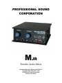
PROFESSIONAL SOUND
CORPORATION
MJR
Portable Audio Mixer
Operation Manual for Mixers with PCB V1.2
Copyright 1999, 2000, 2001, 2002
Professional Sound Corporation
Printed in the U.S.A.
TABLE OF CONTENTS
DESCRIPTION……………………………………………………………………………4
SAFETY WARNINGS……………………………………………………………………4
APPLICATIONS…………………………………………………………………………..4
FUNCTIONS
INPUTS……………………………………………………………………………..5
A.
BALANCED INPUTS
B.
INPUT LEVELS
C.
MICROPHONE POWERING
D.
LOW CUT FILTER
E.
CHANNEL GAIN
F.
CHANNEL PANS
OUTPUTS…………………………………………………………………………...6
MONITOR……………………………………………………………………………6
TAPE RETURNS……………………………………………………………………6
METERS……………………………………………………………………………...7
ADDITIONAL FEATURES………………………………………………………….8
A.
SLATE MICROPHONE
B.
REFERENCE OSCILATOR
2
POWERING…………………………………………………………………………..8
A.
INTERNAL POWER
CONSTRUCTION…………………………………………………………………….9
A.
CHASSIS
B.
ELECTRONIC TOPOLOGY
C.
ENVIRONMENTAL OPERATION
INTERFACING………………………………………………………………………10
A.
TO BETACAMS
B.
TO RDAT RECORDERS
C.
TO WIRELESS MICROPHONES
D.
SPECIAL NOTES
WARRANTY AND NON-WARRANTY SERVICE…………………………………11
SPECIFICATIONS…………………………………………………………………….12
3
DESCRIPTION
Thank you for purchasing the Professional Sound Corporation Mjr Portable Audio
Mixer. PSC is confident that this new Mjr Mixer has set new standards for
portable mixer technologies and features. Please feel free to contact us if you
have any comments or questions concerning your new mixer. Additionally, we
invite you to share your suggestions for new products you would like to see
developed.
Professional Sound Corporation extends a one-year warranty on parts and labor
to all Mjr Mixer owners who return their warranty cards at the time of purchase.
This warranty gives you specific rights, which are stated on the card, and enables
us to keep you informed of product updates.
The PSC Mjr Mixer provides all the functions necessary to produce studio quality
recordings in the field. It’s user friendly features, rugged design and sonic purity
make the Mjr Mixer perfect for electronic news gathering (ENG) electronic field
production (EFP) and feature film production.
HEARING SAFETY WARNINGS:
Please be sure that you have read this entire manual before operating this
mixer.
While special attention has been given to your safety and hearing
protection, the operator determines proper and safe operating levels.
Please note the following:
Always turn down the headphone volume before plugging in your
headphones.
Always operate your headphones at the lowest practical level.
Be especially cautious in unknown or widely varying environments.
Remember, your ears are your livelihood. Turn it down!
APPLICATIONS
•
•
•
•
Electronic News Gathering
Location recording (Dialogue and Music)
Digital Recording and Playback
Broadcast remotes
4
INPUTS:
A.
BALANCED INPUTS
The PSC Mjr Audio Mixer provides two input channels utilizing female XLR
connectors. The professional grade input circuitry is transformer balanced for
improved RF rejection and in-field practicality. The XLR connectors are wired as
follows: Pin 1 shield (ground), Pin 2 Audio high (in phase), Pin 3 Audio low (out of
phase). Balanced wiring enables longer cable runs without the worry of
excessive noise due to nearby electromagnetic and radio frequency interference.
These balanced inputs may be unbalanced if desired. Either pin 2 or 3 may be
tied to ground (pin 1) to unbalance the inputs of the Mjr Mixer. Note: The AES
standard for unbalancing an XLR connector is to tie pin 3 to ground (pin 1).
B.
INPUT LEVELS
The PSC Mjr Mixer can accommodate a wide range in input levels. Microphone
levels of all types can be handled as well as line level signals. The input range of
the Mjr Mixer is –60dBu to +4dBu. Thus the Mjr is compatible with all forms of
consumer and professional audio equipment. The input level switches are
located below and to the right of each input XLR connector. These input level
switches provide for two level settings: “M” Microphone (0dB attenuation), and
“L” Line Level (50dB attenuation) These input level attenuation settings are used
to correctly interface sources of varying levels to the M4mkII’s preamplifiers.
Correct level matching ensures maximum headroom and lowest possible noise
floor.
C.
MICROPHONE POWERING
The Mjr Mixer can accommodate the most popular microphones used today.
The microphone powering switches are located directly below the input XLR
connectors. They can be switched to either Dynamic (D) or 48Phantom (48).
In the Dynamic position the mixer provides no microphone powering. This
position is used with Dynamic Microphones, Line Level inputs and when using
Wireless Receivers.
In the 48 Phantom Position the mixer provides 48 volts DC to power 48PH
microphones or simplex powered microphones with a range of 9 to 52 volts or 12
to 52 volts. Pin 1 is shielded to ground while pins 2 and 3 carry 48 volts DC. The
term “phantom” is derived from the fact that there is no voltage potential
developed across a dynamic microphone transducer that would interfere with its
operation. However, most portable wireless receivers will not operate with 48PH
turned on. We strongly recommend setting inputs to dynamic for use with all
wireless systems.
5
In the interest of keeping the Mjr Mixer design simple and up to date with today’s
technology, we have not offered “12T” or “AB” microphone powering. Although
some “12T” microphones are still in existence, all new microphone designs are
48PH.
D.
LOW CUT FILTERS
Each input channel of the Mjr Mixer is equipped with a HP (high pass) filter.
These filters are activated via the switches located below the adjacent channel
fader knobs. These filters will attenuate all frequencies below 80Hz at a rate of
6dB per octave. High Pass filtering is important in location recording where wind
noise can cause pre-amplifier overload. This effect can be minimized by
switching in the High Pass filter.
E.
CHANNEL GAIN
In order to limit noise and increase headroom, the channel fader controls are
located in the feedback path of the pre-amplifiers. This provides continuously
variable gain rather than just a decrease in channel output level when an
overload situation occurs. This results in increased headroom and lower chance
of signal clipping (severe distortion).
F.
CHANNEL PANS
The new Mjr. Audio Mixer contains front panel mounted pan switches. These
pan switches are used to route the individual input channel’s signal to either the
left or right summing buss. These switches also have center position that allows
audio to be fed to both left and right summing amps.
OUTPUTS:
A.
BALANCED OUTPUT AMPLIFIERS
The Mjr Mixer contains high quality, electronically balanced output circuitry.
These outputs are switchable between line or microphone levels. At the line
level setting, the mixer outputs deliver a nominal 0dBv signal into 10K Ohm
loads. When set to microphone level, the outputs supply –45dBv signal levels.
Please note that 10K Ohm loads are typical of the loads imposed on the mixer by
most Betacams, and other recording devices. Additionally, the Mjr Mixer’s
outputs are capable of driving 600 Ohm loads.
6
B.
MULTI-PIN (BETACAM) CONNECTOR
The Mjr Mixer is equipped with a multi-pin in/out connector designed primarily to
interface with Betacams. This connector provides the left and right balanced
outputs as well as left and right tape returns used for confidence monitoring.
This multi-pin connection provides a convenient means of interfacing to
Betacams with only one connection. In addition, this connection is located on the
back side of the mixer. By locating the connector on the rear of the mixer, all
your cables can be conveniently routed from the rear side of the mixer providing
a clean and compact setup for use on the run.
C.
TRANSCRIPTION OUTPUTS
The Mjr Mixer also contains a dedicated microphone level output used to feed
transcription recorders. This connector is located directly below the main XLR
outputs. It is a 3.5mm Stereo connector wired as follows: Tip = Left, Ring is
Right, Sleeve = Ground. This connector provides a –45dBv signal. This is
compatible with most transcription cassette recorders.
Additionally this
connector can be used to feed audio to consumer and “prosumer” camcorders.
D.
HEADPHONE OUTPUT
The Headphone output is located on the rear panel of the mixer. The Mjr Mixer’s
headphone amplifier circuitry is designed to drive virtually any headphone with an
impedance rating of 32 to 600 Ohms. The headphone volume is controlled by
the use of a rear panel mounted volume control.
*SAFETY NOTE* ALWAYS TURN DOWN THE HEADPHONE VOLUME
BEFORE PLUGGING IN YOUR HEADPHONES.
E.
TAPE RETURN
The Mjr Mixer is equipped with tape returns used to monitor tape confidence
heads from most any recording device. These tape monitor amplifiers can be
adjusted to match the signal levels of most any device. These levels are
adjusted using a small jewelers screwdriver (or “Greenie” screwdriver). The
adjustment points are located on the right hand side of the mixer. The tape/direct
switch is located on the lower right hand corner of the front panel. When set to
”D” (Direct) the phone amplifiers to monitor the mixers output signal. If switched
to “T” (Tape), then the phone amplifies monitor the external source such as the
Betacam.
METERS:
A.
PEAK READING METERS
The Mjr Mixer is equipped with custom made LED meters. We designed these
meters to be easy to read in a variety of light conditions. These meters are peak
reading to allow easy correlation to most modern camera meters. I.E. “0” on the
mixer, equals “0” on the camera. In addition, the LED’s are arranged in a
7
progression of colors from green to yellow to red thus you can easily identify
levels at a quick glance.
ADDITIONAL FEATURES:
A.
SLATE MICROPHONE
The Mjr Mixer is equipped with a slate microphone. This microphone is activated
when the front panel “slate” momentary push button switch is pressed. The slate
microphone allows the operator to put voice slates (notes) on tape for later
reference. These are normally notes for editing tape. A level adjustment trim pot
is located on the bottom panel of the Mjr Mixer. Turning the adjustment
clockwise will increase the slate microphone level. Turning the adjustment
counter-clockwise will lower the level.
B.
REFERENCE OSCILLATOR
The Mjr Mixer is equipped with a reference oscillator used for setting of levels
between the mixer and recorder. This known reference level is also used when
transferring tape during editing. The Mjr’s oscillator operates at 440Hz at “0” on
the meters. When setting up typical Betacams with LCD bar graph meters you
simply adjust the Betacams inputs until “0” is reached. From that point on, you
can monitor levels from the mixer only. We have chosen 440Hz simply because
it is much more pleasant in your headphones than the typical 1Khz used by other
manufactures. We have used 440 Hz on our mixers for many years. The
reference oscillator is equipped with a level adjustment trim pot located inside
mixer. This adjustment is factory calibrated and should not be adjusted without
proper measurement equipment.
C.
BATTERY MONITORING
The Mjr Mixer is equipped with a two LED battery indicator located on the front
panel of the mixer. When the mixer is turned on, the green LED will light when
the battery is in good condition. When the battery needs to be replaced, the
Green LED will switch off and the Red LED will switch on alerting the operator to
replace the battery at his or her earliest convenience.
POWERING:
A. BATTERY POWER
The PSC Mjr Mixer is the first compact ENG mixer with 48 Phantom power to
offer the ability to be powered from a single 9V alkaline battery. This feature
provides a convenient way of powering the mixer without added size or weight.
Only high quality, fresh alkaline 9V batteries should be used to power the Mjr
mixer.
8
The Mjr Mixer consumes approximately 50-60mA of current when no
microphones are being powered. This translates into a battery life of 5 to 10
hours. To remove the battery simply push down on the battery door and pull out
the battery.
Note: Never store your Mjr Mixer for extended periods of time with a battery
installed in the mixer. There is a possibility that the battery may leak
causing corrosion of the mixer.
Battery leakage and the resulting
corrosion damage is not covered under the Mjr Mixer warranty.
CONSTRUCTION
A.
CHASSIS
The new Mjr Mixer chassis has been designed for harsh field use. The complete
chassis is formed from 0.070” aircraft aluminum. All punching is done on a
computer controlled “Strippet” rotary turret punch press for extreme accuracy. In
addition, through careful design, we have managed to keep the overall weight of
the Mjr Mixer to 1.5 lbs. (0.7Kg) total.
The mixers sheet metal is hand-formed using various press brake setups before
the stainless steel threaded inserts are pressed permanently into place. The
housing parts are then Chem Film TM plated for superior corrosion resistance
before being electro-statically coated with an epoxy powder coating. This
powder coat paint is then baked on. Powder coating chosen for its durability and
environmental friendly characteristics.
All silk-screening is printed sub-surface (below) a hardface lexan tm overlay.
This process provides a silk-screened label that is virtually wear proof. The
lettering will not wear off as on other mixers.
B.
ELECTRONIC TOPOLOGY
The new Mjr audio mixer was designed from a clean sheet of paper. It utilizes
completely new circuitry designs based upon the latest advances in semi
conductor technology. In addition, it features surface mount technology for
reduced size and weight.
This new design uses modern semi-conductors from Maxim, Linear Technology
and National Semiconductor to name but a few. These operational amplifiers,
voltage regulators and precision voltage references feature low power
consumption, low noise and low distortion. The also feature ability to swing from
rail to rail resulting in an energy efficient design.
C.
ENVIRONMENTAL OPERATION
Your new Mjr Audio Mixer has been designed to operate under extreme field
conditions. The electronics have been designed to operate over a temperature
range of -4 to 158 degrees Fahrenheit (-20 to +70C) less the affects on batteries.
9
This in addition to the Mjr’s ability to operate under high humidity conditions
makes it perfect for harsh field conditions.
INTERFACING
A.
TO BETACAMS:
The PSC Mjr Mixer is especially designed for easy interfacing with all popular
Betacam type cameras. The Mjr is equipped with a 10 pin Hirose tm connector
on the rear panel. This all-inclusive connector provides both left and right
balanced outputs and tape returns. Pin Outs are as follows:
Pin 1
Pin 2
Pin 3
Pin 4
Pin 5
Pin 6
Pin 7
Pin 8
Pin 9
Pin 10
Left Output High
Left Output Low
Right Output High
Right Output Low
Left Tape Return
Tape Ground
Right Tape Return
Tape Ground
Ground
Ground
PSC manufactures a selection of standard Beta Snake cables for use with the
new Mjr Mixer. Please note that the Mjr Mixer and M4mkII Mixers use the same
cables. These cables are available in standard and camera breakaway versions
from any authorized PSC dealer. Part numbers are as follows:
FPSC1091M4A
FPSC1091M4B
FPSC1091M4C
FPSC1091M4D
B:
15’ (4.5M)
15’ (4.5M)
25’ (7.5M)
25’ (7.5M)
Standard
Breakaway
Standard
Breakaway
TO RDAT RECORDERS:
The M4mkII Mixer can be interfaced to virtually any professional recorder via the
10 pin Hirose tm connector.
If desired, you can also use the tape return
function.
C:
TO WIRELESS MICROPHONES:
The Mjr Mixer will easily accept the output signal from virtually any wireless
receiver. It can accept microphone or line level signal via a simple switch setting.
Please note that most wireless receivers are not compatible with 48PH mic
power. You should always set the Mjr’s mic powering switch to “D” dynamic
when using wireless receivers.
10
The Mjr Mixer can also be used to send audio signals to Betacams via wireless
transmitters. The use of transmitters is normally accomplished by connecting the
Mjr’s 10 pin output connector to the audio input of the specific transmitter. It is
important to note that transmitter placement greatly affects transmit range and
clarity. For best results, transmitters should be mounted away from the mixers
surface allowing un-impeaded RF radiation.
D.
SPECIAL NOTES
The outputs of the Mjr Mixer are electronically balanced and are designed
to drive balanced inputs (loads). To drive unbalanced loads, you should
use only the “Hi” output pin of the mutli-pin connector and the ground pin.
Do not tie the “Low” output pins to ground as you would with other pieces
of equipment. Doing so will not harm the mixer, but it will increase current
consumption, thus shortening you battery life.
WARRANTY AND NON-WARRANTY SERVICE
In the unlikely event your Mjr Mixer requires service it should be carefully packed
and shipped prepaid to:
Professional Sound Corporation
Service Department
28085 Smyth Drive
Valencia, CA 91355 USA
PH 661-295-9395
FAX 661-295-8398
e-mail [email protected]
Please call before shipping your mixer. We may be able to solve your problem
via the phone. Many products have been shipped in to us for service with
incorrect switch settings. We are always willing to help you with your Mjr Mixer
questions.
WARRANTY:
Complete details of the PSC Mjr Mixer warranty are given on the enclosed blue
warranty registration card. If you did not receive one, please contact your local
dealer or call us directly.
11
SPECIFICATIONS
Size:
4.70” x 6.00” x 1.80”
(119mm x 152mm x 46mm)
Weight:
1.5lbs. (0.7Kg)
Temp Range:
-4 to +158F (-20 to +70C)
Batteries:
1x 9V Alkaline
Case Material:
0.070” (2.2mm) Aircraft Aluminum
Finish:
Epoxy Powder Coat
Overlays:
0.005” Hardface Lexan tm with
Sub-surface Epoxy silk screening
Global Gain:
70dB
Freq. Response:
20-20Khz +/-1dB
Signal to Noise:
128.5dB EIN 150 Ohms
Distortion:
00.08% THD
Low Cut Filter:
80Hz, 6dB/Octave
Mic Power:
DYN, 48 PH
Oscillator:
440Hz
Warranty:
1 Year, Limited
Copyright 1999, 2000, 2001, 2002, Professional Sound Corp. This manual and the
complete Mjr Mixer design is covered under various state, federal and
international copyright laws. No portion of this manual or any Mjr mixer
technologies may be reproduced without the specific written permission of PSC.
All rights reserved. This manual and Mjr features and specifications subject to
change without notice.
12