1
INSTALLATION AND
OPERATION MANUAL
RICi-4E1/T1,
RICi-8E1/T1
Fast Ethernet over Four or Eight E1 or T1
NTUs
Version 2.0
The Access Company
RICi-4E1/T1, RICi-8E1/T1
Fast Ethernet over Four or Eight E1 or T1 NTUs
Version 2.0
Installation and Operation Manual
Notice
This manual contains information that is proprietary to RAD Data Communications Ltd. ("RAD").
No part of this publication may be reproduced in any form whatsoever without prior written
approval by RAD Data Communications.
Right, title and interest, all information, copyrights, patents, know-how, trade secrets and other
intellectual property or other proprietary rights relating to this manual and to the RICi-4E1/T1,
RICi-8E1/T1 and any software components contained therein are proprietary products of RAD
protected under international copyright law and shall be and remain solely with RAD.
The RICi-4E1/T1, RICi-8E1/T1 product name is owned by RAD. No right, license, or interest to
such trademark is granted hereunder, and you agree that no such right, license, or interest shall
be asserted by you with respect to such trademark. The RAD name, logo, logotype, and the
terms EtherAccess, TDMoIP and TDMoIP Driven, and the product names Optimux and IPmux, are
registered trademarks of RAD Data Communications Ltd. All other trademarks are the property of
their respective holders.
You shall not copy, reverse compile or reverse assemble all or any portion of the Manual or the
RICi-4E1/T1, RICi-8E1/T1. You are prohibited from, and shall not, directly or indirectly, develop,
market, distribute, license, or sell any product that supports substantially similar functionality as
the RICi-4E1/T1, RICi-8E1/T1, based on or derived in any way from the RICi-4E1/T1, RICi-8E1/T1.
Your undertaking in this paragraph shall survive the termination of this Agreement.
This Agreement is effective upon your opening of the RICi-4E1/T1, RICi-8E1/T1 package and shall
continue until terminated. RAD may terminate this Agreement upon the breach by you of any
term hereof. Upon such termination by RAD, you agree to return to RAD the RICi-4E1/T1, RICi8E1/T1 and all copies and portions thereof.
For further information contact RAD at the address below or contact your local distributor.
International Headquarters
RAD Data Communications Ltd.
North America Headquarters
RAD Data Communications Inc.
24 Raoul Wallenberg Street
Tel Aviv 69719, Israel
Tel: 972-3-6458181
Fax: 972-3-6498250, 6474436
E-mail: [email protected]
900 Corporate Drive
Mahwah, NJ 07430, USA
Tel: (201) 5291100, Toll free: 1-800-4447234
Fax: (201) 5295777
E-mail: [email protected]
© 2004–2008 RAD Data Communications Ltd.
Publication No. 456-200-11/08
Limited Warranty
RAD warrants to DISTRIBUTOR that the hardware in the RICi-4E1/T1, RICi-8E1/T1 to be delivered
hereunder shall be free of defects in material and workmanship under normal use and service for
a period of twelve (12) months following the date of shipment to DISTRIBUTOR.
If, during the warranty period, any component part of the equipment becomes defective by
reason of material or workmanship, and DISTRIBUTOR immediately notifies RAD of such defect,
RAD shall have the option to choose the appropriate corrective action: a) supply a replacement
part, or b) request return of equipment to its plant for repair, or c) perform necessary repair at
the equipment's location. In the event that RAD requests the return of equipment, each party
shall pay one-way shipping costs.
RAD shall be released from all obligations under its warranty in the event that the equipment has
been subjected to misuse, neglect, accident or improper installation, or if repairs or
modifications were made by persons other than RAD's own authorized service personnel, unless
such repairs by others were made with the written consent of RAD.
The above warranty is in lieu of all other warranties, expressed or implied. There are no
warranties which extend beyond the face hereof, including, but not limited to, warranties of
merchantability and fitness for a particular purpose, and in no event shall RAD be liable for
consequential damages.
RAD shall not be liable to any person for any special or indirect damages, including, but not
limited to, lost profits from any cause whatsoever arising from or in any way connected with the
manufacture, sale, handling, repair, maintenance or use of the RICi-4E1/T1, RICi-8E1/T1, and in
no event shall RAD's liability exceed the purchase price of the RICi-4E1/T1, RICi-8E1/T1.
DISTRIBUTOR shall be responsible to its customers for any and all warranties which it makes
relating to RICi-4E1/T1, RICi-8E1/T1 and for ensuring that replacements and other adjustments
required in connection with the said warranties are satisfactory.
Software components in the RICi-4E1/T1, RICi-8E1/T1 are provided "as is" and without warranty
of any kind. RAD disclaims all warranties including the implied warranties of merchantability and
fitness for a particular purpose. RAD shall not be liable for any loss of use, interruption of
business or indirect, special, incidental or consequential damages of any kind. In spite of the
above RAD shall do its best to provide error-free software products and shall offer free Software
updates during the warranty period under this Agreement.
RAD's cumulative liability to you or any other party for any loss or damages resulting from any
claims, demands, or actions arising out of or relating to this Agreement and the RICi-4E1/T1,
RICi-8E1/T1 shall not exceed the sum paid to RAD for the purchase of the RICi-4E1/T1, RICi8E1/T1. In no event shall RAD be liable for any indirect, incidental, consequential, special, or
exemplary damages or lost profits, even if RAD has been advised of the possibility of such
damages.
This Agreement shall be construed and governed in accordance with the laws of the State of
Israel.
Product Disposal
To facilitate the reuse, recycling and other forms of recovery of waste
equipment in protecting the environment, the owner of this RAD product is
required to refrain from disposing of this product as unsorted municipal
waste at the end of its life cycle. Upon termination of the unit’s use,
customers should provide for its collection for reuse, recycling or other form
of environmentally conscientious disposal.
General Safety Instructions
The following instructions serve as a general guide for the safe installation and operation of
telecommunications products. Additional instructions, if applicable, are included inside the
manual.
Safety Symbols
This symbol may appear on the equipment or in the text. It indicates potential
safety hazards regarding product operation or maintenance to operator or service
personnel.
Warning
Danger of electric shock! Avoid any contact with the marked surface while the
product is energized or connected to outdoor telecommunication lines.
Protective ground: the marked lug or terminal should be connected to the building
protective ground bus.
Warning
Some products may be equipped with a laser diode. In such cases, a label with the
laser class and other warnings as applicable will be attached near the optical
transmitter. The laser warning symbol may be also attached.
Please observe the following precautions:
•
Before turning on the equipment, make sure that the fiber optic cable is intact
and is connected to the transmitter.
•
Do not attempt to adjust the laser drive current.
•
Do not use broken or unterminated fiber-optic cables/connectors or look
straight at the laser beam.
•
The use of optical devices with the equipment will increase eye hazard.
•
Use of controls, adjustments or performing procedures other than those
specified herein, may result in hazardous radiation exposure.
ATTENTION: The laser beam may be invisible!
In some cases, the users may insert their own SFP laser transceivers into the product. Users are
alerted that RAD cannot be held responsible for any damage that may result if non-compliant
transceivers are used. In particular, users are warned to use only agency approved products that
comply with the local laser safety regulations for Class 1 laser products.
Always observe standard safety precautions during installation, operation and maintenance of
this product. Only qualified and authorized service personnel should carry out adjustment,
maintenance or repairs to this product. No installation, adjustment, maintenance or repairs
should be performed by either the operator or the user.
Handling Energized Products
General Safety Practices
Do not touch or tamper with the power supply when the power cord is connected. Line voltages
may be present inside certain products even when the power switch (if installed) is in the OFF
position or a fuse is blown. For DC-powered products, although the voltages levels are usually
not hazardous, energy hazards may still exist.
Before working on equipment connected to power lines or telecommunication lines, remove
jewelry or any other metallic object that may come into contact with energized parts.
Unless otherwise specified, all products are intended to be grounded during normal use.
Grounding is provided by connecting the mains plug to a wall socket with a protective ground
terminal. If a ground lug is provided on the product, it should be connected to the protective
ground at all times, by a wire with a diameter of 18 AWG or wider. Rack-mounted equipment
should be mounted only in grounded racks and cabinets.
Always make the ground connection first and disconnect it last. Do not connect
telecommunication cables to ungrounded equipment. Make sure that all other cables are
disconnected before disconnecting the ground.
Some products may have panels secured by thumbscrews with a slotted head. These panels may
cover hazardous circuits or parts, such as power supplies. These thumbscrews should therefore
always be tightened securely with a screwdriver after both initial installation and subsequent
access to the panels.
Connecting AC Mains
Make sure that the electrical installation complies with local codes.
Always connect the AC plug to a wall socket with a protective ground.
The maximum permissible current capability of the branch distribution circuit that supplies power
to the product is 16A. The circuit breaker in the building installation should have high breaking
capacity and must operate at short-circuit current exceeding 35A.
Always connect the power cord first to the equipment and then to the wall socket. If a power
switch is provided in the equipment, set it to the OFF position. If the power cord cannot be
readily disconnected in case of emergency, make sure that a readily accessible circuit breaker or
emergency switch is installed in the building installation.
In cases when the power distribution system is IT type, the switch must disconnect both poles
simultaneously.
Connecting DC Power
Unless otherwise specified in the manual, the DC input to the equipment is floating in reference
to the ground. Any single pole can be externally grounded.
Due to the high current capability of DC power systems, care should be taken when connecting
the DC supply to avoid short-circuits and fire hazards.
DC units should be installed in a restricted access area, i.e. an area where access is authorized
only to qualified service and maintenance personnel.
Make sure that the DC power supply is electrically isolated from any AC source and that the
installation complies with the local codes.
The maximum permissible current capability of the branch distribution circuit that supplies power
to the product is 16A. The circuit breaker in the building installation should have high breaking
capacity and must operate at short-circuit current exceeding 35A.
Before connecting the DC supply wires, ensure that power is removed from the DC circuit. Locate
the circuit breaker of the panel board that services the equipment and switch it to the OFF
position. When connecting the DC supply wires, first connect the ground wire to the
corresponding terminal, then the positive pole and last the negative pole. Switch the circuit
breaker back to the ON position.
A readily accessible disconnect device that is suitably rated and approved should be incorporated
in the building installation.
If the DC power supply is floating, the switch must disconnect both poles simultaneously.
Connecting Data and Telecommunications Cables
Data and telecommunication interfaces are classified according to their safety status.
The following table lists the status of several standard interfaces. If the status of a given port
differs from the standard one, a notice will be given in the manual.
Ports
Safety Status
V.11, V.28, V.35, V.36, RS-530, X.21,
10 BaseT, 100 BaseT, Unbalanced E1,
E2, E3, STM, DS-2, DS-3, S-Interface
ISDN, Analog voice E&M
SELV
xDSL (without feeding voltage),
Balanced E1, T1, Sub E1/T1
TNV-1 Telecommunication Network Voltage-1:
FXS (Foreign Exchange Subscriber)
TNV-2 Telecommunication Network Voltage-2:
Ports whose normal operating voltage exceeds the
limits of SELV (usually up to 120 VDC or telephone
ringing voltages), on which overvoltages from
telecommunication networks are not possible. These
ports are not permitted to be directly connected to
external telephone and data lines.
FXO (Foreign Exchange Office), xDSL
(with feeding voltage), U-Interface
ISDN
TNV-3 Telecommunication Network Voltage-3:
Ports whose normal operating voltage exceeds the
limits of SELV (usually up to 120 VDC or telephone
ringing voltages), on which overvoltages from
telecommunication networks are possible.
Safety Extra Low Voltage:
Ports which do not present a safety hazard. Usually
up to 30 VAC or 60 VDC.
Ports whose normal operating voltage is within the
limits of SELV, on which overvoltages from
telecommunications networks are possible.
Always connect a given port to a port of the same safety status. If in doubt, seek the assistance
of a qualified safety engineer.
Always make sure that the equipment is grounded before connecting telecommunication cables.
Do not disconnect the ground connection before disconnecting all telecommunications cables.
Some SELV and non-SELV circuits use the same connectors. Use caution when connecting cables.
Extra caution should be exercised during thunderstorms.
When using shielded or coaxial cables, verify that there is a good ground connection at both
ends. The grounding and bonding of the ground connections should comply with the local codes.
The telecommunication wiring in the building may be damaged or present a fire hazard in case of
contact between exposed external wires and the AC power lines. In order to reduce the risk,
there are restrictions on the diameter of wires in the telecom cables, between the equipment
and the mating connectors.
Caution
To reduce the risk of fire, use only No. 26 AWG or larger telecommunication line
cords.
Attention
Pour réduire les risques s’incendie, utiliser seulement des conducteurs de
télécommunications 26 AWG ou de section supérieure.
Some ports are suitable for connection to intra-building or non-exposed wiring or cabling only. In
such cases, a notice will be given in the installation instructions.
Do not attempt to tamper with any carrier-provided equipment or connection hardware.
Electromagnetic Compatibility (EMC)
The equipment is designed and approved to comply with the electromagnetic regulations of
major regulatory bodies. The following instructions may enhance the performance of the
equipment and will provide better protection against excessive emission and better immunity
against disturbances.
A good ground connection is essential. When installing the equipment in a rack, make sure to
remove all traces of paint from the mounting points. Use suitable lock-washers and torque. If an
external grounding lug is provided, connect it to the ground bus using braided wire as short as
possible.
The equipment is designed to comply with EMC requirements when connecting it with unshielded
twisted pair (UTP) cables. However, the use of shielded wires is always recommended, especially
for high-rate data. In some cases, when unshielded wires are used, ferrite cores should be
installed on certain cables. In such cases, special instructions are provided in the manual.
Disconnect all wires which are not in permanent use, such as cables used for one-time
configuration.
The compliance of the equipment with the regulations for conducted emission on the data lines
is dependent on the cable quality. The emission is tested for UTP with 80 dB longitudinal
conversion loss (LCL).
Unless otherwise specified or described in the manual, TNV-1 and TNV-3 ports provide secondary
protection against surges on the data lines. Primary protectors should be provided in the building
installation.
The equipment is designed to provide adequate protection against electro-static discharge (ESD).
However, it is good working practice to use caution when connecting cables terminated with
plastic connectors (without a grounded metal hood, such as flat cables) to sensitive data lines.
Before connecting such cables, discharge yourself by touching ground or wear an ESD preventive
wrist strap.
FCC-15 User Information
This equipment has been tested and found to comply with the limits of the Class A digital device,
pursuant to Part 15 of the FCC rules. These limits are designed to provide reasonable protection
against harmful interference when the equipment is operated in a commercial environment. This
equipment generates, uses and can radiate radio frequency energy and, if not installed and used
in accordance with the Installation and Operation manual, may cause harmful interference to the
radio communications. Operation of this equipment in a residential area is likely to cause harmful
interference in which case the user will be required to correct the interference at his own
expense.
Canadian Emission Requirements
This Class A digital apparatus meets all the requirements of the Canadian Interference-Causing
Equipment Regulation.
Cet appareil numérique de la classe A respecte toutes les exigences du Règlement sur le matériel
brouilleur du Canada.
Warning per EN 55022 (CISPR-22)
Warning
Avertissement
Achtung
This is a class A product. In a domestic environment, this product may cause radio
interference, in which case the user will be required to take adequate measures.
Cet appareil est un appareil de Classe A. Dans un environnement résidentiel, cet
appareil peut provoquer des brouillages radioélectriques. Dans ces cas, il peut être
demandé à l’utilisateur de prendre les mesures appropriées.
Das vorliegende Gerät fällt unter die Funkstörgrenzwertklasse A. In Wohngebieten
können beim Betrieb dieses Gerätes Rundfunkströrungen auftreten, für deren
Behebung der Benutzer verantwortlich ist.
Français
Mise au rebut du produit
Afin de faciliter la réutilisation, le recyclage ainsi que d'autres formes de
récupération d'équipement mis au rebut dans le cadre de la protection de
l'environnement, il est demandé au propriétaire de ce produit RAD de ne pas
mettre ce dernier au rebut en tant que déchet municipal non trié, une fois
que le produit est arrivé en fin de cycle de vie. Le client devrait proposer des
solutions de réutilisation, de recyclage ou toute autre forme de mise au rebut
de cette unité dans un esprit de protection de l'environnement, lorsqu'il aura
fini de l'utiliser.
Instructions générales de sécurité
Les instructions suivantes servent de guide général d'installation et d'opération sécurisées des
produits de télécommunications. Des instructions supplémentaires sont éventuellement
indiquées dans le manuel.
Symboles de sécurité
Ce symbole peut apparaitre sur l'équipement ou dans le texte. Il indique des risques
potentiels de sécurité pour l'opérateur ou le personnel de service, quant à
l'opération du produit ou à sa maintenance.
Avertissement
Danger de choc électrique ! Evitez tout contact avec la surface marquée tant que le
produit est sous tension ou connecté à des lignes externes de télécommunications.
Mise à la terre de protection : la cosse ou la borne marquée devrait être connectée
à la prise de terre de protection du bâtiment.
•
Avant la mise en marche de l'équipement, assurez-vous que le câble de fibre
optique est intact et qu'il est connecté au transmetteur.
•
Ne tentez pas d'ajuster le courant de la commande laser.
•
N'utilisez pas des câbles ou connecteurs de fibre optique cassés ou sans
terminaison et n'observez pas directement un rayon laser.
•
L'usage de périphériques optiques avec l'équipement augmentera le risque pour
les yeux.
•
L'usage de contrôles, ajustages ou procédures autres que celles spécifiées ici
pourrait résulter en une dangereuse exposition aux radiations.
ATTENTION : Le rayon laser peut être invisible !
Les utilisateurs pourront, dans certains cas, insérer leurs propres émetteurs-récepteurs Laser SFP
dans le produit. Les utilisateurs sont avertis que RAD ne pourra pas être tenue responsable de
tout dommage pouvant résulter de l'utilisation d'émetteurs-récepteurs non conformes. Plus
particulièrement, les utilisateurs sont avertis de n'utiliser que des produits approuvés par
l'agence et conformes à la réglementation locale de sécurité laser pour les produits laser de
classe 1.
Respectez toujours les précautions standards de sécurité durant l'installation, l'opération et la
maintenance de ce produit. Seul le personnel de service qualifié et autorisé devrait effectuer
l'ajustage, la maintenance ou les réparations de ce produit. Aucune opération d'installation,
d'ajustage, de maintenance ou de réparation ne devrait être effectuée par l'opérateur ou
l'utilisateur.
Manipuler des produits sous tension
Règles générales de sécurité
Ne pas toucher ou altérer l'alimentation en courant lorsque le câble d'alimentation est branché.
Des tensions de lignes peuvent être présentes dans certains produits, même lorsque le
commutateur (s'il est installé) est en position OFF ou si le fusible est rompu. Pour les produits
alimentés par CC, les niveaux de tension ne sont généralement pas dangereux mais des risques
de courant peuvent toujours exister.
Avant de travailler sur un équipement connecté aux lignes de tension ou de télécommunications,
retirez vos bijoux ou tout autre objet métallique pouvant venir en contact avec les pièces sous
tension.
Sauf s'il en est autrement indiqué, tous les produits sont destinés à être mis à la terre durant
l'usage normal. La mise à la terre est fournie par la connexion de la fiche principale à une prise
murale équipée d'une borne protectrice de mise à la terre. Si une cosse de mise à la terre est
fournie avec le produit, elle devrait être connectée à tout moment à une mise à la terre de
protection par un conducteur de diamètre 18 AWG ou plus. L'équipement monté en châssis ne
devrait être monté que sur des châssis et dans des armoires mises à la terre.
Branchez toujours la mise à la terre en premier et débranchez-la en dernier. Ne branchez pas des
câbles de télécommunications à un équipement qui n'est pas mis à la terre. Assurez-vous que
tous les autres câbles sont débranchés avant de déconnecter la mise à la terre.
Français
Certains produits peuvent être équipés d'une diode laser. Dans de tels cas, une
étiquette indiquant la classe laser ainsi que d'autres avertissements, le cas échéant,
sera jointe près du transmetteur optique. Le symbole d'avertissement laser peut
aussi être joint.
Avertissement
Veuillez observer les précautions suivantes :
Français
Connexion au courant du secteur
Assurez-vous que l'installation électrique est conforme à la réglementation locale.
Branchez toujours la fiche de secteur à une prise murale équipée d'une borne protectrice de mise
à la terre.
La capacité maximale permissible en courant du circuit de distribution de la connexion alimentant
le produit est de 16A. Le coupe-circuit dans l'installation du bâtiment devrait avoir une capacité
élevée de rupture et devrait fonctionner sur courant de court-circuit dépassant 35A.
Branchez toujours le câble d'alimentation en premier à l'équipement puis à la prise murale. Si un
commutateur est fourni avec l'équipement, fixez-le en position OFF. Si le câble d'alimentation ne
peut pas être facilement débranché en cas d'urgence, assurez-vous qu'un coupe-circuit ou un
disjoncteur d'urgence facilement accessible est installé dans l'installation du bâtiment.
Le disjoncteur devrait déconnecter simultanément les deux pôles si le système de distribution de
courant est de type IT.
Connexion d'alimentation CC
Sauf s'il en est autrement spécifié dans le manuel, l'entrée CC de l'équipement est flottante par
rapport à la mise à la terre. Tout pôle doit être mis à la terre en externe.
A cause de la capacité de courant des systèmes à alimentation CC, des précautions devraient
être prises lors de la connexion de l'alimentation CC pour éviter des courts-circuits et des risques
d'incendie.
Les unités CC devraient être installées dans une zone à accès restreint, une zone où l'accès n'est
autorisé qu'au personnel qualifié de service et de maintenance.
Assurez-vous que l'alimentation CC est isolée de toute source de courant CA (secteur) et que
l'installation est conforme à la réglementation locale.
La capacité maximale permissible en courant du circuit de distribution de la connexion alimentant
le produit est de 16A. Le coupe-circuit dans l'installation du bâtiment devrait avoir une capacité
élevée de rupture et devrait fonctionner sur courant de court-circuit dépassant 35A.
Avant la connexion des câbles d'alimentation en courant CC, assurez-vous que le circuit CC n'est
pas sous tension. Localisez le coupe-circuit dans le tableau desservant l'équipement et fixez-le
en position OFF. Lors de la connexion de câbles d'alimentation CC, connectez d'abord le
conducteur de mise à la terre à la borne correspondante, puis le pôle positif et en dernier, le
pôle négatif. Remettez le coupe-circuit en position ON.
Un disjoncteur facilement accessible, adapté et approuvé devrait être intégré à l'installation du
bâtiment.
Le disjoncteur devrait déconnecter simultanément les deux pôles si l'alimentation en courant CC
est flottante.
Declaration of Conformity
Manufacturer's Name:
RAD Data Communications Ltd.
Manufacturer's Address:
24 Raoul Wallenberg St., Tel Aviv 69719, Israel
declares that the product:
Product Name:
RICi-8E1, RICi-4E1
conforms to the following standard(s) or other normative document(s):
EMC:
Safety:
EN 55022:1998 +
A1:2000, A2:2003
Information technology equipment – Radio
disturbance characteristics – Limits and
methods of measurement.
EN 55024:1998 +
A1:2001, A2:2003
Information technology equipment – Immunity
characteristics – Limits and methods of
measurement.
EN 60950-1:2001
Information technology equipment – Safety –
Part 1: General requirements.
Supplementary Information:
The products herewith comply with the requirements of the EMC Directive 89/336/EEC, the Low
Voltage Directive 73/23/EEC and the R&TTE Directive 99/5/EC for wired equipment. The products
were tested in a typical configuration.
Tel Aviv, 7 November 2006
Haim Karshen
VP Quality
European Contact: RAD Data Communications GmbH, Otto-Hahn-Str. 28-30, 85521
Ottobrunn-Riemerling, Germany
Glossary
Address
A coded representation of the origin or destination of data.
Agent
In SNMP, this refers to the managed system.
Analog
A continuous wave or signal (such as human voice).
ANSI
American National Standards Institute.
AWG
The American Wire Gauge System, which specifies wire width.
Backhaul
Transporting traffic between distributed sites (typically access
points) and more centralized points of presence. See Cellular
Backhaul.
Balanced
A transmission line in which voltages on the two conductors are
equal in magnitude, but opposite in polarity, with respect to
ground.
Bandwidth
The range of frequencies passing through a given circuit. The
greater the bandwidth, the more information can be sent through
the circuit in a given amount of time.
Baud
Unit of signaling speed equivalent to the number of discrete
conditions or events per second. If each signal event represents
only one bit condition, baud rate equals bps (bits per second).
Bit
The smallest unit of information in a binary system. Represents
either a one or zero (“1” or “0”).
bps (Bits Per Second)
A measure of data transmission rate in serial transmission.
Bridge
A device interconnecting local area networks at the OSI data link
layer, filtering and forwarding frames according to media access
control (MAC) addresses.
Buffer
A storage device. Commonly used to compensate for differences
in data rates or event timing when transmitting from one device to
another. Also used to remove jitter.
Bus
A transmission path or channel. A bus is typically an electrical
connection with one or more conductors, where all attached
devices receive all transmissions at the same time.
Byte
A group of bits (normally 8 bits in length).
Carrier
A continuous signal at a fixed frequency that is capable of being
modulated with a second (information carrying) signal.
Cell
The 53-byte basic information unit within an ATM network. The
user traffic is segmented into cells at the source and reassembled
at the destination. An ATM cell consists of a 5-byte ATM header
and a 48-byte ATM payload, which contains the user data.
Channel
A path for electrical transmission between two or more points.
Also called a link, line, circuit or facility.
Clock
A term for the source(s) of timing signals used in synchronous
transmission.
Compression
Any of several techniques that reduce the number of bits required
to represent information in data transmission or storage, thereby
conserving bandwidth and/or memory.
Congestion
A state in which the network is overloaded and starts to discard
user data (frames, cells or packets).
Data
Information represented in digital form, including voice, text,
facsimile and video.
Data Link Layer
Layer 2 of the OSI model. The entity, which establishes, maintains,
and releases data-link connections between elements in a
network. Layer 2 is concerned with the transmission of units of
information, or frames, and associated error checking.
Diagnostics
The detection and isolation of a malfunction or mistake in a
communications device, network or system.
Digital
The binary (“1” or “0”) output of a computer or terminal. In data
communications, an alternating, non-continuous (pulsating) signal.
E1 Line
A 2.048 Mbps line, common in Europe, that supports thirty-two 64
kbps channels, each of which can transmit and receive data or
digitized voice. The line uses framing and signaling to achieve
synchronous and reliable transmission. The most common
configurations for E1 lines are E1 PRI, and unchannelized E1.
E3
The European standard for high speed digital transmission,
operating at 34 Mbps.
Encapsulation
Encapsulating data is a technique used by layered protocols in
which a low level protocol accepts a message from a higher level
protocol, then places it in the data portion of the lower-level
frame. The logistics of encapsulation require that packets traveling
over a physical network contain a sequence of headers.
Equalizer
A device that compensates for distortion due to signal attenuation
and propagation time with respect to frequency. It reduces the
effects of amplitude, frequency and/or phase distortion.
Ethernet
A local area network (LAN) technology which has extended into
the wide area networks. Ethernet operates at many speeds,
including data rates of 10 Mbps (Ethernet), 100 Mbps (Fast
Ethernet), 1,000 Mbps (Gigabit Ethernet), 10 Gbps, 40 Gbps, and
100 Gbps.
Ethernet OAM
Ethernet operation, administration and maintenance (OAM) are a
set of standardized protocols for measuring and controlling
network performance. There are two layers of Ethernet OAM:
Service OAM (provides end-to-end connectivity fault management
per customer service instance, even in multi-operator networks)
and Link or Segment OAM (detailed monitoring and
troubleshooting of an individual physical or emulated link).
Flow Control
A congestion control mechanism that results in an ATM system
implementing flow control.
Frame
A logical grouping of information sent as a link-layer unit over a
transmission medium. The terms packet, datagram, segment, and
message are also used to describe logical information groupings.
Framing
At the physical and data link layers of the OSI model, bits are fit
into units called frames. Frames contain source and destination
information, flags to designate the start and end of the frame,
plus information about the integrity of the frame. All other
information, such as network protocols and the actual payload of
data, is encapsulated in a packet, which is encapsulated in the
frame.
Full Duplex
A circuit or device permitting transmission in two directions
(sending and receiving) at the same time.
FXO (Foreign Exchange
Office)
A voice interface, emulating a PBX extension, as it appears to the
CO (Central Office) for connecting a PBX extension to a
multiplexer.
FXS (Foreign Exchange
Subscriber)
A voice interface, emulating the extension interface of a PBX (or
subscriber interface of a CO) for connecting a regular telephone
set to a multiplexer.
G.703
An ITU standard for the physical and electrical characteristics of
various digital interfaces, including those at 64 kbps and 2.048
Mbps.
Gateway
Gateways are points of entrance and exit from a communications
network. Viewed as a physical entity, a gateway is that node that
translates between two otherwise incompatible networks or
network segments. Gateways perform code and protocol
conversion to facilitate traffic between data highways of differing
architecture.
Half Duplex
A circuit or device capable of transmitting in two directions, but
not at the same time.
Interface
A shared boundary, defined by common physical interconnection
characteristics, signal characteristics, and meanings of exchanged
signals.
IP Address
Also known as an Internet address. A unique string of numbers
that identifies a computer or device on a TCP/IP network. The
format of an IP address is a 32-bit numeric address written as four
numbers from 0 to 255, separated by periods (for example,
1.0.255.123).
Jitter
The deviation of a transmission signal in time or phase. It can
introduce errors and loss of synchronization in high speed
synchronous communications.
Laser
A device that transmits an extremely narrow and coherent beam
of electromagnetic energy in the visible light spectrum. Used as a
light source for fiber optic transmission (generally more expensive,
shorter lived, single mode only, for greater distances than LED).
Loop Start
The most commonly used method of signaling an off-hook
condition between an analog phone set and a switch, where
picking up the receiver closes a wire loop, allowing DC current to
flow, which is detected by a PBX or local exchange and interpreted
as a request for service.
Loopback
A type of diagnostic test in which the transmitted signal is
returned to the sending device after passing through all or part of
a communications link or network.
Manager
An application that receives Simple Network Management Protocol
(SNMP) information from an agent. An agent and manager share a
database of information, called the Management Information Base
(MIB). An agent can use a message called a traps-PDU to send
unsolicited information to the manager. A manager that uses the
RADview MIB can query the RAD device, set parameters, sound
alarms when certain conditions appear, and perform other
administrative tasks.
Master Clock
The source of timing signals (or the signals themselves) that all
network stations use for synchronization.
Multiplexer
At one end of a communications link, a device that combines
several lower speed transmission channels into a single high speed
channel. A multiplexer at the other end reverses the process.
Sometimes called a mux. See Bit Interleaving/Multiplexing.
Network
(1) An interconnected group of nodes. (2) A series of points,
nodes, or stations connected by communications channels; the
collection of equipment through which connections are made
between data stations.
Node
A point of interconnection to a network.
Off-Hook
A state that results when you lift a telephone receiver, producing a
busy signal.
Packet
An ordered group of data and control signals transmitted through
a network, as a subset of a larger message.
Payload
The 48-byte segment of the ATM cell containing user data. Any
adaptation of user data via the AAL will take place within the
payload.
Physical Layer
Layer 1 of the OSI model. The layer concerned with electrical,
mechanical, and handshaking procedures over the interface
connecting a device to the transmission medium.
Polling
See Multidrop.
Port
The physical interface to a computer or multiplexer, for connection
of terminals and modems.
Protocol
A formal set of conventions governing the formatting and relative
timing of message exchange between two communicating
systems.
Serial Transmission
A common mode of transmission, where the character bits are
sent sequentially one at a time instead of in parallel.
Single Mode
Describing an optical wave-guide or fiber that is designed to
propagate light of only a single wavelength (typically 5-10 microns
in diameter).
Space
In telecommunications, the absence of a signal. Equivalent to a
binary 0.
Sync
See Synchronous Transmission.
Synchronous
Transmission
Transmission in which data bits are sent at a fixed rate, with the
transmitter and receiver synchronized.
T1
A digital transmission link with a capacity of 1.544 Mbps used in
North America. Typically channelized into 24 DS0s, each capable of
carrying a single voice conversation or data stream. Uses two pairs
of twisted pair wires.
T3
A digital transmission link with a capacity of 45 Mbps, or 28 T1
lines.
Telnet
The virtual terminal protocol in the Internet suite of protocols. It
lets users on one host access another host and work as terminal
users of that remote host. Instead of dialing into the computer,
the user connects to it over the Internet using Telnet. When
issuing a Telnet session, it connects to the Telnet host and logs in.
The connection enables the user to work with the remote machine
as though a terminal was connected to it.
VLAN-Aware
A device that is doing the Layer 2 bridging according to the VLAN
tag in addition to the standard bridging parameters. A VLAN-aware
device will not strip or add any VLAN header.
VLAN Stacking
A technique that lets carriers offer multiple virtual LANs over a
single circuit. In essence, the carrier creates an Ethernet virtual
private network to tunnel customer VLANs across its WAN; this
helps avoid name conflicts among customers of service providers
who connect to the carrier. Stacking works by assigning two VLAN
IDs to each frame header. One is a "backbone" VLAN ID used by
the service provider; the other one has up to 4,096 unique 802.1Q
VLAN tags.
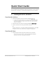
Quick Start Guide
Your unit should only be installed by an experienced technician. If you are familiar
with RICi-4E1/T1, RICi-8E1/T1, use this guide to prepare the units for operation.
1.
Installing RICi-4E1/T1, RICi-8E1/T1
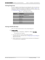
Connecting the Interfaces
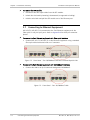
1. Connect the network to the RJ-45 connector designated E1 or T1.
In case of fiber optical interfaces, first insert the SFP and then connect
the Ethernet equipment using a standard fiber optic cable terminated
with an LC connector.
2. Connect the user LAN to the RJ-45 connector designated 10/100 BaseT.
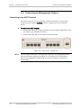
3. Connect a terminal to the front panel CONTROL connector
OR
Connect a Telnet host, a PC running a Web browsing application, or an SNMP
management station to the Ethernet port assigned to management.
Connecting the Power
•
Connect the power cable to the power connector on the rear panel.
The unit has no power switch. It starts operating when the power
connector at the rear is connected to the mains.
RICi-4E1/T1, RICi-8E1/T1 Ver. 2.0
Installing RICi-4E1/T1, RICi-8E1/T1
1
Quick Start Guide
RICi-4E1/T1, RICi-8E1/T1 Installation and Operation Manual
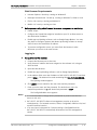
2.
Configuring RICi-4E1/T1, RICi-8E1/T1
Configure RICi-4E1/T1, RICi-8E1/T1 to the desired operation mode via an ASCII
terminal connected to the front panel CONTROL port. After configuring, you can
manage the unit over Telnet, a PC running a Web browsing application, or SNMP
via either the Ethernet or E1 port.
Note
Remote management requires assigning an IP address.
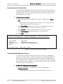
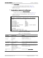
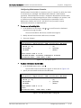
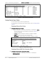
Starting a Terminal Session for the First Time
For first use, you have to use an ASCII terminal to configure
RICi-4E1/T1, RICi-8E1/T1.
³
To start a terminal session:
1. If not already done, connect a terminal to the CONTROL connector.
2. Turn on the control terminal PC and set its default port parameters to a baud
rate of 115,200 bps, 8 data, 1 stop bit and no parity.
3. Set the terminal emulator to ANSI VT100 emulation (to ensure an optimal
view of system menus).
4. Set the terminal screen width to 132 characters.
5. Enter your user name and password and proceed with the management
session.
Note
The default user name is su, and the default password is 1234.
Configuring the IP Management Parameters
You have to configure the IP address, the subnet mask, and the default gateway.
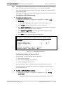
³
To configure IP management parameters:
•
2
Navigate to the Host IP menu (Main > Configuration > System > Management
> Host IP) and configure the required IP host parameters.
Configuring RICi-4E1/T1, RICi-8E1/T1
RICi-4E1/T1, RICi-8E1/T1 Ver. 2.0
RICi-4E1/T1, RICi-8E1/T1 Installation and Operation Manual
Quick Start Guide
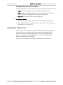
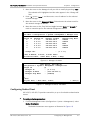
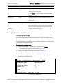
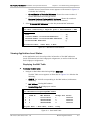
Configuring Ports at the Physical Level
You have to first configure the ports at the physical level.
³
To configure the Fast Ethernet ports:
1. From the Physical Ports menu (Main > Configuration > Physical Ports), go to
Activation and activate or deactivate the ports as needed.
2. Disable or enable Auto Negotiation, Flow Control and MDIX Auto Cross Over
as needed.
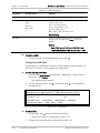
³
To configure E1/T1 ports:
1. From the Physical Port menu (Main > Configuration > Physical Port), choose
the port type.
2. Under Activation, activate or deactivate the port as needed.
3. Configure the required parameters associated with the relevant port.
Configuring the Bridge
The bridge parameters, as well as the bridge ports and the VLAN memberships,
must be configured according to your application requirements.
³
To configure the bridge:
•
³
To configure the bridge ports:
•
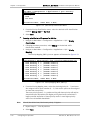
³
From the Bridge menu (Main > Configuration > Applications > Bridge),
configure the VLAN and filtering modes of the RICi-4E1/T1, RICi-8E1/T1
bridges.
From the Bridge Port menu (Configuration> Applications > Bridge > Bridge
Port), select a bridge port and configure the necessary parameters.
To configure the VLAN memberships:
•
From the VLAN Membership menu (Configuration > Applications > Bridge >
VLAN Membership), create a new VLAN and define the egress tagged and
untagged ports which are the VLAN members.
RICi-4E1/T1, RICi-8E1/T1 Ver. 2.0
Configuring RICi-4E1/T1, RICi-8E1/T1
3
Quick Start Guide
RICi-4E1/T1, RICi-8E1/T1 Installation and Operation Manual
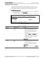
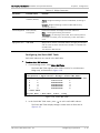
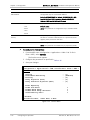
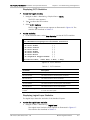
Configuring the QoS
In order to prioritize the traffic, you have to choose a priority classification
method and assign priorities to the traffic queues according to the selected
method.
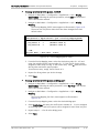
³
To select a priority classification method:
•
³
To assign priorities to the traffic queues:
•
4
From the QoS menu (Main > Configuration > Applications > QoS), select
Priority Classification and choose the desired traffic classification method:
802.1p, DSCP or Per Port.
From the Priority Mapping menu (Main > Configuration > Applications > QoS),
select Priority Mapping and assign priorities to the traffic queues according to
the selected method.
Configuring RICi-4E1/T1, RICi-8E1/T1
RICi-4E1/T1, RICi-8E1/T1 Ver. 2.0
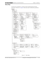
Contents
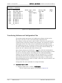
Chapter 1. Introduction 1.1 Overview.................................................................................................................... 1-1 Product Options...................................................................................................... 1-1 Applications ............................................................................................................ 1-2 Features ................................................................................................................. 1-2 1.2 Physical Description ................................................................................................... 1-6 1.3 Functional Description................................................................................................ 1-7 Bridge..................................................................................................................... 1-7 Quality of Service.................................................................................................. 1-14 Management ........................................................................................................ 1-15 1.4 Technical Specifications............................................................................................ 1-16 General................................................................................................................. 1-16 Interfaces ............................................................................................................. 1-17 Chapter 2. Installation and Setup 2.1 2.2 2.3 2.4 2.5 2.6 2.7 2.8 2.9 Introduction ............................................................................................................... 2-1 Site Requirements and Prerequisites .......................................................................... 2-1 Package Contents ...................................................................................................... 2-2 Required Equipment ................................................................................................... 2-2 Mounting the Unit ...................................................................................................... 2-3 Installing Fiber Optic SFP Modules .............................................................................. 2-3 Connecting to Ethernet Equipment ............................................................................. 2-4 Connecting to E1/T1 Equipment ................................................................................. 2-5 Connecting to Management Stations .......................................................................... 2-6 Connecting to an ASCII Terminal .............................................................................. 2-6 2.10 Connecting to Power .................................................................................................. 2-7 Connecting AC Power .............................................................................................. 2-7 Connecting DC Power.............................................................................................. 2-7 Chapter 3. Operation 3.1 3.2 3.3 3.4 Turning On the Unit ................................................................................................... 3-1 Indicators .................................................................................................................. 3-2 Default Settings ......................................................................................................... 3-4 Configuration and Management Alternatives .............................................................. 3-8 Working with an ASCII Terminal ............................................................................... 3-8 Working with Web Terminal................................................................................... 3-10 Working with RADview-Lite ................................................................................... 3-12 Menu Map ............................................................................................................ 3-13 3.5 Turning Off the Unit ................................................................................................. 3-14 Chapter 4. Configuration 4.1 Configuring for Management ...................................................................................... 4-1 Defining Host IP Parameters ................................................................................... 4-2 Entering Device Information .................................................................................... 4-4 Controlling Management Access .............................................................................. 4-4 Configuring User Access .......................................................................................... 4-5 Configuring Network Managers ............................................................................... 4-6 RICi-4E1/T1 and RICi-8E1/T1 Ver. 2.0
i
Table of Contents
Installation and Operation Manual
Configuring Radius Client ........................................................................................ 4-7 Defining the Access Policy....................................................................................... 4-9 Configuring Control Port Parameters ..................................................................... 4-10 4.2 Configuring for Operation ........................................................................................ 4-10 Setting Device-Level Parameters ........................................................................... 4-10 Setting Physical Layer Parameters ......................................................................... 4-12 Setting Logical Layer Parameters ........................................................................... 4-17 Setting Application-Level Parameters .................................................................... 4-18 4.3 Additional Tasks ....................................................................................................... 4-34 Configuring Date and Time .................................................................................... 4-34 Configuring the Syslog Parameters ........................................................................ 4-35 Viewing Inventory ................................................................................................. 4-37 Transferring Software and Configuration Files ....................................................... 4-38 Resetting RICi-4E1/T1, RICi-8E1/T1 ........................................................................ 4-39 Chapter 5. Configuring a Typical Application 5.1 Application Requirements........................................................................................... 5-1 5.2 Configuring the Management Parameters ................................................................... 5-2 Defining the Host ................................................................................................... 5-2 Defining the Default Gateway ................................................................................. 5-2 Defining Managers .................................................................................................. 5-3 5.3 Configuring E1/T1 Physical Layer ................................................................................ 5-4 5.4 Configuring the Bridge ............................................................................................... 5-4 Defining the Bridge ................................................................................................. 5-4 Defining Bridge Ports .............................................................................................. 5-5 Defining VLAN Memberships ................................................................................... 5-5 Chapter 6. Troubleshooting and Diagnostics 6.1 Monitoring Performance ............................................................................................. 6-1 Viewing System Status Information ......................................................................... 6-1 Viewing Physical Layer Status .................................................................................. 6-2 Viewing Application-Level Status ............................................................................. 6-3 Viewing Interface Statistics ..................................................................................... 6-4 6.2 Handling Alarms and Traps ......................................................................................... 6-6 Displaying Events .................................................................................................... 6-6 Clearing Events ....................................................................................................... 6-7 Traps Generated by RICi-4E1/T1, RICi-8E1/T1 .......................................................... 6-8 6.3 Troubleshooting ......................................................................................................... 6-9 6.4 Testing the Unit ....................................................................................................... 6-10 Running a Ping Test .............................................................................................. 6-10 Tracing the Route ................................................................................................. 6-10 Performing a Loopback Test on E1/T1 Links .......................................................... 6-11 Performing Bit Error Rate Test (BERT).................................................................... 6-12 Running OAM Tests............................................................................................... 6-13 6.5 Technical Support .................................................................................................... 6-20 Appendix A. Connector Wiring Appendix B. Boot Sequence and Downloading Software ii
RICi-4E1/T1 and RICi-8E1/T1 Ver. 2.0
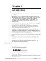
Chapter 1
Introduction
1.1
Overview
RICi-4E1/T1, RICi-8E1/T1 is a Network Termination Unit (NTU) connecting Fast
Ethernet LANs over four or eight E1 or T1 circuits. RICi-4E1/T1, RICi-8E1/T1 is part
of RAD’s RICi product family. It enables service provisioning and backhaul
applications over low- and high-speed SDH/SONET and PDH circuits, from
fractional and full E1/T1 and E3/T3 over STM-1/OC-3 and STM-4/OC-12 to
Ethernet networks.
RICi-4E1/T1, RICi-8E1/T1 can bond four or eight E1 or T1 ports together using
Multilink PPP (MLPPP), creating a large virtual pipe.
RICi-4E1/T1, RICi-8E1/T1 provides Layer-2 switching (bridge) between the
Ethernet ports and the E1/T1 port, including VLAN-unaware and VLAN-aware
bridging modes supporting VLAN based Layer-2 VPNs.
Depending on the hardware configuration, RICi-4E1/T1, RICi-8E1/T1 provides
4 x 10/100BaseT or 2 x 10/100BaseT and 2 x SFP-based 100BaseFx Fast Ethernet
ports. In the 4 x 10/100BaseT configuration, you may use one Ethernet port for
out-of-band management. In addition, RICi-4E1/T1, RICi-8E1/T1 collects data that
allows monitoring the performance and troubleshooting.
Serial data in RICi-4E1/T1 passes via the E1/T1 port and has priority over the LAN
traffic.
RICi-4E1/T1, RICi-8E1/T1 supports Telnet, Web terminal, and SNMP for inband
configuration and management, as well as an ASCII terminal for out-of-band
management.
RICi-4E1/T1, RICi-8E1/T1 ships as a compact standalone enclosure (1U, 8.5”
wide), with an optional 19” rack mounting kit.
Product Options
Uplink Options
The following uplink options are available:
•
RICi-4E1 and RICi-4T1: Four E1/T1 ports
•
RICi-8E1 and RICi-8T1: Eight E1/T1 ports.
The E1 ports can be balanced or unbalanced.
Ethernet Port Options
RICi-4E1/T1, RICi-8E1/T1 has four Fast Ethernet interfaces, available in one of the
following configurations:
RICi-4E1/T1, RICi-8E1/T1 Ver. 2.0
Overview
1-1
Chapter 1 Introduction
Installation and Operation Manual
•
4 x 10/100BaseT copper ports. The fourth port can be dedicated for
out-of-band management.
•
2 x 10/100BaseT copper ports plus 2 x SFP-based 100BaseFx optical ports.
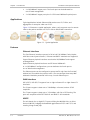
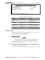
Applications
Typical applications include Ethernet VPN services over E1/T1 links, and
aggregation of enterprise LANs over E1/T1.
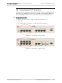
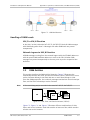
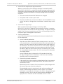
Figure 1-1 illustrates a typical application, where a unit connects users in remote
LANs to the packet network over E1/T1 with an SDH/SONET connection.
Figure 1-1. Typical Application
Features
Ethernet Interfaces
The Fast Ethernet interfaces operate in full or half (10/100BaseT only) duplex,
with flow control (pause frames). Ethernet and 802.3 standards are supported.
Copper Ethernet physical interfaces are electrical 10/100BaseT and support
autonegotiation.
Optical Ethernet physical interfaces are SFP-based 100BaseFx.
In 4 x 10/100BaseT configurations, you can dedicate the fourth port to
out-of-band local management.
The Ethernet ports can be configured to accept traffic only from the first MAC
address(es) from which they receive traffic. You can configure how many MAC
addresses should be protected in this way, for each Ethernet port.
WAN Interfaces
RICi-4E1/T1, RICi-8E1/T1 supports four or eight unframed E1 or eight framed T1
interfaces.
The E1 ports support a data rate of 2.048 Mbps, unframed, and are G.703
compliant.
The T1 ports support a data rate of 1.544 Mbps, with D4 or ESF framing. The
ports are compliant with AT&T TR62411 and ANSI T1.403 standards.
MLPPP
The unit bonds four or eight E1/T1 ports utilizing the Multilink Point-to-Point
Protocol (MLPPP), bridging the bandwidth gap between E1/T1 and E3/T3, and
creating a large virtual pipe.
1-2
Overview
RICi-4E1/T1, RICi-8E1/T1 Ver. 2.0
Installation and Operation Manual
Chapter 1 Introduction
Bridge
RICi-4E1/T1, RICi-8E1/T1 provides a bridging mechanism between the following
bridge ports:
•
Fast Ethernet ports
•
MLPPP bundle over E1/T1 ports (Ethernet over E1/T1)
•
Internal host.
The internal bridge operates in VLAN-unaware or VLAN-aware modes.
The VLAN-aware bridge mode allows the user to create a subgroup of bridge
ports within the bridge. Each such subgroup is associated with a unique VID.
Frames can be forwarded only between bridge ports that are members of the
same VLAN, thus enabling a total separation between different VLAN users within
the same bridge.
In the VLAN-unaware Bridge mode the bridge ignores VLAN tags and forwards
frames only according to the MAC addresses of their sources and destinations.
Ethernet Type (TPID) is configurable per bridge port, therefore the RICi-4E1/T1,
RICi-8E1/T1 unit can be used in networks utilizing Ethertypes other than the
802.1q Ethertype 0x8100.
RICi-4E1/T1, RICi-8E1/T1 supports QoS mapping from Ethernet ports, Ethernet
VLAN priority (802.1p), or DSCP to egress queue priority at E1/T1 level.
Ethernet OAM
RICi-4E1/T1, RICi-8E1/T1 provides Ethernet end-to-end OAM based on 802.1ag
and Y.1731 to enable Ethernet service providers to monitor their services
proactively, measure end-to-end performance, and guarantee that the customers
receive the contracted SLA. Fault monitoring and performance measurement
include Frame Delay, Frame Delay Variation, Frame Loss, and Frame Availability.
Management
Setup, control, and monitoring of status and diagnostics can be performed using
the following methods:
•
•
Inband or out-of-band management:
Inband. Local and remote management via an Ethernet or E1/T1 port.
Out-of-band. Management via a local ASCII terminal connected to the
V.24 (RS-232) DCE control port. In devices with four electrical
10/100BaseT ports, the fourth Ethernet port can be configured as an
out-of-band management port.
The device can be managed via Telnet, Web browser, or SNMP
(RADview-Lite).
Web terminal. This tool is a user-friendly Web-based element management
system for remote device configuration and maintenance. It is embedded in
the units and is provided at no extra cost. The Web terminal application can
be run from any standard Web browser.
RICi-4E1/T1, RICi-8E1/T1 Ver. 2.0
Overview
1-3
Chapter 1 Introduction
•
Installation and Operation Manual
RADview-Lite. RAD’s SNMP-based element management software, providing
SNMP traps, status polling, and configuration download. Remote element
management is available in RADview-Lite via Web-based application.
The following functionalities are available with the internal management
software:
•
Viewing system information
•
Modifying configuration and mode of operation, including setting system
default values and resetting the unit
•
Monitoring performance
•
Initiating connectivity tests
•
•
Ping and Trace Route
Remote software and configuration download/upload (TFTP)
•
Upgrading software.
Security
The management applications are password protected.
RICi-4E1/T1, RICi-8E1/T1 supports the following access authorization levels:
Note
•
Super-user mode for configuration and monitoring
•
User mode for monitoring and configuration view only.
You must re-enter the user name and the password if five minutes have elapsed
without entering at least one character.
The units support the following security protocols, providing a high level of client
server communication security.
•
RADIUS authentication
•
SSL for Web based management application
•
SSH for Secure Shell communication session
Remote Monitoring with Syslog
RICi-4E1/T1, RICi-8E1/T1 uses the Syslog protocol to generate and transport
event notification messages over IP networks to up to five central Syslog servers.
The Syslog operation is compliant with RFC 3164.
Timing
RICi-4E1/T1, RICi-8E1/T1 has a single clock domain with master and fallback
sources for timing. The clock source can be the internal oscillator or loopback
timing (LBT) from an E1/T1 link.
1-4
Overview
RICi-4E1/T1, RICi-8E1/T1 Ver. 2.0
Installation and Operation Manual
Chapter 1 Introduction
Diagnostics
RICi-4E1/T1, RICi-8E1/T1 offers several types of diagnostic and troubleshooting
procedures:
•
Remote loopbacks on the E1/T1 ports, towards line
•
Ping tests
•
Trace Route
•
Bit Error Rate Test (BERT) on the E1/T1 ports
•
Events/Traps – Traps can be masked, per manager IP address, upon user
configuration.
Statistics
RICi-4E1/T1, RICi-8E1/T1 provides statistics and counter capabilities at the
physical Ethernet and MLPPP level (logical layer), and frame statistics at the E1/T1
level.
Event Log File
The event log file includes entries at the system, Ethernet, and E1/T1 levels. The
events are stored and time-stamped in an event log file. Up to 1000 cyclic entries
are maintained.
The NTP client is integrated in RICi-4E1/T1, RICi-8E1/T1. If an NTP server is
available, log file events are marked with the time and the date received from it.
If no NTP server is available, log files are marked with the elapsed time since the
system was started.
Temperature-Hardened Version
A temperature-hardened version is available, significantly extending the permitted
operating temperature range.
Compact Size
RICi-4E1/T1, RICi-8E1/T1 is compact, 1U high and half the width of a standard 19”
rack. It can be mounted in a rack or used as a standalone unit.
RICi-4E1/T1, RICi-8E1/T1 Ver. 2.0
Overview
1-5
Chapter 1 Introduction
1.2
Installation and Operation Manual
Physical Description
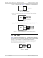
RICi-4E1/T1, RICi-8E1/T1 is a 1U standalone or rack mountable unit.
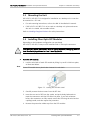
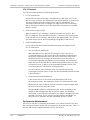
Figure 1-2 illustrates a three-dimensional view of RICi-4E1 and RICi-8E1 with
Ethernet and E1 interfaces. The remaining versions within this range are similar
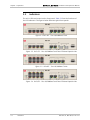
with respect to corresponding numbers of E1 or T1 interfaces. Front panels are
illustrated in Chapter 3.
Figure 1-2. 3-D View
LEDs, interface, and control connectors are located on the front panel. For
additional information, refer to Chapter 2. The power connector is located on the
rear panel.
1-6
Physical Description
RICi-4E1/T1, RICi-8E1/T1 Ver. 2.0
Installation and Operation Manual
1.3
Chapter 1 Introduction
Functional Description
This section lists and explains the key features of RICi-4E1/T1, RICi-8E1/T1.
Bridge
RICi-4E1/T1, RICi-8E1/T1 has multi-port bridging capability with up to six bridge
ports. The bridge supports two modes of operation, VLAN-aware and VLANunaware.
The mechanism of each mode can be described as five different processes:
•
Ingress. Checks each frame entering the bridge to decide if and how this
frame should be passed on to the forwarding process.
•
Learning. Applies to MAC only or MAC VID pairs and learns new MAC table
entries.
•
Aging. Checks the forwarding MAC table periodically.
•
Forwarding. Decides to which bridge port/ports to forward the frame.
•
Transmission. Applies to the VLAN-aware mode only and selects the format
of the transmitted frame at the output port: with VLAN ID (tagged) or
without VLAN ID (untagged).
Bridge features and these five processes are described below for each mode.
RICi-4E1/T1, RICi-8E1/T1 Ver. 2.0
Functional Description
1-7
Chapter 1 Introduction
Installation and Operation Manual
VLAN-Aware Mode
This mode enables creation of sub-groups of bridge ports within the bridge. Each
sub-group is defined per VLAN and is associated with a unique VLAN ID (VID).
Frames containing a VID can be forwarded only between bridge ports that are
members of this specific VLAN, thus enabling a total separation between
different VLAN users within the same bridge.
In addition, each bridge port is associated with Ethernet Type (TPID). The default
is 0x8100 (801.1Q Ether Type), but any number may be configured, thus
enhancing the bridge capability to cope with provider networks that utilize other
Ether Types (e.g. 0x9100).
Bridge Features
1-8
•
Full VLAN-aware bridge, complying with 802.1Q
•
Learning and forwarding according to MAC address and VID
•
Learning of up to 2,048 MAC table entries (MAC + VID pairs)
•
Configuration of the aging time
•
MAC table viewing (learned MACs).
Functional Description
RICi-4E1/T1, RICi-8E1/T1 Ver. 2.0
Installation and Operation Manual
Chapter 1 Introduction
Ingress Process
The ingress process is composed of three steps: frame admission, ingress
filtering and PVID assignment to untagged/priority-only tagged frames.
•
•
Frame admission. Two modes of operation, configured per bridge:
Admit all frames. All frames arriving from the port are admitted and
proceed to the ingress filtering process. PVID is assigned to untagged or
priority only tagged frames.
Admit only VLAN tagged frames. Only VLAN tagged frames are admitted
and allowed to proceed to the ingress filtering process. Untagged or
priority-only tagged frames are discarded.
Ingress filtering. One of the following modes, configured per bridge port:
Enable. Perform ingress filtering according to VID. This means that only
frames that share a VID assigned to this bridge port are admitted.
Disable. All frames are forwarded.
Only admitted frames that pass filtering are submitted to learning and
forwarding processes.
•
PVID assignment. Per bridge port configuration.
In VLAN-aware mode, each received frame entering the bridge is
associated with a single VID. If the received frame does not contain a
VLAN ID (untagged or priority only tagged frames), a specific PVID is
assigned to these frames before they pass to the forwarding process.
This means that the untagged/priority tagged frames that have passed
the admission/ingress filtering are tagged with PVID and proceed to the
forwarding process. Tagged frames will be double-tagged with the PVID
only if Tag Stacking is enabled.
For untagged frames that were tagged during this process to VID=PVID,
the priority tag is assigned at the VLAN priority field, according to the
default priority configuration.
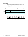
Table 1-1 summarizes the behavior of the ingress process.
RICi-4E1/T1, RICi-8E1/T1 Ver. 2.0
Functional Description
1-9
Chapter 1 Introduction
Installation and Operation Manual
Table 1-1. Ingress process
Frame Admission
Mode
Ingress
Filtering
Mode
Bridge Behavior
Admit all frames
Enable
VLAN tagged frames with a VID (or PVID for
untagged/priority tagged frames) that do not
include the bridge port in their VLAN member
set – are dropped.
Disable
All frames pass.
Enable
VLAN tagged frames with a VID that do not
include the bridge port in their member set –
are dropped. Untagged/priority-only tagged
frames are dropped.
Disable
All VLAN tagged frames pass.
Untagged/priority-only tagged frames are
dropped.
Admit VLAN tagged
frames
Frames that pass this stage are submitted to the forwarding process and to the
learning process.
Learning Process
The learning process observes the source MAC address (SA) and the VID of the
received frame, and updates the forwarding database with the MAC VID pair and
with the bridge port that the frame was received from. The Forwarding Data Base
(FDB) is also referred to as a MAC table.
Entries in the MAC table can be dynamic (inserted by the learning process) or
static (inserted by configuration). A dynamic entry has an aging time associated
with it.
The VLAN-aware bridge is an Independent VLAN Learning (IVL) bridge.
The learning process inserts a new dynamic entry to the MAC table. This entry
consists of a MAC-VID pair and bridge port.
•
If the MAC-VID pair already exists for the same port, the aging time is
updated.
•
If the MAC-VID pair already exists but for a different bridge port (dynamic
entry) the new entry overrides the existing one.
•
If the MAC-VID pair already exists for a different bridge port (static entry) the
static entry prevails.
Aging Process
The aging process checks the forwarding MAC table periodically. Each dynamic
entry-aging period that has exceeded the configured aging time limit is deleted.
The aging period is the time since the last frame for this entry has entered the
bridge. The periodic check of the MAC table (aging time intervals) results in actual
aging time that can reach up to twice the value that was configured by the user.
1-10
Functional Description
RICi-4E1/T1, RICi-8E1/T1 Ver. 2.0
Installation and Operation Manual
Chapter 1 Introduction
Forwarding Process
The forwarding process is performed based on the frame destination MAC VID
pair. The frame is forwarded to the bridge port specified in the MAC table for this
MAC VID pair entry.
Untagged frames are forwarded according to the PVID attached to that frame
during the ingress process.
Frames are forwarded, dropped or flooded as follows:
•
Forwarded:
•
•
If the bridge port of the pair entry (DA, VID) in the MAC table is both an
active bridge port and a member of the VLAN – the frame is forwarded to
that bridge port only.
Dropped:
If the bridge port for the pair entry (DA, VID) in the MAC table is the port
on which the frame was received, the frame is dropped.
If there are no active ports associated with the frame’s VID, or if the VID
is not defined at all, the frame is dropped.
Flooded:
If the pair (DA, VID) has not been learnt and does not exist in the MAC
table, the frame is transmitted to all bridge ports associated with the
frame’s VLAN ID.
Multicasts and broadcasts are flooded only via the bridge ports whose
VLAN IDs are identical to the frame’s VLAN ID.
Transmission Process
After the forwarding process identifies the destination bridge port/ports to which
the frame should be transmitted, the transmission process transmits it with the
appropriate format. For each VLAN and each port, the user can configure the
frame format to be used:
•
•
VLAN-tagged. Frames are transmitted as follows:
VLAN-tagged frames are transmitted unchanged.
Untagged frames are transmitted tagged with priority according to the
default priority of the ingress bridge port, and VID=PVID of the port from
which they have entered.
Priority-tagged frames are transmitted tagged with original priority and
VID = PVID.
Untagged. All frames are transmitted untagged.
RICi-4E1/T1, RICi-8E1/T1 Ver. 2.0
Functional Description
1-11
Chapter 1 Introduction
Installation and Operation Manual
VLAN-Unaware Mode
In this mode the bridge forwarding ignores the VLAN ID of VLAN tagged frames.
Each Ethernet packet received from each bridge port (Ethernet or E1s) is
forwarded according to its destination MAC address.
Bridge Features
•
Learning and forwarding according to MAC address only
•
Learning of up to 2048 MAC addresses
•
Configuration of the aging time
•
VLAN tagged frames transparency (forwarding according to MAC only)
•
MAC table viewing (learned MACs).
Ingress Process
All frames are accepted in this mode: untagged, priority-tagged or VLAN-tagged.
Learning and forwarding is based on the MAC addresses, with no regard to the
VLAN. This mode is sometimes regarded to as transparent mode, due to “tag
transparency”.
Learning Process
The learning process observes the source MAC address (SA) of the received frame
and updates the forwarding database (FDB) with the MAC and the bridge port
that the frame was received from. FDB is also referred to as MAC table.
The learning process inserts a new entry into the MAC table. This entry consists
of the MAC and the bridge port.
•
If the MAC already exists for the same bridge port, the aging time will be
updated.
•
If the MAC already exists, but for a different bridge port, (dynamic entry) the
new entry will override the existing one.
Aging Process
The aging process checks the forwarding MAC table periodically. Each dynamic
entry aging time period that has exceeded the configured Aging Time Limit is
deleted. The aging time period is the period of time since the last frame for this
entry has entered the bridge. The periodic check of the MAC table (aging time
intervals), results in an actual aging time that can reach up to twice the value that
was configured by the user.
1-12
Functional Description
RICi-4E1/T1, RICi-8E1/T1 Ver. 2.0
Installation and Operation Manual
Chapter 1 Introduction
Forwarding Process
The forwarding process is performed based on the frame MAC Destination
Address (MDA). The frame is forwarded to the Bridge/port specified in the MAC
table for this MAC.
Frames are forwarded, dropped or flooded at this stage for the following reason:
•
Forwarded: A frame will be forwarded according to its DA, to the bridge port
where its DA was learned.
•
Dropped: If the port for that DA entry in the MAC table is the port on which
the frame was received, the frame will be dropped.
•
Flooded:
If there is no information regarding the DA in the MAC table, the frame is
flooded to all ports.
Frames with multicast or broadcast address are flooded to all ports.
Transmission Process
In this bridge mode (VLAN-unaware), the frames are transmitted unchanged: No
tags are added or removed.
VLAN Stacking
VLAN stacking mode for a bridge port refers to the addition of a tag to an
incoming frame either at ingress or egress (regardless of whether it already has
an existing VLAN tag), and removal of a tag at ingress or egress when the frame
leaves from this port.
This setting is independent of the bridge activity.
RICi-4E1/T1, RICi-8E1/T1 Ver. 2.0
Functional Description
1-13
Chapter 1 Introduction
Installation and Operation Manual
Quality of Service
RICi-4E1/T1, RICi-8E1/T1 support QoS mapping to priority queues (3 PQ, strict
priority, per bridge port) at the E1/T1 egress according to one of the following:
•
VLAN priority (802.1p)
•
DSCP (ToS byte)
•
Port-based
0
0
1
1
2
3
4
5
6
7
8
9
0
2
1
2
3
4
5
6
7
8
9
0
3
1
2
3
4
5
6
7
8
9
0
1
IP
HEADER
VERSION
IHL
TOTAL LENGTH
TOS
IDENTIFICATION
FLAGS
FRAGMENT OFFSET
TIME TO LIVE
PROTOCOL
HEADER CHECKSUM
SOURCE ADDRESS
DESTINATION ADDRESS
OPTIONS
PADDING
Figure 1-3. IP Header
Bit 0
Bit 1
DS5
DS4
Bit 2
DS3
Bit 3
DS2
Bit 4
DS1
Bit 5
DS0
Bit 6
XX
Bit 7
XX
DSCP: six bits (DS5–DS0)
Figure 1-4. ToS Byte DSCP Field
1-14
Functional Description
RICi-4E1/T1, RICi-8E1/T1 Ver. 2.0
Installation and Operation Manual
Chapter 1 Introduction
Management
The performance of RICi-4E1/T1, RICi-8E1/T1 can be locally monitored from an
ASCII terminal, or from a remote site using Telnet, SNMP, Web terminal or
RADview-Lite.
Inband Management
RICi-4E1/T1, RICi-8E1/T1 enable configuring, monitoring and following up on
statistics via Telnet, SNMP and the Web.
Out-of-Band Management
RICi-4E1/T1, RICi-8E1/T1 allows full configuration and diagnostics via an ASCII
terminal. The ASCII terminal is connected to the control port on the front panel.
Chapter 3 explains how to activate the ASCII terminal and provides general
instructions on navigating to various system menus and windows and modifying
data.
Units with 4 x 10/100BaseT configurations enable managing the respective unit
via a dedicated Fast Ethernet port using a Telnet server, SNMP V1, or Web based
tools such as Web terminal and RADview-Lite. Refer to Chapter 3 for additional
information.
Management Access
The architecture allows access from every bridge port to both the host and the
remote site devices. Depending on the configuration mode, you may dedicate a
port to management traffic, thus separating management and user traffic.
In this scenario, traffic coming from the remote CPE uses two VLANs, one for user
traffic, for which the CPE may use tag stacking, and the other one for
management traffic. All CPEs connected to RICi-4E1/T1, RICi-8E1/T1 share the
same management VLAN.
In VLAN-aware mode, RICi-4E1/T1, RICi-8E1/T1 forwards the management traffic
to the Ethernet cloud network management station. Using a different VLAN
maintains strict separation of user and management traffic.
RICi-4E1/T1, RICi-8E1/T1 Ver. 2.0
Functional Description
1-15
Chapter 1 Introduction
Installation and Operation Manual
1.4
Technical Specifications
This section lists the technical specifications of RICi-4E1/T1, RICi-8E1/T1.
General
Internal Bridge
Ports
• Fast Ethernet (up to four)
• Local host (one)
• MLPPP (one port combining up to eight E1/T1 lines)
Control Port
Monitoring
LAN Table
Up to 2,048 MAC addresses of which 30 are static
Operation Mode
VLAN-aware, VLAN-unaware
Filtering and
forwarding
Transparent or Filter
Interface
RS-232/V.24 (DTE asynchronous)
Data Rate
9.6, 19.2, 115.2 kbps
Connector
DB-9, female
Statistics
System and physical layer Alarms
ETH or E1 frame counters
Ethernet physical layer statistics and frame counters
Indicators
PWR (green)
On: The unit is running
Off: The unit is off
TST (green)
On: Self test succeeded
Off: Self test or diagnostics underway
ALM (red)
On: Interface alarm
Off: No alarm
LINK (green) for
each Ethernet port
On: Ethernet link is active
ACT (yellow) for
each Ethernet port
Blinking: Ethernet frame received or sent within the last
second
Off: Ethernet link is inactive
Off: No frame received or sent within the last second
1-16
Technical Specifications
RICi-4E1/T1, RICi-8E1/T1 Ver. 2.0
Installation and Operation Manual
Power
Physical
Environment
Chapter 1 Introduction
LOC (red) for each
port (E1 only)
On: Local sync loss
REM (red) for each
port (E1 only)
On: Remote sync loss
RED (red) for each
port (T1 only)
On: Local sync loss
YEL (yellow) for
each port (T1
only)
On: Remote sync loss
AC Source
100–240 VAC, 50/60 Hz
DC Source
48/60 VDC nominal (40–72 VDC)
Power
Consumption
9W
Height
43.7 mm (1.7 in) (1U)
Width
215.0 mm (8.5 in)
Depth
300.0 mm (11.8 in)
Weight
2.2 kg (4.7 lb)
Temperature
Regular option:
0 to 50°C (32 to 122°F)
Off: No loss
Off: No loss
Off: No loss
Off: No loss
Temperature-hardened option:
-22 to 70°C (7.6 to 158°F)
Humidity
Up to 90%, non-condensing
Interfaces
This section provides the technical specifications of the
RICi-4E1/T1, RICi-8E1/T1 interfaces.
E1/T1 Interfaces
The user-traffic interfaces of RICi-4E1/T1, RICi-8E1/T1 are four or eight E1, or
four or eight T1 connections.
RICi-4E1/T1, RICi-8E1/T1 Ver. 2.0
Technical Specifications
1-17
Chapter 1 Introduction
Installation and Operation Manual
Table 1-2. E1 Interface Specification
Specifications
E1 Ports
Interface
E1 Balanced or unbalanced 75
(with adapter cable)
Standards
G.703
Framing
Unframed
Data Rate
2.048 Mbps
Line Coding
HDB3
Interface type, connector
Electrical, RJ-45
Table 1-3. T1 Interface Specification
Specifications
T1 Ports
Interface
T1 Balanced 100
Standards
AT&T TR62411, ANSI T1.403
Framing
D4, ESF
Data Rate
1.544 Mbps
Line Coding
B8Zs
Interface type, connector
Electrical, RJ-45
Fast Ethernet Interfaces
The network communication in RICi-4E1/T1, RICi-8E1/T1 is channeled through up
to four 10/100BaseT Ethernet ports. There is also an option to have two
10/100Base T ports and two fiber optic SFP ports. The interface specifications
are listed in Table 1-4 and Table 1-5.
Table 1-4. Fast Ethernet (10/100BaseT) Interface Specification
1-18
Specifications
Ethernet Ports
Interface
10/100BaseT Fast Ethernet Interface
Standards
Ethernet, Relevant sections of IEEE 802.3,
802.3u, 802.1p and 802.1Q
Maximum Frame Size
1,900 Bytes
Data Rate
100 Mbps
Interface type, connector
Electrical, RJ-45
Range
100 meters/328 feet on UTP category 5 cables
Autonegotiation
Supported
Flow control
Pause frames
Duplex modes
Full/half duplex
Technical Specifications
RICi-4E1/T1, RICi-8E1/T1 Ver. 2.0
Installation and Operation Manual
Chapter 1 Introduction
Table 1-5. Fast Ethernet (100BaseFx) Interface Specification
Specifications
Ethernet Ports
Interface
100BaseFx Fast Ethernet Interface
Standards
Ethernet, Relevant sections of IEEE 802.3,
802.3u, 802.1p and 802.1Q
Maximum Frame Size
1,900 Bytes
Data Rate
100 Mbps
Interface type, connector
Optical, LC
Flow control
Pause frames
SFP Supported Types
SFP-1: 1310 nm, 2 km (1.2 miles)
SFP-2: 1310 nm, 15 km (9.3 miles)
SFP-3: 1310 nm, 40 km (24.8 miles)
SFP-4: 1550 nm, 80 km (49.7 miles)
SFP-10a: Tx – 1310 nm, Rx – 1550 nm, single
fiber, 20 km (12.4 miles)
RICi-4E1/T1, RICi-8E1/T1 Ver. 2.0
Technical Specifications
1-19
Chapter 1 Introduction
1-20
Technical Specifications
Installation and Operation Manual
RICi-4E1/T1, RICi-8E1/T1 Ver. 2.0
Chapter 2
Installation and Setup
This chapter includes the following topics:
•
Site requirements and specifications
•
Package contents
•
Required equipment
•
Installation and setup.
2.1
Introduction
RICi-4E1/T1, RICi-8E1/T1 is shipped ready to use, with factory defaults set. The
device is designed as a desktop units or for mounting in a 19-inch rack. For rack
installation instructions, refer to the Rack Mounting Kit for 19-inch Racks guide
that comes with the RM kit.
After installing the unit, use an ASCII terminal connected to the CONTROL port to
perform any configuration necessary. The configuration procedures are described
in Chapter 3 and Chapter 4.
In case of problems, refer to Chapter 6.
Warning
No internal settings, adjustment, maintenance and repairs should be performed
by either the operator or the user. Such activities must be performed only by
skilled personnel who are aware of the hazards involved.
Always observe standard safety precautions during installation, operation and
maintenance of this product.
2.2
Site Requirements and Prerequisites
AC-powered units should be installed within 1.5 meters (5 feet) of an easily
accessible grounded AC outlet, capable of supplying the required voltage in the
range of 100 to 240 VAC at 50/60 Hz. DC-powered units require 48/60 VDC
(40–72 VDC))
Allow at least 90 cm (36 in) of free space in front of the unit to ensure easy
operator access. For continuous product operation, allow at least 10 cm of free
space at the front and at least 15 cm at the rear of the unit for cable
connections and ventilation. For proper ventilation, keep at least 2.5 cm free
space from the sides and the top of the unit.
The ambient operating temperature is 0 to 50° C (32 to 122°F), at a relative
humidity of up to 90%, non-condensing.
RICi-4E1/T1, RICi-8E1/T1 Ver. 2.0
Site Requirements and Prerequisites
2-1
Chapter 2 Installation and Setup
2.3
Installation and Operation Manual
Package Contents
The package contains the following items:
•
One RICi-4E1, RICi-4T1, RICi-8E1, or RICi-8T1 unit
•
AC power cord or DC adaptor connector
•
RM-35 kit for mounting in a 19” rack (if ordered)
•
WM-35 kit for mounting a unit on a wall (if ordered).
2.4
Required Equipment
RICi-4E1/T1, RICi-8E1/T1 does not require special tools for installation. You only
need a screwdriver for mounting the unit in a 19-inch rack.
RICi-4E1/T1, RICi-8E1/T1 is equipped with the appropriate power cable for the
respective country or region. You connect the power socket on the rear panel to
the mains.
Refer to the following table to determine which cables and connectors are
required for installation. Appendix A specifies all connector pinouts.
Table 2-1. Required Connection Media
Interface
Cable/Connector
Control port
Straight RS-232/V.24 cable with DB-9 female
connector for ASCII terminal
Fast Ethernet interface
RJ-45, 8-pin connection media
E1/T1 interface
RJ-45, 8-pin connection media
For an unbalanced E1 interface, use the adapter cable
provided
2-2
Required Equipment
RICi-4E1/T1, RICi-8E1/T1 Ver. 2.0
RICi-4E1/T1, RICi-8E1/T1 Installation and Operation Manual
2.5
Chapter 2 Installation and Setup
Mounting the Unit
RICi-4E1/T1, RICi-8E1/T1 is designed for installation as a desktop unit. It can also
be mounted in a 19" rack.
•
For rack mounting instructions, refer to the RM-34 installation kit manual.
•
If RICi-4E1/T1, RICi-8E1/T1 is to be used as a desktop unit, place and secure
the unit on a stable, non-movable surface.
Refer to Handling Energized Products for safety instructions.
2.6
Installing Fiber Optic SFP Modules
Depending on the hardware configuration you purchased,
RICi-4E1/T1, RICi-8E1/T1 may use SFP modules with LC fiber optic connectors.
Third-party SFP optical transceivers must be agency-approved, complying with the
local laser safety regulations for Class 1 laser equipment.
Warning
³
To install SFP modules:
1. Lock the wire latch of each SFP module by lifting it up until it clicks into place,
as illustrated below.
Note
Some SFP models have a plastic door instead of a wire latch.
Figure 2-1. Locking the SFP Wire Latch
2. Carefully remove the dust covers from the SFP slot.
3. Insert the rear end of SFP into the socket, and push slowly backwards to
mate the connectors until the SFP clicks into place. If you feel resistance
before the connectors are fully mated, retract the SFP using the wire latch as
a pulling handle, and then repeat the procedure.
4. Remove the protective rubber caps from the SFP modules.
RICi-4E1/T1, RICi-8E1/T1 Ver. 2.0
Installing Fiber Optic SFP Modules
2-3
Chapter 2 Installation and Setup
³
Installation and Operation Manual
To remove the SFP module:
1. Disconnect the fiber optic cables from the SFP module.
2. Unlock the wire latch by lowering it downwards (as opposed to locking).
3. Hold the wire latch and pull the SFP module out of the Ethernet port.
2.7
Connecting to Ethernet Equipment
RICi-4E1/T1, RICi-8E1/T1 is connected to the Fast Ethernet equipment via the
fiber optic LC or 8-pin RJ-45 ports. Refer to Appendix A for the RJ-45 connector
pinout..
³
To connect to Fast Ethernet equipment with fiber optic interface:
•
Connect RICi-4E1/T1, RICi-8E1/T1 to the Ethernet equipment using a standard
fiber optic cable terminated with an LC connector.
Figure 2-2. Front Panel - Two 10/100BaseT and two SFP-Based Optical Links
³
To connect to Fast Ethernet equipment with 10/100BaseT interface:
•
Connect the LAN to an RJ-45 connector designated 10/100BaseT.
Figure 2-3. Front Panel – Four 10/100BaseT Links
2-4
Connecting to Ethernet Equipment
RICi-4E1/T1, RICi-8E1/T1 Ver. 2.0
RICi-4E1/T1, RICi-8E1/T1 Installation and Operation Manual
2.8
Chapter 2 Installation and Setup
Connecting to E1/T1 Equipment
E1/T1 devices are connected to RICi-4E1/T1, RICi-8E1/T1 via 4 or eight balanced
RJ-45 ports. An unbalanced E1 interface is provided via the CBL-RJ45/2BNC/E1/X
RJ-45 to BNC adapter cable. Refer to Appendix A for the connector pinouts.
³
To connect to E1 or T1:
•
Connect an E1 or T1 line to an RJ-45 connector labeled E1 or T1
(1–4 or 8).
•
For unbalanced E1 connections, use the RAD-supplied adaptor.
Figure 2-4. Front Panel – Four E1 Ports
Figure 2-5. Front Panel – Eight T1 Ports
RICi-4E1/T1, RICi-8E1/T1 Ver. 2.0
Connecting to E1/T1 Equipment
2-5
Chapter 2 Installation and Setup
2.9
Installation and Operation Manual
Connecting to Management Stations
Connecting to an ASCII Terminal
RICi-4E1/T1, RICi-8E1/T1 is connected to an ASCII terminal via a 9-pin D-type
female connector labeled CONTROL. Refer to Appendix A for the connector
pinout.
³
To connect the ASCII terminal:
1. Connect the male 9-pin D-type connector of the CBL-DB9F-DB9M-STR Control
Port cable to the CONTROL connector.
2. Connect the other end of this cable to an ASCII terminal.
Figure 2-6. Front Panel – Control Port
Caution
2-6
Terminal cables must have a frame ground connection. Use ungrounded cables
when connecting a supervisory terminal to a DC-powered unit with floating
ground. Using improper terminal cable may result in damage to supervisory
terminal port.
Connecting to Management Stations
RICi-4E1/T1, RICi-8E1/T1 Ver. 2.0
RICi-4E1/T1, RICi-8E1/T1 Installation and Operation Manual
Chapter 2 Installation and Setup
2.10 Connecting to Power
RICi-4E1/T1, RICi-8E1/T1 is available with AC power or DC power. The power
connector is located on the rear panel. Before you connect
RICi-4E1/T1, RICi-8E1/T1 to the power, refer to Handling Energized Product at the
front of this manual.
Before connecting or disconnecting any communication cable, the unit must be
grounded by connecting its power cord to a power outlet with a ground terminal,
and by connecting the ground terminal on the panel (if provided) to a protective
ground.
Warning
Any interruption of the protective (grounding) conductor (inside or outside the
instrument) or disconnecting of the protective ground terminal can make this
unit dangerous. Intentional interruption is prohibited.
Connecting AC Power
AC power is supplied via a standard 3-prong inlet with an integral fuse holder.
AC power should be supplied through the 1.5m (5 ft) standard power cord
terminated by a 3-prong socket. This cord ships with the unit.
³
To connect AC power:
1. Connect the power cord to the power connector on the rear panel of the
RICi-4E1/T1, RICi-8E1/T1 unit.
2. Connect the power cord to mains outlet.
The unit turns on automatically upon connection to the mains.
Connecting DC Power
The unit ships with a special IEC 60320 adapter to facilitate a -48/-60 VDC power
connection.
³
To connect DC power:
•
Refer to the DC power supply connection supplement located on the
Technical Documentation CD, or at the back of the hardcopy manual, for
instructions how to wire the DC adapter. Refer to the Handling Energized
Products section at the front of this manual for safety instructions.
RICi-4E1/T1, RICi-8E1/T1 Ver. 2.0
Connecting to Power
2-7
Chapter 2 Installation and Setup
2-8
Connecting to Power
Installation and Operation Manual
RICi-4E1/T1, RICi-8E1/T1 Ver. 2.0
Chapter 3
Operation
This section explains how to get started and operate the unit as follows:
•
Explains how to turn the unit on and off
•
Provides a detailed description of the front panel controls and indicators and
their functions
•
Provides instructions for using a terminal connected to the control port of the
RICi-4E1/T1, RICi-8E1/T1 unit
•
Describes how to navigate menus
•
Defines the configuration alternatives.
For a detailed explanation of the parameters in the menus, refer to Chapter 4.
3.1
³
Turning On the Unit
To turn on RICi-4E1/T1, RICi-8E1/T1:
•
Connect the power cord to the mains.
The PWR indicator turns on and remains on as long as
RICi-4E1/T1, RICi-8E1/T1 receives power.
Once installed, RICi-4E1/T1, RICi-8E1/T1 does not require attention except for
occasionally monitoring the front panel indicators.
You only have to configure the unit in compliance with local requirements or
when performing tests.
RICi-4E1/T1, RICi-8E1/T1 Ver. 2.0
Turning On the Unit
3-1
Chapter 3 Operation
RICi-4E1/T1, RICi-8E1/T1 Installation and Operation Manual
3.2
Indicators
The unit's LEDs are located on the front panel. Table 3-1 lists the functions of
the LED indicators. The figures below illustrate typical front panels.
Figure 3-1. RICI-4E1 - Four 10/100BaseT Links
Figure 3-2. RICI-4T1 - Two 10/100BaseT and Two SFP-Based Optical Links
Figure 3-3. RICI-8E1 - Four 10/100BaseT Links
Figure 3-4. RICI-8T1 - Two 10/100BaseT and Two SFP-Based Optical Links
3-2
Indicators
RICi-4E1/T1, RICi-8E1/T1 Ver. 2.0
RICi-4E1/T1, RICi-8E1/T1 Installation and Operation Manual
Chapter 3 Operation
Table 3-1. RICi-4E1/T1, RICi-8E1/T1 LEDs and Controls
Name
PWR
Color
Green
Function
On: Unit is running
Off: Unit is off
TST
Green
On: Self test succeeded
Off: Self test or diagnostics underway
ALM
Red
On: Error on at least one interface
Off: No alarm
LOC for each E1 port
Red
On: Local sync loss
Off: No loss
REM for each E1 port
Red
On: Remote sync loss
Off: No loss
RED for each T1 port
Red
On: Local sync loss
Off: No loss
YEL for each T1 port
Yellow
On: Remote sync loss
Off: No loss
LINK for each
Ethernet port
Green
ACT for each
Ethernet port
Yellow
On: Ethernet link is active
Off: Ethernet link is inactive
Blinking: Ethernet frame received or sent
within the last second
Off: No frame received or sent within the last
second
RICi-4E1/T1, RICi-8E1/T1 Ver. 2.0
Indicators
3-3
Chapter 3 Operation
RICi-4E1/T1, RICi-8E1/T1 Installation and Operation Manual
3.3
Default Settings
Some configuration parameters in RICi-4E1/T1, RICi-8E1/T1 may be set to the
default values. Configuration parameters set to the default values belong to one
of the two following categories:
•
Set/configured defaults. These defaults are visible when entering the screen,
for example the terminal bit rate, which is set to 115200 bps when started.
•
Not set/configured defaults. These defaults are not visible when entering the
screen and are presented by a blank field. They will show after selecting
‘Save’ in the respective screen. For example, the default for Ingress Filtering
appears once you saved changes in the Bridge Configuration screen.
Configuration parameters without default values assigned require values be
assigned, otherwise you will be unable to save the settings.
Table 3-2 lists the default settings of the RICi-4E1/T1, RICi-8E1/T1 configuration
parameters.
Table 3-2. Default System Settings
3-4
Parameter
Default Value
Device Name
RICi-4E1/RICi-4T1/RICi-8E1/ RICi-8T1
Description
Fast Ethernet over Four/Eight E1/T1 NTU
Location
Location of the device
Contact Person
Name of the contact person
Host IP Address
0.0.0.0
Host IP Mask
255.255.255.0
Host Default Gateway
0.0.0.0
Read Community
Public
Write Community
Private
Trap Community
Public
Host Tagging
Untagged
Security Definition
All
Telnet/SSH Access
Enable
SNMP Access
Enable
Web Access
Enable
Baud Rate
115.2 kbps
Default Settings
RICi-4E1/T1, RICi-8E1/T1 Ver. 2.0
RICi-4E1/T1, RICi-8E1/T1 Installation and Operation Manual
Chapter 3 Operation
Table 3-3. Default RADIUS Settings
Parameter
Default Value
Server Sequence Number
1
Server Status
Not connected
Server Access
Disable
Server IP Address
0.0.0.0
Number of Retries
2
Timeout
2
Authentication Port
1812
Table 3-4. Default Syslog Settings
Parameter
Default Value
Device Logging Status
Disable
Device UDP Port
514
Facility
Local 1
Severity Level
Minor
Server Sequence Number
1
Server Access
Disable
Server IP Address
0.0.0.0
Server UDP Port
514
Table 3-5. Default E1 Settings
Parameter
Default Value
Activation
Up
Transmit Clock Source
LBT
Receiver Sensitivity
-43
Line Code
HDB3
Table 3-6. Default T1 Settings
Parameter
Default Value
Activation
Up
Transmit Clock Source
LBT
Frame Type
Framed - ESF
Line Mode
CSU
Line BuildOut
0 dB
RICi-4E1/T1, RICi-8E1/T1 Ver. 2.0
Default Settings
3-5
Chapter 3 Operation
RICi-4E1/T1, RICi-8E1/T1 Installation and Operation Manual
Sync
Fast
Receiver Sensitivity
-36 dB
Line Code
B8ZS
Table 3-7. Default Ethernet Settings
Parameter
Default Value
Port Status
Up
Autonegotiation
Enable
Max Capability Advertised
100Base - TX full duplex mode
Flow Control
Enable
Table 3-8. Default Bridge Settings
Parameter
Default Value
Aging Time
300
Forwarding Mode
Filter
VLAN Mode
Unaware
Bridge Ports
1
2
3
4
5
6
=
=
=
=
=
=
Reserved for management host
MLPPP
Ethernet 1
Ethernet 2
Ethernet 3
Ethernet 4
Table 3-9. Default Bridge Port Settings
Parameter
Default Value
Activation
Enable
Port VID/Stacking VID
2
Copy Original Priority
Disable
Default Priority Tag
0
Egress Tag Handling
None
Ingress Tag Handling
None
TPID (Ether Type)
8100
Table 3-10. Default OAM Settings
3-6
Menu
Parameter
Default Value
End-to-End
Standard OAM MAC Address
0180C2000030
Default Settings
RICi-4E1/T1, RICi-8E1/T1 Ver. 2.0
RICi-4E1/T1, RICi-8E1/T1 Installation and Operation Manual
Chapter 3 Operation
Standard OAM EtherType
8902
MD Names
MD Format
String
Flows
Protocol Type
Standard
MAID
MA Format
String
MEP
OAM Destination Address Type
Multicast
MD Level
3
OAM Mode
Disabled
Continuity Verification Mode
Disabled
CC Interval
1 sec
Performance Monitoring
Disabled
Priority
0
Delay Objective
1
Delay Variation Objective
1
Rising Threshold
1 or 1E-10
Falling Threshold
1 or 1E-10
Event Reporting Type
None
Sampling Interval
1
Service
RICi-4E1/T1, RICi-8E1/T1 Ver. 2.0
Default Settings
3-7
Chapter 3 Operation
RICi-4E1/T1, RICi-8E1/T1 Installation and Operation Manual
3.4
Configuration and Management Alternatives
You can locally configure and monitor RICi-4E1/T1, RICi-8E1/T1 from an ASCII
terminal connected to the relevant unit’s control port, or remotely using
ConfiguRAD or RADview-Lite. If you choose the remote option, the relevant PC
requires an SNMP agent and a Web browser.
Working with an ASCII Terminal
RICi-4E1/T1, RICi-8E1/T1 includes a V.24/RS-232 asynchronous DTE port
designated CONTROL, which is terminated in a 9-pin D-type female connector.
The control port continuously monitors the incoming data stream and
immediately responds to any input string received through this port.
The control port can be configured to communicate at the following rates: 9.6,
19.2, or 115.2 kbps.
³
To start a terminal control session:
1. Make sure that all cables are properly connected to the relevant connectors.
2. Connect that the unit is connected to a PC equipped with an ASCII terminal
emulation application, for example Hyper Terminal or Procomm.
3. Turn on the control terminal PC and set its default port parameters to
115,200 bits per second, 8 bits/character, 1 stop bit and No Parity.
4. Set the terminal emulator to ANSI VT100 to optimize the view of the system
menus.
5. Set the terminal emulator to view a 132-character screen width.
6. Once the system initialized and completed the self-tests, a menu appears
displaying the results of the initialization and the self-tests.
Logging In
³
For read/write permissions:
1. Under User Name, enter su.
2. Under Password, enter 1234 (default password).
³
For read-only permissions:
1. Under User Name, enter user.
2. Under Password, enter 1234 (default password).
Note
• It is recommended to change default passwords to prevent unauthorized
access to the unit.
• If you do not enter at least one character within 5 minutes, you will have to
log in again.
3-8
Configuration and Management Alternatives
RICi-4E1/T1, RICi-8E1/T1 Ver. 2.0
RICi-4E1/T1, RICi-8E1/T1 Installation and Operation Manual
Chapter 3 Operation
Choosing Options
³
To choose an option:
1. Type the number corresponding to the option, and press <Enter>.
2. If you change any parameter in the menu, the Save option appears as the last
option in the menu.
Note
In the OAM menus, the Save option does not appear as the last option in the
menu. You save changes in the OAM menus by typing S and pressing <Enter>.
3. To save changes, type the number associated with Save in the respective
menu or type S if it is an OAM menu, and press <Enter>.
RICi-4E1/T1, RICi-8E1/T1 updates its database with the new value or
displays a new menu for the selected option.
4. If you press <ESC> to exit the menu without saving changes, the following
message appears:
“Do you want to save changes (Y/N/C)?”
Type the appropriate letter to save or not save your changes
(Yes/No/Cancel).
Note
If a parameter offers only two settings, typing the number associated with the
relevant option and pressing <Enter> will toggle between the two available
settings.
Figure 3-5 illustrates a typical screen displaying main items.
Product title line (RICi-4E1)
Short message
1.
2.
3.
4.
5.
Sub Menu>
Sub Menu>
Parameter X [Range] …… (value)
Parameter Y>
(Select value from the list)
Table Z []
prompt>
Main>Configuration>System>
Help line message
Help line of keyboard shortcuts, such as “Esc-prev” for
returning to the previous menu
-----------Division screen line -----------------Scroll messages
Figure 3-5. Sample Screen
Some management screens, such as the Inventory table and the Manager table,
exceed the size of regular menus and require scrolling to navigate between
parameters. In addition, you need to press specific keys to navigate to the
desired parameters.
RICi-4E1/T1, RICi-8E1/T1 Ver. 2.0
Configuration and Management Alternatives
3-9
Chapter 3 Operation
³
³
RICi-4E1/T1, RICi-8E1/T1 Installation and Operation Manual
To navigate inside a table:
•
To scroll left or right, press <Ctrl>+L or <Ctrl>+R respectively.
•
To move to the left or the right, press the Left Arrow or Right Arrow keys.
•
To move up or down, press the Up Arrow or Down Arrow keys.
•
To move to the next editable cell, press <Tab>.
•
To navigate to a specific cell, press G<row number>, <col number>.
To get help on navigating a table:
•
Press <?>; a help screen appears displaying the shortcut keys as illustrated in
Figure 3-6.
Table Hot Keys
'L'
'd'
'a'
'm'
'c'
TAB
-
move left
scroll down
'D' - move down
add row
't' - remove row
represent entry as menu
clear table
select next changeable cell
S <row number>,<col number> - select cell
Figure 3-6. Typical Help Screen
Note
• Screens are best viewed with the terminal screen width set to 132 characters.
• If the respective screen does not have a help screen assigned, an error
returns.
Ending a Terminal Session
³
To end the current terminal session:
•
Press <&>.
After ending a session, it is necessary to enter again a valid user name and
password to start a new session.
Working with Web Terminal
Web-based remote access terminal management software provides a
user-friendly interface for configuring, collecting statistics and performing tests.
3-10
Configuration and Management Alternatives
RICi-4E1/T1, RICi-8E1/T1 Ver. 2.0
RICi-4E1/T1, RICi-8E1/T1 Installation and Operation Manual
Chapter 3 Operation
Web Browser Requirements
³
•
Internet Explorer 6.0 and up, running on Windows™
•
Netscape Communicator 7.0 and up, running on Windows™, HPOV or Linux
•
Firefox 1.0.4 and up, running on Windows™
•
Mozilla 1.4.3 and up, running on Linux.
Before you start using a Web browser for remote management or monitoring:
•
Enable scripts.
•
Configure the firewall that might be installed on your PC to allow access to
the destination IP address.
•
Disable pop-up blocking software, such as Google Popup Blocker. You may
also have to configure spyware and adware protecting software to accept
traffic from/to the destination IP address.
•
To prevent configuration errors, you must flush the browser’s cache
whenever you return to the same screen.
Logging In
³
To log in from a Web browser:
1. Connect the Ethernet port to the LAN.
2. Verify that an IP address has been assigned to the relevant unit, using an
ASCII terminal.
3. Open the Web browser.
4. Disable any pop-up blocking software, such as Google Popup Blocker.
5. In the address field, enter the IP address of RICi-4E1/T1, RICi-8E1/T1 and then
press <Enter>. The address line reads something like http://172.16.100.253.
The Opening window appears.
6. Click LOGIN; you are asked for the user name and the password.
7. Enter your user name and the password. The default user name for
read/write permission is su and the default password is 1234.
The ConfiguRAD Main menu appears.
Notes
• It is recommended to change default passwords to prevent unauthorized
access to the unit.
• RICi-4E1/T1, RICi-8E1/T1 allows six management sessions to be active
simultaneously: five network sessions (Telnet, ConfiguRAD, RADview-Lite) and
one ASCII terminal session.
• If no user input is detected for 5 minutes during a ConfiguRAD session,
RICi-4E1/T1, RICi-8E1/T1 automatically disconnects from the management
station.
RICi-4E1/T1, RICi-8E1/T1 Ver. 2.0
Configuration and Management Alternatives
3-11
Chapter 3 Operation
RICi-4E1/T1, RICi-8E1/T1 Installation and Operation Manual
Navigating the Web Terminal Menus
At the left-hand bottom corner, Web terminal provides auxiliary management tools:
³
•
Status – shows the number of users currently managing the unit.
•
Trace – opens an additional pane for system messages, progress indicators
(ping, software and configuration file downloads) and alarms.
•
Refresh All – refreshes the data currently displayed.
To choose an option:
1. In the Web terminal screen, click the desired link to display the next menu.
2. Once the target screen is displayed, select a value from the drop-down box or
manually enter it into the field.
Working with RADview-Lite
RADview-Lite is a user-friendly and powerful SNMP-based element management
system (EMS), used for planning, provisioning, and managing heterogeneous
networks. RADview-Lite provides capabilities to monitor RAD products and
networks using their respective SNMP agents. You can use configuration and
diagnostic capabilities via ConfiguRAD.
Contact your local distributor for additional information on RADview-Lite.
3-12
Configuration and Management Alternatives
RICi-4E1/T1, RICi-8E1/T1 Ver. 2.0
RICi-4E1/T1, RICi-8E1/T1 Installation and Operation Manual
Chapter 3 Operation
Menu Map
Use the menu tree below as a reference when configuring and monitoring
RICi-4E1/T1, RICi-8E1/T1. Chapter 4 illustrates menus and describes parameters.
Figure 3-7. Menu Map
RICi-4E1/T1, RICi-8E1/T1 Ver. 2.0
Configuration and Management Alternatives
3-13
Chapter 3 Operation
RICi-4E1/T1, RICi-8E1/T1 Installation and Operation Manual
3.5
³
To turn RICi-4E1/T1, RICi-8E1/T1 off:
•
3-14
Turning Off the Unit
Remove the power cord from the power source.
Turning Off the Unit
RICi-4E1/T1, RICi-8E1/T1 Ver. 2.0
Chapter 4
Configuration
This chapter illustrates the configuration screens and explains their parameters.
Examples are given from a terminal screen, but most of the menus are similar for
Telnet and Web terminal.
The menu tree of the management software is illustrated in Chapter 3.
4.1
Configuring for Management
The initial configuration of management parameters is performed via an ASCII
terminal. Once the RICi-4E1/T1, RICi-8E1/T1 host IP parameters are set, it is
possible to access them via Telnet or Web terminal to configure the units
for operation. Perform the following steps in order to configure the devices for
management:
³
Note
To configure RICi-4E1/T1, RICi-8E1/T1 for first use:
•
Configuring Host IP Parameters.
•
Entering Device Information.
•
Configuring Users and Management Access Permissions.
•
Configuring Terminal Parameters.
Make sure that you save your settings at each configuration screen.
RICi-4E1/T1, RICi-8E1/T1 Ver. 2.0
Configuring for Management
4-1
Chapter 4 Configuration
RICi-4E1/T1, RICi-8E1/T1 Installation and Operation Manual
Defining Host IP Parameters
You can manage the unit via a network management station connected to one of
the unit’s ports. In order to establish a proper connection, you have to configure
the host IP address, the subnet mask, the default gateway, and its trap, read and
write communities. In addition, it is possible to create a separate management
VLAN by selecting forwarding mode and VLAN parameters.
³
To define the IP parameters:
1. From the Management menu, select Host IP.
The Host IP menu appears.
RICi-4E1/T1, RICi-8E1/T1
Main Menu > Configuration > System > Management > Host IP
1. IP Address
... (0.0.0.0)
2. IP Mask
... (255.255.255.0)
3. Default gateway
... (0.0.0.0)
4. Read community
... (public)
5. Write community
... (private)
6. Trap community
... (public)
7. Encapsulation
>
8. Save
> Please select item from 1 to 8
ESC-Previous menu; !-Main menu; &-Exit;
1 user(s)
Figure 4-1. Host IP Menu
2. In the Host IP menu, do the following:
Select IP Address, and then enter the IP address of the IP host.
Select IP Mask, and then enter the host IP subnet mask.
Select Default Gateway, and then enter the default gateway IP address.
Select Read Community, and then type the name of a community with
read-only authorization.
Select Write Community, and then type the name of a community with
write authorization.
Select Trap Community, and then type the name of a community to which
the unit should send traps.
3. Select Encapsulation to define VLAN tagging performed by the host.
The Encapsulation menu appears.
4-2
Configuring for Management
RICi-4E1/T1, RICi-8E1/T1 Ver. 2.0
RICi-4E1/T1, RICi-8E1/T1 Installation and Operation Manual
Chapter 4 Configuration
RICi-4E1/T1, RICi-8E1/T1
Main Menu > Configuration > System > Management > Host IP >
Encapsulation
1. Host tagging
(Tagged)
2. Host VLAN ID [1-4094]
… (2)
3. Host Priority Tag [0-7]
… (0)
4. Security Definitions
(All)
5. Save
Please select item from 1 to 5
ESC-Previous menu; !-Main menu; &-Exit
Figure 4-2. Encapsulation Menu
4. From the Encapsulation Menu, select Host Tagging to toggle between
Untagged or Tagged.
Note
Untagged. The host sends and receives frames with no VLAN tag to/from
the bridge.
Tagged. The host receives frames only if they are tagged with the host’s
VLAN ID, and it sends frames to the bridge with this tag.
When Host Tagging is set to Tagged, two parameters are added to the menu,
Host VLAN ID and Host Priority Tag.
5. Select Host VLAN ID, and then specify the Host VLAN ID (1–4094).
6. Select Host Priority Tag to specify the priority level for the Host VLAN (0–7).
7. Select Security Definitions to specify the management access as follows:
ALL. The unit can be managed from all ports
OOB Only. The unit defines Fast Ethernet Port 4 as the OOB management
port. When this setting is specified, the device can only be managed
using the out-of-band option and from the associated port.
8. Select Save to save your changes.
9. Return to the Host IP menu and select Save to save your changes.
RICi-4E1/T1, RICi-8E1/T1 Ver. 2.0
Configuring for Management
4-3
Chapter 4 Configuration
RICi-4E1/T1, RICi-8E1/T1 Installation and Operation Manual
Entering Device Information
The management application associated with RICi-4E1/T1, RICi-8E1/T1 allows you
to assign a name for the unit, to specify its location and assign a contact person
to distinguish this unit from others installed in your system. You may enter up to
50 characters into every field.
³
To enter device information:
1. Navigate to Main Menu > Configuration > System > Management > Device
Info.
The Device Info menu appears. Refer to Figure 4-3 for a typical screen.
The description for the unit is factory set.
2. Select Device Name and type a name for the unit. The default name is the
name of the unit: RICi-4E1, RICi-4T1, RICi-8E1, or RICi-8T1.
3. Select Location and type a description of the unit’s current location.
4. Select Contact Person and type the name of a contact person.
5. Select Save.
RICi-4E1
Main Menu > Configuration > System > Management > Device Information
Description
(Fast Ethernet over 4 E1 Intelligent Converter)
1.
2.
3.
4.
Device Name
... (RICi-4E1)
Location
... (Location of the Device)
Contact Person ... (Name of the Contact Person)
Save
ESC-Previous menu; !-Main menu; &-Exit;
Figure 4-3. Typical Device Information Menu
Controlling Management Access
You can enable or disable access to the RICi-4E1/T1, RICi-8E1/T1 management
system via an SNMP, Telnet, or Web-based application. By disabling SNMP, Telnet,
or Web access, you prevent unauthorized access to the system. When SNMP,
Telnet, and Web access is disabled, RICi-4E1/T1, RICi-8E1/T1 can only be managed
using an ASCII terminal. In addition, you can limit access to the device to only the
stations defined in the manager list.
³
To define the management access method:
•
Navigate to Main Menu > Configuration > System > Management >
Management Access.
The Management Access menu appears as illustrated in Figure 4-4.
4-4
Configuring for Management
RICi-4E1/T1, RICi-8E1/T1 Ver. 2.0
RICi-4E1/T1, RICi-8E1/T1 Installation and Operation Manual
Chapter 4 Configuration
RICi-4E1/T1, RICi-8E1/T1
Configuration > System > Management > Management Access
1.
2.
3.
4.
5.
6.
User Access
Radius Parameters
Telnet/SSH Access
SNMP Access
WEB Access
Access Policy
>
>
(Enable)
(Enable)
(Enable)
>
ESC-Previous menu; !-Main menu; &-Exit
Figure 4-4. Management Access Menu
³
To configure Telnet access:
•
³
Enable – All users are enabled.
Managers Only – Managers listed in the Managers list are enabled.
Secure – Users using an SSH connection are enabled.
Managers Only Secure – Managers listed in the Managers list using an SSH
connection are enabled.
Disable – Telnet access is disabled.
To configure SNMP access:
•
³
Select Telnet and then choose as follows:
Select SNMP and then choose as follows:
Enable – All users are enabled.
Enable Managers Only – Managers listed in the Managers list are enabled.
Disable – SNMP access is disabled.
To configure Web access:
•
Select WEB and then choose as follows:
Enable – All users are enabled.
Enable Managers Only – Managers listed in the Managers list are enabled.
Secure – Users using an SSL connection are enabled.
Secure Managers Only – Managers listed in the Managers list using an SSL
connection are enabled.
Disable – Web access is disabled.
Configuring User Access
The RICi-4E1/T1, RICi-8E1/T1 management platforms allow you to change current
user names and passwords. RICi-4E1/T1, RICi-8E1/T1 supports two user names
and passwords. The unit is shipped with the following default settings:
•
User name – su, Password – 1234
•
User name – user, Password – 1234.
RICi-4E1/T1, RICi-8E1/T1 Ver. 2.0
Configuring for Management
4-5
Chapter 4 Configuration
³
RICi-4E1/T1, RICi-8E1/T1 Installation and Operation Manual
To change the current user name and password:
1. Navigate to Main Menu > Configuration > System > Management >
Management Access > User Access.
The User Access menu appears as illustrated in Figure 4-5.
2. In the User Access menu, select User Name and enter a new user name,
which may consist of up to eight characters.
3. Select Old Password, and enter the current password. The default is 1234.
4. Select New Password and assign a new password, which may consist of up to
eight characters.
Note
The password is case sensitive.
5. Select Confirm New Password to confirm the new password.
If the new password is incorrect or the confirmed password does not
match the newly assigned one, an error returns. Reassign a new
password as explained above.
6. Select Save.
RICi-4E1/T1, RICi-8E1/T1
Main Menu > Configuration > System > Management > Management Access > User
Access
User Level:
(User)
1.
2.
3.
4.
5.
User Name
Old Password
New Password
Confirm New Password
Save
…
…
…
…
(user)
(********)
(********)
(********)
Please select item from 1 to 5
ESC-Previous menu; !-Main menu; &-Exit
Figure 4-5. User Access Menu
Configuring Network Managers
The network management stations to which the SNMP agent sends traps can be
defined or modified. Up to ten managers can be defined. Entering the IP address
and corresponding subnet mask defines each management station. In addition,
you can temporarily prevent a manager station from receiving traps by masking
the network manager.
³
To edit the manager list:
1. From the Management menu, select Manager List.
The Manager List menu appears as illustrated in Figure 4-6.
2. To add a new network manager, type a.
4-6
Configuring for Management
RICi-4E1/T1, RICi-8E1/T1 Ver. 2.0
RICi-4E1/T1, RICi-8E1/T1 Installation and Operation Manual
Chapter 4 Configuration
3. Move the cursor to the Manager IP cell you wish to modify by pressing <Tab>.
The selected cell is highlighted and the value appears in the “Change cell”
field.
4. Press <1>, press <Enter>, and then enter a new IP address for the selected
network manager.
5. Move the cursor to the Manager IP Mask field and enter the subnet mask for
the network manager IP address.
6. Move the cursor to the Trap field and toggle between Mask and Unmask to
mask or unmask traps for the selected management station.
RICi-4E1/T1, RICi-8E1/T1
Main Menu > Configuration > System > Management > Manager List
Manager ID
1
2
3
4
5
Manager IP
1.1.1.1
2.2.2.2
3.3.3.3
4.4.4.4
5.5.5.5
Manager IP Mask
255.255.255.0
255.255.255.0
255.255.255.0
255.255.255.0
255.255.255.0
Manager Trap Mask
Unmask
Unmask
Mask
Unmask
Unmask
1. Change cell
... (1.1.1.1)
>
A-Add; R-Remove; C-Clear; x-Clear Table
ESC-Previous menu; !-Main menu; &-Exit; ?-Help
Figure 4-6. Manager List Menu
RICi-4E1/T1, RICi-8E1/T1
Configuration > System > Management > Manager List
Manager ID
(1)
1. Manager IP
... (0.0.0.0)
2. Manager IP Mask
... (255.255.255.0)
3. Manager Trap Mask
... (Unmask)
>
S-Save
ESC-prev menu; !-main menu; &-exit;
1 user(s)
Figure 4-7. Manager List Menu, Add Mode
Configuring Radius Client
RICi-4E1/T1, RICi-8E1/T1 provides connectivity to up to four Radius authentication
servers.
³
To configure Radius parameters:
1. From the Management menu (Configuration > System > Management), select
Radius Parameters.
The Radius Parameters menu appears as illustrated in Figure 4-8.
RICi-4E1/T1, RICi-8E1/T1 Ver. 2.0
Configuring for Management
4-7
Chapter 4 Configuration
RICi-4E1/T1, RICi-8E1/T1 Installation and Operation Manual
2. Specify the following parameters according to Table 4-1:
Server Access. Enable or Disable
Server IP Address. The Radius server’s IP address
Key String. Shared secret
Number of Retries and Timeout. Access-attempt parameters
Authentication Port. Port used for authentication.
3. To switch to additional Radius servers, type f or b to navigate forward or
backward in the list of servers.
RICi-4E1/T1, RICi-8E1/T1
Configuration > System > Management > Management Access >
Radius Parameters
1.
2.
3.
4.
5.
6.
Server Sequence Number
Server Status
Server Access
Server IP Address
Key String
Number of Retries[0 - 10]
Timeout (in seconds)[1 - 5]
Authentication Port[1 - 65535]
>
...
...
...
...
...
(1)
(NOT_CONNECTED)
(Disable)
(0.0.0.0)
()
(2)
(2)
(1812)
Please select item <1 to 6>
F - Forward; B - Backward
ESC-prev.menu; !-main menu; &-exit
Figure 4-8. Radius Parameters Menu
Table 4-1. Radius Parameters
Parameter
Possible Values
Remarks
Server Sequence
Number
1–4
The default is 1
Sequential Radius server number
Server Status
Connected
Not connected (default)
Disconnected
Radius server connection status
Server Access
Disable (default)
Enable
Enable or disable access to the Radius server
Server IP Address
0.0.0.0 to 255.255.255.255
The default is 0.0.0.0
IP address of the Radius server
Key String
User name (case sensitive)
Shared secret between Radius server and user.
It is used for encryption
Number of Retries
1-10
The default is 2
Max. number of access attempts
Timeout
1-5
The default is 2
Number of seconds before access attempt fails
Authentication Port
1-65535
The default is 1812
Authentication protocol port
4-8
Configuring for Management
RICi-4E1/T1, RICi-8E1/T1 Ver. 2.0
RICi-4E1/T1, RICi-8E1/T1 Installation and Operation Manual
Chapter 4 Configuration
Defining the Access Policy
Access policy allows configuration of multiple authentication protocols. User
authentication is performed in the order the methods are selected. If the first
authentication method is not available, the next selected method is used.
³
To define the access policy:
•
From the Management Access menu (Configuration > System > Management
> Management Access), select Access Policy.
The Access Policy menu appears as illustrated in Figure 4-9 and Table 4-2.
RICi-4E1/T1, RICi-8E1/T1
Configuration > System > Management > Management Access >
Access Policy
1. 1st Level
2. 2nd Level
(Radius)
(Local)
ESC-prev.menu; !-main menu; &-exit
Figure 4-9. Access Policy
Table 4-2. Access Policy
Parameter
Possible Values
Remarks
1st Level
Local
•
Local: RICi-4E1/T1, RICi-8E1/T1 uses the
locally-stored authentication database
•
Radius: RICi-4E1/T1, RICi-8E1/T1 uses the
authentication database stored on the
Radius server.
If you select Radius, then 2nd Level becomes
available. If the user name is not found in
the Radius Server database or the password
you enter does not match the user name,
the authentication fails.
Radius
Default: Local
2nd Level
None
•
None: RICi-4E1/T1, RICi-8E1/T1 is available
via only the first level.
•
Local: RICi-4E1/T1, RICi-8E1/T1 uses the
locally-stored authentication database.
Local
Default: Local
Note: This parameter appears only if 1st Level is
set to Radius.
RICi-4E1/T1, RICi-8E1/T1 Ver. 2.0
Configuring for Management
4-9
Chapter 4 Configuration
RICi-4E1/T1, RICi-8E1/T1 Installation and Operation Manual
Configuring Control Port Parameters
The terminal is connected to the Control port. The management software allows
you to configure the terminal baud rate.
Note
³
The Baud Rate parameter is masked during a Telnet session.
To change the terminal baud rate:
1. Navigate to Main Menu > Configuration > System > Control Port.
The Control Port menu appears.
2. From the Control Port menu, select Baud Rate.
3. Select the desired baud rate. Available options are 9600, 19200 and 115200
bps (default).
4. Select Save.
RICi-4E1/T1, RICi-8E1/T1
Main Menu > Configuration > System > Control Port
1. Baud Rate
> (115200 bps)
2. Save
>
ESC-Previous menu; !-Main menu; &-Exit
Figure 4-10. Control Port Menu
4.2
Configuring for Operation
The recommended operation configuration procedure includes the following
stages:
•
Setting device-level parameters
•
Setting logical layer parameters
•
Setting physical layer parameters.
Setting Device-Level Parameters
This section instructs you on selecting the clock source and the fault propagation.
Selecting the Clock Source
You can assign two sources of timing to the unit, a master clock and a fallback
clock that takes over if the master clock becomes unavailable. These timing
sources can be used to ensure that all devices in the network synchronize to a
single clock source.
You can assign the master and the fallback clocks as the unit’s internal clock or as
the clock for a specific E1/T1 link.
4-10
Configuring for Operation
RICi-4E1/T1, RICi-8E1/T1 Ver. 2.0
RICi-4E1/T1, RICi-8E1/T1 Installation and Operation Manual
Note
³
Chapter 4 Configuration
It is recommended to apply different settings to the master clock and the fallback
clock, for example Rx Clock for the master clock and Internal for the fallback
clock.
To select the clock sources:
1. Navigate to Main Menu > Configuration > System > Clock Source > Master
Clock.
The Master Clock Source menu appears.
2. Press <1> to toggle the first-priority clock options:
Internal, if you want the master clock to be the unit’s internal clock.
Rx Clock, if you want the master clock to be the clock for a specific E1/T1
link.
3. If you have chosen Rx Clock, specify the port to be used, E1/T1 Port 1..4 or 8.
4. Select Save.
The master clock source settings are saved.
5. Return to the Clock Source menu (Main Menu > Configuration > System >
Clock Source) and select Fallback Clock.
The Fallback Clock Source menu appears.
6. Press <1> to toggle the second-priority clock options:
Internal, if you want the fallback clock to be the internal clock of the
relevant unit.
Rx Clock, if you want to set the fallback clock to refer to a specific E1/T1
link.
7. If you have chosen Rx Clock, specify the port to be used: E1/T1 Port 1..4 or 8.
8. Select Save.
Configuring Fault Propagation
When Network - > User fault propagation is enabled, the LAN ports are closed
whenever the MLPPP uplink becomes inactive.
When User - > Network fault propagation is enabled, the following two
configuration modes are available:
•
Interface Deactivation. The MLPPP will be deactivated whenever an
administratively enabled LAN port is closed.
•
OAM Signaling. Applying an 802.3ah OAM mechanism, all administratively
enabled LAN ports in the peer device are closed if one of the local device’s
administratively enabled LAN ports is closed while the MLPPP remains active.
One of the Ethernet ports remains unaffected, in order to leave a
management channel open.
This applies to #4 in four copper devices and to #2 in 2 copper and 2 SFP
devices.
RICi-4E1/T1, RICi-8E1/T1 Ver. 2.0
Configuring for Operation
4-11
Chapter 4 Configuration
³
RICi-4E1/T1, RICi-8E1/T1 Installation and Operation Manual
To enable or disable fault propagation in a specific direction:
1. Navigate to Main Menu > Configuration > System > Fault Propagation.
2. Network - > User Fault Propagation. Toggle between Interface Deactivation
or Disable.
3. User - > Network Fault Propagation. Toggle between Interface Deactivation,
OAM Signaling or Disable.
4. Select Save.
RICi-4E1/T1, RICi-8E1/T1
Configuration > System > Fault Propagation
1. Network - > User Fault Propagation
2. User - > Network Fault Propagation
3. Save
(Disable)
(Disable)
ESC-Previous menu; !-Main menu; &-Exit
Figure 4-11. Fault Propagation Screen
Setting Physical Layer Parameters
RICi-4E1/T1 has four E1/T1 ports, RICi-8E1/T1 has eight E1/T1 ports; all units have
four fast Ethernet interfaces, three user traffic ports and one port for out-ofband management. You access the Fast Ethernet and E1/T1 configuration menus
from the Physical Ports menu.
Configuring Ethernet Interface
The following parameters can be configured for the Ethernet ports at the physical
level:
³
•
Activation
•
Description. Free text that is added to traps about this port
•
Autonegotiation. On non-copper ports only
•
Flow Control
•
Maximum advertised capability for autonegotiation procedure. On copper
ports only
•
Data rate and duplex mode. Only when autonegotiation is disabled and on
copper ports only
•
MDIX Auto Cross Over. On copper ports only
•
MAC Access Control – You can specify that the port accepts traffic only from
the first MAC address(es) from which it receives traffic.
To configure the Fast Ethernet port:
1. Navigate to Main Menu > Configuration > Physical Ports.
The Physical Ports menu appears.
4-12
Configuring for Operation
RICi-4E1/T1, RICi-8E1/T1 Ver. 2.0
RICi-4E1/T1, RICi-8E1/T1 Installation and Operation Manual
Chapter 4 Configuration
2. Select Fast Ethernet.
The Fast Ethernet menu appears as illustrated in Figure 4-12.
3. Configure the Fast Ethernet port parameters. Refer to Table 4-3 for
additional information.
³
To configure MAC port protection for the Fast Ethernet port:
1. In the Fast Ethernet menu select MAC Access Control.
The MAC Access Control menu appears as illustrated in Figure 4-13.
2. Configure the MAC Access Control parameters. Refer to Table 4-4 for
additional information.
RICi-4E1/T1, RICi-8E1/T1
Main menu > Configuration > Physical ports > Fast Ethernet
1.
2.
3.
4.
5.
6.
7.
Port
(1)
Activation
Description
Auto Negotiation
Flow Control
Max Capability Advertised
MDIX Cross Over
MAC Access Control
(Up)
(ETH 1)
(Enable)
(Enable)
(100base – TX Full Duplex)
(Enable)
>
f – forward
Please select item from 1 to 6
ESC-Previous menu; !-Main menu; &-Exit
Figure 4-12. Fast Ethernet Menu
Table 4-3. Fast Ethernet Parameters
Parameter
Possible Values
Remarks
Port number
1–4
The default is 1
Refers to the Fast Ethernet port number. This
parameter is read-only.
Activation
Up (default)
Down
Activates the Fast Ethernet link.
Auto-negotiation
Enable (1) Disable (2)
Enables autonegotiation signaling over the Ethernet.
Flow Control
Enable (default)
Disable
Configures the default administrative PAUSE mode
for this interface.
Max Capability
Advertised
10baseT Half Duplex
10baseT Full Duplex
100baseTX Half Duplex
100base TX Full Duplex (default)
Specifies the set of capabilities advertised by the
local auto-negotiation entity.
MDIX Auto Cross
Over
Enable (default)
Disable
Enables and disables Auto Cross Over.
RICi-4E1/T1, RICi-8E1/T1 Ver. 2.0
Configuring for Operation
4-13
Chapter 4 Configuration
RICi-4E1/T1, RICi-8E1/T1 Installation and Operation Manual
RICi-4E1/T1, RICi-8E1/T1
Main menu > Configuration > Physical ports > Fast Ethernet >
MAC Access Control
Port
...
Current Number of Protected Addresses ...
1. MAC Protection Administrative Status
>
2. Maximum Number of Protected MAC Addresses
(1)
(0)
(Disable)
(0)
>
ESC-Previous menu; !-Main menu; &-Exit
Figure 4-13. MAC Access Control Menu
Table 4-4. MAC Access Control Parameters
Parameter
Possible Values
Remarks
Port number
1–4
The default is 1
Refers to the Fast Ethernet port number. This
parameter is read-only.
Current Number of
Protected Addresses
MAC Protection
Administrative Status
Shows the current number of learned MAC
Addresses being protected. This parameter is
read-only.
Disable
Enable
The default is Disable
Maximum Number of
Protected MAC
Addresses
Indicates if MAC port protection is disabled or
enabled for the port. If enabled, the port accepts
traffic only from the first MAC address(es) from
which it receives traffic.
Specifies the maximum number of source MAC
addresses from which the port is allowed to receive
traffic.
Configuring E1 Interface
³
To configure the E1 ports:
1. Navigate to Main Menu > Configuration > Physical Ports menu > E1
The E1 menu appears as illustrated in Figure 4-14.
2. Configure E1 port parameters. Refer to Table 4-5 for additional information.
Press <F> to change the E1 port number.
3. Select Save.
4. Repeat the above procedure for additional E1 ports in use.
4-14
Configuring for Operation
RICi-4E1/T1, RICi-8E1/T1 Ver. 2.0
RICi-4E1/T1, RICi-8E1/T1 Installation and Operation Manual
Chapter 4 Configuration
RICi-4E1, RICi-8E1
Main menu > Configuration > Physical ports > E1
1.
2.
3.
4.
5.
6.
Port [1 – 8]
Frame type >
Activation
Transmit clock source
Line code
Line type
Rx Sensitivity
Save
(1-8)
(Unframed)
(Up)
(LBT)
(HDB3)
> (Unbalanced)
f – forward
ESC-Previous menu; !-Main menu; &-Exit
Figure 4-14. E1 Port Configuration Menu
Table 4-5. E1 Port Parameters
Parameter
Possible Values
Remarks
Port number
1–Number of E1 ports
(4 or 8)
The default is 1
Index of E1 ports.
Frame type
Unframed
Defines frame type.
Activation
Enable/Up (default)
Disable/Down
Sets the administrative status of the E1 port.
Transmit clock
source
Loopback Timing (default)
Internal Clock
System
Transmits the clock source of the E1 port.
Line Code
HDB3 (default)
AMI
Indicates the transmission line code.
Line Type
Balanced (default)
Unbalanced
Rx Sensitivity
-12 db
-43 db (default)
Configuring T1 Interface
³
To configure the T1 ports:
1. Navigate to Main Menu > Configuration > Physical Ports.
The Physical Ports menu appears.
2. From the Physical Ports menu, select T1.
The T1 Port Configuration menu appears as illustrated in Figure 4-12.
3. Configure T1 port parameters. Additional information is available in Table 4-3.
To switch to a different port, press <F> and configure the parameters
respectively.
RICi-4E1/T1, RICi-8E1/T1 Ver. 2.0
Configuring for Operation
4-15
Chapter 4 Configuration
RICi-4E1/T1, RICi-8E1/T1 Installation and Operation Manual
4. Select Save.
5. Repeat the above procedure for additional T1 ports in use.
RICi-4T1, RICi-8T1
Main menu > Configuration > Physical ports > T1
Port
(1)
1. Activation
(Up)
2. Description
... (T1 Link 1)
3. Transmit clock source
> (LBT)
4. Frame type
> (Framed-ESF)
5. Line Code
(B8ZS)
6. Line Mode
(CSU)
7. Line BuildOut
> (0 dB)
8. Sync
(FAST)
9. Rx Sensitivity
(-15 dB)
> _
f - Forward
ESC-Previous menu; !-Main menu; &-Exit
Figure 4-15. T1 Port Configuration Menu
Table 4-6. T1 Port Parameters
Parameter
Possible Values
Remarks
Port
1–Number of T1
ports (4 or 8)
Index of T1 ports.
Activation
Up (default) Down
Set the administrative status of the T1 port.
Description
Alphanumeric
characters
Description of T1 port
Transmit clock
source
LBT (default)
Internal
System Clock
Transmit clock source of the T1 port.
Frame type
ESF (default)
D4
This parameter indicates which T1 Lines implement this type of
circuit. The type of circuit affects the number of bits per second
that the circuit can reasonably carry, as well as the interpretation
of the usage and error statistics.
Line Code
B8ZS (default)
AMI
Indicates the transmission line code.
Line Mode
DSU
CSU (default)
T1 interface type.
Line BuildOut
(dB)
0 dB (default)
-7.5 dB
-15 dB
-22.5 dB
Controls the link transmit signal.
4-16
Configuring for Operation
RICi-4E1/T1, RICi-8E1/T1 Ver. 2.0
RICi-4E1/T1, RICi-8E1/T1 Installation and Operation Manual
Chapter 4 Configuration
Parameter
Possible Values
Remarks
Line Length
0-133 ft (default)
134-266 ft
267-399 ft
400-533 ft
534-655 ft
Controls the link transmit signal.
Sync
FAST (default)
AT&T 62411
The restore time parameter is used to change the synchronization
algorithms to reduce the time required for the port to return to
normal operation after local loss of synchronization (LOF event).
Rx Sensitivity
-15 dB
-36 dB (default)
Controls the sensitivity of the receive equalizer.
Setting Logical Layer Parameters
The unit bonds multiple E1/T1 ports utilizing Multilink Point-to-Point Protocol
(MLPPP), bridging the bandwidth gap between E1/T1s, and creating a large virtual
pipe. Figure 4-16 illustrates the Logical Layer Configuration screen.
³
To configure the logical layer parameters:
6. Navigate to Main Menu > Configuration > Logical Layer.
7. Configure the parameters as specified in Table 4-7.
RICi-4E1/T1, RICi-8E1/T1
Main menu > Configuration > Logical Layer
1.
2.
3.
4.
5.
6.
MLPPP Packet Order
MLPPP MTU [80-1900]
BCP Not Encapsulated in MLPPP
Bridge Protocol Compression
TX Queue Size (# of frames)[25 - 275]
Description
(Enable)
... (280)
(Disable)
(Enable)
... (275)
(MLPPP Link)
ESC-Previous menu; !-Main menu; &-Exit
Figure 4-16. Logical Layer Menu
Table 4-7. Logical Layer Parameters
Parameter
Possible Values
Remarks
MLPPP Packet Order
Enable (default)
Disable
Logic Interface MLPPP, rearranges the order of packets
sent, relative to the E1 port number. This may cause delays
if packets of very different sizes are sent.
MLPPP MTU
80-1900
The default is 280
Maximum Transmit Unit. This is the maximum fragment size
that may be transmitted over the E1 lines.
RICi-4E1/T1, RICi-8E1/T1 Ver. 2.0
Configuring for Operation
4-17
Chapter 4 Configuration
RICi-4E1/T1, RICi-8E1/T1 Installation and Operation Manual
Parameter
Possible Values
Remarks
BCP Not Encapsulated
in MLPPP
Enable
Disable (default)
Indicates whether the BCP message is encapsulated in the
MLPPP header, for the case of remote interfaces that
require it to be encapsulated.
If set to Enable, the BCP message is not encapsulated. If
Disable, it is encapsulated.
Bridge Protocol
Compression
Enable (default)
Disable
Indicates whether to compress the Bridge Protocol field in
the MLPPP header to one byte instead of two bytes. The
field is compressed by removing the first byte, which
contains zeros.
TX Queue Size
25 - 275
The default is 275
Specifies the size of the queue towards the E1/T1
interface. Selecting a higher size allows you to handle large
bursts although delays may be longer, while selecting a
lower size causes fewer delays but limits the burst size.
Description
Provides a description of the link.
Setting Application-Level Parameters
Configuring the Bridge
The internal bridge connects the ports of the unit. In order to maintain priority
for the data flow, the bridge must be configured to process the VLAN tags.
The bridge operates in Transparent mode (learning is disabled) or Filtered mode
(learning and filtering are enabled).
³
To configure the internal bridge:
1. Navigate to Main Menu > Configuration > Applications > Bridge.
The Bridge menu appears as illustrated in Figure 4-17.
2. Configure the Bridge parameters as described in Table 4-10:
3. For Bridge Port configuration, refer to Configuring the Bridge Ports
4. For VLAN Membership configuration (in VLAN-aware bridge only), refer to
Configuring VLAN Membership.
RICi-4E1/T1, RICi-8E1/T1
Main Menu > Configuration > Applications > Bridge
1. VLAN Mode
(Aware)
2. Forwarding Mode
(Transparent)
3. Aging Time (sec)[300-4080] …(300)
4. Static MAC Table
>
[]
5. Bridge port
>
6. VLAN membership
>
7. Save
ESC-Previous menu; !-Main menu; &-Exit
Figure 4-17. Bridge Menu
4-18
Configuring for Operation
RICi-4E1/T1, RICi-8E1/T1 Ver. 2.0
RICi-4E1/T1, RICi-8E1/T1 Installation and Operation Manual
Chapter 4 Configuration
Table 4-8. Bridge Parameters
Parameter
Possible Values
Remarks
VLAN Mode
Aware
Unaware (default)
Forwarding is based on MAC address only or on VLAN+MAC.
Filter (default)
Transparent
Determines whether the bridge learns MAC addresses.
300–4080
Aging time for entries in the MAC table. If the aging time elapses
and no frame has been received from the MAC, it is erased from
the MAC table.
Forwarding Mode
Aging Time (sec)
Aware –Bridge forwarding is based on VLAN+MAC, according to
802.1Q
Unaware. Bridge forwarding is based on MAC address only,
according to 802.1D
Filter – Learning and filtering are enabled.
Transparent – No learning is performed. Each received packet is
forwarded to all other ports automatically, unless static MAC is
used
The default is 300 seconds.
Configuring the Static MAC Table
Static MAC addresses are stored in the MAC table.
³
To add a static MAC address:
1. From the Bridge menu, select Static MAC Table.
The Static MAC Table appears with VLAN ID entries for a VLAN-aware
bridge only, as illustrated in Figure 4-18.
RICi-4E1/T1, RICi-8E1/T1
Configuration > Applications > Bridge > Static MAC Table
VLAN ID
MAC Address
Receive Bridge Port
1
1
111111111111
1
|
2
2
222222222222
2
v
3
3
333333333333
3
4
4
444444444444
4
5
5
555555555555
5
x – Clear Table
ESC-prev menu; !-main menu; &-exit; ?-help
Figure 4-18. Static MAC Table
2. In the Static MAC Table menu, press <a> to add a static MAC address.
The Static MAC Table display changes to Add mode as illustrated in
Figure 4-19.
RICi-4E1/T1, RICi-8E1/T1 Ver. 2.0
Configuring for Operation
4-19
Chapter 4 Configuration
RICi-4E1/T1, RICi-8E1/T1 Installation and Operation Manual
RICi-4E1/T1, RICi-8E1/T1
MAC table handling
1. VLAN ID
(1)
2. MAC Address
… (00-00-00-00-00-00)
3. Receive Bridge Port [1-6]
(1)
4. Save
Please select item from 1 to 4
ESC-Previous menu; !-Main menu; &-Exit; ?-Help
Figure 4-19. Static MAC Table, Add Mode
3. In Add mode, do the following:
Select MAC Address, and enter a new MAC address.
Select VLAN ID, and choose a VLAN ID for the MAC address within the
range of 1–4094.
Select Receive Bridge Port, and choose the interface this MAC address
should be attached to.
Select Save to save the MAC address.
4. Press <ESC> to return to the Static MAC Table.
³
To remove a static address from the table:
•
In the Static MAC Table menu, select a MAC address that you want to remove
and press <R>.
The MAC address is deleted from the table.
³
To clear the MAC table:
1. In the Static MAC Table menu, press <X>.
The following message appears: Are you sure (Y/N)?
2. Press <Y> to confirm deletion of all MAC addresses from the table.
Configuring the Bridge Ports
The internal bridge parameters, as well as the bridge ports and the VLAN
membership must be configured according to the application requirements.
Available settings and factory-set (default) configuration are listed in Table 4-10.
³
To configure a bridge port:
1. Navigate to Main Menu > Configuration > Applications > Bridge > Bridge Port.
2. The Bridge Port menu appears as illustrated in Figure 4-20.
3. In the Bridge Port menu, select a bridge port.
4. Configure the bridge port as specified in Table 4-9.
4-20
Configuring for Operation
RICi-4E1/T1, RICi-8E1/T1 Ver. 2.0
RICi-4E1/T1, RICi-8E1/T1 Installation and Operation Manual
Chapter 4 Configuration
RICi-4E1/T1, RICi-8E1/T1
Configuration > Applications > Bridge > Bridge Port
1. Bridge port [1 – 6]
(2)
2. Bind
3. Activation
(Enable)
4. Ingress Filtering
(Disable)
5. Copy Original Priority
(Disable)
6. Default Priority Tag [0 - 7]
…(4)
7. Egress Tag Handling
(Stacking)
8. Ingress Tag Handling
(Stripping)
9. TPID (Ether Type) [0 - ffff]
(8100)
10. Save
f-Forward ; b-Backward; g-Go To ; d-Delete
ESC-Previous menu; !-Main menu; &-Exit; ?-Help
Figure 4-20. Bridge Ports Menu
Table 4-9. Bridge Port Parameters
Parameter
Possible Values
Remarks
Bridge Port
Number
1–6
Bridge port number.
Bridge port 1 is reserved for the host bridge port.
Press <F> to switch the port numbers.
Activation
Enable (default)
Disable
Specifies if this port is active.
Port VID /
Stacking VID
1–4094
The default is 2
This is the PVID, the VLAN ID assigned to untagged frames or
priority-tagged frames received on this port. If stacking is enabled,
this is the tag to be added.
Copy Original
Priority
Enable
Disable
Enable: The priority tag of the original VLAN is copied if a frame
arrives with a stacked VLAN tag, otherwise the default priority is
used.
Disable: The default priority is used.
Default Priority
Tag
0–7
The default is 0
Default VLAN frame priority. Applies to untagged frames and when
per-port priority is used.
If stacking is enabled, this value is used for priority.
Egress Tag
Handling
Stacking
Stripping
None (default)
Stacking. adds the PVID to every frame transmitted from the port.
Ingress Tag
Handling
Stacking
Stripping
None (default)
Stacking. adds the PVID to every frame received on the ingress of the
port.
0 - 0xFFFF
The associated Ethernet type (TPID) is used in all bridging, stacking
and stripping operations done on packets arriving or outgoing of this
port.
TPID (Ether
Type)
RICi-4E1/T1, RICi-8E1/T1 Ver. 2.0
Stripping. removes the first VLAN tag from every transmitted frame,
on the egress of the port.
Stripping. removes the first VLAN tag from every received frame, on
the ingress of the port.
Configuring for Operation
4-21
Chapter 4 Configuration
RICi-4E1/T1, RICi-8E1/T1 Installation and Operation Manual
Binding Bridge Ports
The unit is supplied with the bridge ports pre-bound to the physical interfaces as
listed in Table 4-10. Usually there is no need to modify the default bridge
bindings.
Table 4-10. Factory Set Bridge Port Bindings
³
Bridge Port
Bound to
1
Reserved for management host
2
MLPPP
3
Ethernet 1
4
Ethernet 2
5
Ethernet 3
6
Ethernet 4
To bind a bridge port:
1. From the Bridge Ports menu, select a bridge port.
2. Select Bind to define a physical port to be bound to the current bridge port.
The Bind menu appears.
Note
Bridge port 1 is permanently bound to the management host.
RICi-4E1/T1, RICi-8E1/T1
Configuration > Application > Bridge > Bridge port > Bind
1. Type
(Fast)
2. Fast Ethernet [1-4]
…(1)
3. Save
Please select item from 1 to 3
ESC-Previous menu; !-Main menu; &-Exit; ?-Help
Figure 4-21. Bridge Ports Bind Menu
3. From the Bind menu, select Type and choose the port type to which the
bridge port should be bound: Fast (Fast Ethernet) or MLPPP.
4. If you selected Fast in the previous step, select Fast Ethernet and type the
number of the Ethernet port (1-4), which you want to bind the bridge port
to.
5. In the Bridge Port Bind menu, select Save.
Press <ESC> to return to the Bridge Ports menu.
6. In the Bridge Port menu, configure the Bridge Port parameters as listed in
Table 4-9. The settings pertain to the port to which you bound the bridge
port in the previous steps.
7. Select Save.
4-22
Configuring for Operation
RICi-4E1/T1, RICi-8E1/T1 Ver. 2.0
RICi-4E1/T1, RICi-8E1/T1 Installation and Operation Manual
Note
Chapter 4 Configuration
The bridge has six bridge ports (BP). BP1 is dedicated to the IP Host. BP2 through
BP6 can be bound to Fast-Ethernet ports 1–4 or to the MLPPP bundle.
Note that PPP/MLPPP does not synchronize unless a bridge port has been bound
to the MLPPP bundle.
Configuring VLAN Membership
³
To configure VLAN Membership:
1. Navigate to Main Menu > Configuration > Applications > Bridge > VLAN
Membership.
The VLAN Membership menu appears as illustrated in Figure 4-22.
2. Select VLAN ID, and type the VLAN ID you wish to configure.
3. Select Egress Tagged Ports. Packets carrying this VLAN tag will be transmitted
‘untouched’ (i.e. the VLAN tag remains attached).
4. Select Egress Untagged Ports. This VLAN tag will be removed from the
packets before they are transmitted.
5. Select Save to finish VLAN Membership configuration.
RICi-4E1/T1, RICi-8E1/T1
Main Menu > Configuration > Applications > Bridge > VLAN
Membership
1. VLAN ID
(1)
2. Egress Tagged Ports
>
(1, 2)
3. Egress Untagged Ports
>
(6)
4. Save
>
f-Forward ; b-Backward; g-Go To ; d-Delete
ESC-Previous menu; !-Main menu; &-Exit
Figure 4-22. VLAN Membership Menu
Configuring Quality of Service (QoS)
Three methods of traffic classification are supported:
•
802.1 priority mapping
•
DSCP priority mapping, using tag values
•
Priority mapping per Ethernet port.
The classification method is chosen using the Priority Classification menu.
Four traffic queues are supported, which can be assigned priorities using the
Priority Mapping menu.
³
To select a traffic classification method:
1. Navigate to Main Menu > Configuration > Applications > QoS > Priority
Classification.
The Priority Classification menu appears as illustrated in Figure 4-23.
RICi-4E1/T1, RICi-8E1/T1 Ver. 2.0
Configuring for Operation
4-23
Chapter 4 Configuration
RICi-4E1/T1, RICi-8E1/T1 Installation and Operation Manual
RICi-4E1/T1, RICi-8E1/T1
Main Menu > Configuration > Applications > QoS > Priority
Classification
1. 802.1p
2. DSCP
3. Per Port
ESC-Previous menu; !-Main menu; &-Exit;
Figure 4-23. QoS Priority Classification Menu
2. From the Priority Classification menu, select the desired traffic classification
method: 802.1p, DSCP, or Per Port.
3. Select Save.
³
To assign priorities to traffic queues for 802.1p:
1. Navigate to Main Menu > Configuration > Applications > QoS > Priority
Classification.
2. Following the above procedure, select 802.1p as the desired traffic
classification method.
3. Navigate to Main Menu > Configuration > Applications > QoS > Priority
Mapping.
The Priority Mapping (802.1p) menu appears as illustrated in Figure 4-24.
RICi-4E1/T1, RICi-8E1/T1
Configuration > Applications > QoS > Priority Mapping(802.1p)
1. User Priority 0 > (Traffic Class 0)
2. User Priority 1 > (Traffic Class 0)
3. User Priority 2 > (Traffic Class 1)
4. User Priority 3 > (Traffic Class 1)
5. User Priority 4 > (Traffic Class 2)
6. User Priority 5 > (Traffic Class 2)
7. User Priority 6 > (Traffic Class 3)
8. User Priority 7 > (Traffic Class 3)
ESC-Previous menu; !-Main menu; &-Exit
Figure 4-24. Priority Mapping Menu (802.1p)
4. From the Priority Mapping menu, select the desired priority (0 – 7) and enter
the assigned traffic queue number (0 – 3). Each traffic queue can be assigned
to more than one priority.
These are priority queues, i.e. packets arriving with lower priority will only be
transmitted after all packets with higher priority have been transmitted. It
implies possible starvation of lower priority traffic in case higher priority
traffic uses all available bandwidth.
Note
Class 0 (the default one) has lowest priority, 3 highest.
5. Repeat steps 1 – 3 for all priorities.
6. Select Save.
4-24
Configuring for Operation
RICi-4E1/T1, RICi-8E1/T1 Ver. 2.0
RICi-4E1/T1, RICi-8E1/T1 Installation and Operation Manual
³
Chapter 4 Configuration
To assign priorities to traffic queues, for DSCP:
1. Navigate to Main Menu > Configuration > Applications > QoS > Priority
Classification. Following the previous procedure, select DSCP as the desired
traffic classification method.
2. Navigate to Main Menu > Configuration > Applications > QoS > Priority
Mapping.
The Priority Mapping (DSCP) menu appears as illustrated in Figure 4-25.
The menu lists only those values that have been changed from their
default values.
RICi-4E1/T1, RICi-8E1/T1
Configuration > Applications > QoS > Priority Mapping(DSCP)
1. Tag Value 0
2. Tag Value 63
>
>
(Traffic Class 2)
(Traffic Class 2)
a – add
ESC-prev menu; !-main menu; &-exit;
Figure 4-25. Priority Mapping Menu (DSCP)
3. From the Priority Mapping menu, select the desired tag value (0 – 63) and
enter the assigned traffic queue number (0 – 3). Each traffic queue can be
assigned to more than one tag. To add a new entry, select a (add) and enter
the tag value and traffic queue number.
To remove an entry, assign Traffic Class 0 to it.
4. Repeat for all tag values you wish to change.
5. Select Save.
³
To assign priorities to traffic queues per bridge port:
1. Navigate to Main Menu > Configuration > Applications > QoS > Priority
Classification. Following the above procedure, select Per Port as the desired
traffic classification method.
2. Navigate to Main Menu > Configuration > Applications > QoS > Priority
Mapping.
The Priority Mapping (Per Port) menu appears as illustrated in
Figure 4-26.
3. From the Priority Mapping menu, select the desired bridge port.
4. Select Traffic Class and enter the traffic queue number (0 – 3) to be assigned
to the bridge port. Each traffic queue can be assigned to more than one port.
5. Repeat steps 1 – 4 for all active bridge ports.
6. Select Save.
RICi-4E1/T1, RICi-8E1/T1 Ver. 2.0
Configuring for Operation
4-25
Chapter 4 Configuration
RICi-4E1/T1, RICi-8E1/T1 Installation and Operation Manual
RICi-4E1/T1, RICi-8E1/T1
Configuration > Applications > QoS > Priority Mapping(Per Port)
Bridge Port (1-6)
…(5)
1. Traffic Class
> (Traffic Class 0)
>
f – Forward; b – Backward; g – Go To
ESC-Previous menu; !-Main menu; &-Exit
Figure 4-26. Priority Mapping Menu (Per Port)
Configuring OAM
RICi-4E1/T1, RICi-8E1/T1 provides operation, administration, and maintenance
(OAM) in packet-switched networks.
³
To access the OAM menu:
1. From the OAM (Configuration > Applications > OAM) menu, select
End-To-End.
The OAM End-To-End menu appears.
RICi-4E1/T1, RICi-8E1/T1
Configuration > Applications > OAM > End-To-End
1.
2.
3.
4.
MD Names
Standard OAM MAC Address
... (0180C2000030)
Standard OAM EtherType[0 - ffff] ... (8902)
Flows
ESC-Previous menu; !-Main menu; &-Exit
Figure 4-27. OAM End-To-End Menu
Table 4-11. OAM End-To-End Parameters
Parameter
Possible Values
Remarks
MD Names
Maintenance Entity Group ID’s domain name.
Standard OAM
MAC Address
Specifies the MAC Address for Operation and Maintenance.
Standard OAM
EtherType
Default: 0180C2000030
0 - ffff
Specifies the Operation and Maintenance EtherType.
Default: 8902
Flows
Ethernet Virtual Connections.
2. Modify the OAM MAC Address and/or the Standard OAM Ether Type as
needed, according to application requirements.
3. Save your changes.
4-26
Configuring for Operation
RICi-4E1/T1, RICi-8E1/T1 Ver. 2.0
RICi-4E1/T1, RICi-8E1/T1 Installation and Operation Manual
Chapter 4 Configuration
Configuring Maintenance Domains
A Maintenance Domain (MD) is a domain or part of a domain for which the faults
in connectivity are managed. Each Maintenance Domain is administered
separately. Each Maintenance Domain is assigned a Maintenance Domain Name.
The name must be unique among all those used or available to an operator, and
to facilitate easy identification of administrative responsibility for the
Maintenance Domain. RICi-4E1/T1, RICi-8E1/T1 lets you add or remove
maintenance domains as explained below.
³
To view and edit existing MDs:
1. In the OAM End-to-End menu, type f or b to scroll forward or backward
respectively through the MDs.
The associated MD ID, MD format, and MD name appear.
2. Modify the MD format and the MD name as needed.
3. Save your changes.
RICi-4E1/T1, RICi-8E1/T1
Configuration > Applications > OAM > End-To-End > MD Names
MD ID [1 – 8]
1. MD Format
2. MD Name
... (2)
>
(String)
... (None)
Please select item <1 to 2>
A-Add New MD Name; F-Forward; B-Backward; D-Delete
ESC-Previous menu; !-Main menu; &-Exit
Figure 4-28. MD Names Menu
³
To add a maintenance domain (MD):
1. In the OAM MD Names menu, type A.
The new MD ID and its parameters appear as illustrated in Figure 4-29.
2. Specify the desired MD format and the MD name.
RICi-4E1/T1, RICi-8E1/T1
Configuration > Applications > OAM > End-To-End > MD Names
MD ID [1 – 8]
1. MD Format
2. MD Name
... (2)
>
(String)
... (None)
Please select item <1 to 2>
S-Save
ESC-Previous menu; !-Main menu; &-Exit
Figure 4-29. MD Names Menu, adding MD
RICi-4E1/T1, RICi-8E1/T1 Ver. 2.0
Configuring for Operation
4-27
Chapter 4 Configuration
RICi-4E1/T1, RICi-8E1/T1 Installation and Operation Manual
Table 4-12. MD Names Menu
Parameter
Possible Values
MD ID
Remarks
The maintenance domain’s ID
MD Format
None
Indicates maintenance group entity ID’s (MEG ID)
domain name format.
String
DNS Like
MAC + UINT
None – No name defined
String – Alphanumeric value
DNS Like –DNS format
MAC + UINT – MAC and UINT format.
Default: String
MD Name
Indicates maintenance group entity ID’s (MEG ID)
domain name. One MD name (None) remains by
default.
Default:
•
•
³
None if MD Format is String or DNS Like format
0000000000000000 if MD Format is MAC + UINT
To delete an MD:
•
To delete an MD, in the OAM MD Names menu type d.
Configuring OAM Flows
An OAM flow is an association of devices used for OAM message exchange. The
RICi-4E1/T1, RICi-8E1/T1 units support up to eight flows.
³
To view existing OAM flows:
1. From the OAM End-To-End (Configuration > Applications > OAM > End-ToEnd) menu, select Flows.
The OAM Flow menu appears.
2. To view configured flows, type f to scroll forward or b to scroll backward
through the list.
RICi-4E1/T1, RICi-8E1/T1
Configuration > Applications > OAM > End-To-End > Flows
Flow[1 – 8]
... (0)
A-Add New Flow ; F-Forward ; B-Backward ; D-Delete
ESC-Previous menu; !-Main menu; &-Exit
Figure 4-30. Flows Menu
³
To add a flow:
1. To add a flow, type A and enter the desired flow ID.
The new flow appears as illustrated in Figure 4-31.
2. Configure the flow parameters as specified in Table 4-13.
4-28
Configuring for Operation
RICi-4E1/T1, RICi-8E1/T1 Ver. 2.0
RICi-4E1/T1, RICi-8E1/T1 Installation and Operation Manual
Chapter 4 Configuration
3. Save your changes.
RICi-4E1/T1, RICi-8E1/T1
Configuration > Applications > OAM > End-To-End > Flows
1.
2.
3.
4.
5.
Flow[1 – 8]
Flow Name
SP VLAN[1 – 4094]
Protocol Type
MAID
MEP
... (1)
... (Put your String here)
... (1)
(Standard)
Please select item <1 to 1>
A-Add New Flow ;
ESC-Previous menu; !-Main menu; &-Exit
Figure 4-31. Flows Menu, Adding Flow
Table 4-13. OAM Flow Parameters
Parameter
Possible Values
Remarks
Flow
1–8
Flow ID
Flow Name
Assign a name to the relevant flow.
SP VLAN
1 – 4094
Specify the VLAN used to send the OAM for the specified Maintenance
Entity Group (MEP).
Protocol Type
Proprietary
Proprietary refers to RAD’s proprietary OAM protocol. If you choose
Proprietary, you only have to configure MEP.
Standard
Default: Standard
MAID
Refers to the Maintenance Association ID. This parameter only appears
if Protocol Type is set to Standard.
MEP
Refers to the Maintenance Entity Group End Point.
³
To configure the maintenance association’s ID (MAID):
1. Select MAID.
The MAID menu appears as illustrated in Figure 4-32.
2. Configure the MAID parameters as specified in Table 4-14.
3. Save your changes.
RICi-4E1/T1, RICi-8E1/T1 Ver. 2.0
Configuring for Operation
4-29
Chapter 4 Configuration
RICi-4E1/T1, RICi-8E1/T1 Installation and Operation Manual
RICi-4E1/T1, RICi-8E1/T1
Configuration > Applications > OAM > End-To-End > Flows > MAID
Flow ID
1. MD ID[1 – 8]
MD Format
MD Name
2. MA Format
3. MA Name
... (1)
... (1)
> (None)
(None)
> (String)
... ()
ESC-Previous menu; !-Main menu; &-Exit
Figure 4-32. MAID Menu
Table 4-14. MAID Parameters
Parameter
Possible Values
Flow ID
Remarks
Displays the Flow ID.
MD ID
1-8
Select the ID of the desired maintenance domain (MD ID)
MD Format
Displays the selected maintenance domain’s format
(MD Format)
MD Name
Displays the name assigned to the selected maintenance
domain (MD Name).
MA Format
String
Select the maintenance association’s format (MA Format).
Primary Vlan
Default: String
Unsigned Int 16
ICC
MA Name
Assign a name to the maintenance association (MA Name)
Default:
•
•
•
³
DEFAULT if MA Format is String or ICC format
0 if MA Format is Unsigned Int 16
SP VLAN configured earlier if MA Format is Primary VLAN
To configure the maintenance entity group’s end point (MEP)
1. Select MEP.
The MEP menu appears as illustrated in Figure 4-33.
2. Configure the MEP parameters as specified in Table 4-15.
3. Select Save.
4-30
Configuring for Operation
RICi-4E1/T1, RICi-8E1/T1 Ver. 2.0
RICi-4E1/T1, RICi-8E1/T1 Installation and Operation Manual
Chapter 4 Configuration
RICi-4E1/T1, RICi-8E1/T1
Configuration > Applications > OAM > End-To-End > Flows > MEP
Flow ID
1. Local ID[0 – 8191]
2. OAM Destination Address Type
3. Remote ID
4. MD Level[0 - 7]
5. OAM Mode
6. Continuity Verification Mode
7. OAM Destination MAC Address
8. Default CC Priority
9. CC Interval
10. Services
... (1)
... (0)
(Multicast)
>
(-)
... (3)
>
(Disable)
>
(CC Based)
> (0120D2000103)
> (0)
>
(1 Second)
ESC-Previous menu; !-Main menu; &-Exit
Figure 4-33. MEP Menu
Table 4-15. MEP Parameters
Parameter
Possible Values
Flow ID
Local ID
Remarks
Displays the Flow ID.
1 - 8191
Indicates the maintenance entity group’s end point.
Default: Undefined (there is no default value)
OAM Destination
Address Type
Multicast
Unicast
Determines the MAC address sent in OAM messages, which
may be the standard OAM MAC address that was configured
previously in standard mode or the RAD proprietary multicast
address in proprietary mode or a user-defined unicast
address.
Default: Multicast
Remote ID
1 – 8191
The Remote MEP ID is the ID that identifies incoming OAM
messages. Every unit’s ID must be unique, therefore the local
and remote ID must not be identical.
MD Level
0–7
OAM domain level
Default: 3
Note: This parameter is configurable only in standard mode.
OAM Mode
Disabled
Determines the OAM behavior.
Initiate
Disabled –No CC performed,
React
Initiate – The unit initiates and responds to OAM messages,
React – The unit responds to OAM messages, but does not
initiate them.
Default: Disabled
Continuity
Verification Mode
LB Based
CC Based
Determines the CC behavior. LB Based is used only for RAD
proprietary.
Default: Disabled
Note: This parameter is available in Initiate/React OAM mode
and RAD Proprietary mode.
RICi-4E1/T1, RICi-8E1/T1 Ver. 2.0
Configuring for Operation
4-31
Chapter 4 Configuration
RICi-4E1/T1, RICi-8E1/T1 Installation and Operation Manual
Parameter
Possible Values
Remarks
OAM Destination
MAC Address
MAC Address
Determines the MAC address sent in OAM messages,
configurable only for Unicast MAC Address.
Default: 000000000000 in Unicast, 0120D2000100 + MD
Level in Multicast RAD Proprietary, Standard OAM MAC
Address + MD Level in Multicast Standard
CC Interval
100ms
Sets the CC interval between messages.
1 sec
Default: 1 sec
10 sec
Note: This parameter is configurable only in standard mode.
1 min
10 min
Default CC
Priority
The priority CFM message is sent if no service is defined for
the flow. If a service is defined, the CC is performed at the
highest priority service for the flow.
Refer to Figure 4-34 and Table 4-16
Services
Note: This parameter is available only in proprietary mode.
³
To configure the flow services:
1. From the MEP menu (Configuration > Applications > OAM > End-To-End >
Flows > MEP), select Services.
The Services menu appears.
2. Configure the parameters as specified in Table 4-16.
3. Save your changes.
RICi-4E1/T1, RICi-8E1/T1
Configuration > Applications > OAM > End-To-End > Flows > MEP >
Services
1.
2.
3.
4.
Service
Performance Monitoring
Priority
Delay Objective (msec)
Delay Variation Objective (msec)
5.
6.
7.
8.
Event Reporting
Frame Loss Ratio
Frames Above Delay
Frames Above Delay Variation
Unavailability Ratio
...
...
...
...
...
(1)
(Enabled)
(0)
(0)
(0)
>
>
>
>
F-Forward;
ESC-Previous menu; !-Main menu; &-Exit
Figure 4-34. Service Menu
4-32
Configuring for Operation
RICi-4E1/T1, RICi-8E1/T1 Ver. 2.0
RICi-4E1/T1, RICi-8E1/T1 Installation and Operation Manual
Chapter 4 Configuration
Table 4-16. Service Parameters
Parameter
Possible Values
Remarks
Service
1–3
Three services are automatically created for each
defined flow.
Performance Monitoring
Enabled
Enables/disables Performance Monitoring
Disabled
Default: Disabled
0–7
Determines the P-bit value sent inside the OAM
message that originates from this service.
Priority
Default: 0
Delay Objective
1 – 1000
Determines the delay objective for the specified
service.
Default: 1
Delay Variation Objective
1 – 1000
Determines the delay variation objective for the
specified service
Default: 1
Frame Loss Ratio
Refer to Figure 4-35 and Table 4-17
Frames Above Delay
Refer to Figure 4-35 and Table 4-17
Frames Above Delay Variation
Refer to Figure 4-35 and Table 4-17
Unavailability Ratio
Refer to Figure 4-35 and Table 4-17
RICi-4E1/T1, RICi-8E1/T1
Configuration > Applications > OAM > End To End > Flows > MEP >
Services > Frames Above Delay
1.
2.
3.
4.
Rising Threshold
Falling Threshold
Sampling Interval
Event Reporting Type
...
...
...
...
(0)
(0)
(0)
(Trap and Log)
Please select item <1 to 1>
ESC-prev.menu; !-main menu; &-exit
Figure 4-35. Event Reporting Menu Screen
Table 4-17. MEP Services Event Reporting Parameters
Parameter
Possible Values
Remarks
Rising Threshold
1 – 4294967296
A value above this threshold within the sampling
interval for the specified counter will be considered
a rising event.
For Unavailability Ratio /
Frame Loss Ratio, the values
are: 1E-3,1E-4,1E-5,
1E-6,1E-7,1E-8,1E-9,1E-10
Falling Threshold
1 – 4294967296
For Unavailability Ratio /
Frame Loss Ratio, the values
RICi-4E1/T1, RICi-8E1/T1 Ver. 2.0
Default: 1, or 1E-10 for Unavailability Ratio /
Frame Loss Ratio
A value above this threshold within the sampling
interval for the specified counter will be considered
a falling event.
Configuring for Operation
4-33
Chapter 4 Configuration
Parameter
Sampling Interval
RICi-4E1/T1, RICi-8E1/T1 Installation and Operation Manual
Possible Values
Remarks
are: 1E-3,1E-4,1E-5,
1E-6,1E-7,1E-8,1E-9,1E-10
Default: 1, or 1E-10 for Unavailability Ratio /
Frame Loss Ratio
1 – 4294967296
The interval in seconds above which the data is
sampled and compared with the rising and falling
thresholds.
Note: This parameter is available only in the Frames
Above Delay and Frames Above Delay Variation
menus.
Event Reporting Type
None
The Event type sent out after passing the threshold.
Log
Default: None
SNMP Trap
Trap and Log
4.3
Additional Tasks
This section describes additional operations available supported by the
RICi-4E1/T1, RICi-8E1/T1 management software, including the following:
•
Configuring MAC port protection
•
Setting the date and time
•
Displaying inventory
•
Transferring software and configuration files
•
Resetting the unit.
Configuring Date and Time
RICi-4E1/T1, RICi-8E1/T1 receives the date and the time from the network clock
using an NTP client. This causes the system to show the correct time and date
(and not the time of starting the system, which is the default.
³
To configure the NTP client:
•
4-34
Navigate to Main Menu > Configuration > System > Date and Time.
Additional Tasks
RICi-4E1/T1, RICi-8E1/T1 Ver. 2.0
RICi-4E1/T1, RICi-8E1/T1 Installation and Operation Manual
Chapter 4 Configuration
The Date and Time menu appears.
RICi-4E1/T1, RICi-8E1/T1
Configuration > System > Date and Time
1.
2.
3.
4.
5.
Date
Time
NTP Mode
GMT
NTP Server IP Address
NTP Update Interval (sec)
Send Initiated NTP Request
(01-10-1949)
(00:00:01)
(Unicast Client)
(0)
(172.17.163.93)
(5)
ESC-Previous menu; !-Main menu; &-Exit
Figure 4-36. Date and Time Screen
Table 4-18. NTP Client Parameters
Parameter
Possible Value
Remarks
NTP Mode
Unicast Client
Disable (Default)
NTP request sent to a specific IP address
GMT
-12 – 12
The default is 0
Offset from Greenwich Main Time
NTP Server IP
Address
The default is 0.0.0.0
The NTP server’s IP address.
NTP Update
Interval (sec)
0 (disable), default
1 - 4294967295
The time in seconds between NTP update requests.
Send Initiated
NTP Request
Click to submit an NTP update request. Initiated update
requests do not affect the specified update interval.
Configuring the Syslog Parameters
Syslog enables you to forward log messages via UDP over the network to up to
five Syslog servers. To allow logging/sharing of system events to the Syslog
servers, you need to configure the Syslog and Syslog server(s) parameters.
³
To configure the Syslog parameters:
1. Navigate to the Syslog menu (Configuration > System > Syslog).
The Syslog menu appears.
2. Configure the parameters as described in Table 4-19.
RICi-4E1/T1, RICi-8E1/T1 Ver. 2.0
Additional Tasks
4-35
Chapter 4 Configuration
RICi-4E1/T1, RICi-8E1/T1 Installation and Operation Manual
Configuration>System>Syslog
1.
2.
3.
4.
5.
Device Logging Status
Device UDP port [1 – 65535]
Facility
Severity level
Server Parameters
>
>
>
>
>
(Disable)
(514)
(Local 1)
(Minor)
>
ESC-Previous menu; !-Main menu; &-Exit
Figure 4-37. Syslog Menu
Table 4-19. Syslog Parameters
Parameter
Values
Remarks
Device Logging
Status
Disable (default)
Enable
Specifies whether transmitting
syslog messages is enabled or
disabled
Device UDP Port
1–65535
UDP Port used by RICi-4E1/T1,
RICi-8E1/T1 to transmit the
Syslog messages
Facility
Local 1 (default) Local 7
The software module, task, or
function from which the Syslog
messages are sent
Severity Level
Critical – corresponds to the
Emergency (0) severity level of Syslog
The log messages with severity
levels that equal or exceed the
selected severity level are
transmitted
Major– corresponds to the Alert (1) and
Critical (2) severity levels of Syslog
Minor (default) – corresponds to the
Error (3) severity level of Syslog
Warning – corresponds to the Warning (4)
severity level of Syslog
Event– corresponds to the Notice (5)
severity level of Syslog
Info– corresponds to the Informational (6)
severity level of Syslog
Debug – corresponds to the Debug (7)
severity level of Syslog
³
To configure Syslog server parameters:
1. Navigate to the Syslog Server Parameters menu (Configuration > System >
Syslog > Server Parameters).
The Syslog Server Parameters menu appears.
2. Configure the parameters as described in Table 4-20.
4-36
Additional Tasks
RICi-4E1/T1, RICi-8E1/T1 Ver. 2.0
RICi-4E1/T1, RICi-8E1/T1 Installation and Operation Manual
Chapter 4 Configuration
Configuration>System>Syslog> Server Parameters
Server Sequence Number
1. Server Access
2. Server IP Address
3. UDP Port[1 – 65535]
...
...
...
(1)
>
(Disable)
(0.0.0.0)
(514)
>
ESC-Previous menu; !-Main menu; &-Exit
Figure 4-38. Syslog Server Parameters Menu
Table 4-20. Syslog Server Parameters
Parameter
Possible Values
Remarks
Server Sequence
Number
1–5
Shows which Syslog server is
being configured
Server Access
Disable (default)
Controls the access to the Syslog
server
Enable
Server IP Address
0.0.0.0 –
255.255.255.255
IP address of the Syslog server
Server UDP Port
1–65535
UDP Port of the Syslog server
Viewing Inventory
The RICi-4E1/T1, RICi-8E1/T1 inventory displays information on current software
and hardware revisions of the unit. It also provides the
RICi-4E1/T1, RICi-8E1/T1 interface description.
³
To display the inventory:
•
From the Main menu, select Inventory.
The Inventory table appears. Figure 4-39 illustrates the first half of the
inventory table. Use the arrow keys to navigate through the table.
The inventory displays a description of the unit including its hardware revision
and the power supply type in use.
Note
The inventory is a wide table with 132 characters. It is best viewed by setting
your terminal to 132 character wide display.
RICi-4E1/T1, RICi-8E1/T1 Ver. 2.0
Additional Tasks
4-37
Chapter 4 Configuration
RICi-4E1/T1, RICi-8E1/T1 Installation and Operation Manual
RICi-4E1
Main Menu > Inventory
ID
1001
4001
| 7001
v 7002
7003
7004
7005
7006
7007
7008
- >
Description
RICi-4E1 Device
Power Supply
Fast Eth Port 1
Fast Eth Port 2
Fast Eth Port 3
Fast Eth Port 4
E1 Port 1
E1 Port 2
E1 Port 3
E1 Port 4
>
Vendor type Class
Chassis
Power Supply
Port
Port
Port
Port
Port
Port
Port
Port
Entity name
RICi-4E1
PS
FAST 1
FAST 2
FAST 3
FAST 4
E 1
E 2
E 3
E 4
HWRev
1.00
>
Figure 4-39. Typical Inventory Screen
Transferring Software and Configuration Files
This section presents procedures for installing new software releases on the
RICi-4E1/T1, RICi-8E1/T1 units, and transferring configuration files.
Two software versions are stored, each of them in one of the two partitions of
its flash memory, which also contains a boot program. The software is stored in
compressed format. The active version is decompressed and loaded into the
unit’s RAM upon power-up. The passive software is kept for backup purposes. If
the active software becomes corrupted, you can swap it with the backup. By
default, the unit is delivered with active software only.
New software releases are distributed as *.img files, which are downloaded to
RICi-4E1/T1, RICi-8E1/T1. When starting a download, the current backup is erased
and the new software placed in the backup partition. When downloading is
complete, the unit checks the integrity of the new software file. If it is correct,
the backup and active files are swapped. The new software release becomes
active and the former active software becomes the backup. If a failure occurs
while downloading, the new version is erased. In this case, only one version is left
stored in the flash memory.
Configuration files can be uploaded for storage and backup.
³
To transfer files via TFTP:
1. Navigate to Main menu > Utilities > File Transfer.
The File Transfer menu appears as illustrated in Figure 4-40.
4-38
Additional Tasks
RICi-4E1/T1, RICi-8E1/T1 Ver. 2.0
RICi-4E1/T1, RICi-8E1/T1 Installation and Operation Manual
Chapter 4 Configuration
RICi-4E1/T1, RICi-8E1/T1
Main Menu > Utilities > File Transfer
1. Server IP Address …
(0.0.0.0)
2. Remote File Name …
()
3. File Type
(Configuration)
4. Command
>
Please select item from 1 to 4
ESC-Previous menu; !-Main menu; &-Exit; ?-Help
Figure 4-40. TFTP Menu
2. In the File Transfer menu, select Server IP Address, and enter the TFTP
server’s IP address.
3. Select Remote File Name and enter a file name.
4. Select File Type and choose whether you intend to transfer a software
program (IMG) or a configuration file.
5. Select Save.
6. Select Command to start the desired procedure:
Upload – saving a software or configuration file on a remote server
Download – transferring a software or configuration file to the unit.
RICi-4E1/T1, RICi-8E1/T1 starts the file transfer.
The TFTP file transfer process is logged by the system messages listed below,
which are stored in the log file. For additional information, refer to Chapter 6.
•
TFTP – Starting Upload
•
TFTP – Starting Download
•
TFTP – Upload Failed
•
TFTP – Download Failed.
Resetting RICi-4E1/T1, RICi-8E1/T1
This section describes two types of reset functions:
•
Resetting configuration parameters to the default settings
•
Resetting the device to the factory settings.
Returning to Factory Defaults
You can reset the unit to its default settings.
³
To reset to the default settings:
1. Navigate to Main Menu > Configuration > System > Factory Defaults.
You are asked to confirm this request:
The device will restart with default configuration, proceed?
(Y/N)
RICi-4E1/T1, RICi-8E1/T1 Ver. 2.0
Additional Tasks
4-39
Chapter 4 Configuration
RICi-4E1/T1, RICi-8E1/T1 Installation and Operation Manual
2. Press <Y> to confirm.
The unit resets and all parameters revert to their default settings.
Resetting the Unit
You can perform an overall reset of the unit.
³
To reset RICi-4E1/T1, RICi-8E1/T1:
1. Navigate to Main Menu > Utilities > Reset.
You are asked to confirm this request:
The device will restart. Do you want to proceed? (Y/N).
2. Press <Y> to confirm.
The unit resets.
4-40
Additional Tasks
RICi-4E1/T1, RICi-8E1/T1 Ver. 2.0
Chapter 5
Configuring a Typical
Application
This chapter provides detailed instructions on configuring a typical application to
use a unit for customer premises with in-band management and a VLAN-aware
bridge.
5.1
Application Requirements
Figure 5-1 illustrates a typical application, in which a unit connects Ethernet with
four E1 links.
Figure 5-1. Typical Application
³
Network requirements:
•
4 E1s and 4 VLANs
•
1 Fast Ethernet
•
1 Network Manager
•
Bridge (Aware) and six Bridge Ports.
RICi-4E1/T1, RICi-8E1/T1 Ver. 2.0
Application Requirements
5-1
Chapter 5 Configuring a Typical Application
5.2
RICi-4E1/T1, RICi-8E1/T1 Installation and Operation Manual
Configuring the Management Parameters
This part of the application configuration procedure consists of three major
stages:
•
Defining the host
•
Defining the default gateway
•
Defining managers.
Defining the Host
Defines the host parameters such as IP address and subnet mask, and the
read/write communities.
³
To define the host:
1. Navigate to Main > Configuration > System > Management > Host IP.
The Host IP menu appears.
2. Define the host parameters as follows:
Select Address to define the IP address of the SNMP host.
Select Mask to define the host IP subnet mask.
Select Default Gateway to set the default gateway IP address.
Select Read Community to enter the name of a community with read-only
authorization.
Select Write Community to enter the name of a community with write
authorization.
Select Trap Community to enter the name of a community to which traps
are sent.
3. Press <ESC> to return to the Management menu.
Defining the Default Gateway
Makes the unit available from outside your network.
³
To define the default gateway:
1. Navigate to Main > Configuration > System > Management > Host IP.
The Host IP menu appears.
2. In the Host IP menu, select Default Gateway.
3. Enter the IP address of the default gateway server or specify an IP address of
0.0.0.0 to disable the default gateway.
5-2
Configuring the Management Parameters
RICi-4E1/T1, RICi-8E1/T1 Ver. 2.0
RICi-4E1/T1, RICi-8E1/T1 Installation and Operation Manual
Chapter 5 Configuring a Typical Application
Defining Managers
In this step you define the managers and specify which manager(s) will receive
SNMP traps.
Up to ten managers can be defined. Entering the IP address and corresponding
subnet mask defines each management station. In addition, you can temporarily
prevent a manager station from receiving traps, by masking the network
manager.
³
To access the manager list:
•
Navigate to Main > Configuration > System > Management > Manager List
The existing managers appear listed.
³
To define new managers:
1. Press <a>.
A form appears to enter the details for the new manager. An ID is
automatically assigned to the new manager.
2. Specify an IP address for the new manager under Manager IP.
3. In the Trap field, specify Mask or Unmask to mask or unmask traps for the
new management station.
4. Select Save All.
5. Repeat the previous steps for each network manager you wish to add.
³
To update existing manager parameters:
1. In the Manager list, press <Tab> to move the cursor to the Manager IP cell
you wish to modify by pressing.
The selected cell is highlighted and the value is displayed in the “Change
cell” field.
2. Press <1>, and press <Enter> to enter a new IP address for the selected
network manager.
3. Move the cursor to the Trap field and toggle between Mask and Unmask to
mask or unmask traps for the selected management station.
4. Repeat the previous three steps for each manager you wish to update.
5. Press <ESC> to return to the Management menu.
RICi-4E1/T1, RICi-8E1/T1 Ver. 2.0
Configuring the Management Parameters
5-3
Chapter 5 Configuring a Typical Application
5.3
RICi-4E1/T1, RICi-8E1/T1 Installation and Operation Manual
Configuring E1/T1 Physical Layer
Defines the characteristics of the physical E1 or T1 ports. Set the clock
parameters.
³
To configure the E1/T1 physical layer:
1. Navigate to Main > Configuration > Physical layer > E1/T1.
The E1 or T1 menu appears as appropriate.
2. Leave the parameters unchanged.
Refer to Configuring Ports at the Physical Level for additional information on
defining the parameters for each T1/E1 physical port.
3. Press <ESC> to return to the Physical Layer menu.
4. Press <ESC> to return to the Configuration menu.
5.4
Configuring the Bridge
This part of the application configuration procedure has four major stages:
•
Defining the bridge
•
Defining bridge ports and binding them to the relevant physical interfaces
•
Defining VLANS and adding them the relevant bridge ports
•
Configuring the E1/T1 physical layer.
Defining the Bridge
³
To define the bridge:
1. Navigate to Main > Configuration > Application > Bridge.
The Bridge menu appears.
2. Define the bridge parameters. For additional information on each parameter,
refer to Configuring the Internal Bridge.
5-4
Configuring the Bridge
RICi-4E1/T1, RICi-8E1/T1 Ver. 2.0
RICi-4E1/T1, RICi-8E1/T1 Installation and Operation Manual
Chapter 5 Configuring a Typical Application
Defining Bridge Ports
The unit is supplied with the bridge ports preconfigured for basic use and do not
need to be reconfigured. The factory-set configuration is shown in Table 5-1. To
reconfigure the ports, the configuration for each port must first be deleted. Refer
to Configuring the Bridge Ports for additional information.
Table 5-1. Default Bridge Port Settings
Bridge Port
Configured to
1
Reserved for management host
2
MLPPP bundle
3
Ethernet 1
4
Ethernet 2
5
Ethernet 3
6
Ethernet 4
Defining VLAN Memberships
Define the required VLAN and add to it the relevant bridge ports.
³
To define a VLAN:
1. Navigate to Main > Configuration > Application > Bridge > VLAN Mode.
The VLAN Mode menu appears.
2. Leave the parameters at their default settings (Unaware).
To define and create a new VLAN, refer to Configuring the Internal Bridge for
additional information.
3. Add the relevant ports to the defined VLAN (including the Host bridge port if
it is the VLAN used for management).
RICi-4E1/T1, RICi-8E1/T1 Ver. 2.0
Configuring the Bridge
5-5
Chapter 5 Configuring a Typical Application
5-6
Configuring the Bridge
RICi-4E1/T1, RICi-8E1/T1 Installation and Operation Manual
RICi-4E1/T1, RICi-8E1/T1 Ver. 2.0
Chapter 6
Troubleshooting and
Diagnostics
This section describes how to do the following:
•
Monitoring the system performance
•
Displaying status and statistics
•
Displaying system messages
•
Detecting errors
•
Troubleshooting the device
•
Performing connectivity tests.
6.1
Monitoring Performance
The software provides access to the following status information:
•
System level – MAC address, connection status, log file, and clock source
•
Physical level – Ethernet and E1 port status
•
Application level – MAC table.
The status information is available via the Monitoring menu.
Viewing System Status Information
The System menu shows the Log file, and shows the interface connection status.
For a description of system messages, which are displayed via the Log file screen,
refer to Chapter 6.
³
To display interface connection information:
•
Navigate to Main Menu > Monitoring > System > Interface Status.
The Interface Status screen appears as illustrated in Figure 6-1. It includes
the following:
Interface description. Fast Ethernet, E1, MLPPP, and bridge ports
Type. Interface type
Activation. Indicates whether the interface is enabled (Up) or disabled
(Down), as user defined via the Ethernet menus (refer to Chapter 4).
Operation. The link’s current operational status (Up or Down).
RICi-4E1/T1, RICi-8E1/T1 Ver. 2.0
Monitoring Performance
6-1
Chapter 6 Troubleshooting and Diagnostics
RICi-4E1/T1, RICi-8E1/T1 Installation and Operation Manual
RICi-4E1
Main Menu>Monitoring>System>Interface Status
Description
Type
Activation
ETH 1
Fast Eth
Up
ETH 2
Fast Eth
Up
ETH 3
Fast Eth
Up
ETH 4
Fast Eth
Up
E1 PORT 1 BL
E1
Up
LOGICAL PORT MLPPP MLPPP Port
Up
LOGICAL PORT 1
Logical PPP
Up
Bridge Port 6
Bridge Port
Up
Operation
Up
Up
Up
Up
Up
Up
Up
Up
Speed
100000000
100000000
100000000
100000000
2048000
16384000
2048000
100000000
ESC-Previous menu; !-Main menu; &-Exit; ?-Help
Figure 6-1. Typical Interface Status Screen
Viewing Physical Layer Status
You can view the status of the unit’s physical ports.
For a description of the Ethernet and E1 port statistics, refer to Viewing Interface
Statistics.
Displaying Ethernet Port Status
³
To display the Ethernet port status:
•
Navigate to Main Menu > Monitoring > Physical Port > Fast Ethernet > Status.
The Fast Ethernet Status screen appears as illustrated in Figure 6-2. It
includes the following:
Activation. Indicates whether the interface is enabled or disabled
Status. The link’s current data rate and duplex mode
Flow Control – indicates whether Flow Control is enabled or disabled.
RICi-4E1/T1, RICi-8E1/T1
Main Menu>Monitoring>Physical Ports>Fast Ethernet>Status
Port (1)
Activation
Status
Speed & Duplex
Flow Control
(Enable)
(Up)
(100Mbps - Full Duplex)
(Enable)
ESC-Previous menu; !-Main menu; &-Exit
Figure 6-2. Ethernet Status Screen
Displaying Ethernet MAC Port Protection Status
³
To display the Ethernet MAC port protection status:
1. Navigate to Main Menu > Monitoring > Physical Port > Fast Ethernet >
MAC Access Control.
6-2
Monitoring Performance
RICi-4E1/T1, RICi-8E1/T1 Ver. 2.0
RICi-4E1/T1, RICi-8E1/T1 Installation and Operation Manual
Chapter 6 Troubleshooting and Diagnostics
The MAC Access Control Status screen appears as illustrated in Figure 6-3.
It includes the following:
Current Number of Protected Addresses. Shows the current number of
learned MAC Addresses being protected
Maximum Number of Protected MAC Addresses. Shows the maximum
number of protected MAC addresses that can be learned.
2. Select Protected MAC Addresses to view the protected MAC addresses.
RICi-4E1/T1, RICi-8E1/T1
Main menu > Monitoring > Physical ports > Fast Ethernet > MAC
Access Control
Port
...
Current Number of Protected Addresses ...
Maximum Number of Protected MAC Addresses
1. Protected MAC Addresses
>
ESC-Previous menu; !-Main menu; &-Exit
(1)
(0)
(0)
[]
Figure 6-3. MAC Access Control Menu
Viewing Application-Level Status
At the application level, the unit provides information of the MAC addresses
(static and learned) and their bridge port assignments; as well as VLAN IDs and
their bridge port assignments.
Displaying the MAC Table
³
To display the MAC table:
•
Navigate to Main Menu>Monitoring>Bridge>MAC table.
The MAC Table screen appears as illustrated in Figure 6-4. It includes the
following:
VLAN ID. The VLAN ID corresponding to the MAC address (VLAN-aware
mode only)
MAC Address. Existing MAC address
Receive Bridge Port. Bridge port number.
RICi-4E1/T1, RICi-8E1/T1
Main Menu>Monitoring>Bridge>MAC Table
1
| 2
v 3
4
VLAN ID
1
2
3
4
MAC Address
111111111111
222222222222
333333333333
444444444444
Bridge Port Status
1
Learned
2
Learned
3
Learned
4
Learned
ESC-prev menu; !-main menu; &-exit; ?-help
Figure 6-4. Static MAC Table
RICi-4E1/T1, RICi-8E1/T1 Ver. 2.0
Monitoring Performance
6-3
Chapter 6 Troubleshooting and Diagnostics
RICi-4E1/T1, RICi-8E1/T1 Installation and Operation Manual
Viewing Interface Statistics
You can display statistical data for the Ethernet and E1 ports, and the bundled
logical layer.
Displaying Ethernet Statistics
³
To view Ethernet statistics:
1. Navigate to Main> Monitoring > Physical Ports > Fast Ethernet.
2. Type <f> to navigate to the desired port.
3. Select Statistics.
The Fast Ethernet Statistics screen appears as illustrated in Figure 6-5.
³
To clear Ethernet statistics:
•
In the Fast Ethernet Statistics menu, type 1 to clear port statistics.
RICi-4E1/T1, RICi-8E1/T1
Main Menu>Monitoring>Physical Port>Fast Ethernet>Statistics
Port
(1)
Rx Correct Frames
… (0)
Rx Correct Octets
… (0)
Rx FCS Errors
… (0)
Tx Correct Frames
… (0)
Tx Correct Octets
… (0)
Tx Collision
… (0)
Tx Congestion Dropped Frames
… (0)
1. Clear Port Statistics
ESC-Previous menu; !-Main menu; &-Exit; ?-Help
Figure 6-5. Fast Ethernet Statistics
Table 6-1. Ethernet Statistics
Parameter
Description
Rx Correct Frames
The total number of correct frames received
Rx Correct Octets
The total number of octets (bytes) received
Rx FCS Errors
Total number of frames received with a valid length, but with
invalid FCS and an integral number of octets
Total number of valid frames received that are discarded due to a
lack of buffer space
Tx Correct Frames
The number of frames successfully transmitted
Tx Correct Octets
The number of octets successfully transmitted
Tx Collision
Total number of successfully transmitted frames that experienced
one or more collisions
Tx Congestion Dropped Frames
Total number of valid frames that could not be transmitted due to
a lack of buffer space
6-4
Monitoring Performance
RICi-4E1/T1, RICi-8E1/T1 Ver. 2.0
RICi-4E1/T1, RICi-8E1/T1 Installation and Operation Manual
Chapter 6 Troubleshooting and Diagnostics
Displaying E1/T1 Statistics
³
To view E1/T1 port statistics:
1. Navigate to Main > Monitoring > Physical Ports > E1/T1.
The E1/T1 menu appears.
2. Type f to select the Port number.
3. Select E1/T1 Statistics.
The E1 or T1 Statistics screen appears as illustrated in Figure 6-6. The
statistics are described in Table 6-2.
³
To clear statistics:
•
In the Statistics menu, select Clear Statistics to clear all E1/T1 statistics.
RICi-4E1, RICi-8E1
Main Menu>Monitoring>Physical Port>E1>E1 Statistics
Rx
Rx
Rx
Tx
Tx
Tx
Tx
Total Frames
Total Octects
Total Errors
Total Frames
Total Octects
Total Errors
Congestion Dropped Frames
(
(
(
(
(
(
(
)
)
)
)
)
)
)
ESC-Previous menu; !-Main menu; &-Exit; ?-Help
Figure 6-6. E1/T1 Statistics
Table 6-2. E1/T1 Statistics
Parameter
Description
Rx Total Frames
The total number of frames received.
Rx Total Octets
The total number of octets (bytes) received
Rx Total Errors
The total number of errors received
Tx Total Frames
The total number of frames transmitted.
Tx Total Octets
The total number of octets (bytes) transmitted
Tx Total Errors
The total number of errors transmitted
Tx Congestion Dropped
Frames
Total number of transmitted frames that are discarded due
to a lack of buffer space
Displaying Logical Layer Statistics
The logical layer shows the statistics of the bundled E1 ports.
³
To view the Logical Layer statistics:
•
Navigate to Main > Monitoring > Logical Layer.
The Logical Layer Statistics screen appears as illustrated in Figure 6-7.
The statistics are described in Table 6-3.
RICi-4E1/T1, RICi-8E1/T1 Ver. 2.0
Monitoring Performance
6-5
Chapter 6 Troubleshooting and Diagnostics
³
RICi-4E1/T1, RICi-8E1/T1 Installation and Operation Manual
To clear Logical Layer statistics:
•
In the Logical Layer Statistics menu, type <1> to clear the statistics.
RICi-4E1/T1, RICi-8E1/T1
Main Menu>Monitoring>Logical Layer
Rx Total Frames
Tx Total Frames
Tx Congestion Dropped Frames
1. Clear Statistics
( )
( )
( )
ESC-Previous menu; !-Main menu; &-Exit; ?-Help
Figure 6-7. Logical Layer Statistics
Table 6-3. Logical Layer Statistics
Parameter
Description
Rx Total Frames
The total number of frames received.
Tx Total Frames
The total number of frames transmitted.
Tx Congestion Dropped
Frames
Total number of transmitted frames that are discarded due
to a lack of buffer space
6.2
Handling Alarms and Traps
RICi-4E1/T1, RICi-8E1/T1 maintains a log file that can hold up to 1000 system
messages. All events are time-stamped. Table 6-4 lists the event types that
appear in the event log.
Displaying Events
³
To access the log file:
RICi-4E1/T1, RICi-8E1/T1 has an integrated NTP client to enable receiving the date
and the time from the network. If properly configured and an NTP server is
available, all messages are recorded with time and date of occurrence, otherwise
the date is 0000-00-00 and the time indicates the seconds that have elapsed
since the system started.
1. Navigate to Main > Monitoring > System > Log File.
The Log File screen appears as illustrated in Figure 6-8.
2. In the Log file screen, use the arrow keys to scroll the event list up and down,
left and right.
6-6
Handling Alarms and Traps
RICi-4E1/T1, RICi-8E1/T1 Ver. 2.0
RICi-4E1/T1, RICi-8E1/T1 Installation and Operation Manual
Chapter 6 Troubleshooting and Diagnostics
RICi-4E1
Main Menu>Monitoring>System>Log File
1
2
3
Source
E1 Port 2
E1 Port 6
Eth Port 1
Description
LINK_DOWN
LINK_UP
LINK_DOWN
Information
E1 port
E1 port
Eth port
x - Clear Table
ESC-Previous menu; !-Main menu; &-Exit;
Severity
Major
Major
Minor
Date
Time
00-00-0000 00:00:01
00-00-0000 00:00:02
00-00-0000 00:00:04
?-help
Figure 6-8. Typical Log File
RICi-4E1
Main Menu>Monitoring>System>Log File
1
2
3
Source
E1 Port 2
E1 Port 6
Eth Port 1
Description
LINK_DOWN
LINK_UP
LINK_DOWN
Information
E1 port
E1 port
Eth port
x - Clear Table
ESC-Previous menu; !-Main menu; &-Exit;
Severity
Major
Major
Minor
Date
Time
04-07-1776 00:00:01
02-06-1946 00:00:02
01-10-1949 00:00:04
?-help
Figure 6-9. Typical Log File after NTP becomes Available
Clearing Events
³
To clear the log file
•
In the Log File menu, type x.
Table 6-4. Event List
Code
Event
Description
10
LINK_UP
Network Ethernet port has been connected
20
LINK_DOWN
Network Ethernet port has been disconnected
40
SNMP_AUTH_FAIL
SNMP Authentication Failure trap has been received
50
WEB_START
ConfiguRAD session has been initiated
51
WEB_ END
ConfiguRAD session has been finished
52
WEB_FAILURE
ConfiguRAD session has failed
60
TELNET_START
Telnet session has been initiated
61
TELNET_END
Telnet session has been finished
62
TELNET_FAILURE
Telnet session has failed
70
TFTP_START
TFTP session has been initiated
71
TFTP_ END
TFTP session has been finished
72
TFTP_FAILURE
TFTP session has failed
RICi-4E1/T1, RICi-8E1/T1 Ver. 2.0
Handling Alarms and Traps
6-7
Chapter 6 Troubleshooting and Diagnostics
RICi-4E1/T1, RICi-8E1/T1 Installation and Operation Manual
Code
Event
Description
90
TELNET_ACCESS_DENIED
Access via Telnet was denied, either because the current IP address
does not appear in the manager list, or because disabled Telnet
access.
91
WEB_ACCESS_DENIED
Access via Web was denied, either because the current IP address
does not appear in the manager list, or because a user disabled
Web access.
92
SNMP_ACCESS_DENIED
Access via SNMP was denied, either because the current IP address
does not appear in the manager list, or because a user disabled
SNMP access.
Traps Generated by RICi-4E1/T1, RICi-8E1/T1
RICi-4E1/T1, RICi-8E1/T1 sends SNMP traps to defined network management
stations to report system events. Refer to Table 6-5 for a list of the SNMP traps
sent by RICi-4E1/T1, RICi-8E1/T1.
Table 6-5. Trap List
Trap
Description
OID
coldStart
The unit has been restarted
1.3.6.1.6.3.1.1.5.1
authenticationFailure
User authentication has failed due to attempt to access
device with wrong SNMP community
1.3.6.1.6.3.1.1.5.5
linkDown
Interface (Ethernet, E1/T1, or PPP) has been
disconnected
1.3.6.1.6.3.1.1.5.3
linkUp
Interface (Ethernet, E1/T1, or PPP) has been connected
1.3.6.1.6.3.1.1.5.4
risingAlarm (RMON)
At least one TX congestion error was counted in a
10-second interval1
1.3.6.1.2.1.16.0.1
fallingAlarm (RMON)
No TX congestion error was counted in a 10-second
interval2
1.3.6.1.2.1.16.0.2
dsx1LineStatusChange
E1/T1 status has changed (due to an E1/T1 alarm)
1.3.6.1.2.1.10.18.15.0.
1
prtStatusChangeTrap
SFP module was removed or inserted
1.3.6.1.4.1.164.6.1.0.3
agnStatusChangeTrap
The device status has changed
1.3.6.1.4.1.164.6.1.0.2
tftpStatusChangeTrap
TFTP operation has successfully completed or has failed
1.3.6.1.4.1.164.6.1.0.1
Notes
• A falling alarm trap is sent between two rising alarm events.
• A rising alarm trap is sent between two falling alarm events.
6-8
Handling Alarms and Traps
RICi-4E1/T1, RICi-8E1/T1 Ver. 2.0
RICi-4E1/T1, RICi-8E1/T1 Installation and Operation Manual
6.3
Chapter 6 Troubleshooting and Diagnostics
Troubleshooting
Use the chart in Table 6-6 to identify and resolve problems.
Table 6-6. Troubleshooting Chart
Fault
Probable Cause
Remedial Action
Power LED off
No power supplied to unit
1. Check the power source.
2. Verify that the power cable is
connected and correctly wired.
Ethernet Link LED off
•
No Ethernet Link detected
•
Ethernet port in switch and
RICi-4E1/T1, RICi-8E1/T1 are not
in the same rate or duplex
mode
1. Verify that the cable is connected
and correctly wired.
2. Check switch and
RICi-4E1/T1, RICi-8E1/T1 Ethernet
port configurations such as
negotiation, rate, and duplex mode.
3. Check events reported in the log
file.
E1/T1 local or remote Sync
Loss led on
No E1/T1 Link detected at the local
or remote site
1. Verify that the cable is connected
and correctly wired.
2. Check the physical E1/T1
connection. Use loopbacks.
3. Check configuration of E1/T1 lines
at local and remote sites.
4. Use Log File to check events.
No traffic flow between two
units
Configuration or logical layer
problems
1. Use the System Interface Status
screen for assistance. All active
ports that show Activation–Up,
should show Operation–Up.
2. Check events reported in the log
file.
3. Check RICi-4E1/T1, RICi-8E1/T1
configuration and, if necessary,
other RICi-4E1/T1, RICi-8E1/T1
parameters.
Partial Traffic Flow
Timing configuration is not
properly set
RICi-4E1/T1, RICi-8E1/T1 Ver. 2.0
1. Check timing settings.
Troubleshooting
6-9
Chapter 6 Troubleshooting and Diagnostics
6.4
RICi-4E1/T1, RICi-8E1/T1 Installation and Operation Manual
Testing the Unit
RICi-4E1/T1, RICi-8E1/T1 checks network integrity by running ping, trace route, or
loopback tests.
Running a Ping Test
You can ping the remote IP host to check the IP connectivity.
³
To ping an IP host:
1. Navigate to Main > Diagnostics > Ping.
The Ping menu appears as illustrated in see Figure 6-10.
2. From the Ping menu, configure the following:
Destination IP address. IP address of the host that you intend to ping,
0.0.0.0 to 255.255.255.255.
Number of frames to send. Select 0 to send a continuous stream of
frames, or 1-50 to send a specified number of frames.
3. Select Send Ping to start sending pings.
The results are shown in the lower scrolling message window.
4. Select Stop Ping to stop the ping test.
RICi-4E1/T1, RICi-8E1/T1
Main Menu>Diagnostics>Ping
1.
2.
3.
4.
Destination IP Address
Number of Frames to Send [0 - 50]
Send Ping
Stop Ping
... (0.0.0.0)
... (10)
Please select item from 1 to 4
ESC-Previous menu; !-Main menu; &-Exit; ?-Help
Figure 6-10. Ping Menu
Tracing the Route
This diagnostic utility traces the route through the network from RICi-4E1/T1,
RICi-8E1/T1 to the destination host.
³
To trace a route:
1. Navigate to Main menu>Diagnostics>Trace Route.
2. The Trace Route menu appears as illustrated in Figure 6-11.
3. From the Trace Route menu, select Destination IP Address and enter the IP
address of the host to which you intend to trace the route.
6-10
Testing the Unit
RICi-4E1/T1, RICi-8E1/T1 Ver. 2.0
RICi-4E1/T1, RICi-8E1/T1 Installation and Operation Manual
Chapter 6 Troubleshooting and Diagnostics
4. Select Display Trace Route to start tracing.
RICi-4E1/T1, RICi-8E1/T1 starts tracing the route displaying the IP
addresses of all hop nodes.
5. Select Stop Trace Route to stop the tracing.
RICi-4E1/T1, RICi-8E1/T1
Main Menu>Diagnostics>Trace Route
1. Destination IP Address
…(0.0.0.0)
2. Display Trace Route
3. Stop Trace Route
Please select item from 1 to 3
ESC-Previous menu; !-Main menu; &-Exit; ?-Help
Figure 6-11. Trace Route Menu
Performing a Loopback Test on E1/T1 Links
This diagnostic utility executes local loopback test on the E1/T1 links. The
purpose of these loopback tests is to determine the source of a break in the data
flow.
Loopbacks are not allowed on a live E1. It must be disconnected or
administratively disabled before applying the loop. If not, a warning message will
be displayed and the loop will not be performed.
³
To execute a loopback test on the E1/T1 links:
1. Navigate to Main menu>Diagnostics> Loopback.
2. The E1 Loopback menu appears as illustrated in Figure 6-12.
3. Press <f> until the required port is reached.
4. Select the Loopback state as follows:
•
1 - Remote: Perform remote loopback
•
2 - Disable: Disable loopback testing.
5. Select Time To Start in seconds (0 – loop starts immediately).
6. Select Duration in seconds.
RICi-4E1
Main Menu>Diagnostics>Loopback
Port
1. E1 Loopback State1
2. Time To Start (sec) [0-600]
3. Duration (sec) [0-3600]
(1)
> Disable
... (0)
... (1000)
f-Forward
ESC-Previous menu; !-Main menu; &-Exit
Figure 6-12. E1 Loopback Menu
RICi-4E1/T1, RICi-8E1/T1 Ver. 2.0
Testing the Unit
6-11
Chapter 6 Troubleshooting and Diagnostics
RICi-4E1/T1, RICi-8E1/T1 Installation and Operation Manual
Performing Bit Error Rate Test (BERT)
You can perform a Bit Error Rate Test (BERT) to check that the E1/T1 physical
layer is free of errors. RICi-4E1/T1, RICi-8E1/T1 transmits a bit pattern to another
unit that provides a loopback. When the transmitting unit receives the bit
pattern, it compares it to the sent bit pattern to determine the error rate.
³
To perform BERT:
1. Navigate to the BERT menu (Main Menu > Diagnostics > BERT).
2. Type f or b to navigate to the E1/T1 port that you wish to test.
3. Define the pattern according to your testing requirements (see Table 6-7).
4. Select Send BERT and set it to On to start the test.
The test starts. If errors occur, Bit Error Count indicates how many errors.
5. If desired, select Inject Error to inject an error.
Indication of inject error is shown in the lower scrolling message window.
RICi-4E1/T1, RICi-8E1/T1
Main Menu > Diagnostics > BERT
Port
Sync State
Bit Error Count
1. Pattern
2. Send BERT
3. Inject Error
(1)
> (Not Sync)
(0)
> (p2E15m1)
(Off)
ESC-Previous menu; !-Main menu; &-Exit; ?-Help
Figure 6-13. BERT Menu
RICi-4E1/T1, RICi-8E1/T1
Main Menu > Diagnostics > BERT
Port
Sync State
Bit Error Count
1. Pattern
2. Send BERT
3. Inject Error
(1)
> (Not Sync)
(0)
> (p2E15m1)
(Off)
ESC-Previous menu; !-Main menu; &-Exit; ?-Help
--------------------------------------------------------Inject Error
Inject Error
Figure 6-14. BERT Menu with Inject Error
6-12
Testing the Unit
RICi-4E1/T1, RICi-8E1/T1 Ver. 2.0
RICi-4E1/T1, RICi-8E1/T1 Installation and Operation Manual
Chapter 6 Troubleshooting and Diagnostics
Table 6-7. BERT Parameters
Parameter
Possible Values
Remarks
Port
1–Number of E1/T1
ports (4 or 8)
Index of E1/T1 port
Sync State
Not Sync
Sync
Indicates if the E1/T1 port is synchronized. This parameter is
read-only and cannot be configured.
Note: The BERT is executed only if Sync State is Sync.
Bit Error Count
0-Number of bit errors
Indicates how many errors occurred in test. This parameter is
read-only and cannot be configured
Pattern
p2E15m1
qrss
p2E11m1
Specifies the bit pattern to send
Send BERT
On
Off
Set to On to start the test
Set to Off to stop the test.
Inject Error
Select this to inject an error into the test.
Running OAM Tests
You can use loopback or link trace to test OAM connectivity and links.
Performing OAM Loopback
This diagnostic utility verifies OAM connectivity on selected virtual Ethernet
connections (flows). You can execute the loopback according to the destination
address or the maintenance end point (MEP).
³
To verify OAM connectivity according to the destination address:
1. Navigate to the OAM Tests Loopback menu (Main Menu > Diagnostics > OAM
Tests > Loopback (see Figure 6-15).
2. Verify that Destination Type is set to Destination Address.
Note
• If the destination address is all 0s or the number of loopbacks to send is 0,
the Send Loopbacks parameter does not appear in the screen.
• The Results parameter appears after the loopbacks are sent.
3. Define the test parameters according to Table 6-8.
4. Select Send Loopbacks to send the specified number of loopbacks.
The loopbacks are sent.
5. Select Results.
If you entered a Unicast MAC address (starts with 00), the Results screen
appears as illustrated in Figure 6-16. The result parameters are described
in Table 6-9.
RICi-4E1/T1, RICi-8E1/T1 Ver. 2.0
Testing the Unit
6-13
Chapter 6 Troubleshooting and Diagnostics
RICi-4E1/T1, RICi-8E1/T1 Installation and Operation Manual
If you entered a Multicast MAC address:
The Results screen appears as illustrated in Figure 6-17. The result
parameters are described in Table 6-9.
Select Replied Addresses to navigate to the Replied Addresses screen
(see Figure 6-18).
RICi-4E1/T1, RICi-8E1/T1
Main Menu > Diagnostics > OAM Tests > Loopback
1. Flow ID[1 - 8]
Flow Name
2. Destination Type
3. Destination Address
4. Number of LBs to Send[0 - 50]
5. Send Loopbacks
6. Results
... (1)
... (Put your string here)
(Destination Address)
... (00-11-B3-55-A6-77)
... (0)
>
Please select item <1 to 4>
F-Forward; B-Backward
ESC-Previous menu; !-Main menu; &-Exit; ?-Help
Figure 6-15. Loopback Menu – Destination Address
Table 6-8. Loopback Parameters – Destination Address
Parameter
Possible Values
Remarks
Flow ID
1–8
The ID of the virtual Ethernet connection.
Flow Name
The name of the virtual Ethernet connection you chose.
Note: This parameter is read-only and cannot be configured.
Destination Type
Destination Address
The destination type for the loopback
Remote MEP ID
Default: Destination Address
Destination
Address
Number of LBs
to Send
6-14
The MAC address of the destination device
0 – 50
Testing the Unit
The number of loopbacks.
Default: 0
RICi-4E1/T1, RICi-8E1/T1 Ver. 2.0
RICi-4E1/T1, RICi-8E1/T1 Installation and Operation Manual
Chapter 6 Troubleshooting and Diagnostics
RICi-4E1/T1, RICi-8E1/T1
Main Menu > Diagnostics > OAM Tests > Loopback > Results
Local MEP ID[1 - 8]
Flow Name
Destination Address
Messages Sent
Replys In-Order
Replys Out-of-Order
Messages Lost/Timed out
Messages Lost/Timed out %
...
...
...
...
...
...
...
...
(1)
(Put your string here)
(00-11-B3-55-A6-77)
(14)
(14)
(0)
(0)
(0)
>
ESC-Previous menu; !-Main menu; &-Exit; ?-Help
Figure 6-16. Loopback Results Menu, Unicast MAC Address
RICi-4E1/T1, RICi-8E1/T1
Main Menu > Diagnostics > OAM Tests > Loopback > Results
Local MEP ID[1 - 8]
Flow Name
Destination Address
Replied MEPs
1. Replied Addresses
...
...
...
...
[]
(1)
(Put your string here)
(01-C2-44-D5-66-7F)
(1)
>
ESC-Previous menu; !-Main menu; &-Exit; ?-Help
Figure 6-17. Loopback Results Menu, Multicast MAC Address
RICi-4E1/T1, RICi-8E1/T1
Main Menu> Diagnostics > OAM Tests > Loopback > Results > Replied Addresses
MAC Address
01-C2-44-D5-66-7F
Known as Rem. ID
2
>
ESC-Previous menu; !-Main menu; &-Exit; ?-Help
Figure 6-18. Loopback Replied Addresses Menu, Multicast MAC Address
Table 6-9. Loopback Result Parameters
Parameter
Possible Values
Remarks
Local MEP ID ID
1–8
The ID of the virtual Ethernet connection.
Flow Name
The name of the virtual Ethernet connection you chose.
Note: This parameter is read-only.
Destination
Address
RICi-4E1/T1, RICi-8E1/T1 Ver. 2.0
The MAC address of the destination device
Testing the Unit
6-15
Chapter 6 Troubleshooting and Diagnostics
Parameter
Possible Values
RICi-4E1/T1, RICi-8E1/T1 Installation and Operation Manual
Remarks
Result Parameters for Unicast MAC Address
Replys In-Order
How many replies were received that were in order.
Replys Out-ofOrder
How many replies were received that were out of order.
Messages
Lost/Timed out
The number of messages that were lost or timed out
Messages
Lost/Timed out %
The percentage of messages that were lost or timed out
Result Parameters for Multicast MAC Address
Replied MEPs
How many MEPs replied to loopback
MAC Address
MAC address that sent reply to loopback
Known as Rem. Id
Remote MEP ID that corresponds to the replying MAC address
³
To verify OAM connectivity according to the Remote MEP IDs:
1. In the OAM Tests Loopback menu, set Destination Type to Remote MEP ID.
Remote MEP parameters appear as illustrated in Figure 6-19.
Note
If the number of loopbacks to send is 0, the Send Loopbacks parameter does not
appear in the screen.
2. Define the test parameters according to Table 6-10.
3. Select Send Loopbacks to send the specified number of loopbacks.
The loopbacks are sent.
4. Select Results. The result parameters are described in Table 6-9.
RICi-4E1/T1, RICi-8E1/T1
Main Menu > Diagnostics > OAM Tests > Loopback
1. Flow ID[1 - 8]
Flow Name
2. Destination Type
3. Remote MEP ID[1 - 8191]
Remote MEP Address
4. Number of LBs to Send[0 - 50]
5. Send Loopbacks
6. Results
... (1)
... (No such flow)
(Remote MEP ID)
... (0)
... (00-00-00-00-00-00)
... (0)
>
Please select item <1 to 4>
F-Forward; B-Backward
ESC-Previous menu; !-Main menu; &-Exit; ?-Help
Figure 6-19. Loopback Menu – Remote MEP ID
6-16
Testing the Unit
RICi-4E1/T1, RICi-8E1/T1 Ver. 2.0
RICi-4E1/T1, RICi-8E1/T1 Installation and Operation Manual
Chapter 6 Troubleshooting and Diagnostics
Table 6-10. Loopback Parameters – Remote MEP ID
Parameter
Possible Values
Remarks
Flow ID
1–8
The ID of the virtual Ethernet connection.
Flow Name
The name of the virtual Ethernet connection you chose.
Note: This parameter is read-only.
Destination Type
Remote MEP ID
Destination Address
The destination type for the loopback
Remote MEP ID
Default: Destination Address
1 – 8191
ID of the remote maintenance endpoint, terminating the
maintenance entity. It must be different from the local MEP ID
and unique for the maintenance domain. If set to 0, no
maintenance end point (MEP) is assigned.
Default: 0
Remote MEP
Address
The MAC address of the device assigned as media point at the
remote location.
Note: This parameter is read-only. It is automatically updated
by the system when you enter a valid remote MEP ID.
Number of LBs
to Send
0 – 50
The number of loopbacks to send.
Default: 0
Performing OAM Link Trace
This diagnostic utility traces the OAM route to the destination, specified either by
the MAC address or the maintenance end point (MEP). You can use maintenance
end point (MEP) specification only in standard OAM mode.
³
To trace OAM route according to the target MAC address:
1. From the OAM Tests menu (Main Menu > Diagnostics > OAM Tests), select
Link Trace.
The Link Trace menu appears (see Figure 6-20).
2. Verify that Destination Type is set to Target MAC Address.
Note
If the target MAC address is all 0s, the Send Link Trace parameter does not
appear in the screen.
3. Define the test parameters according to Table 6-11.
4. Select Send Link Trace to perform the link trace.
5. Select Results to view the results of the link trace, as illustrated in
Figure 6-21.
RICi-4E1/T1, RICi-8E1/T1 Ver. 2.0
Testing the Unit
6-17
Chapter 6 Troubleshooting and Diagnostics
RICi-4E1/T1, RICi-8E1/T1 Installation and Operation Manual
RICi-4E1/T1, RICi-8E1/T1
Main Menu > Diagnostics > OAM Tests > Link Trace
1. Flow ID[1 - 8]
Flow Name
2. Destination Type
3. Target MAC Address
4. TTL[1 - 64]
5. Send Link Trace
6. Results
... (1)
... (Put your string here)
(Target MAC Address)
... (00-00-00-00-00-00)
... (64)
[]
Please select item <1 to 4>
F-Forward; B-Backward
ESC-Previous menu; !-Main menu; &-Exit; ?-Help
Figure 6-20. Link Trace Menu – Target MAC Address
Table 6-11. Link Trace Parameters – Target MAC Address
Parameter
Possible Values
Remarks
Flow ID
1–8
The ID of the virtual Ethernet connection.
Flow Name
The name of the virtual Ethernet connection you chose.
Note: This parameter is read-only.
Destination Type
Target MAC Address
The destination type for the link trace
Target MEP ID
Default: Target MAC Address
Target MAC
Address
The target MAC address of the link trace
TTL
1–64
This is used to limit the number of hops to 64. The first unit to
initiate the trace sets this to 64, then each unit in the trace
decrements it..
Default: 64
RICi-4E1/T1, RICi-8E1/T1
Main Menu > Diagnostics > OAM Tests > Link Trace > Results
HOP
1
1
2
2
MAC Address
0020C0010203
0020C0010203
0020C0010608
0020C0010608
ING/EGR Action
IngOK
EgrOK
IngOK
EgrOK
Port ID
MLPPP 1
MLPPP 1
MLPPP 1
MLPPP 1
Relay Action
RlyHit
RlyHit
RlyHit
RlyHit
ESC-Previous menu; !-Main menu; &-Exit; ?-Help
Figure 6-21. Link Trace Results
³
To trace OAM route according to the target MEP ID:
1. In the OAM Tests Link Trace menu, set Destination Type to Target MEP ID.
MEP parameters appear as illustrated in Figure 6-22.
6-18
Testing the Unit
RICi-4E1/T1, RICi-8E1/T1 Ver. 2.0
RICi-4E1/T1, RICi-8E1/T1 Installation and Operation Manual
Note
Chapter 6 Troubleshooting and Diagnostics
If the target MEP address is all 0s, the Send Link Trace parameter does not
appear in the screen.
2. Define the test parameters according to Table 6-12.
3. Select Send Link Trace to perform the link trace.
4. Select Results to view the result of the link trace, as illustrated in Figure 6-21.
RICi-4E1/T1, RICi-8E1/T1
Main Menu > Diagnostics > OAM Tests > Link Trace
1. Flow ID[1 - 8]
Flow Name
2. Destination Type
3. Target MEP ID[1 - 8191]
Target MEP Address
4. TTL[1 - 64]
5. Send Link Trace
6. Results
... (1)
... (Put your string here)
(Target MEP ID)
... (0)
... (00-00-00-00-00-00)
... (64)
[]
Please select item <1 to 5>
F-Forward; B-Backward
ESC-Previous menu; !-Main menu; &-Exit; ?-Help
Figure 6-22. Link Trace Menu – Target MEP ID
Table 6-12. Link Trace Parameters – Target MEP ID
Parameter
Possible Values
Remarks
Flow ID
1–8
The ID of the virtual Ethernet connection.
Flow Name
The name of the virtual Ethernet connection you chose.
Note: This parameter is read-only and cannot be configured.
Destination Type
Target MAC Address
The destination type for the link trace
Target MEP ID
Default: Target MAC Address
Target MEP ID
ID of the remote maintenance endpoint, terminating the
maintenance entity. It must be different from the local MEP ID
and unique for the maintenance domain. If set to 0, no
maintenance end point (MEP) is assigned.
Default: 0
Target MEP
Address
The MAC address of the device assigned as media point at the
target location.
Note: This parameter is read-only. It is automatically updated
by the system when you enter a valid target MEP ID.
TTL
1–64
This is used to limit the number of hops to 64. The first unit to
initiate the trace sets this to 64, then each unit in the trace
decrements it..
Default: 64
RICi-4E1/T1, RICi-8E1/T1 Ver. 2.0
Testing the Unit
6-19
Chapter 6 Troubleshooting and Diagnostics
6.5
RICi-4E1/T1, RICi-8E1/T1 Installation and Operation Manual
Technical Support
Technical support for this product can be obtained from the local distributor from
whom it was purchased.
For further information, please contact the RAD distributor nearest you or one of
RAD's offices worldwide. This information can be found at www.rad.com. (Offices
– About RAD > Worldwide Offices; Distributors – Where to Buy > End Users).
6-20
Technical Support
RICi-4E1/T1, RICi-8E1/T1 Ver. 2.0
Appendix A
Connector Wiring
A.1
Ethernet Connector
The 10/100BaseT Ethernet electrical interface is an 8-pin RJ-45 connector, wired
in accordance with Table A-1.
Table A-1. 10/100BaseT Ethernet Connector Pinouts
RICi-4E1/T1, RICi-8E1/T1 Ver. 2.0
Pin
Function
1
Tx+
2
Tx–
3
Rx+
4, 5
–
6
Rx–
7, 8
–
Ethernet Connector
A-1
Appendix A
RICi-4E1/T1, RICi-8E1/T1 Installation and Operation Manual
A.2
E1/T1 Connector
The E1 or T1 electrical interface is an 8-pin RJ-45 connector, wired in accordance
with Table A-2.
Table A-2. E1 or T1 Connector Pinouts
Note
Pin
Function
1
Rx+
2
Rx–
3
NC
4
Tx+
5
Tx–
6
NC
7
NC
8
NC
Do not connect wires to the NC pins.
A.3
Control Connector
The control terminal interface terminates in a V.24/RS-232 9-pin D-type female
DCE connector. Table A-3 lists the control connector pin assignments.
Table A-3. CONTROL Connector Pinout
A-2
Control Connector
Pin
Function
1
Data Carrier Detect (DCD)
2
Receive Data (RD)
3
Transmit Data (TD)
4
Data Terminal Ready (DTR)
5
Ground (GND)
6
Data Set Ready (DSR)
7
Request to Send (RTS)
8
Clear to Send (CTS)
9
Ring Indication (RI)
RICi-4E1/T1, RICi-8E1/T1 Ver. 2.0
Appendix B
Boot Sequence and
Downloading Software
This appendix provides a description of the RICi-4E1/T1, RICi-8E1/T1 boot
procedure via an ASCII terminal for downloading software.
The RICi-4E1/T1, RICi-8E1/T1 software is stored in flash memory in two sections,
in the boot sector and in the file system. The boot sector holds a boot program
that calls up the rest of the program from the file system.
The file system can hold two compressed copies of the RICi-4E1/T1, RICi-8E1/T1
code. One copy is called the operating file, and the other is called the backup file.
The operating file is the default-executable RICi-4E1/T1, RICi-8E1/T1 code. The
backup file is used whenever the operating file is absent or corrupted.
B.1
Booting RICi-4E1/T1, RICi-8E1/T1
RICi-4E1/T1, RICi-8E1/T1 boots up automatically. After powering up, no user
intervention is required, except when the user wants to access the file system to
modify or update the software or the RICi-4E1/T1, RICi-8E1/T1 configuration.
Accessing the Boot Manager
The Boot Manager menu is an option that allows the user to perform basic file
transfer operations. These operations are all optional.
³
To access the Boot Manager menu:
•
Press <Enter> several times immediately after starting
RICi-4E1/T1, RICi-8E1/T1.
The Boot Manager menu is displayed as illustrated in Figure B-1.
RICi-4E1/T1, RICi-8E1/T1 Ver. 2.0
Booting RICi-4E1/T1, RICi-8E1/T1
B-1
RICi-4E1/T1, RICi-8E1/T1 Installation and Operation Manual
Appendix Bl
RICi-4E1/T1, RICi-8E1/T1 Boot Version 1.00 (Jan 20 2005)
Boot manager version 7.02 (Jan 20 2005)
0 - Exit Boot-Manager
1 - Dir
2 - Set Active Software Copy
3 - Delete Software Copy
4 - Download an Application by XMODEM
5 - Format flash
6 - Show basic hardware information
7 - Reset board
8 - System Configuration.
9 - Download an Application by TFTP
Press the ESC key to return to the Main Menu.
Select:
Figure B-1. Typical Boot Manager Menu
From the Boot Manager menu, you can do the following:
•
Listing all files stored in the flash memory
•
Exchanging the operating and backup files
•
Deleting the operating file; the backup file becomes the operating file
•
Downloading a new operating file via XMODEM; the previous operating file is
saved as the backup file
•
Deleting all software and configuration files
•
Displaying the basic hardware information (RAM, ROM size etc)
•
Resetting the RICi-4E1/T1, RICi-8E1/T1 board
•
Configuring the RICi-4E1/T1, RICi-8E1/T1 IP address, IP mask, and default
gateway for the consecutive file download via TFTP.
If you choose to exchange or delete a file, you are prompted for confirmation.
B-2
Booting RICi-4E1/T1, RICi-8E1/T1
RICi-4E1/T1, RICi-8E1/T1 Ver. 2.0
Appendix B
RICi-4E1/T1, RICi-8E1/T1 Installation and Operation Manual
B.2
Transferring the Software and Configuration
Files
New software releases are distributed as separate files, which are downloaded to
RICi-4E1/T1, RICi-8E1/T1 using the XMODEM protocol or TFTP from the Boot
Manager menu. Alternatively, you can download a new software release via TFTP,
when the RICi-4E1/T1, RICi-8E1/T1 management software is already running
(Main menu > Utilities > File Transfer).
The TFTP protocol can also be used for uploading configuration files that contain
the RICi-4E1/T1, RICi-8E1/T1 databases to the management station. When RICi4E1/T1, RICi-8E1/T1 is running, administrators can use this capability to distribute
verified configuration files to all other units that use the similar configuration.
Downloading Application Files via XMODEM
Downloading application files using the XMODEM protocol is performed from the
Boot Manager menu.
³
To download an application file via XMODEM:
1. Configure your ASCII terminal or terminal emulation utility running on your PC
to the 115.2 kbps data rate.
2. Access the Boot Manager menu.
The Boot Manager menu appears as illustrated in Figure B-1.
3. From the Boot Manager menu, select Download Files or an Application by
XMODEM.
RICi-4E1/T1, RICi-8E1/T1 displays the following message:
Select Copy number for download (0)
4. Select the backup partition by typing its number, 0 or 1.
RICi-4E1/T1, RICi-8E1/T1 responds with the following string:
Please start the XMODEM download.
5. Send the software release file to RICi-4E1/T1, RICi-8E1/T1 using the XMODEM
utility of you terminal application.
Once the downloading is completed, RICi-4E1/T1, RICi-8E1/T1 saves the new
release as an active partition, the former active partition turns into backup,
and the boot sequence continues normally.
If a failure occurs during the download, the partially downloaded software is
erased. In this case, only active software is left in the flash memory.
RICi-4E1/T1, RICi-8E1/T1 Ver. 2.0
Transferring the Software and Configuration Files
B-3
RICi-4E1/T1, RICi-8E1/T1 Installation and Operation Manual
Appendix Bl
Downloading Application Files via TFTP
³
To download application file via TFTP
1. From the Boot Manager menu, select System Configuration.
2. Configure the IP parameters of RICi-4E1/T1, RICi-8E1/T1 (IP address, IP mask,
and default gateway). These parameters are valid only for the TFTP file
transfer via the Boot Manager.
3. Start a TFTP application.
4. Configure the TFTP communication parameters as follows:
Connection timeout – more than 30 seconds to prevent an automatic
disconnection wile deleting the backup partition, which takes about 25
seconds.
Block size – 512 bytes.
UDP port – 69.
5. Select a local software release file to download.
6. Enter the TFTP server IP address.
7. Start downloading.
RICi-4E1/T1, RICi-8E1/T1 automatically erases the backup partition (it takes
about 25 seconds). Once the downloading is completed, the RICi-4E1/T1,
RICi-8E1/T1 unit saves the new release as an active partition; the previously
active partition becomes a backup.
B-4
Transferring the Software and Configuration Files
RICi-4E1/T1, RICi-8E1/T1 Ver. 2.0
Appendix C
Operation,
Administration, and
Maintenance (OAM)
This appendix describes the Ethernet OAM functionality of
RICi-4E1/T1, RICi-8E1/T1.
C.1
Introduction
Currently RICi-4E1/T1, RICi-8E1/T1 support pre-standard implementation of
Ethernet OAM based on Y.1731 and standard implementation based on Y.1731
and IEEE P802.1ag. The pre-standard implementation is used only for
performance measurements when using two RAD units working opposite each
other or when working opposite a RAD device with an older version of RAD
Ethernet OAM. This appendix describes the pre-standard implementation. The
standard implementation can be found in Y.1731 and IEEE P802.1ag.
RICi-4E1/T1, RICi-8E1/T1 have the following capabilities for providing operation,
administration, and maintenance (OAM) in packet-switched networks:
•
Continuity check
•
Non-intrusive loopback which used to detect loss of bidirectional continuity
•
Performance measurements (per service).
Table C-1 lists the Ethernet OAM-related terms used in this appendix.
Table C-1. Ethernet OAM Terminology
Term
Description
UNI
User Network Interface. The physical demarcation point
between the responsibility of the Service Provider and the
responsibility of the Subscriber
UNI_C
Customer side of a UNI link
UNI_N
Network side of a UNI link
Service frame
An Ethernet frame transmitted across the UNI toward the
Service Provider or an Ethernet frame transmitted across the
UNI toward the Subscriber.
RICi-4E1/T1, RICi-8E1/T1 Ver. 2.0
Introduction
C-1
Appendix C Operation, Administration, and Maintenance (OAM)
Installation and Operation Manual
Term
Description
Flow
Ethernet Virtual Connection : An association of two or more
UNIs that limits the exchange of Service Frames to UNIs in the
Ethernet Virtual Connection
Point-to-point Flow
Flow connecting exactly two UNIs
Multipoint-to-Multipoint
Flow
Flow connecting two or more UNIs
Service Instance / Class
of service (CoS)
A set of Service Frames that have a commitment from the
Service Provider to receive a particular level of performance
Service Instance
Identifier (CoS ID)
Service Frame delivery performance is specified for all Service
Frames transported within a flow with a particular Class of
Service instance. The Class of Service instance is identified by a
Class of Service Identifier associated with each Service Frame
(Class of service can be identified by more than one
parameter/frame attribute)
MEP
Proactive OAM reference point which is capable to initiate and
terminate proactive OAM frames. MEP is also capable to initiate
and react to diagnostics OAM frames.
MIP
A provisioned OAM reference point which is capable to respond
to diagnostics OAM frames initiated by the MEP.
MEP Service Instance
Source
The receiver of OAM frames in each Service Instance
MEP Service Instance
Destination
The transmitter of OAM frames in each Service Instance
C.2
Reference Architecture
Figure C-1 illustrates two OAM flows:
•
OAM flow originating from the CPE
The CPE-to-CPE OAM flow is transferred transparently by RICi-4E1/T1, RICi8E1/T1 and treated as data.
•
OAM flow originating from the RICi-4E1/T1, RICi-8E1/T1 devices.
The RICi-4E1/T1, RICi-8E1/T1 OAM flow runs on a data flow on the same
VLAN.
The RICi-4E1/T1, RICi-8E1/T1 units terminate the OAM flow and can be
referred as a Maintenance Entity (ME). Each device supports up to eight such
MEs. In this case, the RICi-4E1/T1, RICi-8E1/T1 units act as MEPs
(Maintenance End-Points) and not as MIPs (Maintenance Intermediate
Points), and all measurements are performed on the UNI_N to UNI_N
segment.
C-2
Reference Architecture
RICi-4E1/T1, RICi-8E1/T1 Ver. 2.0
Installation and Operation Manual
Appendix C Operation, Administration, and Maintenance (OAM)
Figure C-1. OAM Architecture
Handling of OAM Levels
UNI_C to UNI_N Direction
In the UNI_C to UNI_N direction RICi-4E1/T1, RICi-8E1/T1 block all OAM messages
with OAM level greater than 2. Messages with other OAM levels are passed
transparently.
Network Ingress to UNI_N Direction
All OAM messages coming from the network ingress with the ETX MAC address or
with the special OAM multicast address are sent to the CPU. All other OAM
messages are passed transparently to the user ports as per the respective flow
definition.
C.3
OAM Entities
This section describes the OAM entities hierarchy. Figure C-2 illustrates the
relationship between UNI, flow, and Service Instance (COS ID), when one or more
service instances belong to one flow and one or more flows belong to a UNI.
From the OAM perspective, the continuity messages and defects are activated per
flow, and the PM is activated per service instance.
Note
A flow can belong only to one UNI in the same RICi-4E1/T1, RICi-8E1/T1.
Figure C-2. UNI, Flow, and Service Instance (COS ID)
Figure C-3, Figure C-4, and Figure C-5 illustrate different combinations of UNIs,
flows, and service instances. Each UNI contains at least one flow, which contains
at least one service instance.
RICi-4E1/T1, RICi-8E1/T1 Ver. 2.0
OAM Entities
C-3
Appendix C Operation, Administration, and Maintenance (OAM)
•
Installation and Operation Manual
In case of one flow per UNI (Figure C-3), the PM and CC are transmitted once.
Figure C-3. One Flow per UNI
•
In case of multiple flows per UNI (Figure C-4), PM and CC are transmitted
three times.
Figure C-4. Multiple Flows per UNI
•
In case of one flow and multiple CoS (Service Instances) per UNI (Figure C-5),
the PM is transmitted three times and the CC is transmitted once.
Figure C-5. One Flow and Multiple CoS (Service Instances) per UNI
C.4
OAM Flows
Figure C-6 illustrates a typical OAM traffic flow. The OAM message is transmitted
from the source MEP 1 to the destination MEP 2 and the reply is transmitted back
The source is also a destination for messages from the other direction.
The OAM interval is one second, so each NTU transmits one request and one
reply and receives one request and one reply. A total of four messages are
transmitted per second per service instance.
OAM Message
Request
MEP 1
Source
MEP 2
OAM Message
Reply
Destination
Figure C-6. OAM Flow
C-4
OAM Flows
RICi-4E1/T1, RICi-8E1/T1 Ver. 2.0
Installation and Operation Manual
Appendix C Operation, Administration, and Maintenance (OAM)
OAM Messages Addressing
The OAM defines two modes of addressing, unicast and multicast. Unicast
addressing is used for point-to-point connections, while multicast addressing is
used in cases where the MAC address of the destination MEP is not known.
Currently RICi-4E1/T1, RICi-8E1/T1 supports point-to-point flows only.
OAM Message Association
On the receiver side the OAM frame is associated with a flow and a service.
Flow Association
When an OAM frame is associated with a flow, the following steps are performed:
•
Request message reception
When a request message is received, the VLAN is extracted to find the Flow
ID. The Flow ID found at the receiver is compared against the Flow ID in the
frame. If the IDs are equal, further service association is made. If it is not
found, the “Flow ID no match” notification is returned in the reply message.
•
Reply message reception
When a reply message is received, the VLAN is extracted to find the Flow ID.
The Flow ID found at the receiver is compared against the Flow ID in the
frame. If the IDs are equal, further service association is made. If it is not
found, the frame is discarded and connectivity alarm is issued.
Service Association
When an OAM frame is associated with a service, the following steps are
performed:
•
Request message reception
The class of service characteristics are extracted from the frame and must be
matched to an entry in the flows <-> services table at the receiver. If they are
matched, the frame is processed. If not, the service ID is returned with the
“Not Found” notification.
•
Reply message reception
The class of service characteristics are extracted from the frame and must be
matched to an entry in the flow <-> services table at the receiver. If they are
matched, the frame is processed. If not, the frame is discarded.
Ethernet Loopback (ETH-LB)
The ETH-LB can be used to verify connectivity. The ETH-LB is performed by
sending a request ETH-LB message to the remote unit and expecting an ETH-LB
reply message back to verify connectivity. When the insertion rate of ETH-LB
messages is much slower compared to data rate between the flow points, ETH-LB
is suitable to perform in-service connectivity verification and to measure round
trip delays.
RICi-4E1/T1, RICi-8E1/T1 Ver. 2.0
OAM Flows
C-5
Appendix C Operation, Administration, and Maintenance (OAM)
Installation and Operation Manual
The message is initiated by the local device and runs periodically making it
suitable for fault detection.
Unicast ETH-LB request message is sent from a MEP to a specific MEP (remote
device). The DA of the request message is a unicast MAC address of destination
device. Upon receipt of the request message, the MEP responds with unicast ETHLB reply message. The DA of the reply message is a unicast MAC address of
requesting device, learned from request message.
Continuity Check (ETH-CC)
Ethernet Continuity Check (ETH-CC) can be used to detect continuity failures
across flows between a given pair of edge service point on a flow. Continuity
failures are caused by:
•
Major failures (link failure, device failure, network path failure etc)
•
Minor failures (software failure, memory corruption, incorrect configuration
etc).
The ETH-CC signal is generated by one MEP. Upon receipt of the first ETH-CC
signal from a sending MEP, the receiving MEP detects continuity with sending MEP
and expects to receive further periodic ETH-CC signals. Once the receiving MEP
stops receiving periodic ETH-CC signals from sending MEP, it declares continuity
failure. The MEP that detects the continuity failure notifies the operator by
sending an alarm or a trap.
OAM Procedures
This section discusses the continuity check (CC) and the performance
measurement (PM) procedures.
Continuity Check Procedure
The loopback message and the ETH-CC messages are used for continuity check. In
case the services are defined and PM collection is enabled, they are also used to
carry PM messages. If PM collection is disabled, the messages are used for
continuity check only.
If the RX CC mode of the receiver is configured to CC-based, the continuity
detection is based on ETH-CC. If the mode is set to LB-based, the continuity
detection is based on ETH-LB. If the mode is disabled, the continuity detection is
not performed.
ETH-LB Method
The ETH-LB method includes the following elements:
•
Unicast ETH-LB transmission
Unicast ETH-LB request message is transmitted by a MEP
(RICi-4E1/T1, RICi-8E1/T1) every second. The transmitted Transaction
Identifier is retained for at least five seconds after the unicast ETH-LB signal
is transmitted. The Transaction Identifier must be changed for every unicast
ETH-LB message, and no Transaction Identifier from the same MEP is allowed
to be repeated within 1 minute.
C-6
OAM Flows
RICi-4E1/T1, RICi-8E1/T1 Ver. 2.0
Installation and Operation Manual
•
Appendix C Operation, Administration, and Maintenance (OAM)
Unicast ETH-LB reception and reply transmission
Whenever a valid unicast ETH-LB request message is received by a MEP
(RICi-4E1/T1, RICi-8E1/T1), a unicast ETH-LB reply message is generated and
transmitted to the requesting MEP. Every field in the unicast ETH-LB request
message is copied to the unicast ETH-LB reply message with the following
exceptions:
•
The source and destination MAC addresses are swapped
The OpCode field is vendor-specific oxFE
The Flow and MEP ID are processed as follows: if the Flow/MEP ID do not
exist in the device, it changes them to No Match” otherwise they are left
intact.
Unicast ETH-LB reply receipt
When a unicast ETH-LB reply message is received by a MEP
(RICi-4E1/T1, RICi-8E1/T1) diagnostic flow termination function, it examines
the TLVs returned in the unicast ETH-LB reply message. The signal is declared
invalid if the TLVs do not match those sent in the corresponding unicast ETHLB request signal, including MEP ID and Flow ID.
•
Continuity declarations
Loss of Continuity and Connectivity Mismatch states are declared by the
ETH-LB mechanism.
Loss of continuity declaration
After the source device sends an ETH-LB message a timer is set with a
3.52 second timeout. If the destination device does send reply within the
timeout, the source enters the loss of continuity state. Upon reply from
the destination, the source resets the timer to 23.5 seconds. Regarding
the continuity check message, the source checks only the Flow ID with
the MEP ID. When the source enters the loss of continuity state, it adds
24 to Unavailable Seconds counter. The 23.5 second period is calculated
as a sliding window.
Loss of continuity state is cleared after 3.52 seconds with at least
21 reply messages from the destination. In this case the Unavailable
Seconds counter is decremented by 24.
Connectivity mismatch declaration
If the source Flow ID is not equal to the destination Flow ID as recorded
in the reply message for 10 consecutive times, the source enters in to
misconnection state.
Misconnection state is cleared after 10 consecutive reply messages with
the correct flow name from the destination.
The Unavailable counter is maintained by the service according to the
number of PM messages that did not receive replies. If a mismatch
notification is received to the LB request, the frame is dropped and reply
message is not sent. This is why the service becomes unavailable (no
reply) in case of mismatch and the unavailable counter is raised.
RICi-4E1/T1, RICi-8E1/T1 Ver. 2.0
OAM Flows
C-7
Appendix C Operation, Administration, and Maintenance (OAM)
Installation and Operation Manual
ETH-CC Method
The ETH-CC method includes the following elements:
•
ETH-CC transmission
Unicast ETH-CC request message is transmitted by a MEP (RICi-4E1/T1, RICi8E1/T1) every 1 second. The transmitted Transaction Identifier is retained for
at least 5 seconds after the unicast ETH-CC signal is transmitted. The
Transaction Identifier must be changed for every Unicast ETH-CC message,
and no Transaction Identifier from the same MEP is allowed to be repeated
within 1 minute.
•
Unicast ETH-CC reply receipt
When a unicast ETH-CC message is received by a MEP (RICi-4E1/T1, RICi8E1/T1) diagnostic flow termination function, it examines the TLVs returned
in the unicast ETH-CC message, and declares the signal invalid if the TLVs do
not match those sent in the corresponding exiting MEP ID and Flow ID.
•
Continuity declarations
Loss of Continuity and Connectivity Mismatch states are declared by the
ETH-CC mechanism.
Loss of continuity declaration
When the MEP receives the ETH-CC message a timer is set with a
3.5 seconds timeout. If the source does send another message during
this period, the destination enters the loss of continuity state. Upon
receipt of the ETH-CC message, the destination resets the timer to
3.5 seconds. Regarding the continuity check message, the destination
check the Flow ID and the MEP ID. When the destination enters the loss
of continuity state, it adds 4 to the Unavailable Seconds counter. The
3.5 second period is calculated as a sliding window.
Loss of continuity state is cleared after 3.5 seconds with at least
2 messages from the source. In this case the Unavailable Seconds counter
is decreased by 4.
Connectivity mismatch declaration
If the source Flow ID is not equal to the destination Flow ID for
10 consecutive times, the destination enters in to misconnection state.
Misconnection state is cleared after 10 consecutive reply messages with
the correct flow name from the source.
The Unavailable counter is maintained by the service according to the
number of PM messages that did not receive replies. If a mismatch
notification is received to the LB request, the frame is dropped and reply
message is not sent. This is why the service becomes unavailable (no
reply) in case of mismatch and the unavailable counter is raised.
Performance Measurement
RICi-4E1/T1, RICi-8E1/T1 measure performance in 15-minute intervals. The units
also store performance history data for the last 24 hours (96 intervals). Table C-2
lists the PM counters supported by RICi-4E1/T1, RICi-8E1/T1.
C-8
OAM Flows
RICi-4E1/T1, RICi-8E1/T1 Ver. 2.0
Installation and Operation Manual
Appendix C Operation, Administration, and Maintenance (OAM)
Table C-2. Performance Measurement Counters
Parameter
Description
Frames Above Delay Obj.
Number of frames that exceeded delay objective
Frames Below Delay Obj.
Number of frames below or equal delay objective
Frames Above DV Obj.
Number of frames that exceeded delay variation objective
Frames Below DV Obj.
Number of frames below or equal delay variation objective
Frames Transmitted
Total number of OAM frames transmitted in the current interval
Frames Lost
Number of frames lost in the current interval
Unavailable Seconds
Number of seconds during which the service was unavailable in the current
interval
Elapsed Time
Time (in seconds) elapsed from beginning of the interval 0–900
Min. RT Delay
Minimum round trip delay (in mseconds) calculated in the interval (or up to
elapsed time in current interval)
Avg. RT Delay
Average round trip delay (in mseconds) calculated in the interval (or up to
elapsed time in current interval)
Max. RT Delay
Maximum round trip delay (in mseconds) calculated in the interval (or up
to elapsed time in current interval)
Avg. DV
Average delay variation (in mseconds) calculated in the interval (or up to
elapsed time in current interval)
Max. DV
Maximum delay variation (in mseconds) calculated in the interval (or up to
elapsed time in current interval)
OAM Transmitted Frames
Counter
Total number of OAM frames transmitted since the service was enabled
OAM Frames Loss Counter
Total number of OAM frames lost since the service was enabled
OAM Frame Loss Ratio
Total number of lost OAM frames divided by total number of transmitted
OAM frames since the service was enabled
Elapsed Time
Time (in seconds) elapsed since the service was enabled
Unavailable Seconds
Total number of unavailable seconds since the service was enabled
Unavailability Ratio
Total number of unavailable seconds divided by elapsed time
C.5
RMON Statistics
In addition to the regular statistics collection, RICi-4E1/T1, RICi-8E1/T1 supports
proactive SLA measurements per RICi-4E1/T1, RICi-8E1/T1 port, as per
RMON-based RFC 2819. The device sends reports when one of the available
counters (physical layer or OAM) rises above or drops below the set thresholds
within the specified sampling period of time. These reports can be sent as SNMP
traps to the defined network management stations or be written to the event
log.
RICi-4E1/T1, RICi-8E1/T1 Ver. 2.0
RMON Statistics
C-9
Appendix C Operation, Administration, and Maintenance (OAM)
Installation and Operation Manual
The following counters can be monitored:
C-10
•
Dropped Frames
•
Undersize Frames
•
Oversize Frames
•
Fragmented Frames
•
Jabbers
•
Frame Loss Ratio
•
Frames Above Delay
•
Frames Above Delay Variation
•
Unavailability Ratio.
RMON Statistics
RICi-4E1/T1, RICi-8E1/T1 Ver. 2.0
Supplement
AC/DC Adapter
(AD) Plug
for DC Power Supply Connection
Note
Ignore this supplement if the unit is AC-powered.
Certain units are equipped with a wide-range
AC/DC power supply. These units are equipped
with a standard AC-type 3-prong power input
connector located on the unit rear panel. This
power input connector can be used for both AC
and DC voltage inputs.
For DC operation, a compatible straight or
90-degree AC/DC Adapter (AD) plug for attaching
to your DC power supply cable is supplied with
your RAD product (see Figure 1 and Figure 2).
Figure 1. Straight AD Plug
Connect the wires of your DC power supply cable
to the AD plug, according to the voltage polarity
and assembly instructions provided on page 2.
Figure 2. 90-Degree AD Plug
Caution
Prepare all connections to the AD plug before inserting it into the unit’s power
connector.
Publication No. SUP-930-07/08
The Access Company
AC/DC Adapter (AD) Plug
³ To prepare the AD plug and connect it
to the DC power supply cable:
1. Loosen the cover screw on the bottom
of the AD plug to open it (see
Figure 3).
2. Run your DC power supply cable
through the removable cable guard
and through the open cable clamp.
3. Place each DC wire lead into the
appropriate AD plug wire terminal
according to the voltage polarity
mapping shown. Afterwards, tighten
the terminal screws closely.
4. Fit the cable guard in its slot and then
close the clamp over the cable.
Tighten the clamp screws to secure
the cable.
5. Reassemble the two halves of the AD
plug and tighten the cover screw.
Figure 3. AD Plug Details
6. Connect the assembled power supply
cable to the unit.
Note: You have to flip over the
non-90-degree AD plug type by
180 degrees to insert it into the unit.
After inserting it, verify that the blue
(negative) wire is connected to the
POWER and the brown (positive) wire is
connected to the RETURN.
• Reversing the wire voltage polarity will not cause damage to the unit, but the
internal protection fuse will not function.
Warning
• Always connect a ground wire to the AD plug’s chassis (frame) ground
terminal. Connecting the unit without a protective ground, or interrupting the
grounding (for example, by using an extension power cord without a
grounding conductor) can damage the unit or the equipment connected to it!
• The AD adapter is not intended for field wiring.
2
24 Raoul Wallenberg Street, Tel Aviv 69719, Israel
Tel: +972-3-6458181, Fax +972-3-6483331, +972-3-6498250
E-mail: [email protected], Web site: http://www.rad.com
Customer Response Form
RAD Data Communications would like your help in improving its product documentation.
Please complete and return this form by mail or by fax or send us an e-mail with your
comments.
Thank you for your assistance!
Manual Name:
RICi-4E1/T1, RICi-8E1/T1 Ver. 2.0
Publication Number:
456-200-11/08
Please grade the manual according to the following factors:
Excellent
Good
Fair
Poor
Very Poor
Installation instructions
Operating instructions
Manual organization
Illustrations
The manual as a whole
What did you like about the manual?
Error Report
Type of error(s) or
problem(s):
Incompatibility with product
Difficulty in understanding text
Regulatory information (Safety, Compliance, Warnings, etc.)
Difficulty in finding needed information
Missing information
Illogical flow of information
Style (spelling, grammar, references, etc.)
Appearance
Other
Please list the exact page numbers with the error(s), detail the errors you found (information missing,
unclear or inadequately explained, etc.) and attach the page to your fax, if necessary.
Please add any comments or suggestions you may have.
You are:
Who is your distributor?
Your name and company:
Job title:
Address:
Direct telephone number and extension:
Fax number:
E-mail:
Distributor
End user
VAR
Other
Publication No. 456-200-11/08
International Headquarters
24 Raoul Wallenberg Street
Tel Aviv 69719, Israel
Tel. 972-3-6458181
Fax 972-3-6498250, 6474436
E-mail [email protected]
North America Headquarters
900 Corporate Drive
Mahwah, NJ 07430, USA
Tel. 201-5291100
Toll free 1-800-4447234
Fax 201-5295777
E-mail [email protected]
www.rad.com
The Access Company