1
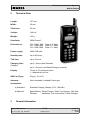
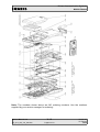
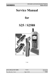
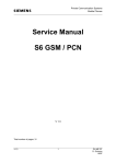
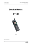
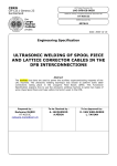
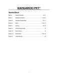
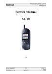
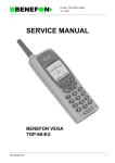
Private Communication Systems Mobile Phones Service Manual for C10 / C11 / C12 V 1.0 Service Manual C1x Sm_C1x_lvl2_v10_w97.doc V 1.0 Page 1 of 23 PN MP ST R. Fleuren 09/98 Private Communication Systems Mobile Phones 1 Table of Contents 1 TABLE OF CONTENTS....................................................................................................................................2 2 TECHNICAL DATA...........................................................................................................................................3 3 GENERAL INFORMATION.............................................................................................................................3 4 MECHANICAL CONCEPT...............................................................................................................................4 4.1 C1X MECHANICAL DRAWING .............................................................................................................................4 4.2NECESSARY TOOLS...........................................................................................................................................6 4.3 DISASSEMBLING THE C1X................................................................................................................................6 4.4 ASSEMBLING THE C1X....................................................................................................................................9 4.5 HANDSET DATECODES...................................................................................................................................12 5 HARDWARE CONCEPT .................................................................................................................................................................................12 5.1 BLOCK DIAGRAM..........................................................................................................................................12 5.2 HARDWARE DESCRIPTION...............................................................................................................................14 5.3 POWER SUPPLY CONCEPT...............................................................................................................................14 5.4 OVERVOLTAGE CONDITIONS ...........................................................................................................................16 6 SOFTWARE PROGRAMMING.....................................................................................................................17 6.1 DESCRIPTION OF SOFTWARE BOOTING .......................................................................................................................................................................17 6.2 LANGUAGE GROUPS......................................................................................................................................17 7 BATTERY..........................................................................................................................................................18 7.1 SPECIFICATION..............................................................................................................................................18 7.2 CHARGING...................................................................................................................................................19 7.3 SHORT CIRCUIT PROTECTION...........................................................................................................................19 7.4 DEEP DISCHARGE.........................................................................................................................................20 7.5BATTERY DATECODES.....................................................................................................................................21 8 UNBLOCKING .................................................................................................................................................22 8.1 SIEMENS HOTLINE.........................................................................................................................................22 8.2 INTERNET SOLUTION.......................................................................................................................................23 Service Manual C1x Sm_C1x_lvl2_v10_w97.doc V 1.0 Page 2 of 23 PN MP ST R. Fleuren 09/98 Private Communication Systems Mobile Phones 2 Technical Data Length: 137 mm Width: 55 mm Thickness: 22 mm Volume: 149 cm³ Weight: 165 g Standards: GSM Phase 2 Performance: C10: GSM 900, Class 4 (2 Watt) C11: GSM 1800, Class 1 (1 Watt) C12: GSM 1900, Class 1 (1 Watt) Power supply: NiMH 700 mAh Standby time: Up to 80 hours Talk time: Up to 5 hours. Charging time: Charger) up to 7 hours (with Standard up to 1.5 hours (with Rapid Charger, optional) Display: 3 lines of 12 characters each + 1 dedicated icon-line SIM Card Type: Plug-In, 3V or 5V Antenna: Non-retractable, Lambda/2 helix type Accessories: 3 a) Standard: Standard Charger, Battery (3.6V, 700mAh) bI Optional: Spare Battery, Rapid Charger, Desk Top Charger, Belt Clip, Portable Handsfree, Car Accessories, Travel Charger General Information Service Manual C1x Sm_C1x_lvl2_v10_w97.doc V 1.0 Page 3 of 23 PN MP ST R. Fleuren 09/98 Private Communication Systems Mobile Phones With the C1x (C10, C11 and C12) the first series of the new C class of Siemens Mobiles are offered to the customer. The intention of this class is to offer entry-level mobile phones for the mass consumer market. One of the main differences is the new type of display used: It is an alphanumeric display which offers 3 lines of text (12 characters each) plus a dedicated icon-line to access the different menues. Quick-DialList 4 SMS Voicemail Ringer Phonebook Call List Setup Mechanical Concept Note: All part numbers refer to mechanical drawing in section 4.1! The mechanical concept of the C1x mobiles is similar to the one of S6 and E10. The C1x consists of two boards, the RF & Control module (1000) and the user interface (MMI board, 1010). The connection between these two boards is not established by a normal connector with plug-in contacts, but by a special interconnector (1210) embedded into a shielding frame (1080). This interconnector is upholding the connection through the pressure implied on it by the housing. Caution: Be careful when assembling the interconnector. Avoid any kind of dust or dirt because it will affect the contacts of the interconnector. On the MMI board there are no exchangeable components. In opposite to the MMI board of S6 and E10 there is no ringer on the MMI. The ringer (1220) is placed in the shielding cover (1090) and connected to the RF&Control module (1000) by a plug and a cable. Because the Molex connector is not located at the bottom of the telephone but on it’s top, there is no need anymore for RF cable mounted to the MMI board and for a RF plug neither. The antenna (1150) is not screwed into the lower case shell, but it is a plug-in type. The keypad (1050), the loudspeaker (1140), the microphone (1130), the dust protection frame (1070) and the display window (1060) are mounted into the upper case shell (1020). Make sure that the microphone contact springs are not damaged when mounting. When turning in the screws (1160 and 1170) make sure that the right torque is used (0.25 0.05)Nm, because this will have an effect on the contacts of the interconnector. 4.1 C1X mechanical drawing Service Manual C1x Sm_C1x_lvl2_v10_w97.doc V 1.0 Page 4 of 23 PN MP ST R. Fleuren 09/98 Private Communication Systems Mobile Phones Note: The numbers shown above are NO ordering numbers. Use the numbers supplied by your service manager for ordering! Service Manual C1x Sm_C1x_lvl2_v10_w97.doc V 1.0 Page 5 of 23 PN MP ST R. Fleuren 09/98 Private Communication Systems Mobile Phones 4.2 Necessary tools For disassembling the SL10 the following tools are mandatory: 4.3 Disassembling the C1X Attention: ESD regulations have to be followed! 1. First remove the battery lid and the battery below it. 2. Remove the SIM card rack with the SIM card. 3. Then you pull the antenna out and remove the connector cover. 4. Remove the four cylinder-head screws in the battery compartment. 5. Release the catches in the battery compartment, lift the lower housing section and push it forwards and out (see figures below). Service Manual C1x Sm_C1x_lvl2_v10_w97.doc V 1.0 Page 6 of 23 PN MP ST R. Fleuren 09/98 Private Communication Systems Mobile Phones 6. Remove the card reader from the recess in the sreen lid. 7. Then loosen the ringer plug-in connector on the radio and control module and remove the ringer afterwards. 8. Unscrew the five cylinder-head screws in the screen lid and remove the screen lid. 9. Remove the RF- and control modul. 10.Remove the battery contacts. Service Manual C1x Sm_C1x_lvl2_v10_w97.doc V 1.0 Page 7 of 23 PN MP ST R. Fleuren 09/98 Private Communication Systems Mobile Phones 11.Then you remove the interconnector joined to it. screen frame and the 12.Lift off the MMI-board from the upper housing section. 13.Then lift the dust protection frame and display glass out of the upper housing section. 14.Finally remove keypad mat, loudspeaker microphone from the upper housing section. Service Manual C1x Sm_C1x_lvl2_v10_w97.doc V 1.0 Page 8 of 23 and PN MP ST R. Fleuren 09/98 Private Communication Systems Mobile Phones 4.4 Assembling the C1X Attention: ESD regulations have to be followed! 1. First you place the microphone and the loudspeaker in the upper housing section. 2. Place the keypad mat and the display glass in the upper housing section and put the dust protection frame on the display window. Attention: The foam side of the frame has to face the MMI-board. 3. Put the interconnector in the screen frame and place the screen frame on top of the MMI. 4. Place the MMI board in the upper housing section. 5. Place the battery contacts in above the MMI board by inserting them into the appropriate holes in the upper housing section. 6. Now put the RF- and control module on the screen frame. Service Manual C1x Sm_C1x_lvl2_v10_w97.doc V 1.0 Page 9 of 23 PN MP ST R. Fleuren 09/98 Private Communication Systems Mobile Phones 7. Put the screen lid on the RF- and control module and fasten it with the five cylinderhead srews. 8. Place the ringer in the recess in the sreen lid and plug in the connector on the RF- and control module. 9. Insert the card reader in the recess in the screen lid. 10. Close the telephone by placing the lower housing secton on at an angle and pushing it backwards and down (see figures A – D below). Make shure that the two catches in the battery compartment are fixed properly (see figure E). A C B D E 11. Screw the four cylinderhead screws into the battery department. Service Manual C1x Sm_C1x_lvl2_v10_w97.doc V 1.0 Page 10 of 23 PN MP ST R. Fleuren 09/98 Private Communication Systems Mobile Phones 12. Now you push the antenna in (figure A). Fasten the connector cover by hooking it into the lower housing section, and snapping it down until it locks in the upper housing section (figure B). A B 13. Insert the SIM card rack together with the SIM card. 14. Finally you insert the battery and close the battery compartment with the battery lid. 15. Now you have assembled the phone completely. Service Manual C1x Sm_C1x_lvl2_v10_w97.doc V 1.0 Page 11 of 23 PN MP ST R. Fleuren 09/98 Private Communication Systems Mobile Phones 4.5 Handset Datecodes Siemens is using the industrial standard DIN EN 60062 to indicate the production / service dates. The code is printed on the IMEI sticker located in the battery compartment. YY = Datecode The first character of the datecode indicates the year of production: F H J K = 1995 = 1996 = 1997 = 1998 The second character indicates the month of production: 1-9 = january to september O = october N = november D = december Example: “JO” means that the set was produced in october of 1997. 5 Hardware Concept 5.1 Block Diagram Service Manual C1x Sm_C1x_lvl2_v10_w97.doc V 1.0 Page 12 of 23 PN MP ST R. Fleuren 09/98 Private Communication Systems Mobile Phones Service Manual C1x Sm_C1x_lvl2_v10_w97.doc V 1.0 Page 13 of 23 PN MP ST R. Fleuren 09/98 Private Communication Systems Mobile Phones 5.2 Hardware Description The handset consists of five major integrated circuits: 1) HiGOLD (PMB 2800) This IC is a combination of microprocessor and signalprocessor. The microprocessor is responsible for controlling the keyboard, SIM-Card, EEPROM, Flash and RAM. Furthermore it controls the power up/power down of the RF module and sets the amplification of the PA. The signal processor is responsible for processing the Rx I/Q signals (filtering, equalizing, speech and channel decoding). Furthermore it does the speech and channel encoding and the GSMK modulation of the Tx I/Q signals. 3) GAIM (PMB 2905) The GAIM provides the interface between the analogue signals (I/Q, voiceband, PAcontrol) and its digital representation. 4) Receiver Circuit (PMB 2409) This circuit provides the following main functionalities: a) Low Noise Amplifier (LNA) with a fixed amplification of +20dB to amplify the input RF signal. b) Mixer to mix down the RF signal to the Intermediate Frequency (IF) c) Programmable IF amplifier with a dynamic range of 60dB ( -10dB ... +50dB in steps of 2dB) d) Mixer to mix down the IF signal to the baseband, generating and inphase (I) and a quadrature (Q) signal. e) Offset compensation for the I/Q signals. 5) Transmitter Circuit PMB 2240/45 This circuit provides the IF synthesizer, the I/Q modulator, prescalers to regulate the RF synthesizer and a buffer stage to feed the PA. The antenna switch is mechanical, located in the Molex connector. TH 5.3 Power Supply Concept Service Manual C1x Sm_C1x_lvl2_v10_w97.doc V 1.0 Page 14 of 23 PN MP ST R. Fleuren 09/98 Private Communication Systems Mobile Phones The C1x has two main power inputs (see Blockdiagram): 1) Battery Voltage (3.6 Volts) connected at the battery contacts 2) Charging Voltage (6.5 Volts) delivered by a) The plug-in charger at the charging plug b) The car kit through the charging connection at the Molex connector c) The desktop charger through the contacts at the outer ends of the Molex connector. Since the battery voltage is supplying the power supply asic, it is always needed to operate the phone. You cannot switch on the handset if the battery voltage is not present. Blockdiagram C1x Power Supply VCC_DD +3.6 V Batt+ +6.0 V Power VDD Control Switching Regulator +6.0 V RF Supply Control Linear Regulator +2.8 V Logic Supply Charging Control 1A Ignition Watchdog ON_OFF Button C1x Power Supply ASIC Power Detection (to µP) SIM Supply RESET Charging On (from µP) From the 3.6 V battery voltage, all other supply voltages of the C1x are derived, controlled by the power supply ASIC. The VCC_DD voltage is used to supply external accessories through the Molex connector at the top of the telephone. The RF module needs 6.0 V for its PA, this voltage is generated by a step-up converter. The logic module uses 2.8 V, generated by a simple linear regulator. Service Manual C1x Sm_C1x_lvl2_v10_w97.doc V 1.0 Page 15 of 23 PN MP ST R. Fleuren 09/98 Private Communication Systems Mobile Phones Furthermore the ASIC generates the supply voltage for the SIM-Card and the RESET signal for the logic devices. The ASIC also checks the presence of the watchdog signal from the µP and provides the switching on functionality (ON_OFF button or Ignition signal). During testing ist is advisable to use a battery dummy, connected to a power supply delivering +4V, max 3A. Make sure that you connect the battery dummy with the right polarity, the red plug to +4V and the blue plug to ground. If you use a voltage higher than +7V, or with wrong polarity, the phone can be destroyed! 5.4 Overvoltage Conditions a) Battery Voltage: If the supply voltage rises above 6.2 Volts, the phone will switch off and it cannot be switched on again before the voltage is lower than 6.2 Volts. If the supply voltage rises above 7 Volts the phone can be destroyed. b) Charging Current: ➣ ➣ The charging current must not rise above 1 A or the phone (fuse) will be inoperable, meaning that charging the battery will not be possible anymore. Be careful with foreign accessories or chargers! Make sure that the charging current is limited to a value below 1A! Service Manual C1x Sm_C1x_lvl2_v10_w97.doc V 1.0 Page 16 of 23 PN MP ST R. Fleuren 09/98 Private Communication Systems Mobile Phones 6 Software programming The software of the C1x handset is programmed directly from a PC using a bootadapter as an interface beetween serial port of the PC and the mobile. 6.1 Description of software booting Connect COM-port of PC to the bootadapter using the enclosed RS232 cable. ˆ Afterwards plug in AC-Adapter: If connected correctly the “Power” lamp will be active. Switch off the C1x handset and connect it to the 9 boot adapter. Bootadapter RS-232 X Copy bootsoftware to the PC and follow the instructions in the file “readme.txt”. Connection Cable AC-Adapter Ordering number of Bootadapter: L24857-F1006-A30 The bootadapter comes complete with ACAdapter, RS-232 and handset connection cable. 6.2 Language Groups Since the C1x has a big memory, a lot of languages fit into one handset software. That’s why there is only one language group at the moment. More may be defined later. Catalan Dutch French Hungar Malayian Portu Swedish Cestina English German Inggris Norsk Russian Turkish Danish Finnish Greek Italian Polish Spanish Attention: This information is subject to change! Contact your service coordinator for the latest update and ordering numbers. Service Manual C1x Sm_C1x_lvl2_v10_w97.doc V 1.0 Page 17 of 23 PN MP ST R. Fleuren 09/98 Private Communication Systems Mobile Phones 7 Battery 7.1 Specification The C1x battery is a NiMH type with a voltage of 3.6 Volts and a capacity of 700 mAh. Suppliers are Varta and Maxell. You can easily recognize the manufacturer by the colour of the battery cells: Varta’s cells are of a green colour, Maxell’s ones are bluish. The connections BATT+ and GND are used to supply the mobile. BATT+ GND Insertion of battery: If the battery would be inserted into the telephone the wrong way round, the phone would be destroyed because of inverted polarity. To prevent this, at both sides of the bottom of the battery there are different mechanical guides which match there respective counterparts in the battery compartment of the telephone. Service Manual C1x Sm_C1x_lvl2_v10_w97.doc V 1.0 Page 18 of 23 PN MP ST R. Fleuren 09/98 Private Communication Systems Mobile Phones 7.2 Charging The battery can only be charged if inserted into the telephone. The charging process is completely controlled by the mobile. Different kinds of Siemens chargers out of the accessory program for C1x models can be used for this task: a) Standard charger b) Quick charger c) Desk top charger (This device is not really a charger but a stand for the mobile, where Standard- , Quick- or Travel charger are connected to) d) Travel charger e) Car charger Attention: Charging the battery can be impossible, if the temperature is too high (e.g. in car use during summer) or too low. This is to prevent the battery from being damaged during fast charge process. To enable the charging process again, battery and phone only needs to cool down/warm up. A replacement of battery is not necessary. 7.3 Short Circuit Protection CAUTION: Avoid short circuit of battery ! The battery is not short-circuit protected by an electronic fuse like e.g. in S10. Inside the battery a polyswitch is protecting the battery cells from a too high output current. Schematic of the battery: Service Manual C1x Sm_C1x_lvl2_v10_w97.doc V 1.0 Page 19 of 23 PN MP ST R. Fleuren 09/98 Private Communication Systems Mobile Phones 7.4 Deep Discharge In case of a deeply discharged battery, the phone can not be turned on and the normal charging process can not be started. In this case, charging the battery is divided into two different steps, which have to be run subsequently: a) Trickle charge Trickle charge mode is automatically started if the battery voltage is below a certain value when the charger is connected to the mobile. This mode is not terminated automatically but has to be terminated by disconnecting the charger. Trickle charge mode has to last until the battery voltage has exceeded a certain level. During trickle charge the charging symbol will not be visible and the telephone can not be turned on. Action: Insert battery into handset and connect travel charger to the telephone. Wait for appr. 1 hour, then disconnect and reconnect charger. If the battery voltage is high enough again, the charging symbol will come up. If the battery is discharched very deeply, the symbol may not come up and the trickle charge time possibly has to be extended up to 24 hours. b) Normal charge When the battery voltage is above the a.m. value (e.g. by trickle charge) the mobile will start the normal charging mode. Action: Connect charger to the telephone. The charging symbol will come up as an indication that the normal charging process has been started by the mobile. Service Manual C1x Sm_C1x_lvl2_v10_w97.doc V 1.0 Page 20 of 23 PN MP ST R. Fleuren 09/98 Private Communication Systems Mobile Phones 7.5 Battery Datecodes There are two different suppliers of the C1x batteries and they use different kinds of codes to give information about production date: a) Maxell batteries The datecode printed on the battery looks like this: K 7 08 20 M Explanation: K 7 08 20 M = Year of production (1998=K, 1999=L) = Month of production (Jan=1, Feb=2, .....Oct=O, Nov=N, Dec=D) = Day of production (1st =1, 2nd =2, 3rd =3,........, 31st=31) = Week of cell-production = Factory code (M=UK, E= Germany) Example: This battery was produced on July 8th of 1998! K 7 08 20 M b) Varta batteries The datecode printed on the battery looks like this: TOS 8 G9 VA 1 Explanation: TOS 8 G 9 VA 1 = Battery cells supplied by Toshiba = Revision level = Year of production (1997=J, 1998=K, 1999=L) = Month of production (Jan=1, Feb=2, .....Oct=O, Nov=N, Dec=D) = Varta (battery manufacturer) = Place of manufacturing (1=Germany ,2= Novibor, Czech Republic) Example: TOS 8 K4 VA 1 Service Manual C1x Sm_C1x_lvl2_v10_w97.doc This battery was produced in april of 1998! V 1.0 Page 21 of 23 PN MP ST R. Fleuren 09/98 Private Communication Systems Mobile Phones 8 Unblocking If the phone is disabled due to a wrong entry of the phonecode (not PIN1, PIN2, network code or service provider code!) it can only be resetted by entering the right unblocking code. This unblocking code is derived from the IMEI number of the mobile and can only be calculated in two different ways: 8.1 Siemens Hotline You can retreive the code from our hotline personell in Germany. If you need unblocking codes just send a fax with the IMEI numbers to: Siemens AG PN MP SH World Service Center Bocholt, Germany Fax: +49 2871 91 3007 Please use the appropriate form provided by your Siemens service coordinator. Service Manual C1x Sm_C1x_lvl2_v10_w97.doc V 1.0 Page 22 of 23 PN MP ST R. Fleuren 09/98 Private Communication Systems Mobile Phones 8.2 Internet solution As an alternative to the a.m. procedure, since november 1997 an internet solution is offered to the LSO. It is a password protected internet homepage where you can enter the IMEI number of the affected handset. The page will then present Master Phone Codes, Master Network Codes and Master Service Provider Codes (if applicable to the relevant telephone). If you do not have access to this tool up to now, please contact your Siemens service manager for details. Service Manual C1x Sm_C1x_lvl2_v10_w97.doc V 1.0 Page 23 of 23 PN MP ST R. Fleuren 09/98