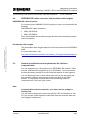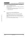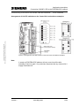
1
Drive System Application
Commissioning of the Control Unit CU230P-2 DP
with PROFIBUS
Application description
for SINAMICS G120 and MICROMASTER 440
Warranty, liability and support
Commissioning of the Control Unit CU230P-2 DP with PROFIBUS
Copyright © Siemens AG 2009 All rights reserved
PDF_Commissioning_of_CU230P_2_DP_with Profibus_en_V1.doc
Note
ID-No: 35934076
The Application Examples are not binding and do not claim to be
complete regarding the circuits shown, equipping and any eventuality.
The Application Examples do not represent customer-specific solutions.
They are only intended to pro-vide support for typical applications. You
are responsible in ensuring that the de-scribed products are correctly
used. These Application Examples do not relieve you of the responsibility
in safely and professionally using, installing, operating and servicing
equipment. When using these Application Examples, you recognize that
Siemens cannot be made liable for any damage/claims beyond the
liability clause described. We reserve the right to make changes to these
Application Examples at any time without prior notice. If there are any
deviations between the recommendations provided in these Application
Examples and other Siemens publications - e.g. Catalogs - then the
contents of the other documents have priority.
Warranty, liability and support
We do not accept any liability for the information contained in this
document.
Any claims against us - based on whatever legal reason - resulting from the
use of the examples, information, programs, engineering and performance
data etc., described in this Application Examples shall be excluded. Such
an exclusion shall not apply in the case of mandatory liability, e.g. under
the German Product Liability Act (“Produkthaftungsgesetz”), in case of
intent, gross negligence, or injury of life, body or health, guarantee for the
quality of a product, fraudulent concealment of a deficiency or breach of a
condition which goes to the root of the contract (“wesentliche
Vertragspflichten”). However, claims arising from a breach of a condition
which goes to the root of the contract shall be limited to the foreseeable
damage which is intrinsic to the contract, unless caused by intent or gross
negligence or based on mandatory liability for injury of life, body or health
The above provisions does not imply a change in the burden of proof to
your detriment.
Copyright© 2009 Siemens A&D. It is not permissible to transfer or
copy these Application Examples or excerpts of them without first
having prior authorization from Siemens A&D in writing.
If you have any recommendations relating to this document then please
send them to us at the following e-mail address:
mailto:[email protected]
Version 1
Issue May 2009
2/33
Preposition
Commissioning of the Control Unit CU230P-2 DP with PROFIBUS
ID-No: 35934076
Preposition
Aim of the application
This application was created in order to provide the user with an easy
introduction to the subject of commissioning the CU230P-2 DP control unit
with PROFIBUS interface.
This application contains general instructions on how to connect the
CU230P-2 DP to a PROFIBUS DP network.
The application describes each of the steps involved in setting up an S7
project to control a SINAMIC G120 with the CU230P-2 DP via PROFIBUS,
and how to control the inverter using a variable table.
Copyright © Siemens AG 2009 All rights reserved
PDF_Commissioning_of_CU230P_2_DP_with Profibus_en_V1.doc
Scope
The following core issues are discussed in this application:
•
Instructions for connecting the CU230P-2 DP to a PROFIBUS DP
network.
•
Commissioning the CU230P-2 DP with PROFIBUS interface
Exclusion
This description can be applied for SINAMICS G120 frequency inverters
with Control Units CU230P-2 DP.
•
This application does not include any description of the following
•
The SIMATIC STEP 7 programming tool
•
The basic commissioning of the frequency inverter
•
Commissioning higher-level controls
It is assumed that readers have basic knowledge about these two subjects.
Reference to the Automation and Drives Service & Support
This article is from the Internet Application Portal of the Automation and
Drives Service & Support. You can go directly to the download page of this
document using this link.
http://support.automation.siemens.com/WW/view/en/35934076
Version 1
Issue May 2009
3/33
Application description
Table of Contents
Commissioning of the Control Unit CU230P-2 DP with PROFIBUS
ID-No: 35934076
Table of Contents
Table of Contents ......................................................................................................... 4
Copyright © Siemens AG 2009 All rights reserved
PDF_Commissioning_of_CU230P_2_DP_with Profibus_en_V1.doc
Application description................................................................................................ 6
1
Description ...................................................................................................... 6
2
2.1
2.2
2.3
2.4
2.5
Connecting CU230P-2 DP to the PROFIBUS DP network ........................... 8
Integrating an inverter into the PROFIBUS DP fieldbus system ....................... 8
PROFIBUS DP cable connector and permitted cable lengths .......................... 9
General specifications and requirements for fault-free communication ............ 9
Setting the PROFIBUS DP address ............................................................... 10
Arrangement of the DIP switches on the Control Unit and address
examples.................................................................................................... 11
Communication settings for PROFIBUS DP ................................................... 12
3
3.1
3.2
Prerequisites ................................................................................................. 13
Hardware components.................................................................................... 13
Software components ..................................................................................... 14
4
4.1
4.2
Configuration and wiring ............................................................................. 15
Hardware configuration................................................................................... 15
Setting the PROFIBUS-DP address of the CU230P-2 DP.............................. 15
5
Configuring the CU230P-2 DP ..................................................................... 16
6
Set PG/PC interface ...................................................................................... 17
7
Create a project and add a SIMATIC 300 station ....................................... 18
8
8.1
8.2
8.3
Creating the hardware configuration .......................................................... 19
Creating the SIMATIC hardware..................................................................... 19
Creating the PROFIBUS interface .................................................................. 21
Inserting the SINAMICS G120........................................................................ 25
Installing the GSD file................................................................................. 25
Setting-up the frequency inverter ............................................................... 26
Selecting the telegram ............................................................................... 28
Save and compile ........................................................................................... 29
Download to Module ....................................................................................... 29
8.4
8.5
9
Creating and Configuring Modules ............................................................. 30
Modify organisation block OB1 .................................................................. 30
Add variable table ...................................................................................... 30
Load into CPU............................................................................................ 30
10
Controlling the drive..................................................................................... 31
11
Other links ..................................................................................................... 32
Appendix and references........................................................................................... 33
Version 1
Issue May 2009
4/33
Application description
Table of Contents
Commissioning of the Control Unit CU230P-2 DP with PROFIBUS
References .................................................................................................... 33
Internet link data ............................................................................................. 33
History............................................................................................................. 33
Copyright © Siemens AG 2009 All rights reserved
PDF_Commissioning_of_CU230P_2_DP_with Profibus_en_V1.doc
12
12.1
12.2
ID-No: 35934076
Version 1
Issue May 2009
5/33
Application description
Description
Commissioning of the Control Unit CU230P-2 DP with PROFIBUS
ID-No: 35934076
Application description
This section provides an overview of how to commission a SINAMICS
G120 with a CU230P-2 DP control unit and PROFIBUS.
1
Description
The CU230 is a Control Unit that has been optimized for pumps and fans. It
can be operated with all power units of the PM240 and PM250 series.
Copyright © Siemens AG 2009 All rights reserved
PDF_Commissioning_of_CU230P_2_DP_with Profibus_en_V1.doc
The CU230 Control Units are available in three versions:
•
CU230P HVAC with USS interface via RS485
•
CU230P CAN with CANopen interface
•
CU230P DP with PROFIBUS DP interface
Figure 1-1 CU230P-2 DP with PROFIBUS DP interface, doors closed and open
Version 1
Issue May 2009
6/33
Application description
Description
Commissioning of the Control Unit CU230P-2 DP with PROFIBUS
ID-No: 35934076
Copyright © Siemens AG 2009 All rights reserved
PDF_Commissioning_of_CU230P_2_DP_with Profibus_en_V1.doc
They can be commissioned either using the STARTER commissioning
software or using the optional "Intelligent Operator Panel - IOP“.
Figure 1-2 Intelligent Operator Panel (IOP)
This application describes the commissioning of the CU230P-2 DP with
PROFIBUS DP interface.
It provides general instructions on how to connect the CU230P-2 DP to a
PROFIBUS DP network, and explains how to commission a SINAMICS
G120 with CU230P-2 DP and SIMATIC S7.
It is assumed for the purpose of this application that the motor and inverter
(the power module and the control unit) have been assembled and that the
inverter has undergone the quick commissioning process.
The information required here can be found in the operating instructions for
the SINAMICS G120 and the CU230P-2 DP control units.
Version 1
Issue May 2009
7/33
Application description
Connecting CU230P-2 DP to the PROFIBUS DP network
Commissioning of the Control Unit CU230P-2 DP with PROFIBUS
ID-No: 35934076
2
Connecting CU230P-2 DP to the PROFIBUS DP
network
2.1
Integrating an inverter into the PROFIBUS DP fieldbus system
Copyright © Siemens AG 2009 All rights reserved
PDF_Commissioning_of_CU230P_2_DP_with Profibus_en_V1.doc
To integrate the inverter into the PROFIBUS DP fieldbus system, a 9-pin
sub-D connector conforming to the PROFIBUS standard can be found on
the underside of the CU230P-2 DP control unit. The terminals in this
connector are short-circuit proof and potential-free.
Figure 2-1 Sub-D connector on the CU230P-2 DP
You will find the pin assignments in the following table:
Table 2-1 Pin assignments for the 9-pin sub D connector (socket)
Contact
Version 1
Designation
Description
1
PE/shield
Ground connection
2
---
---
3
DPB
Data P receive/transmit (B/B’)
4
RTS
Control signal
5
0V
Reference potential for PROFIBUS data
(C/C’)
6
5V
Supply voltage plus
7
---
---
8
DPA
Data N receive/transmit (A/A’)
9
---
---
Enclosure
PE/shield
Cable shield
Issue May 2009
8/33
Application description
Connecting CU230P-2 DP to the PROFIBUS DP network
Commissioning of the Control Unit CU230P-2 DP with PROFIBUS
2.2
ID-No: 35934076
PROFIBUS DP cable connector and permitted cable lengths
PROFIBUS DP cable connector
For connecting the SINAMICS G120 frequency inverter, we recommend the
following
PROFIBUS DP cable connectors:
•
6GK1 500-0FC00
•
6GK1 500-0EA02
They are equipped with a switch through which the bus terminating resistor
can be connected.
Copyright © Siemens AG 2009 All rights reserved
PDF_Commissioning_of_CU230P_2_DP_with Profibus_en_V1.doc
Permissible cable lengths
The permissible cable lengths depend on the baud rate and the PROFIBUS
cable.
For more information, visit:
(http://www.automation.siemens.com/net/html_76/support/printkatalog.htm)
2.3
General specifications and requirements for fault-free
communication
You can integrate up to 126 stations into a PROFIBUS DP network. These
must be subdivided into segments of up to 32 stations. You must activate
the bus terminating resistor for the first and last stations of each segment.
You can disconnect one or more slaves from the bus (by unplugging the
bus connector) without interrupting the communication for the other
stations. It is important to ensure that a bus terminating resistor is
connected to the "first" and "last" nodes.
Note
Communication with the controller, even when the line voltage is
switched off
You will have to supply the Control Unit with 24 V DC on terminals 31 and
32 if you require communication to take place with the controller when the
line voltage is switched off.
Version 1
Issue May 2009
9/33
Application description
Connecting CU230P-2 DP to the PROFIBUS DP network
Commissioning of the Control Unit CU230P-2 DP with PROFIBUS
2.4
ID-No: 35934076
Setting the PROFIBUS DP address
Before the PROFIBUS DP interface is used, the address of the node point
(inverter) must be set.
The following methods are available for setting the PROFIBUS DP address:
•
Using the address switch on the Control Unit
•
Using parameter p0918
Note
Important notes for setting the PROFIBUS address
The address setting on the DIP switch takes priority over the p0918
settings.
Copyright © Siemens AG 2009 All rights reserved
PDF_Commissioning_of_CU230P_2_DP_with Profibus_en_V1.doc
The PROFIBUS DP address can only be set using p0918 when the
address 0 is set on the DIP switches of the Control Unit (factory setting).
When the address switch is set to a value ≠ 0, the setting in p0918 is
ignored.
The valid address range for Siemens controllers is 1 to 125. Addresses 126
and 127 cannot be used with SIMATIC controllers.
Version 1
Issue May 2009
10/33
Application description
Connecting CU230P-2 DP to the PROFIBUS DP network
Commissioning of the Control Unit CU230P-2 DP with PROFIBUS
ID-No: 35934076
Copyright © Siemens AG 2009 All rights reserved
PDF_Commissioning_of_CU230P_2_DP_with Profibus_en_V1.doc
Arrangement of the DIP switches on the Control Unit and address examples
Figure 2-2 Arrangement of the DIP switches on the Control Unit and address examples
Note
A newly set PROFIBUS DP address will only come into effect after
switching off and on again. It is particularly important that any external 24 V
supply is switched off.
Version 1
Issue May 2009
11/33
Application description
Connecting CU230P-2 DP to the PROFIBUS DP network
Commissioning of the Control Unit CU230P-2 DP with PROFIBUS
2.5
ID-No: 35934076
Communication settings for PROFIBUS DP
PROFIBUS DP parameters
You can fully integrate your inverter with a CU230P-2 DP Control Unit into
a PROFIBUS communication system without the need for any PROFIBUSspecific parameter settings when the following preconditions are met:
•
The PROFIBUS address is set using a DIP switch
•
The communication procedure uses standard telegram 1
If you want to modify the communication settings, the parameters that you
can use to make changes are listed in the table below.
Table 2-2 PROFIBUS DP parameters
Copyright © Siemens AG 2009 All rights reserved
PDF_Commissioning_of_CU230P_2_DP_with Profibus_en_V1.doc
Parameter
Version 1
Description
P0918
PROFIBUS address
P0922
Selection of the PROFIBUS standard telegram
P2038
Selection of the communication profile (PROFIdrive profile 4.1 /
VIK NAMUR)
P2042
Selection of the profile code for the controller (PROFIdrive profile
4.1 / VIK NAMUR)
r2050
Set-point source for process data (BICO)
P2051
Actual values for process data (BICO)
P2030
Fieldbus interface telegram selection
P2037
PROFIdrive processing mode
P2040
Fieldbus telegram off time
P2044
PROFIdrive fault delay for setpoint
P2047
PROFIBUS additional monitoring time
r2054
Diagnostics of the communication module
r2055
PROFIBUS diagnostics - standard
r2075
PROFIdrive diagnostics telegram offset
P2079
PROFIdrive PZD extended telegram selection
Issue May 2009
12/33
Application description
Prerequisites
Commissioning of the Control Unit CU230P-2 DP with PROFIBUS
3
Prerequisites
3.1
Hardware components
ID-No: 35934076
Table 3-1 Hardware components
Component
Order No.
[MLFB]/ordering data
Type
No.
Manufacturer
SIEMENS
S7 control
Power supply
PS307 5A
6ES7307-1EA00-0AA0
1
S7-F CPU
CPU 317F-2 PN/DP
6ES7317-2FK13-0AB0
1
Memory Card
MMC 8 MB
6ES7953-8LP11-0AA0
1
SINAMICS G120 Control Unit
CU230P-2 DP
6SL3243-0BA30-1PA0
1
SINAMICS G120 Power Module
PM240
6SL3224-0BE13-7UA0
1
Intelligent Operator Panel IOP
6SL3255-0AA00-4AA0
1
Copyright © Siemens AG 2009 All rights reserved
PDF_Commissioning_of_CU230P_2_DP_with Profibus_en_V1.doc
Drive
Operator Panel IOP
*
SIEMENS
PROFIBUS
PROFIBUS Cable 3 m
SIMATIC NET, PB FC
Standard Cable GP, 2-wire,
shielded, min. ordering
quantity: 20 m sold by the
meter
6XV1830-0EH10
1
PB connector
PB FC RS 485 PLUG 180,
PB connector w. fast connect
connector
6GK1500-0FC00
2
PB connector
SIMATIC DP, bus connector
for PROFIBUS up to 12
Mbit/s with tilted outgoing
cable
6ES7972-0BA41-0XA0
2
SIEMENS
Motor / Line
Motor
Asynchronous motor
1LA7060-4AB10
1
Motor cable, 1.5 m
Motor cable
6ES7194-1LA01-0AA0
1
Line supply feeder cable
Line supply feeder cable
-
1
-
PG/PC
SIMATIC Field PG M
6ES7712-1BB10-0AG2
1
SIEMENS
SIEMENS
PG/PC
Note:
The functionality was tested using the specified hardware components.
Similar products can be used that deviate from the list above.
*
The Intelligent Operator Panel IOP is required in order to parameterize the drive. The STARTER
commissioning tool can also be used (refer to the software prerequisites).
Version 1
Issue May 2009
13/33
Application description
Prerequisites
Commissioning of the Control Unit CU230P-2 DP with PROFIBUS
3.2
ID-No: 35934076
Software components
Table 3-2 Software components
Component
SIMATIC STEP 7
STARTER
*
Order No.
[MLFB]/ordering data
No.
Manufacturer
SIEMENS
V5.4 + SP2
6ES7810-4CC08-0YA5
1
V4.2
6SL3072-0AA00-0AG0
or Downloads
1
MS Windows 2000 SP3 / MS
Windows XP / Windows 2003
Server
-
1
Microsoft
Copyright © Siemens AG 2009 All rights reserved
PDF_Commissioning_of_CU230P_2_DP_with Profibus_en_V1.doc
MS Windows
Type
*
The STARTER commissioning tool is required to parameterize the drive. The operator panel
can also be used (refer to the hardware prerequisites).
Version 1
Issue May 2009
14/33
Application description
Configuration and wiring
Commissioning of the Control Unit CU230P-2 DP with PROFIBUS
4
Configuration and wiring
4.1
Hardware configuration
ID-No: 35934076
Copyright © Siemens AG 2009 All rights reserved
PDF_Commissioning_of_CU230P_2_DP_with Profibus_en_V1.doc
Connect all of the devices as shown in Fig. 4-1.
Figure 4-1 Hardware configuration
4.2
Setting the PROFIBUS-DP address of the CU230P-2 DP
Set the PROFIBUS-DP address of the CU230P-2 DP either via the
address switch on the control unit or via parameter p0918.
Version 1
Issue May 2009
15/33
Application description
Configuring the CU230P-2 DP
Commissioning of the Control Unit CU230P-2 DP with PROFIBUS
5
ID-No: 35934076
Configuring the CU230P-2 DP
The CU230P-2 DP control units are preconfigured for use with PROFIBUS,
i.e. PROFIBUS has been selected as the factory setting for the command
and set-point source (P0700 and P1000) and standard telegram 1 has
been selected as the telegram type (P0922).
The IOP or STARTER can be used to check parameters P0700, P1000 and
P0922 in the CU230P-2 DP and, if necessary, adjust them as follows:
Copyright © Siemens AG 2009 All rights reserved
PDF_Commissioning_of_CU230P_2_DP_with Profibus_en_V1.doc
Parameter
No.
Designation
Parameter
value
Note / comments
P0922
Selection of the PROFIBUS
standard telegram
1
1: Standard telegram 1
P0700[0]
Selection of command source
6
6: PROFIBUS
P1000[0]
Selection of frequency setpoint
6
6: PROFIBUS
Table 5-1 Configuring the CU230P-2 DP
Version 1
Issue May 2009
16/33
Application description
Set PG/PC interface
Commissioning of the Control Unit CU230P-2 DP with PROFIBUS
6
ID-No: 35934076
Set PG/PC interface
Open the SIMATIC Manager and set the PG/PC interface. To do this, press
the button "Options -> Set PG/PC Interface…" in the SIMATIC Manager
menu.
Copyright © Siemens AG 2009 All rights reserved
PDF_Commissioning_of_CU230P_2_DP_with Profibus_en_V1.doc
From the list, select the PROFIBUS interface and acknowledge your
selection with "OK".
Figure 6-1 Set PG/PC interface
Acknowledge the alarm "The following access path(s) was (were)
changed: S7ONLINE (STEP 7) => CP5611(PROFIBUS)" with "OK".
Figure 6-2 Acknowledge the alarm
This means that the PROFIBUS interface of your PG/PC can be accessed
from STEP 7.
Version 1
Issue May 2009
17/33
Application description
Create a project and add a SIMATIC 300 station
Commissioning of the Control Unit CU230P-2 DP with PROFIBUS
7
ID-No: 35934076
Create a project and add a SIMATIC 300 station
Copyright © Siemens AG 2009 All rights reserved
PDF_Commissioning_of_CU230P_2_DP_with Profibus_en_V1.doc
Create a new project and add a SIMATIC 300 station to the project by
clicking the "Insert -> Station -> 2 SIMATIC 300 Station" button in the
menu (see Figure 7-1).
Figure 7-1 Adding a SIMATIC 300 station
Version 1
Issue May 2009
18/33
Application description
Creating the hardware configuration
Commissioning of the Control Unit CU230P-2 DP with PROFIBUS
8
Creating the hardware configuration
8.1
Creating the SIMATIC hardware
ID-No: 35934076
Open the hardware configuration by double-clicking the "Hardware" button
(see Figure 8-1).
Copyright © Siemens AG 2009 All rights reserved
PDF_Commissioning_of_CU230P_2_DP_with Profibus_en_V1.doc
Double-click
Figure 8-1 Opening HW-Configuration
Version 1
Issue May 2009
19/33
Application description
Creating the hardware configuration
Commissioning of the Control Unit CU230P-2 DP with PROFIBUS
ID-No: 35934076
In the HW-Config:
•
insert a SIMATIC S7-300 rack into the configuration,
•
and then draw the desired power supply module from the product tree
to slot 1 and the CPU to the slot 2 in the SIMATIC rack.
When you insert the CPU the window for the settings of the Ethernet
interface opens. Close the window with “OK” (Fig. 8-2).
Copyright © Siemens AG 2009 All rights reserved
PDF_Commissioning_of_CU230P_2_DP_with Profibus_en_V1.doc
–
Figure 8-2 Inserting the CPU
Version 1
Issue May 2009
20/33
Application description
Creating the hardware configuration
Commissioning of the Control Unit CU230P-2 DP with PROFIBUS
ID-No: 35934076
Result:
Copyright © Siemens AG 2009 All rights reserved
PDF_Commissioning_of_CU230P_2_DP_with Profibus_en_V1.doc
Double-click
Figure 8-3 HW Config after setting-up the SIMATIC hardware
8.2
Creating the PROFIBUS interface
To create the PROFIBUS interface, double-click on slot 3 – MPI/DP (refer
to Fig. 8-3).
Version 1
Issue May 2009
21/33
Application description
Creating the hardware configuration
Commissioning of the Control Unit CU230P-2 DP with PROFIBUS
ID-No: 35934076
Copyright © Siemens AG 2009 All rights reserved
PDF_Commissioning_of_CU230P_2_DP_with Profibus_en_V1.doc
The properties window of the MPI/DP interface opens (refer to Fig. 84).Select the PROFIBUS interface (Fig. 8-4).
Figure 8-4 Properties of the MPI/DP interface
The next window appears in which a new subnet must be set-up. Now,
select the PROFIBUS address 2 and press on the button "New…" (Fig. 85).
Figure 8-5 Creating a new subnet
Version 1
Issue May 2009
22/33
Application description
Creating the hardware configuration
Commissioning of the Control Unit CU230P-2 DP with PROFIBUS
ID-No: 35934076
In the window “Properties – New subnet PROFIBUS” you can assign a
name to the subnet or leave the default setting.
Copyright © Siemens AG 2009 All rights reserved
PDF_Commissioning_of_CU230P_2_DP_with Profibus_en_V1.doc
Close the window with “OK” (Fig. 8-6).
Figure 8-6 Assign a name to the PROFIBUS subnet
In the properties box, select the subnet PROFIBUS(1) and accept
PROFIBUS address 2 by pressing the "OK" key (Fig. 8-7).
Figure 8-7 Accepting the PROFIBUS address
Version 1
Issue May 2009
23/33
Application description
Creating the hardware configuration
Commissioning of the Control Unit CU230P-2 DP with PROFIBUS
ID-No: 35934076
Result:
Copyright © Siemens AG 2009 All rights reserved
PDF_Commissioning_of_CU230P_2_DP_with Profibus_en_V1.doc
The PROFIBUS (bus) line (DP master system) is displayed in HW Config.
Figure 8-8 HW Config after creating the PROFIBUS interface
Version 1
Issue May 2009
24/33
Application description
Creating the hardware configuration
Commissioning of the Control Unit CU230P-2 DP with PROFIBUS
8.3
ID-No: 35934076
Inserting the SINAMICS G120
Prerequisite
PROFIBUS GSD files for SINAMICS G120 V4.1 must have been installed
in order that the Control Unit CU230P-2 DP can be accessed via
PROFIBUS.
Installing the GSD file
Install the PROFIBUS GSD file via the menu item "Options -> Install GSD
File…" of HW-Config.
Copyright © Siemens AG 2009 All rights reserved
PDF_Commissioning_of_CU230P_2_DP_with Profibus_en_V1.doc
In the window that pops up, select the GSD files that you want to install and
click the "Install" button (see Figure 8-9).
Figure 8-9 Installing the GSD file
Version 1
Issue May 2009
25/33
Application description
Creating the hardware configuration
Commissioning of the Control Unit CU230P-2 DP with PROFIBUS
ID-No: 35934076
Result:
After you have installed the PROFIBUS GSD files the corresponding files
appear in the HW Catalog under the "Standard Profile" in the folder
"PROFIBUS DP\Additional Field Devices\Drives\SINAMICS\ SINAMICS
G120 CU230P-2 DP ".
Setting-up the frequency inverter
Copyright © Siemens AG 2009 All rights reserved
PDF_Commissioning_of_CU230P_2_DP_with Profibus_en_V1.doc
For inserting the SINAMICS G120 you draw the SINAMICS G120
CPU230P-2 DP from the hardware catalog over the Profibus string at the
CPU (Fig. 8-10).
Figure 8-10 Inserting the SINAMICS G120
Version 1
Issue May 2009
26/33
Application description
Creating the hardware configuration
Commissioning of the Control Unit CU230P-2 DP with PROFIBUS
ID-No: 35934076
After inserting the G120 the property window Properties – PROFIBUS
interface SINAMICS G120 CU230P-2 DP opens.
Copyright © Siemens AG 2009 All rights reserved
PDF_Commissioning_of_CU230P_2_DP_with Profibus_en_V1.doc
In this property window set the Profibus address for the CU230P-2 DP to 3
and accept the setting with “OK” (Fig. 8-11).
Figure 8-11 Set the Profibus address for the CU230P-2 DP
Version 1
Issue May 2009
27/33
Application description
Creating the hardware configuration
Commissioning of the Control Unit CU230P-2 DP with PROFIBUS
ID-No: 35934076
Selecting the telegram
Copyright © Siemens AG 2009 All rights reserved
PDF_Commissioning_of_CU230P_2_DP_with Profibus_en_V1.doc
Select “Standard telegram 1” and locate this in the first free slot in the
lower section of the window (Fig. 8-12).
Figure 8-12 Selecting the telegram
Result:
The SINAMICS G120 frequency inverter with the CU230P-2 DP Control
Unit and with standard telegram 1 is configured in HW Config.
Version 1
Issue May 2009
28/33
Application description
Creating the hardware configuration
Commissioning of the Control Unit CU230P-2 DP with PROFIBUS
8.4
ID-No: 35934076
Save and compile
After completing the configuration of the SINAMICS G120 the hardware
configuration must be saved and compiled.
Save and compile your configuration by pressing the
compile“ button (Figure 8-12).
8.5
„Save and
Download to Module
Copyright © Siemens AG 2009 All rights reserved
PDF_Commissioning_of_CU230P_2_DP_with Profibus_en_V1.doc
Now load the hardware configuration into the CPU by clicking the
button "Download to Module" button (Figure 8-12).
Version 1
Issue May 2009
29/33
Application description
Creating and Configuring Modules
Commissioning of the Control Unit CU230P-2 DP with PROFIBUS
9
ID-No: 35934076
Creating and Configuring Modules
To control the drive, the organisation block OB1 must now be modified and
a variable table added to the project.
Modify organisation block OB1
Copyright © Siemens AG 2009 All rights reserved
PDF_Commissioning_of_CU230P_2_DP_with Profibus_en_V1.doc
Add the following entries to OB1 (see Figure 9-1):
Figure 9-1 Text and comments for OB1
Add variable table
Add a variable table using the SIMATIC Manager menu item "Insert -> S7
Block -> 6 Variable Table" (see Figure 9-2).
Figure 9-2 Adding a variable table
In the variable table, add the following entries for flag words MW0, MW2,
MW4 and MW6 (see Figure10-1).
Load into CPU
Then load OB1 into the CPU by clicking the
Version 1
Issue May 2009
"Download" button.
30/33
Application description
Controlling the drive
Commissioning of the Control Unit CU230P-2 DP with PROFIBUS
10
ID-No: 35934076
Controlling the drive
Control word 1 (STW1) and the main set-point (HSW) are sent to the drive
via the PROFIBUS interface. Status word 1 (ZSW1) and the main actual
value (HIW) are received from the drive.
The drive is started by sending the typical control word 047E, followed by
047F (edge of bit 0: ON). In order to stop the drive, word 047E should be
sent to the drive (edge of bit 0: OFF). The control word is sent together with
process data word 1 (PZD1) that should be specified in the variable table
VAT_1 (bit memory word MW0, refer to Fig. 10-1).
Status word 1 (ZSW1) is received from the drive (PZD1) and is transferred
into the bit memory word MW4. The MW4 can be taken from variable table
VAT_1 (refer to Fig. 10-1).
Copyright © Siemens AG 2009 All rights reserved
PDF_Commissioning_of_CU230P_2_DP_with Profibus_en_V1.doc
The main setpoint is sent, together with PZD2 to the drive - and the main
actual value is received from the drive in PZD2. The main set-point should
be specified in the variable table VAT_1 (bit memory word MW2, refer to
Fig. 10-1). The response - the main actual value - is saved in the MW6 and
can be taken from the variable table (refer to Fig. 10-1).
The frequency setpoint and actual value are normalized so that 4000(hex)
corresponds to 50Hz. The highest value that should be sent is 7FFF. The
normalization frequency (reference frequency) can be modified in P2000
(default, 50Hz).
Enter control word 1
Enter main setpoint
Read-out status word 1
Read-out actual
frequency
Figure 10-1 Controlling the drive
Version 1
Issue May 2009
31/33
Application description
Other links
Commissioning of the Control Unit CU230P-2 DP with PROFIBUS
11
ID-No: 35934076
Other links
The following article illustrates how to control the inverter: Article ID
22078757 Function block (FC14) to control a drive inverter via Profibus-DP.
This example illustrates how to quickly and easily connect the inverter to a
SIMATIC S7-300/400 controller via Profibus-DP.
Copyright © Siemens AG 2009 All rights reserved
PDF_Commissioning_of_CU230P_2_DP_with Profibus_en_V1.doc
The following options are illustrated in the program:
•
Sending the IN/OUT command
•
Reversing the inverter
•
Fault acknowledgement
•
Setpoint specification for the inverter
Read the following articles for more information about "Reading and writing
inverter parameters":
1. Reading and writing parameters of the frequency inverters SINAMICS
G120/G120D, ET200S FC and ET200pro via PROFINET and
PROFIBUS
2. How do I control a G120 using the system functions SFC58 and
SFC59?
3. How can I use SFC58 and SFC59 to read parameters from my G120?
Version 1
Issue May 2009
32/33
Appendix and references
References
Commissioning of the Control Unit CU230P-2 DP with PROFIBUS
ID-No: 35934076
Appendix and references
12
References
12.1
Internet link data
This list is in no way complete and only reflects a selection of suitable
references.
Table 12-1
Copyright © Siemens AG 2009 All rights reserved
PDF_Commissioning_of_CU230P_2_DP_with Profibus_en_V1.doc
Subject area
12.2
Title
\1\
Documentation
SINAMICS G120
\2\
Application
Function block (FC14) to control a drive inverter via
Profibus-DP
\3\
Application
Reading and writing parameters of the frequency
inverters SINAMICS G120/G120D, ET200S FC and
ET200pro via PROFINET and PROFIBUS
\4\
FAQ
How do I control a G120 using the system functions
SFC58 and SFC59?
\5\
FAQ
How can I use SFC58 and SFC59 to read parameters
from my G120?
\6\
FAQ
Are there program examples for the Instruction Manual
of the MICROMASTER PROFIBUS option module?
\7\
FAQ
How do I read / write parameters using PROFIBUS on
the MICROMASTER 4 and CU240S/D DP/DP-F and
PROFINET on the CU240S/D PN/PN-F?
\8\
FAQ
For MM 4 and for G120/G120D frequency inverters,
which parameters can be read-out using PZD?
History
Table 12-2 History
Version
V1.0
Version 1
Datum
May 2009
Change
First edition
Issue May 2009
33/33