1
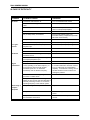
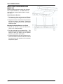
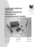
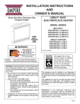
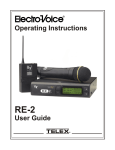
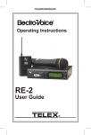
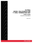
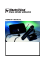
R200 SERIES WIRELESS OWNERS MANUAL R200 OWNERS MANUAL TABLE OF CONTENTS DESCRIPTION .......................................................................................................................................... 3 R200 SERIES COMPONETS ................................................................................................................... 3 QUICK SETUP AND USE ..................................................................................................................... 4-5 COMPATIBILITY ...................................................................................................................................... 6 POTENTIAL SOURCES OF INTERFERENCE ........................................................................................ 6 BATTERY RECOMMENDATIONS ........................................................................................................... 6 SPECIFICATIONS .................................................................................................................................... 7 FCC REGULATIONS ................................................................................................................................ 8 WARRANTY ............................................................................................................................................. 8 IN CASE OF DIFFICULTY ....................................................................................................................... 9 page 2 R200 OWNERS MANUAL R200 SERIES OWNER’S MANUAL System Features True-diversity system with Secure-Phasetm ensures maximum range and freedom from interference Well-designed companding and audio circuitry insure high signal-to-noise ratio and excellent sound quality Description External AC power adapter minimizes noise and makes voltage changes easy if necessary. Power can also be supplied from a 12-volt battery or filtered power supply. Permanently attached, specially-tuned antennas are easy to position RCU: UHF receiver specially designed to reproduce all the nuances of the voice Choice of handheld, bodypack, lavalier, headset and guitar systems GRU: UHF guitar receiver specially designed to handle the transients of a guitar Permanently attached antennas make setup quick and easy. Receivers may be rackmounted with optional kit. The R200 Series receivers are easy to set up and operate. The only controls are the adjustable output level and squelch controls. The antennas are permanently attached telescoping types that are easy to position and are tuned to the range of operation. An optional rack-mount kit allows two systems to be mounted in a single rack space. Audio output via 3-pin XLR-type balanced mic level and ¼-inch unbalanced line level connectors Designed and manufactured in the United States of America DESCRIPTION The Electro-Voice R200 is a series of UHF wireless systems that combine EVs legendary quality, reliability and high value. The R200 Series transmitters and receivers operate in the UHF frequency range between 710.100 and 721.350 MHz (channels 54-55 in the TV band) on single frequencies. The well-designed audio circuitry ensures excellent signal-to-noise ratio with accurate sound quality. SECURE-PHASEtm DIVERSITY The R200 Series receivers utilize patented Secure-Phasetm diversity circuitry that provides the strongest, cleanest signal possible. Unlike other diversity circuits that switch antennas, SecurePhasetm utilizes the signal from both antennas at all times to increase signal strength, minimize dropouts and lower the potential for interference. If the signal from the transmitter changes phase or polarity (a common cause of dropouts), the circuit adjusts the phase angle between the two antennas receiving circuits to prevent cancellation. R200 SERIES COMPONENTS R200 Secure-Phasetm Diversity UHF Receivers Secure-Phasetm diversity for maximum range and reliability Clean, undistorted sound reproduction using proprietary compander circuitry Audio output via rear-mounted XLR-type 3-pin mic level or front-mounted, adjustable line level ¼-inch connector May be rack mounted with optional kit HTU Handheld Transmitter Electro-Voice BK-1 (HTUC) cardioid condenser microphone transducer or Electro-Voice N/ D157 (HTUD) cardioid N/DYM dynamic transducer. Separate LEDs for power on and battery status for easy monitoring of operational modes. Separate power and audio mute switches for operational flexibility. Wide-range gain control allows approximately 40 dB of adjustment. Special soft-touch finish and ergonomically designed handle makes holding comfortable and secure. Up to 10 hours of operation on a 9-volt alkaline battery. Bodypack Transmitters Two models are available: BPU: UHF bodypack with TA4F connector allows the user the freedom of microphone selection. Standard microphones include the Electro-Voice ULM20 cardioid condenser lavalier microphone and the HM2 headset microphone. The TA4F connector allows connection of any dynamic or condenser microphone that can be biased with 5 volts dc phantom. BGU: UHF guitar bodypack with hardwired cable and ¼-inch connector with specially designed audio circuitry to handle guitar transients Separate on/off and large mute switches for operational flexibility LED battery condition indicator gives quick indication of battery strength page 3 R200 OWNERS MANUAL Up to 10 hours of operation on a 9-volt alkaline battery QUICK SETUP AND USE nector is the preferred choice since the output is balanced. Either connector may be used with good results. To get your system into operation quickly, use the following instructions. Review the rest of the manual for additional setup and operational details. 5. Turn the output level control (see Figure 2) on the front panel to the 12:00 oclock position (midway in the controls range) if the ¼-inch connector is used (the 3-pin XLR-type connector has fixed level). 1. Place the receiver where there is a clear line of sight to the area where the transmitter will be used (Figure 1). Extend the receivers antennas and separate them 90 degrees (see Figure 2). 6. Setup and adjust the transmitter level as described on the following pages. 7. Turn up the level on the mixer or preamp to the desired setting. 2. Make sure the sound systems volume is low or off on the input you intend to use for the wireless. 3. Plug in the receivers power adapter into an AC outlet and the other end into the receiver. CAUTION: Please make sure that the AC adapter is the correct voltage for your local requirements. 4. Plug the audio cable (not supplied) into either output connector. The 3-pin XLR-type con- 8. Speak into the microphone or strum the instrument and, if necessary, adjust the receivers output until the volume level from the wireless system approximates the level of an equivalent wired microphone or instrument. 9. Walk the expected area of use to check for dropouts or interference. If problems occur, see the troubleshooting section. Figure 1 SET ANTENNAS AT 90 D EG R EES A U D IO O U T P U T JA C K VOLUM E LEVEL CONTROL POWER L IG H T C A R R IE R (T R A N S M IT T E R O N ) L IG H T HTU HANDHELD TRANSMITTER SETUP 1. Insert battery. Slide open the battery compartment cover by placing your thumb on the indents of the battery door (at the back end of the transmitter) and gently pull down (see Figure 3). 2. Turn on the transmitter by sliding the power switch (closest to the battery compartment) forward to its on position, toward the mic element. The red battery condition light should flash once and then go out. If the red LED stays on or illuminates during a performance, it should be replaced immediately. The green LED will stay lit when the transmitter is on. 3. Check reception. Observe that the audio carrier light on the front panel of the receiver is illuminated, an indication that the receiver is picking up the signal. Then, walk the intended area of use and make sure that there are no barriers to reception or sources of interference. page 4 4. Unmute the audio by sliding the audio switch (immediately below the mic element) towards the windscreen. 5. Adjust the gain if necessary. First, speak or sing into the microphone and listen closely for distortion or hiss. If the gain is too low or high, adjustments are necessary. Gently insert the provided screwdriver (or other 3/32-in. screwdriver) into the hole near the head of the transmitter (see Figure 4). Turn lightly until the screwdriver tip drops into the slot in the level control. Gently turn counterclockwise until the control stops (the mic output is attenuated but not off). Slowly turn the miclevel control while listening to the audio. If the audio becomes distorted, turn the mic level control counter-clockwise about 1/8 turn. 6. Adjust the squelch control if necessary. The squelch control on the back of the receiver may be adjusted to increase range or reduce interference. Turn the control counter- R200 OWNERS MANUAL transmitter off. Turn the squelch control counter-clockwise until you hear noise or interference. Then, turn the squelch clockwise until the noise is gone. clockwise to increase range. Caution! Increasing the range will make the system more susceptible to outside interference! If the squelch is being adjusted, turn the Figure 2 BODYPACK TRANSMITTER SETUP 1. Insert battery. Open the hinged battery compartment by placing your thumb or finger on the indent on the battery door and pull down. When inserting the battery, pay attention to the polarity (+/-) and insert the terminals into the battery compartment first. Close the battery door by sliding the door shut. 2. Turn on the transmitter by sliding the power switch to its on position. Check the condition of the battery by looking at the LED below the power switch. The red battery light should flash once and then go out. If the LED stays on, the battery is weak and should be replaced. 3. Prepare the audio source by attaching the lavalier microphone to the user, placing the headset on the users head or plugging the cable into the instrument (depending on what type of system you have). Keep the audio muted while plugging in and adjusting the microphone or source. Placement of lavalier and headset microphones will noticeably change the sound quality, so some experimentation with the user is necessary. B E LT CL IP M AY B E TU R NE D 90 D E G RE E S BY RE M O V ING S C R E W A N D R EIN STA LLIN G HERE. 4. Check reception by observing that the RF carrier light is illuminated on the receivers front panel. 5. Turn on the audio transmission by sliding the large mute switch to the on position. 6. Listen carefully to the audio and be sensitive of overload distortion and low gain or hiss. 7. Adjust the gain if necessary. Gently insert the provided screwdriver or other 3/32-in. (2.5 mm) screwdriver into the gain adjustment located at the top edge of the battery compartment under the door. The door has to be opened but not swung upward to make adjustments. Turn lightly until the screwdriver tip drops into the slot on the level control. Gently turn the control counterclockwise until the control stops (the audio output is attenuated but not off). Slowly turn the audio level control clockwise while listening to audio; if the audio becomes distorted, turn the mic level control counter-clockwise about 1/8 turn. 8. Clip the bodypack to the users belt or to a pocket. The bodypack can be positioned horizontally or vertically by moving the belt clip attachment. Removing the belt clip attachment screw and moving it 90 degrees will change the orientation. G AIN A DJU S TM E NT DOOR OPENED B UT N O T S W U N G UP WA RD POW ER S W ITC H AU D IO S W ITC H AUD IO P OW ER S W IN G D O O R U P WA R D TO A CC ES S B ATTE RY C O M PA R TM EN T TO O P E N BATTE RY D O O R P R E S S A R RO W W ITH IN D E X FIN G E R AN D P UL L D O W N W ITH TH U M B A N D M IDD LE FIN G E R M IC O R G UITA R CA B LE E NTRY ON ON BATTE RY LIG HT page 5 R200 OWNERS MANUAL COMPATIBILITY The receiver and transmitter must be on the same UHF frequency to operate together. Because of the specialized equipment required to adjust these units properly, users cannot change the frequencies or make any internal adjustments. If two or more R200 and/or other VHF/UHF wireless systems are being used in the same location, proper frequency coordination is necessary to avoid interference. Frequency mixing and spacing must be factored along with local TV stations to determine if conflicts will result from a specific group. Contact your dealer or Electro-Voice for frequency-selection assistance if you are planning to add more wireless systems to be operated simultaneously in the same location. POTENTIAL SOURCES OF INTERFERENCE There are many potential sources of interference for your wireless system. Any electronic compo- page 6 nent that contains digital circuitry including digital signal processors (reverb/multi-effects units), electronic keyboards, digital lighting controllers, CD players and computers all emit rf energy that can affect the performance of your wireless system. It is always best to place your receiver as far away from these devices as possible to minimize this potential source of problems. BATTERY RECOMMENDATIONS Fresh 9-volt alkaline batteries from a quality manufacturer will yield the best performance from R200 transmitters. 8.4-volt ni-cad batteries can be used but will yield much shorter operational time. When the transmitter switch is turned on, the battery light will flash one time if the battery is good. If the light does not flash or stays lit continuously, the battery is weak or dead. If the light comes on during use, the battery is weakening and should be replaced as soon as possible. R200 OWNERS MANUAL R200 SYSTEM SPECIFICATIONS SPECIFICATIONS RCU and GRU Receivers Receiver Type Single-frequency, single-conversion superheterodyne FM Frequency Range (RF) 710.100 721.350 MHz Available Frequencies: 710.100; 714.200; 714.700; 715.100; 716.200; 719.700; 720.350; 721.350 MHz Diversity True Diversity with Secure-Phasetm RF Sensitivity < .8 uV for 12 dB SINAD FCC Data Approved under part 15 Audio Output, Frequency Response 20 15 kHz + 2 dB Audio Output Level 0.775V RMS @ 100 K ohm load Distortion Less than 0.5% Signal-to-Noise Ratio >94 dB Dynamic Range 94 dB UHF Transmitters HTUC, HTUD, BPU, BGU RF Frequency Range 710.100 721.350 MHz Radiated RF Output 35-45 mW typical, 50 mW maximum Microphone Element (HTUC handheld) Electro-Voice BK-1 cardioid condenser Microphone Element (HTUD handheld) Electro-Voice N/D157 cardioid N/DYM Standard Bodypack Microphones Lavalier: Electro-Voice ULM20 cardioid condenser Headset: Electro-Voice HM2 cardioid condenser TA4F Connector Wiring: Pin 1: Ground; Pin 2: Mic Input; Pin 3: +5 volt bias; Pin 4: +5 volt bias fed through a 3 K ohm resistor for 2-wire electrets Audio Gain Adjustment Range 40 dB Battery Life 8 10 hours with 9-Volt alkaline Bodypack Antenna Utilizes microphone cable Size (Handheld transmitter) 27.3 cm (10.75 in) long Size (Bodypack transmitter) HxWxD 4.5 in x 2.6 in x 1.25 in (no antenna) 114.3 x 66.04 x 31.75 mm Accessories: OLM10 450563 300059000 ULM20 Omni lavalier mic w/windscreen and clip Windscreen for OLM10 Clip for OLM10 Unidirectional lavalier mic, windscreen and clip 879155 ULM20 windscreen 879156 ULM20 clip HM2 Unidirectional headset condenser mic 450124 Spring-adjusted mic stand adapter RMR Rack-mount kit for two receivers Optional Accessories: RMR Rack-mount kit PSRUS 120-volt power supply (730123-1) PSRER 230-volt power supply 240-volt power supply PSRBR page 7 R200 OWNERS MANUAL FCC REGULATIONS The Electro-Voice Models HTUC, HTUD, BGU and BPU Transmitters are Type Accepted under United States Federal Communications Commission Part 74H. The Electro-Voice Models RCU and GRU Receivers are accepted under the Part 15 Notification Procedure of the Federal Communications Commission. Licensing of Electro-Voice equipment is the users responsibility and license ability depends on upon the users classification, and frequency selected. Electro-Voice urges the user to contact the appropriate telecommunications authority before ordering frequencies other than factory preset frequencies. CAUTION: Changes or modifications made by the user could void the users authority to operate the equipment. Factory Service If factory service is required, ship the unit prepaid in its original carton to: EVI Audio Service 600 Cecil Street Buchanan, MI 49107 Tel: 616/695-6831 Fax: 616-695-1304 Telex Communications 8601 E. Cornhusker Highway Lincoln, NE 68506 Tel: 402/467-5321 Fax: 402/467-3279 Enclose a note describing the problem along with any other pertinent information. WARRANTY (Limited) Electro-Voice products are guaranteed against malfunction due to defects in materials or workmanship for a specified period, as noted in the individual product-line statement(s) below, or in the individual product data sheet or owners manual, beginning with the date of original purchase. If such malfunction occurs during the specified period, the product will be repaired or replaced (at our option) without charge. The product will be returned to the customer prepaid. Exclusions and Limitations: The Limited Warranty does not apply to: (a) exterior finish or appearance; (b) certain specific described in the individual product-line statement(s) below, or in the individual product data sheet or owners manual; (c) malfunction resulting from use or operation of the product other than as specified in the product data sheet or owners manual; (d) malfunction resulting from misuse or abuse of the product; or (e) malfunction occurring at any time after repairs have been made to the product by anyone other than Electro-Voice or any of its authorized service representatives. Obtaining Warranty Service: To obtain warranty service, the customer must deliver the product, prepaid, to Electro-Voice or any page 8 of its authorized service representatives together with proof of purchase of the product in the form of a bill of sale or receipted invoice. A list of authorized service representatives is available from Electro-Voice at 600 Cecil Street, Buchanan, MI 49107 (616/695-6831 or 800/234-6831). Incidental and Consequential Damages Excluded: Product repair or replacement and return to the customer are the only remedies provided to the customer. Electro-Voice shall not be liable for any incidental or consequential damages including, without limitation, injury to persons or property or loss of use. Some states do not allow the exclusion or limitation of incidental or consequential damages so the above limitation or exclusion may not apply to you. Other Rights: This warranty gives you specific legal rights and you may also have other rights which vary from state to state. Electro-Voice Wireless Systems are guaranteed against malfunction due to defects in materials or workmanship for a period of one (1) year from the date of original purchase. The Limited Warranty does not extend to cables or cable connectors. Additional details are included in the Uniform Limited Warranty Statement. Service and repair addresses for this product:: Telex Communications 8601 East Cornhusker Highway Lincoln, Nebraska 68506 (402/467-5321) and Electro-Voice 600 Cecil Street Buchanan, Michigan 49107 (616/695-6831 or 800-234-6831). R200 OWNERS MANUAL IN CASE OF DIFFICULTY Problem Possible Causes Solutions No audio Transmitter audio switch is off. Turn on transmitter audio switch. Disconnected or damaged receiver audio cable Connect, repair, or replace cable. Transmitter power switch is off. Turn transmitter power switch on, with level down on mixer/preamp/amplifier. Receiver is off. Turn on receiver. No (or dead) battery in transmitter. Insert a freah alkaline battery into transmitter battery compartment (Duracell MN 1604 recommended). Faulty battery contacts in transmitter. Clean contacts. Gain down on mixer/preamp/amplifier. Increase mixer/preamp/amplifier gain. Gain not sufficiently on mixer/preamp/ amplifier input. Increase mixer/preamp/amplifier gain. Receiver audio too low. Increase receiver audio. Low gain/ volume Distortion Signal interference Short-range or frequent drop-outs Transmitter audio level too low. Turn up transmitter audio level. Transmitter audio level too ligh, overloading transmitter circuit. Turn down transmitter audio level. Receiver audio set too high, overloading the mixer/preamp/amplifier input. Turn down receiver audio level. Battery level low in transmitters. Insert fresh battery. Another wireless microphone in the immediate vicinity operating on the same frequency, or on a frequency that mixes with another transmitter (such as a TV broadcast transmitter) onto the wireless frequency. If interference is weak, keep transmitter on to override interference whenever receiver is on (or "fade audio on mixer/preamp/ amplifier). If interference is strong, turn off all other wireless in area to find the one causing the problem. Placement too close to a digital signal processor or similar device. Move receiver to another location. Strong electromagnetic field from stage lighting or other source near the transmitter or receiver, producing "rf noise" on or near the operating frequency of the wireless system. Repair or remove source of interference. Faulty receiving antenna system. Reposition antennas or receiver. Faulty transmitter antenna. Return to factory or authorized service station. Many rf-reflective metal obstacles between the transmitter and receiver. Move the obstacles or reposition the receiver. page 9 R200 OWNERS MANUAL INSTALATION FOR RECEIVER RACK MOUNT KIT R-Series wireless receivers can be rack mounted with the optional RMR kit. The RMR allows two receivers to be mounted side-by-side in a single rack space. Attach Bracket to Receiver 1. Fold antennas down and insert the R-Series receiver through the rectangular cut-out as shown. 2. Align the two holes in the bottom of each receiver with the two holes in the bracket. Secure the receiver to the bracket with the 2 #6 Plastite screws provided. Mounting the Bracket/Receiver on a Rack 1. Secure the bracket to the rack with the 4, 10-32 x 3/8'' screws provided. 2. Fold the antennas up and extend fully. The antennas should be folded 45 from vertical and should not touch the antenna on the adjacent receiver, or any other metal object. 3. Follow the Equipment Set-up procedures as outlined in the R-Series receiver instruction manual for proper set-up and operation of your wireless microphone system. page 10 R200 OWNERS MANUAL page 11 R200 OWNERS MANUAL 600 Cecil Street, Buchanan, MI 49107 800/234-6831, 616/695-6831, 616/695-1304 Fax MANUAL - R200 Series Wireless page 12 ©Telex Communications, Inc. 1998 • Litho in U.S.A. Part Number 535428 — 9902