1
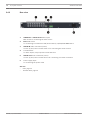
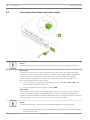
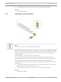
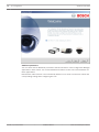
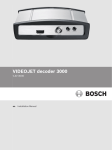
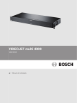
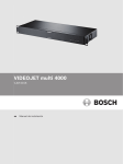
VIDEOJET multi 4000
VJM-4016
en
Installation Manual
VIDEOJET multi 4000
Table of Contents | en
3
Table of contents
1
Safety
5
1.1
Electric shock hazard
5
1.2
Installation and operation
5
1.3
Maintenance and repair
6
2
Short information
7
2.1
About this manual
7
2.2
Conventions in this manual
7
2.3
Intended use
7
2.4
EU Directives
7
2.5
Rating plate
7
3
System overview
8
3.1
Parts included
8
3.2
System requirements
8
3.3
Overview of functions
3.4
Connections, controls and displays
11
3.4.1
Front view
11
3.4.2
Rear view
12
4
Installation
13
4.1
Preparations
13
4.2
Installing in a switch cabinet
13
5
Connection
15
5.1
Connecting cameras
15
5.2
Establishing the network connection
16
5.3
Connecting audio
17
5.4
Connecting alarm inputs and relay output
18
5.5
Creating a serial connection
19
5.6
Power on/power off
20
6
Configuration
21
6.1
Setup
21
6.2
Setup using Video Client
21
7
Troubleshooting
23
7.1
Contact
23
7.2
General malfunctions
23
7.3
Malfunctions with iSCSI connections
24
7.4
LEDs
24
7.5
Processor load
25
7.6
Network connection
25
7.7
Terminal block
25
7.8
Copyrights
26
8
Maintenance
27
8.1
Updates
27
8.2
Factory reset
27
8.3
Repairs
27
9
Decommissioning
28
9.1
Transfer
28
9.2
Disposal
28
Bosch Sicherheitssysteme GmbH
8
Installation Manual
2014.02 | V1 | F.01U.298.750
4
en | Table of Contents
VIDEOJET multi 4000
10
Technical data
29
10.1
Electrical
29
10.2
Mechanical
29
10.3
Environmental conditions
29
10.4
Standards
29
2014.02 | V1 | F.01U.298.750
Installation Manual
Bosch Sicherheitssysteme GmbH
VIDEOJET multi 4000
Safety | en
1
Safety
1.1
Electric shock hazard
–
5
Never attempt to connect the unit to any power network other than the type for which it
is intended.
–
Connect the unit to an earthed mains socket-outlet.
–
Never open the housing.
–
If a fault occurs, disconnect the unit from the power supply and from all other units.
–
Install the unit only in a dry, weather-protected location.
–
When installing in a switch cabinet, ensure that the unit has sufficient grounding.
–
If safe operation of the unit cannot be ensured, remove it from service and secure it to
prevent unauthorized operation. In such cases, have the unit checked by Bosch Security
Systems.
Safe operation is no longer possible in the following cases:
–
if there is visible damage to the unit or power cables,
–
if the unit no longer operates correctly,
–
if the unit has been exposed to rain or moisture,
–
if foreign bodies have penetrated the unit,
–
after long storage under adverse conditions, or
–
after exposure to extreme stress in transit.
Viktige sikkerhetsinstruksjoner (Norway only)
Utstyr som er koplet til beskyttelsesjord via nettplugg og/eller via annet jordtilkoplet utstyr –
og er tilkoplet et kabel-TV nett, kan forårsake brannfare. For å unngå dette skal det ved
tilkopling av utstyret til kabel-TV nettet installeres en galvanisk isolator mellom utstyret og
kabel-TV nettet.
Viktiga säkerhetsinstruktioner (Sweden only)
Utrustning som är kopplad till skyddsjord via jordat vägguttag och/eller via annan utrustning
och samtidigt är kopplad till kabel-TV nät kan i vissa fall medfőra risk főr brand. Főr att undvika
detta skall vid anslutning av utrustningen till kabel-TVnät galvanisk isolator finnas mellan
utrustningen och kabel-TV nätet.
1.2
Installation and operation
–
The relevant electrical engineering regulations and guidelines must be complied with at
all times during installation.
–
Relevant knowledge of network technology is required to install the unit.
–
Before installing or operating the unit, make sure you have read and understood the
documentation for the other equipment connected to it, such as cameras. The
documentation contains important safety instructions and information about permitted
uses.
–
Perform only the installation and operation steps described in this manual. Any other
actions may lead to personal injury, damage to property or damage to the equipment.
Please ensure the following installation conditions:
–
Do not install the unit close to heaters or other heat sources. Avoid locations exposed to
direct sunlight.
–
Allow sufficient space for running cables.
–
Ensure that the unit has adequate ventilation. Bear the total heat output in mind,
particularly when installing multiple units in a switch cabinet.
Bosch Sicherheitssysteme GmbH
Installation Manual
2014.02 | V1 | F.01U.298.750
6
en | Safety
VIDEOJET multi 4000
–
When making connections, use only the cables supplied or use appropriate cables
immune to electromagnetic interference.
–
Position and run all cables so that they are protected from damage, and provide adequate
cable strain relief where needed.
–
When installing in a switch cabinet, ensure that the screw joints are free of tension and
subject to as little mechanical stress as possible. Ensure that the unit has sufficient
grounding.
1.3
Maintenance and repair
–
Never open the housing of the unit. The unit does not contain any user-serviceable parts.
–
Ensure that all maintenance or repair work is carried out only by qualified personnel
(electrical engineers or network technology specialists). In case of doubt, contact your
dealer's technical service center.
2014.02 | V1 | F.01U.298.750
Installation Manual
Bosch Sicherheitssysteme GmbH
VIDEOJET multi 4000
Short information | en
2
Short information
2.1
About this manual
7
This manual is intended for persons responsible for the installation and operation of the
VIDEOJET multi 4000 encoder. International, national and any regional electrical engineering
regulations must be followed at all times. Relevant knowledge of network technology is
required. The manual describes the installation of the unit.
Conventions in this manual
2.2
In this manual, the following symbols and notations are used to draw attention to special
situations:
Warning!
!
Use of this signal word and symbol indicates that failure to follow the safety instructions
described may endanger persons. It indicates a hazardous situation which, if not avoided,
could result in death or serious injury.
Caution!
!
Use of this signal word and symbol indicates that failure to follow the safety instructions
described may endanger persons. It indicates a hazardous situation which, if not avoided,
could result in minor or moderate injury.
Notice!
Use of this signal word and symbol indicates that failure to follow the safety instructions
described may cause damage to the unit or other equipment or may lead to data loss.
2.3
Intended use
The VIDEOJET multi 4000 encoder transfers video, audio, and control signals over data
networks (Ethernet LAN, Internet). The unit is intended for use with CCTV systems. Various
functions can be triggered automatically by incorporating external alarm sensors. Other
applications are not permitted.
In the event of questions concerning the use of the unit which are not answered in this
manual, please contact your sales partner or:
Bosch Sicherheitssysteme GmbH
Robert-Bosch-Ring 5
85630 Grasbrunn
Germany
www.boschsecurity.com
2.4
EU Directives
The VIDEOJET multi 4000 encoder complies with the requirements of EU Directives 89/336
(Electromagnetic Compatibility) and 73/23, amended by 93/68 (Low Voltage Directive).
2.5
Rating plate
For exact identification, the model name and serial number are inscribed on the bottom of the
housing. Please make a note of this information before installation, if necessary, so as to have
it to hand in case of questions or when ordering spare parts.
Bosch Sicherheitssysteme GmbH
Installation Manual
2014.02 | V1 | F.01U.298.750
8
en | System overview
VIDEOJET multi 4000
3
System overview
3.1
Parts included
–
1 VIDEOJET multi 4000 video encoder
–
1 accessory bag
–
1 Installation Manual
–
optional: 1 power cord (depending on the ordered product package)
Notice!
Check that the delivery is complete and in perfect condition. Arrange for the unit to be
checked by Bosch Security Systems if you find any damage.
3.2
System requirements
General requirements
–
Computer with Windows XP or Windows 7 operating system
–
Network access (Intranet or Internet)
–
Screen resolution at least 1,024 × 768 pixels
–
16- or 32-bit color depth
–
Installed Oracle JVM
Note:
The Web browser must be configured to enable cookies to be set from the IP address of the
unit.
In Windows 7, deactivate protected mode on the Security tab under Internet Options.
You can find notes on using Microsoft Internet Explorer in the online Help in Internet Explorer.
Additional configuration and operational requirements
You find the information on additional configuration and operational requirements in the
Releaseletter document for the respective firmware.
For the latest version of the firmware, required programs and controls, and the current version
of the Video Client management software, access your Bosch product catalog on the Internet.
3.3
Overview of functions
Network video server
The VIDEOJET multi 4000 encoder is a compact network video server for 16 connected video
sources. It is primarily designed for encoding video, audio and control data for transfer over an
IP network. With its encoding in the H.264 format, the unit is ideally suited for making existing
analog CCTV cameras IP-compatible and for remote access to digital VCRs and multiplexers.
The use of existing networks means that integration with CCTV systems or local networks can
be achieved quickly and easily.
Video images from a single sender can be received simultaneously on multiple receivers. Audio
signals can also be transmitted from and to compatible units.
Dual Streaming
The encoder uses the feature Dual Streaming to generate two independent IP video streams
per channel, both at full 4CIF resolution and with full frame rate.
Video encoding
The VIDEOJET multi 4000 High Profile encoder uses the H.264 video compression standard.
Thanks to efficient encoding, the data rate remains low even with high image quality and can
also be adapted to local conditions within wide limits.
2014.02 | V1 | F.01U.298.750
Installation Manual
Bosch Sicherheitssysteme GmbH
System overview | en
VIDEOJET multi 4000
9
Audio encoding
The VIDEOJET multi 4000 encoder uses the G.711, AAC, and L16 audio compression
standards. G.711 is the default setting for live transmission. For recording the default setting
is AAC. When configuring with a Web browser, you can select your preferred standard for
recording. Using video management systems, this is also true for live audio.
Viewing
View the encoder video on a PC using a Web browser, in Bosch Video Management System, or
integrate it into another video management system. By routing the IP video to a highperformance VIDEOJET decoder or to Monitor Wall, you can present the video with ultimate
clarity.
Recording
You can record each video input independently on different media. Thus video can be
recorded centrally on iSCSI drives managed by VRM.
The encoder features a highly flexible recording scheduler, providing up to ten programmable
recording profiles and allowing individually assigned camera profiles. With these profiles, you
can accelerate the frame rate as well as increase the quality on alarm, saving recording space
during non-alarm periods.
Multicast
In suitably configured networks, the multicast function enables simultaneous real-time video
transmission to multiple receivers. The UDP and IGMP V2 protocols must be implemented on
the network for this function.
Access security
The encoder offers various security levels for accessing the network, the unit, and the data
channels. As well as password protection with up to three levels, they support 802.1x
authentication using a RADIUS server for identification. You can secure Web browser access
by HTTPS using an SSL certificate that is stored in the unit. For total data protection, each
communication channel—video, audio, or serial I/O—can be independently AES encrypted.
Remote control
For remote control of external units such as pan or tilt heads for cameras or motorized zoom
lenses, control data is transmitted via the encoder's bidirectional serial interface. This
interface can also be used to transmit transparent data.
Intelligence
The encoder comes with built-in MOTION+ video motion detection. This motion detection
algorithm is based on pixel change and includes object size filtering capabilities.
On alarm, the device can send an e‑mail with JPEG images attached.
ONVIF conformance
Conformance to ONVIF 1.02 and ONVIF Profile S provides interoperability between network
video products regardless of manufacturer. In addition, the firmware of the device supports all
applicable features of the ONVIF 2.2 specification.
ONVIF conformant devices are able to exchange live video, audio, metadata, and control
information and ensure that they are automatically discovered and connected to network
applications such as video management systems.
Bosch Sicherheitssysteme GmbH
Installation Manual
2014.02 | V1 | F.01U.298.750
10
en | System overview
VIDEOJET multi 4000
Summary
The VIDEOJET multi 4000 encoder provides the following main functions:
–
Video, audio, and data transmission over IP data networks
–
Dual Streaming function for the encoder for simultaneous encoding with two individually
–
Multicast function for simultaneous image transmission to multiple receivers
–
16 analog BNC composite video inputs (PAL/NTSC)
–
Video encoding according to international standard H.264
–
Deinterlacing at video input and progressive encoding
–
Integrated Ethernet port (10/100/1000 Base-T)
–
Network-attached iSCSI recording
–
Transparent, bidirectional data channel via RS-232/RS-422/RS-485 serial interface
–
Configuration and remote control of all internal functions via TCP/IP, also secured via
definable profiles
HTTPS
–
Password protection to prevent unauthorized connection or configuration changes
–
4 alarm inputs for external sensors (such as door contacts)
–
1 relay output for switching external units (such as lamps or sirens)
–
Built-in video sensor for motion alarms
–
Event-controlled automatic connection
–
Convenient maintenance via uploads
–
Flexible encryption of control and data channels
–
Authentication according to international standard 802.1x
–
Bidirectional audio (mono) for line connections
–
Audio encoding according to international standards AAC, G.711, and L16
2014.02 | V1 | F.01U.298.750
Installation Manual
Bosch Sicherheitssysteme GmbH
VIDEOJET multi 4000
System overview | en
3.4
Connections, controls and displays
3.4.1
Front view
1
11
Factory reset button
to restore factory default settings
2
LED ACTIVITY
flashes during data transmission
3
LED LINK
lights up when the unit is connected to the network
4
LED STATUS
lights up during startup
5
LED CONNECT
lights up when supplied with power after startup
See also
–
LEDs, page 24
Bosch Sicherheitssysteme GmbH
Installation Manual
2014.02 | V1 | F.01U.298.750
12
en | System overview
3.4.2
VIDEOJET multi 4000
Rear view
1
VIDEO IN 1 to VIDEO IN 16 video inputs
BNC socket for connecting the video source
2
ETH RJ45 socket
for connecting to an Ethernet LAN (local network), 10/100/1000 MBit Base-T
3
AUDIO IN audio connection (mono)
3.5 mm (1/8 in) stereo socket audio in for connecting two audio sources
4
Terminal block
for alarm inputs, relay output and serial interface
5
AUDIO OUT audio connection (mono)
3.5 mm (1/8 in) stereo socket line-out for connecting one audio connection
6
Power supply input
for connecting the power cable
See also
–
LEDs, page 24
–
Terminal block, page 25
2014.02 | V1 | F.01U.298.750
Installation Manual
Bosch Sicherheitssysteme GmbH
VIDEOJET multi 4000
Installation | en
4
Installation
4.1
Preparations
13
The VIDEOJET multi 4000 encoder is designed for installation in a switch cabinet. Mounting
the unit in a 19-inch rack using the installation material supplied is a quick and easy operation.
Please ensure the following installation conditions:
–
Do not install the unit close to heaters or other heat sources. Avoid locations exposed to
direct sunlight.
–
Allow sufficient space for running cables.
–
Ensure that the unit has adequate ventilation. Bear the total heat output in mind,
particularly when installing multiple units in a switch cabinet.
–
When making connections, use only the cables supplied or use appropriate cables
immune to electromagnetic interference.
–
Position and run all cables so that they are protected from damage, and provide adequate
cable strain relief where needed.
4.2
Installing in a switch cabinet
Notice!
When installing in a switch cabinet, ensure that there is sufficient ventilation for the unit.
There must be at least 5 cm (1.97 in) of free space to the left and right of the unit and at least
10 cm (3.94 in) at the rear.
The unit generates heat during operation. During installation, please note the maximum heat
value of 79 BTU/h.
When mounting additional units, direct contact with the encoder is permitted, provided that
the surface temperature of the adjacent units does not exceed +50 °C (+122 °F).
When installing in a switch cabinet, ensure that the screw joints are free of tension and
subject to as little mechanical stress as possible. Ensure that the unit has sufficient grounding.
1.
Prepare the switch cabinet in such a manner that you are easily able to insert the unit
directly at the installation point.
2.
Place the cage nuts in the corresponding drillings or spaces in the switch cabinet frame.
3.
Lift the unit into the switch cabinet frame and insert the fastening screws together with
the washers.
4.
Tighten the screws one after the other and then check once more that all the screws are
tight.
Bosch Sicherheitssysteme GmbH
Installation Manual
2014.02 | V1 | F.01U.298.750
14
en | Installation
2014.02 | V1 | F.01U.298.750
VIDEOJET multi 4000
Installation Manual
Bosch Sicherheitssysteme GmbH
VIDEOJET multi 4000
Connection | en
5
Connection
5.1
Connecting cameras
15
You can connect a maximum of 16 video sources to the VIDEOJET multi 4000 encoder. Any
cameras and other video sources that produce a standard PAL or NTSC signal are suitable.
4
Connect each of the cameras or other video sources to BNC sockets VIDEO IN 1 to
VIDEO IN 16 using a video cable (75 ohm, BNC plug).
Note that termination is always on.
Bosch Sicherheitssysteme GmbH
Installation Manual
2014.02 | V1 | F.01U.298.750
16
5.2
en | Connection
VIDEOJET multi 4000
Establishing the network connection
You can connect the unit to a 10/100/1000 Base-T network using a standard UTP category 5
cable with RJ45 plugs.
4
2014.02 | V1 | F.01U.298.750
Connect the unit to the network via the ETH socket.
Installation Manual
Bosch Sicherheitssysteme GmbH
VIDEOJET multi 4000
5.3
Connection | en
17
Connecting audio
The unit has two audio ports for audio line signals.
The audio signals are transmitted two-way and in sync with the video signals. The following
specifications should be complied with in all cases.
2 × audio in:
Impedance 9 kohm typ., 5.5 Vp-p max. input voltage; microphone
amplifier 60 dB max.
1 × line out:
3.0 Vp-p typ. output voltage at 10 kohm impedance
The stereo plug must be connected as follows:
Contact
AUDIO IN
AUDIO OUT
Tip
Channel 1
Channel 1
Middle ring
Channel 2
—
Lower ring
Ground
Ground
1.
Connect an audio source to the AUDIO IN socket with a 3.5 mm (1/8 in) stereo plug.
2.
Connect an audio receiver with line-in connection to the AUDIO OUT socket with a
3.5 mm (1/8 in) stereo plug.
Note that the audio function is not activated by default. To use audio connections activate the
corresponding setting when configuring the unit.
Bosch Sicherheitssysteme GmbH
Installation Manual
2014.02 | V1 | F.01U.298.750
18
5.4
en | Connection
VIDEOJET multi 4000
Connecting alarm inputs and relay output
Notice!
For correct connection of alarm inputs and relay outputs, observe the labelling on the unit.
Alarm inputs
The unit has 4 alarm inputs on the terminal block. The alarm inputs are used to connect to
external alarm devices such as door contacts or sensors. With the appropriate configuration,
an alarm sensor can automatically connect the unit to a remote location, for example.
A zero potential closing contact or switch can be used as the actuator. If possible, use a
bounce-free contact system as the actuator.
1.
Connect the lines to the appropriate terminals on the terminal block (IN1 to IN4) and
check that the connections are secure.
2.
Connect each alarm input to a ground contact (GND).
Relay output
The unit has one relay output for switching external units such as lamps or alarm sirens. You
can operate the relay output manually while there is an active connection to the unit. The
output can also be configured to automatically activate sirens or other alarm units in response
to an alarm signal. The relay output is also located on the terminal block.
Notice!
A maximum load of 30 Vp-p (SELV) and 200 mA may be applied to the relay contacts.
1.
Connect the lines to the appropriate terminals R on the terminal block and check that the
connections are secure.
2014.02 | V1 | F.01U.298.750
Installation Manual
Bosch Sicherheitssysteme GmbH
VIDEOJET multi 4000
Connection | en
2.
19
Connect the terminal block to the socket on the unit observing the labeling.
See also
–
5.5
Terminal block, page 25
Creating a serial connection
Notice!
For correct connection, observe the labelling on the unit.
The bidirectional data interface is used to control units connected to the VIDEOJET multi 4000
encoder, such as a dome camera with a motorized lens. The connection supports the RS-232,
RS-422, and RS-485 transmission standards. A video connection is necessary to transmit
transparent data.
The serial interface is also located on the terminal block.
The range of controllable equipment is expanding constantly. The manufacturers of the
relevant equipment provide specific information on installation and control. Please take note
of the appropriate documentation when installing and operating the peripheral to be
controlled. The documentation contains important safety instructions and information about
permitted uses.
1.
If you require a serial connection to the unit, connect the relevant cables to the terminal
block and check that the connections are secure.
2.
Connect the terminal block to the socket on the unit observing the labeling.
See also
–
Terminal block, page 25
Bosch Sicherheitssysteme GmbH
Installation Manual
2014.02 | V1 | F.01U.298.750
20
5.6
en | Connection
VIDEOJET multi 4000
Power on/power off
Depending on the ordered product package, the unit is delivered together with a power cord.
Notice!
Use only a suitable power cord. Where necessary, use suitable facilities to ensure that the
power supply is free of interference such as voltage surges, spikes or brownouts. Connect the
unit to an earthed mains socket-outlet.
Do not connect the unit to the power supply until all other connections have been made.
1.
Make sure to use a suitable power cord and connect it to the unit.
2.
Plug the power cord into the mains. The unit is ready for use as soon as the CONNECT
LED lights up.
Provided the network connection has been correctly made, the LINK LED also lights up. The
flashing LED ACTIVITY signals traffic on the network.
See also
–
2014.02 | V1 | F.01U.298.750
LEDs, page 24
Installation Manual
Bosch Sicherheitssysteme GmbH
VIDEOJET multi 4000
Configuration | en
6
Configuration
6.1
Setup
21
Before you can operate the unit within your network, it must have a valid IP address for your
network and a compatible subnet mask.
Note:
As a default DHCP is enabled in the unit’s network settings. With an active DHCP server in the
network you must know the IP address assigned by the DHCP server to operate the unit.
The following default address is preset at the factory: 192.168.0.1
The setup procedure is carried out via our Video Client software or other management
systems. All information regarding the configuration can be found in the relevant
documentation of the video management system in use.
6.2
Setup using Video Client
For the current version of our Video Client management software, access your Bosch product
catalog on the Internet. This program allows you to implement and set up the unit in the
network quickly and conveniently.
Installing the program
1. Download Video Client from the Bosch product catalog on the Internet.
2.
Unzip the file.
3.
Double-click the installer file.
4.
Follow the instructions on the screen to complete the installation.
Configuring the unit
You can start Video Client immediately after installation.
1.
Double-click the
icon on the desktop to start the program. Alternatively, start the
application via the Start button and the Programs menu (path: Start/Programs/
Bosch Video Client/Bosch Video Client).
2.
When the program is started for the first time, a wizard opens to help you detect and
configure devices on the network.
3.
If the wizard does not start automatically, click
to open the Configuration Manager
application. Then, click Configuration Wizard... on the Tools menu.
4.
Follow the instructions given in the Configuration Wizard window.
Bosch Sicherheitssysteme GmbH
Installation Manual
2014.02 | V1 | F.01U.298.750
22
en | Configuration
VIDEOJET multi 4000
Additional parameters
You can check and set additional parameters with the assistance of the Configuration Manager
application in Video Client. You can find detailed information on this in the documentation for
these applications.
Note that the audio function is not activated by default. To use audio connections activate the
corresponding setting when configuring the unit.
2014.02 | V1 | F.01U.298.750
Installation Manual
Bosch Sicherheitssysteme GmbH
VIDEOJET multi 4000
Troubleshooting | en
7
Troubleshooting
7.1
Contact
23
If you are unable to resolve a malfunction, please contact your supplier or systems integrator,
or go directly to Bosch Security Systems Customer Service.
The following tables are intended to help you identify the causes of malfunctions and correct
them where possible.
7.2
General malfunctions
Malfunction
Possible causes
Recommended solution
No image transmission
Camera error.
Connect local monitor to the
to remote station.
camera and check the camera
function.
Faulty cable connections.
Check all cables, plugs,
contacts and connections.
PAL camera connected after
Reboot the unit.
booting.
No connection
The unit's configuration.
established, no image
transmission.
Check all configuration
parameters.
Faulty installation.
Check all cables, plugs,
contacts and connections.
Wrong IP address.
Check the IP addresses.
Faulty data transmission within
Check the data transmission
the LAN.
with e.g. ping.
The maximum number of
Wait until there is a free
connections has been reached.
connection and then call the
unit again.
No audio transmission to Hardware fault.
Check that all connected audio
remote station.
units are operating correctly.
Faulty cable connections.
Check all cables, plugs,
contacts and connections.
Incorrect configuration.
Check audio parameters.
The audio connection is already Wait until the connection is
in use by another receiver.
free and then call the unit
again.
The unit does not report
an alarm.
Alarm source is not selected.
Check alarm source settings.
No alarm response specified.
Specify the desired alarm
response, change the IP
address, if necessary.
Bosch Sicherheitssysteme GmbH
Installation Manual
2014.02 | V1 | F.01U.298.750
24
en | Troubleshooting
VIDEOJET multi 4000
Malfunction
Possible causes
Recommended solution
Control of cameras or
The cable connection between
Check all cable connections
other units is not
the serial interface and the
and ensure all plugs are
possible.
connected unit is not correct.
properly fitted.
The interface parameters do
Make sure that the settings of
not match those of the other
all units involved are
unit connected.
compatible.
The unit is not
Power failure during
Have the unit checked by
operational after a
programming by firmware file.
Customer Service and replace
firmware upload.
it, if necessary.
Incorrect firmware file.
Enter the IP address of the unit
followed by /main.htm in your
Web browser and repeat the
upload.
Placeholder with a red
JVM not installed on your
Install Oracle JVM from the
cross instead of the
computer or not activated.
Bosch product catalog on the
ActiveX components.
Web browser contains
Internet.
Active proxy server in network.
empty fields.
Create a rule in the local
computer's proxy settings to
exclude local IP addresses.
7.3
Malfunctions with iSCSI connections
Malfunction
Possible causes
Recommended solution
After connecting to the
Incorrect LUN mapping during
Check the iSCSI system
iSCSI target, no LUNs
iSCSI system configuration.
configuration and reconnect.
After connecting to the
The LUN list could not be read,
Check the iSCSI system
iSCSI target, "LUN FAIL"
as it was assigned to the wrong configuration and reconnect.
appears below a node.
network interface.
LUN mapping is not
Some iSCSI systems do not
possible.
support the use of an initiator
are displayed.
Delete the initiator extension.
extension.
7.4
LEDs
The unit has LEDs on its front and rear panels that show the operating status and can give
indications of possible malfunctions:
ACTIVITY LED
Flashes:
Traffic on the network.
LINK LED
Lights up:
2014.02 | V1 | F.01U.298.750
Network connection established.
Installation Manual
Bosch Sicherheitssysteme GmbH
VIDEOJET multi 4000
Troubleshooting | en
25
STATUS LED
Lights up:
Startup in progress.
Flashes:
The unit is faulty, for example following failed firmware
upload.
CONNECT LED
Lights up:
The unit is switched on and startup completed.
Flashes:
Video connection active.
RJ45 socket LEDs
Left LED flashes (as ACTIVITY
Traffic on the network.
LED):
Right LED lights up (as LINK
Network connection established.
LED):
7.5
Processor load
If the unit is accessed via the Web browser, you will see the processor load indicator bar in
the top right of the window next to the information icon
.
You can obtain additional information to help you when troubleshooting or fine tuning the
unit. The values indicate the proportions of the individual functions on the coder load, shown
as percentages.
Move the cursor over the graphic indicator. Some additional numerical values are also
4
displayed.
7.6
Network connection
You can display information about the network connection. To do this, move the cursor over
.
7.7
Link
Ethernet link type
UL
Uplink, speed of the outgoing data traffic
DL
Downlink, speed of the incoming data traffic
Terminal block
The terminal block has several contacts for:
–
Serial data transmission
–
4 alarm inputs
–
1 relay output
Pin assignment serial interface
Options for using the serial interface include transferring transparent data, controlling
connected units or operating the unit with a terminal program.
Bosch Sicherheitssysteme GmbH
Installation Manual
2014.02 | V1 | F.01U.298.750
26
en | Troubleshooting
VIDEOJET multi 4000
The serial interface supports the RS-232, RS-422 and RS-485 transmission standards. The
mode used depends on the current configuration.
The pin assignment of the serial interface depends on the interface mode used:
Contact
RS-232 mode
RS-422 mode
RS-485 mode
CTS
—
RxD- (receive data minus)
—
TXD
TxD (transmit data)
TxD- (transmit data minus)
Data-
RTS
—
TxD+ (transmit data plus)
Data+
RXD
RxD (receive data)
RxD+ (receive data plus)
—
GND
GND (ground)
—
—
Pin assignment I/O
Contact
Function
IN1
Input alarm 1
IN2
Input alarm 2
IN3
Input alarm 3
IN4
Input alarm 4
GND
Ground
R
Relay output
Connect each alarm input to a ground contact (GND).
7.8
Copyrights
Fonts
The firmware uses the fonts "Adobe-Helvetica-Bold-R-Normal--24-240-75-75-P-138-ISO10646-1"
and "Adobe-Helvetica-Bold-R-Normal--12-120-75-75-P-70-ISO10646-1" under the following
copyright:
Copyright 1984-1989, 1994 Adobe Systems Incorporated.
Copyright 1988, 1994 Digital Equipment Corporation.
Permission to use, copy, modify, distribute and sell this software and its documentation for
any purpose and without fee is hereby granted, provided that the above copyright notices
appear in all copies and that both those copyright notices and this permission notice appear
in supporting documentation, and that the names of Adobe Systems and Digital Equipment
Corporation not be used in advertising or publicity pertaining to distribution of the software
without specific, written prior permission.
Software
This software is based in part on the work of the Independent JPEG Group.
Audio
AAC audio technology licensed by Fraunhofer IIS (http://www.iis.fraunhofer.de/amm/).
2014.02 | V1 | F.01U.298.750
Installation Manual
Bosch Sicherheitssysteme GmbH
VIDEOJET multi 4000
Maintenance | en
8
Maintenance
8.1
Updates
27
Firmware updates are carried out via our Video Client software or other management systems
in use. Please refer to the relevant documentation.
8.2
Factory reset
You can use the factory reset button to restore the unit to its original settings. Any changes to
the settings are overwritten by the factory defaults. A reset may be necessary, for example, if
the unit has invalid settings that prevent it from functioning as desired.
1.
Using a pointed object, press the factory reset button located on the front panel until the
STATUS LED flashes. All settings will revert to their defaults.
2.
The unit is ready for configuration as soon as the CONNECT LED lights up.
See also
–
8.3
Configuration, page 21
Repairs
–
Never open the housing of the unit. The unit does not contain any user-serviceable parts.
–
Ensure that all maintenance or repair work is carried out only by qualified personnel
(electrical engineers or network technology specialists). In case of doubt, contact your
dealer's technical service center.
Bosch Sicherheitssysteme GmbH
Installation Manual
2014.02 | V1 | F.01U.298.750
28
en | Decommissioning
VIDEOJET multi 4000
9
Decommissioning
9.1
Transfer
VIDEOJET multi 4000 should only be passed on together with this installation manual.
9.2
Disposal
Your Bosch product is designed and manufactured with high-quality materials and
components which can be recycled and reused.
This symbol means that electrical and electronic equipment, at their end-of-life, should be
disposed of separately from your household waste.
In the European Union, there are separate collection systems for used electrical and electronic
products. Please dispose of this equipment at your local community waste collection/recycling
center.
2014.02 | V1 | F.01U.298.750
Installation Manual
Bosch Sicherheitssysteme GmbH
VIDEOJET multi 4000
Technical data | en
10
Technical data
10.1
Electrical
10.2
Input voltage
100 to 240 V AC, 47 to 63 Hz
Input current
0.32 to 0.15 A
Power consumption
23 W max
Connectors
IEC 320 C14
29
Mechanical
Dimensions (H × W ×D)
44 × 443 × 157 mm (1.732 × 17.441 × 6.181 in),
without brackets including BNC sockets
Weight
Approx. 1.7 kg (3.7 lb)
Video
16 × BNC socket, 75 ohm, terminated
Analog composite, 0.7 to 1.2 Vp-p, NTSC or PAL
Audio
2 × 3.5 mm (1/8 in) stereo socket (2 × mono in, microphone/line;
1 × mono line out)
Signal line in
9 kohm typical, 5.5 Vp-p max, microphone amplifier 60 dB max
Signal line out
3.0 Vp-p at 10 kohm typical
Ethernet
10/100/1000 Base-T, auto-sensing,
half/full duplex, RJ45
COM port
1 × RS-232/RS-422/RS-485, bidirectional, push-in terminal
Alarm
4 × push-in terminal input (non-isolated closing contact),
activation resistance 10 ohm max
Relay
1 × push-in terminal output
30 Vp-p (SELV), 200 mA
Display
4 × LED (ACTIVITY, LINK, STATUS, CONNECT) on the front panel
2 × LED (data transfer, network connection) on the rear panel
10.3
10.4
Environmental conditions
Operating temperature
0 °C to +50 °C (+32 °F to +122 °F)
Storage temperature
0 °C to +50 °C (+32 °F to +122 °F)
Relative humidity
0 to 95% atmospheric humidity, non-condensing
Thermal value
79 BTU/h max
Standards
Video standards
PAL, NTSC
Video coding protocols
H.264 High Profile (ISO/IEC 14496-10)
M-JPEG
Video data rates
9.6 kbps to 2 Mbps per channel
Connections
Min. 16 simultaneous unicast/multicast
Image resolutions
4CIF
704 × 576/480 (PAL/NTSC)
GOP structure
Bosch Sicherheitssysteme GmbH
I, IP
Installation Manual
2014.02 | V1 | F.01U.298.750
30
en | Technical data
VIDEOJET multi 4000
Total delay
260 ms typical
Dual Streaming
Full performance and full frame rate on both streams for every
video input channel
Frame rate
1 to 25/30 ips (PAL/NTSC)
Audio standards
G.711, L16, AAC-LC
Audio frequency rate
G.711: 300 Hz to 3.4 kHz
L16: 300 Hz to 6.4 kHz
AAC-LC: 300 Hz to 6.4 kHz
Audio sampling rate
G.711: 8 kHz
L16: 16 kHz
AAC-LC: 16 kHz
Audio data rate
G.711: 80 kbps
L16: 640 kbps
AAC-LC: 48 kbps
Signal-to-noise ratio
> 50 dB
Network protocols
IPv4, IPv6, UDP, TCP, HTTP, HTTPS, RTP/RTCP, IGMP V2/V3,
ICMP, ICMPv6, RTSP, FTP, Telnet, ARP, DHCP, SNTP, 802.1x,
DNS, DNSv6, DDNS (DynDNS.org, selfHOST.de, no-ip.com),
SMTP, iSCSI, UPnP (SSDP), DiffServ (QoS), LLDP, SOAP,
Dropbox, CHAP, digest authentication
Encryption
2014.02 | V1 | F.01U.298.750
TLS 1.0, SSL, DES, 3DES, AES
Installation Manual
Bosch Sicherheitssysteme GmbH
VIDEOJET multi 4000
Index | en
31
Index
A
N
Alarm, 12
Network, 16
Alarm input, 18
Network connection, 12, 20, 25
Audio connections, 12, 17
O
C
Operation, 5
Cameras, 15
Overview of functions, 8
Closing contact, 18
P
Conventions, 7
D
Parameters, 22
Pin assignment, 26
Danger, 5
Processor load, 25
Data interface, 19
Processor load indicator, 25
Default
IP address, 21
Default IP address, 21
DHCP, 21
Dome camera, 19
Dual Streaming, 8
E
R
Rear panel connections, 12
Regulations, 7
Relay, 12, 18
Relay outputs, 18
Remote control, 9
Repair, 6, 27
Electromagnetic compatibility, 7
Reset, 11, 27
Encoding, 8
S
H
Safety, 5
Heat value, 13
Screen resolution, 8
I
Serial interface, 12
Identification, 7
Installation, 5
Installation conditions, 5, 13
Serial number, 7
Signal source, 18
Symbols, 7
Installation equipment, 13
T
Installing in a switch cabinet, 13
Transmission standards, 19, 26
Interface, 26
Trigger, 18
IP address
U
Default, 21
L
Low Voltage Directive, 7
M
Unit reset, 27
V
Ventilation, 13
Main functions, 10
Maintenance, 6, 27
Multicast function, 9
Bosch Sicherheitssysteme GmbH
Installation Manual
2014.02 | V1 | F.01U.298.750
Bosch Sicherheitssysteme GmbH
Robert-Bosch-Ring 5
85630 Grasbrunn
Germany
www.boschsecurity.com
© Bosch Sicherheitssysteme GmbH, 2014