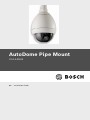
1
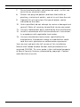
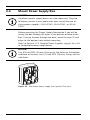
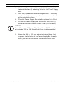
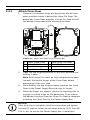
AutoDome Pipe Mount
VG4-A-9543
en
Installation Guide
AutoDome Pipe Mount
Table of Contents | en
3
Table of Contents
1
Important safety instructions
5
2
Installing the Pipe Mount
7
2.1
Unpacking
7
2.1.1
Parts List
7
2.1.2
Optional Mounting Accessories
7
2.1.3
Optional Power Supplies
8
2.1.4
Description
8
2.1.5
Tools Required
8
2.2
Pre-installation Check List
9
2.3
Pressurized Environmental Mounting Option
11
2.4
Mount Power Supply Box
12
2.4.1
Attach Cover Door
14
2.5
Route Wires and Attach Connectors
15
2.5.1
Methods for Routing Wires
16
2.5.2
Wiring the Power Supply Box
18
2.5.3
Power Supply Box Connections
19
2.6
Installing the VG4-A-9543 Pipe Mount
21
2.7
Wire the Pipe Interface Board
23
2.7.1
Wiring for Multiple AutoDomes
25
2.7.2
Connecting Wires to the Pipe Interface Board
25
2.8
Attach Pendant to Pipe and Tighten
29
3
Cable and Wire Standards
31
3.1
Power
31
3.2
Wire Distance Guide
31
3.3
Video and Control Cables
32
3.3.1
Using Coaxial Cable to Transmit Video and Control
32
3.3.2
Using UTP to Transmit Video and Control
33
3.3.3
Using Ethernet to Transmit Video and Control
34
3.3.4
Using Multi-mode Fiber Optic to Transmit Video and Control
34
3.3.5
Using a Fiber Optic Ethernet Media Converter to Transmit Video
and Control
35
3.4
Control-only Cables
35
3.4.1
Controlling the AutoDome via Biphase
35
Bosch Security Systems, Inc.
Installation Guide
F.01U.251.410 | 1.0 | 2011.08
4
en | Table of Contents
AutoDome Pipe Mount
3.4.2
Controlling the AutoDome via the RS232 Protocol
37
3.4.3
Controlling the AutoDome via the RS485 Protocol
39
3.5
Fiber Optic Module with an RS232/RS422 Controller
41
3.5.1
Connecting to an LTC 4629 Head End Data/Video Transceiver 41
3.5.2
Configuring the VG5 AutoDome
41
3.6
Audio Cables
43
4
Alarms and Relay Connections
45
4.1
Alarm Inputs
45
4.2
Configuring Supervised Alarms (inputs 1 and 2)
45
4.2.1
Configuring a Normally Open Supervised Alarm
46
4.2.2
Configuring a Normally Closed Supervised Alarm
46
4.3
Configuring Non-supervised Alarms (inputs 1 through 7)
47
4.3.1
Configuring a Normally Open Non-supervised Alarm
47
4.3.2
Configuring a Normally Closed Non-supervised Alarm
48
4.4
Alarm Outputs
48
4.4.1
Configuring a Dry Contact Relay
48
4.4.2
Configuring an Open Collector Output
49
F.01U.251.410 | 1.0 | 2011.08
Installation Guide
Bosch Security Systems, Inc.
AutoDome Pipe Mount
1
Important safety instructions | en
5
Important safety instructions
Type numbers:
DANGER!
High risk: This symbol indicates an imminently hazardous
situation such as “Dangerous Voltage” inside the product.
If not avoided, this will result in an electrical shock, serious
bodily injury, or death.
WARNING!
Medium risk: Indicates a potentially hazardous situation.
If not avoided, this could result in minor or moderate bodily
injury.
CAUTION!
Low risk: Indicates a potentially hazardous situation.
if not avoided, this could result in property damage or risk of
damage to the unit.
Read, follow, and retain all of the following safety instructions.
Heed all warnings on the unit and in the operating instructions
before operation.
1.
Clean only with a dry cloth. Do not use liquid cleaners or
aerosol cleaners.
2.
Do not install unit near any heat sources such as radiators,
heaters, stoves, or other equipment (including amplifiers)
that produce heat.
3.
Do not block any ventilation openings.
4.
Do not use the unit near water or expose to rain or
moisture. Never spill liquid of any kind on the unit.
5.
Unplug the unit during lightning storms or when unused for
long periods. Take precautions to protect the unit from
power and lightning surges.
6.
Adjust only those controls specified in the operating
instructions.
Bosch Security Systems, Inc.
Installation Guide
F.01U.251.410 | 1.0 | 2011.08
6
en | Important safety instructions
AutoDome Pipe Mount
7.
Do not overload outlets and extension cords, as this can
8.
Protect the plug and power cord from foot traffic or
9.
Operate the unit only from the type of power source
cause fire or electrical shock.
pinching, at electrical outlets, and at its exit from the unit.
indicated on the label.
10. Unless qualified, do not attempt to service a damaged unit
yourself. Refer all servicing to qualified service personnel.
11. Use only replacement parts specified by the manufacturer.
12. Install in accordance with the manufacturer's instructions
in accordance with applicable local codes.
13. Use only attachments/accessories specified by the
manufacturer. Equipment change or modification could
void the user's guarantee or authorization agreement.
You can view and print the full version of this Installation
Manual with Adobe Acrobat Reader, both provided on the
enclosed CD-ROM. This user guide is the intellectual property
of Bosch Security Systems; protected by copyright. Contact:
www.boschsecurity.com
F.01U.251.410 | 1.0 | 2011.08
Installation Guide
Bosch Security Systems, Inc.
AutoDome Pipe Mount
Installing the Pipe Mount | en
2
Installing the Pipe Mount
2.1
Unpacking
7
This equipment should be unpacked and handled with care. If
an item appears to have been damaged in shipment, notify the
shipper immediately.
Verify that all the parts listed in the product's Parts List below
are included. If any items are missing, notify your Bosch
Security Systems Sales or Customer Service Representative.
The original packing carton is the safest container in which to
transport the unit and must be used if returning the unit for
service. Save it for possible future use.
2.1.1
Parts List
The following table lists the parts included with this mounting
package.
Part Numbers
Pipe Mount
2.1.2
VG4-A-9543
Optional Mounting Accessories
The following table lists the optional parts you may need for
attaching a pendant to a pipe mount.
Mounting Options
Part Numbers
Pipe Mount for Pressurized
VG4-A-9543N
Environmental Housing
Roof Parapet Mount
VGA-ROOF-MOUNT
Flat Roof Mount Adapter
LTC 9230/01
Bosch Security Systems, Inc.
Installation Guide
F.01U.251.410 | 1.0 | 2011.08
8
en | Installing the Pipe Mount
2.1.3
AutoDome Pipe Mount
Optional Power Supplies
The pipe mount does not come with an attached power supply.
The following table lists the optional power supplies that are
compatible with VG5 Series AutoDomes:
Mounting Options
Part Numbers
24 VAC (no transformer), NEMA-rated with
VG4-A-PSU0
cover
2.1.4
120 VAC transformer, NEMA-rated with cover
VG4-A-PSU1
230 VAC transformer, NEMA-rated with cover
VG4-A-PSU2
Description
This chapter details how to install an AutoDome pipe mount.
Any variations to the installation procedures are noted.
Note: You may need to purchase additional mounting
accessories for roof mount applications. Refer to
Section 2.1.2 Optional Mounting Accessories, page 7.
2.1.5
Tools Required
–
–
5 mm Allen wrench (supplied)
Small straight blade screwdrivers ~ 2.5 mm (0.1 in.) – 3.1
mm (1/8 in.)
–
Medium straight blade screwdriver
–
No. 1 and No. 2 Phillips screwdrivers
–
Socket wrench and 9/16 in. socket
–
Pipe Wrench
F.01U.251.410 | 1.0 | 2011.08
Installation Guide
Bosch Security Systems, Inc.
AutoDome Pipe Mount
2.2
Installing the Pipe Mount | en
9
Pre-installation Check List
1.
Determine the location and distance for the power supply
box based on its voltage and current consumption. Refer
to Section 3 Cable and Wire Standards, page 31 for wiring
information and distances.
2.
Use only UL listed liquid tight strain reliefs for conduits to
the Power Supply Box to ensure that water cannot enter
the box. You must use water tight conduits and fittings to
meet NEMA 4 standards.
NOTICE!
Power and I/O cabling must be routed separately inside
different permanently earthed metal conduits.
3.
Install all rough wiring including: power, control, video
coax, alarms I/O, relay I/O, and fiber optic cabling. Refer to
Section 3 Cable and Wire Standards, page 31 for video and
control protocol methods.
4.
Analog AutoDome: If you plan to use the RS232 or RS485
protocol to control the AutoDome, refer to
Section 3.4.2 Controlling the AutoDome via the RS232
Protocol, page 37, or Section 3.4.3 Controlling the
AutoDome via the RS485 Protocol, page 39, for instructions
on configuring the AutoDome to accept these protocols.
WARNING!
External interconnecting cables are to be installed in
accordance to NEC, ANSI/NFPA70 (for US application) and
Canadian Electrical Code, Part I, CSA C22.1 (for CAN
application) and in accordance to local country codes for all
other countries.
Branch circuit protection incorporating a 20 A, 2-pole Listed
Circuit Breaker or Branch Rated Fuses are required as part of
the building installation. A readily accessible 2-pole disconnect
device with a contact separation of at least 3 mm must be
incorporated.
Bosch Security Systems, Inc.
Installation Guide
F.01U.251.410 | 1.0 | 2011.08
10
en | Installing the Pipe Mount
AutoDome Pipe Mount
5.
Choose the appropriate VG5 AutoDome model (indoor or
6.
Purchase the appropriate mounting hardware to use,
outdoor) for the environment in which it will be used.
depending on the location of the AutoDome and the
application.
CAUTION!
Select a rigid mounting location to prevent excessive vibration
to the AutoDome camera.
F.01U.251.410 | 1.0 | 2011.08
Installation Guide
Bosch Security Systems, Inc.
AutoDome Pipe Mount
2.3
Installing the Pipe Mount | en
11
Pressurized Environmental Mounting
Option
The AutoDome Pressurized Environmental Housing must be
mounted to the appropriate pipe mount. The mounts for the
Pressurized Environmental Housing have been modified to
remove the guide pins that serve as installation aids. You must
mount the Pressurized Environmental Housing to the VG4-A9543N Pipe Mount.
CAUTION!
DO NOT mount a Pressurized Environmental Housing to the
VG4-A-9543 mounting option. This pipe mount contains guide
pins that are not compatible with the Pressurized
Environmental Housing. Refer to item 1 on the image below:
If your pipe mount contains these pins, DO NOT attempt to
mount a Pressurized Environmental Housing to this mount. You
must order the VG4-A-9543N pipe mount option for the
Pressurized Environmental Housing.
Bosch Security Systems, Inc.
Installation Guide
F.01U.251.410 | 1.0 | 2011.08
12
en | Installing the Pipe Mount
2.4
AutoDome Pipe Mount
Mount Power Supply Box
NOTICE!
AutoDome power supply boxes are sold separately. Skip the
following section if your application does not utilize one of
these power supplies: VG4-A-PSU0, VG4-A-PSU1, or VG4-APSU2.
Before mounting the Power Supply Box decide if you will be
wiring the box through the holes in the bottom or back of the
box. If wiring the box through the back, move the two (2) seal
plugs to the bottom holes before mounting.
Refer to Section 2.1.3 Optional Power Supplies, page 8, for a list
of compatible power supply boxes.
NOTICE!
Use 3/4-inch NPS (20-mm) fittings for the holes on the bottom
and back of the box. Use 1/2-inch NPS (15-mm) fittings for the
side holes.
Figure 2.1
F.01U.251.410 | 1.0 | 2011.08
Wall Mount Power Supply with Optional Trim Skirt
Installation Guide
Bosch Security Systems, Inc.
AutoDome Pipe Mount
1.
Installing the Pipe Mount | en
13
Use the wall mount template supplied in the packaging box
to locate the four (4) mounting holes for the Power Supply
Box.
2.
Drill four (4) holes for the mounting anchors. If installing
outdoors, apply a weatherproof sealant around each hole
at the mounting surface.
3.
Place the Power Supply Box into the optional Trim Skirt.
4.
Secure the Power Supply Box to the wall using four (4)
corrosion-resistant stainless steel studs (not included).
NOTICE!
A stud diameter of 6.4 mm (1/4 in.) or 8 mm (5/16 in.), able to
withstand a 120 kg (265 lb) pull-out force is recommended.
5.
Attach the 3/4 in. (20 mm) watertight pipe fittings (not
supplied) to the holes of the Power Supply Box through
which you will run the power, video, and control data
wires.
Bosch Security Systems, Inc.
Installation Guide
F.01U.251.410 | 1.0 | 2011.08
14
en | Installing the Pipe Mount
2.4.1
AutoDome Pipe Mount
Attach Cover Door
1.
Compress the bottom hinge pin by pushing the pin lever
down and then rotate it behind the Hinge Pin Stop. The
power box Cover Door provides a Hinge Pin Stop to hold
the bottom hinge open while attaching the door.
(FUSE)
o
(FUSE)
HTR
(FUSE)
DOME
90
24V
NC 24V
GND TXD RXD Figure 2.2
1
2
3
4
2.
C+ C-
GND TXD RXD C+ C-
Align Cover Door Hinge to Power Box
Power Supply Box 5
Cover Door
6
Align Top Hinge
7
Align Bottom Hinge
Hold Hinge Pin Open
Open Position
Hinge Pin Stop
Open the top hinge by pushing its pin lever outward and
holding it open.
Note: Both Hinge Pins must be fully compressed to open
(unlock) the female hinges of the Cover Door before
proceeding to the next step.
3.
While holding the top hinge pin open, position the Cover
Door to the Power Supply Box and align its hinges.
4.
When the hinges are aligned, release the top hinge pin to
engage its mating hinge on the power box. Then release
the bottom hinge pin from the Hinge Pin Stop to complete
attaching the Cover Door to the Power Supply Box.
NOTICE!
After all wiring is complete, close the cover door and tighten
the two (2) captive screws on the cover door to 10-12 N-m (90105 in.-lbs) to ensure the Power Supply Box is watertight.
F.01U.251.410 | 1.0 | 2011.08
Installation Guide
Bosch Security Systems, Inc.
AutoDome Pipe Mount
2.5
Installing the Pipe Mount | en
15
Route Wires and Attach Connectors
NOTICE!
AutoDome power supply boxes are sold separately. Skip the
following section if your application does not utilize one of
these power supplies: VG4-A-PSU0, VG4-A-PSU1, or VG4-APSU2.
Power wires must be routed to the left (front) side of the
Power Supply Box through a separate conduit. All video,
control, and alarm wires must be routed through a second
conduit to the right side of the box. Refer to Section 3 Cable and
Wire Standards, page 31 for methods of transmitting video and
data, and for wire specifications.
WARNING!
External interconnecting cables are to be installed in
accordance to NEC, ANSI/NFPA70 (for US application) and
Canadian Electrical Code, Part I, CSA C22.1 (for CAN
application) and in accordance to local country codes for all
other countries.
Branch circuit protection incorporating a 20 A, 2-pole Listed
Circuit Breaker or Branch Rated Fuses are required as part of
the building installation. A readily accessible 2-pole disconnect
device with a contact separation of at least 3 mm must be
incorporated.
Bosch Security Systems, Inc.
Installation Guide
F.01U.251.410 | 1.0 | 2011.08
16
en | Installing the Pipe Mount
2.5.1
AutoDome Pipe Mount
Methods for Routing Wires
There are two possible methods to route the video, control, and
alarm wires:
–
One is to route the video, control, and alarm wires through
the conduit fitting on the right (front) side of the Power
XF103
DOME
54321
HTR
P107
XF101
(FUSE)
J103
(LED)
NC 24V
P106
GND TXD RXD Figure 2.3
P105
C+ C-
GND TXD RXD XF102
P101
24V
(FUSE)
J101
J102
(FUSE)
Supply Box and out to the AutoDome Interface Board.
C+ C-
VG4-A-PSU1 or VG4-A-PSU2 Power Supply Box
1 120 VAC/230 VAC
Power In
5 Coax, UTP Video, or Ethernet
Wire
(Ethernet for VG5 700 Series only)
2 P101 Connector
6 Control Wire
3 Ground Connection 7 24 VAC Power Out
4 Transformer
8 P107 Connector
F.01U.251.410 | 1.0 | 2011.08
Installation Guide
Bosch Security Systems, Inc.
AutoDome Pipe Mount
–
Installing the Pipe Mount | en
17
The second method is to bypass the Power Supply Box and
route the video, control, and alarm wires directly to the
Interface Board. You connect only the power wires inside
the Power Supply Box.
GND TXD RXD P105
C+ C-
GND TXD RXD P104
P101
P102
P107
P106
XF102
J103
(LED)
24V
AGND
A7
A6
A5
A4
A3
P103
XF103
DOME
P107
HTR
54321
XF101
(FUSE)
P101
24V NC
AGND
OUT 3
OUT 2
OUT 1
(FUSE)
J101
J102
(FUSE)
J102
P105
BNC
C+ C-
J101
P106
Figure 2.4 VG4-A-PSU1 or VG4-A-PSU2 Power Supply Box Connected to Pipe Interface Board
1
2
3
4
5
6
VG4-A-PSU1/VG4-A-PSU2
120 VAC/230 VAC Power In
P101 Connector
Ground Connection
Transformer
24 VAC Power Out
P107 Connector
7
8
9
10
11
12
13
14
15
Pipe Interface Board
P101 Connector
P107 Connector
24 VAC Power In (to AutoDome)
Earth Ground
24 VAC Power In (to AutoDome)
24 VAC Power In (to Heater)
24 VAC Power In (to Heater)
AutoDome Power
Heater Power
NOTICE!
Fiber Optic Models require that the Biphase control wires be
routed from the Power Supply Box P106 connector out to the
Pipe Interface Board P105 connector.
Bosch Security Systems, Inc.
Installation Guide
F.01U.251.410 | 1.0 | 2011.08
18
en | Installing the Pipe Mount
2.5.2
AutoDome Pipe Mount
Wiring the Power Supply Box
1.
Route the high voltage 115/230 VAC lines through the
conduit fitting on the left side of the box.
NOTICE!
The Power Supply Box with transformer comes with a barrier
that separates the high voltage side on the left from the low
voltage 24 VAC side on the right.
2.
Cut and trim the high voltage 115/230 VAC power and
ground wires with sufficient slack to reach their connector
terminal in the box, but not so long as to be pinched by or
to obstruct closing the Cover Door.
3.
Attach the supplied 3-pin Power Plug to the incoming high
voltage power wires in the box. Refer to connector P101 in
Table 2.1, Page 20.
4.
Analog AutoDome: If you are using UTP for video, route
the UTP cable out to where the AutoDome will be
mounted. Refer to Section 3 Cable and Wire Standards,
page 31 for fiber optic specifications.
5.
IP AutoDome: Route the Ethernet cable out to where the
AutoDome will be mounted. Refer to Section 3 Cable and
Wire Standards, page 31 for specifications.
6.
Route the low power 24 VAC wires from the right side of
the Power Supply Box out to where the AutoDome will be
mounted. Attach the supplied 5-pin 24 VAC Dome plug to
the wire ends inside the box. Refer to connector P107 in
Table 2.1, Page 20.
NOTICE!
All video, control, and alarm wires either pass through the
Power Supply Box or by-pass it and connect directly to the Pipe
Interface Board.
F.01U.251.410 | 1.0 | 2011.08
Installation Guide
Bosch Security Systems, Inc.
AutoDome Pipe Mount
2.5.3
Installing the Pipe Mount | en
19
Power Supply Box Connections
The following figure is a detailed illustration of the Roof or Pipe
Mount Power Supply Box, which includes the fuse
XF102
(LED)
GND T XD RXD
C+
C-
6 5 4 3 2 1
CONTROL
TO DOM
ME
P105
GND T XD RXD
C+
J103
J103
123
CONTROL
IN/OUT
P106
(FUSE))
DOME
HTR
P107
XF101
(FUSE))
P101
24V NC 24V
(FUSE))
J101
1
J102
5 4 3 2 1 XF103
specifications.
C-
6 5 4 3 2 1
1
2
Ground Screw
Transformer (115/
5
6
Power In
In/Out; 1/2 in. (15 mm) NPS
3
230 VAC Modes)
In/Out to Dome
7
Fitting
Power In; 3/4 in. (20 mm) NPS
4
24 VAC to Dome
8
Fitting
Control Data and Video In/Out;
Interface Board
3/4 in. (20 mm) NPS Fitting
WARNING!
Fuse replacement by qualified service personnel only. Replace
with same type fuse.
Bosch Security Systems, Inc.
Installation Guide
F.01U.251.410 | 1.0 | 2011.08
20
en | Installing the Pipe Mount
AutoDome Pipe Mount
Fuse Specifications
Volts
XF101 Mains
XF102 Camera
XF103 Heater
24 V
T 5.0 A
T 2.0 A
T 3.15 A
115 V
T 1.6 A
T 2.0 A
T 3.15 A
230 V
T 0.8A
T 2.0 A
T 3.15 A
The following table lists the Power Supply Box connectors:
No.
Connector
Pin 1
Ground
Grounding Screw
P101 115/230 VAC or
Line
Pin 2
NC
Pin 3
Pin 4
Pin 5
Pin 6
Neutral
24 VAC Power In
Earth
RXD (+)
TXD (-)
Signal
C+
P105 Control to Dome C(Fiber Optic
1
(Biphase) (Biphase Ground (RS-232/485) (RS-232/485) Ground
Model)
)
P106 Control In/Out
1
(Optional)
C-
C+
Earth
RXD (+)
TXD (-)
Signal
(Biphase) (Biphase Ground (RS-232/485) (RS-232/485) Ground
)
P107 24 VAC Power to Dome
Dome Plug
24 VAC
Dome
Earth
24 VAC
Ground (24 VAC)
Heater
Heater
(24 VAC)
1. Applicable to VG5 600 and 100 Series AutoDomes only.
Table 2.1 Power Box Connections
F.01U.251.410 | 1.0 | 2011.08
Installation Guide
Bosch Security Systems, Inc.
AutoDome Pipe Mount
2.6
Installing the Pipe Mount | en
21
Installing the VG4-A-9543 Pipe Mount
This section details the installation steps for the VG4-A-9543
Pipe Mount.
NOTICE!
Customer must supply 1-1/2 inch (NPS) pipe threaded on both
ends with a minimum length of 5 inches (12.7 cm).
5 in.
12.7 cm
Figure 2.5
1
2
3
1.
min.
Pipe Mount
Gasket
Flange
Cap
Before installing the Top-Mounting Flange, ensure there is
an adequate opening in the ceiling or mounting structure
for the wires to pass through.
2.
Secure the pipe Flange with supplied gasket to the ceiling
or other supporting structure using four (4) 10-mm (3/8inch) diameter fasteners.
NOTICE!
Each fastener must have a minimum pullout strength of 275 kg
(600 lbs). The mounting material must be able to withstand this
pull-out force. For example, 19-mm (3/4-inch) minimum for
plywood.
Bosch Security Systems, Inc.
Installation Guide
F.01U.251.410 | 1.0 | 2011.08
22
en | Installing the Pipe Mount
3.
AutoDome Pipe Mount
Attach pipe (not supplied) to the Top-mounting Flange.
WARNING!
You must thread the pipe onto the Top-mounting Flange until it
is tight. Failure to do so can result in damage, serious injury or
death.
4.
Route the power, video, control, and alarm wires through
5.
Wrap at least five layers of Teflon tape around the threads.
the Top-Mounting Flange and down the pipe.
6.
Apply the supplied thread sealant to the threads on the
Pipe.
–
Make sure all surfaces are clean and dry.
–
Apply a bead of sealant completely around the leading
threads of the male fitting.
–
Force the adhesive into the threads to thoroughly fill
all voids.
7.
Thread the Pipe Cap onto the down pipe and tighten
securely to prevent leaks.
WARNING!
You must thread the Dome Cap onto the pipe until it is tight.
Failure to do so can result in damage or serious injury or death.
F.01U.251.410 | 1.0 | 2011.08
Installation Guide
Bosch Security Systems, Inc.
AutoDome Pipe Mount
2.7
Installing the Pipe Mount | en
23
Wire the Pipe Interface Board
This section provides instructions for connecting wires and
cables to the Pipe Interface Board, as illustrated below. Refer
to Section 3 Cable and Wire Standards, page 31 for cable and
wiring recommendations and specifications.
BNC
P105
6
5
4
3
2
J102
1
7
P102
5
4
3
2
1
3
P101
AGND
A7
A6
A5
A4
A3
P103
AGND
OUT 3
OUT 2
OUT 1
P104
6
2
P107
1
2
1
J101
P106
Figure 2.6
Bosch Security Systems, Inc.
Pipe Interface Board Connections
Installation Guide
F.01U.251.410 | 1.0 | 2011.08
24
en | Installing the Pipe Mount
AutoDome Pipe Mount
Ref.
1
2
3
Description
Connector Wire Gauge Pin Description
Pipe Interface Module
Video Coax In
J102
6-pin Connector Alarms P103
4
In (3-7)
4-pin Connector Alarms P102
5
6
Out (1-3)
100 Ω Resistor
Data In/Out
P105
P105
7
Alarms In (EOLR
P104
Supervised, 1-2)
8
Relay Output
P104
9
Dome Power
P101
10
Heater Power
P107
11
RJ45 Ethernet or UTP
J101
AWG 26-16 1
2
3
4
5
6
AWG 26-16 7
6
5
4
AWG 26-16 3
2
1
AWG 18-14 3
2
1
AWG 18-14 2
1
Biphase (C-)
Biphase (C+)
Earth Ground
RxD +
TxD Signal Ground
Ground
Alarm 2
Alarm 1
Earth Ground
Normally Closed
Common
Normally Open
Dome 24 VAC
Earth Ground
Dome 24 VAC
Heater 24 VAC
Heater 24 VAC
Video
(Ethernet for VG5 700
Series only)
12
To AutoDome
F.01U.251.410 | 1.0 | 2011.08
Installation Guide
Bosch Security Systems, Inc.
AutoDome Pipe Mount
2.7.1
Installing the Pipe Mount | en
25
Wiring for Multiple AutoDomes
To wire multiple AutoDomes in a series, or “daisy chaining,” you
must apply a terminating resistor to the last dome of the series.
The Interface Board is supplied with a 100 Ω terminating
resistor located between the Biphase terminals C- and C+ (pins
1 and 2) of the P105 control connector (see item 5 in Figure 2.6
above). Remove the resistor from all but the last AutoDome
Interface Board. The maximum number of AutoDomes that can
be daisy chained is four (4).
If using the RS485 protocol for control, switch the terminating
resistor from the Biphase C+ and C- terminals to the RxD+ and
TxD- terminals (pins 4 and 5) of the P105 control connector for
the last dome (refer to item 6 in Figure 2.6 above).
2.7.2
Connecting Wires to the Pipe Interface Board
The Pipe Interface Board contains all of the connectors for
control, data, image, and power wires. Follow the procedures
below to make the proper connections.
WARNING!
Use a 24 VAC Class 2 power supply only.
1.
Analog AutoDome: Attach a BNC connector to the video
coax cable and connect it to its mating connector J102 on
the Pipe Interface Board.
2.
Analog AutoDome: If using UTP for video, attach an RJ45
connector plug to the UTP cable and connect the plug to
its mating connector J101 on the Pipe Interface Board.
WARNING!
Do not connect the RJ45 connector unless using UTP video.
This connection causes video distortion.
3.
IP AutoDome: Attach an RJ45 connector plug to the
Ethernet cable and connect the plug to its mating
connector J101 on the Pipe Interface Board.
Bosch Security Systems, Inc.
Installation Guide
F.01U.251.410 | 1.0 | 2011.08
26
en | Installing the Pipe Mount
AutoDome Pipe Mount
WARNING!
Do not connect the RJ45 connector unless using UTP video or
Ethernet. This connection causes video distortion.
4.
Attach the control data in/out wires to their respective
terminals on the P105 connector on the Pipe Interface
Board. Refer to Figure 2.6, Page 23, for an illustration of
these connections.
5.
Connect the 24 VAC power wires to the P101 connector on
the Pipe Interface Board. If this model has a heater,
connect the 24 VAC heater power wires to connector
P107.
CAUTION!
To protect the AutoDome from damage due to cold
temperatures, ensure that you connect the 24 VAC heater
power wires to the P101 connector.
6.
To connect alarm inputs and outputs, attach the supplied
6-pin Alarms In and the 4-pin Alarms Out connector plugs
with flying leads to the appropriate alarm wires. Then
connect the plugs to their mating connectors P103 and
P102 on the Pipe Interface Board.
WHITE
2
BROWN
3
ORANGE
4
GREEN
F.01U.251.410 | 1.0 | 2011.08
BROWN
ORANGE
GREEN
P103
A2 GND
Figure 2.7
WHITE
A1
PIN
1
2
3
4
5
6
P102
N.O. COM N.C.
PIN
1
YELLOW
BLUE
P104
Alarm and Relay Connector Plugs
Installation Guide
Bosch Security Systems, Inc.
AutoDome Pipe Mount
1
4-pin Alarm
Installing the Pipe Mount | en
2
6-pin Alarm In
3
27
7-pin Relay Connector
Connector (P102)
Connector (P103)
(P104)
Pin Description
Pin Description
Pin Description
1 Alarm Out 1
1 Alarm In 3
1 Alarm Out 4 Normally
2
3
Alarm Out 2
Alarm Out 3‡
2
3
Alarm In 4
Alarm In 5
2
3
Open
Alarm Out 4 COM
Alarm Out 4 Normally
4
Alarm Ground
4
5
6
Alarm In 6
Alarm In 7
Alarm Ground
4
5
6
7
Closed
Earth Ground
Analog Alarm 1
Analog Alarm 2
Ground
7.
To connect supervised alarms and relays, attach the
appropriate wires to their terminals on the P104 connector
on the Pipe Interface Board (see Figure 2.7, above). In
addition, refer to Section 4 Alarms and Relay Connections,
page 45 for more details on wiring alarms and relays.
Note: There is a slot located at the top of the Interface
Board to tie the wires to the circuit board with a cable tie.
Bosch Security Systems, Inc.
Installation Guide
F.01U.251.410 | 1.0 | 2011.08
28
en | Installing the Pipe Mount
8.
AutoDome Pipe Mount
Insert the Pipe Interface Board into the down pipe and
fasten the three (3) retaining screws to secure the board
to the Dome Cap.
CAUTION!
Be careful not to strip the threads when tightening the Pipe
Interface Board retaining screws.
Figure 2.8
1
2
3
Pipe Interface Board to Dome Cap Assembly
Interface Board
Retaining Screws (3)
Pendant Mounting Screws (2)
F.01U.251.410 | 1.0 | 2011.08
Installation Guide
Bosch Security Systems, Inc.
AutoDome Pipe Mount
2.8
Installing the Pipe Mount | en
29
Attach Pendant to Pipe and Tighten
1.
Before attaching the Pendant, visually inspect the Pendant
dome and the Interface Board connectors for any blocked
pin holes and bent pins.
2.
Tilt the Pendant enough to place its mounting hook on top
of the its housing, over the recessed hinge pin of the Dome
Cap.
a
b
c
Figure 2.9 Pendant to Pipe Mount Attachment
1
2
2a
2b
2c
3
4
Tilt Dome
Hook and drop
Dome Cap
Recessed Hinge Pin
Dome Connector
Rotate down to engage dome connector
Tighten the two (2) mounting screws to a minimum
torque of 10-12 N-m (90-105 in.-lbs)
Bosch Security Systems, Inc.
Installation Guide
F.01U.251.410 | 1.0 | 2011.08
30
en | Installing the Pipe Mount
3.
AutoDome Pipe Mount
Drop the Pendant down slightly to engage the dome hook
and hinge pin of the Dome Cap, allowing the dome to
rotate around the hinge pin.
4.
Rotate the dome housing down to a vertical position and
gently push upward to engage the connector on top of the
dome housing.
CAUTION!
If you feel any resistance when rotating the dome housing or
when engaging the connector, stop immediately and start over.
5.
Hold the housing firmly in position and alternately tighten
the two (2) 5-mm Allen head mounting screws from above
to a torque value of 10-12 N-m (90-105 in.-lbs).
CAUTION!
You must tighten the two mounting screws to a minimum
torque of 10-12 N-m (90-105 in.-lbs) to ensure a proper seal
between the arm and the housing.
6.
Rotate the arm to swing the AutoDome out from the roof
and into position.
7.
Tighten the three (3) 10-mm (3/8-inch) stainless steel hex
bolts on the bracket to lock the Parapet Arm in position.
Refer to Figure 2.9, Page 29, for an illustration.
CAUTION!
Do not over tighten the bolts. The maximum torque is 34 N-m
(25 ft-lb).
F.01U.251.410 | 1.0 | 2011.08
Installation Guide
Bosch Security Systems, Inc.
AutoDome Pipe Mount
3
Cable and Wire Standards | en
31
Cable and Wire Standards
CAUTION!
Installation should only be performed by qualified service
personnel in accordance with the National Electrical Code or
applicable local codes.
CAUTION!
All wires for installation applications must be routed through a
grounded conduit.
3.1
Power
24/115/230 VAC
Copper Wire
3.2
To comply with local codes.
Wire Distance Guide
24 V to AutoDome
AutoDome 100, Indoor
VA /
14 AWG
16 AWG
Watts
(2.5 mm)
(1.5 mm)
18 AWG (1.0 mm)
14 / 7.5
248 m (813 ft)
156 m (512 ft)
98 m (322 ft)
47 / 43.5
74 m (242 ft)
46 m (152 ft)
29 m (96 ft)
27 / 15
129 m (422 ft)
81 m (265 ft)
51 m (167 ft)
55 / 51
63 m (207 ft)
40 m (130 ft)
25 m (82 ft)
AutoDome 700, Indoor
35 / 19
99 m (325 ft)
62 m (205 ft)
39 m (129 ft)
AutoDome 700, Outdoor2
60 / 55
58 m (190 ft)
36 m (119 ft)
23 m (75 ft)
AutoDome 100, Outdoor
AutoDome 600, Indoor
AutoDome 600,
Outdoor1
1. Standard heater module. Add Add 16 W if using VG4-SHTR-XT kit.
2. Standard heater module. The VG4-SHTR-XT kit is not applicable to VG5 700 Series
AutoDomes.
Bosch Security Systems, Inc.
Installation Guide
F.01U.251.410 | 1.0 | 2011.08
32
en | Cable and Wire Standards
AutoDome Pipe Mount
3.3
Video and Control Cables
3.3.1
Using Coaxial Cable to Transmit Video and Control
CAUTION!
600 Series AutoDome: If you are using coaxial cable to transmit
video and data between the AutoDome and the head-end, you
must use the coax cable with ferrite included in the AutoDome
packaging. You must connect the incoming coax cable (from the
^00600
head-end) to the jack (female end) on the ferrite cable and
connect the plug end (male connector) of the ferrite cable to
the AutoDome’s coax connector.
Coaxial cable terminated with BNC connectors is the most
common method for transmitting composite video. Bilinx
control data can also be sent over the same cable.
Bilinx is a Bosch 2-way communication protocol that allows
remote control, configuration, and updates over a video coax
cable. Bilinx is available on all VG5 100 and 600 Series
AutoDomes.
VG5 Series AutoDomes feature cable compensation or “PreComp,” which extends the range of video from the head end.
Cable
Maximum Distances
Compensation
Cable Type
RG-59/U
RG-6/U
RG-11/U
Size
Shield
Central Conductor
Terminal Connector
Video Only
Bilinx Control
Pre-comp OFF
Pre-comp ON
Pre-comp ON or OFF
300 m (1000 ft) 600 m (2000 ft) 300 m (1000 ft)
450 m (1500 ft) 900 m (3000 ft) 450 m (1500 ft)
600 m (2000 ft) 1200 m (4000 ft) 600 m (2000 ft)
O.D. between 4.6 mm (0.181 in.) and 7.9 mm (0.312 in.)
Copper braid: 95%
Standard copper center
BNC
WARNING!
Cable compensation (Pre-Comp) does not extend the range of
Bilinx control. Pre-Comp is not available with VG5 700 Series
AutoDomes.
F.01U.251.410 | 1.0 | 2011.08
Installation Guide
Bosch Security Systems, Inc.
AutoDome Pipe Mount
3.3.2
Cable and Wire Standards | en
33
Using UTP to Transmit Video and Control
Unshielded twisted pair (UTP) cable terminated with RJ45 male
connectors are used to transmit composite video using pins
1(+) and 2(-). Typically, a Coax to UTP cable converter is
required at the head-end of the system.
Bilinx control data can also be sent over the same two video
wires (1 & 2). Bilinx is a Bosch 2-way communication protocol
that allows remote control, configuration and updates over a
passive UTP cable.
VG5 100 and 600 Series AutoDomes feature cable
compensation or “Pre-Comp,” which extends the normal range
of control from the head end.
WARNING!
Do not connect the RJ45 connector unless using UTP video.
Cable Compensation
Cable Type
CAT5 UTP
Terminal Connector
Requirement
Maximum Distance
Pre-comp OFF Pre-comp ON
229 m (750 ft) 450 m (1500 ft)
RJ45
Coax to UTP Converter
The following figure illustrates the connections necessary to
transmit video and control over a UTP cable.
1(+) &
+
-
RJ4
Figure 3.1
1
2
Video and Control over UTP
Head End Video
Coax
Bosch Security Systems, Inc.
3
4
Pins
AutoDome
Installation Guide
F.01U.251.410 | 1.0 | 2011.08
34
en | Cable and Wire Standards
3.3.3
AutoDome Pipe Mount
Using Ethernet to Transmit Video and Control
CAUTION!
Ethernet connections must be made to non-exposed (indoor)
networks only.
The AutoDome VG5 700 series connects to a 10 Base-T/100
Base-TX network either directly or via a switch. Both video and
control are transmitted over a standard TCP/IP network using
the built-in Web server.
Cable Type
Maximum Distance
Bandwidth
Terminal Connector
CAT-5E or CAT 6 Ethernet
100 m (328 ft)
10 Base-T/100 Base-TX
RJ45, Female
WARNING!
Do not connect a coaxial cable while the RJ45 Ethernet cable is
connected.
3.3.4
Using Multi-mode Fiber Optic to Transmit Video
and Control
Fiber Optic kits, available for AutoDome 100 and 600 Series
cameras, transmit both video and Biphase control over an
analog singlemode or multimode fiber.
Multimode
Fiber Type
50/125 µm, 62.5/125 µm, low loss multimode glass
fiber
Maximum Distance
4 km (2.5 miles)
Minimum Bandwidth 20 MHz (Video - 850 nm / Control - 1300 nm)
Requirement
Bosch LTC 4629 Fiber Receiver at controller end of
Terminal Connector
system
ST
Singlemode
Fiber Type
Maximum Distance
Minimum Bandwidth
Requirement
9/125 µm, low loss single glass fiber
69 km (43 miles)
20 MHz (Video - 1310 nm /Control - 1550 nm)
Single mode fiber receiver at controller end of
Terminal Connector
system
ST
F.01U.251.410 | 1.0 | 2011.08
Installation Guide
Bosch Security Systems, Inc.
AutoDome Pipe Mount
3.3.5
Cable and Wire Standards | en
35
Using a Fiber Optic Ethernet Media Converter to
Transmit Video and Control
The fiber optic media converter kit, available for AutoDome 700
Series cameras, is designed to transmit 10/100 Mbps Ethernet
signals over fiber optic cable using 10/100 Mbps Small Formfactor Pluggable (SFP) modules. The SFP modules are available
as multi-mode fiber (MMF) or single-mode fiber (SMF) models
with a single SC connector or dual-fiber with an LC connector.
Refer to the VG4-SFPSCKT Fiber Optic Media Converter
Installation Guide.
Ethernet Media Converter
Data Interface
Ethernet
Data Rate
10/100 Mbps
IEEE 802.3 Compliant
Full Duplex or Half Duplex Electrical Port
Fiber Type, MMF
Full Duplex Optical Port
50/125 µm MMF. For 50/125 µm fiber, subtract 4 dB
from the specified optical budget value. Must meet or
Fiber Type, SMF
exceed fiber standard ITU-T G.651.
8–10/125 µm SMF. Must meet or exceed fiber standard
ITU-T G.652.
Maximum Distance 60 km (37.3 miles)
Requirement
Media converter receiver (CNFE2MC/IN) at controller
Terminal
end of system
Duplex LC or Single SC
Connection
3.4
Control-only Cables
3.4.1
Controlling the AutoDome via Biphase
(Shielded 2-wire, half-duplex, multi-drop, 5000 ft. cable limit)
Biphase is the standard Bosch protocol used to send Pan/Tilt/
Zoom control over 2-wire shielded twisted pair (STP)
terminated with a 100 Ω terminal resistor.
The AutoDome has a 100 Ω termination resistor between the
Biphase C+ and C- terminals.
Bosch Security Systems, Inc.
Installation Guide
F.01U.251.410 | 1.0 | 2011.08
36
en | Cable and Wire Standards
AutoDome Pipe Mount
CAUTION!
The Biphase shield must be connected to the head end only.
Cable Type
Distance
Transmission Rate
Gage
Termination
Terminal Connector
Voltage
STP - Shielded Twisted Pair
1524 m (5000 ft) Belden 8760 recommended
31.25 KHz
1.02 mm (18 AWG)
100 Ω
Screw terminals
4 Vp-p
The figure below illustrates the connections necessary for
Biphase operation.
100 Ω
Figure 3.2
Connections for Biphase Operation
1 C- (Biphase)
2 C+ (Biphase)
3 Earth Ground
7
8
9
AutoDome Data In/Out
Head End Biphase
P105/P106 Connector in Power Supply
Box
4 RxD
10 C- (Biphase)
5 TxD
11 C+ (Biphase)
6 Signal Ground 12 Shield
F.01U.251.410 | 1.0 | 2011.08
Installation Guide
Bosch Security Systems, Inc.
AutoDome Pipe Mount
Cable and Wire Standards | en
37
In a daisy chain configuration, where multiple domes are
connected in series, the 100 Ω resistor must be removed from
all but the last dome. You can daisy chain a maximum of four (4)
AutoDomes.
100 Ω
Figure 3.3
1
2
3
4
5
6
7
8
Connections for a Daisy Chain Configuration
C- (Biphase)
C+ (Biphase)
Earth Ground
RxD
TxD
Signal Ground
Last Dome Data In/Out
P105/P106 Connector in Power
9
10
11
12
13
14
15
Dome 3
Dome 2
Dome 1
Head End Biphase
C- (Biphase)
C + (Biphase)
Shield
Supply Box
3.4.2
Controlling the AutoDome via the RS232 Protocol
(3-wire, full-duplex, single-ended, 50 ft. cable limit)
RS232 is a common, single-ended communication protocol
used for control. Data transmission via 3-wires (TDX, RXD,
common) is from one transmitter to one receiver at relatively
slow baud rates (up to 57.6 Kbaud) and short distances up to
50 ft. This control option is applicable to the VG5 600 Series
only.
NOTICE!
After making the wire connections for RS232 operation,
reposition the slide switch located on the CPU Module to the
camera head inward and away from the LEDs.
Bosch Security Systems, Inc.
Installation Guide
F.01U.251.410 | 1.0 | 2011.08
38
en | Cable and Wire Standards
AutoDome Pipe Mount
Wire Type
Distance
Maximum Baud Rate
Voltage
Termination
Slide Switch
Figure 3.4
3-wire (TXD, RXD, common)
15 m (50 ft)
57.6 Kb
± 15 V
100 Ω
Away from LEDs (factory default)
Connections for RS232 Operation
1
2
C- (Biphase)
C+ (Biphase)
7
8
AutoDome Data In/Out
P105/P106 Connector in Power
3
4
5
6
Earth Ground
RxD
TxD
Signal Ground
9
10
11
12
Supply Box
Head End RS232
TxD
RxD
Ground
Figure 3.5
Position of CPU Switch for RS232 Operation (camera module
not shown for clarity)
1
2
3
4
Switch Location
LEDs
RS232
CPU Module
Note: To access the CPU switch you must remove the bubble
from the pendant housing.
F.01U.251.410 | 1.0 | 2011.08
Installation Guide
Bosch Security Systems, Inc.
AutoDome Pipe Mount
3.4.3
Cable and Wire Standards | en
39
Controlling the AutoDome via the RS485 Protocol
2-wire (shielded), half-duplex, differential, multi-drop (32
nodes), 4000 ft cable limit)
RS485 is capable of controlling a true multi-drop network and is
specified for up to 32 drivers and 32 receivers on a single 2wire bus. The AutoDome uses the 2-wire mode, although RS485
can be connected in a 2- or 4-wire mode. This control option is
applicable to the VG5 600 Series only.
NOTICE!
The wire shield must be tied to signal at both ends, if 2-wire
twisted pair is used. After connecting the wires for RS485
operation, make sure the slide switch on the main board to the
camera head is positioned toward the LEDs (default).
CAUTION!
Bosch recommends that multiple RS485 connections be
arranged as a connected series of point-to-point (multidropped) nodes, as a line or as a bus. It is not recommended to
arrange RS485 connections as a star, ring, or as a multipleconnected network. Star and ring topologies may cause signal
reflections or excessively low or high termination impedance.
Wire Type
Distance
Maximum Baud Rate
Gage
Wire Impedance
Slide Switch
Bosch Security Systems, Inc.
2-wire shielded twisted pair
1219 m (4000 ft)
57.6 kb
0.511 mm (24 AWG)
120 W
Toward LEDs (factory default)
Installation Guide
F.01U.251.410 | 1.0 | 2011.08
40
en | Cable and Wire Standards
AutoDome Pipe Mount
The following figure illustrates the connections for RS485
connections.
100 Ω
Figure 3.6
Connections for RS485 Operations
1 C- (Biphase)
2 C+ (Biphase)
7
8
AutoDome Data In/Out
P105/P106 Connector in Power Supply
3
4
5
6
9
10
11
12
Box
Head End RS485
Data +
Data Ground
Earth Ground
RxD
TxD
Signal Ground
Figure 3.7
Position of CPU Switch for RS485 Operation (camera module
not shown for clarity)
1
2
3
4
Switch Location
LEDs
RS485
CPU Module
Note: To access the CPU switch you must remove the bubble
from the pendant housing.
F.01U.251.410 | 1.0 | 2011.08
Installation Guide
Bosch Security Systems, Inc.
AutoDome Pipe Mount
3.5
Cable and Wire Standards | en
41
Fiber Optic Module with an RS232/RS422
Controller
An AutoDome with a fiber optic module is prewired to operate
with Biphase signals only. This section describes the
procedures necessary to control a VG5 series AutoDome fitted
with a fiber optic kit using an RS232 controller or a Pelco®
RS422 controller.
To control a VG5 Series Autodome from an RS232 or from a
Pelco RS422 controller you must run control wires from the
controller to an LTC 4629 head-end fiber optic module.
This control option is applicable to the VG5 600 Series only.
3.5.1
Connecting to an LTC 4629 Head End Data/Video
Transceiver
1.
Connect the RS232 cable (TxD from the controller) to the
RS232 RxD port (pin 1) of the LTC 4629.
2.
Connect the ground wire of the controller to Pin 2 on the
LTC 4629.
3.5.2
Configuring the VG5 AutoDome
1.
Disconnect the power to the VG4 power supply unit; then
open the unit.
2.
Remove the green Serial Communications wire from the
P106 connector.
3.
4.
Remove the 100 Ω resistor across the C+ and C- pins.
Cut the five wires from the green Serial Communications
wire mating connector.
Ensure that the insulation covers each wire to avoid wires
from touching.
5.
Cut back the insulation on the blue (ground) wire and on
the green (RxD) wire enough to be able to connect these
wires back into the P106 connector.
6.
Connect the blue (ground) wire to the C- pin on the P106
connector.
Bosch Security Systems, Inc.
Installation Guide
F.01U.251.410 | 1.0 | 2011.08
42
en | Cable and Wire Standards
7.
AutoDome Pipe Mount
Connect the green (RxD) wire to the C+ pin on the P106
HTR
5
connector.
J103
J1
(LED)
NC
24V
P106
GND TXD RXD
P105
C+ C-
GND TXD RXD
XF102
P101
24V
C+ C-
Figure 3.8 Detail of P106 Connections
1
2
8.
Green RxD wire connected to C+
Blue Ground wire connected to C-
Connect the fiber optic cable from the AutoDome to the
LTC 4629.
9.
Close the door to the power supply unit.
10. Ensure that the VG5 AutoDome is set to receive RS232
commands.
–
Remove the bubble from the VG5 AutoDome housing.
–
Locate the protocol switch on the CPU board.
–
Ensure that the protocol switch is in the left position
for RS232 operation.
Figure 3.9 Position of CPU Switch for RS232 Operation
1
2
3
4
Switch Location
LEDs
Move Switch to the left for RS232 Operation
CPU Module
11. Return the bubble to the AutoDome housing.
12. Return power to the power supply box.
F.01U.251.410 | 1.0 | 2011.08
Installation Guide
Bosch Security Systems, Inc.
AutoDome Pipe Mount
3.6
Cable and Wire Standards | en
43
Audio Cables
The VG5 700 Series AutoDome is capable of receiving line input
audio signals and transmitting it over a network. The audio
signal is transmitted one-way and in sync with the video signals.
Audio Line Input Specifications
Max. Input Voltage
5.5 Vpp
Impedance
9K Ω
Sample Rate
8 K Hz, 16 Bit, mono
Shield
Bare copper braid: 95% coverage
Internal gain level adjustment is available
Wire Specifications
Wire Type
Coax3 (recommended)
Distance
10 m (33 ft)
Gage
22 AWG to Biphase connector (P105/P106)
Shield
Bare copper braid: 95% coverage
Center conductor Stranded bare copper
NOTICE!
Separate the audio cables from the AC power lines to avoid
noise.
Bosch Security Systems, Inc.
Installation Guide
F.01U.251.410 | 1.0 | 2011.08
44
en | Cable and Wire Standards
AutoDome Pipe Mount
Audio Connections
1.
Remove the 100 Ω termination resistor from the Biphase
terminals.
2.
Connect the audio line level source to the Biphase C+ input
terminal.
3.
Connect the audio signal ground to the Biphase C- input
terminal.
The following figure illustrates the connections for audio
over an IP network.
Figure 3.10
1
2
3
4
5
6
Connections for audio over an Ethernet network
C- (Biphase)
C+ (Biphase)
Earth Ground
RxD
TxD
Signal Ground
7
8
9
AutoDome Data In/Out
P105/P106 Connector
Audio Out
NOTICE!
Refer to the VG5 700 Series AutoDome User Manual for
configuring and using audio over an IP Ethernet network.
F.01U.251.410 | 1.0 | 2011.08
Installation Guide
Bosch Security Systems, Inc.
AutoDome Pipe Mount
Alarms and Relay Connections | en
4
Alarms and Relay Connections
4.1
Alarm Inputs
45
The AutoDome provides seven alarm inputs. Each input can be
activated by dry contact devices such as pressure pads, passive
infrared detectors, door contacts, and similar devices. The
table below summarizes the size and distance wires.
Wire Size
Maximum Distance
AWG
mm
feet
meters
22
0.644
500
152.4
18
1.024
800
243.8
Table 4.1 Alarm wire guide
You wire alarms either Normally Open (N.O.) or Normally
Closed (N.C.), and must program the alarm inputs N.O. (the
default) or N.C. through the AutoDome main menu.
The AutoDome incorporates two (2) types of alarms: Nonsupervised and Supervised. In addition to transmitting an alarm
condition, a supervised alarm also transmits a tamper
condition. Depending on how the alarm is configured, a short or
a break in the alarm’s circuit can trigger the tamper signal.
4.2
Configuring Supervised Alarms (inputs 1
and 2)
To configure Alarm 1 or 2 (pin 5 or 6) for supervision, you must
install a 2.2 K end-of-line resistor in the circuit. Then, you
program the alarms through the AutoDome main menu to either
Normally Open Supervised (N.O.S.) or Normally Closed
Supervised (N.C.S.).
NOTICE!
Only Alarms 1 and 2 (pins 5 or 6) can be configured for
supervision. Once a supervised alarm is programmed it does
not need to be enabled to indicate a tamper condition.
Bosch Security Systems, Inc.
Installation Guide
F.01U.251.410 | 1.0 | 2011.08
46
en | Alarms and Relay Connections
4.2.1
AutoDome Pipe Mount
Configuring a Normally Open Supervised Alarm
1.
Install a 2.2 K end-of-line resistor in the alarm circuit.
2.
Connect the alarm wires to input 1 or 2 (pin 5 or 6) and to
the ground (pin 7) at the AutoDome.
2.2K
Figure 4.1
N.O.S. - Normally Open Supervised Connections
1
2
Dry Contact
Alarm 1 or 2 only (Pin 5 or 6)
3
4
Dome Connector
Ground (Pin 7)
3.
From the AutoDome main menu, select Alarms
Setup>Inputs Setup, and set the Alarm Input # to N.O.S.
See the table below for contact and condition details.
AutoDome Programmed N.O.S.
4.2.2
Contact
Alarm Condition
Open
Normal
Closed
Alarm
Cut or brake
Tamper
Configuring a Normally Closed Supervised Alarm
1.
Install a 2.2 K end-of-line resistor in the alarm circuit.
2.
Connect the alarm wires to input 1 or 2 (pin 5 or 6) and to
the ground (pin 7) at the AutoDome.
2.2K
Figure 4.2
1
2
N.C.S. - Normally Closed Supervised Connections
Dry Contact
Alarm 1 or 2 only (Pin 5 or 6)
F.01U.251.410 | 1.0 | 2011.08
Installation Guide
3
4
Dome Connector
Ground (Pin 7)
Bosch Security Systems, Inc.
AutoDome Pipe Mount
3.
Alarms and Relay Connections | en
47
From the AutoDome main menu select Alarm Setup>Inputs
Setup, and set Alarm Input # to N.C.S. See the table below
for contact and condition details.
AutoDome Programmed N.C.S.
4.3
Contact
Alarm Condition
Open
Alarm
Closed
Normal
Short
Tamper
Configuring Non-supervised Alarms
(inputs 1 through 7)
You can configure alarms 3 through 7 as non-supervised
Normally Open (N.O.) or Normally Closed (N.C.) alarms.
4.3.1
Configuring a Normally Open Non-supervised
Alarm
1.
Connect the alarm to the appropriate input (1 through 7)
and ground at the AutoDome.
Figure 4.3
N.O. - Normally Open Non-supervised Connections
1
2
Dry Contact
Alarm Inputs 1 to 7
3
4
Dome Connector
Ground
2.
From the AutoDome main menu select Alarm Setup>Inputs
Setup, and set Alarm Input # to N.O. See the table below
for contact and condition details.
AutoDome Programmed N.O.
Circuit
Alarm Indication
Open
Normal
Closed
Alarm
Bosch Security Systems, Inc.
Installation Guide
F.01U.251.410 | 1.0 | 2011.08
48
en | Alarms and Relay Connections
4.3.2
AutoDome Pipe Mount
Configuring a Normally Closed Non-supervised
Alarm
1.
Connect the alarm to the appropriate input (1 through 7)
and ground at the AutoDome.
Figure 4.4
N.C. Normally Closed Non-supervised Connections
1
2
Dry Contact
Alarm Inputs 1 to 7
3
4
Dome Connector
Ground
2.
From the AutoDome main menu select Alarm Setup>Inputs
Setup, and set Alarm Input # to N.C. See the table below
for contact and condition details.
AutoDome Programmed N.C.
4.4
Circuit
Alarm Indication
Open
Alarm
Closed
Normal
Alarm Outputs
The AutoDome incorporates two (2) types of alarm outputs: a
dry contact relay and three (3) open collector outputs or
transistor outputs.
4.4.1
Configuring a Dry Contact Relay
The dry contact relay acts like an on/off switch. It has a
maximum voltage rating of 2 A @ 30 DC.
1.
Connect the appropriate stripped wire to the AutoDome
COM connector.
2.
Connect the appropriate stripped wire to the N.O. or N.C.
connector, depending on your requirement.
F.01U.251.410 | 1.0 | 2011.08
Installation Guide
Bosch Security Systems, Inc.
AutoDome Pipe Mount
4.4.2
Alarms and Relay Connections | en
49
Configuring an Open Collector Output
Outputs 1, 2, and 3 are open collector types. These outputs
must be connected to a positive voltage between 5 and 32 V to
complete the circuit, with a maximum voltage rating of 32 VDC
@ 150 ma.
1.
Connect the appropriate stripped wire to the open
connector (1, 2, or 3) of the transistor.
2.
Connect the appropriate stripped wire to the ground
(GND) connector.
Bosch Security Systems, Inc.
Installation Guide
F.01U.251.410 | 1.0 | 2011.08
50
en | Alarms and Relay Connections
F.01U.251.410 | 1.0 | 2011.08
Installation Guide
AutoDome Pipe Mount
Bosch Security Systems, Inc.
Bosch Security Systems, Inc.
850 Greenfield Road
Lancaster, PA 17601
U.S.A.
www.boschsecurity.com
© Bosch Security Systems, Inc., 2011