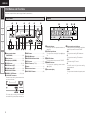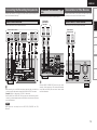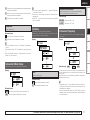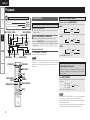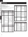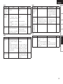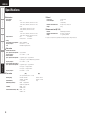
1
AV SURROUND RECEIVER
AVR-390
Owner’s Manual
Bedienungsanleitung
Manuel de l’Utilisateur
Manual del usuario
Инструкция по эксплуатации
Instrukcja Obsługi
Kullanım Kılavuzu
ENGLISH
DEUTSCH FRANCAIS ESPAÑOL
РУССКИЙ
nSAFETY PRECAUTIONS
CAUTION
RISK OF ELECTRIC SHOCK
DO NOT OPEN
CAUTION:
TO REDUCE THE RISK OF ELECTRIC SHOCK, DO NOT REMOVE
COVER (OR BACK). NO USER-SERVICEABLE PARTS INSIDE.
REFER SERVICING TO QUALIFIED SERVICE PERSONNEL.
The lightning flash with arrowhead symbol, within an equilateral
triangle, is intended to alert the user to the presence of
uninsulated “dangerous voltage” within the product’s enclosure
that may be of sufficient magnitude to constitute a risk of
electric shock to persons.
The exclamation point within an equilateral triangle is intended
to alert the user to the presence of important operating
and maintenance (servicing) instructions in the literature
accompanying the appliance.
WARNING:
TO REDUCE THE RISK OF FIRE OR ELECTRIC SHOCK, DO NOT
EXPOSE THIS APPLIANCE TO RAIN OR MOISTURE.
POLSKI
TÜRKÇE
nFor EU countries
CAUTION:
•DECLARATION OF CONFORMITY
We declare under our sole responsibility that this product, to which this
declaration relates, is in conformity with the following standards:
EN60065, EN55013, EN55020, EN61000-3-2 and EN61000-3-3.
Following the provisions of 2006/95/EC and 2004/108/EC Directive.
•ÜBEREINSTIMMUNGSERKLÄRUNG
Wir erklären unter unserer Verantwortung, daß dieses Produkt, auf das
sich diese Erklärung bezieht, den folgenden Standards entspricht:
EN60065, EN55013, EN55020, EN61000-3-2 und EN61000-3-3.
Entspricht den Verordnungen der Direktive 2006/95/EC und 2004/108/
EC.
•DECLARATION DE CONFORMITE
Nous déclarons sous notre seule responsabilité que l’appareil, auquel se
réfère cette déclaration, est conforme aux standards suivants:
EN60065, EN55013, EN55020, EN61000-3-2 et EN61000-3-3.
D’après les dispositions de la Directive 2006/95/EC et 2004/108/EC.
•DECLARACIÓN DE CONFORMIDAD
Declaramos bajo nuestra exclusiva responsabilidad que este producto al
que hace referencia esta declaración, está conforme con los siguientes
estándares:
EN60065, EN55013, EN55020, EN61000-3-2 y EN61000-3-3.
Siguiendo las provisiones de las Directivas 2006/95/EC y 2004/108/EC.
•СЕРТИФИКАТ СООТВЕТСТВИЯ
Мы гарантируем, что данный продукт, к которому прилагается данный
сертификат, соответствует требованиям следующих стандартов:
EN60065, EN55013, EN55020, EN61000-3-2 и EN61000-3-3.
Согласно условиям директив 2006/95/EC и 2004/108/EC.
•DEKLARACJA ZGODNOŚCI
Deklarujemy z pełną odpowiedzialnością, że produkt, którego dotyczy
niniejsza deklaracja, jest zgodny z następującymi normami:
EN60065, EN55013, EN55020, EN61000-3-2 oraz EN61000-3-3.
Zgodność z zaleceniami dyrektywy 2006/95/EC oraz 2004/108/EC.
•UYGUNLUK BEYANI
Sorumluluğu tamamen kendimize ait olarak; işbu beyan konusu ürünün
aşağıdaki standartlara uygun olduğunu beyan ederiz:
EN60065, EN55013, EN55020, EN61000-3-2 ve EN61000-3-3.
2006/95/EC ve 2004/108/EC sayılı Yönerge hükümlerini takiben.
DENON EUROPE
Division of D&M Germany GmbH
An der Landwehr 19, Nettetal,
D-41334 Germany
I
To completely disconnect this product from the mains, disconnect
the plug from the wall socket outlet.
The mains plug is used to completely interrupt the power supply
to the unit and must be within easy access by the user.
VORSICHT:
Um dieses Gerät vollständig von der Stromversorgung abzutrennen,
ziehen Sie bitte den Stecker aus der Wandsteckdose.
Der Netzstecker wird verwendet, um die Stromversorgung zum
Gerät völlig zu unterbrechen; er muss für den Benutzer gut und
einfach zu erreichen sein.
PRECAUTION:
Pour déconnecter complètement ce produit du courant secteur,
débranchez la prise de la prise murale.
La prise secteur est utilisée pour couper complètement
l’alimentation de l’appareil et l’utilisateur doit pouvoir y accéder
facilement.
PRECAUCIÓN:
Para desconectar completamente este producto de la alimentación
eléctrica, desconecte el enchufe del enchufe de la pared.
El enchufe de la alimentación eléctrica se utiliza para interrumpir por
completo el suministro de alimentación eléctrica a la unidad y debe
de encontrarse en un lugar al que el usuario tenga fácil acceso.
ОСТОРОЖНО:
Для того чтобы полностью отключить данный продукт от сети,
выньте штепсельную вилку кабеля питания из розеткиt.
При установке данного продукта убедитесь в том, что
используемая розетка находится в зоне досягаемости.
UWAGA:
W celu całkowitego odłączenia tego urządzenia od zasilania, należy
wyjąć wtyczkę z gniazda elektrycznego.
Przewód zasilający umożliwia całkowite odłączenie dopływu
zasilania do urządzenia i musi być łatwo dostępny dla
użytkownika.
DİKKAT:
Ürünün elektrikle bağlantısını tamamen kesmek için fişi, duvardaki
prizden çekiniz.
Elektrik prizi, cihaza gelen elektriği bütünüyle kesmek için
kullanılmakta olup kullanıcının kolayca erişebileceği bir yerde
olmalıdır.
TÜRKÇE
POLSKI
РУССКИЙ ESPAÑOL FRANCAIS DEUTSCH ENGLISH
nNOTE ON USE / HINWEISE ZUM GEBRAUCH / OBSERVATIONS RELATIVES A L’UTILISATION / NOTAS SOBRE EL USO /
ЗАМЕЧАНИЯ ПО ЭКСПЛУАТАЦИИ / WSKAZÓWKI DOTYCZĄCE OBSŁUGI / KULLANIM NOTLARI
CAUTION:
•The ventilation should not be impeded by covering the ventilation openings with items,
such as newspapers, tablecloths, curtains, etc.
•No naked flame sources, such as lighted candles, should be placed on the unit.
•Observe and follow local regulations regarding battery disposal.
•Do not expose the unit to dripping or splashing fluids.
•Do not place objects filled with liquids, such as vases, on the unit.
ACHTUNG:
•Do not let foreign objects into the unit.
•Keep the unit free from moisture, water, and dust.
•Lassen Sie keine fremden Gegenstände in das Gerät kommen.
•Avoid high temperatures.
•Halten Sie das Gerät von Feuchtigkeit, Wasser und Staub •Ne pas laisser des objets étrangers dans l’appareil.
Allow for sufficient heat dispersion when installed in a rack.
fern.
•No deje objetos extraños dentro del equipo.
•Vermeiden Sie hohe Temperaturen.
•Protéger l’appareil contre l’humidité, l’eau et la poussière. •Следите, чтобы посторонние предметы не попадали
Beachten Sie, dass eine ausreichende Belüftung gewährleistet •Mantenga el equipo libre de humedad, agua y polvo.
внутрь устройства.
wird, wenn das Gerät auf ein Regal gestellt wird.
•Не подвергайте устройство воздействию влаги, воды и •Zwróć uwagę, aby do środka urządzenia nie dostały się
•Eviter des températures élevées.
пыли.
żadne obce przedmioty.
Tenir compte d’une dispersion de chaleur suffisante lors de •Chroń urządzenie przed wilgocią, wodą i pyłem.
•Üniteye yabancı cisim girmesine izin vermeyiniz.
l’installation sur une étagère.
•Üniteyi nem, su ve tozdan uzak tutunuz.
•Evite altas temperaturas.
Permite la suficiente dispersión del calor cuando está
instalado en la consola.
•Избегайте высоких температур.
Учитывайте значительное распределение тепла при
установке устройства на полку.
•Unikaj wysokich temperatur.
Jeśli urządzenie jest ustawione w szafce, należy zapewnić
odpowiednią cyrkulację powietrza.
•Yüksek sıcaklıklardan kaçınınız.
Bir raf içinde kuruluysa yeterli ısı dağılımı olmasına dikkat •Unplug the power cord when not using the unit for long •Do not let insecticides, benzene, and thinner come in
periods of time.
contact with the unit.
ediniz.
•Wenn das Gerät längere Zeit nicht verwendet werden soll, •Lassen Sie das Gerät nicht mit Insektiziden, Benzin oder
trennen Sie das Netzkabel vom Netzstecker.
Verdünnungsmitteln in Berührung kommen.
•Débrancher le cordon d’alimentation lorsque l’appareil •Ne pas mettre en contact des insecticides, du benzène et
n’est pas utilisé pendant de longues périodes.
un diluant avec l’appareil.
•Desconecte el cordón de energía cuando no utilice el •No permita el contacto de insecticidas, gasolina y
equipo por mucho tiempo.
diluyentes con el equipo.
•Если устройство не будет использоваться в течение •Предохраняйте
устройство
от
воздействия
длительного времени, отключите кабель питания от сети.
ядохимикатов, бензина и растворителей.
•Odłącz przewód zasilający z sieci, jeśli urządzenie nie jest •Chroń urządzenie przed kontaktem z środkami
używane przez dłuższy czas.
owadobójczymi, benzyną oraz rozpuszczalnikiem.
•Ünite uzun süre kullanılmayacaksa ünitenin kablosunu •Böcek ilacı, benzen ve tiner gibi maddeleri üniteyle temas
•Handle the power cord carefully.
prizden
çekiniz.
ettirmeyiniz.
Hold the plug when unplugging the cord.
•Gehen Sie vorsichtig mit dem Netzkabel um.
Halten Sie das Kabel am Stecker, wenn Sie den Stecker
herausziehen.
•Manipuler le cordon d’alimentation avec précaution.
Tenir la prise lors du débranchement du cordon.
•Maneje el cordón de energía con cuidado.
Sostenga el enchufe cuando desconecte el cordón de
energía.
•Будьте осторожны при включении/отключении кабеля
* (For apparatuses with ventilation holes)
питания.
При включении/отключении кабеля питания беритесь за •Do not obstruct the ventilation holes.
•Never disassemble or modify the unit in any way.
вилку.
•Decken Sie den Lüftungsbereich nicht ab.
•Versuchen Sie niemals das Gerät auseinander zu nehmen
•Obchodź się ostrożnie z przewodem zasilającym.
•Ne pas obstruer les trous d’aération.
oder zu verändern.
Odłączając przewód z gniazda elektrycznego, trzymaj •No obstruya los orificios de ventilación.
•Ne jamais démonter ou modifier l’appareil d’une manière
zawsze za wtyczkę.
•Не закрывайте вентиляционные отверстия.
ou d’une autre.
•Güç kablosunu dikkatli kullanınız.
•Nie zakrywaj otworów wentylacyjnych.
•Nunca desarme o modifique el equipo de ninguna manera.
Kabloyu fişten çekerken prizden tutunuz.
•Havalandırma deliklerini kapatmayınız.
•Никогда не разбирайте и не модифицируйте
устройство.
•Nie rozbieraj urządzenia oraz nie dokonuj w nim żadnych
modyfikacji.
•Üniteyi asla hiçbir şekilde sökmeyiniz ve üzerinde değişiklik
yapmayınız.
•Die Belüftung sollte auf keinen Fall durch das Abdecken der Belüftungsöffnungen durch
Gegenstände wie beispielsweise Zeitungen, Tischtücher, Vorhänge o. Ä. behindert
werden.
•Auf dem Gerät sollten keinerlei direkte Feuerquellen wie beispielsweise angezündete
Kerzen aufgestellt werden.
•Bitte beachten Sie bei der Entsorgung der Batterien die örtlich geltenden
Umweltbestimmungen.
•Das Gerät sollte keiner tropfenden oder spritzenden Flüssigkeit ausgesetzt werden.
•Auf dem Gerät sollten keine mit Flüssigkeit gefüllten Behälter wie beispielsweise Vasen
aufgestellt werden.
ATTENTION:
•La ventilation ne doit pas être gênée en recouvrant les ouvertures de la ventilation avec
des objets tels que journaux, rideaux, tissus, etc.
•Aucune flamme nue, par exemple une bougie, ne doit être placée sur l’appareil.
•Veillez à respecter les lois en vigueur lorsque vous jetez les piles usagées.
•L’appareil ne doit pas être exposé à l’eau ou à l’humidité.
•Ne pas poser d’objet contenant du liquide, par exemple un vase, sur l’appareil.
PRECAUCIÓN:
•La ventilación no debe quedar obstruida por haberse cubierto las aperturas con objetos
como periódicos, manteles, cortinas, etc.
•No debe colocarse sobre el aparato ninguna fuente inflamable sin protección, como velas
encendidas.
•A la hora de deshacerse de las pilas, respete la normativa para el cuidado del medio
ambiente.
•No exponer el aparato al goteo o salpicaduras cuando se utilice.
•No colocar sobre el aparato objetos llenos de líquido, como jarros.
ОСТОРОЖНО:
•Не закрывайте вентиляционные отверстия такими предметами, как газеты, скатерти,
шторы и др.
•Не размещайте на поверхности аппарата источники открытого огня, например
свечи.
•Обратите внимание на экологические аспекты утилизации батарей питания.
•Следите, чтобы на устройство не проливалась вода.
•Не располагайте емкости, в которых содержится вода, на устройстве.
UWAGA:
•Nie należy ograniczać wentylacji urządzenia, np. poprzez zakrycie otworów wentylacyjnych
gazetami, obrusem, zasłonami itp.
•Na urządzeniu nie wolno stawiać żadnych źródeł otwartego ognia, np. zapalonych świec.
•Przestrzegaj lokalnych przepisów dotyczących utylizacji baterii.
•Chroń urządzenie przez zachlapaniem lub kapaniem wszelkich cieczy.
•Nie stawiaj na urządzeniu żadnych przedmiotów napełnionych wodą, np. wazonów.
DİKKAT:
•Havalandırma gazete, masa örtüsü, perde ve benzeri cisimlerle kapatılarak
engellenmemelidir.
•Yanan mum gibi açık alev kaynağı cisimleri üniteye yaklaştırmayınız.
•Pillerin atılması ile ilgili yerel yasa ve düzenlemelere riayet ediniz.
•Üniteyi, üzerine sıvı damlama veya sıçrama ihtimali olan yerlerde bulundurmayınız.
•Vazo gibi sıvıyla dolu cisimleri ünitenin üzerine koymayınız.
II
ENGLISH
DEUTSCH FRANCAIS ESPAÑOL
РУССКИЙ
POLSKI
TÜRKÇE
A NOTE ABOUT RECYCLING:
This product’s packaging materials are recyclable and can be reused. Please dispose of any
materials in accordance with the local recycling regulations.
When discarding the unit, comply with local rules or regulations.
Batteries should never be thrown away or incinerated but disposed of in accordance with the local
regulations concerning battery disposal.
This product and the supplied accessories, excluding the batteries, constitute the applicable
product according to the WEEE directive.
HINWEIS ZUM RECYCLING:
Das Verpackungsmaterial dieses Produktes ist zum Recyceln geeignet und kann wieder verwendet
werden. Bitte entsorgen Sie alle Materialien entsprechend der örtlichen Recycling-Vorschriften.
Beachten Sie bei der Entsorgung des Gerätes die örtlichen Vorschriften und Bestimmungen.
Die Batterien dürfen nicht in den Hausmüll geworfen oder verbrannt werden; bitte entsorgen Sie
die Batterien gemäß der örtlichen Vorschriften.
Dieses Produkt und das im Lieferumfang enthaltene Zubehör (mit Ausnahme der Batterien!)
entsprechen der WEEE-Direktive.
UNE REMARQUE CONCERNANT LE RECYCLAGE:
Les matériaux d’emballage de ce produit sont recyclables et peuvent être réutilisés. Veuillez
disposer des matériaux conformément aux lois sur le recyclage en vigueur.
Lorsque vous mettez cet appareil au rebut, respectez les lois ou réglementations en vigueur.
Les piles ne doivent jamais être jetées ou incinérées, mais mises au rebut conformément aux lois
en vigueur sur la mise au rebut des piles.
Ce produit et les accessoires inclus, à l’exception des piles, sont des produits conformes à la
directive DEEE.
ACERCA DEL RECICLAJE:
Los materiales de embalaje de este producto son reciclables y se pueden volver a utilizar. Disponga de estos
materiales siguiendo los reglamentos de reciclaje de su localidad.
Cuando se deshaga de la unidad, cumpla con las reglas o reglamentos locales.
Las pilas nunca deberán tirarse ni incinerarse. Deberá disponer de ellas siguiendo los reglamentos de su localidad
relacionados con los desperdicios químicos.
Este producto junto con los accesorios empaquetados es el producto aplicable a la directiva RAEE excepto pilas.
ПРИМЕЧАНИЕ О ПЕРЕРАБОТКЕ:
Упаковочный материал данного продукта может быть переработан и повторно использован. Пожалуйста,
сортируйте материалы в соответствии с местными требованиями переработки.
При утилизации определенных блоков соблюдайте местные правила утилизации.
Не выбрасывайте и не сжигайте батарейки, соблюдайте местные правила утилизации химических отходов.
Данный продукт и аксессуары в упаковке соответствуют директиве WEEE, исключая батарейки.
INFORMACJE DOTYCZĄCE RECYKLINGU:
Opakowanie urządzenia zostało wykonane z materiałów nadających się do wtórnego przetworzenia. Utylizację wszelkich
materiałów należy przeprowadzić zgodnie z obowiązującymi lokalnymi przepisami dotyczącymi recyklingu.
Urządzenie należy zutylizować zgodnie z lokalnymi przepisami.
Baterii nie wolno wyrzucać do śmieci lub palić. Należy je zutylizować zgodnie z obowiązującymi zasadami dotyczącymi
utylizacji baterii.
Niniejszy produkt oraz dostarczone wraz z nim akcesoria (oprócz baterii) stanowią właściwy produkt, zgodnie z
dyrektywą WEEE.
GERİ DÖNÜŞÜME İLİŞKİN NOT:
Bu ürünün ambalajı geri dönüştürülebilir ve yeniden kullanılabilir niteliktedir. Materyalleri lütfen yerel geri dönüşüm
yasa ve düzenlemelerine uygun biçimde atınız.
Üniteyi hurdaya çıkartırken mahalli yasa ve düzenlemelere riayet ediniz.
Piller asla rastgele atılmamalı ve yakılmamalı, bunun yerine pil atıklarına ilişkin mahalli yasa ve düzenlemelere uygun
biçimde imha edilmelidir.
Bu ürün ve beraberinde gelen aksesuarları, pilleri hariç olmak kaydıyla, WEEE yönergesi uyarınca kapsam içi ürün
niteliğindedir.
III
ENGLISH
nContents
Getting Started
Accessories······················································································· 2
Cautions on Handling······································································ 2
Cautions on Installation·································································· 2
About the Remote Control Unit····················································· 3
Inserting the Batteries···································································· 3
Operating Range of the Remote Control Unit································ 3
Part Names and Functions······························································ 4
Front Panel······················································································ 4
Display···························································································· 4
Rear Panel······················································································· 5
Remote Control Unit (RC-1115)······················································ 6
Connections
Preparations····················································································· 7
Cables Used for Connections························································· 7
Speaker Connections······································································ 8
Speaker Installation········································································ 8
Speaker Connections····································································· 8
Connecting Equipment with HDMI Connectors·························· 10
Connecting the Monitor································································ 11
Connecting the Playback Components········································ 11
DVD Player···················································································· 11
CD Player······················································································ 12
iPod®· ·························································································· 12
TV/CABLE Tuner············································································ 12
Connecting the Recording Components····································· 13
Video Cassette Recorder······························································ 13
CD Recorder / MD Recorder / Tape Deck···································· 13
Connections to Other Devices······················································ 13
Video Camera / Game Console···················································· 13
Component with Multi-channel Output Connectors···················· 14
Antenna Terminals ······································································· 14
Connecting the Power Cord························································· 14
Once Connections are Completed··············································· 14
Operations
Menu Map······················································································ 15
Menu Operations
Operations······················································································ 15
Example of Display of Default Values·········································· 15
System Setup
Power On Level·············································································· 16
Surround Modes
Selecting the Surround Mode······················································ 19
Stereo Playback············································································· 19
Parameter
Tone Control·················································································· 20
Bass······························································································ 20
Treble···························································································· 20
Night Mode···················································································· 21
Dolby PLg Music············································································ 21
Panorama······················································································ 21
Center Width················································································ 21
Dimension···················································································· 21
iPod Assign
Assign····························································································· 16
Speaker Setup
Speaker Configuration·································································· 16
Front Speaker··············································································· 16
Center Speaker············································································· 16
Surround Speaker········································································· 16
Subwoofer···················································································· 17
Subwoofer Mode Setup································································ 17
Distance·························································································· 17
Unit······························································································· 17
Distance measurement································································ 17
Crossover Frequency····································································· 17
Channel Level Setup
Adjusting the Current Channel Level··········································· 18
Memorizing the Adjusted Channel Levels··································· 18
Select the Channel Level······························································· 18
Information·········································································· 21
Playback
Preparations··················································································· 22
Turning the Power On·································································· 22
Selecting the Input Source··························································· 22
Switching between Digital Audio Input and
Analog Audio Input······································································· 22
Operations During Playback························································· 23
Playing Video and Audio Equipment··········································· 23
Basic Operation············································································ 23
Listening to FM/AM Broadcasts··················································· 23
Basic Operation············································································ 23
Automatically Presetting FM Stations (Auto Preset)···················· 23
Presetting FM/AM Stations Manually·········································· 24
Listening to Preset Stations························································· 24
Performing Preset Search···························································· 24
RDS (Radio Data System)····························································· 24
RDS Search··················································································· 25
PTY Search··················································································· 25
TP Search······················································································ 25
iPod® Playback·············································································· 26
Preparations·················································································· 26
Listening to Audio········································································ 26
Viewing Still Pictures or Videos on the iPod································ 27
ENGLISH
Getting Started
Other Operations and Functions
Connections
Other Operations··········································································· 28
Recording on an External Device················································· 28
Convenient Functions··································································· 28
Adjusting Each Channel Level with Test Tone····························· 28
Personal Memory Plus Function·················································· 29
Last Function Memory································································· 29
Backup Memory··········································································· 29
Setup
Special Mode
Playback
Resetting the Microprocessor······················································ 29
Tuning Interval Change································································· 29
Information
Other Information··························································· 30
Troubleshooting······························································· 32
Troubleshooting
Specifications···································································· 34
Cautions on Handling
Getting Started
Thank you for purchasing this DENON product. To ensure proper
operation, please read this owner’s manual carefully before using the
product.
After reading them, be sure to keep them for future reference.
Accessories
Check that the following parts are supplied with the product.
qOwner’s manual....................................................................... 1
wGetting Started......................................................................... 1
eService station list.................................................................... 1
rRemote control unit (RC-1115)................................................ 1
tR03/AAA batteries.................................................................... 2
yFM indoor antenna................................................................... 1
uAM loop antenna...................................................................... 1
r
y
u
•Before turning the power switch on
Check once again that all connections are correct and that there are
no problems with the connection cables.
•Power is supplied to some of the circuitry even when the unit is
set to the standby mode. When traveling or leaving home for long
periods of time, be sure to unplug the power cord from the power
outlet.
•About condensation
If there is a major difference in temperature between the inside of
the unit and the surroundings, condensation (dew) may form on
the operating parts inside the unit, causing the unit not to operate
properly.
If this happens, let the unit sit for an hour or two with the power
turned off and wait until there is little difference in temperature
before using the unit.
•Cautions on using mobile phones
Using a mobile phone near this unit may result in noise. If so, move
the mobile phone away from this unit when it is in use.
•Moving the unit
Turn off the power and unplug the power cord from the power
outlet.
Next, disconnect the connection cables to other system units
before moving the unit.
Specifications
•Note that the illustrations in these instructions may differ from the
actual unit for explanation purposes.
Cautions on Installation
Note:
For proper heat dispersal, do not install this unit in a confined
space, such as a bookcase or similar enclosure.
b
bNote
b
b
Wall
ENGLISH
Inserting the Batteries
Operating Range of the Remote Control
Unit
Getting Started
About the Remote Control Unit
Point the remote control unit at the remote sensor when operating
it.
Connections
q Lift the clasp and remove the rear cover.
Setup
w Load the two batteries properly as indicated
by the marks in the battery compartment.
30°
Playback
30°
R03/AAA
e Put the rear cover back on.
Information
Approx. 7 m
NOTE
NOTE
The set may function improperly or the remote control unit may not
operate if the remote control sensor is exposed to direct sunlight,
strong artificial light from an inverter type fluorescent lamp or infrared
light.
Troubleshooting
Specifications
•Replace the batteries with new ones if the set does not operate
even when the remote control unit is operated close to the unit.
•The supplied batteries are only for verifying operation.
•When inserting the batteries, be sure to do so in the proper direction,
following the “q” and “w” marks in the battery compartment.
•To prevent damage or leakage of battery fluid:
•Do not use a new battery together with an old one.
•Do not use two different types of batteries.
•Do not attempt to charge dry batteries.
•Do not short-circuit, disassemble, heat or dispose of batteries in
flames.
•If the battery fluid should leak, carefully wipe the fluid off the inside
of the battery compartment and insert new batteries.
•Remove the batteries from the remote control unit if it will not be in
use for long periods.
•When replacing the batteries, have the new batteries ready and
insert them as quickly as possible.
ENGLISH
Getting Started
Part Names and Functions
For buttons not explained here, see the page indicated in parentheses ( ).
Connections
Front Panel
Q7
Display
Q6
Q5
Q4
Q3
Q2
y
t
r
e
Setup
Playback
Information
q
q
w
e rt
y u i
Troubleshooting
qPower operation button
(ON/STANDBY)············································ (22)
Specifications
wPower indicator··········································· (22)
eHeadphone jack (PHONES)························· (23)
rSTATUS button······································ (21, 23)
tPRESET buttons (df) ································· (24)
yTUNING buttons (df)································· (23)
uDIGITAL INPUTS button······························ (22)
iMEMORY / ENTER button·············· (15, 18, 24)
oV. AUX INPUT connectors
Remove the cap covering the connectors when
you want to use them.
Fit the cap when not using the V.AUX INPUT
connectors. Fitting the cap keeps out dust, etc.
o
Q0
Q1
Q0NIGHT button··············································· (21)
Q1SURROUND buttons··································· (19)
Q2MASTER VOLUME control knob················ (23)
Q3SETUP button·············································· (15)
Q4SELECT buttons (uio p)························· (15)
Q5Display···························································· (4)
Q6Remote control sensor·································· (3)
Q7INPUT SELECT buttons······························· (22)
w
qDecoder indicators
yTuner reception mode indicators
These light when the respective decoders are
operating.
wDIGITAL input indicator
This lights when set to digital input (vpage
22).
ePRESET indicator
This lights when the input source is “TUNER”.
rMEMORY indicator
This lights when registering preset numbers
(vpage 23).
tInformation display
These light according to the reception conditions
when the input source is set to “TUNER”.
•RDS
This lights when receiving RDS broadcasts.
•TP
This lights when receiving TP broadcasts.
•PTY
This flashes during PTY search.
•ST.
In the FM mode, this lights when receiving
stereo broadcasts.
•TUNED
This lights when the broadcast is properly tuned
in.
ENGLISH
Q1
Q0
Getting Started
Rear Panel
i
o
Connections
Setup
Playback
Information
w
e
r
t
y
tFM/AM antenna terminals
wEXT. IN connectors······································ (14)
eAnalog audio connectors
yVIDEO / S-VIDEO connectors············· (11 ~ 13)
uSpeaker terminals (SPEAKERS)···················· (8)
iPower cord··················································· (14)
oCOMPONENT VIDEO connectors······· (11 ~ 13)
(OPTICAL / COAXIAL)························· (10 ~ 13)
(AUDIO)················································ (10 ~ 13)
rPRE OUT connector······································· (8)
(TUNER ANTENNA)····································· (14)
u
Specifications
qDigital audio connectors
Troubleshooting
q
Q0HDMI connectors································· (10 ~ 13)
Q1DOCK CONTROL jack·································· (12)
ENGLISH
Getting Started
Remote Control Unit (RC-1115)
q
Connections
w
Q5
Setup
e
Playback
r
Information
Q6
Q7
Q8
t
y
u
Troubleshooting
i
d
Q9
o
Q0
Q1
Specifications
Q2
Q3
Q4
f
W0
W1
W2
W3
W4
qRemote control signal transmitter··············· (3)
wPower buttons············································· (22)
eNumber buttons·········································· (24)
rPRESETS button·········································· (24)
tTest Tone button (TEST)······························ (28)
yDigital Input button (D. INPUTS)················ (22)
uSURROUND PARAMETER button··············· (21)
iSETUP button·············································· (15)
oSelect buttons (uio p)···························· (15)
Q0Memory (MEMO) / ENTER button··· (15, 18, 24)
Q1Channel select button (CH SEL)················· (18)
Q2NIGHT button··············································· (21)
Q3STEREO button············································ (19)
Q4SURROUND buttons (0 1)························ (19)
Q5Input select buttons···································· (22)
Q6BAND button················································ (23)
Q7STATUS button······································ (21, 23)
Q8DIMMER button··········································· (23)
Q9Master volume control buttons·················· (23)
W0TONE button················································ (20)
W1MUTE button················································ (23)
W2SEARCH button····································· (25, 26)
W3CHANNEL (+ –) buttons······························· (24)
W4System button for iPod use························ (27)
ENGLISH
Getting Started
Connections
Select the cables according to the equipment being connected.
Audio cables
Video cables
Coaxial digital connections
Component video connections
(Green)
(Orange)
(Blue)
(PB/CB)
(Red)
(PR/CR)
Component video cable
Optical digital connections
Analog connections (stereo)
S-Video cable
L
L
R
R
Stereo pin-plug cable
Video connections
Specifications
(Red)
Troubleshooting
S-Video connections
Optical cable
(White)
(Y)
Information
Coaxial digital (75 Ω/ohms pin-plug) cable
Playback
•Do not plug in the power cord until all connections have been
completed.
•When making connections, also refer to the operating instructions
of the other components.
•Be sure to connect the left and right channels properly (left with left,
right with right).
•Do not bundle power cords together with connection cables. Doing
so can result in humming or noise.
Cables Used for Connections
Setup
NOTE
Preparations
Connections
Connections for all compatible audio and video signal formats
are described in this owner’s manual. Please select the types of
connections suited for the equipment you are connecting.
With some types of connections, certain settings must be made
on the AVR-390. For details, refer to the instructions for the
respective connection items below.
(Yellow)
75 Ω/ohms pin-plug video cable
Analog connections (monaural, for subwoofer)
(Black)
Audio and video cables
Pin-plug cable
Speaker connections
HDMI connections
19-pin HDMI cable
Signal direction
Speaker cables
Audio signal:
Video signal:
Output
Input
Input
Output Output
Input
Input
Output
ENGLISH
Getting Started
Speaker Connections
Speaker Connections
Speaker Installation
Subwoofer
Connections
The illustration below shows a basic example of installation of the AVR-390 combined with 6 speakers
and a monitor.
Subwoofer
Front speakers
Subwoofer
with built-in
amplifier
Center speaker
(L)
w
Setup
*/
Center speaker
(R)
q
w
q
w
q
Playback
Information
Troubleshooting
Specifications
Front speakers
Place the front speakers to the
sides of the monitor or screen and
as flush with the screen surface as
possible.
Surround speakers
bL : Left
R : Right
(L)
The table below shows a typical speaker configuration for the AVR-390.
FRONT
L
R
5.1-channels
S
S
3.1-channels
S
2.1-channels
2-channels
CENTER
w
SURROUND
SUBWOOFER
L
R
S
S
S
S
S
S
–
–
S
S
S
–
–
–
S
S
S
–
–
–
–
(R)
qw
q
Surround speakers
ENGLISH
Connecting the Speaker Cables
Peel off the sheath from the tip
Turn the speaker terminal counterclockwise
Insert the speaker cable’s core wire to the
Turn the speaker terminal clockwise to
Information
hilt into the speaker terminal.
Playback
to loosen it.
Setup
2
3
4
Sheath
of the speaker cable, then firmly
twist the wires by hand so that they
do not stick out and cause shortcircuits.
If the core wires touch the rear panel and the screws etc., or the ±
sides touch each other, the protection circuit will be activated and
the power indicator will flash red at intervals of 0.5 secs.
If the protection circuit is activated, the speaker output is isolated,
and the power supply goes to the standby state. If the power
supply is turned off, after the power cord is withdrawn, please
confirm that speaker cable and input cable are connected.
Also, if replaying large sound levels by using a speaker having an
impedance less than that specified (eg, 4 Ω/ohms), the temperature
will rise, and the protection circuit might be activated. The power
supply will go into the standby state, and the power indicator will
flash red at 2 second intervals.
In this case, please switch off the power supply, and wait until the
AVR-390 has cooled down, and the surrounding ventilation is good.
Even if there are no problems with the surrounding ventilation
and connections, in the event of the protection circuit becoming
activated, due to thinking that the AVR-390 has failed, please
contact DENON Service center after switching off.
Connections
1
Getting Started
Protection circuit
Carefully check the left (L) and right (R) channels and + (red) and
– (black) polarities on the speakers being connected to the AVR-390,
and be sure to interconnect the channels and polarities correctly.
tighten it.
Troubleshooting
NOTE
Specifications
•Use speakers with an impedance of 6 to 16 Ω/ohms.
•Connect the speaker cables in such a way that they do not stick out
of the speaker terminals. The protection circuit may be activated if
the core wires touch the rear panel or if the + and – sides touch each
other (v“Protection circuit”).
•Never touch the speaker terminals while the power supply is
connected. Doing so could result in electric shock.
ENGLISH
Getting Started
Connecting Equipment with HDMI Connectors
NOTE
Connections
When HDMI input signals are sent to the monitor as HDMI output, both video and audio are output to
the monitor.
NOTE
The audio signal input to the HDMI input connector cannot be played on the AVR-390. Input the
audio signal to the digital audio input connector or analog audio input connector.
Setup
DVD player
Monitor
•The AVR-390 cannot be controlled from another device via the HDMI cable.
•Video signals are not output if the input video signals do not match the monitor’s resolution. In this
case, switch the DVD player’s resolution to a resolution with which the monitor is compatible.
•Use a cable on which the HDMI logo is indicated (a certified HDMI product) for connection to the HDMI
connector. Normal playback may not be possible when using a cable other than one on which the HDMI
logo is indicated (a non-HDMI-certified product).
•If the monitor or DVD player does not support Deep Color, deep color signal transfer is not possible.
•If the monitor or DVD player does not support xvYCC, xvYCC signal transfer is not possible.
Playback
"6%*0
"6%*0
065
3
Information
Troubleshooting
L
R
L
R
$0"9*"065
)%.*
065
)%.*
*/
•The audio and video signals input to the AVR-390’s HDMI input connector are output unchanged from
the HDMI output connector. Because of this, the sound is output from the monitor connected using the
HDMI connectors, but in order to take full advantage of the AVR-390’s playback sound, turn the TV’s
volume down.
•If the connected monitor or DVD player only has a DVI-D connector, use an HDMI/DVI converter cable.
When using a DVI cable, no audio signals are transmitted.
•Use a Deep Color compatible cable for connection to Deep Color compatible devices.
When connecting with an HDMI/DVI converter cable (adapter)
Specifications
•HDMI video signals are theoretically compatible with the DVI format.
When connecting to a monitor, etc., equipped with a DVI-D connector, connection is possible using
an HDMI/DVI converter cable, but depending on the combination of components in some cases the
video signals will not be output.
•When connecting using an HDMI/DVI converter adapter, the video signals may not be output properly
due to poor connections with the connected cable, etc.
bThe AVR-390 is equipped for HDMI version 1.3a. This version is compatible with other versions, allowing
connection to all components equipped with an HDMI connector.
bThe AVR-390 is compatible with 30- and 36-bit Deep Color.
bThe AVR-390 can be connected to a device equipped with an HDMI output connector using an HDMI
cable.
bThe AVR-390 is compatible with HDMI Ver. 1.3a Deep Color and xvYCC.
10
ENGLISH
Connecting the Playback Components
Select the terminal to use and connect the device.
Monitor
NOTE
7*%&0
*/
$0.10/&/57*%&0
*/
:
1# 13
)%.*
*/
DVD Player
Select the terminal to use and connect the device.
DVD player
NOTE
"6%*0
R
L
R
)%.*
065
$0.10/&/57*%&0
065
:
1# 13
7*%&0
065
47*%&0
065
The audio signal input to
the HDMI input connector
cannot be played on the
AVR-390. Input the audio
signal to the digital audio
input connector or analog
audio input connector.
Troubleshooting
Specifications
GFlow of video signals inside the AVR-390H
High picture
quality playback
HDMI connector
HDMI connector
Component video
connectors
Component video
connectors
Monitor
The same method can be used to connect an HDP (High-Definition Player) such as a Blu-ray Disc player.
NOTE
S-Video connector
S-Video connector
Video connector
Video connector
Video input terminals
Monitor output
terminals
Information
L
$0"9*"065
Playback
"6%*0
065
3
7*%&0
Setup
•The AVR-390 supports four video
input formats: HDMI, component
video, S-Video and video.
Because video signals are output
from the AVR-390’s monitor output
terminal in the same format as the
video input signals, the monitor
output terminal should be of the
same type as the terminal used
for input.
•The component video connectors
may be indicated differently on
your monitor. For details, see the
monitor’s operating instructions.
•To play the sound by AVR-390,
make analog or digital audio output
connections to AVR-390’s audio
input connectors.
Connections
7*%&0
47*%&0
*/
Carefully check the left (L) and right (R) channels and the inputs and outputs, and be sure to interconnect
correctly.
Getting Started
Connecting the Monitor
Because video signals are output from the AVR-390’s monitor output terminal in the same format as the
video input signals, the monitor output terminal should be of the same type as the terminal used for
input.
11
ENGLISH
Getting Started
iPod®
CD Player
Select the terminal to use and connect the device.
CD player
"6%*0
Connections
$0"9*"065
"6%*0
065
3
Setup
L
TV/CABLE Tuner
Use a DENON control dock for iPod (ASD-1R, ASD-11R, ASD-3N or
ASD-3W, sold separately) to connect the iPod to the AVR-390. For
instructions on the control dock for iPod settings, refer to the control
dock for iPod’s operating instructions.
iPod
R
ASD-3N or
"4%/8
ASD-3W
Select the terminal to use and connect the device.
NOTE
The audio signal input to the HDMI input connector cannot be
played on the AVR-390. Input the audio signal to the digital audio
input connector or analog audio input connector.
TV Tuner
"6%*0
015*$"-
Playback
065
L
7*%&0
"6%*0
065
3
47*%&0
065
7*%&0
065
$0.10/&/57*%&0
065
:
1# 13
)%.*
065
R
R
Information
R
L
L
R
L
R
L
Troubleshooting
Specifications
•With the default settings, the iPod can be used connected to the
VCR (iPod) connector.
•To assign the iPod to a connector other than VCR (iPod), make the
settings at “iPod Assign” – “Assign” (vpage 16).
NOTE
To playback iPod Video or Photos on a TV monitor, connect the
TV to the S-Video Out terminal of AVR-390.
12
NOTE
Because video signals are output from the AVR-390’s monitor output
terminal in the same format as the video input signals, the monitor
output terminal should be of the same type as the terminal used
for input.
ENGLISH
Carefully check the left (L) and right (R) channels and the inputs and outputs, and
be sure to interconnect correctly.
"6%*0
Video cassette recorder
L
R
7*%&0
065
$0.10/&/57*%&0
065
:
1# 13
)%.*
065
7*%&0
*/
"6%*0
*/
3
L
L
L
R
L
R
L
R
L
R
Select the terminal to use and connect the device.
Video camera /
Game console
7*%&0
"6%*0
7*%&0
065
"6%*0
065
3
R
L
R
L
R
Information
L
R
47*%&0
065
"6%*0
Video Camera / Game Console
Playback
"6%*0
065
3
7*%&0
"6%*0
065
3
Carefully check the left (L) and right (R) channels and the inputs
and outputs, and be sure to interconnect correctly.
Setup
065
7*%&0
"6%*0
*/
3
Connections to Other Devices
Connections
Select the terminal to use and connect the device.
015*$"-
Select the terminal to use and connect the device.
CD recorder /
MD recorder /
Tape deck
Video Cassette Recorder
"6%*0
CD Recorder / MD Recorder / Tape
Deck
Getting Started
Connecting the Recording Components
R
Troubleshooting
Specifications
•When recording via the AVR-390, the playback device’s cable must be of the
same type as the cable used to connect the AVR-390’s VCR OUT connector.
Example:DVD IN → Video cable : VCR OUT → Video cable
•Connect AUDIO and VIDEO VCR OUT terminals when video recording. When
connecting a video cassette recorder to AVR-390, be sure also to connect these
terminals beforehand.
Connect AUDIO CD-R/TAPE OUT terminals when audio
recording. When connecting a CD recorder, MD recorder
or tape deck to AVR-390, be sure also to connect these
terminals beforehand.
NOTE
Digital signals are not output from the REC OUT (CD-R/TAPE and VCR)
connector.
13
ENGLISH
Getting Started
Component with Multi-channel Output
Connectors
An FM antenna cable plug can be connected directly.
Select the terminal to use and connect the device.
Direction of broadcasting station
Connections
DVD player / External decoder
AM loop antenna
(supplied)
"6%*0
$&/5&3
463306/%
-
Setup
L
Playback
L
3
R
R
46#
800'&3
'30/5
-
L
L
NOTE
Antenna Terminals
FM antenna
Connecting the Power Cord
3
75 Ω/ohms
Coaxial cable
R
Information
Troubleshooting
AM outdoor
antenna
To household
power outlet
(AC 230 V, 50 Hz)
Specifications
-a
-b
Mount
Installation hole Mount on wall, etc.
q :Remove the vinyl tie and take out the connection line.
w :Bend in the reverse direction.
e-a:With the antenna on top of any stable surface.
e-b:With the antenna attached to a wall.
Connection of AM antennas
1.Push the lever.
Power cord
Ground
nAM loop antenna assembly
14
Wait until all connections have been completed before connecting
the power cord.
FM indoor
antenna
(supplied)
R
•To play the analog input signals input to the EXT. IN connectors,
press the EXT. IN button (vpage 22).
•The video signal can be connected in the same way as a DVD player
(vpage 11).
•To play copyright-protected discs, connect the AVR-390’s EXT.
IN connector with the DVD player’s analog multi-channel output
connector.
•Do not connect two FM antennas simultaneously.
•Even if an external AM antenna is used, do not disconnect the AM
loop antenna.
•Make sure the AM loop antenna lead terminals do not touch metal
parts of the panel.
2.Insert the conductor. 3.Return the lever.
NOTE
Insert the AC plugs securely. Incomplete connections could cause
noise.
Once Connections are Completed
Turning the Power On (vpage 22)
ENGLISH
Menu Operations
Symbols used to indicate buttons in this manual
System Setup (vpage 16)
nAssign
ENTER
SETUP
ui again to select the item you want to set,
then press ENTER.
Press
To change the setting:
Press ui to select the item you want to change, then
press o p to change the setting.
nTo move to a setup item of another category
Press ui to select “RETURN“, then press ENTER.
Specifications
nTo exit setup
Press SETUP while the setup menu is displayed.
nAdjusting the Current Channel Level
nMemorizing the Adjusted Channel Levels
nSelect the Channel Level
•The display returns to normal.
Parameter (vpage 20, 21)
nDolby PLg Music
•Panorama
•Center Width
•Dimension
ui to select the item you want to set, then
press ENTER.
Press
•Returns to the setup menu.
•Perform steps 3 and 4.
Channel Level Setup (vpage 18)
nTone Control
•Bass
•Treble
nNight Mode
“SYSTEM” is displayed.
SETUP
uio p
d
ENTER
Example of Display of Default
Values
f
In lists of selectable items or adjustable ranges, the item
surrounded by a border is the default value.
[Selectable items] S
Troubleshooting
nSubwoofer Mode Setup
nDistance
•Unit
•Distance measurement
nCrossover Frequency
Press SETUP.
Information
Speaker Setup (vpage 16, 17)
1
2
3
4
Playback
o p ui
iPod Assign (vpage 16)
The same operation is possible on the main unit or remote control
unit.
Setup
nPower On Level
Button located on both the main unit and the remote
control unit
BUTTON
Button only on the main unit
<BUTTON>
Button only on the remote control unit
[BUTTON]
Operations
Connections
Menu Map
nSpeaker Configuration
•Front Speaker
•Center Speaker
•Surround Speaker
•Subwoofer
Getting Started
Operations
L
15
ENGLISH
Getting Started
Connections
System Setup
iPod Assign
Speaker Setup
Power On Level
Assign
Speaker Configuration
This sets the volume set when the main zone’s power is turned
on.
Assign control dock for iPod to this source.
Select speaker configuration and size (bass reproduction capability).
[Display]
[Display]
[Display]
Setup
Playback
Information
[Variable range]
Troubleshooting
LAST
:Displays the volume before the power was turned off.
0 ~ 60 :Set the volume level when the power is turned on in units
of 1 dB.
[Assignable input source]
VCR
DVD
CD
CD-R / TAPE
z1
AUX
V.AUX
z2
OFF
z1:The display shows “CDR”.
z2:The display shows “V.A”.
Specifications
•The display shows “MIN” when you select “0 dB”.
•When the volume is 60 dB or more, a 60 dB volume is resumed when
you turn the power off and then on again.
Front Speaker
Select front speaker size.
[Selectable items] L
S
Center Speaker
Select center speaker use and size.
[Selectable items] L
S
N
Surround Speaker
Select surround speakers use and size.
[Selectable items] L
16
For details on how to select, set and cancel settings for each menu, see “Menu Operations” (vpage 15).
S
N
ENGLISH
reproduction capabilities.
S :Select this when using small speakers without ample low
frequency reproduction capabilities.
Distance measurement
Select the speaker you want to set, then set the distance.
Set the value closest to the measured distance.
[Variable range]
0.0 ~ 9.0 M :Display when “M” is set.
0 ~ 30 FT
Subwoofer
[Selectable items]
N :Select this when no subwoofer is connected.
Set distance from listening position to speakers.
Before making the settings, measure the distance from the
listening position to the different speakers.
[Display]
Crossover Frequency
Select crossover frequency from which subwoofer handles low
range signal.
[Display]
Information
Troubleshooting
•When “Front Speaker” is set to “S”, “Subwoofer” is automatically
set to “Y”.
•If “Subwoofer” is set to “N”, “Front Speaker” is automatically set to
“L”.
•When “Front Speaker” is set to “S”, “Center Speaker” and “Surround
Speaker” can not be set to “L”.
[Variable range]
Select low range signal to be reproduced by subwoofer.
Unit
Select unit for distance.
[Selectable items]
40HZ
~
120HZ
~
130HZ
Only the portion of the bass sound of the various speakers output
from the subwoofer that has a frequency below the frequency set
here is output.
Set this according to the low frequency reproduction capabilities of
the speakers you are using.
M :Displays the distance setting in meters.
FT :Displays the distance setting in feet.
[Selectable items]
NORM :Play low range and LFE signal of channels set to “S”.
SW+
:Play low range and LFE signal of all channels.
•For speakers set to “S”, sound below the crossover frequency is
cut from the sound output. The cut bass sound is output from the
subwoofer or front speakers.
•Always set the crossover frequency to “120HZ”. When using small
speakers, however, we recommend setting the crossover frequency
to a higher frequency.
For details on how to select, set and cancel settings for each menu, see “Menu Operations” (vpage 15).
17
Specifications
Subwoofer Mode Setup
[Display]
Playback
Y :Select this when a subwoofer is connected.
Distance
:Display when “FT” is set.
Setup
Select subwoofer use.
Connections
N :Select this when no speaker is connected.
•This can be set when “Speaker Setup” – “Speaker Configuration”
– “Subwoofer” is set to “Y”.
•Play music or a movie source and select the mode offering the
strongest bass.
•Select “SW+” if you want the bass signals to always be produced
from the subwoofer.
Getting Started
L :Select this when using large speakers with ample low frequency
ENGLISH
Getting Started
Channel Level Setup
Adjust channel levels to obtain equal volume from all speakers.
Connections
Symbols used to indicate buttons in this manual
Setup
Button located on both the main unit and the remote
control unit
BUTTON
Button only on the main unit
<BUTTON>
Button only on the remote control unit
[BUTTON]
[Display]
wPress o p to adjust the level of the selected channel or program
source’s LFE as desired.
[Variable range]
Other level : –15dB
~
0dB
LFE level : –10dB
~
0dB
~
+15dB
bIn general, we recommend the LFE level to be adjusted to 0
dB. (However, the recommended LFE level for some early DTS
software is −10 dB.) If the recommended levels seem too high,
lower setting as necessary.
Playback
o p ui
eRepeat the above steps 1 and 2 to adjust each channel level.
Information
NOTE
Troubleshooting
MEMORY/ENTER
Speaker set to “N” in the “Speaker Configuration” settings are not
displayed.
Adjusting the Current Channel
Level
Specifications
d
uio p
[CH SELECT]
f
MEMORY/ENTER
You can adjust the current channel levels as desired. These
adjusted levels are just memorized into user’s memory
(“REFERENCE 1”).
After adjusting each channel level with test tone, adjust the
channel levels either according to the program sources or to suit
your tastes. (For details, refer to “Adjusting Each Channel Level
with Test Tone” on page 28.)
qPress ui to select the desired channel.
The speaker that can be set switches each time one of the
buttons is pressed.
SR
SL
SW
DD
DTS
FL
C
FR
MODE:REF1
Memorizing the Adjusted Channel
Levels
You can memorize the adjusted channel levels into preset memory
(“REFERENCE 1”, “REFERENCE 2”) and recall the memorized
whenever you want.
qAfter performing the steps 1 ~ 3 in “Adjusting the Current Channel
Level” procedure on page 18, press MEMORY/ENTER.
The “1” of “REFERENCE 1” indication flashes.
wPress o p to select the desired preset memory, then press
MEMORY/ENTER.
bEach time o p is pressed, “REFERENCE 1” or “REFERENCE 2”
is selected.
bThe adjusted channel levels have now been memorized into the
selected memory.
Select the Channel Level
This selects the memorized channel level.
qPress [CH SELECT].
wPress o p to select the mode (“REFERENCE 1” or “REFERENCE
2”).
eAfter selecting the mode, press [CH SELECT] once again.
The display returns to normal.
18
For details on how to select, set and cancel settings for each menu, see “Menu Operations” (vpage 15).
ENGLISH
Getting Started
Surround Modes
Select by pressing SURROUND 0 1.
Select by pressing STEREO.
[Selectable items]
[Selectable items]
AUTO SURROUND : T he optimum surround mode will be
automatically selected depending on the
MODE
signal format being input.
DOLBY PLg
CINEMA
MATRIX
:T
his mode reproduces a delayed signals from
the surround channels to emphasize the sense
of expansion for music sources.
CHURCH
:T
his mode provides the ambience of a church
for baroque, string orchestral or choral group
music.
THEATER
:T
his mode provides the effect of being in
a movie theater when watching a movie
source.
HALL
:T
his mode provides the ambience of a concert
hall for classical music sources such as
orchestral, chamber music, or an instrumental
solo.
STADIUM
:T
his mode provides the expansive sound
field to achieve the true stadium effect when
watching baseball or soccer games.
Dolby Digital EX 6.1 channel
sources /
Dolby Digital 5.1 channel
sources
Dolby Digital 2 channel
sources
DTS
DTS 96/24
96 kHz PCM
(2 channel) sources
PCM (2 channel) sources /
Analog stereo sources
Display
DOLBY DIGITAL
AUTO SURROUND
DOLBY PLg CINEMA
DOLBY PLg MUSIC
DOLBY PRO LOGIC
AUTO SURROUND
DTS
AUTO SURROUND
DTS 96/24
AUTO SURROUND
DOLBY PLg CINEMA
DOLBY PLg MUSIC
DOLBY PRO LOGIC
AUTO SURROUND
DOLBY PLg CINEMA
DOLBY PLg MUSIC
DOLBY PRO LOGIC
MATRIX
CHURCH
THEATER
HALL
STADIUM
AUTO SURROUND
Specifications
channel surround format which consists
of four channels (front left, center, front
right and surround). Sources bearing the
“
” provide the theater-like
surround sound.
Input Signal
Troubleshooting
STEREO
SURROUND 0 1
:W
hen listening to music, this mode allows you
to further enhance the sound quality by adding
processing that emphasizes the musical
effects.
olby Pro Logic is a specially encoded two
DOLBY PRO LOGIC : D
d
f
:W
hen enjoying movies, this mode allows
you to further enhance the cinematic quality
by adding processing that emphasizes the
sounds of the action special effects.
: This is the mode for playing in stereo. The tone
can be adjusted. Sound is output from the
front left and right speakers and subwoofer.
Information
DOLBY PLg
MUSIC
SURROUND 0 1
STEREO
Playback
STEREO
Stereo Playback
Setup
Button located on both the main unit and the remote
control unit
BUTTON
Button only on the main unit
<BUTTON>
Button only on the remote control unit
[BUTTON]
Selecting the Surround Mode
Connections
Symbols used to indicate buttons in this manual
n2CH downmix mode
his mode allows the multi-channel signals encoded in DTS or
T
Dolby Digital format to be mixed down into two front channels
and to be reproduced through only two front speakers or through
headphones.
19
ENGLISH
Getting Started
Symbols used to indicate buttons in this manual
Connections
Button located on both the main unit and the remote
control unit
BUTTON
Button only on the main unit
<BUTTON>
Button only on the remote control unit
[BUTTON]
o p ui
Parameter
Adjust surround sound parameters.
The parameters (items) which can be adjusted differ depending upon the following conditions.
•Whether an input signal is present (when playing) or not (when stopped, etc.).
• The type of input signal
• The type of surround mode
For details of which parameters can be adjusted in each surround mode, see “Surround Modes and Parameters” (vpage 31).
Setup
Tone Control
Treble
Adjust high frequency range (treble).
Playback
Turn tone adjustments on and off.
“TRBL” is displayed.
[Display]
[Variable range] –10dB
Information
ENTER
~
~
0dB
+10dB
NIGHT
“Bass” and “Treble” can be set when “Tone Control” is set to “ON”.
Troubleshooting
Operating from the remote control unit
qPress [TONE].
The display shows the currently set tone mode.
wPress o p to select the desired tone mode.
[Selectable items]
Specifications
ENTER
d
uio p
f
NIGHT
[SURROUND
PARAMETER]
[TONE]
ON
ON
:Allow tone adjustment (treble, bass).
OFF
:Playback without tone adjustment.
ePress ui to select the desired tone.
BASS
TREBLE
TONE:ON
You can change the “Bass” and “Treble” settings when you set “Tone
Control” to “ON” and press ENTER.
Bass
[Variable range] –10dB
~
0dB
rPress o p to adjust the selected tone as desired.
bTo complete tone adjustment, repeat the above steps 3 and 4.
bIf the tone display disappears, start from the step 1 again.
In general, we recommend the bass and treble to be adjusted to 0
dB (flat level).
Adjust low frequency range (bass).
20
OFF
~
+10dB
For details on how to select, set and cancel settings for each menu, see “Menu Operations” (vpage 15).
NOTE
•When the EXT. IN is selected as an input source, you can neither
select the tone mode nor adjust the tone.
•Extreme settings at high volume may damage your speakers.
ENGLISH
Dolby PLg Music
Optimized setting for late-night listening.
Set the dynamic range compression of the output audio.
You can adjust the various surround parameters for optimum
surround effect.
[Display]
[Display]
Getting Started
Night Mode
Information
Button located on both the main unit and the remote
control unit
BUTTON
Button only on the main unit
<BUTTON>
Button only on the remote control unit
[BUTTON]
Connections
Symbols used to indicate buttons in this manual
Setup
Playback
NOTE
OFF :Turn night mode off.
LOW :Low setting.
MID :Middle setting.
HI
STATUS
STATUS
:High setting.
f
Press NIGHT.
LOW
MID
HI
You can also use the following method to select “Night Mode”.
qPress [SURROUND PARAMETER].
wPress [o p].
Panorama
Assign front L/R signal also to surround channels, for wider
sound.
If the surround effect seems weak, set “Panorama” to “ON”.
[Selectable items]
ON
OFF
Information on the main unit’s various settings (Status) and on input
signals (Audio Input Signal) is shown on the display.
The information displayed changes each time you press STATUS.
The information is displayed for several seconds before the display
returns to its original condition.
[Items to be checked]
Center Width
Assign center channel signal to front left and right channels for
wider sound.
[Variable range] 0
~
3
~
7
Dimension
Shift sound image center to front or rear, to adjust playback
balance.
[Variable range] –3
~
0
~
•Surround Mode
•Input signal
•Input digital terminal
•Night Mode
•Tone Control
•Channel level of each speaker
etc.
•The items displayed will differ depending upon the current settings,
the presence or absence of an input signal or the type of input
signal, etc.
•For details of the content of the items displayed, refer to the page
containing an explanation of the settings.
+3
For details on how to select, set and cancel settings for each menu, see “Menu Operations” (vpage 15).
21
Specifications
Operating from the main unit or remote control
unit
OFF
d
Troubleshooting
The parameter settings are valid only when listening in Dolby Pro
Logic g Music mode.
Information
[Selectable items]
ENGLISH
Getting Started
Playback
Symbols used to indicate buttons in this manual
Connections
Button located on both the main unit and the remote
control unit
BUTTON
Button only on the main unit
<BUTTON>
Button only on the remote control unit
[BUTTON]
Setup
Playback
INPUT SELECT <TUNER>
MASTER VOLUME
STATUS <TUNING df>
<EXT. IN>
Selecting the Input Source
Preparations
Select the source using INPUT SELECT.
Turning the Power On
1
The input source changes as follows each time you press
<VIDEO>.
Connect the power cord.
VCR
The power indicator lights red and the power is set to the
standby mode.
2
Press <ON/STANDBY> or [POWER
ON].
The power indicator flashes green and the power turns on.
Information
bAlso press INPUT SELECT when in standby mode, the power
turns on. In this case the input source is selected by remote
control unit.
V.AUX
The input source changes as follows each time you press
<AUDIO>.
CD
Troubleshooting
Specifications
[POWER OFF]
[POWER ON]
INPUT SELECT
DIGITAl INPUTS
STATUS
TUNER
[BAND]
[DIMMER]
d
MEMORY/ENTER
MASTER VOLUME
f
[MUTE]
Press <ON/STANDBY> or [POWER OFF].
The power is set to the standby mode.
AUX
CD-R / TAPE
The input source changes as follows each time you press
<TUNER>.
Turning the Power Off
<VIDEO> <AUDIO>
MEMORY/ENTER
<ON/STANDBY> PHONES jack DIGITAL INPUTS
DVD
FM MONO
AM
FM ST
Press <EXT. IN> to select “EXT. IN”.
NOTE
Power continues to be supplied to some of the circuitry even when
the power is in the standby mode. When leaving home for long
periods of time or when traveling, unplug the power cord from the
power outlet.
Switching between Digital Audio Input
and Analog Audio Input
When a single source is connected by both digital and analog
connectors, this enables you to change the audio input method
with one button.
Press DIGITAL INPUTS.
Each time this button is pressed, the corresponding input is selected
as follows:
z
VCR : O(ptical)
A(nalog)
DVD : C(oaxial) 1
CD : C(oaxial) 2
zDisplays the connected terminal name.
NOTE
•When TUNER, AUX, CD-R / TAPE, EXT. IN or V.AUX is selected as
an input source, the analog input is selected automatically.
•When the selected digital input is not connected, the analog input
is automatically selected.
•The sound from the component connected to the selected digital
input can be heard regardless of the selected input source.
22
ENGLISH
Adjusting the Master Volume
[Variable range] 0 dB ~ 80 dB
Press STATUS.
The current program source and various settings are indicated on
the display.
For details, refer to “Information” (vpage 21).
Switching the brightness of the display
Press [DIMMER].
The display shows “MIN” when you select “0 dB”.
The display shows “MAX” when you select “80 dB”.
Dim
OFF
Playing Video and Audio
Equipment
Basic Operation
1
Prepare the equipment.
To cancel, press [MUTE] again. Muting can also be canceled by
adjusting the master volume.
Plug the headphones into the PHONES jack on the main
unit.
The sound from the speakers and pre-out connectors is automatically
cut.
NOTE
Be careful not to set the volume too high when using headphones.
qLoad the DVD, CD or other software in the player.
(vSee the operating instructions of the respective devices.)
wTo play a video device, switch the monitor input.
(vSee the monitor’s operating instructions.)
2
3
Use INPUT
Tune in the desired broadcast station.
qTo tune in automatically (Auto Tuning)
Press and hold in <TUNING d f> to automatically search and
tune in broadcast stations.
bStations whose signal is weak cannot be turned in.
bWhen auto tuning stops, press <TUNING df>.
wTo tune in manually (Manual Tuning)
The reception frequency switches each time <TUNING df> is
pressed.
If the desired station cannot be tuned in with auto tuning, tune it in
manually.
SELECT to select the input source.
Start playback.
(vSee the operating instructions of the respective devices.)
Automatically Presetting FM Stations
(Auto Preset)
Up to 30 stations can be preset.
Auto preset is not possible with AM broadcast stations.
1
2
Press <TUNER> or [BAND] to select “FM”.
Press and hold in MEMORY/ENTER.
“AUTO MEM” flashes.
•Broadcast stations whose antenna signal are weak cannot be
preset automatically. If you wish to preset such stations, tune them
in manually.
•Once auto presetting starts, it cannot be stopped before it is
completed. (It takes about 60 seconds for auto presetting to be
completed.)
23
Specifications
Listening with Headphones
Press <TUNER> or [BAND] to select “FM” or “AM”.
Troubleshooting
The display shows “MUTE”.
Press TUNER to select “TUNER”.
Information
Press [MUTE].
1
2
3
Playback
Turning Off the Sound Temporarily (Muting)
Basic Operation
NOTE
The adjustable range will differ depending upon factors such as the
type of input signal and the channel level setting.
See page 29 for tuning interval change mode.
Setup
Bright
Listening to FM/AM Broadcasts
Connections
Either turn <MASTER VOLUME> or press [MASTER
VOLUME].
Checking the currently playing program source, etc.
Getting Started
Operations During Playback
ENGLISH
Getting Started
Symbols used to indicate buttons in this manual
Connections
Button located on both the main unit and the remote
control unit
BUTTON
Button only on the main unit
<BUTTON>
Button only on the remote control unit
[BUTTON]
Presetting FM/AM Stations Manually
Up to 30 stations (total for FM and AM) can be preset.
1
2 MEMORY/ENTER
3 ENTER
0
9
PRESET
Tune in the station.
Press
STATUS MEMORY/ENTER
“MEM” flashes.
Setup
~
) or <
.
1
Press [PRESETS].
.
2
This lets you search the receivable broadcast stations from
among those you have registered as presets. Stops searching
for approximately 5 seconds each time a broadcast station is
received.
[PRESETS] once again when the broadcast
station you want to listen to is received.
Press
Select the number to be preset using
(
Performing Preset Search
[NUMBER]
df> and press MEMORY/
Preset search stops.
Playback
The reception frequency and reception mode are preset.
bWhen using [NUMBER], the station is stored automatically
without pressing MEMORY/ENTER.
Information
<TUNER>
<PRESET df> o p
NOTE
Preset stations are erased by overwriting them.
Troubleshooting
Listening to Preset Stations
Use [NUMBER] (0 ~ 9) to select the preset number.
[NUMBER]
Specifications
[PRESETS]
STATUS
MEMORY/ENTER
op
[BAND]
d
f
[SEARCH]
[CHANNEL + –]
Can also be select by pressing [CHANNEL + –].
RDS (Radio Data System)
RDS (works only on the FM band) is a broadcasting service which
allows a station to send additional information along with the
regular radio program signal.
The following three types of RDS information can be received
with this unit:
Program Type (PTY)
PTY identifies the type of RDS program.
The program types and their displays are as follows:
NEWS
AFFAIRS
INFO
SPORT
EDUCATE
DRAMA
CULTURE
SCIENCE
VARIED
POP M
ROCK M
EASY M
LIGHT M
CLASSICS
24
News
Current Affairs
Information
Sports
Education
Drama
Culture
Science
Varied
Pop Music
Rock Music
Easy Listening
Music
Light Classical
Serious
Classical
OTHER M
WEATHER
FINANCE
Other Music
Weather
Finance
Children’s
CHILDREN
programmes
SOCIAL
Social Affairs
RELIGION
Religion
PHONE IN
Phone In
TRAVEL
Travel
LEISURE
Leisure
JAZZ
Jazz Music
COUNTRY
Country Music
NATION M
National Music
OLDIES
Oldies Music
FOLK M
Folk Music
DOCUMENT Documentary
ENGLISH
TP identifies programs that carry traffic announcements.
This allows you to easily find out the latest traffic conditions in your
area before leaving home.
RT allows RDS stations to send text messages that appear on the
display.
Press <TUNER> or [BAND] to select “FM”.
Press ENTER or [CHANNEL
+ –].
The search for RDS stations begins automatically.
To continue searching, press ENTER.
bIf there is no station broadcasting the designated program type
with the above operation, all the reception bands are searched.
bThe station name is displayed on the display after searching
stops.
5
+ –].
bIf no TP station is found with the above operation, all the reception
bands are searched.
bThe station name is displayed on the display after searching
stops.
4
To continue searching, press ENTER.
bIf no other TP station is found when all the frequencies have been
searched, “NO PRGRM” is displayed.
To continue searching, press ENTER.
bIf no station broadcasting the designated program type is found
when all the frequencies have been searched, “NO PRGRM” is
displayed.
When you press STATUS during RDS reception, you can display PTY
name and Radio Text.
NOTE
•When PTY name cannot be displayed, “NO PRGRM” is shown on
the display.
•When Radio Text cannot be displayed, “NO TEXT” is shown on the
display.
bIf no RDS station is found when all the frequencies have been
searched, “NO RDS” is displayed.
25
Specifications
bIf no RDS stations are found with the above operation, all the
reception bands are searched.
bWhen a broadcast station is found, that station’s name appears
on the display.
+ –].
TP search begins automatically.
Troubleshooting
[SEARCH] until “RDS SRCH” appears on the
display.
desired program type.
PTY search begins automatically.
[SEARCH] until “TP SRCH” appears on the
display.
Press ENTER or [CHANNEL
Watching the display, press o p to call out the
Press ENTER or [CHANNEL
Press
Information
Press <TUNER> or [BAND] to select “FM”.
[SEARCH] until “PTY SRCH” appears on the
display.
Press <TUNER> or [BAND] to select “FM”.
Playback
Use this function to automatically tune to FM stations that
provide the RDS service.
4
1
2
3
4
1
2
3
Setup
RDS Search
Press
Use this function to find RDS stations broadcasting traffic
programs (TP stations).
Press
NOTE
The operations described below using [SEARCH] will not function in
areas in which there are no RDS broadcasts.
1
2
3
TP Search
Use this function to find RDS stations broadcasting a designated
program type (PTY).
For a description of each program type, refer to “Program Type
(PTY)”.
Connections
Radio Text (RT)
PTY Search
Getting Started
Traffic Program (TP)
ENGLISH
Getting Started
Symbols used to indicate buttons in this manual
Connections
Button located on both the main unit and the remote
control unit
BUTTON
Button only on the main unit
<BUTTON>
Button only on the remote control unit
[BUTTON]
iPod® Playback
The music on an iPod can be played by using the control dock
for iPod (ASD-1R, ASD-11R, ASD-3N or ASD-3W, sold separately).
The operation can also be performed using the buttons on the
remote control unit.
iPod is a trademark of Apple Inc., registered in the U.S.
and other countries.
<INPUT SELECT> STATUS
Setup
bThe iPod may only be used to copy or play contents that are not
copyrighted or contents for which copying or playback is legally
permitted for your private use as an individual. Be sure to comply
with applicable copyright legislation.
•With the default settings, the iPod can be used connected to the
VCR (iPod) connector.
•Press <ON/STANDBY> or [POWER OFF] and set the AVR-390’s power
to the standby mode before disconnecting the iPod. Also switch the
input source to one to which “iPod Assign” is not assigned before
disconnecting the iPod.
•When using an ASD-3N or ASD-3W control dock for iPod, refer to
the respective manual to operate.
•When you wish to output iPod video to a monitor, connect the
S-Video output of the control dock for iPod to the S-Video input
terminal (DVD or VCR) of AVR-390.
Playback
Listening to Audio
Preparations
Information
<ON/STANDBY>
ui
Troubleshooting
[POWER OFF]
[VCR (iPod)]
1
Use
Make the necessary preparations.
qSet the iPod in the DENON control dock for iPod.
(vSee the control dock for iPod’s operating instructions.)
wAssign the control dock for iPod’s input.
The input for the control dock for iPod is assigned to VCR by
default.
“iPod Assign” – “Assign” (vpage 16)
Specifications
d
[ui p]
[2]
[8]
[6]
[REPEAT]
STATUS
[ENTER]
2
3
<INPUT SELECT> or [VCR (iPod)] to select the
input source assigned in step 1-w above.
Press
[SEARCH] and hold it down for a 2 seconds or
more to select the display mode.
Press
f
[SEARCH]
[1/3]
[9]
[7]
[RANDOM]
To switch between modes, press and hold down the button.
When remote mode is active, “REMOTE” is displayed.
Browse mode
Remote mode
Main unit display
iPod display
[Display mode]
Display location
Playable
files
Audio file
Video file
Active
buttons
Remote
control unit
(AVR-390)
S
S
iPod
A
S
S
Sz1
S
Sz2
: When using an ASD-3N or ASD-3W control dock for iPod.
z2 : V
ideo may not be output, depending on the combination of
ASD-1R or ASD-11R and iPod.
z1
26
1 [p] [ui]
2 [ENTER]
to select the item, then press [ENTER] or
to select the music file to be played.
Press
Playback starts.
or [p].
ENGLISH
Viewing Still Pictures or Videos on the
iPod
nFast-forwarding or fast-reversing
During playback, either press and hold u (to fast-reverse) or i (to
fast-forward), or press [6] or [7].
Photo and video data on the iPod can be viewed on the monitor.
Only for iPod equipped with slideshow or video functions.
During playback, press [1/3].
Press again to resume playback.
nTo stop
1
2
3
Press and hold [SEARCH] to set the Remote mode.
Watching the iPod’s screen, use
(All-track repeat)
“Photos” or “Videos”.
Press
[ui] to select
Playback
(Single-track repeat)
When using an ASD-1R or ASD-11R
Setup
During playback, press [2].
nPlaying repeatedly
Press [REPEAT].
Connections
nTo cue to the beginning of a track
During playback, either press u (to cue to the previous track) or i
(to cue to the next track), or press [8] or [9].
Getting Started
nTo pause
[ENTER] until the image you want to view is
displayed.
Information
(Repeat off)
(All-track shuffle)
(Album shuffle)
(Shuffle off)
When using an ASD-3N or ASD-3W
[SEARCH]
1
[ui]
2
[p] [ENTER]
[ui]
3 [ENTER]
4 [ui]
[p] [ENTER]
Press and hold
to set the Browse mode.
NOTE
•Depending on the type of iPod and the software version, some
functions may not operate.
•DENON will accept no responsibility whatsoever for any loss of
iPod data.
then press
Use
Use
press
.
or
.
to select “zIPOD”,
Specifications
Watching the display, use
•To check the name of the title, the artist or the album when playing
in browse mode, press STATUS.
•The folder name and the file name can be displayed in browse
mode. Only alphanumeric characters and certain symbols can be
displayed. Any characters that cannot be displayed are replaced
with “ ”.
Troubleshooting
“TV Out” at the iPod’s “Slideshow Settings” or “Video Settings” must
be set to “On” in order to display the iPod’s photo data or videos on
the monitor. For details, see the iPod’s operating instructions.
nShuffling playback
Press [RANDOM].
to select “zVIDEO”, then press [p] or
to select the video file to be played, then
or
.
When viewing a still picture, perform the same operation as with
ASD-1R or ASD-11R.
27
ENGLISH
Getting Started
Other Operations and Functions
Connections
Symbols used to indicate buttons in this manual
Setup
Button located on both the main unit and the remote
control unit
BUTTON
Button only on the main unit
<BUTTON>
Button only on the remote control unit
[BUTTON]
Playback
<INPUT SELECT>
o p <SETUP>
Other Operations
Convenient Functions
Recording on an External Device
Adjusting Each Channel Level with Test
Tone
First connect the device from which you want to record to the
AVR-390.
1
2
Press <INPUT SELECT> to choose the input source to
be recorded.
Set the recorder to the recording mode.
Information
bFor instructions on operating, see the operating instructions of
the connected component.
Troubleshooting
3
The volume level of each channel can be adjusted easily with the
test tone function.
1
Press [TEST].
bThe test tone mode is displayed and will be heard from the
speaker of each channel for 2 seconds as follows:
Start playback on the player.
<ON/STANDBY> <MEMORY/ENTER> <NIGHT>
bFor instructions on operating, see the operating instructions of
the connected component.
Specifications
Make a test recording before starting the actual recording.
NOTE
[TEST]
d
op
f
•Recordings you make are for your personal enjoyment and should
not be used for other purposes without permission of the copyright
holder.
•Digital signals are not output from the REC OUT (CD-R/TAPE and
VCR) connector.
•Audio and video signals input from the VCR IN connector are not
output from the VCR OUT connector. Audio signal input from the
CD-R/TAPE IN connector are not output from the CD-R/TAPE OUT
connector.
FL
C
FR
SW
SL
SR
bWhen the speaker setting is “N”, the test tone of the corresponding
channel is not available.
2
Press o p when the speaker for which you want to
adjust the volume is displayed.
[Variable range]
Other level : –15dB
~
0dB
~
+15dB
bIf there is no operation for approximately 2 seconds, the display
shows the next speaker.
3
When you have finished setting, press
again.
[TEST] once
bThe set channel level overwrites “REFERENCE1” in memory.
When you want to memorize “REFERENCE2”, see “Memorizing the
Adjusted Channel Levels” (vpage 18).
28
ENGLISH
1
2
3
4
Turn off the power using <ON/STANDBY>.
While pressing <MEMORY/ENTER>, press <ON/STANDBY>.
Release the button when “CLEAR” is shown on the
display.
Press <ON/STANDBY> to complete.
The various settings are backed up for about 1 week, even if the
power is turned off or the power cord is disconnected.
If “CLEAR” was not displayed in step 3, repeat operations from step
1.
When set to tuning interval change mode, the following contents are
changed.
•Tuning frequency interval change
•Preset channel initialization
1 <NIGHT>
Turn on the power while pressing
.
<SETUP> and
“TUNERSET” is displayed for about 2 seconds.
After about 2 seconds, the set interval is displayed.
Troubleshooting
Backup Memory
The AM (FM) tuning interval is factory-set to the 9 kHz (50 kHz)
position.
If the allocation system of your country is based on the bottom
of the unit to the 10 kHz (200 kHz) interval, it is possible to switch
according to the following procedure.
Information
This stores the settings as they were directly before the standby
mode was set.
When the power is turned back on, the settings are restored to
as they were directly before the standby mode was set.
Tuning Interval Change
Perform this procedure if the display is abnormal or if operations
cannot be performed.
When the microprocessor is reset, all the settings are reset to
their default values.
Playback
Last Function Memory
Resetting the Microprocessor
Setup
The surround parameters, tone control and the volumes of the
different speakers are stored for the individual surround modes.
Special Mode
Connections
This function sets the settings (input mode, surround mode etc.)
last selected for the individual input sources.
When you switch to an input source, the settings are automatically
set to the ones that were set the last time that input source was
used.
Getting Started
Personal Memory Plus Function
2
3
Select the interval with <o p>.
Press <ON/STANDBY> to complete.
Specifications
29
ENGLISH
Getting Started
Other Information
Connections
About Speaker Installation
Surround
The AVR-390 is equipped with a digital signal processing circuit that
lets you play program sources in the surround mode to achieve the
same sense of presence as in a movie theater.
Examples of speaker layouts
Setup
Below we introduce examples of speaker layouts. Refer to these to
arrange your speakers according to their type and how you want to
use them.
Dolby Surround
Playback
Information
Basic Setting
Dolby Digital
DTS 96/24 is a digital audio format enabling high sound quality
playback in 5.1-channels with a sampling frequency of 96 kHz and 24
bit quantization on DVD-Video.
Dolby Digital is a multichannel digital signal format developed by
Dolby Laboratories.
A total of 5.1-channels are played: 3 front channels (“FL”, “FR” and
“C”), 2 surround channels (“SL” and “SR”) and the “LFE” channel for
low frequencies.
Because of this, there is no crosstalk between channels and a realistic
sound field with a “three-dimensional” feeling (sense of distance,
movement and positioning) is achieved.
A real, overpowering sense of presence is achieved when playing
movie sources in AV rooms as well.
Front speakers
Center speaker
Troubleshooting
Monitor
Subwoofer
60°
Surround speaker
Specifications
Front speaker
60 to 90 cm
120°
Surround speakers
GAs seen from aboveH
GAs seen from the sideH
Dolby Pro Logic g
Dolby Pro Logic g is a matrix decoding technology developed by
Dolby Laboratories.
Regular music such as that on CDs is encoded into 5-channels to
achieve an excellent surround effect.
The surround channel signals are converted into stereo and full band
signals (with a frequency response of 20 Hz to 20 kHz or greater) to
create a “three-dimensional” sound image offering a rich sense of
presence for all stereo sources.
Manufactured under license from Dolby Laboratories.
“Dolby”, “Pro Logic” and the double-D symbol are trademarks of
Dolby Laboratories.
30
DTS Surround
DTS Digital Surround
DTS Digital Surround is the standard digital surround format of DTS,
Inc., compatible with a sampling frequency of 44.1 or 48 kHz and up
to 5.1-channels of digital discrete surround sound.
DTS 96/24
DTS 96/24 is a digital audio format enabling high sound quality
playback in 5.1-channels with a sampling frequency of 96 kHz and 24
bit quantization on DVD-Video.
Manufactured under license under U.S. Patent #’s: 5,451,942;
5,956,674; 5,974,380; 5,978,762; 6,487,535; 7,003,467 &
other U.S. and worldwide patents issued & pending. DTS, DTS
Digital Surround, and Neo:6 are registered trademarks and the
DTS logos, Symbol and DTS 96/24 are trademarks of DTS, Inc.
©1996-2007 DTS, Inc. All Rights Reserved.
ENGLISH
Front L/R
Center
Surround
L/R
Auto Surround
S
D
D
D
DOLBY PRO LOGIC g Cinema
S
D
D
D
DOLBY PRO LOGIC g Music
S
D
D
D
Auto Surround
A
A
A
S (0 dB)
DOLBY PRO LOGIC
S
D
D
D
DOLBY PRO LOGIC g Cinema
A
A
A
S (0 dB)
MATRIX
S
D
D
D
DOLBY PRO LOGIC g Music
S (OFF)
S (3)
S (3)
S (0 dB)
CHURCH
S
D
D
D
DOLBY PRO LOGIC
A
A
A
S (0 dB)
A
A
A
S (0 dB)
Subwoofer
Surround mode
PRO LOGIC g Music mode only
Panorama Dimension
Center
Width
Tone
Control
S
D
D
D
HALL
S
D
D
D
CHURCH
A
A
A
S (0 dB)
STADIUM
S
D
D
D
THEATER
A
A
A
S (0 dB)
D
HALL
A
A
A
S (0 dB)
S
STADIUM
A
A
A
S (0 dB)
STEREO
A
A
A
S (0 dB)
EXT. IN
A
A
A
A
STEREO
S
EXT. IN
A
S
S
A
S
S: Adjustable
A : Not adjustable
Troubleshooting
S: Signal / Adjustable
A : No signal / Not adjustable
D: Turned on or off by speaker configuration
setting
Differences in Surround Mode Names Depending on the Input Signals
DTS
Surround mode
ANALOG
LINEAR PCM
LINEAR PCM
(Multi ch)
DTS (5.1ch)
Auto Surround
D
D
A
DOLBY PRO LOGIC g Cinema
S
S
A
DOLBY PRO LOGIC g Music
S
S
DOLBY PRO LOGIC
S
MATRIX
DOLBY DIGITAL
DTS 96/24
DOLBY
DIGITAL
(5.1/5/4ch)
DOLBY
DIGITAL
(4/3ch)
DOLBY
DIGITAL
(2ch)
D
D
D
D
D
A
A
A
A
S
A
A
A
A
A
S
S
A
A
A
A
A
S
S
S
A
A
A
A
A
A
CHURCH
S
S
A
A
A
A
A
A
THEATER
S
S
A
A
A
A
A
A
HALL
S
S
A
A
A
A
A
A
STADIUM
S
S
A
A
A
A
A
A
STEREO
S
S
A
S
S
S
S
S
S: Selectable mode
A: Non-selectable mode
D:Mode selectable in initial status
31
Specifications
Input signals
“HDMI”, “HDMI logo” and “High-Definition Multimedia Interface”
are trademarks or registered trademarks of HDMI Licensing LLC.
Information
THEATER
MATRIX
xvYCC
Next-generation “xvYCC” color space supports 1.8 times as many
colors as existing HDTV signals.
Lets HDTVs display colors more accurately.
Enables displays with natural, vivid colors.
Parameter (default values are shown in
parentheses)
Surround mode
Playback
Eliminates on-screen color banding, for smooth tonal transitions and
subtle gradations between colors.
Enables increased contrast ratio.
Can represent many times more shades of gray between black and
white.
At 30-bit pixel depth, a four times improvement would be the minimum,
and the typical improvement would be eight times or more.
Signals and adjustability in the different modes
Channel output
Setup
Deep Color
Signals and adjustability in the different modes
Connections
HDMI is a digital interface standard for next generation TVs based
on DVI (Digital Visual Interface) standards and optimized for use in
consumer equipment.
Non-compressed digital video and multi-channel audio signals are
transmitted with a single connection.
HDMI is also compatible with HDCP (High-bandwidth Digital Contents
Protection), a technology for protecting copyrights that encrypts
digital video signals in the same was as with DVI.
Surround Modes and Parameters
Getting Started
HDMI
(High-Definition Multimedia Interface)
ENGLISH
Getting Started
Troubleshooting
Connections
Setup
If a problem should arise, first check the following:
1. Are the connections correct?
2. Is the set being operated as described in the owner’s manual?
3. Are the other components operating properly?
If this unit does not operate properly, check the items listed in the table below. Should the problem
persist, there may be a malfunction.
In this case, disconnect the power immediately and contact your store of purchase.
GGeneralH
Playback
Information
Troubleshooting
Specifications
Symptom
Cause
Set does not
•External noise or interference is
operate properly.
causing the set to malfunction.
Power does not
•Connection of the power cord is
turn on, or turns
faulty.
off directly after it
was turned on.
No sound is
•Connection with the input
produced from
devices or connection of the
speakers.
speaker cables is faulty.
•Device you want to play and set
input source do not match.
•Master volume is turned too
low.
•Mute mode is set.
•Headphones are connected.
•No digital signals are being
input.
Countermeasure
•Reset the microprocessor.
•Check the insertion of the power
cord plug.
•Check the connections.
•Select an appropriate input
source.
•Adjust the master volume to an
appropriate level.
•Cancel the mute mode.
•Disconnect the headphones.
•Select an input source for which
the digital input setting has been
made.
•The connectors to which the •Set the input mode.
digital inputs are assigned and
the settable input modes do not
match.
Display is off.
•The Dimmer setting is set to •Set to something other than
“OFF”.
“OFF”.
“DOLBY DIGITAL” •DVD player’s digital audio output •Check the DVD player’s audio
indicator does
setting is not proper.
output setting. For details, read
not appear on
the DVD player’s operating
display.
instructions.
•In the case of HDMI video signal
and digital audio signal input,
output may be in PCM channel
signals. In this case, check the
audio setting of the player.
32
Page
29
14
8 ~ 14
22
23
23
23
22
Symptom
Power switches
off suddenly
while you are
using the AVR390, the power
indicator will flash
in red at intervals
of approximately
2 seconds.
Power switches
off suddenly
while you are
using the AVR390, the power
indicator will flash
red at intervals of
approximately 0.5
seconds.
Even applying
power, the power
display flashes
red at intervals of
approximately 0.5
seconds.
Cause
Countermeasure
•The protection circuit will be •Please switch off power at once,
activated depending upon the and re-apply the power after the
temperature rise in the internal body temperature has fallen
parts of the unit.
sufficiently.
•Please re-install AVR-390 in a
place having good ventilation.
Page
9
•Use speakers having impedance •Please use speakers which have
less than that specified.
the specified impedance.
•If speaker cable core wires touch •Unplug the power cord, then
each other or the core wires after twisting the core wires
become disconnected from their together tightly again, or
terminals, the protection circuit effecting termination treatments
will be activated in the event of etc, please reconnect once
core wires coming into contact again.
with the AVR-390 rear panel.
•The AVR-390 amplifier circuit has •Switch off the power and please
failed.
contact the DENON service
adviser.
9
–
9
–
GRemote Control UnitH
22
23
–
–
Symptom
Set does not
work properly
when remote
control unit
operated.
Cause
•Batteries are worn.
•You are operating outside of the
specified range.
•Obstacle between main unit and
remote control unit.
•The batteries are not inserted
in the proper direction, as
indicated by the polarity marks
in the battery compartment.
•The set’s remote control sensor
is exposed to strong light
(direct sunlight, inverter type
fluorescent bulb light, etc.).
Countermeasure
•Replace with new batteries.
•Operate within the specified
range.
•Remove the obstacle.
Page
3
3
•Insert the batteries in the
proper direction, following the
polarity marks in the battery
compartment.
•Move the set to a place in which
the remote control sensor will
not be exposed to strong light.
3
3
3
ENGLISH
•Turn on the subwoofer’s power.
–
•Set to “Y”.
17
•Check the connections.
8
–
–
–
No picture
appears
with HDMI
connections.
No sound is
output from
the monitor
connected
with HDMI
connections.
Cause
–
Countermeasure
•The audio signal input to the
HDMI input connector cannot be
played on the AVR-390. Input the
audio signal to the digital audio
input connector or analog audio
input connector.
•The connections to the HDMI •Check the connections.
connectors are faulty.
•HDMI connections is improper. •Check the HDMI connections.
•The HDMI format of the player •Match the HDMI format of the
and monitor do not match.
player and monitor.
•HDMI connections is improper. •Check the HDMI connections.
Page
10
10 ~ 13
10
–
10
Information
•Adjust the subwoofer’s volume
to an appropriate level.
•Set the DVD player. For details,
refer to the DVD player’s
operating instructions.
•DVD player is not compatible •Use a DTS-compatible player.
with DTS sound playback.
Symptom
HDMI audio
signals are not
output from
speakers.
Playback
•Subwoofer’s power not turned
on.
•The “Subwoofer” setting at
“Speaker Configuration” is set to
“N”.
•The subwoofer is not properly
connected.
•The subwoofer’s volume is
turned off.
•DVD player’s audio output
setting is not set to bitstream.
Page
19
Setup
DTS sound is not
output.
Cause
Countermeasure
•The surround mode is set to •Set to a surround playback
“STEREO”.
mode.
GiPodH
Symptom
No picture
appears.
Page
10 ~ 13
–
–
iPod cannot be
played.
Cause
Countermeasure
•The input source assigned to •Switch to the input source
control dock for iPod is not assigned at control dock for
selected.
iPod.
•Cable is not properly connected. •Reconnect.
•Control dock for iPod’s AC •Plug the control dock for iPod’s
adapter is not connected to AC adapter into a power outlet.
power outlet.
Page
16
12
–
Specifications
DVDs cannot be
copied on a VCR.
Symptom
Cause
Countermeasure
•The connections between the •Check the connections.
AVR-390 and monitor are faulty.
•The monitor’s input setting is •Set properly.
wrong.
•The player is connected using the •In the case of a player which
component input connectors, is connected to component
the monitor is connected using terminals, if the monitor is not
the video (yellow) or S-Video connected to the component
output connectors.
terminals, the image will not
appear. Check the connections.
–
•This is not a malfunction. Most
movie software includes copy
prevention signals and cannot
be copied.
Troubleshooting
GVideoH
Connections
Symptom
No sound
is produced
from surround
speakers.
No sound is
produced from
subwoofer.
GHDMIH
Getting Started
GAudioH
–
33
ENGLISH
Getting Started
Specifications
nAudio section
Connections
Setup
Playback
Information
•Power amplifier
Rated output:
Output connectors:
•Analog
Input sensitivity / Input impedance:
Frequency response:
S/N:
nGeneral
Power supply:
Power consumption:
Maximum external dimensions:
Weight:
Front:
100 W + 100 W (6 Ω/ohms, 1 kHz with 0.7 % T.H.D.)
125 W + 125 W (6 Ω/ohms, 1 kHz with 10 % T.H.D.)
Center:
100 W (6 Ω/ohms, 1 kHz with 0.7 % T.H.D.)
125 W (6 Ω/ohms, 1 kHz with 10 % T.H.D.)
Surround:
100 W + 100 W (6 Ω/ohms, 1 kHz with 0.7 % T.H.D.)
125 W + 125 W (6 Ω/ohms, 1 kHz with 10 % T.H.D.)
Front:
6 ~ 16 Ω/ohms
Center, Surround:
6 ~ 16 Ω/ohms
nRemote control unit (RC-1115)
Batteries:
Maximum external dimensions:
Weight:
nVideo section
Troubleshooting
Specifications
Y (brightness) signal — 1 Vp-p, 75 Ω/ohms
PB / CB signal — 0.7 Vp-p, 75 Ω/ohms
PR / CR signal — 0.7 Vp-p, 75 Ω/ohms
Frequency response:
5 Hz ~30 MHz — +0, –3 dB
nTuner section
[FM]
(note: µV at 75 Ω/ohms, 0 dBf = 1 x 10-15 W)
87.5 MHz ~ 108.0 MHz
(87.5 MHz ~ 107.9 MHz)
1.2 µV (12.8 dBf)
MONO 2.8 µV (20.2 dBf)
STEREO 48.7 µV (45.0 dBf)
MONO 70 dB
STEREO 67 dB
MONO 0.7 %
STEREO 1.0 %
Receiving Range:
Usable Sensitivity:
50 dB Quieting Sensitivity:
S/N (IHF-A):
Total harmonic Distortion (at 1 kHz):
34
R03/AAA Type (two batteries)
50 (W) x 211 (H) x 22 (D) mm
110 g (including batteries)
z For purposes of improvement, specifications and design are subject to change without notice.
280 mV / 50 kΩ/kohms
20 Hz ~ 50 kHz — +1, –3 dB
98 dB (IHF-A weighted, EXT. IN)
•Standard video connectors
Input / output level and impedance:
Frequency response:
•S-Video connectors
Input / output level and impedance:
Frequency response:
•Color component video connectors
Input / output level and impedance:
AC 230 V, 50 Hz
300 W
0.8 W (Standby)
440 (W) x 141 (H) x 377 (D) mm
8.9 kg
1 Vp-p, 75 Ω/ohms
5 Hz ~ 10 MHz — +1, –3 dB
Y (brightness) signal — 1 Vp-p, 75 Ω/ohms
C (color) signal — 0.3 (PAL) / 0.286 (NTSC) Vp-p, 75 Ω/ohms
5 Hz ~ 10 MHz — +1, –3 dB
[AM]
522 kHz ~ 1611 kHz
(520 kHz ~ 1710 kHz)
18 µV
www.denon.com
Denon Brand Company, D&M Holdings Inc.
Printed in China 5411 10272 005D